Photoelectrics Through-beam Type PA18C.T, DC · purpose through-beam sen- ... power LED for...
6
Specifications are subject to change without notice (17.11.2014) 1 Product Description The PA18C.T... is part of a family of inexpensive general purpose through-beam sen- sors in industrial standard 18 mm cylindrical ABS housing. The sensors are useful in applications where high-ac- curacy detection as well as small size is required. Compact housing and high power LED for excellent performance-size ratio. The potentiometer used for adjustment of the sensitivi- ty makes the sensors highly flexible. The output type is NPN or PNP and the output switching function is NO and NC. • Miniature sensor range • Range: 20 m (Axial), 16 m (Radial) • Sensitivity adjustment by potentiometer • Modulated, infrared light 850 nm • Supply voltage: 10 to 30 VDC • Output: 100 mA, NPN or PNP, N.O + N.C. • Degree of protection IP67, IP69K • LED indication for output, stability and power ON • Protection: reverse polarity, short circuit and transients • Cable and plug versions • Excellent EMC performance Photoelectrics Through-beam Type PA18C.T..., DC Type Selection Housing type Range Connec- Ordering no. Ordering no. Receiver Ordering no. Receiver Sn tion Emitter NPN PNP Make or break switching Make or break switching M18 Axial type 20 m Cable PA 18 CAT 20 PA 18 CAT 20 NASA PA 18 CAT 20 PASA M18 Axial type 20 m Plug PA 18 CAT 20M1 PA 18 CAT 20 NAM1SA PA 18 CAT 20 PAM1SA M18 Radial type 16 m Cable PA 18 CRT 16 PA 18 CRT 16 NASA PA 18 CRT 16 PASA M18 Radial type 16 m Plug PA 18 CRT 16M1 PA 18 CRT 16 NAM1SA PA 18 CRT 16 PAM1SA Specifications Receiver according to EN60947-5-2 Rated operating distance (Sn) Axial type (A) Up to 20 m, Radial type (R) Up to 16 m Blind zone 0 mm Sensitivity control Adjustable by potentiometer Electrical adjustment 210˚ Mecanical adjustment 240˚ Adjustable distance to target Axial types 1 - 20 m Radial types 1 - 16 m Temperature drift ≤ 0.2%/ºC Hysteresis (H) (differential travel) ≤ 20% Rated operational volt. (UB ) 10 to 30 VDC (ripple included) Ripple (Urpp ) ≤ 10% Output current Continuous (Ie) ≤ 100 mA Short-time (I) ≤ 100 mA (max. load capacity 100 nF) No load supply current (Io) ≤ 15 mA @ 24 VDC Minimum operational current (Im) 0.5 mA OFF-state current (Ir ) ≤ 100 µA Voltage drop (Ud ) ≤ 2.0 VDC @ 100 mA Protection Short-circuit, reverse polarity and transients Sensing angle Axial ± 4º Radial ± 3º Ambient light 30.000 lux Incandescent lamp Operating frequency 500 Hz Response time OFF-ON (tON) ≤ 1.0 ms ON-OFF (tOFF ) ≤ 1.0 ms Power ON delay (tv) ≤ 200 ms Output function Type NPN or PNP Switching function NO and NC Indication Output ON LED, yellow Signal stability and power ON LED, green Ordering Key Type Housing style Housing size Housing material Housing type axial Detection principle Sensing distance Output type Output configuration Connection type Sensitive adjustment PA18CAT20PAM1SA
Transcript of Photoelectrics Through-beam Type PA18C.T, DC · purpose through-beam sen- ... power LED for...
Specifications are subject to change without notice (17.11.2014) 1
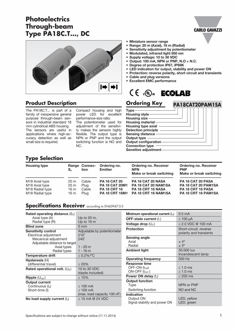
Product DescriptionThe PA18C.T... is part of a family of inexpensive general purpose through-beam sen-sors in industrial standard 18 mm cylindrical ABS housing. The sensors are useful in applications where high-ac-curacy detection as well as small size is required.
Compact housing and high power LED for excellent performance-size ratio.The potentiometer used for adjustment of the sensitivi-ty makes the sensors highly flexible. The output type is NPN or PNP and the output switching function is NO and NC.
• Miniature sensor range• Range: 20 m (Axial), 16 m (Radial)• Sensitivity adjustment by potentiometer• Modulated, infrared light 850 nm• Supply voltage: 10 to 30 VDC• Output: 100 mA, NPN or PNP, N.O + N.C.• Degree of protection IP67, IP69K• LED indication for output, stability and power ON• Protection: reverse polarity, short circuit and transients• Cable and plug versions• Excellent EMC performance
PhotoelectricsThrough-beamType PA18C.T..., DC
Type SelectionHousing type Range Connec- Ordering no. Ordering no. Receiver Ordering no. Receiver Sn tion Emitter NPN PNP Make or break switching Make or break switching M18 Axial type 20 m Cable PA 18 CAT 20 PA 18 CAT 20 NASA PA 18 CAT 20 PASAM18 Axial type 20 m Plug PA 18 CAT 20M1 PA 18 CAT 20 NAM1SA PA 18 CAT 20 PAM1SAM18 Radial type 16 m Cable PA 18 CRT 16 PA 18 CRT 16 NASA PA 18 CRT 16 PASAM18 Radial type 16 m Plug PA 18 CRT 16M1 PA 18 CRT 16 NAM1SA PA 18 CRT 16 PAM1SA
Specifications Receiver according to EN60947-5-2
Rated operating distance (Sn) Axial type (A) Up to 20 m, Radial type (R) Up to 16 mBlind zone 0 mmSensitivity control Adjustable by potentiometer Electrical adjustment 210˚ Mecanical adjustment 240˚ Adjustable distance to target Axial types 1 - 20 m Radial types 1 - 16 m Temperature drift ≤ 0.2%/ºCHysteresis (H) (differential travel) ≤ 20%Rated operational volt. (UB ) 10 to 30 VDC (ripple included)Ripple (Urpp ) ≤ 10% Output current Continuous (Ie) ≤ 100 mA Short-time (I) ≤ 100 mA (max. load capacity 100 nF)No load supply current (Io) ≤ 15 mA @ 24 VDC
Minimum operational current (Im) 0.5 mAOFF-state current (Ir ) ≤ 100 µAVoltage drop (Ud ) ≤ 2.0 VDC @ 100 mAProtection Short-circuit, reverse polarity and transientsSensing angle Axial ± 4º Radial ± 3º Ambient light 30.000 lux Incandescent lampOperating frequency 500 HzResponse time OFF-ON (tON) ≤ 1.0 ms ON-OFF (tOFF ) ≤ 1.0 msPower ON delay (tv) ≤ 200 msOutput function Type NPN or PNP Switching function NO and NCIndication Output ON LED, yellow Signal stability and power ON LED, green
Ordering KeyTypeHousing styleHousing sizeHousing materialHousing type axialDetection principleSensing distanceOutput typeOutput configurationConnection typeSensitive adjustment
PA18CAT20PAM1SA
2 Specifications are subject to change without notice (17.11.2014)
PA18C.T...
Specifications Common according to EN60947-5-2
Environment Installation category III (IEC 60664/60664A; 60947-1) Pollution degree 3 (IEC 60664/60664A; 60947-1) Degree of protection IP 67, IP 69K*Ambient temperature Operating -25° to +60°C (-13° to +140°F) Storage -40° to +70°C (-40° to +158°F)Vibration 10 to 150 Hz, 1 mm/15 G (IEC 60068-2-6)Shock 30 g / 11ms, 3 pos, 3 neg per axis (IEC 60068-2-6, 60068-2-32)Rated insulation voltage 500 VAC (rms) IEC protection class III
Housing material Body ABS, grey Front material PMMA, red Cable gland POM, Black Trimmer shaft POM, Dark Grey Locknuts PBTB, black Mounting bracket PPA, black Connection Cable PVC, grey, 2 m Receiver 4 x 0.25 mm2, Ø = 4.5 mm Emitter 2 x 0.25 mm2, Ø = 4.5 mm Plug M12, 4-pin (CONM14NF-series)Weight With cable: 85 g With plug: 25 gCE-marking YesApprovals cULus (UL508) supply class 2
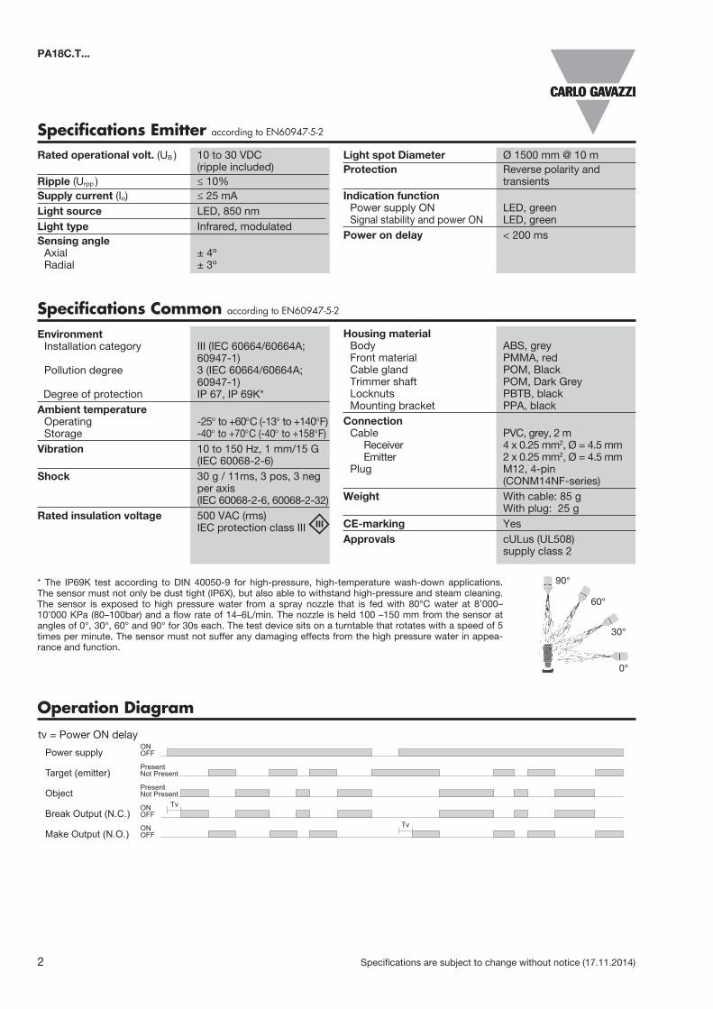
Operation DiagramOperation DiagramPower supply OFF
ON
Target (emitter) Not PresentPresent
Make Output (N.O.) OFFON
Tv
Tv
Break Output (N.C.) OFFON
Object Not PresentPresent
tv = Power ON delay
* The IP69K test according to DIN 40050-9 for high-pressure, high-temperature wash-down applications. The sensor must not only be dust tight (IP6X), but also able to withstand high-pressure and steam cleaning. The sensor is exposed to high pressure water from a spray nozzle that is fed with 80°C water at 8’000– 10’000 KPa (80–100bar) and a flow rate of 14–6L/min. The nozzle is held 100 –150 mm from the sensor at angles of 0°, 30°, 60° and 90° for 30s each. The test device sits on a turntable that rotates with a speed of 5 times per minute. The sensor must not suffer any damaging effects from the high pressure water in appea-rance and function.
90°
60°
30°
0°
Specifications Emitter according to EN60947-5-2
Rated operational volt. (UB ) 10 to 30 VDC (ripple included)Ripple (Urpp ) ≤ 10% Supply current (Io) ≤ 25 mALight source LED, 850 nmLight type Infrared, modulated Sensing angle Axial ± 4º Radial ± 3º
Light spot Diameter Ø 1500 mm @ 10 mProtection Reverse polarity and transients Indication function Power supply ON LED, green Signal stability and power ON LED, greenPower on delay < 200 ms

Specifications are subject to change without notice (17.11.2014) 3
PA18C.T...
Wiring Diagrams
1 BN
4 BK
3 BU
2 WH
V
3 BU
4 BK
2 WH
1 BN VPNPNPN
GNDV GNDV
3 BU
1 BN V
GNDV
Receiver
Emitter
Excess Gain
RadialAxial
0,0 16,4 32,8 49,2 65,6 82,0
1
10
100
1.000
0 5 10 15 20 25
Distance (m)
Exc
ess
Gai
n
(feet)
0,0 16,4 32,8 49,2 65,6
1
10
100
1.000
0 5 10 15 20
Distance (m)
Exc
ess
Gai
n
(feet)
Detection Diagram
RadialAxial
Distance (m)
(mm
)
(feet)
(inch
)
0,0 16,4 32,8 49,2 65,6 82,0
-150
-100
-50
0
50
100
150
0,0 5,0 10,0 15,0 20,0 25,0
-5,9
-3,9
-2,0
0,0
2,0
3,9
5,9
-2,0-1,6-1,2-0,8-0,40,00,40,81,21,62,0
0,0 2,0 4,0 6,0 8,0 10,0 12,0 14,0 16,0 18,0
6,6 13,1 19,7 26,2 32,8 39,4 45,9 52,5 59,1
-50-40-30-20-10
01020304050
0,0
Distance (m)
(mm
)
(feet)
(inch
)
YX
Emitter
Receiver
4 Specifications are subject to change without notice (17.11.2014)
PA18C.T...
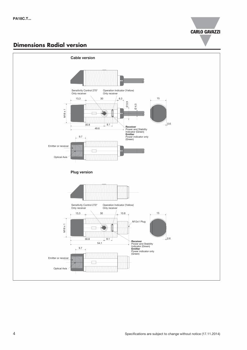
Dimensions Radial version
Plug version
Cable version
Sensitivity Control 270°Only receiver
Operation Indicator (Yellow)Only receiver
ReceiverPower and Stability Indicator (Green)EmitterPower indicator only (Green)
Optical Axis
1530 6.313,3
30.8 8.1
49.6
M18
x 1
Ø 9
.9
Ø 4
.5
0.6
9.7
Sensitivity Control 270°Only receiver
Operation Indicator (Yellow)Only receiver
ReceiverPower and Stability Indicator (Green)EmitterPower indicator only (Green)
Optical Axis
1530 10.813,3
30.8 8.1
54.1
M18
x 1
0.6
9.7
M12x1 Plug
Emitter or receiver
Emitter or receiver
Specifications are subject to change without notice (17.11.2014) 5
PA18C.T...
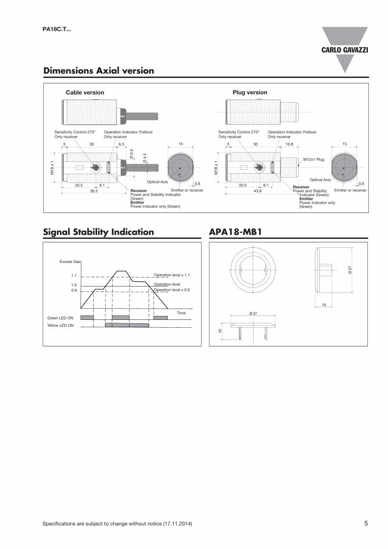
Dimensions Axial version
Plug versionCable version
Sensitivity Control 270°Only receiver
Operation Indicator (Yellow)Only receiver
ReceiverPower and Stability Indicator (Green)EmitterPower indicator only (Green)
Optical Axis
1530 6.33
20.5 8.1
39.3
M18
x 1
Ø 9
.9
Ø 4
.5
0.6
Sensitivity Control 270°Only receiver
Operation Indicator (Yellow)Only receiver
ReceiverPower and Stability Indicator (Green) Emitter Power indicator only (Green)
Optical Axis
Emitter or receiver
1530 10.83
20.5 8.1
43.8
M18
x 1
0.6
M12x1 Plug
Signal Stability Indication
Green LED ONTime
Yellow LED ON
1.0Operation level x 0.9Operation level
Operation level x 1.1
Excess Gain
1.1
0.9
APA18-MB1
10
Ø 2
7
10
Ø 27
Emitter or receiver

6 Specifications are subject to change without notice (17.11.2014)
Delivery Contents• Photoelectric switch: PA 18 C.T...• Installation instruction on plastic bag• Screwdriver• Mounting bracket APA18-MB1• 2 M18 locknuts• Packaging: Plastic bag• Emitter and receiver is packed separately
To avoid interference from inductive voltage /current peaks, separate the proximity switchcables from any other power cables. E.g.Engine, contactor or solenoid cables
Incorrect
Correct
The cable should not be pulledA proximity switch should not serveas mechanical stop
Any repetitive flexing of thecable should be avoided
Relief of the cable strain Protection of the sensing face Sensor mounted on a mobile carrier
Incorrect
> 100 mm
CorrectCorrect
Incorrect
Installation Hints
Accessories• Connector type CONG1A.. / CONM14NF.. series
PA18C.T...
Mounting Systems
Radial versionAxial version
PA18 mounting with a combination of 1 x APA18-MB1 and 1 x M18 locknut. Maximum torque 0.9 NM
PA18 mounting with a combination of 2 x M18 locknuts. Maximum torque 2.0 NM
APA18-MB1 APA18-MB1
M18 Locknut M18 Locknut
Min. 1.0 m
m
Max. 4
.5 mm