
Photocatalysis: semiconductor physics · Photocatalysis: semiconductor physics Carlos J. Tavares...
30
Photocatalysis : semiconductor physics Carlos J. Tavares Center of Physics, University of Minho, Portugal [email protected] www.fisica.uminho.pt
Transcript of Photocatalysis: semiconductor physics · Photocatalysis: semiconductor physics Carlos J. Tavares...
1
Photocatalysis: semiconductor physics
Carlos J. TavaresCenter of Physics, University of Minho, Portugal
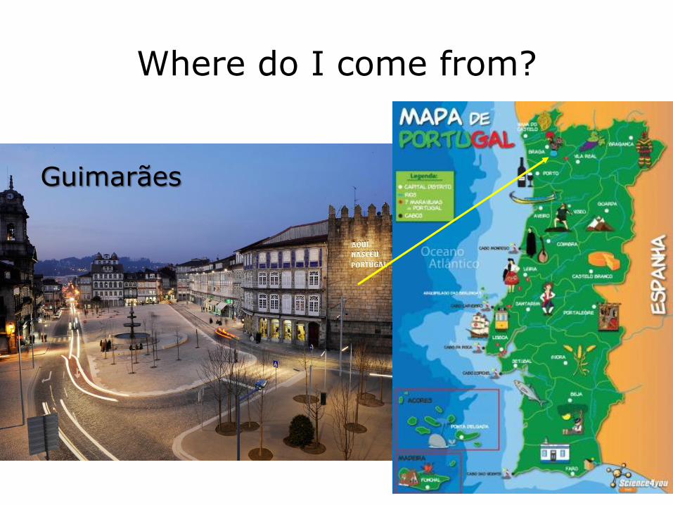
Where do I come from?
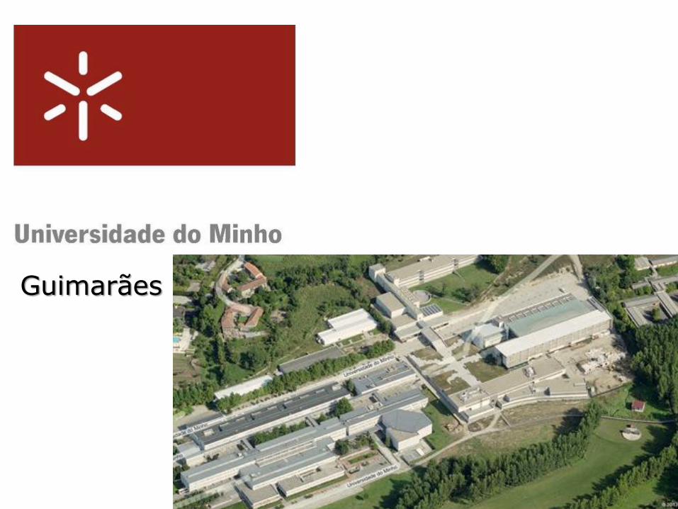
Guimarães

3
4
Guimarães
55
Introduction>>
• Photocatalysis is an active, attractive, andgrowing area regarding the removal of organicpollutants from water and air.
• It is based on the photonic activation of ametal oxide (semiconductor) catalyst.
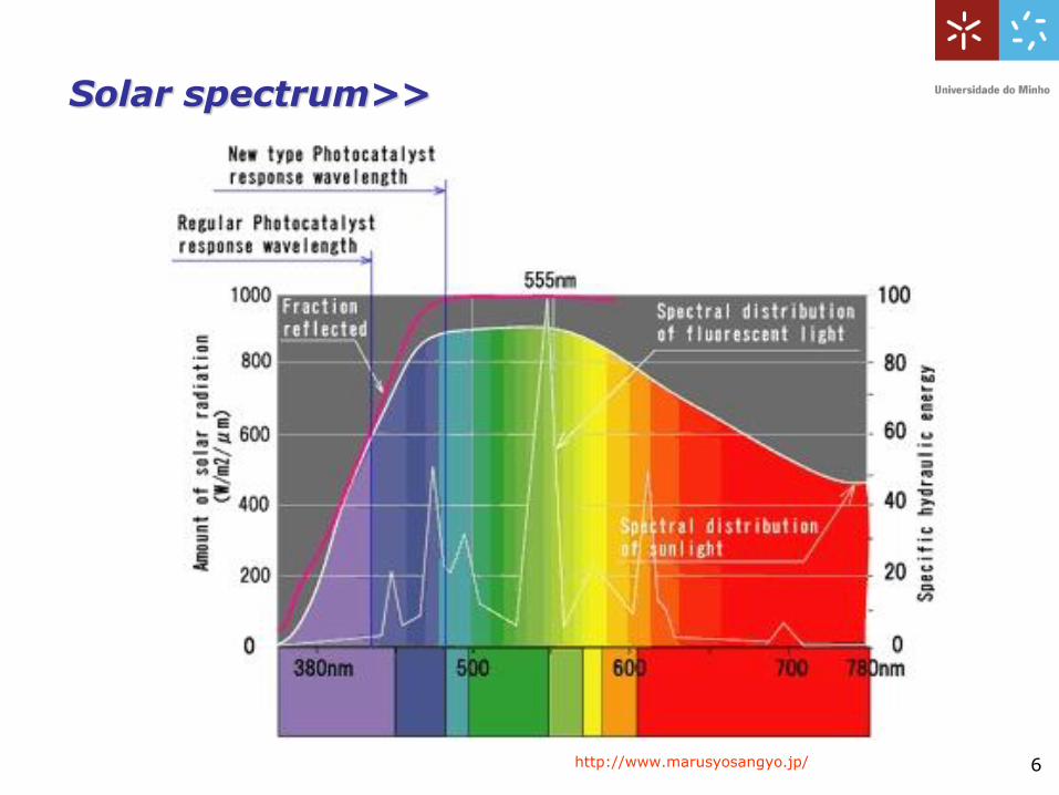
• In order to increase the photocatalyticefficiency of these photocatalysts, it isimportant to enhance their specific surfacearea, crystallinity and the absorption oflight from the solar spectra amongst otherproperties.
6
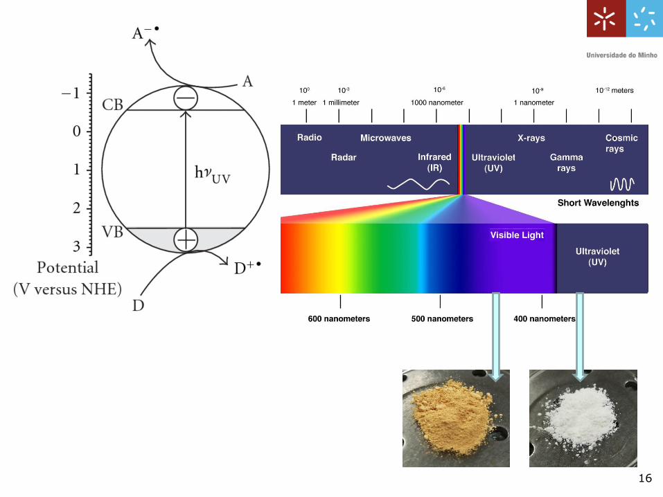
Solar spectrum>>
http://www.marusyosangyo.jp/
7
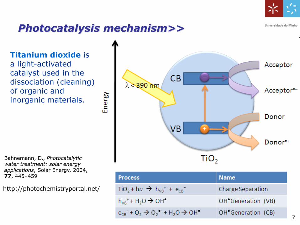
Titanium dioxide is a light-activated catalyst used in the dissociation (cleaning) of organic and inorganic materials.
Photocatalysis mechanism>>
http://photochemistryportal.net/
Bahnemann, D., Photocatalyticwater treatment: solar energyapplications, Solar Energy, 2004, 77, 445–459
7
8
Promotion of an electron to the conduction band, on irradiation by UVlight, results in a ‘hole’ in the valence band – essentially a detriment ofthe electron density that was localized on that orbital, and usuallyassigned a positive charge to symbolize the loss of negative. The holeis powerfully oxidizing – the orbital very much wants to retrieveelectron density just lost after light irradiation. It can retrieve this simplyby the electron in the conduction band recombining with the valenceband – recombination is a sum of radiative (i.e. emission may beobserved) and non-radiative processes. Based on the energy gap law,the fact that rutile energy levels are closer mean that the non-radiativeprocess is more efficient, and hence recombination is more efficient.
Alternative pathways to recombination are possible, and as you canguess, these result in the use of these materials as photocatalysts.The hole has the potential to oxidize water that may be on the surface ofthe material resulting in the formation of hydoxyl radicals. Hydroxylradicals are themselves very powerful oxidisers, and can easilyoxidize any organic species that happens to be nearby, ultimately tocarbon dioxide and water. Meanwhile, upstairs in the conduction band,the electron has no hole to recombine with, since the hole has oxidizedsurface bound water. It quickly looks for an alternative to reduce, andrapidly reduces oxygen to form the superoxide anion. This cansubsequently react with water to form, again, the hydroxyl radical.
9
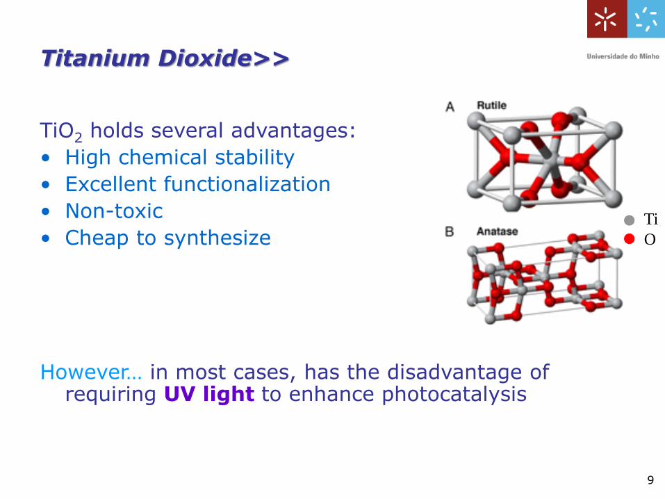
Titanium Dioxide>>
TiO2 holds several advantages:
• High chemical stability
• Excellent functionalization
• Non-toxic
• Cheap to synthesize
However… in most cases, has the disadvantage of requiring UV light to enhance photocatalysis
Ti
O
10
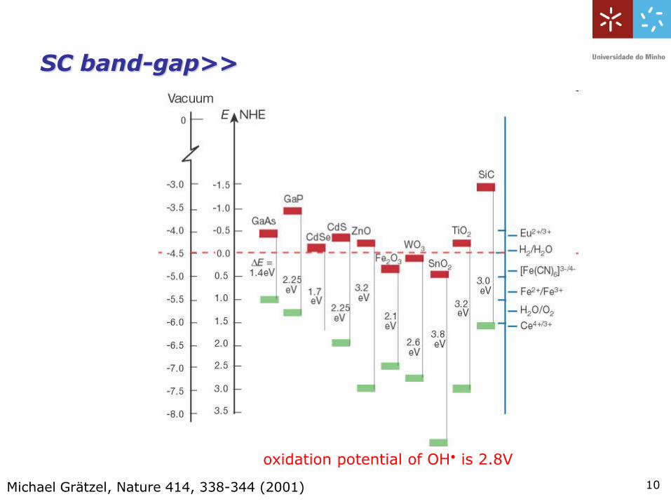
oxidation potential of OH• is 2.8V
SC band-gap>>
Michael Grätzel, Nature 414, 338-344 (2001)
11
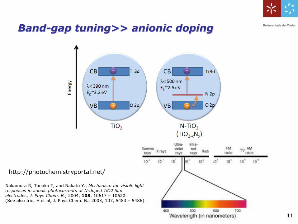
http://photochemistryportal.net/
Band-gap tuning>> anionic doping
Nakamura R, Tanaka T, and Nakato Y., Mechanism for visible light responses in anodic photocurrents at N-doped TiO2 filmelectrodes, J. Phys Chem. B., 2004, 108, 10617 – 10620. (See also Irie, H et al, J. Phys Chem. B., 2003, 107, 5483 – 5486).
12
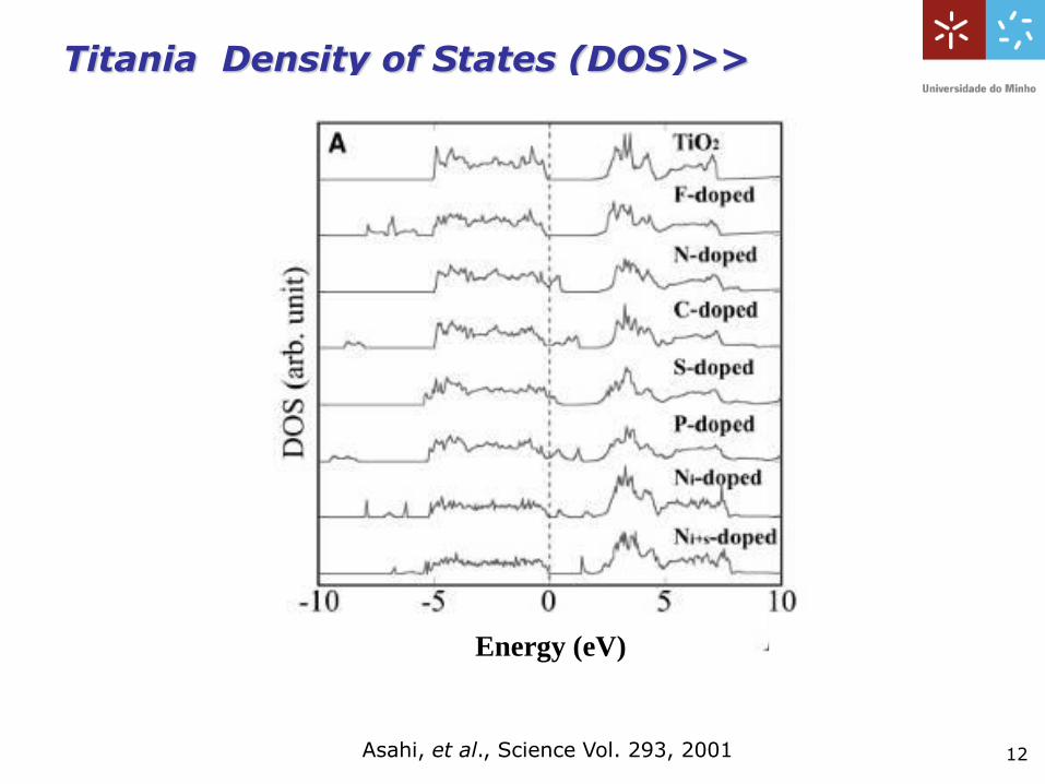
Titania Density of States (DOS)>>
Asahi, et al., Science Vol. 293, 2001
Energy (eV)
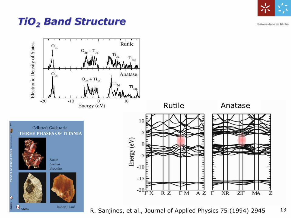
TiO2 Band Structure
13
Rutile Anatase
R. Sanjines, et al., Journal of Applied Physics 75 (1994) 2945
14
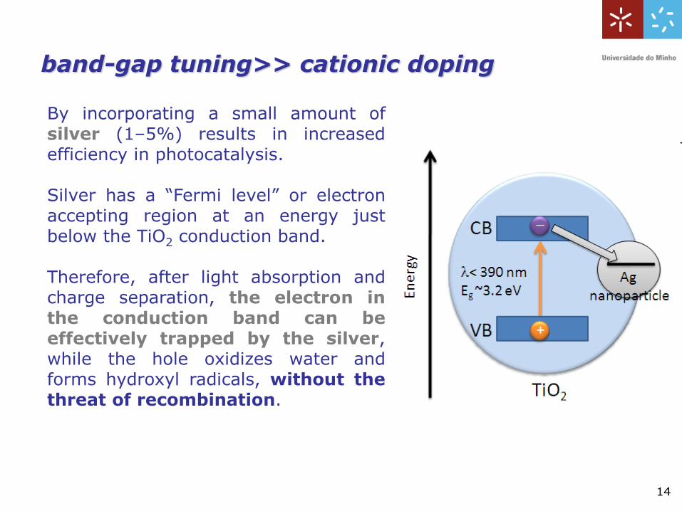
By incorporating a small amount ofsilver (1–5%) results in increasedefficiency in photocatalysis.
Silver has a “Fermi level” or electronaccepting region at an energy justbelow the TiO2 conduction band.
Therefore, after light absorption andcharge separation, the electron inthe conduction band can beeffectively trapped by the silver,while the hole oxidizes water andforms hydroxyl radicals, without thethreat of recombination.
band-gap tuning>> cationic doping
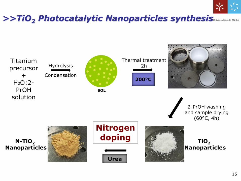
>>TiO2 Photocatalytic Nanoparticles synthesis
Titanium precursor
+H2O:2-PrOH
solution
SOL
200°C
2-PrOH washing and sample drying
(60°C, 4h)
TiO2
NanoparticlesN-TiO2
Nanoparticles
Urea
Hydrolysis
Condensation
Thermal treatment2h
Nitrogen doping
15
16
3,0 3,5 4,0 4,50
1
2
3
4
5
6
7
8
[F(R
)h]0
.5 (
arb
. un
its)
h (eV)
TiO2
TiO2 tangent
N-TiO2 (1g)
N-TiO2 (1g) tangent
N-TiO2 (4g)
N-TiO2 (4g) tangent
3,0 3,5 4,0 4,50
1
2
3
4
5
6
7
8
[F(R
)h]0
.5 (
arb
. un
its)
h (eV)
TiO2
TiO2 tangent
TiO2 100ºC
TiO2 100ºC tangent
TiO2 200ºC
TiO2 200ºC tangent
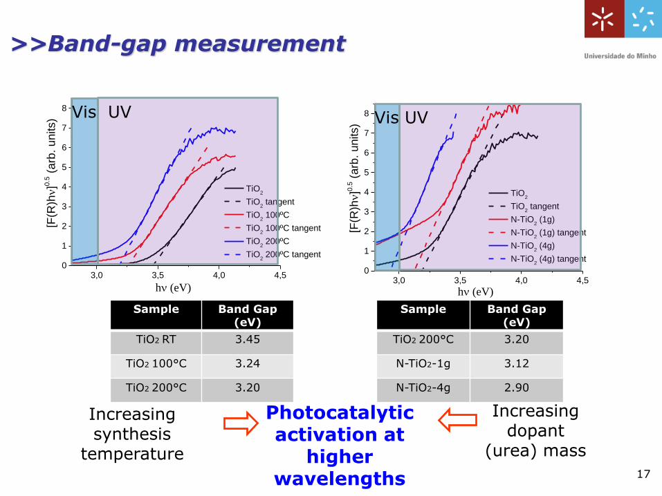
Sample Band Gap (eV)
TiO2 RT 3.45
TiO2 100°C 3.24
TiO2 200°C 3.20
Sample Band Gap (eV)
TiO2 200°C 3.20
N-TiO2-1g 3.12
N-TiO2-4g 2.90
17
Photocatalytic activation at
higher wavelengths
Increasing synthesis
temperature
Increasing dopant
(urea) mass
Vis UVVis UV
>>Band-gap measurement
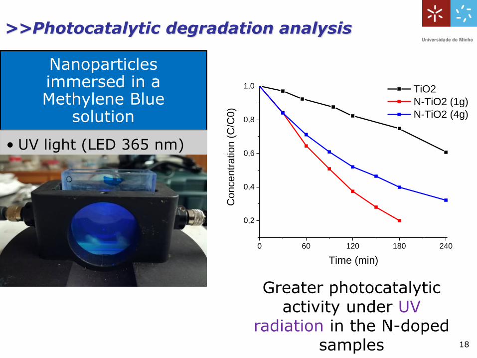
>>Photocatalytic degradation analysis
Greater photocatalytic activity under UV
radiation in the N-doped samples
0 60 120 180 240
0,2
0,4
0,6
0,8
1,0
Co
nce
ntr
atio
n (
C/C
0)
Time (min)
TiO2
N-TiO2 (1g)
N-TiO2 (4g)
Nanoparticles immersed in a Methylene Blue
solution
• UV light (LED 365 nm)
18
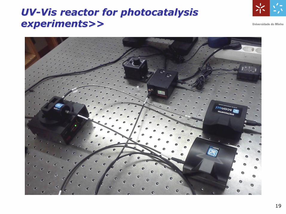
19
UV-Vis reactor for photocatalysis experiments>>
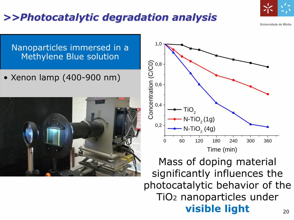
0 60 120 180 240 300 360
0,2
0,4
0,6
0,8
1,0
Co
nce
ntr
atio
n (
C/C
0)
Time (min)
TiO2
N-TiO2 (1g)
N-TiO2 (4g)
Mass of doping material significantly influences the
photocatalytic behavior of the TiO2 nanoparticles under
visible light
Nanoparticles immersed in a Methylene Blue solution
• Xenon lamp (400-900 nm)
20
>>Photocatalytic degradation analysis
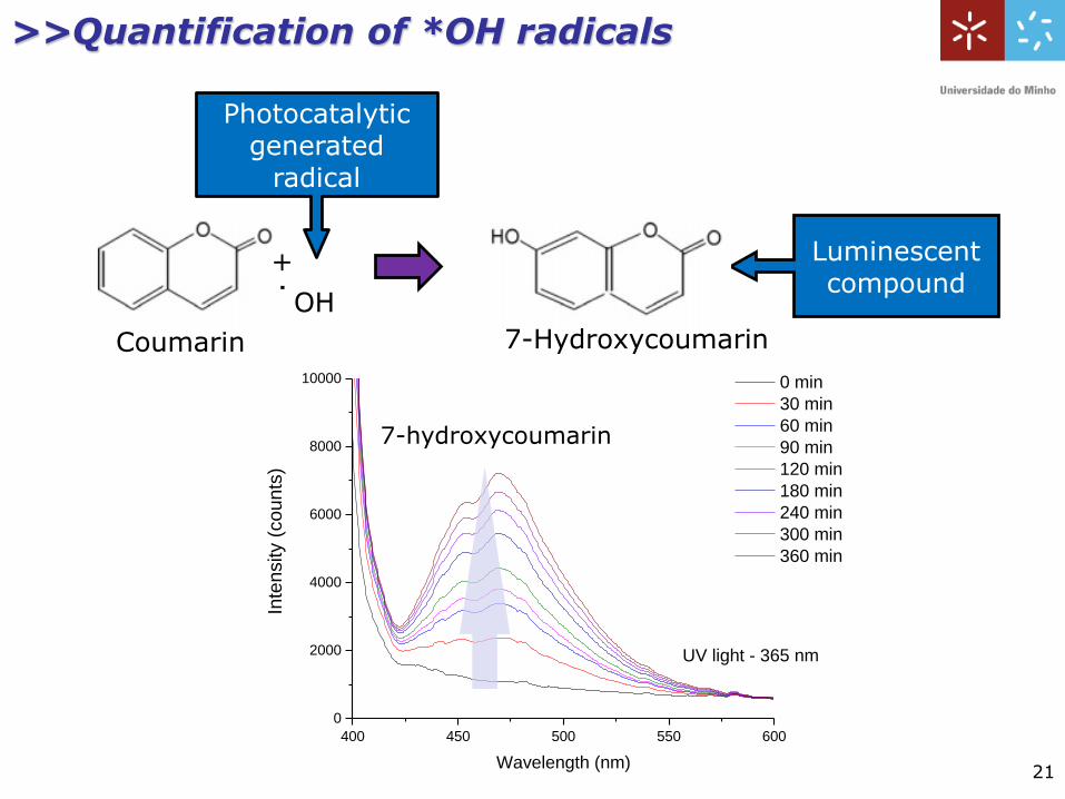
400 450 500 550 600
0
2000
4000
6000
8000
10000
Inte
nsity (
counts
)
Wavelength (nm)
0 min
30 min
60 min
90 min
120 min
180 min
240 min
300 min
360 min
UV light - 365 nm
Photocatalytic generated
radical
Luminescent compound
Coumarin
+
˙OH
7-Hydroxycoumarin
7-hydroxycoumarin
21
>>Quantification of *OH radicals
22
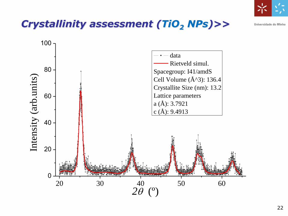
Crystallinity assessment (TiO2 NPs)>>
20 30 40 50 600
20
40
60
80
100
data
Rietveld simul.
Spacegroup: I41/amdS
Cell Volume (Å^3): 136.4
Crystallite Size (nm): 13.2
Lattice parameters
a (Å): 3.7921
c (Å): 9.4913
Inte
nsi
ty (
arb
.un
its)
2 (º)
23
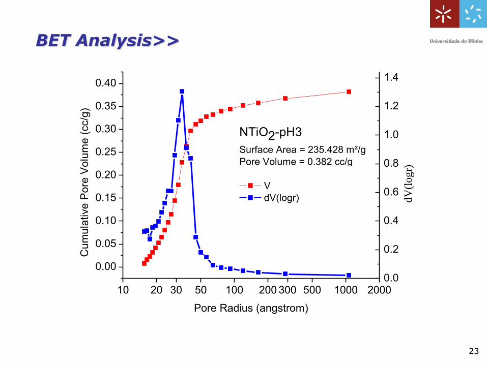
BET Analysis>>
10 20 30 50 100 200 300 500 1000 2000
0.00
0.05
0.10
0.15
0.20
0.25
0.30
0.35
0.40C
um
ula
tive P
ore
Volu
me (
cc/g
)
Pore Radius (angstrom)
NTiO2-pH3
Surface Area = 235.428 m²/g
Pore Volume = 0.382 cc/g
Pore Radius Dv(r) = 33.955 إ
V
dV(logr)
0.0
0.2
0.4
0.6
0.8
1.0
1.2
1.4
dV
(lo
gr)
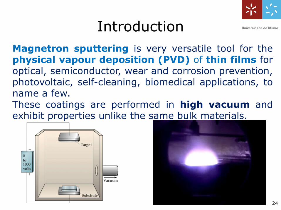
Magnetron sputtering is very versatile tool for thephysical vapour deposition (PVD) of thin films foroptical, semiconductor, wear and corrosion prevention,photovoltaic, self-cleaning, biomedical applications, toname a few.These coatings are performed in high vacuum andexhibit properties unlike the same bulk materials.
24
Introduction
252525
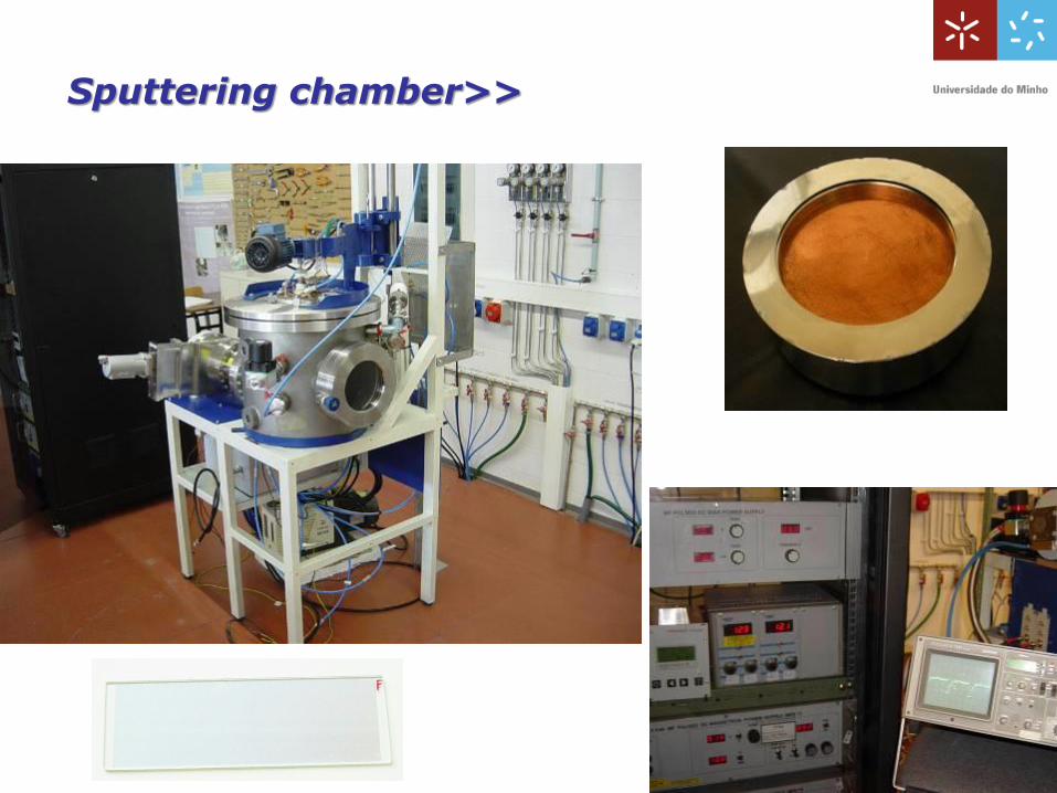
Sputtering chamber>>
26
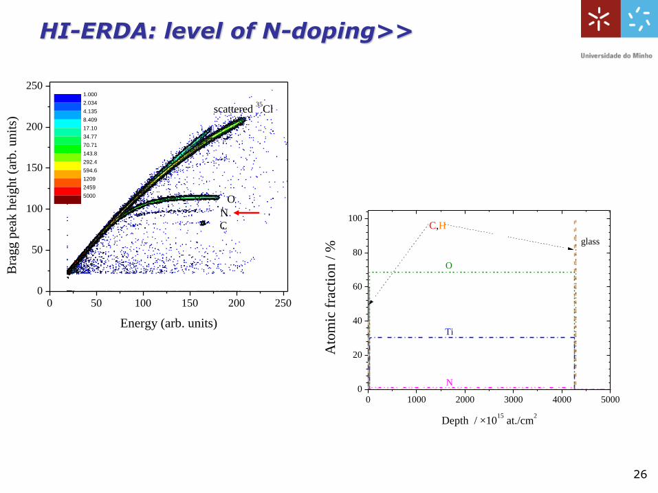
HI-ERDA: level of N-doping>>
0 1000 2000 3000 4000 50000
20
40
60
80
100
Ato
mic
fra
ctio
n /
%
Depth / ×1015
at./cm2
glass
Ti
O
C,H
N
0 50 100 150 200 2500
50
100
150
200
250
Energy (arb. units)
Bra
gg p
eak h
eight
(arb
. unit
s)
1.000
2.034
4.135
8.409
17.10
34.77
70.71
143.8
292.4
594.6
1209
2459
5000
C
N
O
scattered 35
Cl
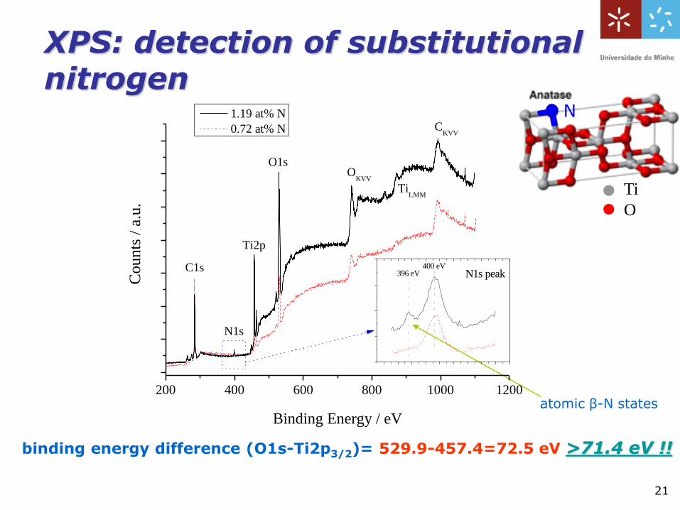
XPS: detection of substitutionalnitrogen
200 400 600 800 1000 1200
N1s
CKVV
TiLMM
OKVV
O1s
Ti2p
N1s peak400 eV
396 eV
Counts
/ a
.u.
Binding Energy / eV
1.19 at% N
0.72 at% N
C1s
binding energy difference (O1s-Ti2p3/2)= 529.9-457.4=72.5 eV >71.4 eV !!
atomic β-N states
21
Ti
O
N
28
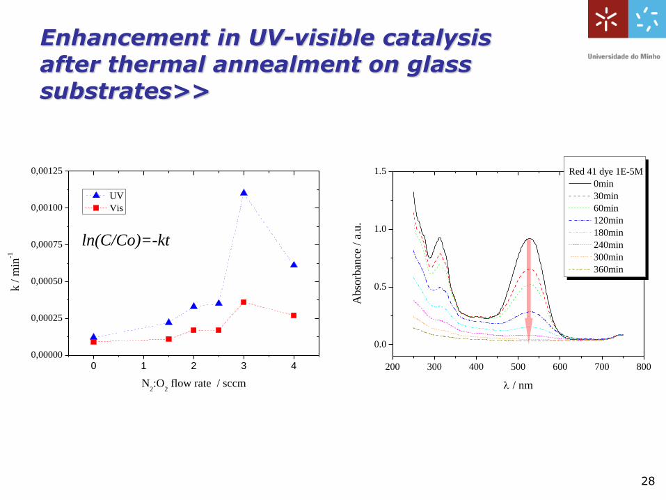
Enhancement in UV-visible catalysisafter thermal annealment on glass substrates>>
200 300 400 500 600 700 800
0.0
0.5
1.0
1.5
Ab
sorb
ance
/ a
.u.
/ nm
Red 41 dye 1E-5M
0min
30min
60min
120min
180min
240min
300min
360min
0 1 2 3 40,00000
0,00025
0,00050
0,00075
0,00100
0,00125
UV
Vis
k /
min
-1
N2:O
2 flow rate / sccm
ln(C/Co)=-kt
Thank you for your attention