Photo by: Steffen Heilfort (1.07.2006)
64
Photo by: Steffen Heilfort (1.07.2006) Training Course on Geothermal Electricity 15 18 April 2013, Potsdam, Germany Manual
Transcript of Photo by: Steffen Heilfort (1.07.2006)

Photo by: Steffen Heilfort (1.07.2006)
Training Course on Geothermal Electricity
15 18 April 2013, Potsdam, Germany
Manual

2

This document has been edited by:
F. Schütz and A. Spalek,
Helmholtz Centre Potsdam GFZ German Research Centre for Geosciences,
Telegrafenberg, 14473 Potsdam, Germany
D. Mendrinos and C. Karytsas,
Centre for Renewable Energy Sources and Saving,
19th km Marathonos ave., 19009 Pikermi Attikis, Greece
for the Second Training Course on Geothermal Electricity, 1518 April 2013, in Potsdam,
Germany, organized in the framework of the GEOELEC project.
The GEOELEC project is a pan‐European project on geothermal electricity, supported by the
Intelligent Energy Europe programme of the EU. The objective of the GEOELEC project is to
convince decision‐makers about the potential of geothermal electricity in Europe, to
stimulate banks and investors in financing geothermal power installations and finally, to
attract key potential investors such as oil and gas companies, and electrical utilities to invest
in geothermal power. One key element will be to present them the huge geothermal
potential in Europe (http://www.geoelec.eu/).
GEOELEC Partners
European Geothermal Energy Council (EGEC)
Bureau De Recherches Géologiques et Minières (BRGM), France
Centre for Renewable Energy Sources and Saving (CRES), Greece
Consiglio Nazionale delle Ricerche, Istituto Di Geoscienze e Georisorse (CNR‐IGG), Italy
Asociacion De Productores De Energias Renovables (APPA), Spain
Gaßner, Groth, Siederer & Coll. (GGSC), Germany
Energie Baden‐Württemberg AG (EnBW), Germany
Mannvit, Iceland
Helmholtz Centre Potsdam German Research Centre for Geosciences (GFZ), Germany
Nederlandse Organisatie Voor Toegepast Natuurwetenschappelijk Onderzoek (TNO),
Netherlands
3

4
In references, each contribution of this document will be referenced as the following
example:
Manzella, A., Durst, P., van Wees, J.‐D., and Dezayes, C., 2012. Geothermal exploration and
resource assessment. Schütz, F., Spalek, A., Mendrinos, D., and Karytsas, C. (eds.), in Manual
of the Training Course on Geothermal Electricity, 1518 April 2013, Potsdam, Germany, pp.
1825.
Keywords: Geothermal electricity, market aspects, legal/environmental and financial
aspects, Enhanced Geothermal Systems (EGS), geothermal exploitation/exploration,
resource assessment, EGS technology, geothermal well drilling, reservoir exploitation
assessment, flash steam and binary technology, plant operation, energy supply and grid
integration

Contents
Session I – Market aspects C. Karytsas and D. Mendrinos ................................................................................................ 6
Session II – Legal, environmental and financial aspects S. Fraser, F. Jaudin and T. Reif .............................................................................................. 14
Session III – Geothermal exploration and resource assessment A. Manzella, J.‐D. van Wees, P. Durst and C. Dezayes ......................................................... 18
Session IV – EGS technology J.‐D. van Wees, G. Zimmermann, P. Durst and C. Dezayes.................................................. 26
Session V – Drilling W. Brandt ............................................................................................................................. 34
Session VI – Flash steam and binary technology E. Hallgrímsdóttir and P. Bombarda..................................................................................... 42
Session VII – Plant operation, energy supply and grid integration F. Heilemann and S. Reith .................................................................................................... 54
The sole responsibility for the content of this publication etc. lies with the authors. It does not necessarily reflect the opinion of the European Union. Neither the EACI nor the European Commission are responsible for any use that may be made of the information contained therein.
5

Session I – Market aspects C. Karytsas and D. Mendrinos
Presenters
Constantine Karytsas
Dr., Deputy Dir. of RES Division
[email protected] Dimitrios Mendrinos MEng, MBA, Senior Geothermal Eng. [email protected]
Centre for Renewable Energy Sources and
Saving, (CRES), Greece
Curriculum vitae Dr. Constantine Karytsas has a PhD degree in Geology‐Energy from Pennsylvania State University
(PSU) USA ‐1992, and a MSc degree in Environmental Geochemistry from the University of Newcastle
Upon Tyne (UK) (1984) with over 20 years professional experience in geothermal applications. Recent
work amongst others includes the fields of Seawater Desalination, ORC Binary Cycle Power
Production, Geothermal Direct Heat Applications, Geothermal Heat Pump Research and
Demonstration, and innovative COMBI system Solar Energy Applications. Participation in 80 research
and application/demonstration projects (coordinator in 20 of them) funded by the EU, the European
Industry, the Greek State and the Government of the United States (Departments of Energy and
Environment). Dr. C. Karytsas is the author or co‐author of more than 18 peer reviewed journal
articles and 60 announcements in the proceedings of international conferences.
Served as: Deputy Director of RES division, CRES (2010 – today); Head of the Geothermal Department
of CRES (1989‐2010); Lecturer on Geothermal Applications at Technical University of Crete (since
1994) and National Technical University of Athens – NTUA (2004).
Dimitrios Mendrinos is a geothermal engineer with masters degree in geothermal energy from the
University of Auckland, New Zealand, MBA from the University of Surrey, UK, and more than 20 years
professional experience in geothermal energy matters. His recent work includes R&D and market
development projects on geothermal heat and power (planning, design and management of
geothermal field exploration, exploitation, production monitoring, reservoir engineering and power
generation) and ground source heat pumps. He has been the coordinator of the GROUND‐REACH and
GROUND‐MED European projects, and Technical Manager of the GROUNDHIT and LOW‐BIN
European projects. In addition, he has more than 15 publications in international journals plus 35
announcements in international conferences related to geothermal energy.
Served at: Geothermal Energy Department at CRES (2003‐today), North Greece Office of CRES (2000‐
2003). Omega European Consulting Ltd, Kapa Systems, Geothermiki Ellados and others (1993 –
2000). LDK Consultants, Engineers & Planners (1990 – 1992). Lecturer at the Technical Educational
Institute (TEI) of Piraeus – Fluid Mechanics Laboratory (1990‐2000).
The sole responsibility for the content of this publication etc. lies with the authors. It does not necessarily reflect the opinion of the European Union. Neither the EACI nor the European Commission are responsible for any use that may be made of the information contained therein.
6

Abstract Geothermal resources of Europe can contribute to the EU targets of 20% less greenhouse gas
emissions, 20% RES share and 20% more energy efficiency by 2020. The session provides an
overview of the present status and future prospects of global geothermal electricity market
niche, including market size (turnover, capacities, energy yields), near term growth, quality of
resources, technologies employed, key players, investment and electricity generation costs,
market barriers and incentives.
Keywords: geothermal, power plants, resources, market, development, costs
International Geothermal Market overview Geothermal energy is the heat of the earth. Depending on the geological environment they
are encountered in, geothermal resources are characterized as magmatic/volcanic systems,
thermal aquifers, geopressured basins and crustal heat. A global geothermal resource
estimate of above categories, in comparison to fossil fuel reserves, is presented in Table 1.
Table 1. World geothermal resources compared to global fossil fuel reserves
Geothermal resources billion TOE Fossil fuel reserves (end 2011) billion TOE
Crustal heat 10.775.600 Coal 422
Magmatic/Volcanic 327.360 Oil 234
Geopressured 55.924 Natural gas 188
Aquifers, thermal 18
Geothermal exploitation technology requires drilling one or more production wells
delivering subsurface hot fluids to the surface, which after feeding a geothermal power
plant, are injected back to their origin formations through reinjection wells. In that case, e.g.
when deep hot fluids are available, the geothermal resource is termed as a hydrothermal
system. Almost all geothermal power plants today are located in such hydrothermal
systems, which are encountered mainly at the boundaries of tectonic plates and at
geological hot spots, where hot magma is rising towards a thin earth crust. Location of
geothermal power plants is shown in Figure 1.
The geothermal plant at Soultz, proved that the exploitation of other parts of the earth
crust, where deep hot formations do not naturally deliver the necessary amounts of fluids, is
also technically feasible. In these geologic conditions, the hot rocks are artificially fractured
by hydraulic fracturing, acidizing, propellants, etc., in order to engineer a man made
reservoir, through which surface water is circulated serving as the heat transfer media.
These are termed as enhanced geothermal systems (EGS). At present only a few EGS plants
are in operation or under development around the globe, but future large scale exploitation
of geothermal energy lies in this technology.
The sole responsibility for the content of this publication etc. lies with the authors. It does not necessarily reflect the opinion of the European Union. Neither the EACI nor the European Commission are responsible for any use that may be made of the information contained therein.
7

Figure 1. Power plants around the globe (yellow); the larger the cycle, the higher the installed
plant capacity.
Depending on the temperature and permeability of the geothermal resource, production
wells can deliver to the surface, either dry steam, or two phase mixture of steam and liquid
water, or only liquid water.
Only a handful of dry steam resources are encountered around the globe. The most
important are the geothermal fields of Larderello, Italy, Geysers, California, and Kamojang,
Indonesia. In such fields, the steam from the production wells is directly conveyed to a
steam turbine in order to generate electricity. This is termed as a dry steam plant.
In most cases, production wells deliver a mixture of steam and liquid water, which is flashed
in order to separate the steam and the liquid (flash plant); the steam is conveyed to a
turbine to generate electricity and the separated liquid can be further utilized for power
generation or for its heat (cogeneration plant) and then reinjected to its origin reservoir. A
flash plant is economically feasible if the production wells deliver more than 150°C.
In cases where resource temperature is lower than 150°C, production wells deliver liquid
water with the aid of a submersible or line shaft pump, which feeds a binary power plant. In
such a plant, the hot water delivers its heat to a closed loop of secondary fluid, which
vaporizes, drives a turbine and condenses in a closed cycle (organic Rankine or Kalina).
In general, exploitation of hydrothermal resources down to 3‐4 km depth is a mature
commercial technology done by:
Binary plants for T=100‐180°C
Flash plants for T>180°C
Dry steam at favourable locations
EGS from 3‐6 km depth is a new technology, while supercritical plants (T>350°C) from 5‐10 km depth will be a future technology. The geothermal power market in terms of historical evolution, present status and future projection of installed plants is summarized in Table 2 (world) and Table 3 (EU). Prediction of future installations was based on projects which are at present under development (2015) or
The sole responsibility for the content of this publication etc. lies with the authors. It does not necessarily reflect the opinion of the European Union. Neither the EACI nor the European Commission are responsible for any use that may be made of the information contained therein.
8

announced (2020). The market is dominated by mostly dedicated geothermal field operators and lesser by diversified power utilities, with presence of oil and gas companies, mainly in Indonesia. The six major geothermal field owners and plant operators control >6,5 GWe or 60% of installed capacity. At global level, market growth which was 3% during the past 20 years, is expected to exceed 10% in the next years, resulting in more than double installed geothermal capacity from 11,5 GW today to 24 GW by 2020. At EU level, market growth patterns are expected to increase from 2% today to 6% during the next years, due to wider geothermal development, as EU member states try to reach their 2020 targets for 20% less greenhouse gas emissions, 20% renewable energy share and 20% more energy efficiency, resulting in installed capacity to increase from less than 1 GW today to 1,5 GW in 2020. Table 2. World geothermal power plant capacity
MWe historical evolution present forecast Country 1990 1995 2000 2005 2010 2012 2015 2020USA 2.775 2.817 2.228 2.544 3.093 3.187 4.136 5.442Philippines 891 1.227 1.909 1.931 1.904 1.972 2.112 3.447Indonesia 145 310 590 797 1.197 1.335 2.325 3.453Mexico 700 753 755 953 958 990 1.208 1.208EU 552 641 805 822 896 941 1.113 1.499New Zealand 283 286 437 435 628 750 1.350 1.599Iceland 45 50 170 322 575 675 890 1.285Japan 215 414 547 535 536 537 568 1.807Kenya 45 45 45 127 167 205 402 560El Salvador 95 105 161 151 204 204 287 290Costa Rica 0 55 143 163 166 201 201 201Nicaragua 35 70 70 77 88 124 209 240Turkey 21 20 20 20 82 115 206 1.232Russia 11 11 23 79 82 82 190 194Papua NG 0 0 0 39 56 56 75 75Guatemala 0 33 33 33 52 52 120 141China 19 29 29 28 24 24 60 84Ethiopia 0 0 9 7 7 7 45 70Australia 0 0 0 0 1 1 43 70Chilli 0 0 0 0 0 0 40 160Honduras 0 0 0 0 0 0 35 35Nevis 0 0 0 0 0 0 35 35Argentina 1 1 0 0 0 0 30 300Canada 0 0 0 0 0 0 20 493Thailand 0 0 0 0 0 0 1 1Bolivia 0 0 0 0 0 0 0 100Iran 0 0 0 0 0 0 0 50Peru 0 0 0 0 0 0 0 40Armenia 0 0 0 0 0 0 0 25Tanzania 0 0 0 0 0 0 0 20Norway 0 0 0 0 0 0 0 5Switzerland 0 0 0 0 0 0 0 3 5.832 6.867 7.974 9.064 10.717 11.456 15.701 24.162
The sole responsibility for the content of this publication etc. lies with the authors. It does not necessarily reflect the opinion of the European Union. Neither the EACI nor the European Commission are responsible for any use that may be made of the information contained therein.
9

Table 3. Geothermal power plant capacity in EU member states
MWe historical evolution present forecast Country 1990 1995 2000 2005 2010 2012 2015 2020 Italy 545 632 785 790 843 883 923 1.019
Portugal 3 5 16 16 29 29 39 60
France 4 4 4 15 16 16 41 42
Germany 0 0 0 0 7 12 92 184
other 0 0 0 1 1 1 18 194
552 641 805 822 896 941 1.113 1.499
The different types of installed geothermal power plants today are presented in Table 4,
while the corresponding manufacturers and their market position in Table 5. Average plant
sizes are 5 MWe binary, 30 MWe flash and 45 MWe dry steam, with maximum at around
100‐130 MWe. Six major turbine manufacturers account for 95% of total installed capacity.
Table 4. Types of geothermal power plants installed today
Geothermal plant type installed MWe
Flash, condensing 6.904,3
Dry steam 2.862,0
Binary 1.303,0
Flash, back Pressure 146,6
Table 5. Geothermal power plant manufacturers with their corresponding installed capacity
Manufacturer Steam MWe Binary MWe total MWe Mitsubishi 2.729 2.882 Toshiba 2.721 25 2.746 Fuji 2.315 2.423 Ormat 1.234 1.234 Ansaldo 1.556 1.556 General Electric 532 532 Alstom 155 155 Assoc. Elec. Ind. 90 90 Kaluga 72 10 82 British Thomson Houston 82 82 Mafi Trench 72 72 Qingdao Jieneng 62 62 UTC Turboden (MHI) 19 19 Kawasaki 15 15 Westinghouse 14 14 Elliot 12 12 Harbin 11 11 Enex 11 11 Turbine air system 8 8 Parsons 5 5 Makrotek 5 5 Siemens 4 4 misc. 3 3
The sole responsibility for the content of this publication etc. lies with the authors. It does not necessarily reflect the opinion of the European Union. Neither the EACI nor the European Commission are responsible for any use that may be made of the information contained therein.
10

The investment costs of geothermal power plants depend on the depth, temperature and
chemistry of the resource, as well as the delivery flow rates of the wells. The dry steam, flash
and binary plants in operation today exploit the most favourable resources usually from 2‐3
km depth, going down to 4‐5 km for EGS plants. Investment and levelized electricity
generation costs in recent projects are shown in Table 6. Investment costs include
exploration, field development and power plant.
In order to estimate the electricity generation costs presented in Table 6, typical operation
costs of 0,011‐0,020 €/kWh were assumed, an investment discount factor of 8% for 20 years,
as well load factors relevant to the installed country: 90% for USA, Portugal and Germany,
80% for Iceland and world average and 70% for Italy, Turkey and EU average.
The main aspects of global and EU geothermal power markets are summarized in Table 7.
Main market barriers hindering geothermal deployment are lengthy permitting procedures,
lack of regulations, high risk in finding & identifying geothermal resources and associated
finance availability, as well as know how and competent personnel to few companies only.
In USA, geothermal development is driven by federal and state incentives available to energy
producers, manufacturers and utilities, which are summarized in Table 8. They include
renewable portfolio standards, tax exemptions, investment subsidies and access to grid.
In EU, geothermal development is supported by feed in tariffs, with the tendency to be
replaced by feed in premiums. Following the successful example of Germany, Japan,
Indonesia and Turkey have recently introduced aggressive feed in tariff schemes, in order to
stimulate large scale geothermal power development in their territory. A list of available
feed in tariffs is presented in Table 9.
Table 6. Economic aspects of geothermal power generation
recent projects Investment, €/MWe Energy production costs, €/kWh
Flash Binary EGS Flash Binary EGS
USA 2.700.000 3.100.000 6.200.000 0,055 0,060 0,100
Indonesia, New Zealand, Philippines
2.300.000 0,044
EU ‐ Germany
4.500.0006.500.000
11.600.000
0,095 0,104
0,213
Chile 3.600.000 0,072
Turkey 2.750.000 0,066
Table 7. Global and EU market size and growth
2012 2012‐2020
installed annual sales annual growth capacity electricity value capacity investments MWe GWh billion € MWe billion €
World 11.456 71.887 7,2 1.588 4,4
EU 941 5.982 0,9 70 0,5
The sole responsibility for the content of this publication etc. lies with the authors. It does not necessarily reflect the opinion of the European Union. Neither the EACI nor the European Commission are responsible for any use that may be made of the information contained therein.
11

Table 8. Incentives to geothermal electricity development in USA Jurisdiction Statute Incentive Title Tax Type Taxpayer yrs Amount Max Expire
Federal §45 Renewable Electricity Production Income Credit Producer 10 $0.022/Kwh ‐ 2013
§48 Investment In Energy Property Income Credit Owner 5 10% ‐ 2016
§168(e)(3) Certain Energy Property Income Deduction Owner 5 200% DB ‐ 2016
Alabama §40‐18‐190 Alternat. Energy Electricity Prod. Facilities Income Credit Utility 20 5% ‐ 2015
§40‐9B‐4 Alternative Energy Production Facilities Property Abatement Utility ‐ 100% ‐ 2018
Florida §196.175 Renewable Energy Source Devices Property Exemption Owner 10 100% ‐ ‐
§220.193 Renewable Energy Production Income Credit Producer ‐ $0.01/kWh $1 million 2016
Illinois 35 §10/5 Ren. Energy & Conservation Job Creation Income Credit Employer 10/15 Varies ‐ ‐
Indiana §6‐1.1‐12‐26 Renewable Energy Property Property Exemption Owner ‐ 100% ‐ ‐
Kentucky §154.27‐010 Renewable Energy Facilities Income Credit Producer ‐ 50% ‐ ‐
§154.27‐010 Renewable Energy Facilities Sales Exemption Purchaser 25 100% ‐ ‐
Maryland §10‐720 Renewable Energy Production Income Credit Producer 5 $0.0085/kWh $2.5 million 2015
§9‐203 Solar, Geothermal & Conservation Devel. Property Credit Owner ‐ 100% ‐ ‐
§7‐242 Renewable Energy Systems Property Exemption Owner ‐ 100% ‐ ‐
Massachusetts 62§ 2a(2)(G) Conservation / Alternative Energy Patents Income Deduction Owner 5 100% ‐ ‐
Michigan §125.2681 Renewable Energy Renaissance Zones Varies Abatement Owner 15 100% ‐ ‐
Mississippi §27‐7‐22.29 Alternative Energy Job Creation Income Credit Employer 20 $1,000/emp 100% liab
HB1701 2010 Clean Energy Manufacturing Facilities Income Exemption Manufacturer 10 100% ‐ ‐
HB1701 2010 Clean Energy Manufacturing Facilities Franchise Exemption Manufacturer 10 100% ‐ ‐
HB1701 2010 Clean Energy Manufacturing Facilities Sales Exemption Manufacturer 10 100% ‐ ‐
New Hampshire 72 §73 Renewable Generation Facilities Property Abatement Owner 5 Varies ‐ ‐
New Jersey §54:10A Alternative Energy Technology Company Income Credit Investor 3 30% $500,000 ‐
§54:4‐3.113 Renewable Energy Systems Property Exemption Owner ‐ 100% ‐ ‐
North Carolina §105‐130.28 Renewable En. Property Manufacturing Fac. Income Credit Manufacturer 5 25% ‐ 2013
Ohio §3706 Air Quality Renewable/Energy Efficiency/Con Property Exemption Owner ‐ ‐ 100% ‐ ‐
Pennsylvania 73 §1649.701 Alternative Energy Production Income Credit Producer ‐ 15% $1 million 2016
Rhode island §44‐18‐30(57 Renewable Energy Systems & Equipment Sales Exemption Purchaser ‐ 100% ‐ ‐
§44‐3‐21 Renewable‐Energy Systems Property Exemption Owner ‐ 100% ‐ ‐
South Carolina §12‐6‐3588 Renewable En. Manufacturing Plant/Equip Income Credit Owner 15 10% $5 million 2015
Tennessee §67‐6‐232 Manufacturers Of Clean Energy Tech. Sales Credit Manufacturer 8 99.50% ‐ ‐
§67‐4‐2109(n Green Energy Supply Chain Manufacturers Income Credit Manufacturer ‐ 100% ‐ 2028
Vermont HB446 2009 Clean Energy Assessment Districts Property Financing Owner ‐ Varies ‐ ‐
32 §9741(46) Renewable‐Energy Systems Sales Exemption Purchaser ‐ 100% ‐ ‐
Virginia §15.2‐958.3 Clean Energy Assessment Districts Property Financing Owner ‐ Varies ‐ ‐
§58.1‐3221.4 Renewable Energy Manufacturing Property Assessment Manufacturer ‐ Varies ‐ ‐
§58.1‐439.12:03 Green Job Creation Income Credit Employer 5 $500/job $175,000 2014
Wisconsin §66.0627 (8) Renewable En. & Energy‐Efficiency Project Property Financing Owner ‐ Varies ‐ ‐
Table 9. Feed in tariffs (in black) and premiums (in red)
country €/kWh country €/kWh country €/kWh Japan <15MW >15MW
0,4077 0,2692
Italy ‐ feed‐in premium
0,1300 0,0800
Turkey ‐ max ‐ min
0,10 0,08
Switzerland <5 MW >20MW
0,3330 0,1890
Slovenia ‐ feed‐in tariff ‐ feed‐in premium
0,1524 0,1036
Belgium green certificates (min)
0,0900
Germany ‐ EGS ‐ other
0,3000 0,2500
UK ‐ feed‐in tariff equiv. 2 ROCs per MWh
0,1422 Portugal Azores only
0,0884
France continental ‐ max ‐ min
0,2800 0,2000
Indonesia ‐ max ‐ min
0,1308 0,0833
Austria 0,0750
France overseas ‐ max ‐ min
0,1600 0,1300
Greece 0,1220 Estonia ‐ feed‐in premium
0,0537
Slovakia 0,1905 Romania max‐min ‐ feed‐in tariff equiv. 2 green cert. per MWh
0,1100 0,0540
Czech Republic ‐ feed‐in tariff ‐ feed‐in premium
0,1810 0,1420
Hungary ‐ max ‐ min
0,1070 0,0390
The sole responsibility for the content of this publication etc. lies with the authors. It does not necessarily reflect the opinion of the European Union. Neither the EACI nor the European Commission are responsible for any use that may be made of the information contained therein.
12

Table 10. Developers of new geothermal power projects
Company Location Core Business operating, MWe
new projects, MWe
Gradient resources USA Geothermal 0 1025 Pertamina Indonesia Oil & gas 642 875 Oski Energy USA Geothermal 0,8 655 Ram Power USA, global Geothermal 40 610 Enel Italy, global Power utility 955 505 Contact Energy New Zealand Power utility 336 490 Landvirksjun Iceland Geothermal 63 480 CallEnergy USA Power utility 329 470 Calpine USA Power producer 1309 420 Idatherm USA Geothermal 0 400 Ormat USA, global Geothermal 777 350 US Geothermal USA Geothermal 54 350 Itochu Japan, Indonesia Trade & investments 0 330 EDC Philippines Geothermal 756 305 KenGen Kenya Power producer 150 280 Altera USA, global Power producer 198 280 Zorlu Turkey Power producer 15 185 Terra‐Gen USA Power utility 392 180 total: 8190
In developing countries support sources to geothermal projects are carbon credits and loans
from World Bank ($336 million in 2012, $1710 million overall), Japan International Co‐
operation Agency, French Development Agency, European Investment Bank ($256 million),
German development bank KfW, African Development Bank ($129 million), Asian
development bank ($557 million), Interamerican development bank ($416 million) as well as
national development banks .
Global geothermal market development is done by ambitious new‐coming companies, the
most important of which correspond to ~65% of total power plant capacity under
development worldwide and are presented in Table 10.
References
BP: statistical review of world energy 2012.
Emerging energy research: global geothermal market and strategies 2009‐2020.
European geothermal energy council (EGEC): deep geothermal market report 2012.
Geothermal energy association (GEA): geothermal international market overview report
(2012); annual US geothermal power production and development report (2012).
International energy agency (IEA): technology roadmap, geothermal heat and power (2011).
International geothermal association (IGA): geothermal database.
Jerome L. Garciano, Klein Hornig LLP (2013): Energy Efficiency and Renewable Energy Tax
Incentives, Federal and State Energy Tax Programs.
New Zealand geothermal association (NZGA): web site.
The sole responsibility for the content of this publication etc. lies with the authors. It does not necessarily reflect the opinion of the European Union. Neither the EACI nor the European Commission are responsible for any use that may be made of the information contained therein.
13

Session II – Legal, environmental and financial aspects Session II – Legal, environmental and financial aspects S. Fraser, F. Jaudin and T. Reif S. Fraser, F. Jaudin and T. Reif
Presenters Presenters
Florence Jaudin Dr., PhD in Hydrogeology, geochemistry, mineral and energetic resources prospecting Project Manager Bureau de Recherches Géologiques et Minières (BRGM)[email protected] Thomas Reif Dr., lawyer Gaßner Groth Siederer & Colleagues (GGSC), Germany [email protected]
Curriculum vitae
Dr. Florence Jaudin, active since 1985, in BRGM, in managing, analysing and diffusion of
technical and scientific data on geothermal energy at national level. She also contributed in
promoting geothermal energy trough several national and international associations, and
has also been involved in several training operations supported by French institutions and
European Community. From 2004, she coordinates the BRGM contribution on several
European projects on geothermal energy (GEOFAR, GEOTRAINET, GTR‐H, GROUND‐REACH,
LOW‐BIN, etc.) she is also involved in several French geothermal training programs.
Dr. Thomas Reif, GGSC Treuhand is working closely together with the law firm Gaßner Groth
Siederer & Colleagues, Berlin and Augsburg. The Augsburg Branch is dealing for over eight
years in that business offering Due Diligences (financial, legal, tax and environmental),
feasibility studies on financial issues and consulting in company law in the Bavarian region of
the Molasse Becken. GGSC belongs to a network of professionals of the Geothermal Business
covering the geological, drilling and technical aspects. The broaden knowledge enables GGSC
profound studies in a standard setting art. The upcoming Geothermal Business in the
northern part of Germany (Norddeutsches Becken), which differs geologically from the south
and south western parts of Germany, is a challenge not only for the geologists but also for
true economical statements in financial feasibility studies evaluating the bunch of risks in a
fair manner. Beside the national sector GGSC is focusing in the domains of geothermal
energy comprising high enthalpy systems.
The sole responsibility for the content of this publication etc. lies with the authors. It does not necessarily reflect the opinion of the European Union. Neither the EACI nor the European Commission are responsible for any use that may be made of the information contained therein.
14

Risk insurance for geothermal projects
Abstract
Any industrial project is exposed to risks, even if these risks do not ultimately materialize.
Nevertheless, unlike any common project, a geothermal one undergoes an additional
particular risk that lies in the geological characteristic of the geothermal resource. This risk,
known as the geological risk, is an inherent part of any geothermal project.
The geological risk covers:
‐ The short‐term risk of not finding a sufficient geothermal resource (temperature and flow rate) during the drilling phase for an economically sustainable project to take place;
‐ The long‐term risk of the geothermal resource depleting over time rendering the whole project economically unprofitable once operation of the geothermal plant has taken place;
Regardless of the thoroughness of the exploration phase that takes place upstream the
drilling phase, the geological risk can only be fully purged when drilling confirms the expected
temperature and flow rate. Likewise, in spite of the geothermal plant being operated, there is
no guarantee that the original conditions remain over time and that the original temperature
and flow rate will not decline.
When considering the geological risk, it is therefore the whole financing of the geothermal
electricity project which is at stake. Geothermal projects require high upfront investments
that will never be unleashed unless the geological risk is adequately handled. Yet, this can
only be achieved by obtaining an insurance policy for the geological risk.
There are different insurance designs existing in Europe to cover the geological risk. Apart
from Germany where the private insurance sector engaged in providing market‐based
insurance policies for geothermal projects, insurance is usually made available from national
insurance funds that have been set up on the initiative of governments willing to support
geothermal development.
In this respect, national funds may either offer a post‐damage guarantee for the geological
risk (e.g. France, The Netherlands, Switzerland) or a guaranteed loan, which is forgiven in
case the risk materializes (e.g. Germany, Iceland). Both insurance concepts offer pros and
cons. However, they undoubtedly contribute to the strengthening of confidence into the
geothermal sector.
In this context, insurance is of such significant importance for geothermal electricity
development that it is the interest of all European policy makers and investors to give some
consideration to the establishment of a European insurance fund to cover the geological risk
at European stage.
This contribution to the training course deals with the notion of geological risk and provides
an insight into the different existing insurance concepts that cover such a risk in Europe. Last
but not least, an overview of a proposed European Geothermal Risk Insurance Fund (EGRIF)
covering the geological risk in Europe is also discussed.
The sole responsibility for the content of this publication etc. lies with the authors. It does not necessarily reflect the opinion of the European Union. Neither the EACI nor the European Commission are responsible for any use that may be made of the information contained therein.
15

References
GEOFAR (Geothermal Finance and Awareness in European Regions) report: Financial instruments as support for the exploitation of geothermal energy, 2009.
Regulatory barriers
The sole responsibility for the content of this publication etc. lies with the authors. It does not necessarily reflect the opinion of the European Union. Neither the EACI nor the European Commission are responsible for any use that may be made of the information contained therein.
16

Financing costs of geothermal power projects
The sole responsibility for the content of this publication etc. lies with the authors. It does not necessarily reflect the opinion of the European Union. Neither the EACI nor the European Commission are responsible for any use that may be made of the information contained therein.
17

Session III – Geothermal exploration and resource assessment Session III – Geothermal exploration and resource assessment A. Manzella, J.‐D. van Wees, P. Durst and C. Dezayes A. Manzella, J.‐D. van Wees, P. Durst and C. Dezayes
Presenters Presenters
Adele Manzella Geophysicist M.Sc.
National Research Council of Italy, CNR [email protected] Pierre Durst Hydrogeologist PhD Bureau De Recherches Géologiques et Minières,BRGM, France [email protected]
Curriculum vitae
Adele Manzella, Senior Research Scientist, worked in seismology, numerical modeling for seismic and electromagnetism. Working since 1990 as a geophysicist in geothermal exploration to conduct field and theoretical investigations of geothermal systems in Italy and abroad, in particular using the magnetotelluric method. On 2006 obtained the G.W. Hohmann Award for Teaching and Research in Applied Electrical Geophysics, SEG Foundation, for “outstanding application of electrical and electromagnetic methods to the study of geothermal resources”. Responsible for over 20 projects related to geothermal, crustal and volcanology exploration using geophysical methods, lectured at the annual International School of Geothermics of Pisa and at short courses on geothermal exploration in Chile, North Korea, Ecuador, Ethiopia, Uruguay and Italy, authored about 40 articles in peer‐reviewed journals with geothermal‐related subjects, and over 100 presentations at international symposia and congresses. She is the scientific coordinator of the two main CNR projects (VIGOR and ATLAS) of geothermal assessment of southern Italy. Pierre Durst is a Research Scientist, who did his PhD on geochemical modelling on the Soultz‐sous‐Forêts geothermal project. He worked five years on geochemical and reservoir modelling related to CO2 storage, then four years on hydrogeological modelling related to water resources management and geothermal resources assessment. Currently he is working on geothermal resources assessment as well as on potential risks and impacts related to geothermal exploitation.
The sole responsibility for the content of this publication etc. lies with the authors. It does not necessarily reflect the opinion of the European Union. Neither the EACI nor the European Commission are responsible for any use that may be made of the information contained therein.
18

Overview of geothermal energy resources and exploitation: Origin and relation with Earth dynamic Abstract This chapter is dedicated to give an overview of geothermal energy from a geological point of view. We will develop the mechanisms and processes involved in order to provide basic comprehension of how the potential exploitation relates to Earth structure and dynamic, as following:
Thermal process and Earth internal structures: Where does that heat come from? How is it distributed and transported within the Earth?
Heat flow and geothermal gradient: This chapter will focuses on the repartition of temperature in the first kilometres of the Earth crust, where the heat can potentially be exploited.
Plate tectonic and geothermal resources: Where are located the potential exploitation area in regards to Earth dynamic?
Different types of geothermal energy: A brief description of the potential use of geothermal energy, depending of the available resources and the expected use.
References
Calcagno P., Bouchot V., Thinon I., Bourgine B., 2012. A New 3D Fault Model of the Bouillante Geothermal Province Combining Onshore and Offshore Structural Knowledge (French West Indies), Tectonophysics 526‐529 (2012) 185‐195.
Genter A., Guillou‐Frottier L., Feybesse J.‐L., Nicol N., Dezayes C., Schwartz S., 2003. Typology of potential Hot Fractured Rock resources in Europe. Geothermics 23, p. 701‐710.
The sole responsibility for the content of this publication etc. lies with the authors. It does not necessarily reflect the opinion of the European Union. Neither the EACI nor the European Commission are responsible for any use that may be made of the information contained therein.
19

Resource assessment: targets and tools
Abstract
Geothermal exploration is aimed at detecting the geothermal resource at depth, defining its
physical and chemical features. Geothermal resources can be analysed on different scales
and for various purposes, following a step‐by‐step procedure and zooming from regional,
local and reservoir scales. Following the general overview of the previous session, Session IV
will analyze in detail how to locate a potential geothermal reservoir, defining its geometry,
size and the heat content, and then retrieve information regarding productive zones or areas
where stress condition are suitable for EGS development by enhancement of natural
permeability. Different tools and approaches can be used to investigate geothermal
resources, which depend on the geological context of the site, from sedimentary to volcanic
to crystalline reservoirs, and on the nature of the resource, both for natural system and EGS
perspectives. The course will provide an overview of the most common geological,
geophysical, geochemical methodologies and the collected information, and will explain how
to integrate the different data and provide the conceptual model of the resource to be used
for locating the exploratory drilling.
With the help of case studies, the presenter will exemplify the exploration procedure and will
show what are the main parameters of a conceptual geothermal model, how to compile a
body of basic data against which the results of future monitoring can be viewed, and to
determine pre‐exploitation values of environmentally sensitive parameters.
Keywords: Geothermal assessment, exploration methods, geology, geophysics,
geochemistry, monitoring parameters, environment
Geothermal assessment and exploration: an overview
The objectives of geothermal exploration are:
To identify geothermal phenomena.
To ascertain that a useful geothermal production field exists.
To estimate the size of the resource.
To determine the type of geothermal field.
To locate productive zones.
To determine the heat content of the fluids that will be discharged by the wells in the
geothermal field.
To compile a body of basic data against which the results of future monitoring can be
viewed.
To determine the pre‐exploitation values of environmentally sensitive parameters.
To acquire knowledge of any characteristics that might cause problems during field
development.
The sole responsibility for the content of this publication etc. lies with the authors. It does not necessarily reflect the opinion of the European Union. Neither the EACI nor the European Commission are responsible for any use that may be made of the information contained therein.
20

The relative importance of each objective depends on a number of factors, most of which
are tied to the resource itself. These include anticipated utilization, technology available,
economics, as well as situation, location and time, all of which affect the exploration
programme.
Before attempting an exploration program, it is important to define the main features of a
geothermal system and therefore the exploration targets.
A conventional geothermal system is made up of four main elements: a heat source, a
reservoir, a fluid, which is the carrier that transfers the heat, and a recharge area. The heat
source is generally a shallow magmatic body, usually cooling and often still partially molten.
The volume of rocks from which heat can be extracted is called the geothermal reservoir,
which contains hot fluids, a summary term describing hot water, vapour and gases. A
geothermal reservoir is usually surrounded by colder rocks that are hydraulically connected
with the reservoir. Hence water may move from colder rocks outside the reservoir (recharge)
towards the reservoir, where hot fluids move under the influence of buoyancy forces
towards a discharge area.
The mechanism underlying geothermal systems is by and large governed by fluid convection.
Convection occurs because of the heating and consequent thermal expansion of fluids in a
gravity field; heat, which is supplied at the base of the circulation system, is the energy that
drives the system. Heated fluid of lower density tends to rise and to be replaced by colder
fluid of high density, coming from the margins of the system. Convection, by its nature, tends
to increase temperatures in the upper part of a system as temperatures in the lower part
decrease.
One aspect of a conventional geothermal system is that it must contain great volumes of
fluid at high temperatures or a reservoir that can be recharged with fluids that are heated by
contact with the rock. A geothermal reservoir should lie at depths that can be reached by
drilling. It is unreasonable to expect to find a hidden hydrothermal system at depths of less
than 1 km; at the present time it is not economic to search for geothermal reservoirs that lie
at depths of more than 5 km, although actual technology allows reaching depth up to 10 km.
In order to be productive, a well must penetrate permeable zones, usually fractures, which
can support a high rate of flow. When this requirement is no met, actual technological
development is attempting to enhance the natural permeability (EGS). Enhancing a
geothermal system generally involves drilling along deviated well paths and with large
diameters, drilling with formation damage mitigating technologies, stimulating the reservoir
by hydraulic fracturing, and/or targeting fault zones that will produce with high flow rates,
which are usually higher than those in hydrocarbon production. Thus, one of the key
geological issues, especially critical for EGS development, is knowledge of the stress field and
an understanding of geomechanics in the subsurface. The geological characterization must
therefore also include various methods that constrain the stress field of a reservoir and
elucidate the stress states along faults slated for stimulation. Specific stress conditions are
then required, and they should be defined during exploration.
The geological setting in which a geothermal reservoir is to be found can vary widely. The
largest geothermal fields currently under exploitation occur in rocks that range from
The sole responsibility for the content of this publication etc. lies with the authors. It does not necessarily reflect the opinion of the European Union. Neither the EACI nor the European Commission are responsible for any use that may be made of the information contained therein.
21

limestone to shale, volcanic rock and granite. Volcanic rocks are probably the most common
single rock type in which reservoirs occur. Rather than being identified with a specific
lithology, geothermal reservoirs are more closely associated with heat flow systems. As far as
geology is concerned, therefore, the important factors in identifying a geothermal reservoir
are not rock units, but rather the existence of tectonic elements such as fracturing, and the
presence of high heat flow.
The high heat flow conditions that give rise to geothermal systems commonly occur in rift
zones, subduction zones and mantle plumes, where large quantities of heat are transported
from the mantle to the crust of the earth. Geothermal energy can, however, also occur in
areas where thick blankets of thermally insulating sediment cover basement rock that has a
relatively normal heat flow. Geothermal systems based on the thermal blanket model are
generally of lower grade than those of volcanic origin.
The different elements of a geothermal system represent targets for the application of
geological, geophysical and geochemical prospecting techniques. Because of the high
temperatures involved, both in the geothermal reservoir and in the source of the geothermal
system, we can expect major changes to have taken place in the physical, chemical and
geological characteristics of the rock, all of which can be used in the exploration project.
Heat is not easily confined in small volumes of rock. Rather, heat diffuses readily, and a large
volume of a rock around a geothermal system will have its properties altered. The rock
volume in which anomalies in properties are to be expected will, therefore, generally be
large. Exploration techniques need not offer a high level of resolution. Indeed, in geothermal
exploration we prefer an approach that is capable of providing a high level of confidence that
geothermal fluids will be recovered on drilling.
A geothermal assessment program is generally combined with comprehensive assessment of
the geologic setting, especially of the tectonic and structural framework. Thus, fruitful
exploration strategies typically involve the following:
• Assessment of the geologic and geodynamic setting
• Geochemistry including fluid and rock isotope chemistry
• Structural analysis of faults, fractures, and folds
• Determination of the regional stress field
• Potential methods, mainly gravity and magnetic surveys
• Electrical and electromagnetic methods
• Seismic methods, both active and passive
A typical procedure in a geothermal project foresees exploration to follow a down‐scale
workflow, summarized in Figure 1.
The sole responsibility for the content of this publication etc. lies with the authors. It does not necessarily reflect the opinion of the European Union. Neither the EACI nor the European Commission are responsible for any use that may be made of the information contained therein.
22

Figure 1. The three phases of a geothermal project development that incorporate exploration.
The assessment programme on a regional basis will begin with a review and coordination of
the existing data (reconnaissance phase). All heat flow data acquired previously will have to
be re‐evaluated, re‐gridded, smoothed, averaged and plotted out in a variety of forms in an
attempt to identify areas with higher than normal average heat flow. Similarly, the volumes
of rocks with ages younger than 106 years should be tabulated in a similar way to provide a
longer‐range estimate of anomalous heat flow from the crust. Because fracturing is
important, levels of seismicity should be analysed, averaged and presented in a uniform
format. All information on thermal springs and warm springs should be quantified in some
form and plotted in the same format. Comparison of these four sets of data, which relate
directly to the characteristics of the basic geothermal model described above, will produce a
pattern that will indicate whether the area possesses the conditions favourable for the
occurrence of specific geothermal reservoirs. These areas should then be tested further, by
applying some or all of the many geophysical, geological and geochemical techniques
designed to locate specific reservoirs from which fluids can be produced. Surface
manifestation may also be detected by remote sensing techniques, which may be able to
map superficial thermal anomalies and topographic changes associated to shallow
geothermal anomalies.
The objective of the more detailed studies is to identify the existence of a productive
reservoir at attractive temperatures and depths. Detailed geophysical, geological and
geochemical studies will be needed in order to identify drilling locations once a prospect
area has been defined from reconnaissance.
Geochemical surveys provide the most reliable indications of reservoir temperatures if the
thermal fluids emerge at the surface. In any event, all springs and other sources of
groundwater should be sampled and various geothermometer calculations carried out. Some
prospect areas will probably show much more positive geochemical indicators than others.
This could merely reflect the difference in the amount of leakage from subsurface reservoirs,
but it does provide a basis for setting priorities for further testing; the geothermal reservoirs
The sole responsibility for the content of this publication etc. lies with the authors. It does not necessarily reflect the opinion of the European Union. Neither the EACI nor the European Commission are responsible for any use that may be made of the information contained therein.
23
that show the most positive indications from geochemical thermometry should be the ones
that are investigated first by other geophysical techniques.
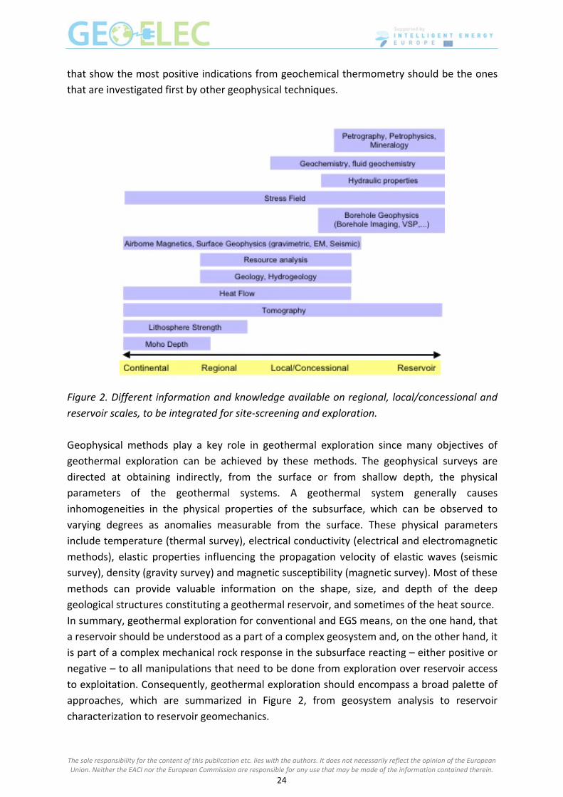
Figure 2. Different information and knowledge available on regional, local/concessional and
reservoir scales, to be integrated for site‐screening and exploration.
Geophysical methods play a key role in geothermal exploration since many objectives of
geothermal exploration can be achieved by these methods. The geophysical surveys are
directed at obtaining indirectly, from the surface or from shallow depth, the physical
parameters of the geothermal systems. A geothermal system generally causes
inhomogeneities in the physical properties of the subsurface, which can be observed to
varying degrees as anomalies measurable from the surface. These physical parameters
include temperature (thermal survey), electrical conductivity (electrical and electromagnetic
methods), elastic properties influencing the propagation velocity of elastic waves (seismic
survey), density (gravity survey) and magnetic susceptibility (magnetic survey). Most of these
methods can provide valuable information on the shape, size, and depth of the deep
geological structures constituting a geothermal reservoir, and sometimes of the heat source.
In summary, geothermal exploration for conventional and EGS means, on the one hand, that
a reservoir should be understood as a part of a complex geosystem and, on the other hand, it
is part of a complex mechanical rock response in the subsurface reacting – either positive or
negative – to all manipulations that need to be done from exploration over reservoir access
to exploitation. Consequently, geothermal exploration should encompass a broad palette of
approaches, which are summarized in Figure 2, from geosystem analysis to reservoir
characterization to reservoir geomechanics.
The sole responsibility for the content of this publication etc. lies with the authors. It does not necessarily reflect the opinion of the European Union. Neither the EACI nor the European Commission are responsible for any use that may be made of the information contained therein.
24

Relevant Publications
Oskooi, B., Pedersen, L.B., Smirnov, M., Árnason, K., Eysteinsson, H., Manzella, A., and the
DGP Working Group: The deep geothermal structure of the Mid‐Atlantic Ridge deduced
from MT data in SW Iceland. Phys. Earth Planet. Int., 150, 183‐195, 2005.
Spichak V., and Manzella A.: Electromagnetic sounding of geothermal zones, Journal of
Applied Geophysics, 68, 459–478, 2009. doi: 10.1016/j.jappgeo.2008.05.007.
The sole responsibility for the content of this publication etc. lies with the authors. It does not necessarily reflect the opinion of the European Union. Neither the EACI nor the European Commission are responsible for any use that may be made of the information contained therein.
25

Session IV – EGS technology Session IV – EGS technology J.‐D. van Wees, G. Zimmermann, P. Durst and C. Dezayes J.‐D. van Wees, G. Zimmermann, P. Durst and C. Dezayes
Presenters Presenters
Jan‐Diederik van Wees Professor, principal scientist Nederlandse Organisatie Voor Toegepast Natuurwetenschappelijk Onderzoek, TNO, Netherlands Sustainable geo‐Energy [email protected]
Günter Zimmermann Professor, principal scientist Helmholtz Centre Potsdam GFZ German Research Centre for Geosciences zimm@gfz‐potsdam.de
Pierre Durst Hydrogeologist PhD Bureau De Recherches Géologiques et Minières, BRGM, France [email protected]
Curriculum vitae Prof. Dr. Jan‐Diederik van Wees is principal scientist of geothermal research at TNO, and is extra‐ordinary professor at Utrecht University on tectonics and geothermal energy. He has published over 60 papers in leading international journals on tectonics, resource assessment, reservoir engineering, and techno‐economic models. His current research expertise focuses towards enhanced geothermal systems (EGS) and direct use applications in Europe. Van Wees serves in various co‐ordinating roles in major European and national geothermal research projects, including sub‐program management (resource assessment) in the Joint Program on Geothermal Energy of the European Energy Research Alliance. Under his leadership, TNO has developed various state‐of‐the‐art geothermal information systems and performance assessment methodologies, including thermoGIS for geothermal aquifers in the Netherlands and a decision support system for the performance assessment of enhanced geothermal systems. Further TNO is active in the EU project GEISER focused towards in depth understanding and mitigation of induced seismicity at geothermal operations.
The sole responsibility for the content of this publication etc. lies with the authors. It does not necessarily reflect the opinion of the European Union. Neither the EACI nor the European Commission are responsible for any use that may be made of the information contained therein.
26
Prof. Dr. Günter Zimmermann is professor at the Technical University of Berlin since Oct. 1, 2012 and research associate at GFZ Potsdam, at the reservoir technology section since Feb 2002. His education included Diploma in Physics, University Bonn (July 2, 1987), as well as Ph.D. (Dr. rer. nat., Sept. 12, 1991), Habilitation (Lehrbefähigung, Nov. 22, 2006) and Venia Legendi (Lehrbefugnis, Aug. 02, 2007) from the Technical University Berlin. His work experience included postdoctoral research fellow at the Technical Universities of Berlin and Braunschweig (1991‐2002) and lecturer (Oct. 1997‐Sep.2012) at the Technical University of Berlin. His research interests are in geothermal technology, hydraulic fracturing and fracture mechanics and Coupled thermal‐hydraulic reservoir modelling. Pierre Durst is a Research Scientist, who did his PhD on geochemical modelling on the Soultz‐sous‐Forêts geothermal project. He worked five years on geochemical and reservoir modelling related to CO2 storage, then four years on hydrogeological modelling related to water resources management and geothermal resources assessment. Currently he is working on geothermal resources assessment as well as on potential risks and impacts related to geothermal exploitation. Abstract
This session provides an insight into subsurface technology of Engineered Geothermal
Systems (EGS), in particular the process of hydraulic fracturing and induced seismicity in EGS
projects. Basic concepts of geomechanics and hydraulic fraccing, results of hydraulic
stimulation and induced seismicity in EGS projects will be covered by lessons learned from the
GEISER FP7 project.
The setup of this session is as follows
Part 1 theoretical background:
Basics of Rock mechanics, tectonic faulting and seismicity
Hydraulic stimulation : best practice from oil and gas, objectives and physical
principles
Part 2: EGS case studies
Enhancing flow rates
Induced seismicity
Part 3: outlook
Mitigation strategies
Best practice guidelines
Keywords: enhanced geothermal systems, hydraulic stimulation, induced seismicity
The sole responsibility for the content of this publication etc. lies with the authors. It does not necessarily reflect the opinion of the European Union. Neither the EACI nor the European Commission are responsible for any use that may be made of the information contained therein.
27
Introduction
The development of renewable energies is more urgent than ever. Geothermal energy
systems have a strong undeveloped potential in continental Europe that is estimated to be
between 10,000 and 50,000 MW. But only in the European magmatic areas in Italy, Iceland
and Portugal, production of high temperature heat (>200°C) has been harnessed for the
generation of electricity (>1,400 MW). Technological development of site‐independent
technologies to extract high temperatures at very deep levels and independent from natural
hot water resources would allow production of geothermal energy in areas which are not
marked by magmatism. There, the key is to use open fractures in high‐temperature rock so
that water and steam circulating into them can rapidly transfer heat to the Earth’s surface.
Where fractures are not naturally abundant, one needs to create new fractures or to
reactivate existing ones to increase the permeability. This can be carried out by hydraulic
stimulation, hydraulic fracturing or acidization, which all consists of injecting fluids at high
pressures in the underground. Such so‐called enhanced geothermal systems (EGS) hold the
key to future growth of geothermal energy but more experience is required to successfully
develop these systems.
Theoretical background
Tectonic stress and geomechanical properties of rocks explain jointly the process of natural
seismicity as well as the process of breaking rock by fluid injection. Natural fault motions are
characterized by shear failure resulting in earthquakes. The spatial distribution and nature of
earthquakes is strongly controlled by tectonics, the natural deformation of the earth.
Hydraulic fraccing relies on the stress state of the rock and its geomechanical properties.
Since decades tensile fraccing, marked by hardly any shear failure, is used routinely in oil and
gas to improve the performance of wells. For shale gas and EGS operations hydraulic
stimulation often involves the generating of shear fractures in order to connect wells with
permeable fractures over large distances.
EGS case studies
Most EGS projects require drilling to several kilometers depth to reach adequate
temperatures (about 120°C). In Europe, a few EGS pilots have been performed (Figure 1).
These stimulations are often accompanied by vast amounts of induced seismicity, which can
be used to characterize the reservoir, but which is also of major concern when it releases
sufficient energy to cause possible surface damage or to be felt by the population.
The sole responsibility for the content of this publication etc. lies with the authors. It does not necessarily reflect the opinion of the European Union. Neither the EACI nor the European Commission are responsible for any use that may be made of the information contained therein.
28

Figure 1. Heat flow map of Europe and geothermal projects.
In this session we present in detail the results from Soultz‐sous‐Forêts and Groß Schönebeck.
Soultz‐sous‐Forêts was Initiated in 1986, and the project has now a long history which is
broadly documented ) and benefits from a vast amount of field observations in numerous
domains (geology, geochemistry, geophysics, petrophysics, hydrogeology, etc.) gathered
during the exploration, drilling, stimulation, circulation, production phases. Today, 1.5 MWe
net power can be delivered to the French electrical network.
Over the development of the EGS, four wells have been drilled and stimulated to create the
heat exchanger prior to production. The bottoms of the holes are aligned in a N170°E
direction consistent with the horizontal principal stress direction.
At the current stage, Soultz is producing from a reservoir at around 5000m depth, at
T=190°C, with stimulations after the year 2000 in the wells GPK2, GPK3 and GPK4, circulation
tests since 2005 and the longest circulation test in 2010. From logging measurements, it has
been noticed that the reservoir consists of strongly altered granite with hydrothermally
altered and fractured zones. The hydraulic exchanger of the current Soultz reservoir is
dominated by such an altered fracture zone, which extends on large scale as a planer
structure linking GPK2 and GPK3 in the deeper reservoir.
Groß Schönebeck is developed from a reopened oil and gas well which was deepened to
4294 m depth to serve as an in‐situ geothermal laboratory. Nine months after reopening,
the bottom hole temperature was 149 °C at 4285 m depth. The reservoir of interest is
composed of sandstones, conglomerates and underlying andesitic volcanic rocks. The
sandstones constitute the principal targeted reservoir. They are well‐sorted, middle to fine
grained, with 8 to 10 % porosity and in‐situ permeability of 10 – 100 mD. In contrast to the
Dethlingen sandstone formation, the permeability of the volcanic rock is rather high due to
The sole responsibility for the content of this publication etc. lies with the authors. It does not necessarily reflect the opinion of the European Union. Neither the EACI nor the European Commission are responsible for any use that may be made of the information contained therein.
29

connected fractures. Several stimulation operations were carried out in this well at the
reservoir level to enhance water productivity and they are discussed in the next section in
parallel with the induced seismicity. To complete the doublet system of this EGS site, the
production well was drilled in 2007 down to the volcanic rocks. The stress magnitudes in the
Dethlingen sandstone at 4.1 km depth were determined to be SV=78 ‐ 100 MPa from density
logs, SH=98 MPa (at N18E) estimated from transitional form of stress regime from normal
faulting to strike slip faulting, and Sh=55 MPa from leak‐off tests in both wells. In the volcanic
section, mainly the minimal principal horizontal stress is different and is equal to Sh=72 MPa.
During stimulation, the strongest micro‐earthquakes (with Mw –1) occurred on a pre‐existing fault, which theoretically was relatively critically stressed. The strike and dip of this
fracture plane are 17°±10° and 52°±10° SE respectively.
In Soultz, Groß Schönebeck, and other pilot sites, the observed induced seismicity, spatially
lines up in relatively large and planar fault and fracture zones. Mechanical models for seismic
rupture clearly demonstrate that the geometrical and rheological alignment of these
fractures, in interaction with the pre‐existing and perturbed stress field due to hydraulic
stimulation is key to induced seismicity. Connecting to critically stressed crustal scale faults,
can ‐in theory‐ trigger relatively large events.
Outlook
The predicted contribution of EGS in the worldwide geothermal energy production portfolio
is significant for 2050. Widespread growth of EGS is anticipated after 2020 since, at that
point, easy accessible hydrothermal systems are becoming scarce. Moreover, research and
development will enable EGS to be ready for large scale deployment, both in terms of
securing public acceptance and environmental safety with regards to induced seismicity and
in terms of reducing levelized (the levelized cost of a given energy is the ratio between the
sum of all costs necessary to produce this energy over time and the production duration)
costs of energy (IEA, 2011).
In Australia and in the USA, generous funding of EGS projects provides the opportunity for
these countries to develop EGS technology. In Europe, to face these challenges, the
European Energy Research Alliance (EERA) Joint Program on Geothermal Energy (JPGE) aims
at providing an outstanding contribution bringing together 20 leading European geothermal
research institutions in a single strategically oriented joint research and development
program. The EU funds research activities partly under the umbrella of the JPGE which
includes for instance the EU project GEISER (2010‐2013) that investigates geothermal
engineering integrating mitigation of induced seismicity in geothermal reservoirs.
With an emphasis on expanding the geothermal resource base by including potential sites
for enhanced geothermal systems (EGS), engineering concepts need to be developed for a
variety of geological settings that are not normally accessed for geothermal electricity
production. As the enhancement of a geothermal reservoir involves fracturing of the
reservoir rocks, the risks of this process needs to be understood in detail to both increase
the probability of creating the enhanced flow paths for fluid circulation to make exploitation
The sole responsibility for the content of this publication etc. lies with the authors. It does not necessarily reflect the opinion of the European Union. Neither the EACI nor the European Commission are responsible for any use that may be made of the information contained therein.
30

of the reservoir economically viable and to reduce the risk of triggering earthquakes that can
be felt at the surface, disturb the public and cause damages to buildings.
It is clear that we need a more sound theoretical understanding complemented by hands on
experience in pilot projects. For these pilot projects we need guidelines for safe and reliable
EGS operations. The EU project GEISER will provide these. Key is a dynamic –forewarning‐
traffic light system. The reliability of the dynamic model comes from physics and
probabilistic based underpinning for seismicity forecasting, calibrated to geological
subsurface information and real‐time monitoring data. This approach allows adjusting
operational conditions to mitigate unsolicited effects and to improve system performance.
Further the guidelines will propose a strategy to enhance public support to EGS projects,
based on lessons learned from past projects. A cost‐benefit balance for the stakeholders
throughout the entire exploration and production workflow is important, capable of
identifying and proper addressing different interests and (perceived) risks regarding a
specific EGS project. In view of the latter, nuisance and trivial damage should be addressed
with care and considered as a significant project risk. For structural damage a procedure is
needed to evaluate and compensate the costs involved.
Relevant Publications
Cloetingh, S., Van Wees, J.D., Ziegler, P.,Lenkey, L., Beekman, F., Tesauro, M., Forster, A.,
Norden, B., Kaban, M., Hardebol, N., Bonte, D., Genter, A., Guillou‐Frottier, L., Voorde,
M.T., Sokoutis, D., Willingshofer, E., Cornu, T., Worum, G., 2010. Lithosphere tectonics
and thermo‐mechanical properties: an integrated modelling approach for Enhanced
Geothermal Systems exploration in Europe. Earth‐Science Reviews 102, 159‐206.
Bruhn, D., Huenges, E, Agustsson, K, Zang, A, , Rachez, X., Wiemer, S., Van
Wees,.J,D..Calcagno, P., , 2011. Geothermal Engineering Integrating Mitigation of
Induced Seismicity in Reservoirs ‐ The European GEISER Project. GRC transactions, 39.
Wassing, B., Van Wees, J.D., Fokker, P., 2012. , Coupled Continuum Modeling of Fracture
Reactivation and Induced Seismicity During Enhanced Geothermal Operations. ARMA
paper 12‐400.
Zimmermann, G. Blöcher, G. Reinicke, A Brandt, W. (2011): Rock specific hydraulic fracturing
and matrix acidizing to enhance a geothermal system ‐ Concepts and field results.
Tectonophysics, 503, 1‐2, 146‐154.
Zimmermann, G; Moeck, I. Blöcher, G. (2010): Cyclic waterfrac stimulation to develop an
enhanced geothermal system (EGS): Conceptual design and experimental results..
Geothermics, 39, 1, 59‐69.
Zimmermann, G. Reinicke, A. (2010): Hydraulic stimulation of a deep sandstone reservoir to
develop an Enhanced Geothermal System: Laboratory and field experiments.
Geothermics, 39, 1, 70‐77.
The sole responsibility for the content of this publication etc. lies with the authors. It does not necessarily reflect the opinion of the European Union. Neither the EACI nor the European Commission are responsible for any use that may be made of the information contained therein.
31

The Soultz projects: towards the deep geothermal exploitation
Abstract Following the general EGS technology course, this chapter is dedicated to the Soultz‐sous‐
Forêts project as the example of the deep geothermal exploitation. We will develop the 20
years scientific research to end at the application of non‐conventional geothermal
exploitation, as following:
- Concept and history: why develop the deep geothermal energy, how, the main
research projects and their contributions.
- General presentation of the Soultz project: partners, main steps of the project.
- General context: why this location, main characterisation as geology, stress field,
fluids,…
- Principle of permeability enhancing: how create thermal exchanging surfaces, which
mechanisms, result and consequences.
- Feasibility of a deep geothermal loop: development of the upper reservoir (3500m)
and the first circulation test.
- Toward the 200°C, development of the lower reservoir at 5km depth: deep wells,
production tests, tracer tests, hydraulic stimulation, induced microseismicity,
chemical stimulation, understanding of the hydraulic circulation.
- Exploitation of the 200°C: circulation test and tracer test, circulation model, pumps,
surface power plant and electrical production.
- Issues, potentiality and industrial development.
References
Dezayes C., Genter A., Valley B., 2010. Overview of the Fracture Network at Different Scales Within the Granite Reservoir of the EGS Soultz Site (Alsace, France), Proceedings World Geothermal Congress 2010, Bali, Indonesia.
Genter A., Evans K., Cuenot N., Baticci F., Dorbath L., Graff J.‐J. Sanjuan B., 2009. The EGS Soultz Project (France): From Reservoir Development to Electricity Production, GRC Transactions, Geothermal Resources Council (GRC) Annual Meeting 2009, Reno, USA.
The sole responsibility for the content of this publication etc. lies with the authors. It does not necessarily reflect the opinion of the European Union. Neither the EACI nor the European Commission are responsible for any use that may be made of the information contained therein.
32

The sole responsibility for the content of this publication etc. lies with the authors. It does not necessarily reflect the opinion of the European Union. Neither the EACI nor the European Commission are responsible for any use that may be made of the information contained therein.
33

Session V – Drilling Session V – Drilling W. Brandt W. Brandt
Presenter Presenter
Wulf Brandt
Drilling engineer, consultant
Geothermie Consulting – Engineering – Supervision,
Germany
wulf@brandt‐paetz.de
Curriculum vitae Wulf Brandt, presently drilling consultant, holds a diploma in drilling engineering and oil
production techniques of the Mining Academy of Freiberg/Germany. Since 1983 he dealt
with various aspects of utilizing geothermal energy, for example he was responsible for
opening the first East German geothermal heating system 1984 in Waren/Mueritz. He
finished his career as a scientist with GFZ Potsdam (drilling the second well and completion
of the thermal water loop Groß Schönebeck). Currently he represents the operator as senior
drilling supervisor for a geothermal doublet in the eastern foreland of the Alps. He
authored/co‐authored several technical/scientific papers.
Abstract
The contribution is focused on drilling of geothermal wells for tapping hydrogeothermal
resources and EGS with low enthalpy. Due to the low energy content of the produced
geothermal fluid – more or less mineralized water – the flow rate should be as high as
possible in order to make the project an economic success. Thus the borehole design differs
considerably from oil and gas production: larger diameters and faster temperature changes
over an extended well lifetime require an adapted approach.
Keywords: geothermal, drilling, borehole design
Introduction
In the first training course last year, Ungemach and Antics (2012) gave a broad survey on
drilling of geothermal wells both in high enthalpy reservoirs as well as into sediments utilized
for district heating systems, the latter with emphasis on well completion. The actual course
is focused to geothermal wells for power production in regions with “normal” geothermal
gradients such as the Bavarian Molasse basin and the Upper Rhine valley. Here a number of
sites with geothermal power production have been developed within the last few years (e.g.,
Soultz (EGS), Landau, Bruchsal, Unterhaching etc.). Production temperatures in the range
The sole responsibility for the content of this publication etc. lies with the authors. It does not necessarily reflect the opinion of the European Union. Neither the EACI nor the European Commission are responsible for any use that may be made of the information contained therein.
34

from 170 to 110 °C allow power production by means of the Organic Rankine or the Kalina
cycles. The naturally low efficiency of those processes requires considerably high flow rates.
Flow rate
The most productive oil well ever, “Cerro Azul No.4” in Mexico, spilled over 150000 t crude
over a radius of 3 km within one week in 1916, converting the landscape into an oil lake
(Figure 1). /http://www.sjvgeology.org/history/gushers_world.html
Figure 1. Cerro Azul blow out
Such high flow rates (here about 250 l/s) are very rare. During the spectaculous blow out of
the Macondo well (Deepwater Horizon rig) in 2010 a maximum flow rate 120 l/s has been
observed.
For reasons of comparison:
With the well GPK 2 at Soultz‐sous‐Forêts a flow rate of 30 l/s with 170 °C, represents a
usable thermal power of about 12,5 MW.
The most productive geothermal wells in Bavaria (carstic‐fractured dolomites of Jurassic age)
yield more than 150 l/s thermal water at a withdrawal of the dynamic water table below the
static one of 200…300 m. With well head temperatures of about 120…130 °C the usable
thermal power reaches the range of 30 MWth.
A reasonable and economical pipe design is based on flow velocities in the range of 2…3 m/s.
Therefore production casings in the range from 13 3/8” to 10 ¾” should be the optimum size
for the last cemented casing of such wells.
Drilling costs are in general depending of the rock volume to be destroyed. Thus reasonable
compromises will have to be found for the casing schemes of high performance geothermal
wells. So short 7 5/8” liners turn out to be the minimum acceptable dimension.
Temperature
The oil and gas industry has developed appropriate concepts to adjust casing design and
cementation to high pressure/high temperature (HPHT) borehole conditions using higher
The sole responsibility for the content of this publication etc. lies with the authors. It does not necessarily reflect the opinion of the European Union. Neither the EACI nor the European Commission are responsible for any use that may be made of the information contained therein.
35
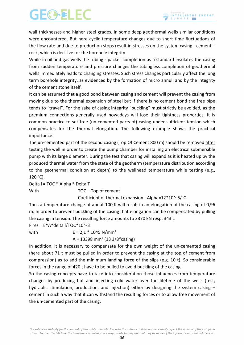
wall thicknesses and higher steel grades. In some deep geothermal wells similar conditions
were encountered. But here cyclic temperature changes due to short time fluctuations of
the flow rate and due to production stops result in stresses on the system casing ‐ cement –
rock, which is decisive for the borehole integrity.
While in oil and gas wells the tubing ‐ packer completion as a standard insulates the casing
from sudden temperature and pressure changes the tubingless completion of geothermal
wells immediately leads to changing stresses. Such stress changes particularly affect the long
term borehole integrity, as evidenced by the formation of micro annuli and by the integrity
of the cement stone itself.
It can be assumed that a good bond between casing and cement will prevent the casing from
moving due to the thermal expansion of steel but if there is no cement bond the free pipe
tends to “travel”. For the sake of casing integrity “buckling” must strictly be avoided, as the
premium connections generally used nowadays will lose their tightness properties. It is
common practice to set free (un‐cemented parts of) casing under sufficient tension which
compensates for the thermal elongation. The following example shows the practical
importance:
The un‐cemented part of the second casing (Top Of Cement 800 m) should be removed after
testing the well in order to create the pump chamber for installing an electrical submersible
pump with its large diameter. During the test that casing will expand as it is heated up by the
produced thermal water from the state of the geotherm (temperature distribution according
to the geothermal condition at depth) to the wellhead temperature while testing (e.g.,
120 °C).
Delta l = TOC * Alpha * Delta T
With TOC – Top of cement
Coefficient of thermal expansion ‐ Alpha=12*10^‐6/°C
Thus a temperature change of about 100 K will result in an elongation of the casing of 0,96
m. In order to prevent buckling of the casing that elongation can be compensated by pulling
the casing in tension. The resulting force amounts to 3370 kN resp. 343 t.
F res = E*A*delta l/TOC*10^‐3
with E = 2,1 * 10^5 N/mm²
A = 13398 mm² (13 3/8“casing)
In addition, it is necessary to compensate for the own weight of the un‐cemented casing
(here about 71 t must be pulled in order to prevent the casing at the top of cement from
compression) as to add the minimum landing force of the slips (e.g. 10 t). So considerable
forces in the range of 420 t have to be pulled to avoid buckling of the casing.
So the casing concepts have to take into consideration those influences from temperature
changes by producing hot and injecting cold water over the lifetime of the wells (test,
hydraulic stimulation, production, and injection) either by designing the system casing –
cement in such a way that it can withstand the resulting forces or to allow free movement of
the un‐cemented part of the casing.
The sole responsibility for the content of this publication etc. lies with the authors. It does not necessarily reflect the opinion of the European Union. Neither the EACI nor the European Commission are responsible for any use that may be made of the information contained therein.
36

Tie back strings are common to connect a liner hanger to the surface, e.g. to protect the
upper casings from unduly high internal pressures during stimulation jobs. Here a piston seal
is moving within the polished bore receptacle on top of the liner hanger.
For the wells at Soultz‐sous‐Forêts that principle has been applied to the well head – the free
casing (not imposed to buckling by its design) moves in a stuffing box situated within the
cellar (see Figure 2).
Figure 2. Casing design Soultz‐sous‐Forêts /Tischner et al., 2006
The un‐cemented part of the hole is formed by solid rock belonging to a uniform
hydrogeological section.
Heating up of geothermal wells during production does not only affect the casing elongation
but it can cause considerable damage by the expansion of water or mud trapped behind the
casing if it cannot escape into the surrounding rock.
Often the resulting external pressure exceeds the resistivity of the casing resulting in an
unexpected casing collapse.
Casing design and geological conditions
The site related geological knowledge is crucial with regard to cost effective drilling and the
prevention of drilling troubles. The following principles are mandatory:
Define casing setting depths to allow for a maximum stability of the preceding drilling
section.
The sole responsibility for the content of this publication etc. lies with the authors. It does not necessarily reflect the opinion of the European Union. Neither the EACI nor the European Commission are responsible for any use that may be made of the information contained therein.
37

Eliminate strongly different formation pressure gradients within drilling phases since
differential sticking can cause costly fishing operations or even endanger the whole
well.
Some formations require special mud systems such as salt layers, or should be
protected for other reasons by setting the casing as soon as possible.
Separation of formations against circulation or gas migration behind the casing
Casing – bit combinations
The industry offers a broad selection of casing dimensions and of bits as well. But it is worth
mentioning that certain combinations of casings have been ruled out as “standards” with
short time availability not only for pipes but also concerning float equipment, liner hangers,
packers etc. If it is necessary to change to “exotic” dimensions (including features like
“special drift” and “special clearance” the designing engineer must check that all necessary
equipment will be available in due time. A useful survey on possible casing‐bit‐combinations
is shown in Figure 3.
To overcome those constraints generally ongoing R&D at Baker Hughes INTEC GmbH, for
example, is directed to combinations of conventional borehole design with expandable liner
techniques or even to the creation of monodiameter boreholes (see Figure 4).
Case histories of drilling 4000…5000 m deep geothermal wells are content of the oral
presentation.
References
Ungemach, P., Antics, M., 2012 Geothermal well drilling. Schütz, F. and A. Spalek (eds.), in
Manual of the First Training Course on Geothermal Energy, 5‐9 November 2012,
Strasbourg, France, pp. 12‐17.
Tischner et al., 2006 Hot Dry Rock Projekt Soultz: Erste Phase der Erstellung einer
wissenschaftlichen Pilotanlage, Abschlussbericht, BGR und BESTC GmbH 2006.
Barker 1998, quoted in Sperber,A., Moeck, I.; Brandt, W. Drilling into Geothermal reservoirs.
Huenges,E. (ed.) Geothermal Energy Systems Exploration, Development, and Utilization,
Wiley‐VCH Verlag GmbH&Co. KGaA, Weinheim 2010.
Oppelt, J. Geothermie und innovative Bohrtechnik. Vortrag Geozentrum Hannover
Geothermietag 30. Oktober 2008.
http://www.sjvgeology.org/history/gushers_world.html.
The sole responsibility for the content of this publication etc. lies with the authors. It does not necessarily reflect the opinion of the European Union. Neither the EACI nor the European Commission are responsible for any use that may be made of the information contained therein.
38

Figure 3. Casing ‐ bit – combinations /Barker, 1998
The sole responsibility for the content of this publication etc. lies with the authors. It does not necessarily reflect the opinion of the European Union. Neither the EACI nor the European Commission are responsible for any use that may be made of the information contained therein.
39
Figure 4. Borehole design with expandables /Oppelt, 2008
The sole responsibility for the content of this publication etc. lies with the authors. It does not necessarily reflect the opinion of the European Union. Neither the EACI nor the European Commission are responsible for any use that may be made of the information contained therein.
40

The sole responsibility for the content of this publication etc. lies with the authors. It does not necessarily reflect the opinion of the European Union. Neither the EACI nor the European Commission are responsible for any use that may be made of the information contained therein.
41

Session VI – Flash steam and binary technology Session VI – Flash steam and binary technology E. Hallgrímsdóttir and P. Bombarda E. Hallgrímsdóttir and P. Bombarda
Presenters Presenters Elín Hallgrímsdóttir
Mechanical Engineer M.Sc., Mannvit, Iceland Energy Department, Project Management [email protected]
Paola Bombarda
Lecturer, PhD, Politecnico di Milano [email protected]
Curriculum vitae
Mrs. Elín Hallgrímsdóttir is a Mechanical Engineer, MSc, from Danmarks Tekniske Universitet
in 1998. Mechanical Engineer, CandSc, from University of Iceland 1996. Mrs Elín
Hallgrímsdóttir has experience within thermodynamics and process engineering as well as
project management and quality systems. Mrs Hallgrímsdóttir has participated as assistant
project manager and senior designer within numerous projects in Mannvit such as in the
Nesjavellir and Hellisheidarvirkjun geothermal combined heat and power projects. Mrs
Hallgrímsdóttir held the position of Mannvit project manager in a feasibility study for
KenGen in Kenya. Mrs Hallgrímsdóttir has further given presentations on geothermal energy
for short courses held by Mannvit.
Dr. Paola Bombarda has a PhD in Energetics ‐1994 and MSc Degree in Mechanical
Engineering ‐1990, both from Politecnico di Milano (I) and is Assistant Professor of “Energy
and Environmental Systems” at Politecnico di Milano since 1995. She has a deep knowledge
in thermodynamic analysis of energy systems for power generation, cogeneration,
trigeneration and plant performance optimization, with specific interest in renewables and
above all in geothermal energy. She has gained wide experience in modeling, simulation,
thermodynamic analysis and optimization of geothermal power plants (dry steam and flash,
binary, hybrid plants) for which she also tackled techno‐economic analysis and electric
energy cost estimation. Particular expertise is acquired for ORC plants. Research activity is
devoted also to the study and analysis of complex energy systems including geothermal heat
pumps. Participant to several national and European research projects on geothermal
energy and energy systems. Lecturer for the subject “Geothermal energy” in the frame of
the master RIDEF at Politecnico di Milano. She contributed with papers and presentations to
the main international geothermal Conferences.
The sole responsibility for the content of this publication etc. lies with the authors. It does not necessarily reflect the opinion of the European Union. Neither the EACI nor the European Commission are responsible for any use that may be made of the information contained therein.
42

Abstract
This is an overview of geothermal power plants with focus on flash and binary
thermodynamic cycles, geothermal steam gathering system and mechanical equipment used.
Further provided examples highlight special features of utilizing geothermal fluid for power
generation. The examples taken are connected to the special conditions encountered in
geothermal energy.
Flash steam cycles with single flash and double flash as well as different binary cycles as ORC
and Kalina Cycle are introduced and compared. Models for different thermodynamic cycles
are used to calculate the same example for visual comparison of the different cycles.
An overview of the design process of a geothermal steam gathering system with emphasis on
particularities of the geothermal fluid is presented. The presenter goes through a calculated
example to show methods used for basic engineering within steam gathering system design.
A presentation will focus on mechanical equipment used in geothermal power plants.
Emphasis will be on different design considerations compared to conventional steam plants.
A calculated example will show methods used for basic engineering within mechanical
equipment design.
Operation and maintenance of geothermal power plants with emphasis on the geothermal
part of the plant is introduced. Photographs of extreme conditions are discussed with
solutions.
Keywords: Geothermal energy, electricity generation, process flow, binary technology,
steam gathering system, operation and maintenance
Process flow and steam gathering system
Geothermal power plants utilize heat energy from the Earth to generate electricity and can
also be designed to generate combined heat and power (CHP). They are cost effective,
reliable and environmentally friendly. The specific geothermal power plant configurations
must match the heat resource to maximize its potential but should also take into account a
variety of other criteria including, local conditions and requirements as well as the needs of
the local community. Thermodynamic cycles used in geothermal energy production will be
reviewed with examples. Flash steam cycles with single flash and double flash as well as
different binary cycles as ORC and Kalina Cycle are introduced and compared through both
capacity and cost.
An overview of the design process of a geothermal steam gathering system with emphasis
on particularities of the geothermal fluid is presented. Models for different thermodynamic
cycles will be used to calculate the same example for visual comparison of the different
cycles.
The sole responsibility for the content of this publication etc. lies with the authors. It does not necessarily reflect the opinion of the European Union. Neither the EACI nor the European Commission are responsible for any use that may be made of the information contained therein.
43

Figure 1. Process Flow Diagram of Steam Power Plant with Condenser
Figure 2. Steam field of Hellisheiði Power Plant
All geothermal fields are unique and the steam gathering system carries the energy from the
field to the power plant. To join multiple wells into one steam gathering system requires for
example decision of optimum separator pressure. The presenter will go through a calculated
The sole responsibility for the content of this publication etc. lies with the authors. It does not necessarily reflect the opinion of the European Union. Neither the EACI nor the European Commission are responsible for any use that may be made of the information contained therein.
44

example to show methods used for basic engineering within steam gathering system design.
The example taken will be connected to the special conditions encountered in geothermal
energy.
The steam field design includes situating wells drilled in groups as appropriate. Wells are
preferably situated higher in the landscape than the separator station and power station. If
possible the power station should be situated a little lower than the separator station. This is
preferred to facilitate natural fluid flow. The distance between separation station and mist
separators should be selected long enough for the moisture to condensate in the pipeline
before entering the mist separators.
When the geothermal fluid is two phase, and steam represents a low fraction of it, or the
geothermal fluid is fully constituted by water, typically with medium‐low temperature
sources, the binary technology is applied, and generally a downhole pump (i.e. a pump
installed directly in the well) is required. The geothermal fluid loop is in this case completely
separated from the power generation cycle; the adoption of the downhole pump, though
requiring a high auxiliary power consumption, can assure a constant discharge flow at a
convenient pressure, so as to keep the geothermal fluid in liquid phase, avoiding any flash
process. In this way two important results are obtained: all the non‐condensable gases
(mostly CO2) are maintained in the liquid phase, and, salt precipitation, which could
otherwise occur after the flash process, both downhole and on surface, is strongly reduced.
Geothermal fluid leakage can be effectively avoided, because the fluid is confined in a
limited part of the plant, and total reinjection is then feasible, thus leading to a virtual zero
emission plant and sustainable reservoir exploitation.
The power generation cycle is a closed cycle, whose design guidelines relies on fundamental
thermodynamic principles, is realized by means of a convenient working fluid. The easiest
possible scheme is shown in Figure 3.
The working fluid evaporation occurs in the evaporator, the heat exchanger charged with
heat introduction; the vapour so generated enters afterwards the turbine, which is charged
with power generation; subsequently the vapour condenses in the condenser, the heat
exchanger charged with heat rejection to the ambient, and finally the condensate enters
into the pump, which is charged with working fluid pressurization.
The working fluid selection is a crucial choice: being the cycle closed, whatever working fluid
can be selected, but this choice has a huge effect on plant performance and component size,
and thus cost.
The two different categories of binary cycles commonly available, Organic Rankine Cycles
(ORC) and Kalina cycles, differentiate as far as the working fluid is concerned: in ORC a pure
working fluid, (or seldom an azeotropic mixture) is utilized, while in Kalina cycle and Kalina
derived cycles, a mixture of water and ammonia is selected.
At present, most commonly used working fluids for ORC geothermal applications are some
hydrocarbons and refrigerants (several refrigerants are non flammable or flammable only
under extreme ignition conditions, and are therefore particularly eligible when non–
flammability is desired; other fluids, like siloxanes, may be selected at higher temperatures,
as, for example, for biomass applications). As a first, general rule of thumb, the working fluid
The sole responsibility for the content of this publication etc. lies with the authors. It does not necessarily reflect the opinion of the European Union. Neither the EACI nor the European Commission are responsible for any use that may be made of the information contained therein.
45

must be selected according to its critical temperature and the temperature of the
geothermal source.
Figure 3. Binary plant scheme
The heat introduction process, which implies the working fluid phase change, has a high
influence on the cycle efficiency: with a pure (or azeotropic) fluid the phase change process
in subcritical conditions is at constant temperature and pressure (Figure 4, top, left), with a
mixture, instead, the phase change process occurs at constant pressure and variable
temperature (Figure 4, top, right). If the hot thermal source is a variable temperature heat
source, (which is the case for the geothermal source) a phase change process at variable
temperature can better match the geothermal source, as shown in Figure 4; it can also be
noted from Figure 4 that heat introduction at variable temperature is also obtainable by
means of a cycle with pure fluid, multiple pressure evaporation (Figure 4, bottom. left) or
supercritical cycle (Figure 4, bottom, right).
The sole responsibility for the content of this publication etc. lies with the authors. It does not necessarily reflect the opinion of the European Union. Neither the EACI nor the European Commission are responsible for any use that may be made of the information contained therein.
46

Figure 4. Heat introduction process in case of a) pure fluid b) mixture, c) pure fluid, multiple
evaporation pressure, d) pure fluid, supercritical pressure
Most of the existing geothermal binary plants are ORC with single pressure evaporation, but
all the technical options shown in Figure 4 are available on the market; high efficiency plant
configurations will be of great interest in the future, above all in Europe (techno‐economic
optimization with high drilling cost leads in fact to high binary plant specific cost, in order to
fully exploit the source)
In order to give the best possible performance, the selected thermodynamic cycle need to
be optimized, also taking into account scaling hazard, which may limit the cooling of the
geothermal fluid. Need for an optimization process can be understood e.g. referring to the
single evaporation pressure cycle: a too high evaporation pressure would lead to a high cycle
efficiency but also to a poor heat introduction in the cycle, and vice versa for a too low
evaporation pressure.
In some cases the cycle efficiency may be improved by means of an internal heat transfer,
occurring in a recuperator. (Figure 5); this happens when the working fluid is such that the
end point of the expansion process falls into the superheated vapour region, and therefore
the vapour can be profitably cooled (thus heating the liquid coming from the pump) prior to
enter the condenser.
The sole responsibility for the content of this publication etc. lies with the authors. It does not necessarily reflect the opinion of the European Union. Neither the EACI nor the European Commission are responsible for any use that may be made of the information contained therein.
47

Figure 5. Binary plant with recuperation
When using a mixture as working fluid, i.e. with Kalina cycles, the composition may be
changed throughout the plant with the aid of separators and mixers (Figure 6); several
recuperators (heat exchangers charged with internal heat transfer) could also be
appropriate; as a result, different plant scheme exist and some of them are quite
complicated.
Figure 6. Kalina plant scheme
The sole responsibility for the content of this publication etc. lies with the authors. It does not necessarily reflect the opinion of the European Union. Neither the EACI nor the European Commission are responsible for any use that may be made of the information contained therein.
48

The cycle efficiency depends on (i) geothermal source and ambient conditions and (ii) cycle
design features: the influence of the geothermal source and ambient conditions can be
understood recalling that for the reference ideal cycle holds
The ambient temperature is variable according to the site, but in a rather limited range,
while the geothermal source temperature may have a larger variation: as a matter of facts
(Figure 7), existing binary plant efficiencies are comprised between 0.05 and 0.15; higher
efficiencies are expected for plants fed by higher temperature geothermal sources.
Figure 7. Binary plant efficiencies
Plant balance must be finally considered, detracting auxiliary consumption (mainly downhole
pump and cooling auxiliaries) from the calculated net cycle power.
Finally, in case the geothermal source is two phase, plants which comprise a steam section
and one or more binary section can also be realized: this kind of plant allows the highest
geothermal source exploitation.
The sole responsibility for the content of this publication etc. lies with the authors. It does not necessarily reflect the opinion of the European Union. Neither the EACI nor the European Commission are responsible for any use that may be made of the information contained therein.
49

Figure 8. Mixed steam/binary plant
Cascade use / cogeneration schemes are also feasible, as well as hybrid plants using the
geothermal source in addition to another thermal source (e.g. solar or biomass or wastes).
Mechanical equipment and operation and maintenance
Mechanical equipment used in geothermal power plants are proven traditional equipment
adjusted to the geothermal fluids. Emphasis within the course will be on different design
considerations compared to conventional steam plants such as geothermal turbine sizes and
control solutions at turbine inlet connected to operation of the geothermal steam field.
Choice of material for geothermal turbines has to be adjusted to the available steam and is
therefore different from material in traditional steam turbines. Non‐condensable gases must
be considered and removed from the condenser by means of a proper system since they
would otherwise accumulate in the condenser. The steam entering the turbine is saturated
and therefore, the steam starts to condense in the turbine. As a result droplets form in the
flow and the droplets wear down the turbine blades. To decrease the amount of droplets in
the flow, it is important to carefully design lead ways for the condensate in the turbine.
Scaling may also occur especially at the first‐stage nozzle nearest the turbine inlet leading to
reduced generator output. Scaling can impact the effectiveness of the guide vanes. Scaling is
removed during regular turbine maintenance.
The presenter will go through a calculated example to show methods used for basic
engineering within mechanical equipment design. The example taken will be connected to
the special conditions encountered in geothermal energy.
The sole responsibility for the content of this publication etc. lies with the authors. It does not necessarily reflect the opinion of the European Union. Neither the EACI nor the European Commission are responsible for any use that may be made of the information contained therein.
50

In this session operation and maintenance of geothermal power plants with emphasis on the
geothermal part of the plant is introduced. Photographs of extreme conditions will be shown
and discussed with solutions.
Figure 9. Machine hall of Hellisheiði Power Plant
Figure 10. Scaling and corrosion in turbine casing
The sole responsibility for the content of this publication etc. lies with the authors. It does not necessarily reflect the opinion of the European Union. Neither the EACI nor the European Commission are responsible for any use that may be made of the information contained therein.
51

A binary plant consists of several heat exchangers, a multistage centrifugal pump and a
turbine.
Different kind of heat exchangers (e.g. shell & tubes, plates) are eligible. Depending on the
flow specific conditions: possible corrosion on the side of the geothermal fluid oblige to
adopt special and costly materials for the heat exchangers, with a great influence on the cost
of the unit, and possible scaling and fouling require removable covers and straight cleanable
tubes.
The pump is usually operated at variable speed, so that greater flexibility and efficiency are
achieved. Axial flow turbines are most widely used in ORC plants: organic fluids exhibit
usually low enthalpy drop during expansion, and a small single stage turbine, (or, if needed,
a few stages turbine) is commonly appropriate. In most of the existing plants the turbine
rotates at 3000 rpm, though recently faster (coupled to a variable speed electric generator)
and smaller turbines have also been employed. The adoption of radial turbines has also been
proposed: it must be pointed out that both radial inflow and radial outflow turbines have
been considered. The radial inflow scheme allows larger work per stage and moreover,
partial admission vanes can be easily accommodated; radial outflow scheme consents a
small work per stage (several stages are then needed) but tolerates high variations of the
volumetric flow between the inlet and outlet of the turbine.
Most of the problems encountered with steam turbine are not present with binary turbines:
in ORC plants, the selected working fluid is not chemically aggressive, and it is usually such
that the expansion ends in the superheated vapor region, thus preventing the turbine blades
from droplets erosion; moreover the turbine is subjected to low mechanical stress due to
the low peripheral speed. In Kalina cycle based plants, the working fluid is toxic and
corrosive, and particular attention is to be paid for possible leakages. As a whole, limited
O&M requirements and long life are typical for binary plants.
Relevant Publications
Hallgrímsdóttir E., Ballzus C. and Hrólfsson H. (2012); “The Hellisheiði Power Plant, Iceland.”
GRC transaction, Volume 36, page 1067 ̶ 1072. Angelino G., Bini R., Bombarda P., Gaia M., Girardi P., Lucchi P., Macchi E., Rognoni M.,
Sabatelli F., "One MW binary cycle turbogenerator module made in Europe", " World
Geothermal Congress", Firenze, 1995.
Bombarda, P., Duvia, A., Macchi, E., "Combined, Mixed and Binary cycles for electricity
Generation from Geothermal Sources ‐ part A: selected configurations and calculation
model", Proceedings of "The 20th New Zealand Geothermal Workshop", pp. 347‐352, ",
Geothermal Institute, The University of Auckland, 1998, Nuova Zelanda ISBN 0‐86869‐
083‐X.
Bombarda, P., "Combined, Mixed and Binary cycles for electricity Generation from
Geothermal Sources ‐ part B: technical economic analysis ", Proceedings of "The 20th
New Zealand Geothermal Workshop", pp. 353‐358, Geothermal Institute, The
University of Auckland, 11‐13 novembre 1998, Nuova Zelanda ISBN 0‐86869‐083‐X.
“Best Engineering Paper”.
The sole responsibility for the content of this publication etc. lies with the authors. It does not necessarily reflect the opinion of the European Union. Neither the EACI nor the European Commission are responsible for any use that may be made of the information contained therein.
52
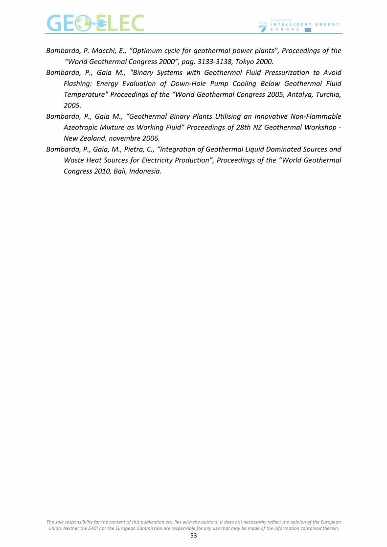
Bombarda, P. Macchi, E., “Optimum cycle for geothermal power plants”, Proceedings of the
“World Geothermal Congress 2000”, pag. 3133‐3138, Tokyo 2000.
Bombarda, P., Gaia M., "Binary Systems with Geothermal Fluid Pressurization to Avoid
Flashing: Energy Evaluation of Down‐Hole Pump Cooling Below Geothermal Fluid
Temperature" Proceedings of the “World Geothermal Congress 2005, Antalya, Turchia,
2005.
Bombarda, P., Gaia M., “Geothermal Binary Plants Utilising an Innovative Non‐Flammable
Azeotropic Mixture as Working Fluid” Proceedings of 28th NZ Geothermal Workshop ‐
New Zealand, novembre 2006.
Bombarda, P., Gaia, M., Pietra, C., “Integration of Geothermal Liquid Dominated Sources and
Waste Heat Sources for Electricity Production”, Proceedings of the “World Geothermal
Congress 2010, Bali, Indonesia.
The sole responsibility for the content of this publication etc. lies with the authors. It does not necessarily reflect the opinion of the European Union. Neither the EACI nor the European Commission are responsible for any use that may be made of the information contained therein.
53

Session VII – Plant operation, energy supply and grid integration Session VII – Plant operation, energy supply and grid integration F. Heilemann and S. Reith F. Heilemann and S. Reith
Presenters Presenters
Franz Heilemann Dr.‐Ing., Senior Manager EnBW Energie Baden‐Württemberg Regional AG, Germany [email protected]
Sören Reith EnBW AG (Research & Development), Research & Development
Curriculum vitae
Dr.‐Ing. Franz Heilemann is experienced in planning, construction and operation of electricity
grids on all voltage levels. The development of interdisciplinary smart grid strategies with
integration of renewables and customers as well as economic analyses, efficiency
benchmarks and regulatory management are part of his work at the network operator EnBW
Regional AG. His dissertation at the University of Stuttgart was focused on stability problems
of large interconnected power systems and their improvement.
Sören Reith did his Bachelor at the Baden‐Wuerttemberg Cooperative State University
Karlsruhe (DHBW), followed by his Master at the Karlsruhe Institute of Technology (KIT),
which he finished in 2011. Parallel to his studies he was working in different departments of
EnBW. Since 2009 he gathered experience in the research and development department of
EnBW. Currently he is working on his doctoral thesis in the field of deep geothermal energy
production in cooperation with the University of Stuttgart.
Abstract
The integration of electricity from geothermal power plants into the electricity grid has to be
seen from different perspectives. In the following the legal aspects and the function of the
regulated energy market are explained as well as demand for geothermal power and the
process, the costs and the legal background of grid integration. This gives the reader a broad
understanding of the main foundations for grid integration of geothermal electricity. Based
on regulated energy markets different legal systems in Europe support the integration of
renewable power into the market, which is met by a growing demand for renewable power in
general and geothermal power in particular. The growing share of renewable power causes
problems in grid stability. That’s why besides legal also technical requirements determine the
process of grid integration. The costs for grid integration are very site specific and are
determined by the network connection point and the installed capacity of the power plant.
The sole responsibility for the content of this publication etc. lies with the authors. It does not necessarily reflect the opinion of the European Union. Neither the EACI nor the European Commission are responsible for any use that may be made of the information contained therein.
54

Keywords: grid integration; costs of grid integration; energy market; electricity grid
Regulation and energy trade Electricity supply has developed since its beginnings in the late 19th century in monopolistic
structures. Because of expensive infrastructure and its associated economic advantages of a
monopole, vertically integrated energy suppliers got the task of supplying the public and the
industry with electricity.
With the electricity market directive 96/92/EG the European Union has changed this
monopolistic market structure. The goal of this directive was free trade and competition on
the electricity market (Konstantin, 2007, S. 37). Since then several other EU directives and
decisions have brought European wide energy trade and the possibility for every customer
to choose its electricity supplier. Part of this is the free access to the electricity grid. Several
European and national political requirements like for example the so called unbundling,
which means the legal separation of production, transport and distribution, shall give every
user a fair, transparent and equal access to the electricity network (European Parliament and
the Council, 2003, Art. 7‐9).
In the liberalised energy markets, electricity became a trade product which is similar to
shares or other commodities traded over a stock exchange or in bilateral contracts. Bilateral
or the so called over‐the‐counter trade is a classical contract between two parties, which
negotiate price, amount and time of delivered electricity. However, trading over the stock
exchange works with standardized products. The products are characterized by the period of
supply (hours or time periods) and are offered in €/MWh. As a reference for energy prices
the spot‐market is used. Here suppliers and buyers of electricity can put their offer and
demand requests in an anonymous order book. At 12 o’clock the order book is closed for the
following day. Demand and offers are merged in a merit order, where the most expensive
power plant which is needed to satisfy the demand sets the price.
Besides the free electricity trade, renewable electricity is in many countries supported by
different federal programmes. With the Electricity Feed‐in Act (StrEG) Germany started 1991
to support renewable energies with feed‐in‐tariffs and the legal obligation for grid operators
to connect renewable capacity to the electricity grid (BRD, 1990). 2000 the “Renewable
Energy Act (EEG)” has replaced this act and has introduced geothermal energy into the
federal support mechanism. Similar regulations also exist in other European countries for
example France. Since 2000 the “Loi n°2000‐108” supports renewable energy sources (RES)
with feed‐in‐tariffs, an obligation for the grid connection and special tenders for renewable
energies (BMU, 2011).
Electricity Grid
The natural monopole of the electricity grid is strongly regulated. National regulation
authorities monitor the discrimination free access and the cost efficient operation of the
networks. The operators are paid for their effort by network‐use fees. These fees at least
have to be made public. In Germany the authority in charge approves them with a
The sole responsibility for the content of this publication etc. lies with the authors. It does not necessarily reflect the opinion of the European Union. Neither the EACI nor the European Commission are responsible for any use that may be made of the information contained therein.
55

benchmark system, which takes among others the geographical differences into account
(Konstantin, 2007).
The integrated European electricity grid enables a secure electricity supply in Europe by
connecting numerous power plants. This redundancy leads on the one hand to a secure and
efficient power supply; on the other hand long distances have to be bridged. The
transported power is the key parameter for the network design. The power can be
calculated with . As the current is limited by the heat resistance of the wire, the
voltage is the only parameter, which can be adapted to the power demand. This
fundamental law of electricity transport leads to the insight, that different network levels
are necessary for different transport tasks.
Figure 1. Schematic diagram integrated network (own illustration based on Konstantin, 2007,
S. 330)
The sole responsibility for the content of this publication etc. lies with the authors. It does not necessarily reflect the opinion of the European Union. Neither the EACI nor the European Commission are responsible for any use that may be made of the information contained therein.
56

Figure 1 gives an overview of the different network levels. The electricity of big power plants
(>300 MW) is feed into the extra high voltage grid. This grid level transports the electricity
over long distances to consumption centres. The long distances make an extra high voltage
of up to 380 kV necessary. Transformer stations transform the electricity to 110 kV (High
Voltage). This level is used to distribute electricity to regional consumption centres or large
industrial companies. The next step is to transform the electricity to the middle voltage level
(10 – 30 kV), which supplies districts, bigger cities and industrial sites. Residential buildings
and small businesses are finally connected to the grid by the low voltage level with 400V
(Konstantin, 2007, S. 331).
Geothermal power plants (single power plants in a complex) in high enthalpy regions like
Italy or Iceland deliver up to 750 MW or more. These power plants usually feed their
electricity direct into the high or extra high voltage level. In low enthalpy areas like Germany
typical geothermal power plants have an installed capacity of 1 ‐ 5 MW, which means that
they are connected to the medium voltage grid.
Demand for geothermal power
The European Union has set itself ambitious goals for becoming a high‐efficiency, low carbon
economy. Until 2020 20% of the energy consumption shall be met with renewable energy.
Additionally CO2‐emissions shall be cut by 20 % and the energy efficiency shall be increased
by 20 % (European Commission, 2012). Geothermal energy is defined under German law as a
renewable energy source and is needed to achieve these goals (BRD, 2012, § 3; 3).
Geothermal electricity in Germany has a technical potential of nearly 300 TWh/a and can so
contribute to renewable energy generation (Paschen, Oertel, & Grünwald, 2003). 300 TWh/a
would be ~ 60 % of the annual German electricity demand (based on 2010) (BMWi, 2012).
Currently there are 10.7 GWel of geothermal capacity installed worldwide. Germany has with
7.3 MWel only a small share in this capacity. Until 2020 the German government predicts an
installed capacity of ~ 200 MWel while the German renewable Energy federation expects up
to 470 MWel (Geothermie Bundesverband). The high availability of geothermal power plants
also contributes to the demand for geothermal energy. Geothermal power plants have one
of the highest capacity factors1 of all electricity production technologies. With ~ 90 %
geothermal power plants have a capacity factor which is as high as the capacity factor of
nuclear power plants (Tidball, Bluestein, Rodriguez, & Knoke, 2010). This makes geothermal
power besides hydropower one of the only renewable power plants which are suitable for
base load. Beside the electricity production it is possible to use geothermal power as a heat
source for district heating. Geothermal power plants can so be used as combined heat and
power source. This improves the efficiency of the power plant as well as the economic
situation.
1 full-load ratio of a power station per annum
The sole responsibility for the content of this publication etc. lies with the authors. It does not necessarily reflect the opinion of the European Union. Neither the EACI nor the European Commission are responsible for any use that may be made of the information contained therein.
57

Grid integration of an increasing share of renewable power generation – challenges for the
network and system operation
The European 20‐20‐20 energy and climate targets, particularly the enormous increase of
renewable generation will have a huge impact on both, the transmission and the distribution
network as well. This becomes not only a question of balancing the power according to the
equilibrium of generation and consumption and therewith the frequency control from the
viewpoint of the Transmission System Operator (TSO), but becomes even more challenging
for the Distribution System Operator (DSO). He has to deal with local and regional reverse
load flow conditions, voltage problems and the overloading of lines. This can be summarized
in the task of managing the system in a secure and cost efficient manner.
How dramatic the future development could be, illustrates the situation in Germany.
Currently the system peak load amounts to nearly 80.000 MW. To reach the intended target
of a 35% share of renewables in 2020 the capacity of installed renewables alone will be as
high as the maximum peak load. In addition the priority feed‐in of RES, the volatility and the
intermittent generation will cause substantial problems for system stability in the West
European Interconnection2 as well as supply problems in the local areas of the DSO where
renewables are connected to the grid. To meet these challenges a massive grid expansion
and a frequent use of balancing power are necessary, which is associated with considerable
costs.
A paradigm shift in the sense that load follows generation is needed. The incorporation of
the customer and the development of smart grids with highly complex, real time
communication systems to adapt generation and consumption and to realize an optimal use
of network assets in a secure and cost efficient manner will be inevitable. That’ll lead to
additional and new requirements for decentralized power plants based on renewable
feeding. For the medium and high voltage levels it’ll be necessary to implement a load and
generation management system to be able to operate the system effectively while keeping
the quality standards and to optimize the connection capacity for RES in case of given
network assets.
Costs of grid integration
To ensure a secure and reliable network operation network operators have specified
requirements for the network connections of RES. An additional boundary condition for the
grid connection in Germany is the incentive regulation for DSOs, which was introduced by
the Federal Network Agency (BNetzA). DSOs are obligated to connect power plants in total
(costs for DSO and power plant operator (PPO)) as cost efficient as possible. The most
important point in the question of cost allocation is the network connection point (NCP).
Objectives and transparent criteria to determine the NCP are given by law and regulations.
This point marks the border of property, the responsibility for assets and defines the cost
allocation between the PPO and the DSO.
2 European transmission network
The sole responsibility for the content of this publication etc. lies with the authors. It does not necessarily reflect the opinion of the European Union. Neither the EACI nor the European Commission are responsible for any use that may be made of the information contained therein.
58
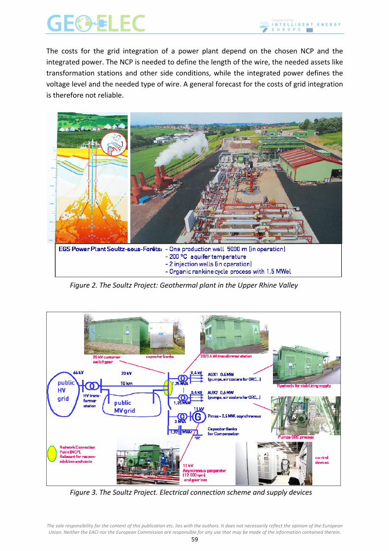
The costs for the grid integration of a power plant depend on the chosen NCP and the
integrated power. The NCP is needed to define the length of the wire, the needed assets like
transformation stations and other side conditions, while the integrated power defines the
voltage level and the needed type of wire. A general forecast for the costs of grid integration
is therefore not reliable.
Figure 2. The Soultz Project: Geothermal plant in the Upper Rhine Valley
Figure 3. The Soultz Project. Electrical connection scheme and supply devices
The sole responsibility for the content of this publication etc. lies with the authors. It does not necessarily reflect the opinion of the European Union. Neither the EACI nor the European Commission are responsible for any use that may be made of the information contained therein.
59

The integration of a power plant therefore has to be investigated site specific. As an example
Figure 3 shows the connection scheme for the geothermal power plant in Soultz‐sous‐Forêts
(France) (see Figure 2).
The connection to the public grid lies very close to the power plant so that routing costs
could be kept to a minimum. The costs for the equipment obviously depend on the
requirements of the power plant. For the geothermal power plant in Soultz the costs of main
parts of the electrical equipment are given in Table 1.
Table 1. Grid integration costs at the Soultz EGS power plant
Generation Transformer 46,000 €
Switchgear 68,000 €
Auxiliaries Transformer 93,000 €
Switchgear 112,000 €
Compensation Capacitor banks 24,000 €
Connection devices (general) Medium voltage lines/cables 70 – 120 €/m
Medium/low voltage substation 30,000 € ‐ 50,000 €
High/medium voltage transformer station 1 – 1.5 Mil. €
Process of grid integration
Basis for the determination of an appropriate NCP for the connection of the power plant is
the information provided by the PPO. Criteria are the maximum real power Pmax and the
apparent power Smax of the plant as well as its location and the request for connection. This
enables the DSO by means of network calculations to determine the appropriate NCP.
Usually the local network operator provides checklists, requirements, technical regulation
and conditions for the connection and commissioning of the decentralized generation units.
In this process the metering concept and the telecommunication devices also need to be
specified. Construction and commissioning are rounding up the implementation. The PPO
has to provide the conformity declaration to all these specifications. Figure 4 shows the
process of grid integration in a flow diagram (BDEW, 2008; VDN, 2004).
In the process of grid connection, the PPO has to choose a model of remuneration.
According to the law and regulations in Germany, PPOs can choose between three main
models within the Renewable Energy Act (EEG).
1. “Normal” EEG remuneration (currently 25 Ct/kWh for geothermal power, according
to §28 EEG).
2. Remuneration according to “Direct Marketing + Market Premium”
3. “Direct Marketing + Avoided Network Charges” model.
The sole responsibility for the content of this publication etc. lies with the authors. It does not necessarily reflect the opinion of the European Union. Neither the EACI nor the European Commission are responsible for any use that may be made of the information contained therein.
60

For the PPO the different models lead on the one hand to different income possibilities,
which have to be calculated for every power plant individually. On the other hand the model
selection leads to different contract partners. While in model one the remuneration is
completely paid by the DSO, in model two and three the PPO sells its electricity on the free
market (direct marketing) and gets an addition from the DSO. The DSO itself finances this
support for renewable energy by a levy for the electricity customer. The system is flexible
and can be freely selected by the PPO each month if required (BRD, 2012).
In case of the limitation of the production due to the network operator’s constraints and
system stability requirements, the plant operator is compensated by the DSO for the
remuneration losses (BDEW, 2012; BNetzA, 2011).
Figure 4. Flow diagram of grid integration (own illustration)
The sole responsibility for the content of this publication etc. lies with the authors. It does not necessarily reflect the opinion of the European Union. Neither the EACI nor the European Commission are responsible for any use that may be made of the information contained therein.
61

The sole responsibility for the content of this publication etc. lies with the authors. It does not necessarily reflect the opinion of the European Union. Neither the EACI nor the European Commission are responsible for any use that may be made of the information contained therein.
62
References
BDEW. (2012). Ermittlung von Entschädigungszahlungen nach § 12 Abs. 1 EEG 2009. Berlin:
Bund deutscher Energiewirtschaft.
BDEW. (2008). Technische Richtlinien Erzeugungsanlagen am Mittelspannungsnetz ‐
Richtlinien für Anschluss und Paralellbetrieb von Erzeugungsanlagen am
Mittelspannungsnetz. Berlin: Bund deutscher Energiewirtschaft.
BMU. (2011, December 14). Rechtsquellen erneuerbare Energien. Retrieved September 28,
2012, from http://www.res‐legal.de/suche‐nach‐laendern/frankreich/mehr‐zum‐
thema/land/frankreich/ueberblick/foerderung.html
BMWi. (2012). Energiedaten Deutschland. Berlin: Bundesministerium für Wirtschaft und
Technolgie.
BNetzA. (2011). Abschaltrangfolge, Berechnung der Entschädigungszahlungen und
Auswirkungen auf die Netzentgelte. Bonn: Federal Network Agency.
BRD. (2012). Erneurebare Energien Gesetz (EEG). Berlin: Bundesrepublik Deutschland.
BRD. (1990). Gesetz über die Einspeisung von Strom aus erneuerbaren Energien in das
öffentliche Netz . Bonn: Bundesrepublik Deutschland.
European Commission. (2012, September 10). Climate Action ‐ The EU Climate and Energy
Package. Retrieved September 27, 2012, from:
http://ec.europa.eu/clima/policies/package/index_en.htm
European Parliament and the Council. (2003). EU ‐ Directive 2003/54/EC. Brussels: European
Parliament and the Council.
Geothermie Bundesverband. (n.d.). Geothermie in Zahlen. Retrieved October 05, 2012, from
http://www.geothermie.de/aktuelles/geothermie‐in‐zahlen.html
Konstantin, P. (2007). Praxisbuch Energiewirtschaft. Stuttgart: Springer Verlag.
Paschen, H., Oertel, D., & Grünwald, R. (2003). Möglichkeiten geothermischer
Stromerzeugung in Deutschland ‐ Arbeitsbericht Nr. 84. Berlin: TAB Büro für
Technikfolgen‐Abschätzung beim Deutschen Bundestag.
Tidball, R., Bluestein, J., Rodriguez, N., & Knoke, S. (2010). Cost and Performance
Assumptions for Modeling Electricity Generation Technologies. Fairfax: National
renewable energy laboratory.
VDN. (2004). EEG‐Erzeugungsanlagen am Hoch‐ und Mittelspannungsnetz ‐ Leitfaden für
Anschluss und Paralellbetrieb von Erzeugungsanlagen auf Basis erneuerbarer Energien
an das Hoch‐ und Höchstspannungsnetz. Berlin: Verband deutscher Netzbetreiber.

Partners

www.geoelec.eu