Philips Telemetry System Quick Reference Service Guide
60
Contents 1 Philips Telemetry System Quick Reference Service Guide Contents This Quick Reference Service Guide is a pocket sized quick reference of the most used information for the Philips Telemetry System. It includes the following: Troubleshooting Overview. . . . . . . . . . . . . . . 2 Transmitter Non-RF Application Problems . . 5 Transmitter SpO2 Problems . . . . . . . . . . . . 12 Receiver Mainframe/System Faults . . . . . . 15 Other Problems . . . . . . . . . . . . . . . . . . . . . . 22 RF Troubleshooting Procedures . . . . . . . . . 24 RF Troubleshooting Tools . . . . . . . . . . . . . . 33 Part Lists . . . . . . . . . . . . . . . . . . . . . . . . . . . 38
-
Upload
carlos-velasco-vivas -
Category
Documents
-
view
125 -
download
3
description
Guía rápida de servicio al sistema de telemetría de signos vitales philips
Transcript of Philips Telemetry System Quick Reference Service Guide
Contents 1
Philips Telemetry SystemQuick Reference Service Guide
ContentsThis Quick Reference Service Guide is a pocket sized quick reference of the most used information for the Philips Telemetry System. It includes the following:
Troubleshooting Overview. . . . . . . . . . . . . . . 2
Transmitter Non-RF Application Problems . . 5
Transmitter SpO2 Problems . . . . . . . . . . . . 12
Receiver Mainframe/System Faults . . . . . . 15
Other Problems . . . . . . . . . . . . . . . . . . . . . . 22
RF Troubleshooting Procedures . . . . . . . . . 24
RF Troubleshooting Tools . . . . . . . . . . . . . . 33
Part Lists . . . . . . . . . . . . . . . . . . . . . . . . . . . 38
quickref.fm Page 1 Wednesday, June 5, 2002 3:08 PM

Troubleshooting Overview2
Troubleshooting Overview
Troubleshooting MapFigure 1 provides an overview map of areas of the Telemetry System where problems can occur.
Figure 1 Telemetry System Troubleshooting Map
M26
01A
Tran
smitt
er
Patie
ntBu
tton
3/5
Lead
set
Switc
h
Mai
n PC
B
ECG
PC
B
Dig
ital
Sect
ion
Pow
er S
uppl
y an
d Ba
ttery
RF
Sec
-tio
n
Lead
set
SpO
2PC
B
Tran
sduc
er
Tran
smits
Via
Lead
set
Rec
eive
rM
odul
e(u
p to
8)
Pow
erSu
pply
Digital Backplane
CPC
SDN
Util
ityR
ack
Inte
rface
Receiver Backplane
Cen
tral
Stat
ion
RF
Sect
ion
Dig
ital
Sec
tion
Antenna Distribution Board
- App
licat
ion
- Tra
nsm
itter
non
-RF
- LEA
DS
OFF
- BAT
TERY
INO
Ps-E
CG
EQ
UIP
MA
LF IN
OP
-TR
AN
SMIT
TER
MA
LF IN
OP
-SpO
2 IN
OPs
TR
AN
SMIT
TER
OFF
INVA
LID
LEA
DSE
TA
RR
HY
REQ
UIR
ED
RF
- No
Sign
al- T
el C
anno
t Ana
lyze
- Wea
k Si
gnal
- Inv
alid
Sig
nal E
01- I
nter
fere
nce
Rec
eive
rN
on-R
F- R
ecei
ver M
ainf
ram
e- S
yste
m
- No
Rec
eive
r- R
ecei
ver
M
alfu
nctio
n
- NO
DAT
A F
RO
M B
ED-N
o Po
wer
at R
ecei
ver M
ain-
fram
e
M26
04A
Rec
eive
r Mai
nfra
me
Fron
t End
Ass
embl
y
quickref.fm Page 2 Wednesday, June 5, 2002 3:08 PM

Troubleshooting Overview 3
Troubleshooting MessagesThe following Troubleshooting Messages are described in the following sections on the page indicated.
Message PageLEADS OFF INOP 5TRANSMITTER OFF INO 6INVALID LEADSET INOP 7NO SIGNAL INOP and an RF OUT OF LOCK INOP at Telemetry Service Tool or Wave Viewer
8
Battery INOPs 9ECG EQUIP MALF INOP 11TRANSMITTER MALF INOP 11ARRHY REQUIRED INOP 11ECG EQUIP MALF INOP 11SpO2 ERRATIC INOP 12SpO2 INTERFERENCE INOP 13SpO2 NO TRANSDUCER INOP 13SpO2 NOISY SIGNAL INOP 14SpO2 NON-PULSATILE INOP 14SpO2 TRANS MALF INOP 14Power does not come on when Receiver Mainframe Power On/Off Button is pressed
15
NO DATA FROM BED INOP 15NO RECEIVER INOP 20RECEIVER MALF INOP 21Transmitter Button is pressed, but desired result does not occur
22
INVALID SIGNAL E01INOP 24
quickref.fm Page 3 Wednesday, June 5, 2002 3:08 PM

Troubleshooting Overview4
Transmitter Torque RequirementsIf the transmitter is disassembled, certain screws must be re-installed at specific torque specifications. Figure 2 shows the torque requirements in the transmitter.
Figure 2 Torque Requirements
Frequent Dropouts and NO SIGNAL, WEAK SIGNAL, and TEL CANNOT ANALYZE INOPs on a Single Channel
25
Frequent Dropouts and NO SIGNAL, WEAK SIGNAL, and TEL CANNOT ANALYZE INOPs with Multiple Channels
29
Frequent Dropouts along with TEL CANNOT ANALYZE and INTERFERENCE INOPs
30
Message Page
Conversion Chart2 inch-pounds = 0.23 joules3 inch-pounds = 0.34 joules6 inch-pounds = 0.68 joules
3 inch-pounds
6 inch-pounds
2 inch-pounds
3 inch-pounds
quickref.fm Page 4 Wednesday, June 5, 2002 3:08 PM

Transmitter Non-RF Application 5
Transmitter Non-RF Application Problems
LEADS OFF INOPThis INOP generally means that one of the patient leads has fallen off the patient. It can also indicate a fault within the transmitter.
1. A lead may have become disconnected from the electrode. Go to the transmitter generating the INOP and make certain that all leads are connected to the electrodes on the patient’s body. The LEDs on the front of the transmitter should be off if all lead wires are attached properly. If the leads are correctly connected, use the Telemetry Service Tool or Wave Viewer at the bedside to make certain there is a good waveform. The transmitter can also be connected to a patient simulator, if this is more convenient. Using the Telemetry Service Tool or Wave Viewer, check the following:
a. All available leads. If there is an ECG waveform but no LEADS OFF-Check Transmitter INOP on the Telemetry Service Tool or Wave Viewer, the leads are connected.
b. If there is not a good waveform, check the leads again and make certain they are applied properly before continuing with the procedures. Proper application of electrodes includes:
– Proper skin preparation.
– Using “moist electrodes”. If the gel on the electrodes is not moist, the electrodes are too dry to get a good signal.
– Making certain the connections are not dirty.
quickref.fm Page 5 Wednesday, June 5, 2002 3:08 PM

Transmitter Non-RF Application Problems6
2. If all leads are connected and there is not a good signal, there may be a broken lead wire or the connection between the leadset and the transmitter is compromised due to dirt or corrosion. Remove the leadset and make certain the leadset connector in the top of the transmitter is not dirty or corroded. If it is, clean or replace the connector. If there is no dirt or corrosion, check that a leadset with a telemetry leadset combiner block with latch is used. Attach the leadset, (the leadset will click when it locks). Then change the leadset. Check to see if this fixes the problem. If it does not, perform the following substeps:
a. Make certain the Front End Assembly to the ECG PCB cable is connected (red tab connector) properly or not broken. If the cable is broken, replace the defective assembly (ECG PCB or Front End Assembly).
b. Make certain that the 3/5 Lead Switch connector is plugged-in properly. If it is, replace the ECG PCB.
c. If replacing the ECG PCB does not resolve the problem, replace the Front End Assembly.
TRANSMITTER OFF INOIf there is a TRANSMITTER OFF message at the central station, this indicates that the transmitter has determined that there has been a LEADS OFF condition on all leads for the last 10 minutes or longer and has gone into RF auto-shutoff.
1. Re-attach the leads to the patient. The transmitter will turn on automatically.
quickref.fm Page 6 Wednesday, June 5, 2002 3:08 PM

Transmitter Non-RF Application 7
INVALID LEADSET INOPThis indicates that the transmitter has either detected a 4-wire leadset or an EASI� ECG transmitter has a 3-wire leadset attached. Do the following:
1. If a 4-wire leadset has been installed, monitoring is not possible. Replace with a 3- or 5 wire leadset.
a. If the transmitter is a standard ECG transmitter, replace with a 3- or 5-wire leadset.
b. If the transmitter is an EASI� ECG transmitter, a 5-wire must be used.
2. If the transmitter is an EASI� ECG transmitter, this INOP will appear if monitoring is attempted while a 3-wire leadset is attached to the transmitter. Attach a 5-wire leadset.
3. If this is a standard ECG transmitter, it may be configured as an EASI� transmitter. Check the configuration of the EASI parameter using the transmitter Service Tool or Wave Viewer, as follows:
– Telemetry Service Tool: Connect the service tool to the transmitter and move to Transmitter Configuration Screen Two
– Wave Viewer: Connect a 5-wire leadset to the transmitter and to an ECG simulator. Establish communication between the Wave Viewer and the transmitter. If the ECG waveform is labelled EASI and has the lead selections of AI, AS and ES, the transmitter is configured for EASI operation. If the ECG waveform is labelled Lead and has the lead selections: I, II, III, aVR, aVL, aVF, MCL and V, the transmitter is configured for standard ECG.
– If the transmitter is configured incorrectly, reconfigure it using the Service Tool.
quickref.fm Page 7 Wednesday, June 5, 2002 3:08 PM

Transmitter Non-RF Application Problems8
4. If the problem is not solved by Steps 1 - 3, then there may be a problem with the leadset switches not being detected properly.
a. Check where the leadset attaches for dirt and clean as necessary. Leadset switches are located next to the reference and chest (standard ECG) or reference and “E” (EASI) lead wires.
b. The 3/5 lead switch may not be connected to the ECG PCB properly.
c. Replace the Front-End Assembly
d. Replace the Main PCB.
NO SIGNAL INOP and an RF OUT OF LOCK INOP at Telemetry Service Tool or Wave ViewerThis INOP means that the transmitter has determined that the phase-lock loop in the transmitter is no longer functioning (This condition also generates a NO SIGNAL INOP at the Central Station). Replace the Main PCB.
quickref.fm Page 8 Wednesday, June 5, 2002 3:08 PM

Transmitter Non-RF Application 9
Battery INOPsThis module tells how to deal with INOPs related to battery operation. These INOPs are:
BATTERY WEAKREPLACE BATTERY
Normally, either one of these INOP messages simply indicates the need to replace the battery in the transmitter generating the message. But, if the battery is replaced and the message still occurs, do the following.
NoteBattery life depends on the transmitter being used, the battery type, and the SpO2 sample rate (SpO2 is being monitored). Refer to the specifications in Appendix A of the Service and Reference Guide to determine what battery life to expect.
If the battery life is less than expected, things to check are:
• Remember that simply unplugging the SpO2 transducer and turning SpO2 off at the central does not shut off the SpO2 sampling. The sampling rate must be set to Manual using the Telemetry Service Tool or Wave Viewer.
• After making a manual SpO2 measurement using the Telemetry Service Tool or Wave Viewer, terminate the measurement by selecting End STAT; otherwise, the SpO2 function does not shut off.
• Remove the batteries from the transmitter when they are not in use. The RF auto-shutoff feature does not save battery life because the circuitry is constantly checking to see if the unit has been connected to a patient.
quickref.fm Page 9 Wednesday, June 5, 2002 3:08 PM

Transmitter Non-RF Application Problems10
1. The battery could be inserted improperly. Check that the terminals of the battery are oriented correctly with the battery contacts.
2. Open the battery door and check the battery contacts. If they are corroded, clean them. If they appear damaged, replace the battery contacts. Also, check the screws that connect the battery contacts to the Case Assembly.
3. Zinc-air batteries cannot be used in transmitters with SpO2 hardware because zinc-air batteries cannot reliably supply enough current at start-up of the transmitter to make sure the transmitter functions properly. Even if SpO2 is not being monitored, if the transmitter has the SpO2 hardware installed, a zinc-air battery cannot be used. A lithium or alkaline battery must be used.
4. Remove the battery and separate the case assembly from the transmitter’s internal electronics. Using an ohmmeter, check the resistance from the battery contact inside the case to its corresponding external battery contact. The resistance should be less than 1 ohm. If it is not, replace the battery contacts.
5. SpO2 might be affecting the battery. Replace the SpO2 PCB.
quickref.fm Page 10 Wednesday, June 5, 2002 3:08 PM

Transmitter Non-RF Application 11
ECG EQUIP MALF INOPThis INOP indicates that either a software incompatibility has been found or a fault has been detected in the ECG hardware in the transmitter.
1. If the transmitter is an EASI� ECG transmitter, this INOP indicates that the software in either the receiver mainframe or the central station cannot process EASI� ECG data. Do one of the following:
a. Update the software in the receiver mainframe and the central station to a compatible revision.
b. Downgrade the transmitter firmware to a revision compatible with the mainframe and central station
2. If SpO2, cannot be monitored, replace the ECG PCB.
3. If changing the ECG PCB does not correct the problem, replace the Main PCB.
TRANSMITTER MALF INOPThis INOP indicates that the self-test has discovered a problem with the internal, non-RF circuitry of the transmitter. The problem probably lies in the Digital ASIC or the RAM section of the Main PCB. If this INOP appears, replace the Main PCB.
ARRHY REQUIRED INOPThis message indicates that arrhythmia monitoring has been turned off for an EASI ECG transmitter.
1. Turn arrhythmia monitoring ON at the Information Center.
2. If arrhythmia monitoring is not desired, then a standard ECG transmitter must be used.
quickref.fm Page 11 Wednesday, June 5, 2002 3:08 PM

Transmitter SpO2 Problems12
Transmitter SpO2 Problems
SpO2 EQUIP MALF INOPThis INOP indicates there is a problem with the SpO2 circuits associated with the transmitter. The following procedure describes how to troubleshoot this problem:
1. The transducer may be bad. Change the transducer to see if this resolves the problem.
2. The SpO2 adapter cable may be faulty. Replace the cable to see if this fixes the problem.
3. Open the transmitter and make certain the SpO2 Connector cable is connected to the SpO2 Board. Make certain it is not damaged. If the cable is damaged, replace the Front End Assembly.
4. Make certain that the Main PCB to SpO2 Board ribbon cable is connected properly and is not damaged. If the cable is damaged, replace the Main PCB.
5. Replace the SpO2 Board.
6. If the problem persists, replace the Main PCB.
SpO2 ERRATIC INOPThis INOP indicates that the SpO2 measurements are erratic. This could be due to a faulty transducer or incorrect positioning of the transducer. It could also be caused by optical shunting if the transducer is too big or too small. If this INOP appears, do the following.
1. Verify that the transducer is appropriate for the patient’s weight. If not, use a different transducer with the correct fit.
quickref.fm Page 12 Wednesday, June 5, 2002 3:08 PM

Transmitter SpO2 Problems 13
2. Make certain that the light source and photo detector are opposite each other and that the light passes through the ateriolar bed.
3. Reposition the transducer to a site with higher perfusion.
4. Replace the transducer.
5. Replace the adapter cable.
SpO2 INTERFERENCE INOPThis INOP can be caused if the level of ambient light is so high that the SpO2 transducer cannot measure SpO2 or pulse rate. It can also be caused by an equipment malfunction. If this INOP appears, do the following.
1. Cover the transducer with a non-white opaque material (e.g., pulse oximeter probe wraps - Posey wrap or equivalent). If it does not solve the problem, continue.
2. Replace the transducer.
3. Replace the adapter cable.
4. This problem can also be caused by electrical interference. Reduce or remove any sources of electrical interference.
SpO2 NO TRANSDUCER INOPThis INOP can occur if the SpO2 transducer is disconnected, dirty, or broken. It can also be caused by a transmitter failure. If this INOP appears, do the following.
1. If the transducer is disconnected, reconnect the transducer.
2. Replace the transducer.
3. Replace the SpO2 Board.
quickref.fm Page 13 Wednesday, June 5, 2002 3:08 PM

Transmitter SpO2 Problems14
SpO2 NOISY SIGNAL INOPThis INOP can be caused by excessive patient movement or electrical interference, which is seen as irregular pulse patterns. If this INOP appears, do the following.
1. Move the transducer to a site with less movement.
2. Reduce or remove any sources of electrical interference.
SpO2 NON-PULSATILE INOPThis INOP can be caused by a weak or non-detectable pulse. Try the following to see if they resolve the problem:
1. Relocate the sensor to a site with improved circulation.
2. Warm the area to improve the circulation.
3. Try another sensor type.
SpO2 TRANS MALF INOPThis indicates that the SpO2 transducer is malfunctioning. Do the following:
1. Check to see if the SpO2 connector on the transducer or transmitter is dirty or corroded. Clean them if required.
2. Replace the transducer or adaptor cable.
3. Replace the Front-end Assembly.
quickref.fm Page 14 Wednesday, June 5, 2002 3:08 PM

Receiver Mainframe/System Faults 15
Receiver Mainframe/System Faults
Power does not come on when Receiver Mainframe Power On/Off Button is pressed
1. The receiver mainframe power cord may be disconnected or connected to a bad source. Make certain that the power cord is plugged into the correct power source.
2. Check the power-on LED on the rear of the Mainframe to see if it is lighted.
3. The power supply may be bad. Replace the power supply.
NO DATA FROM BED INOPThis INOP indicates that no information is getting to the central station for a particular transmitter-receiver pair. To effectively troubleshoot this problem, receiver mainframe communication with the SDN must be verified. This communication link determines the course of action. However, there is another possibility to consider before re-booting the mainframe. If the telemetry system is being used with a Philips Information Center, make certain that the telemetry bed or beds are not in Standby Mode.
If the beds are in Standby Mode this INOP is generated. Take the beds out of Standby Mode and the problem should disappear.
If NO DATA FROM BED INOPS occur intermittently, check the mainframe status logs for error codes. See Chapter 2 in the Service and Reference Guide for information on how to access the logs and Appendix E of that manual for the error codes.
quickref.fm Page 15 Wednesday, June 5, 2002 3:08 PM

Receiver Mainframe/System Faults16
1. Check the overall operation of the receiver mainframe by re-booting it and observing the LEDs on the 40 MHz CPC card and the Utility CPU board. To re-boot the mainframe, push the power button to remove power and then push it again to restore power. See Figure 3 for the Receiver Mainframe Board location.
Figure 3 Receiver Mainframe Board Location Diagram
The LEDs should behave as follows:
NoteThe 3 upper green LEDs on the Utility CPU are for the power supply and should remain Green whenever power is applied to the receiver mainframe.
Table 1. 40 MHz CPC Card
LED Step 1 Step 2 (Normal Operation)
1 Red ON OFF
2 Green ON Slow Blink
3 Green ON Slow Blink
Receiver Mainframe Board Location Diagram
R1-R8: Receiver SlotsD1: Rack Interface PCBD2: Utility CPU PCBD3: SDN Interface PCBD4: Analog Output PCB (optional)D5: CPC PCBD6: UnusedD7: UnusedD8: Power Supply PCB
quickref.fm Page 16 Wednesday, June 5, 2002 3:08 PM
Receiver Mainframe/System Faults 17
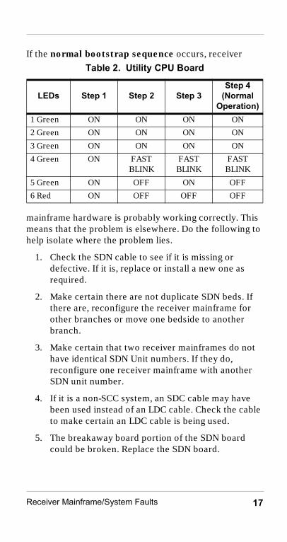
If the normal bootstrap sequence occurs, receiver
mainframe hardware is probably working correctly. This means that the problem is elsewhere. Do the following to help isolate where the problem lies.
1. Check the SDN cable to see if it is missing or defective. If it is, replace or install a new one as required.
2. Make certain there are not duplicate SDN beds. If there are, reconfigure the receiver mainframe for other branches or move one bedside to another branch.
3. Make certain that two receiver mainframes do not have identical SDN Unit numbers. If they do, reconfigure one receiver mainframe with another SDN unit number.
4. If it is a non-SCC system, an SDC cable may have been used instead of an LDC cable. Check the cable to make certain an LDC cable is being used.
5. The breakaway board portion of the SDN board could be broken. Replace the SDN board.
Table 2. Utility CPU Board
LEDs Step 1 Step 2 Step 3Step 4
(Normal Operation)
1 Green ON ON ON ON
2 Green ON ON ON ON
3 Green ON ON ON ON
4 Green ON FAST BLINK
FAST BLINK
FAST BLINK
5 Green ON OFF ON OFF
6 Red ON OFF OFF OFF
quickref.fm Page 17 Wednesday, June 5, 2002 3:08 PM

Receiver Mainframe/System Faults18
If an abnormal bootstrap sequence occurs, then the problem lies in the receiver mainframe. To troubleshoot the mainframe, do the following:
1. Remove power to the receiver mainframe and remove the 40 MHz CPC Card. Re-apply power to the receiver mainframe and observe the following LED pattern on the Utility CPU during the bootstrap routine:
2. If the sequence in the table occurs, following is the probable cause of the problem.
a. Refer to the Philips Telemetry System Compatibility Matrix Service Note to verify the compatibility between the Utility CPU and the CPC PCB.
b. The 40 MHz CPC Card was in the wrong slot. Check the correct card placement and insert the CPC Card into the correct slot. The CPC belongs in the 4th slot from the left in the rear of the mainframe. See Figure 3 on page 16.
c. The 40 MHz CPC Card is faulty. Replace it.
Table 3. Utility CPU LED Pattern without CPC Board Installed
LED Step 1 Step 2 Step 3 4 Green ON FAST BLINK FAST BLINK
5 Green ON OFF SLOW BLINK
6 Red ON OFF OFF
quickref.fm Page 18 Wednesday, June 5, 2002 3:08 PM

Receiver Mainframe/System Faults 19
3. If the sequence does not occur, do the following:
a. Remove the SDN board and re-initialize the receiver mainframe. If the sequence occurs, replace the SDN board.
b. Remove the Rack Interface board and re-initialize the receiver mainframe. If the sequence occurs, replace the Rack Interface board. If the sequence does not occur, replace the Utility CPU board. The EEPROM must be the appropriate telemetry EEPROM for the product to work properly.
c. In none of the above procedures resolves the problem, replace the Digital Backplane.
quickref.fm Page 19 Wednesday, June 5, 2002 3:08 PM

Receiver Mainframe/System Faults20
Receiver, Non-RF Problems
NO RECEIVER INOPThis INOP is generated when the telemetry system does not detect a receiver present for a configured receiver slot. This problem can occur in two ways -- in all or multiple channels or in a single channel. Depending on whether multiple or single channels are affected, the actions are different. If this INOP appears, do the following.
If the problem is in a single-channel...
1. Check and see if the receiver module for the reporting slot is seated properly. If it is not, re-seat the module.
2. The receiver mainframe may be configured for receivers that do not exist. These are empty receiver slots with SDN branch assignments. Do the following to see if this resolves the problem.
a. Check the configuration at the Central Station using the Telemetry Service Screen.
b. Using the Telemetry Service Tool, reconfigure the receiver mainframe. For any empty receiver slots, assign a “0” to the SDN Branch Number.
3. The receiver module of the reporting channel is faulty. Replace the receiver module.
4. Check to see if the rack interface to receiver backplane cable is disconnected or broken. Replace the cable if it is broken.
5. The receiver backplane is faulty. Replace the receiver backplane.
quickref.fm Page 20 Wednesday, June 5, 2002 3:08 PM

Receiver Mainframe/System Faults 21
If the problem is in multiple channels...
1. Check to see if the rack interface to the receiver backplane cable is disconnected or broken. Replace the cable if it is broken.
2. Replace the Rack Interface PCB.
3. The receiver backplane is faulty. Replace the receiver backplane.
RECEIVER MALF INOPThis INOP is generated when a receiver present for a configured slot or slots is not working. This problem can occur in two ways -- in all or multiple channels or in a single channel. If this INOP appears, do the following.
1. Check and see if the receiver module for the reporting slot is seated properly. If it is not, re-seat the module.
2. The receiver module of the reporting channel or the receiver backplane is faulty. Exchange the positions of two receiver modules (make certain they are for the same frequency range.) If the problem follows the receiver, it is faulty and must be replaced. If the problem stays with the slot, proceed to Step 3. Replace the receiver module.
3. Check to see if the rack interface to the receiver backplane cable is disconnected or broken. Replace the cable if it is broken.
4. If the receiver backplane is faulty, replace the receiver backplane.
5. If the rack interface board is bad, replace the rack interface board.
quickref.fm Page 21 Wednesday, June 5, 2002 3:08 PM
Other Problems22
Other Problems
Transmitter Button is pressed, but desired result does not occurThe transmitter button on the transmitter can be configured using the Service Tool to do the following when pressed:
• Start a recording for the patient at the Central Station when the patient presses the button, or
• Generate a system alarm (short yellow) at the Central Station when the patient presses the button, or
• Start a recording and generate an alarm at the Central Station when the patient presses the button, or
• Do nothing. The transmitter button can be disabled.
• If a transmitter is set for intermittent SpO2 measurements (manual mode, 1 minute and 5 minutes), manual measurements from the transmitter can be initiated at any time using the transmitter button. SpO2 must be turned on at the Central Station for alarms and for display and trending.
If the transmitter button is faulty, it does not generate any INOPs at the Central Station.
1. Check that the transmitter button is not turned off (disabled) at the Central Station.
2. Using the telemetry service screens available at the Central Station or the Service Tool, make certain that the transmitter button is configured in the receiver mainframe to do what is desired. If it is not, configure it appropriately.
quickref.fm Page 22 Wednesday, June 5, 2002 3:08 PM

Other Problems 23
3. Check the operation of the transmitter button using Telemetry Service Tool or Wave Viewer.
a. Make the infrared connection between the Telemetry Service Tool or Wave Viewer and the transmitter.
b. Go to the Transmitter Information Screen Two on the Telemetry Service Tool or Wave Viewer.
c. Press the transmitter button on the transmitter. Observe the Button field on the Information screen. Press and hold the transmitter button on the transmitter. After 3 to 5 seconds, the field should toggle to ON. When the button is released, it should toggle to OFF. If this does not happen, the transmitter button is not working.
Do the following if the transmitter is not working:
– Check to see if the Leads Off LEDs are working. If they are not, open the transmitter and check the ribbon cable from the case assembly to the Main PCB. Correctly connect the cable, if it not connected properly, or replace the case assembly if the cable is damaged.
– The transmitter button itself is probably broken and the Case Assembly must be replaced.
– Replace the Main PCB.
quickref.fm Page 23 Wednesday, June 5, 2002 3:08 PM

RF Troubleshooting Procedures24
RF Troubleshooting Procedures
This section deals with troubleshooting problems in the RF portion of the Telemetry System. With RF, a variety of problems can result in the same symptom and a variety of symptoms can be the result of one problem.
INVALID SIGNAL E01INOPThis INOP is a special case of interference that indicates that the receiver has locked on to a M2601A transmitter, but the ID code the transmitter is broadcasting does not match the ID code stored in the receiver mainframe. If the message appears when a battery is installed in the corresponding transmitter, the Learn Code procedure must be performed.
If the message only appears when the corresponding transmitter does not have a battery installed, there is another M2601A transmitter broadcasting nearby, at the same frequency. The frequency of one of the channels should be changed.
How does the transmitter-receiver pair recognize each other? Each transmitter sends out an ID code or “spoof code” that uniquely identifies it to a receiver module. When the receiver module receives a signal at its set frequency, and ID code matches, the receiver module accepts the signal. If the ID code does not match, the INVALID SIGNAL E01 INOP is generated.
quickref.fm Page 24 Wednesday, June 5, 2002 3:08 PM

RF Troubleshooting Procedures 25
Frequent Dropouts and NO SIGNAL, WEAK SIGNAL, and TEL CANNOT ANALYZE INOPs on a Single ChannelThese symptoms indicate that the signal being received has invalid or corrupted RF data and the signal strength is not at an acceptable level. To isolate this fault, do the following:
If the problem is occurring on a single channel:
1. If the INOP is intermittent, or if there is intermittent operation of the leads off LEDs, complete the following substeps:
a. Check to see if the battery contacts are corroded. If they are, clean or replace the battery contacts.
b. Make certain that the transmitter has both battery contact screws installed. If either screw is missing, replace it. (Screws are included in the battery contact kit).
c. Check the transmitter case screw and make certain it is not loose. If this screw is loose, the battery contacts do not make a good connection with the internal electronics. See page 1 for torque requirements.
2. The transmitter and receiver may not be set to the right frequencies.
– For systems operating between 406-480 MHz, the transmitter and receiver must be set to the same frequency.
– For extended band systems (590-632 MHz) there may be the wrong combination of transmitter frequency, frequency converter option, and receiver frequency. Check that the following is true for all installed channels:
transmitter frequency – frequency converter option
= receiver frequency
quickref.fm Page 25 Wednesday, June 5, 2002 3:08 PM

RF Troubleshooting Procedures26
3. If the frequencies are set properly, use the Telemetry Service Tool or Wave Viewer to check the transmitter information. Refer to NO SIGNAL INOP and an RF OUT OF LOCK INOP at Telemetry Service Tool or Wave Viewer.
4. Make certain that the patient is in the antenna coverage area.
5. Check if the leadset is attached (the leadset is the broadcast antenna). Leadset wires must be shielded. The RF connection is made only to the shields.
6. The transmitter is not transmitting a signal. This can be a result of a dead battery or a power supply failure within the transmitter. To determine if this is the problem, remove one of the leads from the patient and see if the corresponding Leads Off LED illuminates. If it does, proceed to Step 7. If it does not, do the following:
a. Make certain that the battery is installed properly.b. Replace the battery with a fresh one.c. If an ECG and SpO2 capable transmitter is being
used (even if SpO2 is not being monitored) make certain that a lithium or alkaline battery is being used). A zinc-air battery cannot be used with an ECG and SpO2 capable transmitter. To check if the SpO2 option is installed in the transmitter, look in the battery compartment. The option string “1SP” indicates that the SpO2 option is installed.
d. Open the transmitter and make sure that the RF Cable is connected to the Front End Assembly and to the Main PCB. If not, connect it properly using the RF Cable seating tool following the procedures for installing the RF Cable in Chapter 6 of the Service and Reference Guide.
e. Replace the Main PCB in the transmitter.
quickref.fm Page 26 Wednesday, June 5, 2002 3:08 PM

RF Troubleshooting Procedures 27
7. The next step is to identify where the problem lies in the system. This can be done by changing the frequencies in both transmitters and receivers, to isolate a fault in a single channel, given there is at least one other good channel. The possibilities are:
– faulty transmitter– faulty receiver– bad frequency
The following procedure determines the method for using changing frequencies to isolate problems.
Given: 1. One known bad channel, consisting of:
– Frequency 1– Transmitter A– Receiver A
2. One known good channel, consisting of:– Frequency 2– Transmitter B– Receiver B
Isolate:
The fault to Frequency 1, Transmitter A, or Receiver A.
This procedure requires using the Telemetry Service Tool or Wave Viewer to change transmitter frequencies, and the Central Station to change receiver frequencies. The Telemetry Service Tool can be used to change both the transmitter frequencies (trtool) and the receiver frequencies (mftool).
Step 1. Change the transmitter frequency of Transmitter A to the frequency of the known good channel (Frequency 2). Change the transmitter frequency of Transmitter B to the frequency of the bad channel (Frequency 1). Observe what happens:
a. If the problem remains with Transmitter A, Transmitter A is faulty and should be repaired.
quickref.fm Page 27 Wednesday, June 5, 2002 3:08 PM

RF Troubleshooting Procedures28
b. If the problem moves to Transmitter B, the problem is not in Transmitter A (transmitter of the original bad channel). Proceed to Step 2.
Step 2. Because the problem is not in Transmitter A, either Receiver A or the frequency itself is faulty. To isolate between the two, first change the receiver frequency of Receiver A to the frequency of the known good channel (Frequency 2). Change the receiver frequency of Receiver B to the frequency of the bad channel (Frequency 1). Observe what happens:
a. If the problem remains with Frequency 1, the problem is in the frequency. The problem must be further isolated to determine whether it is in the antenna system or the RF Signal environment. Either an Antenna System Troubleshooting procedure or an RF History Strip evaluation must be performed.
b. If the problem moves to Frequency 2, the fault is in Receiver A. Before replacing the receiver, check the following:.
— Make certain that the semi-rigid cable is connected correctly and not damaged. If the cable is suspected, swap it with one of the other cables in the mainframe and see if the problem switches to the other channel. If it does, replace the cable.
— If the semi-rigid cable is OK, then the receiver module is probably bad. Exchange the receiver module with another one to confirm.
— If the problem follows the receiver, replace the receiver PCB.
— If the problem remains with the slot, replace the antenna distribution board in the receiver mainframe.
quickref.fm Page 28 Wednesday, June 5, 2002 3:08 PM
RF Troubleshooting Procedures 29
Frequent Dropouts and NO SIGNAL, WEAK SIGNAL, and TEL CANNOT ANALYZE INOPs with Multiple Channels
1. For extended band systems - See Step 2 of the previous INOP for a Single Channel
2. Check that the antenna system has power - Antenna/Combiners, amplifiers, power tees, frequency converters, and filters should all have their LEDs lit. If they do not:
a. Check to see if a power tee circuit breaker has tripped due to a short in the system by resetting the circuit breaker
b. If the system has failed while testing the hospital’s emergency power, check that all power modules are plugged into emergency power outlets.
3. Check that the patients are in the antenna system coverage area.
4. Check for hardware failures or installation problems with the antenna system and receiver mainframe.
NoteThe antenna system used with a telemetry system operating in the extended band must be an M2613/14/15A or an M1413/14/15A/B antenna system that has been upgraded for operation in the extended band, otherwise the signal will be attenuated below an acceptable level. Upgrades typically consist of replacing the non-extended band antenna components (M14XXX series) with extended band compatible antenna components (M26XXX series).
quickref.fm Page 29 Wednesday, June 5, 2002 3:08 PM

RF Troubleshooting Procedures30
5. The signal from the patient may be subject to shadowing. Shadowing is caused by RF blocking sources between the patient and the antenna system. If the symptom is frequent NO SIGNAL or WEAK SIGNAL INOPs on a specific channel when the patient is in a particular room, the problem is probably caused by shadowing. Check for RF blocking sources in the patient’s area and, if possible, have them moved. If the blocking sources cannot be moved, the antenna will have to be repositioned. Contact a Philips Medical Systems service representative for assistance.
6. The antenna system may be inadequate. Contact a Philips Medical Systems service representative for assistance.
Frequent Dropouts along with TEL CANNOT ANALYZE and INTERFERENCE INOPs
1. Print the RF History Strip for the problem channel and check for interference problems.
2. Interference due to Heterodyning
– Interfering signals can be generated if transmitters are stored with the batteries installed and are in close proximity to other transmitters, for example in a drawer. The signal broadcasts into another transmitter where it mixes or heterodynes in the circuitry creating other frequencies that are then rebroadcast, interfering with other operating transmitters.
– M2601A transmitters can be configured for RF auto-shutoff after 10 minutes from a leads off situation.
– Take the batteries out of all non-M2601A transmitters when they are not in use, and all M2601A transmitters that have the RF auto-shutoff feature configured NO.
quickref.fm Page 30 Wednesday, June 5, 2002 3:08 PM

RF Troubleshooting Procedures 31
3. Remove the battery from the problem transmitter and monitor the RF History Strip for that channel.
a. On-Channel or Narrowband Interference - is defined as an interference source that occupies the same bandwidth as the transmitter and only interferes with one channel or two frequency adjacent channels.
It is likely that the channel is set to the same frequency as another telemetry unit. To correct this, change to a clear frequency or remove the interference source. Be certain and check for M2600A Telemetry Channels, M1403A Digital Telemetry channels, 78100/101A Analog Telemetry channels, and for M1310A and 80240A Fetal Telemetry channels. Also check for other radio devices, such as walkie-talkies, paging systems, ambulance systems, etc.
b. Broadband Noise - a broadband interference source occupies the bandwidth of many channels causing degradation of the carrier-to-noise ratio (CNR) on all of the telemetry channels for as long as it is present. This results in an increase in dropouts and TEL CANNOT ANALYZE”/”INTERFERENCE INOPs on all of the channels. The system has quiet and noisy periods. When the noise source is on, the system is noisy. When the source is off, the system performs well. To eliminate the problem, do the following:
– Troubleshoot the problem as it is occurring. Use the RF History Strips and information from users to determine if there is a pattern, when the episodes occur, and how long they last. If there is a pattern, (e.g. every morning between 6 and 8am, the first weekend of the month etc.) try to predict when the next occurrence will happen and prepare to troubleshoot.
quickref.fm Page 31 Wednesday, June 5, 2002 3:08 PM

RF Troubleshooting Procedures32
– Locate where the signal is entering the system. This can be done by removing branches from the antenna system to see when the system quiets down. Remember that patients being received by antennas that have been removed cannot be monitored.
– Remember! Sources can move, which makes troubleshooting a bit more difficult, so work quickly.
– Fix the system by eliminating or repairing the source. Relocate or permanently remove the antenna where the signal is entering. Some things to check are:
— failing fluorescent light ballast
— vacuum cleaners
— hand drills
— electric pencil sharpeners
— nurse call systems
— vacuum tube delivery system motors
— unused, unterminated, but still powered antenna systems
— anything with a motor is suspect. Dirty motor brushes can arc and cause broadband noise.
quickref.fm Page 32 Wednesday, June 5, 2002 3:08 PM
RF Troubleshooting Tools 33
RF Troubleshooting Tools
Refer to the Philips Telemetry System Service and Reference Guide.
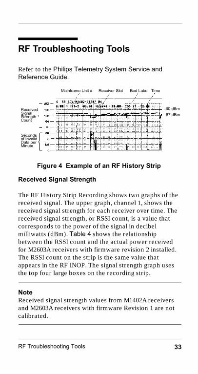
Figure 4 Example of an RF History Strip
Received Signal Strength
The RF History Strip Recording shows two graphs of the received signal. The upper graph, channel 1, shows the received signal strength for each receiver over time. The received signal strength, or RSSI count, is a value that corresponds to the power of the signal in decibel milliwatts (dBm). Table 4 shows the relationship between the RSSI count and the actual power received for M2603A receivers with firmware revision 2 installed. The RSSI count on the strip is the same value that appears in the RF INOP. The signal strength graph uses the top four large boxes on the recording strip.
NoteReceived signal strength values from M1402A receivers and M2603A receivers with firmware Revision 1 are not calibrated.
Mainframe Unit # Receiver Slot
ReceivedSignalStrengthCount
Seconds of InvalidData perMinute
-60 dBm-87 dBm
TimeBed Label
quickref.fm Page 33 Wednesday, June 5, 2002 3:08 PM

RF Troubleshooting Tools34
NoteApproximate gain conversion from decibels (dB) to RSSI counts is 1dB � 2.4 counts.
Table 4. RSSI Count and Corresponding Power Level
RSSI Count M2603A FW Rev 2Power in dBm
255 (top major division on strip)
greater than -40
243 -40230 -47218 -51205 -55192
(next major division on strip)-60
179 -68166 -74154 -79141 -83128
(next major division on strip)-87
115 -94102 -9890 -10177 less than -10464
(next major division on strip)less than -104
51 less than -10438 less than -10426 less than -10413 less than -1040
(lowest major division in upper graph)less than -104
quickref.fm Page 34 Wednesday, June 5, 2002 3:08 PM

RF Troubleshooting Tools 35
Invalid Data
The lower graph, channel 2, of Figure 4, shows the number of invalid data packets received. Note that the invalid data is graphed logarithmically.
Invalid data packets are graphed as a function of time. The graph shows the amount of invalid data packets (shown by the amplitude or height of the spike) and the duration of time the invalid packets are received (shown by the pulse width of the spike). The invalid packets are graphed using the bottom 3 boxes on the strip recording, and are measured in seconds of invalid data per minute of monitoring.
Any spikes that remain in the bottom box indicate a low percentage of invalid data packets received and indicates good performance for a receiver. As the amplitude of the spikes increase, the higher percentage of invalid data packets have been received. Spikes that reach the top of the third box, indicate an entire minute's worth of invalid data packets received.
Expected Performance
• Mean Signal Strength of about -60 dBm (192 counts) is expected
• Dropouts are likely to occur if the signal strength drops below -87 dBm (128 counts)
• Signal strength “fades” of 30 dB are expected.
• Good noise floor measurement would be about -100 dBm (90 counts)
quickref.fm Page 35 Wednesday, June 5, 2002 3:08 PM

RF Troubleshooting Tools36
Figure 5 Boundaries of Good and Bad Data
RF History Strip - helpful hints:
• A 92% reduction on a copier will allow 24- hours of one channel to fit on an 8.5” x 11” sheet of paper.
• Draw lines at the -60dBm (“good”) and the -87dBm (“bad”) power levels on the RSSI plot.
• Examine the RF history strip, and any other recording strips or wave review printouts and look for the fol-lowing:
– Is the signal strength where it is expected?
– Does the time and number of “invalids” on the RF history strip correlate with any available ECG recording strips or wave review printouts?
– What is the signal strength when “invalids” occur? Does this indicate corruption due to a low-signal strength or due to interference?
– Are there specific channels exhibiting problems, or are there patterns across channels?
-60 dBm-87 dBm104 dBm
-40 dBmGood
Bad
quickref.fm Page 36 Wednesday, June 5, 2002 3:08 PM

RF Troubleshooting Tools 37
Aligned Notation
The RF History Strip Recording contains the following aligned notation:
1. Date can be found on the strip after the 24:00 time stamp.
2. Time stamp is given every 2 hours.The hour starts at the colon (:) in the time stamp. Each small box is 5 minutes. Twelve small boxes equals 1 hour.
3. SDN Unit number of the recorded receiver mainframe.
4. Receiver number (Rcvr) which is the receiver slot being recorded for the respective receiver mainframe.
5. Bed label for the receiver slot. This is the bed label assigned at the central station to the receiver slot.
6. Marker between receivers: the end of the RF History Strip for one receiver and the start of the strip for the next receiver is indicated by a short marker.
This information is listed at the top of the received signal strength graph for the receiver module in the Receiver Mainframe being printed. The information above the grid lines can either be the mainframe revision or the status log, depending on which screen was active when the RF History strip was requested.
quickref.fm Page 37 Wednesday, June 5, 2002 3:08 PM
Part Lists38
Part Lists
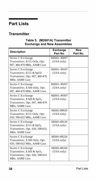
TransmitterTable 5. (M2601A) Transmitter Exchange and New Assemblies
Description Exchange Part No.
New Part No.
Series C Exchange Transmitter, ECG Only, Opt. 007, 460-470 MHz, AAMI Case
M2601- 89007(USA only)
Series C Exchange Transmitter, ECG & SpO2 Transmitter, Opt. 007, 460-470 MHz, AAMI Case
M2601- 89107(USA only)
Series C Exchange Transmitter, EASI Only, Opt. 007, 460-470 MHz, AAMI Case
M2601- 89207(USA only)
Series C Exchange Transmitter, EASI & SpO2 Transmitter, Opt. 007, 460-470 MHz, AAMI Case
M2601- 89307(USA only)
Series C Exchange Transmitter, ECG Only, Opt. 020, 590-632 MHz, AAMI Case
M2601-89020(USA only)
Series C Exchange Transmitter, ECG & SpO2 Transmitter, Opt. 020, 590-632 MHz, AAMI Case
M2601-89120(USA only)
Series C Exchange Transmitter, EASI Only, Opt. 020, 590-632 MHz, AAMI Case
M2601-89220(USA only)
Series C Exchange Transmitter, EASI & SpO2 Transmitter, Opt. 020, 590-632 MHz, AAMI Case
M2601-89320(USA only)
quickref.fm Page 38 Wednesday, June 5, 2002 3:08 PM

Part Lists 39
Series B Exchange Transmitter, ECG Only, Opt. 007, 460-470 MHz, AAMI Case
M2601-88007(USA only)
Series B Exchange Transmitter (ECG/SpO2), Opt. 007, 460-470 MHz, AAMI case
M2601-88107(USA only)
Series B Exchange Transmitter, ECG Only, Opt. 020, 590-632 MHz, AAMI Case
M2601-88020(USA only)
Series B Exchange Transmitter, ECG & SpO2 Transmitter, Opt. 020, 590-632 MHz, AAMI Case
M2601-88120(USA only)
Battery Door M2601-40029
Battery Contact Kit - for use with the Battery Extender – includes screws and Battery Door
M2601-60174
Battery Extender Cradle M2601-60014
Battery Extender Power Module - USA - 120V, 60Hz
M2601-60018
Battery Extender Power Module - Euro - 220-240 V, 50 Hz
M2601-60183
Battery Extender Power Module - Japan - 100 V, 50/60 Hz
M2601-60184
Battery Extender Power Module - UK - 220-240 V, 50 Hz
M2601-60185
Battery Extender Power Module - Australia - 220-240 V, 50 Hz
M2601-60186
Table 5. (M2601A) Transmitter Exchange and New Assemblies
Description Exchange Part No.
New Part No.
quickref.fm Page 39 Wednesday, June 5, 2002 3:08 PM

Part Lists40
Single Use Screw Kit (all countries except Japan)
M2601-68302
Single Use Screw Kit (Japan only)
M2601-68304
Series C EASI Case Assembly, AAMI Colors (green, black, red, white and brown) without FCC ID number embossed
M2601-60171
Series C EASI Case Assembly, IEC Colors (black, yellow, green, red and white) without FCC ID number embossed
M2601-60172
Series C Standard ECG Case Assembly, AAMI Colors (green, black, red, white and brown) without FCC ID number embossed
M2601-60025
Series C Standard ECG Case Assembly, IEC Colors (black, yellow, green, red and white) without FCC ID number embossed
M2601-60026
Series B Standard ECG Case Assembly, AAMI Colors (green, black, red, white and brown, without FCC ID number embossed)
M2601-60407
Series B Standard ECG Case Assembly, IEC Colors (black, yellow, green, red and white, without FCC ID number embossed)
M2601-60408
RF Grounding Strip (applied to case assembly)
M2601-83033
Table 5. (M2601A) Transmitter Exchange and New Assemblies
Description Exchange Part No.
New Part No.
quickref.fm Page 40 Wednesday, June 5, 2002 3:08 PM

Part Lists 41
4 mW Main PCB, Opt. 001, 406-412.5 MHz
M2601-68101 M2601-60101
4 mW Main PCB, Opt. 002, 412.5-421.5 MHz
M2601-68102 M2601-60102
4 mW Main PCB, Opt. 003, 421.5-430 MHz
M2601-68103 M2601-60103
4 mW Main PCB, Opt. 004, 430-440 MHz
M2601-68104 M2601-60104
4 mW Main PCB, Opt. 005, 440-450 MHz
M2601-68105 M2601-60105
4 mW Main PCB, Opt. 006, 450-460 MHz
M2601-68106 M2601-60106
4 mW Main PCB, Opt. 007, 460-470 MHz
M2601-68107 M2601-60107
4 mW Main PCB, Opt. 008, 470-480 MHz
M2601-68108 M2601-60108
4 mw Main PCB, Opt. 020, 590-614 MHz
M2601-68120 M2601-60120
1 mW Main PCB, Opt. 002, 412.5-421.5 MHz (Japan)
M2601-68502 M2601-60502
1 mW Main PCB, Opt. 003, 421.5-430 MHz (Japan)
M2601-68503 M2601-60503
1 mW Main PCB, Opt. 005, 440-450 MHz (Japan)
M2601-68505 M2601-60505
ECG PCB M2601-60300
SpO2 Board M2601-68010 M2601-66010
Blank PCB M2601-40024
Front End Assembly M2601-60200
SpO2 Connector Plug (ECG-only transmitters)
M2601-40013
Combiner Hood M2601-40014
Table 5. (M2601A) Transmitter Exchange and New Assemblies
Description Exchange Part No.
New Part No.
quickref.fm Page 41 Wednesday, June 5, 2002 3:08 PM

Part Lists42
Combiner Latch M2601-40019
RF Cable 8120-6790
Main Cage Brace (with labels attached)
M2601-00607
Grounding Clip (main cage brace)
M2601-20021
Transmitter Channel ID Labels (1-100)
M2601-83026
Blank Serial Number Label M2601-83021
“Philips Series B” & “Series C” Identification Label
M2601-83061
PTT Labels (international except France, Canada, Italy, Brazil)
M2601-83300
PTT Label - France M2601-83202
PTT Label - Canada, Italy, Brazil
M2601-83321
FCC Label – Option 007 5969-3925
FCC Label – Option 020 (extended UHF band)
5969-3926
Extended UHF Band Upgrade (007 to 020) FCC Label
M2601-83056
Supplies and Accessories for Transmitter
Telemetry leadset - 3 wire snap, 30" (76 cm), AAMI colors
M2590A
Telemetry leadset - 3 wire grabber, 30" (76 cm), AAMI colors
M2591A
Telemetry leadset - 5wire snap, 30" (76 cm), AAMI colors
M2592A
Table 5. (M2601A) Transmitter Exchange and New Assemblies
Description Exchange Part No.
New Part No.
quickref.fm Page 42 Wednesday, June 5, 2002 3:08 PM

Part Lists 43
Telemetry leadset - 5 wire grabber, 30" (76 cm), AAMI colors
M2593A
Telemetry leadset - 3 wire snap, 30" (76 cm), IEC colors
M2594A
Telemetry leadset - 3 wire grabber, 30" (76 cm), IEC colors
M2595A
Telemetry leadset - 5wire snap, 30" (76 cm), IEC colors
M2596A
Telemetry leadset - 5 wire grabber, 30" (76 cm), IEC colors
M2597A
Telemetry 3-wire leadset combiner
M2598A
Telemetry 5-wire leadset combiner
M2599A
Philips Reusable Adult Finger SpO2 Transducer
M1191A
Philips Reusable Pediatric/Small Adult Finger SpO2 Transducer
M1192A
Philips Reusable Adult/Pediatric Ear Clip SpO2 Transducer
M1194A
Wristband for SpO2 finger transducers
M1627A
Adapter Cable for Nellcor Oxisensor � Disposable SpO2 Transducers
M1943A
Nellcor Oxisensor � D-25, SpO2 Transducer
M1904B
Table 5. (M2601A) Transmitter Exchange and New Assemblies
Description Exchange Part No.
New Part No.
quickref.fm Page 43 Wednesday, June 5, 2002 3:08 PM

Part Lists44
Nellcor Oxisensor � D-20, SpO2 Transducer
M1903B
Disposable Telemetry Transmitter Pouch, box of 50
9300-0768-050
Disposable Telemetry Transmitter Pouch, box of 200
9300-0768-200
9V Lithium Batteries, Box of 10
ULBU9VLJ
8.4V Zinc Air Batteries, Box of 12
40455A
Tools for Transmitter
Battery Contact Screw Holding Tool
M2601-67001
Torque Screwdriver 1535-2653
RF Cable Tool M2601-67002
Special bit for Main Case Screw (Japan Only)
5966-5066
Transmitter Testbox M2600-67000
RG-6U Antenna Cable, Non-Plenum, 1 ft or 0.3 meters (for use with testbox)
M1413-60100
Telemetry Service Tool Software (transmitter tool revision B.00.05, mainframe tool revision B.00.05, frequency calculator revision A.00.00)
M2600-67013
Serial-to-Infrared Converter II M2601-63020
Serial-to-Infrared Converter M2601-63010
Revision B.00.05 Transmitter Main PCB Firmware Floppy Disk (Release C)
M2601-50006
Table 5. (M2601A) Transmitter Exchange and New Assemblies
Description Exchange Part No.
New Part No.
quickref.fm Page 44 Wednesday, June 5, 2002 3:08 PM

Part Lists 45
Receiver Module
Revision A.03.02 Transmitter Main PCB Firmware Floppy Disk (Release B)
M2601-50005
Revision A.02.42 SpO2 PCB Firmware floppy disc
M2601-10030
Table 6. Receiver Module Exchange and New Assemblies
Description Exchange Part No.
New Part No.
Semi-Rigid Cable Assembly M1402-60690
Small RF Gasket M2603-01000
Medium RF Gasket M2603-01001
Large RF Gasket M2603-01002
Receiver Shield Assembly M2603-60540
Receiver Board Opt. 001 406-412.5 MHz
M2603-68010 M2603-60010
Receiver Board Opt. 002 412.5-421.5 MHz
M2603-68020 M2603-60020
Receiver Board Opt. 003 421.5-430 MHz
M2603-68030 M2603-60030
Receiver Board Opt. 004 430-440 MHz
M2603-68040 M2603-60040
Receiver Board Opt. 005 440-450 MHz
M2603-68050 M2603-60050
Receiver Board Opt. 006 450-460 MHz
M2603-68060 M2603-60060
Table 5. (M2601A) Transmitter Exchange and New Assemblies
Description Exchange Part No.
New Part No.
quickref.fm Page 45 Wednesday, June 5, 2002 3:08 PM

Part Lists46
Receiver Board Opt. 007 460-470 MHz
M2603-68070 M2603-60070
Receiver Board Opt. 008 470-480 MHz
M2603-68080 M2603-60080
Screw, (short, receiver shield) 0515-2735
Screw, receiver shield to PCB shield (5)
0515-1280
Screw, receiver to mainframe 0515-0842
Washer (for RF connector) 2190-0124
Nut (for RF connector) 2950-0078
M2603A Receiver FW Rev. A.00.02
M2603-84100
Receiver Channel ID Labels (1-100)
M2603-83018
M1402A Receiver FW 5 (for use with M2601A - Transmitters) Note: The following chip is used in upgrades of M1403A Systems to Philips Telemetry Functionality
M2603-84010
Tools
Chip Extraction Tool (44PPLCC)
8710-1995
Table 6. Receiver Module Exchange and New Assemblies
Description Exchange Part No.
New Part No.
quickref.fm Page 46 Wednesday, June 5, 2002 3:08 PM

Part Lists 47
Receiver MainframeTable 7. Receiver Mainframe
Exchange and New Assemblies
Description Exchange Part No.
New Part No.
Fan 3160-0816
Rack Interface Board M1088-68501 M1088-66501
SDN Interface Board M1082-68502 M1082-66502
Air Filter M1401-02100
Receiver Backplane M1401-60300
Digital Backplane M1401-60400
Chassis Assembly (includes Top Cover)
M2604-00100
Transformer Cover M2604-00220
Blank Board Cover (Large) M2604-00300
Blank Board Cover (small) M2604-00290
Rack Interface PCB Bracket M2604-00400
Card Guide M2604-40000
Power Supply M2604-68005 M2604-60005
Utility CPU PCB (Note: Return without EEPROM)
M1059-68501 M1059-66501
Telemetry EEPROM Rev E M2604-84003
Telemetry EEPROM Rev. D M2604-84002
CPC Board Assembly M2604-68010 M2604-60010
Antenna Distribution Assembly M2604-68620 M2604-60620
Antenna Distribution PC Board M2604-68648 M2604-60648
Malfunction LED Cable Assembly
M2604-60740
Front Dress Cover M2604-81000
Antenna Cable Assembly M1401-60750
Top Cover Assembly M2604-00240
RF Cable (part of receiver module)
M1402-60690
quickref.fm Page 47 Wednesday, June 5, 2002 3:08 PM

Part Lists48
Perm IEC Ground Cable M1401-60675
Lamp Clip Set 1400-0560
Grommet 0400-0133
RFI Spring 5001-1320
Cable, Receiver Backplane to Antenna Distribution PCB
M1401-60770
Cable, Rack Interface to Receiver Backplane
M1401-60650
Power Supply Cable to Digital Backplane
M1401-60670
Power Supply Cable to Receiver Backplane
M1401-60660
78000AI-#R86 Mount Retrofit Kit
78000-91907
Mount Assembly (R86 Mount) M1401-02970
Unit Mount (R86 Mount) M1401-02990
Power Cord, U.S.A. 8120-5429
Power Cord, U.K. 8120-1351
Power Cord, Australia/New Zealand
8120-4475
Power Cord, Europe 8120-1689
Power Cord, Switzerland 8120-2104
Power Cord, Denmark 8120-2956
Power Cord, S. Africa/India 8120-4211
Power Cord, China 8120-8376
Fuse - 1.6A, 250V (earlier PS) 2110-1001
Fuse - 0.8A, 250V(earlier PS) 2110-1002
Machine Screw (for Receivers, Digital Cards, and Power Supply)
0515-0842
Table 7. Receiver Mainframe Exchange and New Assemblies
Description Exchange Part No.
New Part No.
quickref.fm Page 48 Wednesday, June 5, 2002 3:08 PM

Part Lists 49
Screw M3 x 0.5 (for backplane assemblies)
0515-0897
Screw M3 x 6mm (Analog Output PCB, CPC PCB, and Antenna Distribution PCB)
0515-1146
Screw M5 x 10mm pan (R86 mount)
0515-1546
Additional Parts for European VersionTiger Strips
Qty 1, 16” (40.6 cm) 5969-3994
Qty 2, 2.75” (7.0 cm) 5969-3995
Qty 2, 7” (17.9 cm) 5969-3996
Rear RF Brace (B) M2604-60801
Tools EEPROM Chip Extraction Tool M1186-45001
CPC Programming Tool M2300-67100
Telemetry Receiver Mainframe Software Flash Card Revision E.00.19 (Release C)
M2604-70007
Telemetry Receiver Mainframe Software FLASH card, Revision D.03.02 (Release B)
M2604-70006
Telemetry Service Tool Software - transmitter tool rev. B.00.01 - mainframe tool rev. B.00.01 - frequency calculator rev. A.00.00
M2600-67013
Telemetry Configuration Tool M2601-67020
RS-232 PCB M1085-66501
RS-232 Cable HP 24542G
Safety Analyzer
Table 7. Receiver Mainframe Exchange and New Assemblies
Description Exchange Part No.
New Part No.
quickref.fm Page 49 Wednesday, June 5, 2002 3:08 PM

Part Lists50
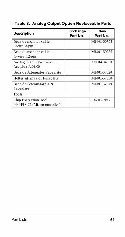
Analog Output Option Replaceable PartsTable 8. Analog Output Option Replaceable Parts
Description Exchange Part No.
New Part No.
Analog output board assembly M2604-68021 M2604-60021
Analog link cable M1401-60751
Analog trunk cable M1401-60752
Output connector box assembly
M2604-60961
Output connector box power module
M2600-60008
Power Module Mount M1407-00070
Power Module Mount “L” Bracket
M1407-00040
Analog output cable, non-plenum, 15.2 m or 50ft.
M1401-60761
Analog output cable, non-plenum, 30.5 m or 100ft.
M1401-60762
Analog output cable, non-plenum, 76.2 m or 250ft.
M1401-60763
Analog output cable, non-plenum, 152.4 m or 500ft.
M1401-60764
Analog output cable, plenum, 15.2 m or 50ft.
M1401-60765
Analog output cable, plenum, 30.5 m or 100ft.
M1401-60766
Analog output cable, plenum, 76.2 m or 250ft.
M1401-60767
Analog output cable, plenum, 152.4 m or 500ft.
M1401-60768
Bedside monitor cable, 3-wire, 8-pin
M1401-60753
Bedside monitor cable, 3-wire, 12-pin
M1401-60754
quickref.fm Page 50 Wednesday, June 5, 2002 3:08 PM
Part Lists 51
Bedside monitor cable, 5-wire, 8-pin
M1401-60755
Bedside monitor cable, 5-wire, 12-pin
M1401-60756
Analog Output Firmware — Revision A.01.00
M2604-84050
Bedside Attenuator Faceplate M1401-67020
Holter Attenuator Faceplate M1401-67030
Bedside Attenuator/SDN Faceplate
M1401-67040
Tools
Chip Extraction Tool (44PPLCC) (Microcontroller)
8710-1995
Table 8. Analog Output Option Replaceable Parts
Description Exchange Part No.
New Part No.
quickref.fm Page 51 Wednesday, June 5, 2002 3:08 PM

Part Lists52
M1413/14/15B Antenna System PartsTable 9. (M1408A) Active Antenna/Combiner
Replaceable Parts
Description New Part No.Base, Active Antenna/Combiner (Philips M1408A)
M1408-60004
Wall Mount M1404-60001
Flexible antenna - 406 to 450 MHz 0950-2029
Flexible antenna - 450 to 512 MHz 0950-2028
Table 10. (M1406A)Line Amplifier Replaceable Parts
Description New Part No.Line amplifier M1406-67000
Mounting Bracket M1406-00060
Table 11. (M1407A) Multiple Unit Power Supply Replaceable Parts
Description New Part No.Power Tee M1407-67000
Mounting bracket M1407-00060
Power module - 100-240 VAC M2600-60008
Power Module Mount “L” Bracket M1407-00040
Power Module Mounting Bracket M1407-00070
Table 12. M1413/14/15B Antenna System Parts
Description New Part No.4-way Spiliter/Combiner 0960-0324
2-way Splitter/Combiner 0960-0323
Spacer 2-way M1415-00003
Spacer 4-way M1415-00004
quickref.fm Page 52 Wednesday, June 5, 2002 3:08 PM

Part Lists 53
DC blocking capacitor Hewlett-Packard 10240B
75-ohm terminator with DC block 1250-2403
BNC (m) to BNC (m) adapter 1250-0216
RG-6U Antenna cable (non-plenum, 0.3 m or 1ft)
M1413-60100
RG-6U Antenna cable (non-plenum, 1.5 m or 5ft)
M1413-60105
RG-6U Antenna cable (non-plenum, 3.0 m or 10ft)
M1413-60101
RG-6U Antenna cable (non-plenum, 18.9 m or 62ft)
M1413-60103
RG-6U Antenna cable (non-plenum, 42.4 m or 139ft)
M1413-60102
RG-6U Antenna cable, special(non-plenum, specified to order)
M1413-60109M2617A-#J30
RG-11U Antenna cable, special(non-plenum, specified to order)
M1413-60119M2617A-#J31
RG-6U Antenna Cable, plenum, 18.9 m.or 62ft.
M1414-60103
RG-6U Antenna Cable, plenum, 42.4 m.or 139ft.
M1414-60102
RG-6U Antenna Cable, Special plenum, specify to order
M1414-60109M2617A-#J40
RG-11U Antenna Cable, Special plenum, specify to order
M1414-60119M2617A-#J41
Tools
Transmitter Testbox M2600-67000
RG-6U Antenna Cablenon-plenum, 0.3 m or 1ft. (for use with testbox)
M1413-60100
Table 12. M1413/14/15B Antenna System Parts
Description New Part No.
quickref.fm Page 53 Wednesday, June 5, 2002 3:08 PM

Part Lists54
M2613/14/15A Antenna System PartsTable 13. M2613/14/15A Antenna System Parts
Description Exchange Part No. New Part No.
Base, Antenna/Combiner M2608-60000
Antenna Wall Mount M1404-60001
Black Flexible Antenna, 406-650MHz
5969-3927
White Flexible Antenna, 406-650MHz
5969-3924
Line Amplifier M2606-60000
Power Tee M2607-60000
Power Module, CE Marked M2600-60008
Power Module (0950-3221) Mount “L” Bracket
M1407-00040
Mounting Bracket for Power Module, 0950-3221
M1407-00070
Power Cord, U.S.A. 8120-5429
Power Cord, U.K. 8120-1351
Power Cord, Australia/New Zealand
8120-4475
Power Cord, Europe 8120-1689
Power Cord, Switzerland 8120-2104
Power Cord, Denmark 8120-2956
Power Cord, S. Africa/India 8120-4211
Power Cord, China 8120-8376
2-Way Splitter/Combiner 0960-0323
Spacer, 2-Way M1415-00003
4-Way Splitter/Combiner 0960-0324
Spacer, 4-Way M1415-00004
Attenuator, 1dB 0955-1085
Attenuator, 2dB 0955-1086
Attenuator, 3dB 0955-1087
Attenuator, 4dB 0955-1088
quickref.fm Page 54 Wednesday, June 5, 2002 3:08 PM

Part Lists 55
Attenuator, 5dB 0955-1089
Attenuator, 6dB 0955-1090
Attenuator, 7dB 0955-1091
Attenuator, 8dB 0955-1092
Attenuator, 9dB 0955-1093
Filter, 430-440 MHz M2612-60004
Filter, 440-450 MHz M2612-60005
Filter, 450-460 MHz M2612-60006
Filter, 460-470 MHz M2612-60007
Filter, 590-596 MHz M2612-60034
Filter, 596-602 MHz M2612-60035
Filter, 602-608 MHz M2612-60036
Filter, 608-614 MHz M2612-60037
Filter, 614-620 MHz M2612-60038
Filter, 620-626 MHz M2612-60039
Filter, 626-632 MHz M2612-60040
DC Blocking Capacitor HP 10240B
75 ohm Terminator with DC Block
1250-2403
BNC (m) to BNC (m) adapter 1250-0216
RG-6U Antenna Cable, non-plenum, 0.3 m or 1ft.
M1413-60100
RG-6U Antenna Cable, non-plenum, 1.5 m or 5ft.
M1413-60105
RG-6U Antenna Cable, non-plenum, 3.0 m or 10ft.
M1413-60101
RG-6U Antenna Cable, Intermediate,non-plenum, 18.9 m or 62ft.
M1413-60103
RG-6U Antenna Cable, Mainnon-plenum, 42.4 m or 139ft.
M1413-60102
Table 13. M2613/14/15A Antenna System Parts
Description Exchange Part No. New Part No.
quickref.fm Page 55 Wednesday, June 5, 2002 3:08 PM

Part Lists56
RG-11 Antenna Cable, non-plenum, 34.1 m or 112ft. intermediate cable
M1413-60203
RG-11 Antenna Cable, non-plenum, 76.2 m or 250ft main cable
M1413-60202
RG-6U Antenna Cable, non-plenum, Special Order, Specify Loss in dB
M2617A-#J30(M1413-60109)
RG-11U Antenna Cable, non-plenum, Special Order, Specify Loss in dB
M2617A-#J31(M1413-60119)
RG-6U Antenna Cable, plenum, 18.9 m or 62ft.
M1414-60103
RG-6U Antenna Cable,plenum, 42.4 m or 139ft.
M1414-60102
RG-11 Antenna Cable, Intermediate, plenum, 22.9 m or 75ft.
M1414-60203
RG-11 Antenna Cable, Main, plenum, 50.3 m or 165ft.
M1414-60202
RG-6U Antenna Cable,plenum, Special Order, specify Loss in dB
M2617A-#J40(M1414-60109)
RG-11U Antenna Cable, plenum, Special Order, specify Loss in dB
M2617A-#J41(M1414-60119)
ToolsTransmitter Testbox M2600-67000
RG-6U Antenna Cable, non-plenum, 0.3 m or 1ft. (for use with testbox)
M1413-60100
9dB Attenuator 0955-1093
Table 13. M2613/14/15A Antenna System Parts
Description Exchange Part No. New Part No.
quickref.fm Page 56 Wednesday, June 5, 2002 3:08 PM

Part Lists 57
M2616A Frequency ConverterTable 14. M2616A Frequency Converter Parts
Description Exchange Part No.
New Part No.
External Frequency Converter Assembly, Option 130
M2616-68130 M2616-60130
External Frequency Converter Assembly, Option 136
M2616-68136 M2616-60136
External Frequency Converter Assembly, Option 142
M2616-68142 M2616-60142
External Frequency Converter Assembly, Option 148
M2616-68148 M2616-60148
External Frequency Converter Assembly, Option 154
M2616-68154 M2616-60154
External Frequency Converter Assembly, Option 160
M2616-68160 M2616-60160
External Frequency Converter Assembly, Option 166
M2616-68166 M2616-60166
3.0 m. (10 ft) Cable, External Frequency Converter to Receiver Mainframe
M2616-60011
Power Module, CE Marked M2600-60008
Power Module (0950-3221) Mount “L” Bracket
M1407-00040
Mounting Bracket for Power Module
M1407-00070
Power Cord, U.S.A. 8120-5429
Power Cord, U.K. 8120-1351
Power Cord, Australia/New Zealand
8120-4475
Power Cord, Europe 8120-1689
Power Cord, Switzerland 8120-2104
Power Cord, Denmark 8120-2956
Power Cord,South Africa/India
8120-4211
Power Cord, China 8120-8376
quickref.fm Page 57 Wednesday, June 5, 2002 3:08 PM

Part Lists58
Release C DocumentationTable 15. Release C Documentation
Description New Part No.
Service DocumentationPhilips Telemetry System Service Kit,
Edition 2, May 2002, which includes:
• Service Quick Reference Guide
• Service and User Documentation CD-ROM, containing .pdf files of:
– Philips Telemetry System Service and Reference Guide
– Installation and Configuration Guide– Configuration Tool Guide– Service Tool Guide– Test and Inspection Guide– Dual-band UHF Antenna System
Installation Note– System Upgrade Installation Note– M2601AU #J01 Patient Monitor/Holter
Recorder Interface Upgrade Installation Note
– Philips Telemetry System Instructions for Use
M2600-90182
User DocumentationPhilips Telemetry System Instructions for Use,
Edition 2, May 2002(Telemetry Rel. C, for use with Philips Information Center)
English M2600-9001C
French M2600-9002C
German M2600-9003C
Dutch M2600-9004C
Spanish M2600-9005C
quickref.fm Page 58 Wednesday, June 5, 2002 3:08 PM

Part Lists 59
Italian M2600-9006C
Norwegian M2600-9007C
Swedish M2600-9008C
Finnish M2600-9009C
Japanese M2600-9010C
Danish M2600-9011C
Traditional Chinese M2600-9012C
Simplified Chinese M2600-9013C
Portuguese M2600-9014C
Greek M2600-9015C
Russian M2600-9017C
Hungarian M2600-9018C
Czech M2600-9019C
Polish M2600-9020C
What's New in Release C? English M2600-9101C
French M2600-9102C
German M2600-9103C
Dutch M2600-9104C
Spanish M2600-9105C
Italian M2600-9106C
Norwegian M2600-9107C
Swedish M2600-9108C
Finnish M2600-9109C
Japanese M2600-9110C
Danish M2600-9111C
Simplified Chinese M2600-9113C
Portuguese M2600-9114C
Greek M2600-9115C
Czech M2600-9119C
Polish M2600-9120C
Table 15. Release C Documentation
Description New Part No.
quickref.fm Page 59 Wednesday, June 5, 2002 3:08 PM

Part Lists60
Application NotesEASI Monitoring Application Note — English 5980-1198E
SpO2 Telemetry Monitoring Application Note — English
5980-1197E
Arrhythmia Monitoring 5980-1267E
ST Segment Monitoring 5968-8852E
Table 15. Release C Documentation
Description New Part No.
quickref.fm Page 60 Wednesday, June 5, 2002 3:08 PM