Philips Technical Revie Bound... · disc,Philips tech. Rev. 2, 72-76,1937.H. Rinia,...
12
VOL. 15 No. 8-9, pp. 221-264 FEBRUARY-MARCH 1954 Philips Technical Review DEALING WITH TECHNICAL PROBLEMS RELATING TO THE PRODUCTS, PROCESSES AND INVESTIGATIONS OF THE PHILIPS INDUSTRIES EDITED BY THE RESEARCH LABORATORY OF N.V. PHILIPS' GLOEILAIIIPENFABRIEKEN, EINDHOVEN, NETHERLANDS THE FLYING.SPOT SCANNER hy F. H. J. van der POEL and J. J. P. VALETON. 621.385.832:621.397.611.2: 535.373.3 In laboratories,factories ,engagedin the manufacture oftelevision equipment and in studios, , it is often desirable to have available a well-defined alld reproducible television signal. The "flying spot scanner" supplies such a signal, starting in thefirst instance from a flat, trans- parent object. The principle of theflying-spot scanner datesfrom the last century; the article below discusses a modern application of the principle. The flying-spot scanner is an apparatus for generating a television signal from a flat ohject. If, in particular, this ohject is transparent, such as a photographic plate, film or lantern' slide, or a microscope slide, the flying-spot scanner gives a signalof very good quality. In the following des- cription a stationary, transparent object is assumed, e.g. a lantern slide. The principle of the flying-spot scanner is given in fig. 1. A point source of light is projected on to the transparency. The source is made to trace out a frame or raster of the" required number of lines Fig.I.' Principle of the flying-spot scanner. The electron beam of a special cathode-ray tube,A. (the scanning tube) describes a frame on the screen, which is projected on to the flat transparent object D by the lens L. The condenser lens C collects the light passing through and throws it on to the photo-cathode of the multiplier tube F. so that its image traces an identical frame on the transparent ohject. The light passing through the latter is concentrated on a photo-electric cell hy means' of a condense~ lens, so that a photo-current is generated which at every moment is proportional to the transparency of the ohject at the point defined hy the spot. This current is passed through a resistor, the voltage across which, after amplifi- cation, represents the required picture signal. The photo-cathode gives off a very small current, viz. of the order of 10- 9 A. By the use, however, of a photo-electric cell, with huilt-in secondary emission amplification (photo-multiplier tuhe), the final signal current has a value in the region of 0.5 mA. The advantage of this method of current amplification over conventional methods is that a' more favourahle signal-to-noise ratio is ohtained. This fact largely explains the ,hetter quality of the signal given by the flying-spot scanner as compared with that of the normal camera tubes. In the flying-spot scanner to be discussed (fig.2), the light spot on a specially designed cathode-ray tube serves as the light source. ,To trace ou~ the raster, the electron heam is deflected as in a tele- vision receiver picture-tube, hut, of course, its intensity is kept constant. An early type of flying- spot scanner in which the movement of the light source was ohtained by mechanical means was described in this Review in 1937 1 ). In the present article? after some remarks on the optical system, the afterglow, of the fluorescent' materialon the screen of the scanning tube is discussed. In particular, the specific preperties of the phosphor are set forth. This is followed hy a discussion on"the non-linear amplificatiorr .of the signal (gamma-correction) which is necessary to faithfully reproduce on the picture tuhe the contrasts 'of the ohject.. 1) H. Rinia and C.Dorsman, Television system with Nipkow disc, Philips tech. Rev. 2, 72-76, 1937.H. Rinia, Televi- sion'with Nipkow disc and interlaced scanning, Philips tech. Rev. 3, 285-291, 1938.
Transcript of Philips Technical Revie Bound... · disc,Philips tech. Rev. 2, 72-76,1937.H. Rinia,...

VOL. 15 No. 8-9, pp. 221-264 FEBRUARY-MARCH 1954
Philips Technical ReviewDEALING WITH TECHNICAL PROBLEMS
RELATING TO THE PRODUCTS, PROCESSES AND INVESTIGATIONS OF
THE PHILIPS INDUSTRIESEDITED BY THE RESEARCH LABORATORY OF N.V. PHILIPS' GLOEILAIIIPENFABRIEKEN, EINDHOVEN, NETHERLANDS
THE FLYING.SPOT SCANNER
hy F. H. J. van der POEL and J. J. P. VALETON. 621.385.832:621.397.611.2:535.373.3
In laboratories,factories ,engagedin the manufacture oftelevision equipment and in studios,, it is often desirable to have available a well-defined alld reproducible television signal. The"flying spot scanner" supplies such a signal, starting in the first instance from a flat, trans-parent object. The principle of theflying-spot scanner datesfrom the last century; the articlebelow discusses a modern application of the principle.
The flying-spot scanner is an apparatus forgenerating a television signal from a flat ohject.If, in particular, this ohject is transparent, such asa photographic plate, film or lantern' slide, or amicroscope slide, the flying-spot scanner gives asignalof very good quality. In the following des-cription a stationary, transparent object is assumed,e.g. a lantern slide.The principle of the flying-spot scanner is given
in fig. 1. A point source of light is projected on tothe transparency. The source is made to trace outa frame or raster of the" required number of lines
Fig.I.' Principle of the flying-spot scanner. The electronbeam of a special cathode-ray tube,A. (the scanning tube)describes a frame on the screen, which is projected on to theflat transparent object D by the lens L. The condenser lensC collects the light passing through and throws it on to thephoto-cathode of the multiplier tube F.
so that its image traces an identical frame on thetransparent ohject. The light passing through thelatter is concentrated on a photo-electric cell hymeans' of a condense~ lens, so that a photo-currentis generated which at every moment is proportionalto the transparency of the ohject at the pointdefined hy the spot. This current is passed througha resistor, the voltage across which, after amplifi-cation, represents the required picture signal.
The photo-cathode gives off a very small current,viz. of the order of 10-9 A. By the use, however,of a photo-electric cell, with huilt-in secondaryemission amplification (photo-multiplier tuhe),the final signal current has a value in the regionof 0.5 mA. The advantage of this method of currentamplification over conventional methods is that a'more favourahle signal-to-noise ratio is ohtained.This fact largely explains the ,hetter quality of thesignal given by the flying-spot scanner as comparedwith that of the normal camera tubes.
In the flying-spot scanner to be discussed (fig.2),the light spot on a specially designed cathode-raytube serves as the light source. ,To trace ou~ theraster, the electron heam is deflected as in a tele-vision receiver picture-tube, hut, of course, itsintensity is kept constant. An early type of flying-spot scanner in which the movement of the lightsource was ohtained by mechanical means wasdescribed in this Review in 19371).In the present article? after some remarks on the
optical system, the afterglow, of the fluorescent'materialon the screen of the scanning tube isdiscussed. In particular, the specific preperties ofthe phosphor are set forth.
This is followed hy a discussion on"the non-linearamplificatiorr . of the signal (gamma-correction)which is necessary to faithfully reproduce on thepicture tuhe the contrasts 'of the ohject ..1) H. Rinia and C.Dorsman, Television system with Nipkow
disc, Philips tech. Rev. 2, 72-76, 1937.H. Rinia, Televi-sion 'with Nipkow disc and interlaced scanning, Philipstech. Rev. 3, 285-291, 1938.
222 PHILIPS TECHr ICAL REVIEW VOL. 15, No. 8-9
Fig. 2. The flying-spot scanner built in the laboratory. 1 thescanning tnbe MC 13-1.6; 2 and 3 panels containing powerpacks and deflection generators for the scanning tube; 4 thetransparent object; 5 multiplier tube; 6 gamma corrector;7 afterglow compensator; 8 the picture tube; 9 power packsfor 8; 10 standard signal generator GM 2657: this suppliesthe necessary synchronization signals.
An important point of difference between the flying-spotscanner and a camera-tube (e.g. an iconoscope) is that inthe former no accumulation effect occurs, in contrast to acamera-tube, where the potential patteru is built up by theillumination during the entire period (1/25 sec) between twoconsecutive scannings of the same picture-element. \Vith theflying-spot scanner, the signal corresponding to a specificpicture-element is due solely to the illumination at the momentthat this element is scanned (approx. 10-7 sec).
An advantage of the flying-spot scanner over the icono-scope is that the former gives no spurious signals. Cameratubes such as the iconoscope give a background signal in theabsence of light, which is superimposed on the picture signalwhen the tube is exposed 2).
2) See, e.g. P. Schagen, H. Bruining and J. C. Franken,The image iconoscope, a camera tube for television,Philips tech. Rev. 13, 119-133, 1951.
The optical systemA photographic enlarging lens with an aperture
of f. 4 is used to give a sharp undistorted image ofthe frame on the object. Enlarging lenses are socorrected that they give the best results at smallenlargements and with blue light, which predo-minates in the light emitted by the scanning tube ofour installation (type MC 13-16). Thus they arespecially suitable for our purpose. Since enlarginglenses are specially designed to give a flat image of aflat object, the scanning tube has been given a flatscreen.In order to obtain as large a photo-current as
possible in the photo-electric cell, and hence asfavourable a signal-to-noise ratio as possible, itwould be preferable to use a lens with an evengreater aperture. Photographic camera lenses,which are obtainable with a greater relative aper-ture, are less suitable for our purpose, however, thanenlarging lenses. Thanks to the excellent propertiesof the phosphor in the scanning tube, very goodsignal-to-noise ratios are nevertheless obtained(see later).The condenser lens placed directly behind the
object is larger than the latter, so that it collectsall the light passing through the object. The photo-cell is so placed that the condenser lens forms animage of the first lens that falls completelyon thephoto-cathode. The light that reaches the photo-cell from any arbitrary point of the object isthen spread over this image, so that no trouble iscaused by local differences in the sensitivity of thephoto-cathode.
Compensation for the afterglow of the phosphor
An important factor in the flying-spot scannerwith a cathode-ray tube source, is the afterglow ofthe phosphor, as this influences the picture quality.As a result of the afterglow, in addition to light fromthe object element being scanned at a given instant,some light from object elements which have alreadybeen scanned falls on the photo-cathode. In thecase of a sudden transition from dark to light (orvice versa) in the object, the. image signal onlygradually attains the new value, so that the tran-sition in the reproduced picture is also gradual.This causes a certain lack of sharpness of the pic-ture in the line direction (fig. 3), a phenomenon thatalso occurs in the use of video amplifiers with toosmall a frequency band.The effect of the afterglow can be compensated
in a fairly simple manner by modifications to thecircuitry. Before discussing this, the influence of

FEBRUARY-MARCH 1954 FLYING-SPOT SCANNER 223
the afterglow on the signal will be examinedsomewhat more closely 3).
a
b-,IIII
/111111
77352
c,IIII
/111111
77353Fig. 3.a) Test object, used for checking the image qualityobtained with the flying-spot scanner.b) Tbe part of the object outlined in white in a, reproducedon the picture tube without afterglow compensation.c) As (b), but now with afterglow compensation. The edgesof the vertical stripes are sharper than in (b); the difference is,however, not very striking, owing to the very short afterglowtime (10-7 sec) of the phosphor of the scanning tube.
3) See also J. J. Müller, Die Korrektur des Nachleuchtensbei der Kathodenstrahlabtastung, Hochfrequenztechnikund Elektroakustik 54, 111-115, 1939, where a similartreatment of the afterglow is given.
Quantitative consideration of the afterglow
It is known that for many phosphors the emittedlight decreases as an exponential function of time.If therefore, the surface struck by the electron beamemits a light flux epo at the instant to, the light fluxemitted at a later period t will be decreased to thevalue
epi = epo e (1)
The time r during which the light flux decreasesto lie of the initial value is termed the afterglowtime.
There is some absorption in the optical system,so that only an amount kip, of the light flux istransmitted; moreover, of this amount, only afraction a (to) corresponding to the object elementscanned at the instant to is passed by the objectand falls on the photo-electric cell.If a is the sensitivity of the photo-electric cell,
then the light flux epi makes a contribution aka(to)eplto the photo-current at the moment t.
To find the total photo-current at an instant t,consider the lines traced by the electron beam on thefluorescent screen at the constant speed V, asdivided up into short lengths ~, equal to the breadthof the spot (assumed to be square in shape). Thecontributions of all these lengths are then summed,including also the previous lines scanned up to themoment t. Assuming that ~ is small with respect tothe distance over which the afterglow is perceptible,this summation can be carried out as a simpleintegration with respect to distance x along the line(fig. 4). If at the instant t, the electron beam isat the point xl. then the current at this instant is
X,
i'(t) a k f a(to) ;t dx,00
Fig. 4. Effect of afterglow of the phosphor in the scanningtube. The electron beam strikes the line at the point x,. Thelight flux per unit length rp,/~, which at the instant t, is trans-mitted by a line of the scanning tube, is given by curve 1 as afunction of the position of point x. Part of the light is absorbedby the lens system, so that an amount indicated by curve 2falls on the object. Of this amount, a varying fraction, deter-mined by the transparency of the object, arrives at thephoto-electric cell (curve 3). The area below curve 1 representsthe total light flux emitted by the scanning tube; the areaunder curve 3 is the total light flux wbich strikes the photo-electric cell.
224 PHILIPS TECHNICAL REVIEW VOL. 15, No. 8-9
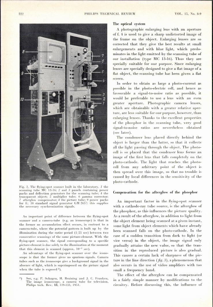
which, disregarding the factor G, represents thearea under the curve 3 in fig. 4. (The dash above thei serves to indicate that the signal current isdistorted as a result of the afterglow. The sameconvention will be used below for other quantities.)As x = Vto' this integration with respect todistance can he replaced by an integration withrespect to time.
The 'result is obtain'ed ill a useful form by intro-ducing the quantity if>, which is the total lightflux at an instant t emitted by the whole screen.Its value is obtained by integration of the lightflux over the' wh~le area of the screen (area under'curve 1, fig. 4): thus if> . V-';CPoj~.Combining·thiswith equation 1, substituting for cp" and changing. the variable to t, the equation for i' becomes
Gk if> t _ t-toi'(t) = --,;_.f a(to)e T dto' (2)
-00
An ideal phosphor, i.e. a phosphor withoutafterglow, would deliver a signal:
i(t) = G kif> a(t) .
The actual phosphor (with afterglow time r). gives rise to the same voltage across the photo-cellresistor Rm' as would an ideal phosphor if theresistor were shunted (fig. 5) by a capacitance Cmgiven by
This may be seen as follows. The undistorted currenti(t), (eq. 3) due to the ideal phosphor, flowingthrough the parallel circuit of Rm and Cm, makes acontribution dqo = i(to)dto to the charging of thecondenser in the time interval to, to+dto' In accord-ance with the well-known law of discharge of acondenser, this part of the charge, at a later instanti, will have dropped to
dq(t) =
t-todq e- RmC",o
t-toi(to) e- RmCIIl dto.
Fig. 5. With'a phosphor having an exponential afterglow ~fafterglow time T, the distorted signal current supplies thesame voltage v'(t) across a resistance Rm (fig. Sa) as theundistorted current i(t) would supply across a parallel con-nection (b) of Rm and Cm, where RmCm = T.
The charge dq(t) makes a contribution dv'(t) =dq(t)jCm to the voltage; thus the total voltage atthe capacitor at the moment t is:
t t-to1 f --v'(t) =- i(to) e RmCm dto'Cm
-00
By combining this result with (3), (4) and (2), thevoltage due to the ideal phosphor across Rm-Cm is
v'(t) = e; i'(t), •.... '. (5)
which is clearly the voltage across the resistor Rmalone due to the afterglow phosphor (fig. 5).
Application of the afterglow compensation
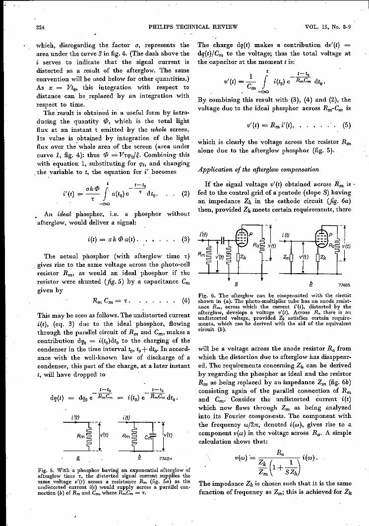
If the signal voltage v'(t) obtained across Rm is .fed to the control grid of a pentode (slope S) havingan impedance Zk in the cathode circuit (fig. 6a)then, provided Zk meets certain requirements, there
(3)-j i(t) -jv(t) v(t)
J Zm J
£! Q 77485
(4)Fig. 6. The afterglow can be compensated with the circuitshown in (a). The photo-multiplier tube has an anode resist-ance Rm, across which the current i'(t), distorted by theafterglow, develops a voltage v'(t). Across Ra there is anundistorted voltage, provided Zk satisfies certain require-ments, which can be derived with the aid of the equivalentcircuit (b).
will be a voltage across the anode resistor Ra fromwhich the distortion due to afterglow has disappear-ed. The requirements concerning Zk can be derivedby regarding the phosphor as ideal and the resistorRm as being replaced by an impedance Zm (fig. 6b)consisting again of the parallel connection of Rmand Cm. Consider the undistorted current i(t)which now flows through Zm as being analyzedinto its Fourier components. The component withthe frequency wj2:n:, denoted i(w), gives rise to acomponent v(w) in the voltage across Ra. A simplecalculation shows that:
R

FEBRUARY-MARCH 1954 FLYING-SPOT SCANNER 225
analogously with Zm, by connecting in parallel aresistance Rk and a capacitance Ck,where RkCk = r.In the coefficient' of i(w) in the above expression,therefore, only one frequency-dependent termoccurs, viz. l/SZk. However, Sand Zk can be madeso large that throughout the whole frequency rangethis term is negligible with respect to unity. Hencethe relation between v(w) and i(w) is independentof the frequency. The voltage v(t) is then propor-tional to the undistorted ,signal current i(t), i.e.the distortion caused by the afterglow has beeneliminated.
Phosphors with non-exponential afterglow
The afterglow behavior of the majority ofphosphors is not exactly an exponential function asassumed above; in many cases the true afterglowphenomenon can be fairly accurately described asthe sum of two, three or still more of these func-tions. The phosphor may then be imagined com-posed of a corresponding number of componentswith afterglow times "1' "2' etc., which give rise tolight fluxes of 1/>1' 1/>2' etc. The current supplied bythe photo-electric cell therefore consists of the sumof the currents which would be generated by e~chof the components separately, and across theresistor Rm there is a voltage equal to the sum ofthe voltages corresponding to each of these currents.Separate RC networks must now be incorporatedin Zm (fig. 6b) for each component of the phosphor,of RC values equal to the afterglow periods of the'corresponding phosphor component, i.e.
These RC networks must be connected in series 'so. .as to give a total voltage equal to the sum of thevoltages corresponding to the various phosphorcomponents. The magnitudes of the componentvoltages are in correct proportion when
where
The current il'(t), originating from the first phosphorcomponent is found by substituting (Pl and Tl for (P and T
in (2). In formula (3), however, (P represents the totallightflux of all the phosphor components together, thus here (P
must be replaced by (Ptot. With the modified formulae (2) and(3) the expression (5) becomes
V '(t) _ Rml m "( )1 - (Pl "'lol' t ;
e'
which is the voltage corresponding to the phosphor componentwith afterglow time Tl and light flux (Pt'
If (6b) is satisfied, then Vl'(t) = Rmil'(t), which is equal tothe voltage cre~ted by the first phosphor component across Rm.
The requirements which the impedance Zk(fig. 6) has to meet remain the same as in the caseof a phosphor with a truly exponential afterglow.
Zk must show the same dependence on the fre-quency as Z,n. and must therefore consist, like Zm,of a number of RC networks connected in series.The RC network in Zk that compensates for aphosphor component with an -afterglow time .1'must have an RC value equal to "1 etc., whilst theresistances in Zk must be in the ratio 1/>1 : 1/>2: •••Moreover, these resistances must be chosen so greatthat l/SZk is negligible withrespect to unity in thefrequency range used.
Another, and in principle, more simple method of compen-sating the afterglow effect is to feed the distorted signalcurrent directly into a correction impedance Ze. With aphosphor of exponential afterglow, it is found that a seriesconnection of a resistance Re and self inductance Le must betaken for Ze, such that Le/Re = T. With a non-exponentialafterglow, for each phosphor component such an LR networkmust he incorporated, and all members eonnected in parallel.The resistances must then be inversely proportional to thecorresponding (P values. The self-capacitances of the coilsand the stray capacitnnces of the multiplier tube, however,cause difficulties, so that in practice the method describedearlier is more satisfactory.
(6b)
The signal-to-noise ratio
In spite of the fact that afterglow compensationhas been achieved relatively simply, it must not beconcluded that no difficulties remain. In the firstinstance, the signal-to-noise ratio is unfavourablyinfluenced by the unavoidable compensation for theafterglow; furthermore, after sharp transitions fromwhite to black, so-called "noise smears" becomevisible.
In order to obtain some insight into the cause ofthe deterioration in signal-to-noise ratio, consider aphosphor with exponential afterglow. A glance atfig. 5 shows that the distortion of the signal currentresults from a reduced signal at the high frequen-cies (influence of the capacitor Cm)' The working ofthe compensation circuit depends upon the fa~t thatit has to give an amplification increasing with thefrequency (w/2n), viz. proportionately to -v 1+W2•2,
Superimposed on the signal current is a noise currentcreated by incidental fluctuations in the emission of 'electrons in the. multiplier tube. This gives rise tothe occurrence of spots in the image. The averagevalue of the noise current is zero. In accordanceWith the theory of n~ise,' the noise current contains

;' :.226 PHILIPS TECHNICAL REVIEW VOL. 15, No. '8-9 '
equal Fourier components of all frequencies up' tothe highest passed by the amplifier (flat noise spec-spectrum, fig. 7). The compensation circuit, whichgives an amplification proportional to VI + a)21:'2,also amplifies the noise proportional to this factor.
• I--------_j
Ia' I
(,Jmax77487 _W
Fig. 7. Noise spectrum before and after compensation of theafterglow. The amplitude factor a' of the Fourier spectrumof the noise current is given as a function of the 'angularfrequency by a horizontal straight line. This is valid up tothe highest frequency passed by the amplifier (Wmnx/2n).After the frequency-dependent amplification, required, forcompensating the afterglow, a' becomes the amplitude factorA, which increases with the frequency. Using a phosphorwithout ,afterglow, the form of A would be given by thebroken horizontal line.
.'
The gréater 1:', the steeper the noise spectrum riseswith frequency. If an ideal phosphor (without after-glow) were used, the amplification would be inde-pendent of the frequency, so that after amplifica-tion, the noise spectrum would again he givenby a horizontal straight line (shown dotted in fig. 7),From this it can be seen that the longer the afterglowtime, the more noise occurs, since the amplificationmust then be made more dependent on the fre-quency.The signal-to-noise ratio which serves as a
measure of the quality of signal, is defined as theratio of the signal current to the r.m.s. value of thenoise current. The theory of the noise of a multi-plier tube confirms the plausible assumption thatthe signal-to-noise ratio will be more favourablefor a large than for a small signal current. Since thesignal current is proportional to the light flux fallingon the photo-cathode, which itself is proportionalto the efficiency of the phosphor, a high efficiencyhas a favourable influence on the signal-to-noiseratio.' The detrimental effect of long afterglow timeon the noise in the whole image can therefore becompensated by a high efficiency 'YJ. It may he shownthat, ~s far this phenomenon is concerned, for nottoo small values of 1:'( 1:'> 3 X 10⁻⁷ sec) the quantityi17/1:' can be 'regarded as a quality factor for thephosphor. For very small values of 1:', the influenceof 1:' is less than is expressed by this factor.
The r.m.s. value of the noise current which issuperimposed on the signal current of a multiplier'tube, is proportional to the square root of the signalcurrent. The signal-to-noise' ratio is consequently
likewise proportional to this square root. Thuswith a strong signal, the signal-to-noise ratio ishigher than with a weak one; this was alreadypointed out in the previous paragraph and stillholds good, in spite of the fact that with a strongsignal, the noise itself is stronger, This fact causesthe "noise smears", which are the second undesirableconsequence of the afterglow.If a light object element in the transparency
(strong signal) is followed suddenly by a darkelement (weak signal) then, as a result of the after-,glow, the signal current in the multiplier tubedecreases exponentially, instead of as 'a suddendrop in level(fig. Ba). The r.m.s. value of the noisecurrent also decreases exponentially (fig. Sb). Thecompensation circuit restores the sudden jump inthe signal current (fig. 8e), but the shape of thecurve of the noise current remains unchanged(fig. 8d). The signal-to-noise ratio is' thus partic-ularly low for a moment, and then rises graduallyto the value corresponding to the dark part of the'image (fig. Se). When using a phosphor with along afterglow time, (with frequency-dependentamplification) "noise smears" are therefore seenin those dark parts of the image which have beenscanned immediately after a light object element'in the transparency.
77488
t i'{t) \_-- ÎI(t)
_t f _t
Ir(tjÎt iMl' --l!. _t !i. _t
tK~,g -t
Fig. 8. The creation of ','noise smears" after sharp transitionsfrom light to dark. The signal current i' has the shape drawnin (a) (i.e. exponential), due to the afterglow. The r.m.s. valueir' of the noise current, which is superimposed on i', is propor-tional to JIii and has an even longer and flatter trailing edgethan i' itself (b). As a result of the frequency-dependentamplification, i' is changed into the form I (fig. c), but ir'is changed into Ir without the shape being modified (d). Thesignal-to-noise ratio K = IJ Ir has, therefore, a very low valuedirectly after the transition (e).
,The noise smears gradually decrease in the direc-tion of the scanning movement.
In the case of a sudden jump from dark to lightin the object, the effect is reversed; the signal-to-noise ratio is then for a moment relatively too high.Naturally, this is not detrimental.

FEBRUARY-MARCH 1954 FLYING-SPOT SCANNER 227 •
With a phosphor having, e.g. an afterglow timeof 10-5 sec, the "noise smears" have a length ofapprox. 1/6th of the total image width after awhite-black jump. In principle the same effectoccurs for a phosphor with a very short afterglowtime, e.g. 10-7 sec; the length, however, of the noisesmears is then of the same order of magnitude asthe size of the image elements, and the smears .aretherefore invisible. ..
From this it can he seen that even though phos-phors have the same quality factor fiI/i, the onewith the shorter afterglow time is to he preferred.
Closer consideration of the quality factor J(fj/,r:
As has already been mentioned, the amplitude factora'(co) of the spectrum of noise current in the multiplier tubeis independent of the frequency (fig. 7) and proportional tothe square root of the instantaneous value of the signalcurrent i', i.e.
a'(w) oe Jlf.After the compensation for the afterglow, a'(co) changes
into:
It can be proved, quite generally, that the r.m.s. valueof a current with amplitude factor A(w) is given by
Since only the frequencies passed by the amplifiers are ofimportance to us, the upper limit of integration can, in ourcase, be replaced by Wmnx. For the r.m.s, value Ir of the noisecurrent after the compensation of the afterglow, we obtainby integration:
For simplicity, assume that a part of the object withconstant transparency is scanned. The generated signalcurrent i is then constant. (Because now there is no differencebetween distorted and undistorted signal currents, i may bewritten for f.) For the signal-to-noise ratio J( in the currentafter the compensation, we have
Since i is proportional to 1), the efficiency of the phosphor,it follows that
If C02mnx .. 2 ~ 1, this reduces to .
fiïJ( oe ---.,-- .
7:(,l)max. t
In the case of a television system with 625 lines, Wmnx/2n =5 Mc/s, from which it follows that .. must be considerablygreater than 0.6 X 10⁻⁷ sec for this approximation to bevalid.
We have therefore, that K is approximately proportional toJIn / r, Further, J( is approximately inversely proportional towmnx'I., and since COmnx is proportional to N2 (N representsthe number of lines), J( is 'roughly inversely proportional toN3. With a greater number of lines, therefore, the phosphormust meet much higher requirements, or more noise must betolerated in the image. The signal-to-noise ratio calculatedfor th~ apparatus illustratèd in fig. 2, with a transparencya = 0.6 of the object, has the very high value of roughly 120,thanks to the very short afterglow time of the phosphor used«10-7 sec.). In the darkest parts of the image, where thetranspareney is, say, 100 times less, the signal-to-noise ratiois 1'100 times less, i.e. still 12.
The gamma corrector
After the compensation of the afterglow effect,the flying spot scanner gives a signal VI that islinearly proportional to the transparency ap of theobject (p = positive), i.e,
(7)
The brightness Bw on a receiver picture-tube,however, is not proportional to the supplied voltageVw; it is approximately represented by a PQwerfunction
(8)
in which Yw has approximately the value 2.5. It isobvious that it is desirable for the brightness ateach point on the picture tube to be proportionalto the transparency at the corresponding point ofthe object, i.e. we require that
Bw oe apo
To achieve this, the signal VI is passed through a"gamma corrector" before transmission, in whichit suffers linear correction, so that the signal Vw onthe picture tube is proportional to VI1'e. One thenfinds, using (8) and (7),
(9)
B oe V YeY,o oe apYeY,ow I. (10)
Comparison of (10) with (9) at once shows that Yemust he equal to l/yw for (9) to be satisfied.It is not always possible to realize exactly the
proportionality expressed in (9). This fact is con-nected witli brightness range ór contrast ratio of theobject. The contrast ratio of an object (or image). is the ratio of the highest level of brightness to thelowest level of brightness. For a transparency, wedefine this quantity as the ratio between themaximum and the minimum optical ira~smission.The maximum contrast ratio attainable in practiceon the screen of a picture-tube is not greater than100. On the one hand the maximum brightnesscannot, of course, be raised above à certain value,

I,
~ 228 PHILlPS TECHNICAL REVIEW VOL. IS, No. 8-9
while on the other hand the minimum brightness isalso limited, even if there is no externallighting, e.g.in a completely darkened room.' Even then, light'from the lighter parts of the image reaches t!tedarker parts via reflection. If the contrast ratio Cof the transparency is greater than 100, it must bereduced to, 'let us say, c, in the general case. The. condition (9) cannot, therefore, be fulfilled, and toobtain as faithful an image as possible, it is best ifthe reduction in contrast is distributed over thewhole brightness range in such a way that in placeof (9) we obtain the relation:
where, log cYtotn! = I-C'. og
The fact that the relationship between Bw and apmust have precisely this form is linked with thecharacteristics of the human eye.
It is an empirically established fact that the impressionwhieh the eye obtains from a transition from light to dark ina picture is not determined by the variati~n of the brightnessb with position, viz. not by dbJdx, but by the relativebrightness variation per unit length, (dbJdx)Jb. A similarbrightness difference between two adjacent points thereforeappears to the eye of proportionately lower contrast as thelocal brightness level is higher (this is the reason why, e.g,the auditorium is darkened for the showing of films).In the reproduetion of the image, for example, on the
screen of a picture tube, it is further found that for a tran-sition from light to dark, one gets exactly the same impressionif (dBJdx)JB = P (dbJdx)Jb (B and X in the reproduetioncorrespond with b and x in the original image; p is a constantwhich may differfromunity.) IfX = mx, i.e. if m is the linearmagnification of the reproduetion with respect to the originalimage, then dBJB must be equal to m PdbJb.By integration it isfound from this that for a faithful reproduetion (mp = Ytotn!):
Boe bYto!.!. . . . . . . . . (13)
If, e.g. 'Ytotn! = 2.3, then it is said that the "gamma" ofthe apparatus with which the reproduetion is made, is 2.3.If, as with the flying-spot scanner, çne starts from a trans-
parency as' object, then the optical transmission up of thistransparency assumes the part of the brightness b in theoriginal image, and (13) is therefore equivalent to (11).Inserting actual values in (13) of the brightnesses in the
original and in the reproduced image, first for the lowestbrightness levels ~nd then for the maximum brightness'levels, gives two equations, which divided byeach other'andequated to the contrast ratio of both images logeJlogC,leads to equation (12).
The requirement (11) thus takes the place of(9). Comparison of (11) 'with (10) at once showsthat for (11) to be satisfied, we must have
Ytota! = Ye' Yw' . . .. (14)
(11)
In order to be able to adjust Ytotu! to the requiredvalue (12), Yemust be variable. If the contrast ratioof the transparency is 100 or less, then the samecontrast ratio can be realized in the image, i.e, one,can select Ytotn! equal to unity, as already mention-ed. Since in our case Yw ;- 2.5, it is required thatYe= 0.4. If the contrast ratio in the transparencyis greater than 100, then this factor must bereduced in the image; therefore Ytotu! must besmaller than unity. It is also sometimes required toincrease somewhat the constrasts 'of transparenciesthat have been printed too "soft", i.e. to increasethe contrast factor. In this case Ytotnl must begreater than unity. The apparatus described isbased on the requirement that Yemust be variablebetween 0.2 and 0.6.
(12)
Construction of the gamma corrector
The electron beam in the scanning tube issuppressed during the flyback period. During thisperiod the signal given by the flying-spot scannercorresponds to absolute black in the transparency.This period of blackness is used to fix the absoluteblack level on the picture-tube too; the black levelis therefore independent- of the adjustment of thegamma corrector. In practice, it is necessary thatthe white level on the picture-tube is also indepen-dent of the adjustment of the gamma corrector: avariation of the level with Yewould make it difficultto judge the effect of Yadjustment on image quality.To achieve this independence, the series of charac-teristics Ve= Aev?e (seefig. 9a) must interseet each
I'twhite79563
Fig. 9 a) Characteristics required of the gamma corrector(output voltage Ve as a function of. the input voltage VI).The curves are power functions of the form Ve = Ae • VI)'e.The input signal VI white corresponds to "white" in the image.It is required that, with variations of 'Ye, the point with co-ordinates Vlwhi!e, Vewhite, remains invariant; to achieve this,Ae must depend upon ye in a definite manner.b) Example of the gamma corrector characteristics if nospecial measures are taken to make Vewhite independent of'Ye. The variation of Vewhite with ye now interferes with thejudgment of the effeet of a variation of Ye.

FEBRUARY-MARCH 1954 FLYING-SPOT SCANNER 229
other at the fixed point Vlwhite' VCwhite' This impliesthat, the proportionality constant Ac must be adefinite function of Ye, viz. Ac = (Vewhite) (VlwhitetYe•
In many gamma corrector circuits, no . specialprovisions are made in this respect, so that Ac isa different function of Ye than that desired; thecharacteristics of the corrector then have the formsas shown in fig. 9b.In the circuit to be described this requirement
has been met in a very simple manner. The signalVz coming from the flying-spot scanner is fed to thecontrol grid of the p~ntode P (fig. 10), with a
77490
Fig. 10. Circuit diagram of the gamma corrector. The signalVI, from the flying-spot scanner, corrected for afterglow, isapplied to the grid of the pentode P, which, with the aid ofa special circuit (not shown here), is so adjusted that the anodecurrent has a low, fixed value when the signal VI = vz blnck(flybaek period). The shape of the overall eharacteristic(iatotnl as a function of VI) can be modified by varying R2and R3' This curve is constructed in fig. 11.
polarity such that the anode current of this tubeincreases with increasing VZ, i.e. with increasingbrightness in the object. Moreover, with the aidof a special circuit (not mentioned here or in fig. 10),this tube is so adjusted that when th~ flying-spotscanner gives. the signal corresponding to absoluteblack (flyback periods), the anode current of Phas a fixed, small value. The relation between theinput voltage VI and the output voltage Vc of this
, circuit then has the desired form (fig. 9a) to a verygood approximation. The value of t'c is set with theresistors R2 and R3, while the constant white levelis obtained by giving Rl a suitable fixed value.Further details are given in figs 10 and 11.
In the case of the signal Vz bleek , the anodecurrent of P is a minimum, and the control gridpotentials of the pentodes I,n and III thus havetheir maximum values, which are equal to the com-mon cathode potential (if they exceeded this, gridcurrents will flow and charge the capacitors Cl,CII and CIII until the control grids were 'at cathodepotential).
In the graph in fig. lla, the voltage V is plottedalong the abscissa: The origin of the co-ordinates
.- .....:' .•,
has been chosen at the point Vlblnck' The controlgrid potentials VgI, VglI and VglII of the threepentodes are plotted on the negative part of theordinate. (The origin corresponds to the cathodepotential.] As explained above, the grids havecathode potential when Vz = VZblnck' and the curvesfor "s as a function of Vz in the fourth quadrantthus pass through the origin. Further, all threeare of the same shape as the ia-vg characteristicof the tube P, vgI, VglI and VgllI being linearlyproportional to the anode current through thistube. The slopes are in the ratio of Rl : R2 : R3'In the third quadrant is plotted the ia-vg charac-
teristic of the pentodes I, n and TlI, which forsimplicity are regarded as identical. In fig. lla, Rlhas been so selected that at Vlwhite' the anodecurrent of tube I is exactly zero. (It is not essen-tial that, at Vz white' the anode current should beexactly zero.) The curves in the first quadranthave been constructed from those in the fourthquadrant with the aid of the ia-vg characteristicshown in the' third quadrant. These curves (firstquadrant) indicate the relation between Vz and theanode currents in the tube I, Tl and Ill. Byaddi-tion of the three curves, the total anode currentiatotnl through' the common anode resistance Ra isobtained as a function of Vz. If the tappings R2 andR3 are adjusted, the points P2 and P3 shift alongthe Vlwhite axis. The curves ialI and ialII (in thefirst quadrant) then turn about the point 01' andthe portions 11 and 111 of the iatotnl curve turnabout the points O2 and 03 respectively, 'I'hus the
Vcwhitel-------~
~Î
79564
Fig. 11. Construction' of the overall characteristic of thegamma corrector circuit shown in fig. 10.a) In the fourth quadrant (lower right), the control gridvoltages Vgl, VgII and VgIIl of the pentodes 1, II and IIIare plotted as functions of vz. The third quadrant containsthe anode-current/control-grid voltage characteristic of eachof these three pentodes (assumed identical). From the abovecurves, the anode currents i-a, i-ai and istu are constructedin the first quadrant as a function of VI. The total ,anodecurrent i.total is obtained by addition.b) The characteristic of the gamma corrector of fig. 10.As theoutput voltage Vc is opposite in sign to i.total (vc = -ia'totnIRa),·the characteristic required is obtained from the ia total-VI curveby taking its mirror image in the abscissa.

230 PHILIPS TECHNICAL REVIEW VOL. 15, No. 8-9
output voltage Vc of this gamma corrector, Vc =-ia total X Ra. (The minus sign results from thephase reversal which occurs in the tube when theoutput signal is taken from the anode).The shape of the curve which determines the
relation between v~ and VI is thus obtained bymaking a mirror image of the iato'.l curve (fig. lla)with respect to the abscissa (fig.llb). Fig. 12 shows(for two values of Ye) how this shape can be fittedto the one required by adjusting R2 and R3'The characteristic of the gamma corrector can
be displayed on the screen of a cathode-rayoscilloscope. A sawtooth voltage serves as VI' andis also used for the horizontal deflection on theoscilloscope, while the output voltage Vc controls thevertical deflection. In fig. 13 some curves arereproduced which were obtained by this method,while fig. 14 gives an impression of the influencewhich the gamma correction exercises on the picture.By connecting four or more pentodes in parallelinstead of three, a still better approximation tothe required characteristic is possible.
shape of the ia tot curve is variable, but the extre-mity at black (03) remains in its place. Similarlythe extremity at white remains fixed (providedVI white corresponds to a point on the fixed part Iof the curve; to ensure this, the anode current, forVI white' should be zero, or a small value). Becausethe tube characteristic from which the ia tot curveis derived are not exactly straight, nor the cut-offvalue sharply defined, the actual curve is notsharply bent, but rather, bends gradually. For the
79565
The reproduetion of negatives
It is perhaps surprising that with the flying-spotscanner as described, it is also possible directly toreproduce the positive picture by scanning anegative. In order to see how this may be done,first consider again a positive object transparency.It should be noted that what is required in the finalimage is a faithful reproduction, with tone contrast,of the original scene printed on the transparency,rather than a true reproduction of the transparencyitself. To make the transparency, it is usual tofirst make a negative of the original scene by normal
~black
'1black
Fig. 12. Approximation to the required characteristics withthe gamma corrector. The full lines show the desired charac-teristics, for Ye = 0.2 and 0.6. The broken lines represent theapproximations to these curves; in practice the sharp bendsare rounded off, cf. fig. 13.
'1 white
abcFig. 13. Oscillograms showing the approximations of the gamma corrector to the exactcharacteristics, for different values of ye. The exact curves are drawn in thin lines forYe = 0.2, 0.3 and 0.4.
-

FEBRUARY-MARCH 1954 FLYING-SPOT SCANNER 231
a bFig. 14. Image on the picture tube (a) without and (b) with gamma correction. The con-trast ratio of the object was so great that the gamma of the corrector had to be set toapproximately 0.3.
photographic methods. It is a characteristic of thephotographic process that the transparency an inthe negative is related to the brightness Bs of thecorresponding part of the scene according to
Here, Yn has a value between -0.4 and -0.8.That Yn is negative follows from the fact that ahigh brightness in the scene corresponds to a lowtransparency in the negative 4). The positive print(= the "transparency") is made photographicallyfrom the negative; the transparency ap of the posi-tive is related to an according to a similar expres-SIon,
Here again r» is negative.We have already seen that ap is transformed
into the brightness Bw on the picture-tube via apower function (10). The complete transformationof Bs to Bw occurs, therefore, as a product of powerfunctions, the total transformation being representedby:
Bw oe B/total,. . . • • • (15)
where Ytotsl is equal to the product of the exponentsof the subsequent transformations. Therefore
Ytotal = Yn' Yp . Ye' Yw .
Ytotsl must be positive, because a negative Ytotal
would mean that a negative image appears on thetube (i.e. a large B; would give rise to a small Bw,
4) The reader who is acquainted with photographic pro-cesses will, perhaps, take offence at the introduetion ofnegative gammas. The negative values are the result ofthe use of the transparency a, in place of the blackeningusual in photography.
eq. (15)). YIt and Yp are both negative, and Yw ispositive, so that the Ye of the gamma correctormust be made positive.
If now we use a negative transparency as objectin the flying spot scanner,
Ytotal = Yn' Ye· Yw'
In order now to obtain a positive Ytotal' Ye must benegative, which means that the characteristic of thegamma corrector should be as in fig. 15. This form
ivc
t;,= -0,5
77507
Fig. IS. The function Vc oe v/ye for negative values of Ye.
may be derived from the characteristic of the (posi-tive object) gamma corrector (fig. Ub) by takingthe image of the latter in a line parallel to theabscissa. The "mirroring" is achieved by adding anextra tube behind the gamma corrector to give aphase reversal. With the adjustments provided onthe gamma corrector, the shape of the ideal charac-

232 PHILIPS TECHNICAL REVIEW VOL. 15, No. 8-9
teristic can now hé attained to a sufficient approxi-mation.There' is still a complication in that, during the
flyback times, no current flows in the photo-electriccell; for negatives this corresponds to the brightestwhite. In order to suppress the 'flyback on thepicture tube, image blanking pulses' having anamplitude equal to the maximum "white" signalmust therefore be added to the signal.
It might at fust appear that the gamma correction of anegative object could also he achieved by reversal of theinput signalof the gamma corrector instead of the outputsignal. Upon closer examination, however, this is found notto be the' case, since reversal of the signal means that Vc
changes into Vo-Ve where Vo is a constant reference level.Reversal thus corresponds to subtraction of a constant, thegamma corrector then raising the signal to the power Ye.Because these operations are non-commutative, the order inwhich they are carried out will influence the final result.
The apparatus discussed is useful whenever animage signalof very good quality is required, viz.in laboratories and in factories engaged in themanufacture of TV apparatus. A direct, practicalapplication in the TV studio is the transmitting of
-Iantern slides, such as the test pattern, or themeteorological map, and of drawings and photo-graphs for the illustration of talks. An importantapplication is undoubtedly the transmitting offilms. The complications encountered in the latterwill he discussed in a later issue of this Review.
Summary. For the generating of TV signals from flat trans-parent objects (lantern slides, transparencies, microscopeslides etc.), a flying-spot scanner has been developed, inwhich the light source is the light spot of a cathode-ray tube(the scanning tube) specially adapted for the purpose. Imagesof very good quality can he obtained with this apparatus:distortion-free, very sharp and with good gradation. Theinfluence of the unavoidable afterglow of the phosphor ofthe scanning tube can be compensated by an amplificationwhich varies in a- specified way with the frequency. Since,however, the signal-to-noise ratio is unfavourably influencedby this, the scanning tube is provided with a phosphor havinga very short afterglow time. Mter compensation of theafterglow, the flying-spot scanner supplies a signal that isproportional to the transparency of the object to be reproduced,Because of the non-linear characteristic of receiver picturetubes, the signal must be corrected in order to obtain afaithful picture on the TV screen. This is done with the aid ofa .so-called gamma corrector which, moreover, is designed toprovide additional correction in the case of a transparencywhich is too contrasty or too soft. A particularly simple andpractical circuit has been designed for this gamma corrector.By means of a simple modification to the gamma corrector,negatives can be scanned directly and reproduced as positiveimages.