Progress in Clinical Research (Linda-Gail Bekker MBChB, DTMH, DCH, FCP(SA), PhD.)
Study of Earthing System Characteristics Under Low Frequency and Transient
ConditionsBy
Buba, Sani DahiruGS34084
Supervised by,
Dr. Wan Fatinhamamah Wan AhmadAssoc. Prof. Dr. Chandima Gomes

Presentation outline
Introduction on proposed research topic
Progress in the current semester
OverviewTypes of earthing system;
functional earthing system, specific to sensitive electronic equipment and data networks
system earthing, neutral point of a transformer equipment earthing, connection of metallic parts
to ground. protective earthing refers to bonding of all
exposed metallic and extraneous conductive parts.

Introduction contd.Substation Earthing;
The substation earthing system is necessary for connecting neutral points of transformers and generators to ground.
For connecting the non-current carrying metal parts such as structures, overhead shielding wires, tanks, frames, etc. to ground.

Introduction contd. The substation earthing system provides a
grounding mat below the earth surface in and around the substation.
Provides uniform zero potential with respect to ground and lower earth resistance.

Introduction contd.Substations are basically classified based on,
1. Voltage level, e.g. A.C Substation: EHV, HV, MV, LV or, HVDC Substation
2. Indoor or Outdoor, Indoor substations are sited within buildings, while Outdoor Substations are under the open sky.
3. Configuration, conventional air insulated out door, SF6 Gas
insulated Substation (GIS), or composite Substations combining the two.

4. Application,
Step Up Substation; associated with generating stations. step up voltages from 16-25kV to EHV or HV.
Primary grid Substation; installed at suitable load centre along the primary transmission line. Receive power from EHV lines at 400kV, 220kV, 132kV and transform to 66kV, 33kV or 22kV.
Secondary Substation; installed along secondary transmission line, working voltages 66/33kV further stepped down to 11kV.
Distribution substation; installed where transmission line voltage is stepped down to secondary distribution voltage.
Bulk supply or Industrial Substation; are mostly dedicated Substations.

Figure 2 Typical substation switch yard
General problem statement
All the earthing systems mentioned earlier exist in a typical Substation, i.e. system earthing, functional earthing, protective earthing and equipment earthing.
Should the earthing systems be separated or integrated?
A typical scenario

Separated/isolated earthingIt is reported in IEEE Std. 142:2007 that,
The power earthing system has been found to cause malfunctions and failures of electronic equipment.
A logical solution was not to use the equipment earthing system for grounding electronic equipments.
The chosen alternative was to earth electronic equipment through an isolated earthing electrode consisting of one or more driven rods separate from the power system earthing electrode system.

Separated/isolated contd.
This electrical separation of earthing electrodes without bonding all earthing electrodes together violates (National Electric Code) NEC requirements
While continuous low-level noise was eliminated by the isolated earth practice, a number of catastrophic incidents were encountered.

Separated/isolated contd.
Analysis indicated that, separation of earthing was responsible for very large voltages being impressed on electronic equipment components under thunderstorm conditions.
These voltages occurred whether or not electronic equipment were in operation.
The large voltages were due to lightning striking either the building housing the electronic equipment or the power system serving the building.

Integration of earthing systems
When the electronic equipment earthing electrode and the electrical power system earthing electrode are connected together, an applied transient voltage will result in the entire electronic equipment system rising and falling at the same potential.
No overvoltage will be induced into the electronic equipment circuits.

National Electric Code (NEC) USA, and European standard HD 631S1-1991E, IEEE Std. 80:2000, IEEE Std. 142:2007 all advocate for integration of earthing systems within a substation.
Other local standards have recommended separation of earthing systems, some by 3m (New South Wales Technical ref. EES005) some by 4m (Saudi Arabian Distribution Code). Why the differences in distance?

Integration contd.
A serious hazard that may result from an integrated earthing system is the transfer of potential between the substation ground grid area and outside locations during a ground fault.
This transferred potential may be transmitted by communication circuits, conduit, pipes, metallic fences, low-voltage neutral wires, etc.
Potentials may also be transferred by coupling.

Proposed StudyResponse of Separated Grounding Systems Under Low
Frequency and Transient Conditions
To be studied under,
Different soil conditions Different equipment conditions,
Power system substation Communication tower
Study contd.Methodology of study
Simulation using ATP-EMTP software CDEGS software/resistivity measurement Experiment using scale model
A formal proposal is in writing process and would be presented to my supervisory committee soon.
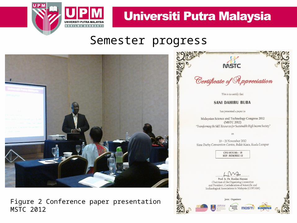
Semester progress
Figure 2 Conference paper presentation MSTC 2012


Thank you


![Modeling and Optimization of Resource Allocation in Cloud [PhD Thesis Progress 1]](https://static.fdocuments.in/doc/165x107/55a676a61a28abb6758b45a5/modeling-and-optimization-of-resource-allocation-in-cloud-phd-thesis-progress-1.jpg)