Ph.D. candidate, Department of Civil Structural and...
7
MCEER Student Research Accomplishments POLYMER MATRIX COMPOSITE (PMC) INFILL WALLS FOR SEISMIC RETROFIT WOOYOUNG JUNG Ph.D. candidate, Department of Civil Structural and Environmental Engineering, University at Buffalo Background/Motivation Civil engineers have recognized the potential of advanced polymer composites as an alternative material for construction. Driven in particular by the recognition that composites can offer improved advantages over traditional materials such as steel and concrete, attempts to use composites for buildings and bridges are on the rise. While it is apparent that fiber reinforced polymer (FRP) composites play an increasingly important role in civil engineering applications, there is even a greater promise for the new concept of joining composites with traditional materials to form hybrid structures. In recent years, PMC materials have been selectively used to retrofit structural elements such as wrapping of concrete columns to enhance strength and ductility. However, the use of such material in a large-scale structural system to resist seismic excitations has been very scarce. The limited use is mainly due to economical factors, lack of standards for PMC wall design and questions related to longevity. Our goal in this research is to study the effective application of composite material when combined with steel frames and to generate optimum seismic retrofit strategies using PMC infill walls. Previous Research Typically, some low and middle rise building frames have infill wall systems. The infill walls have been built after the frame is constructed as partitions and in some cases infill walls are parts of the structural system. As a matter of fact, there is no resemblance between the response of the infilled frame and the bare one, as the former is substantially stronger and stiffer than the latter. Around 1950’s, the behavior of infilled frames had been investigated by Benjamin and Williams (1957, 1958). Since that time, Mainstone (1971), Liauw et al. (1985) and White et al. (1997) studied the role of infill walls in strengthening and stiffening the structure as a whole. As a result, the effects of neglecting the infill walls are accentuated in high seismic regions where the frame/wall interaction may cause substantial increase of stiffness resulting in possible changes in the seismic demand, and the infilled frame structure typically exhibits changes in the magnitude and distribution of stresses in the frame members. For the infill wall system with composite material, Gasparini, Curry and Debchaudhury (1981) presented the damping of frame with visco-elastic infill panels for increasing damping and 21
Transcript of Ph.D. candidate, Department of Civil Structural and...

MCEER Student Research Accomplishments
POLYMER MATRIX COMPOSITE (PMC) INFILL WALLS FOR SEISMIC RET
WOOYOUNG
Ph.D. candidate, Department of Civil Structural and Environmental Engi
University a
Background/Motivation
Civil engineers have recognized the potential of advanced polymer composites as an al
material for construction. Driven in particular by the recognition that composites can offer i
advantages over traditional materials such as steel and concrete, attempts to use compo
buildings and bridges are on the rise. While it is apparent that fiber reinforced polyme
composites play an increasingly important role in civil engineering applications, there is even
promise for the new concept of joining composites with traditional materials to form hybrid st
In recent years, PMC materials have been selectively used to retrofit structural elements
wrapping of concrete columns to enhance strength and ductility. However, the use of such m
a large-scale structural system to resist seismic excitations has been very scarce. The limit
mainly due to economical factors, lack of standards for PMC wall design and questions r
longevity. Our goal in this research is to study the effective application of composite mater
combined with steel frames and to generate optimum seismic retrofit strategies using PMC in
Previous Research
Typically, some low and middle rise building frames have infill wall systems. The infill w
been built after the frame is constructed as partitions and in some cases infill walls are par
structural system. As a matter of fact, there is no resemblance between the response of the
frame and the bare one, as the former is substantially stronger and stiffer than the latter.
1950’s, the behavior of infilled frames had been investigated by Benjamin and Williams (195
Since that time, Mainstone (1971), Liauw et al. (1985) and White et al. (1997) studied the rol
walls in strengthening and stiffening the structure as a whole. As a result, the effects of negle
infill walls are accentuated in high seismic regions where the frame/wall interaction m
substantial increase of stiffness resulting in possible changes in the seismic demand, and th
frame structure typically exhibits changes in the magnitude and distribution of stresses in t
members. For the infill wall system with composite material, Gasparini, Curry and Debch
(1981) presented the damping of frame with visco-elastic infill panels for increasing dam
21
ROFITJUNG
neering,
t Buffalo
ternative
mproved
sites for
r (FRP)
a greater
ructures.
such as
aterial in
ed use is
elated to
ial when
fill walls.
alls have
ts of the
infilled
Around
7, 1958).
e of infill
cting the
ay cause
e infilled
he frame
audhury
ping and

MCEER Student Research Accomplishments
minimizing vibration. Recently, Haroun, Ghoneam, and Essam (1997) studied the effects of
strengthening and repairing masonry infilled reinforced concrete frames by fiberglass composite.
Justification & Objective
This research addresses the design, fabrication and testing of polymer matrix composite (PMC) infill
walls for use as a seismic energy dissipation strategy. For the proposed technique, we have introduced
a multi-layer system allowing in plane shear and therefore sliding along specific layers to take place
upon loading the frame. Finally, we anticipate the damage to be controlled in such layers, thereby,
allowing us to reuse the wall components. In order to meet the best result, we plan to consider several
design cases to increase the capacity of the damaged layers by utilizing a combination of (1) visco-
elastic and Honeycombs, and (2) visco-elastic and thermoplastic polymer materials.
Practically, the new infill PMC wall system may lend itself to the application in seismic areas for three
reasons. First, the material has a high stiffness-to-weight and strength-to-weight ratio. The addition of
infill walls into an existing building will not significantly alter the weight of the structure; therefore,
existing foundations will remain sufficient to carry the gravity loads. Secondly, due to the lightweight
of the walls combined with the idea of prefabrication, rapid construction will be achieved and
interruption to the occupancy of the structure will be minimal. Third, polymers have good damping
characteristics. In designing the walls, polymers that exhibit significant visco-elastic behavior can be
utilized in specific layers of the wall.
Actually, there are several technical and economical challenges associated with the use of PMC in
structural applications such as buildings. Some of the most serious questions surrounding the viability
of PMC structures relate to the availability of tested PMC structural systems to resist seismic loads, the
cost of their construction, availability of standards for their design, practical connection details, and
the feasibility of their construction. In the design process, there were many design variables that
affected both the performance and cost of the infill wall. Having a large number of design variables
and a wide range of materials that can be used presented a great challenge. In this research, a
conceptual optimum design of an infill wall is presented using the finite element analysis. As
mentioned above, the conceptual design is based on using a multi–layer system and allowing for in
plane shear deformations to be concentrated in specific layers. Thereby, damage in such layers will
provide the energy dissipation in the system. Also, the other aspects of the PMC infilled frame system
are considered: (1) studying of properties of FRP and visco–elastic materials, (2) manufacturing the
structural PMC walls, and (3) testing the wall systems when incorporated in a steel frame having
semi–rigid bolted connections.

MCEER Student Research Accomplishments
Progress of Research
1. Material Testing
Fiber reinforcing polymer (FRP) materials were tested to evaluate the mechanical properties that are
needed for analysis and design. The evaluation of the mechanical properties of composites includes
their strength and stiffness characteristics. For tension and compression test, each ultimate tensile,
compression strengths, Young’s modulus and Poison’s ratios were obtained by testing longitudinal
( 0° ) and transverse ( 90° ) specimens according to the ASTM D3039 standard test method for
tension and ASTM standard D3410 for compression. For evaluating in–plane shear properties, the 2–
rail shear test method, as described in ASTM D4255, was used in this research. Also, the visco-elastic
material was tested in this research. It is composed of H8–PP Polypropylene Honeycomb produced by
Nida–Core Corp, FL, combined with a resin–rich layer on each surface of the honeycomb. This is a
hexagonal cell honeycomb extruded from polypropylene. In our research of the honeycomb and resin–
rich layers, the energy dissipation was expected to be through in–plane shear deformation. To
investigate the behavior of honeycomb materials, pure shear test was considered as depicted in Figure
1.
(a) FRP Material Test (b) Visco-elastic Material Test
Figure 1: The Configuration of the Material Tests
2. Design and Construction of Composite Panel
In this section, we present one conceptual application of the PMC wall system. First, a sandwich
construction was considered as a main concept to reduce the weight, sound and vibration as well as to
improve structural rigidity. Based on this concept, the wall system was designed with three panels
forming the entire wall thickness as shown in Figure 2(a). Second, we approached the optimum design
of inner and outer layers composed of laminates based on structural performance. Design of each

MCEER Student Research Accomplishments
laminate layer includes (1) selecting a material system or a group of material systems, (2) determining
the stacking sequence for the laminate based on applied loads, (3) some of the constraints include cost,
weight, and stiffness. For optimum design based on the cost and performance, we have relied on
detailed 3–D finite element models using ABAQUS. Eight node linear brick elements (C3D8) were
used to model both the steel frame and honeycomb materials. Four node shell elements (S4R5) were
used to model the composite laminate wall components. The interface between infill and frame
members was modeled with gap–friction elements which provided gap between the nodes of frame
and the wall along the perimeter. The finite element analysis is used to (1) design the optimum
composite panel (2) develop proper simplified analytical model for composite infill wall frame system
(3) predict the type of anticipated failure mode for subsequent experiments having various visco-
elastic layers and new conceptual wall designs.
Detailed design drawings were delivered to a local PMC manufacturer (AN–COR Industrial Plastics,
Inc., Tonawanda, NY) to construct the PMC infill wall. The PMC wall as shown in Figure 2(b) was
constructed considering the most practical and commercial conditions. After manufacturing, the wall
was installed in a frame (2500x2400 mm, W8x24 column and W8x21 beams) having semi–rigid
bolted connections to be tested.
(a) Multi-layer System (b) Constructed Wall Shape
Figure 2: The Configuration of the PMC Infill Wall
3. Description of the Experiments
In the experimental phase, testing of steel frame with and without composite infill wall is planned as
shown in Figure 3. Steel frame and composite infilled frame specimens were tested under monotonic
and cyclic in–plane loading. To apply lateral force, a 250–kips MTS hydraulic actuator with a stroke
of ±4 inch was used. All cyclic tests were performed under displacement control.

MCEER Student Research Accomplishments
(a) Steel Frame Test Setup (b) The PMC infilled Frame Test Setup
Figure 3: The Configuration of the Bare Frame and PMC Infilled Frame
Various instruments were attached to the specimen to capture key quantities to characterize the
structural response of the composite infill wall and steel frame. These key quantities include the
following: (1) longitudinal and transverse strain at critical point on the composite infill panel, (2) the
shear deformation of the visco-elastic material using linear potentiometers, (3) the hysteretic behavior
and the corresponding strength deterioration and stiffness degradation of steel frame and composite
infilled frame using displacement transducers, and (4) buckling of the PMC inner panel.
Conclusions
Several important results concerning composite energy dissipation of infill panel may be stated. Based
on numerical and experimental results so far, the main conclusion may be drawn as follows:
• Initial stiffness of the PMC infilled frame is 3 times that of the steel frame. And, the load-carrying
capacity of the PMC infilled frame is 4 times that of the steel frame.
6.27
17.69
02468
101214161820
0.0 0.2 0.4 0.6 0.8 1.0 1.2
Drift
Forc
e (K
ips)
Steel-frame
Infilled frame
-40
-30
-20
-10
0
10
20
30
40
-2 -1.5 -1 -0.5 0 0.5 1 1.5 2Drift (%)
Forc
e (K
ips)
Figure 4: The Results of the PMC Infilled Frame Test (Monotonic & Cyclic loading)
Table 1: The Comparison of Each Component
Infilled Frame Steel Frame PMC Infill Wall
Stiffness (Kips/in) 15.65 5.55 10.1
MCEER Student Research Accomplishments
• The total energy dissipation capacity of the PMC infilled frame subjected to small deformation of
visco-elastic layers is 3 times that of the steel frame. The contribution of the PMC infill wall is
65% of overall energy dissipation performance without significant degradation for the stiffness
and strength. It is evident that energy dissipation capacity of the PMC infilled system may be
larger where the visco-elastic layers contribute a relatively large deformation.
0
0.5
1
1.5
2
2.5
3
Total Steel frame Net infill wall
Cycle Number At 0.5% Drift
Ener
gy d
issi
patio
n ca
paci
ty
1st cycle2st cycle
0
2
4
6
8
10
Total Steel frame Net infill wall
Cycle Number At 1.0% Drift
Ener
gy d
issi
patio
n ca
paci
ty
1st cycle2st cycle
0
5
10
15
20
25
Total Steel frame Net infill wall
Cycle Number At 1.5% Drift
Ener
gy d
issi
patio
n ca
paci
ty
1st cycle2st cycle
Figure 5: The Energy Dissipation Capacity for the PMC Infilled Frame (Kips-in)
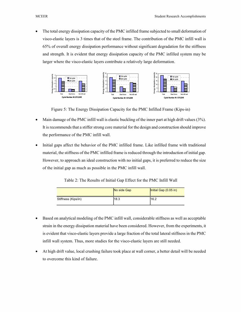
• Main damage of the PMC infill wall is elastic buckling of the inner part at high drift values (3%).
It is recommends that a stiffer strong core material for the design and construction should improve
the performance of the PMC infill wall.
• Initial gaps affect the behavior of the PMC infilled frame. Like infilled frame with traditional
material, the stiffness of the PMC infilled frame is reduced through the introduction of initial gap.
However, to approach an ideal construction with no initial gaps, it is preferred to reduce the size
of the initial gap as much as possible in the PMC infill wall.
Table 2: The Results of Initial Gap Effect for the PMC Infill Wall
No side Gap Initial Gap (0.05 in)
Stiffness (Kips/in) 18.3 16.2
• Based on analytical modeling of the PMC infill wall, considerable stiffness as well as acceptable
strain in the energy dissipation material have been considered. However, from the experiments, it
is evident that visco-elastic layers provide a large fraction of the total lateral stiffness in the PMC
infill wall system. Thus, more studies for the visco-elastic layers are still needed.
• At high drift value, local crushing failure took place at wall corner, a better detail will be needed
to overcome this kind of failure.
MCEER Student Research Accomplishments
Compression
(a) Positive lateral force (Push)
Contact Force (P)
Undeformed Infill wall shape
P
Compression
P
Tension
(b) Negative lateral force (Pull)
Tension Tension Compression
P
P
PCF P
Contact Force (P)
Compression Tension
CF
(a) Behavior of the PMC Infill Wall (b) Failure Modes of the PMC Infill Wall
Figure 6: The Behavior and Failure Modes of the PMC Infill Wall
(a) Corner Crushing Damage (b) Elastic Buckling of the PMC Infill Wall
Figure 7: The Damages of the PMC Infill Wall
Future Study
Additional research is required based on the first test. Especially, advanced modeling related to the
structural performance and economic application will be needed. Practically, light and flexible
building systems often require specific design features for limiting structural damage, structural
control for the vibration, and maximizing occupant comfort and safety. Consequently, our research
plans include the following:
• Study the behavior of several composite infill wall systems from the experiment.
• Develop simplified analytical modeling from the experimental results.
• Study and test advanced interfacing materials under seismic excitation.
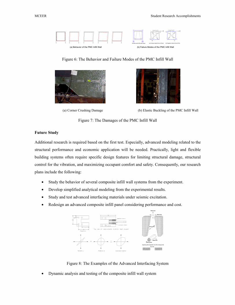
• Redesign an advanced composite infill panel considering performance and cost.
Injecting thermoplastic into the honeycomb
Weak Axis
Strong Axis
Top view
Strong Axis
Weak Axis
Weak Axis
Figure 8: The Examples of the Advanced Interfacing System
• Dynamic analysis and testing of the composite infill wall system