PHCC hyd sep (9-10-12)s3.amazonaws.com/rdcms-phcc/files/production/public... · • Divide &...
53
Hydraulic Separation Moving Beyond Priamry / Secondary Piping... presented by: John Siegenthaler, P.E. Appropriate Designs Holland Patent, NY www.hydronicpros.com © Copyright 2012, J. Siegenthaler, all rights reserved. The contents of this file shall not be copied or transmitted in any form without written permission of the author. All diagrams shown in this file on conceptual and not intended as fully detailed installation drawings. No warranty is made as the the suitability of any drawings or data for a particular application. primary circulator closely spaced tees parallel primary circuit load #1 load #2 load #3 balancing valves crossover bridge
-
Upload
doankhuong -
Category
Documents
-
view
215 -
download
0
Transcript of PHCC hyd sep (9-10-12)s3.amazonaws.com/rdcms-phcc/files/production/public... · • Divide &...

Hydraulic SeparationMoving Beyond Priamry / Secondary Piping...
presented by:John Siegenthaler, P.E.Appropriate DesignsHolland Patent, NYwww.hydronicpros.com © Copyright 2012, J. Siegenthaler, all rights reserved. The contents of this file shall not be copied or transmitted in any form without written permission of the author. All diagrams shown in this file on conceptual and not intended as fully detailed installation drawings. No warranty is made as the the suitability of any drawings or data for a particular application.
primary!circulator
closely!spaced!
tees
parallel!primary!circuit
load!#1
load!#2
load!#3
balancing valves
crossover!bridge

Hydraulic SeparationIt’s not just about hydraulic separators...
Today’s topics...• What is “common piping?”• Whatʼs the relationship b/w common piping & hydraulic separation?• It doesnʼt have to be perfect• What is the ideal hydronic header?• Achieving hydraulic separation using low resistance heat souce• Achieving hydraulic separation using closely spaced tees• Achieving hydraulic separation using a buffer tank• Achieving hydraulic separation using a hydraulic separator• Divide & Conquer• Examples of systems using hydraulic separation

What is “COMMON PIPING?”
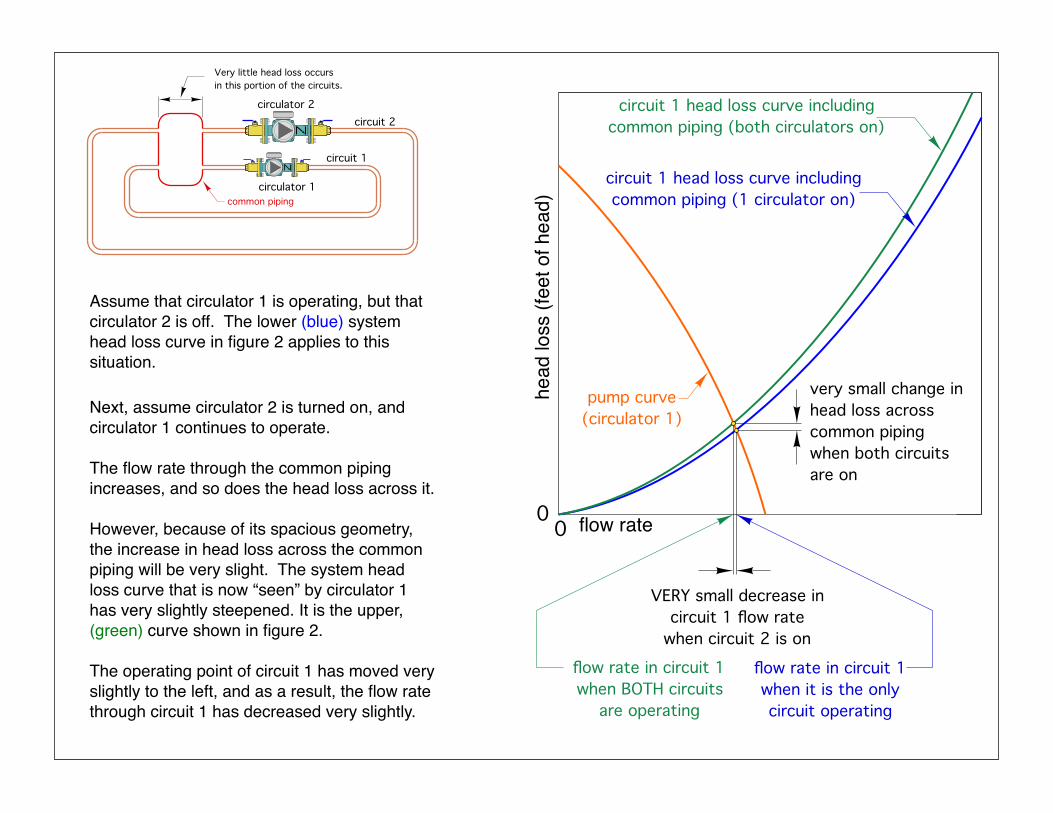
The degree to which two or more operating circulators interact with each other depends on the head loss of the common piping.
The lower the head loss of the common piping the less the circulators will interfere with each other.
common piping
circulator 1
circuit 1
circuit 2 circulator 2
Itʼs the piping components shared by two or more circuits.
When the head loss of the common piping is very low, there is “hydraulic separation” between the circuits.

Very little head loss occurs!in this portion of the circuits.
common piping circulator 1
circuit 1
circuit 2 circulator 2
When the head loss of the common piping is very low, there is “hydraulic separation” between the circuits.
Very little head loss occurs!in this portion of the circuits.
common piping circulator 1
circuit 1
circuit 2 circulator 2
Assume that circulator 1 is operating, but that circulator 2 is off. The lower (blue) system head loss curve in figure 2 applies to this situation.
flow ratehe
ad lo
ss (f
eet o
f hea
d)0
0
pump curve!(circulator 1)
circuit 1 head loss curve including !common piping (both circulators on)
circuit 1 head loss curve including !common piping (1 circulator on)
VERY small decrease in!circuit 1 flow rate!
when circuit 2 is on
very small change in!head loss across!common piping!when both circuits are on
flow rate in circuit 1 when it is the only circuit operating
flow rate in circuit 1 when BOTH circuits!
are operating
Next, assume circulator 2 is turned on, and circulator 1 continues to operate.
The flow rate through the common piping increases, and so does the head loss across it.
However, because of its spacious geometry, the increase in head loss across the common piping will be very slight. The system head loss curve that is now “seen” by circulator 1 has very slightly steepened. It is the upper, (green) curve shown in figure 2.
The operating point of circuit 1 has moved very slightly to the left, and as a result, the flow rate through circuit 1 has decreased very slightly.

Very little head loss occurs!in this portion of the circuits.
common piping circulator 1
circuit 1
circuit 2 circulator 2
Imagine a hypothetical situation in which the head loss across the common piping was zero, even with both circuits operating.
Because NO head loss occurs across the common piping, it would be impossible for either circulator to “influence” the other circulator.
This would be “perfect” hydraulic separation.
Fortunately, perfect hydraulic separation is not required to ensure that the flow rates through independently operated circuits remain reasonably stable.
Almost Perfect Is Good Enough:

The higher the flow resistance of the common piping, the more each circulator will “influence” flow in the other circuit (e.g. the lower the hydraulic separation of the circuits.
common piping (with HIGH FLOW RESISTANCE)
circulator 1
circuit 1
circuit 2 circulator 2
Common piping with high flow resistance is NOT good:

common piping and !heat source have!
HIGH FLOW RESISTANCE
ON ONlarger
circulatorsmaller
circulator
P=22 psibackseated!flow checkP=17psi
common piping and !heat source have!
high flow resistance
large circulator
small circulator
ON
∆P p
rodu
ced"
by c
ircul
ator"
@ 0
flow
= 4
psi
∆P= 5 psi
∆P =
5 p
si
no flow
P=12 psi
P=17 psi
P=13
psi
P=16
psi
ON∆P= 10 psi
High flow resistance common piping - something to avoid
5
10
15
0
head
add
ed (f
eet)
0
6
4
2
02 4 6 8 10
flow rate (gpm)
pump curve!for small circulator
!P=Head
()
D 144
" #$% &'
4 psi ∆P at 0 flow

Multi-zone system - using zone circulators
low flow resistance headers
other zone circuits
low flow resistance heat source
zone circulators with spring-loaded
check valves
purging!valves
OK
other zone circuits
zone circulators with spring-loaded
check valves
purging!valves
compact mod/con
boiler
NOT OK
• Always keep the flow resistance of the “common piping” as low as possible. This provides hydraulic separation between circulators.
• Always provide a check valve on each zone circuit.
high flow resistance of compact boiler creates flow “bottleneck”

circuit 2 circulator 2
common!piping
circulator 1
circuit 1
common!piping
circulator 1
circuit 1
circuit 2 circulator 2
common!piping
Divide & Conquer:Hydraulic separation allows designers to think of an overall system as a collection of independent (“hydraulically isolated) circuits.
From the standpoint of hydraulics, each circuit can be designed as if itʼs a stand-along circuit.
More on this later...

load!#1
load!#2
load!#3
closely!spaced!
tees!(typical)
primary!circulator
secondary!circuit
secondary!circuit
secondary!circuit
secondary circuit
primary!circuit!
(series)
Primary / Secondary piping - where it all began...
Primary / secondary piping, using closely spaced tees, is now well known and often used in North America.
But primary / secondary piping is not the ONLY way to create hydraulic separation...
Primary / secondary piping, is one way to achieve hydraulic separation between circulators.

Both series and parallel primary/secondary systems require a primary circulator.
This adds to the installed cost of the system AND adds hundreds, even thousands of dollars in operating cost over a typical system life.
load!#1
load!#2
load!#3
closely!spaced!
tees!(typical)
primary!circulator
secondary!circuit
secondary!circuit
secondary!circuit
secondary circuit
primary!circuit!
(series)
SERIES primary loop
primary!circulator
closely!spaced!
tees
parallel!primary!circuit
load!#1
load!#2
load!#3
balancing valves
crossover!bridge
PARALLEL primary loop
Series and parallel primary/secondary systems

An example of primary loop circulator operating cost:
Consider a system that supplies 500,000 Btu/hr at design load. Flow in the primary loop is 50 gpm with a corresponding head loss of 15 feet (6.35 psi pressure drop). Assume a wet rotor circulator with wire-to-water efficiency of 25 is used as the primary circulator.
The input wattage to the circulator can be estimated as follows:
W = 0.4344× f ×ΔP0.25
= 0.4344× 50× 6.350.25
= 552watts
Assuming this primary circulator runs for 3000 hours per year its first year operating cost would be:
1st year cost = 3000hryr
⎛
⎝⎜
⎞
⎠⎟
552w1
⎛⎝⎜
⎞⎠⎟
1kwhr1000whr⎛⎝⎜
⎞⎠⎟
$0.10kwhr
⎛⎝⎜
⎞⎠⎟= $165.60

Assuming electrical cost escalates at 4% per year the total operating cost over a 20-year design life is:
This, combined with eliminating the multi-hundred dollar installation cost of the primary circulator obviously results in significant savings.
cT = c1 ×1+ i( )N −1
i
⎛
⎝⎜⎜
⎞
⎠⎟⎟= $165.60×
1+ 0.04( )20 −10.04
⎛
⎝⎜⎜
⎞
⎠⎟⎟= $4,931
An example of primary loop circulator operating cost:

Question: What is the “ideal” header in a hydronic system?Answer: One that splits up the flow without creating head loss
Think about a “copper basketball” with pipes sticking out of it in all directions.
very low head loss!
inside header
Wouldnʼt this be pretty close to an ideal header???

So why donʼt we build headers like this???
very low head loss!
inside header
“Short / fat” headers are GOOD!
Instead, we approximate the ideal header by making it “short” & “fat”
shortfat
Long / skinny headers are BAD!

So whatʼs EXACTLY is a short / fat header???
shortfat
max (design) flow rate
select pipe size that yields a flow velocity no higher than 2 feet per second

very low flow resistance!
common piping!
size headers for max flow velocity of 2 ft/sec
low flow resistance
heat!source
The “short / fat” headers hydraulically separate the distribution circulators from each other.
The low flow resistance heat source maintains low flow resistance of common piping
Hydraulic separation achieved by low flow resistance heat source & “short / fat” headers.

The “short / fat” headers hydraulically separate the distribution circulators from each other.
closely spaced tees
very low flow resistance!common piping!
high flow ! resistance boiler
size headers for max flow velocity of 2 ft/sec
Hydraulic separation achieved by closely spaced tees & “short / fat” headers.
The closely spaced tees hydraulically separate the heat source from the header system.

multiple!boiler!
controller
ouside!sensor
closely!space!tees
zone circulators!(w/ check valves)
air!vent
drain!valve
purge!valves
"short/fat" header
supply !temperature!sensor
A
B
The “short & fat” header and close spacing between supply and return connections results in a low pressure drop between points A and B. Each load circuit is hydraulically separated from the others.
• Header should be sized for max. flow velocity of 2 feet per second
• Each circuit must include a check valve.
• The supply temperature sensor must be downstream of the point of hydraulic separation.
• The header can be vertical (as shown) or horizontal.
Hydraulic separation achieved by closely spaced tees & “short / fat” headers.

The “short / fat” headers hydraulically separate the distribution circulators from each other.
buffer!tank
very low flow resistance!common piping!
size headers for max flow velocity of 2 ft/sec
boiler!circulator
high flow resistance boiler
Hydraulic separation achieved by buffer tank (piped as shown ) & “short / fat” headers.
The buffer tank hydraulically separate the heat source from the header system.

to / from other heating
zones
wood gasification boiler
VENT
ThermoCon tank
Hydraulic separation achieved by buffer tank

earth loop circuits
purging!valves
VENT
temperature!sensor
chilled water
cool
ing
mod
e
reversing!valve
cond
ense
r
evap
orat
or
insu
late
all
chille
d w
ater
pip
ing!
to p
reve
nt c
onde
nsat
ion
chilled water air handlers
ThermoCon tank
zoned chilled water cooling
Only tanks with sprayed foam insulation should be used for chilled water storage.
Hydraulic separation achieved by buffer tank
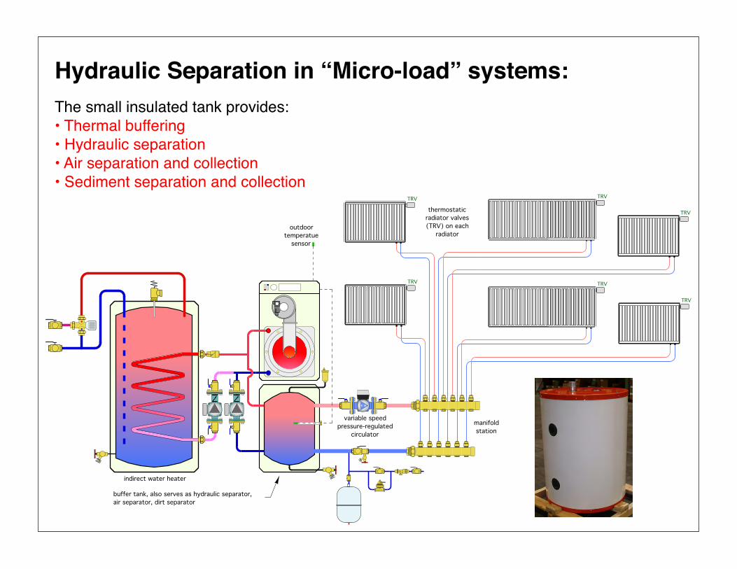
Hydraulic Separation in “Micro-load” systems:The small insulated tank provides:• Thermal buffering• Hydraulic separation• Air separation and collection• Sediment separation and collection
indirect water heater
thermostatic!radiator valves!(TRV) on each!
radiator
TRV
TRV
TRV
TRV
TRV
manifold!station
TRV
variable speed!pressure-regulated!
circulator
outdoor!temperatue!
sensor
buffer tank, also serves as hydraulic separator,!air separator, dirt separator

hydraulic separator
very low flow resistance!common piping!
high flow ! resistance boiler
size headers for max flow velocity of 2 ft/sec
The “short / fat” headers hydraulically separate the distribution circulators from each other.
Hydraulic separation achieved by hydraulic separator.The hydraulic separator hydraulically separates the heat source from the header system.

diam
eter
= 1
"
flow velocity = 4 ft/secdiameter = 3"
flow rate = 6.5 gpm
flow velocity = 0.44 ft/secflow rate = 6.5 gpm
area = A
area = 9Aalmost zero
pressure drop b/w!upper and lower
connections
air bubbles can rise faster than the downward water flow
dirt particle drop into lower bowl
drain valve
air ventWhatʼs going on inside a hydraulic separator?
The low vertical velocity inside the separator produces minimal pressure drop top to bottom. Thus there is very little tendency to induce flow on the load side of the separator.

drain valve
air vent
"STANDARD"!hydraulic !separator
What does the “coalescing media” do inside a hydraulic separator?
The coalescing media creates tiny vortices that cause gas molecules (mostly oxygen and nitrogen) to form microbubbles. The media also helps microbubble merge together and rise upward out of the active flow zone.
upper coalescing media encourages!air bubbles to form
drain valve
air vent
air bubbles "ride" up the vertical filaments of the coalescing media - out of the active flow zone
lower coalescing media encourages!dirt particle to drop!out of active flow zone
HIGH PERFORMANCE!(air & dirt removal)!hydraulic separator
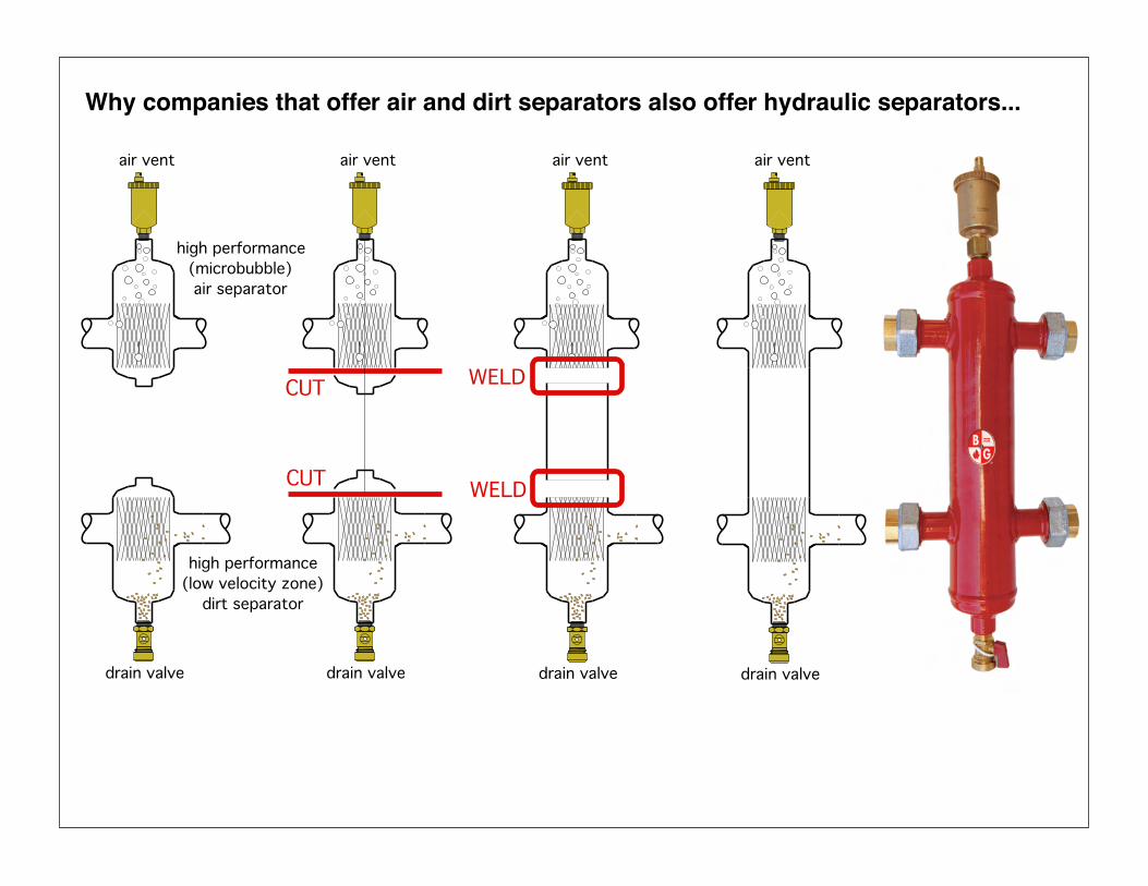
drain valve
air vent
high performance!(low velocity zone)!
dirt separator
high performance!(microbubble)!air separator
drain valve
air vent
WELD
WELD
drain valve
air vent
CUT
CUT
Why companies that offer air and dirt separators also offer hydraulic separators...
drain valve
air vent

heating!load(s)
boiler circuit
distribution system
air!separator
sediment!strainer
closely!spaced!tees
heating!load(s)
boiler circuitdistribution
system
Hydraulic!Separator
High performance hydraulic separators provide three functions:
1. hydraulic separation2. air separation 3. dirt separation

1. Flow in the distribution system is equal to the flow in the boiler circuit.
2. Flow in the distribution system is greater than flow in the boiler circuit.
3. Flow in the distribution system is less than flow in the boiler circuit.
Each case is governed by basic thermodynamic...
As the flow rates of the boiler circuit and distribution system change there are three possible scenarios:

T4T3
T2T1f1 f2
f3 f4
NOTE:
=f1 f3 (always!)
f2 f4=NOTE:
(always!)
In this case only:!
T1 T2T3 T4
==
Case #1: Distribution flow equals boiler flow:
Very little mixing occurs because the flows are balanced.

T4T3
T2T1f1 f2
f3 f4
NOTE:
=f1 f3 (always!)
f2 f4=NOTE:
(always!)
Case #2: Distribution flow is greater than boiler flow:
Mixing occurs within the hydraulic separator.
T2 =f4 − f1( )T4 + f1( )T1
f4
⎛⎝⎜
⎞⎠⎟
The mixed temperature (T2) supplied to the distribution system can be calculated with:
Where:f4 = flow rate returning from distribution system (gpm)f1 = flow rate entering from boiler(s) (gpm)T4 = temperature of fluid returning from distribution system (°F)T1 = temperature of fluid entering from boiler (°F)

Case #3: Distribution flow is less than boiler flow:
T2 =f4 − f1( )T4 + f1( )T1
f4
⎛⎝⎜
⎞⎠⎟
The temperature returning to the boiler (T3) can be calculated with:
Where:T3 = temperature of fluid returned to boiler(s) (°F)f1 = flow rate entering from boiler(s) (gpm)f2, f4 = flow rate of distribution system (gpm)T1 = temperature of fluid entering from boiler (°F)T4 = temperature of fluid returning from distribution system (°F)
Heat output is temporarily higher than current system load.
Heat is being injected faster than the load is removing heat.
T4T3
T2T1
f1 f2
f3 f4
NOTE:
=f1 f3 (always!)
f2 f4=NOTE:
(always!)
Mixing occurs within the hydraulic separator.

Sizing of Hydraulic Separators:
Hydraulic separators must be properly sized to provide proper hydraulic, air, and dirt separation. Excessively high flow rates will impede these functions.
The piping connecting to the distribution side of the Hydro Separator should be sized for a flow of 4 feet per second or less under maximum flow rate conditions.
The “size” of a hydraulic separator refers to the nominal piping size of the 4 side connections (not the diameter of the vertical barrel).
Pipe sizeof
hydraulicseparator
1” 1.25” 1.5” 2” 2.5” 3” 4” 6”
Max flowrate
(GPM)11 18 26 40 80 124 247 485
union connections
flange connections

Typical European concepts for multiple mod/con installation:

Typical European concepts for multiple mod/con installation:
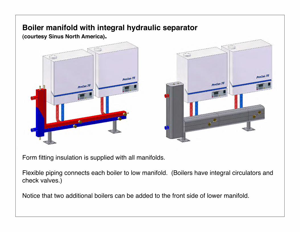
Boiler manifold with integral hydraulic separator (courtesy Sinus North America).
Form fitting insulation is supplied with all manifolds.
Flexible piping connects each boiler to low manifold. (Boilers have integral circulators and check valves.)
Notice that two additional boilers can be added to the front side of lower manifold.

Here's what the real products look like…

How about 8 mod/cons with integral hydraulic separator… (courtesy Sinus North America).
Think of the output per unit of mechanical room floor area…
Each boiler can be independently serviced .
Flexible piping connects each boiler to low manifold. (Boilers have integral circulators and check valves.)

Example of Hydro Separator Installation in New System:Magna Steel Corporation - Connecticut
Photos courtesy of Peter Gasperini - Northeast Radiant

Example of Hydro Separator Installation in Old System:
Because hydraulic separators remove sediment fromsystems they’re ideal for applications where new boilers are retrofit to old distribution systems.

Example of Hydro Separator Installation in Old System:Because hydraulic separators remove sediment from systems theyʼre ideal for applications where new boilers are retrofit to old distribution systems.
hydraulic!separator
supply!temp.!sensor
from existing system
sediment capture!and removal
multiple!boiler!
controller outdoor!temperature!
sensor

existing cast-iron radiators (converted from steam)
existing piping
mod/con boiler!w/ compact heat exchanger
supply!temperature!
sensor
ECM!pressure!regulated!circulator
vent
hydraulic!separator
A hydraulic separator is a great way to interface a new mod/con boiler to a older “steam conversion” system.
WHY?
Dirt separation is especially important in older systems with iron components.

fluid feeder
earth loop circuits
purging!valves
purge
variable-speed!pressure-regulated!
circulator
geothermal manifolds
hydro!separator
to / from!other heat pumps
heat
ing
mod
e
reversing!valve
cond
ense
r
evap
orat
or
water-to-water!heat pump
zone!valve
balancing!valve
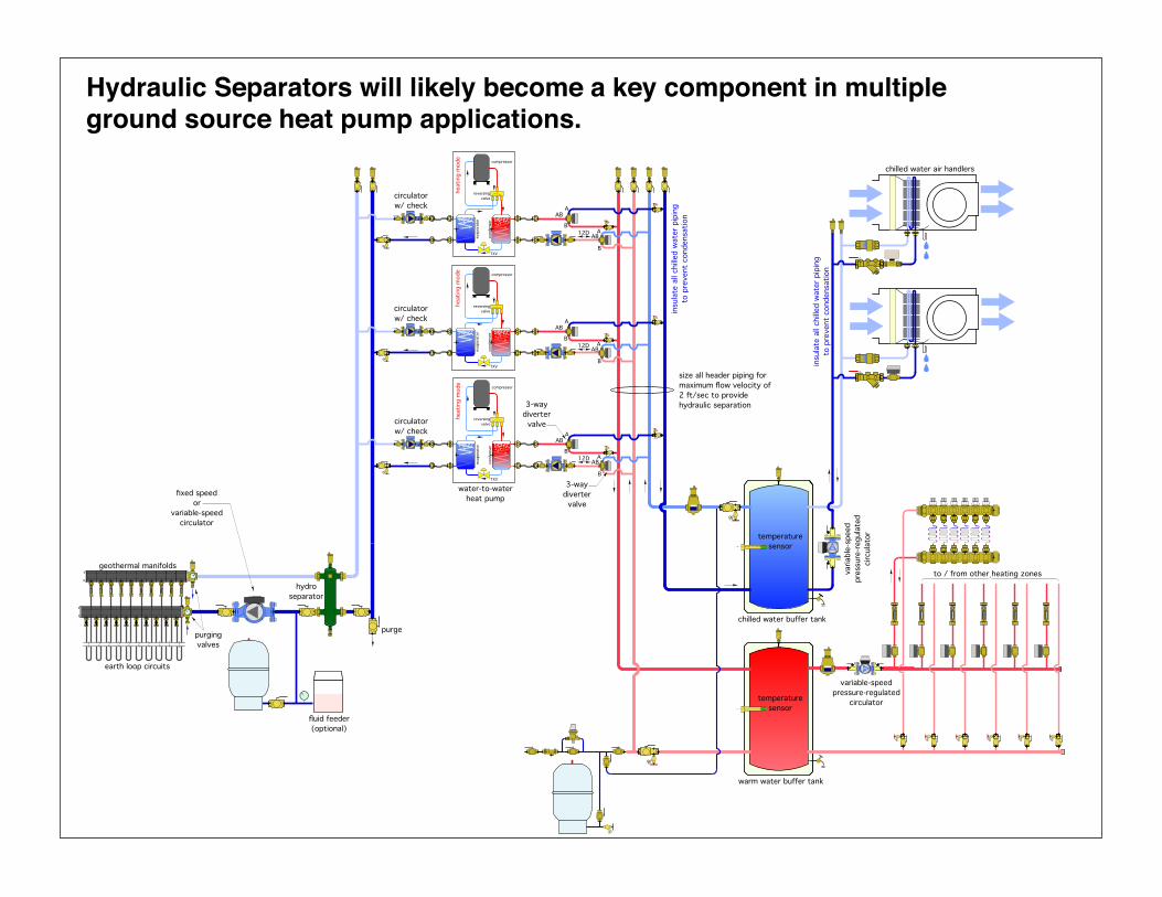
Hydraulic Separators will likely become a key component in multiple ground source heat pump applications.
The will allow the flow rate in the earth loop to be different than the flow rate through the heat pump array - more on this later...
temperature!sensor
VENT
fluid feeder!(optional)
earth loop circuits
purging!valves
purge
to / from other heating zones
variable-speed!pressure-regulated!
circulator
geothermal manifolds
hydro!separator
water-to-water!heat pump
chilled water buffer tank
temperature!sensor
warm water buffer tank
circulator!w/ check
3-way!diverter!
valve
insu
late
all
chille
d w
ater
pip
ing!
to p
reve
nt c
onde
nsat
ion
chilled water air handlers
varia
ble-
spee
d!pr
essu
re-r
egul
ated
!ci
rcul
ator
insu
late
all
chille
d w
ater
pip
ing!
to p
reve
nt c
onde
nsat
ion
reversing!valve
cond
ense
r
evap
orat
or
compressor
TXV
heat
ing
mod
e
size all header piping for maximum flow velocity of 2 ft/sec to provide hydraulic separation
fixed speed!or!
variable-speed!circulator
12D AAB
B
AAB
B
circulator!w/ check
reversing!valve
cond
ense
r
evap
orat
or
compressor
TXV
heat
ing
mod
e
12D AAB
B
AAB
B
circulator!w/ check
reversing!valve
cond
ense
r
evap
orat
or
compressor
TXV
heat
ing
mod
e
12D AAB
B
AAB
B
3-way!diverter!
valve
Hydraulic Separators will likely become a key component in multiple ground source heat pump applications.

circuit 2 circulator 2
common!piping
circulator 1
circuit 1
common!piping
circulator 1
circuit 1
circuit 2 circulator 2
common!piping
Divide & Conquer:Hydraulic separation allows designers to think of an overall system as a collection of independent (“hydraulically isolated) circuits.
From the standpoint of hydraulics, each circuit can be designed as if itʼs a stand-along circuit.

• Simplifying system analysis• Preventing flow interference
Divide & Conquer:
LWCO
cast-iron sectional boiler!with oil burner
brass unions!(typical)
PRV
closely spaced tees
3/4"
cop
per
Webstone!purging!valves
variable speed!pressure regulated!
circulator!set for ∆Pc
!mix supply!sensor
1.25" copper 12D
3/4"
cop
per
1" c
oppe
r
3/4"
cop
per
3/4"
cop
per
1" c
oppe
r
3/4"
cop
per
3/4"
cop
per
3/4"
cop
per
outdoor!sensor
TRV
TRV
TRV
TRV
TRV
TRV
thermostatic radiator valves!on each panel radiator
12- circuit manifold distribution system
using PEX or PEX-AL-PEX tubing
panel radiator
MRH
L
12D
356 injection mixing controller
closely spaced tees3/4"
cop
per
balancing!valve
outdoor!sensor
purging!valves
1" c
oppe
r
!mix supply!sensor
1" c
oppe
r
1" c
oppe
r
1" c
oppe
r
1.25" copper 12D
manifold B
manifold A
2" copper supply!and return headers!
keep as short as possible
2" copper
2" copper
1.25" copper
3/4" copper
12D
1" copper
12D 12D
3/4"
cop
per
return temperature!sensor for 356!
mixing controllers
!indirect water heater
12D
2" air separator3/4" fast fill piping
3/4" cold water supply
12D
manifold G!(garage)
strap-on!aquastat!contacts!
close at 100ºF!open at 50ºF
P1
P2
P3
P4
P5
P6
P7
P8These panel radiators are representative!of second floor heating distribution system!exact size and number of panels may vary,!but all are supplied with 1/2" PEX-AL-PEX tubing, and controlled by individual thermstatic radiator valves.
30 psi!PRV
fill/purgesupply sensor
3/4"
cop
per
12DHW
CW
P&TRV
tank acqustat
floor!drain
1.25" copper
swing!check
manifold C
manifold D
manifold E
manifold F
!brazed plate SS!heat exchanger
to / from other!radiators
This portion of system filled with 40% solution of inhibited
propylene glycol
3/4"
cop
per
3/4" copper
manifold H (2nd floor)
manifold I (2nd floor)3/
4" c
oppe
r
3/4"
cop
per
3/4"
cop
per
variable speed!pressure regulated!
circulator!set for ∆Pc
356 injection mixing controller
356 injection mixing controller
balancing!valve
zone valves
all three injection pumps!equipped with internal!
check valves
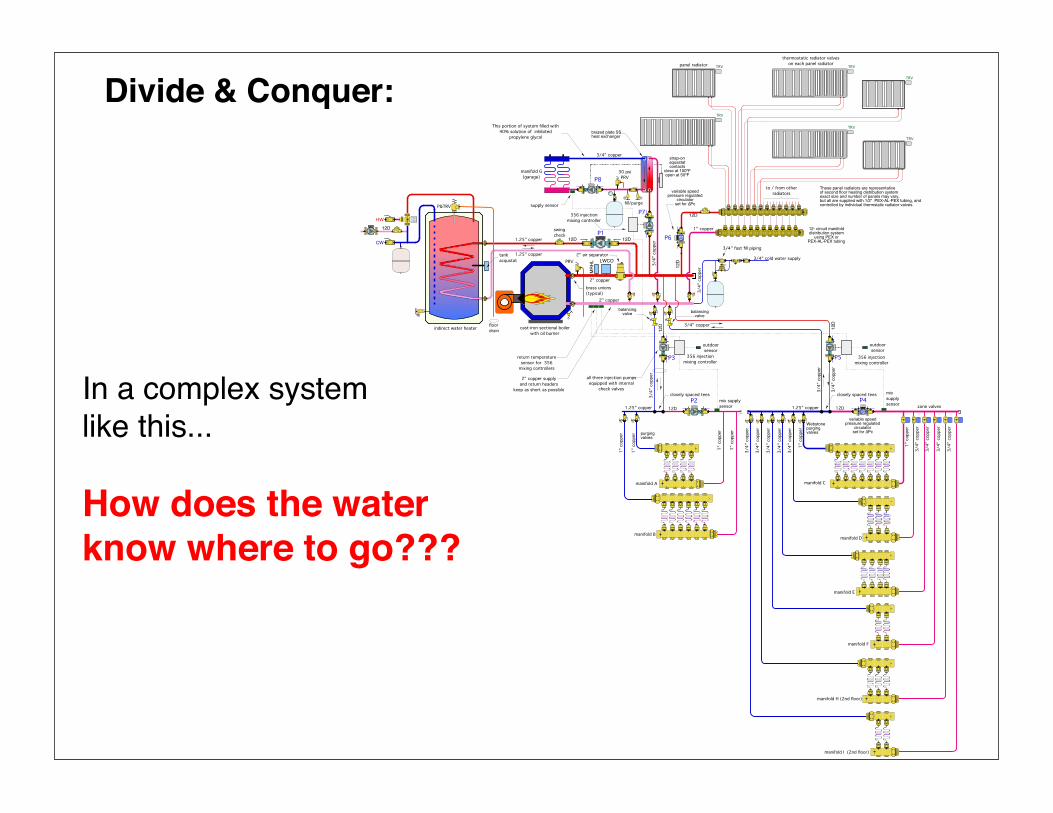
Divide & Conquer:
In a complex system like this...
How does the water know where to go???
P1
cast-iron sectional boiler
P2
P3
P4
P5
manifold H (2nd floor)
manifold I (2nd floor)
P7
P8
TRV
TRV
TRV
TRV
TRV
TRV
P6
low flow resistance heat source!+ short / fat headers
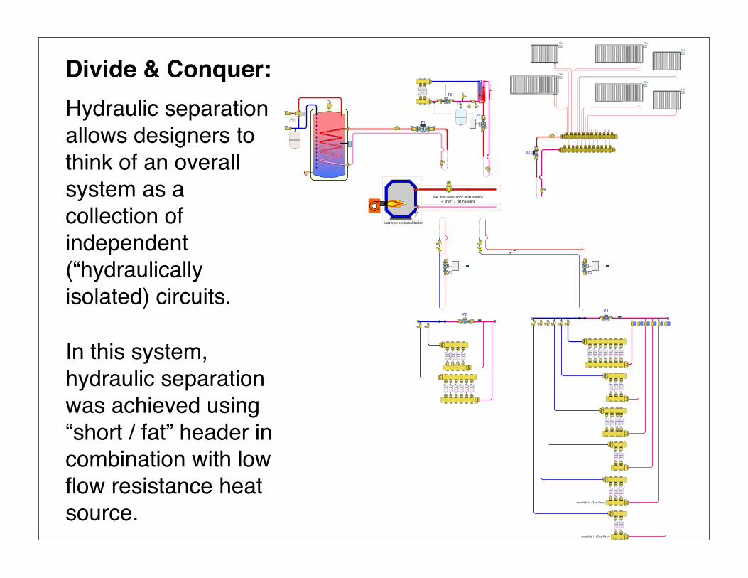
In this system, hydraulic separation was achieved using “short / fat” header in combination with low flow resistance heat source.
Hydraulic separation allows designers to think of an overall system as a collection of independent (“hydraulically isolated) circuits.
Divide & Conquer:

You find it: Where is the hydraulic separation in this system?
reversing!valve
cond
ense
r
evap
orat
or
TXV
cool
ing
mod
e
VENT
temperature!sensor
insu
late
all
chille
d w
ater
pip
ing!
to p
reve
nt c
onde
nsat
ion
chilled water air handlers
to / from other heating
zones
buffer tank
heating is off
chilled water
variable-speed!pressure-regulated!
circulator
electric!heating!element
DHW P&TRV
water heater
geothermal manifolds
earth loop circuits
purging!valves

You find it: Where is the hydraulic separation in this system?
closely!spaced!
tees
air handler w/ drip pan
indoor unit
INSI
DE
OUTS
IDE
!outdoor unit
thermostatic tempering valve
indiret water heater with auxiliary electric element
motorized diverter
valve
make-up!water &
supllemental!expansion
tank
variable speed!pressure regulated!
circulators
purge!valve
flow setterzone valve
low flow resistance headers
chilled water cooling
low temperature space heating

Hydraulic Separators now available in North America
Sinus North AmericaPrecision Hydronic
Products
Bell & Gossett
Taco
SpirothermCaleffi

Thank you for attending...
www.hydronicpros.com
Please visit our website for more information (publications & software) on hydronic systems:


![DBD plasma microbubble reactor for pre-treatment of … · DBD plasma microbubble reactor for pre-treatment of lignocellulosic biomass [poster] ... DBD plasma microbubble reactor](https://static.fdocuments.in/doc/165x107/5e4523a0e85b14090f08d100/dbd-plasma-microbubble-reactor-for-pre-treatment-of-dbd-plasma-microbubble-reactor.jpg)