Phazotron Zhuk AE/ASE - thz-historia.de · Phazotron Zhuk AE/ASE ... A Radar Engineering...
23
Last Updated: Mon Jan 27 11:18:09 UTC 2014 Phazotron Zhuk AE/ASE Assessing Russia's First Fighter AESA Technical Report APA-TR-2008-0403 by Dr Carlo Kopp, AFAIAA, SMIEEE, PEng 19th July, 2008 Updated April, 2012 © 2008 Carlo Kopp The MiG-35 Zhuk AE AESA designed by Phazotron is the first Russian AESA design and is expected to spawn upgrade packages for Flanker variants, as Phazotron have been trying for over ten years to break NIIP's defacto converted by Web2PDFConvert.com
Transcript of Phazotron Zhuk AE/ASE - thz-historia.de · Phazotron Zhuk AE/ASE ... A Radar Engineering...

Last Updated: Mon Jan 27 11:18:09 UTC 2014
Phazotron Zhuk AE/ASEAssessing Russia's First Fighter AESA
Technical Report APA-TR-2008-0403
by Dr Carlo Kopp, AFAIAA, SMIEEE, PEng 19th July, 2008
Updated April, 2012© 2008 Carlo Kopp
The MiG-35 Zhuk AE AESA designed by Phazotron is the first Russian AESA design and is expected to spawnupgrade packages for Flanker variants, as Phazotron have been trying for over ten years to break NIIP's defacto
converted by Web2PDFConvert.com

monopoly on volume production Flanker radars (MiGAvia.ru).
Abstract
T he Zhuk AE developed for the MiG-35 and legacy MiG-29 upgrades isthe first Russian Active Electronically Steered Array (AESA [Click for more...]) antenna equipped radar to be disclosed publicly. T he manufacturer,N I I R Phazotron, has released a considerable volume of technicalliterature detailing the design philosophy and technology employed inthis radar. T his paper explores, in radar engineering terms, antenna andtransmit receive channel related design features, and the cardinalperformance parameters for this radar. While this pre-production radaroperates at the lower end of the X-band and has a lower transmitreceive channel count than Western radars of similar aperture size, itdelivers power-aperture performance superior to all but the very latestWestern small aperture fighter radars. T he Zhuk AE employs lowerdensity liquid cooled quad channel transmit receive module packagingtechnology which is comparable to first generation US AESA designs.
A parametric analysis and power aperture modelling is performed on theproposed Zhuk ASE, which is a scaled up version of the Zhuk AEfollowing the model of the Zhuk MSFE built for the Flanker. T he Flankersized Zhuk ASE radar with existing Russian transmit receive moduletechnology will deliver around 60 percent higher raw power apertureperformance compared to US APG-79 (F/A-18E/F BI I ) and APG-81 (JSF)class radars, and if fitted with transistor technology permitting 15Watts/channel or more, as proposed by NI I R Phazotron, it w illoutperform the N035 I rbis-E (Su-35BM) and all currently deployed USfighter radars other than the APG-77(V)2 (F-22A Raptor). T he earliestfeasible IOC for the Zhuk ASE on the Flanker is estimated at 2010.
Background and Zhuk Development HistoryZhuk AE Design Philosophy - A Radar Engineering Perspective
Zhuk AE AESA Specifications and Cardinal Design ParametersZhuk ASE AESA - Scaling the Zhuk AE for the FlankerAcknowledgmentsReferencesBibliographyEndnotes
Background and Zhuk Development History
Russia's radar industry has survived the post Cold War trauma of collapsing budgets and hassince then strongly reoriented towards export markets. O f the three most prominent radarhouses, Tikhomirov NIIP, Phazotron NIIR and Leninetz, Tikhomirov NIIP has enjoyed thelargest export sales volumes and earnings mostly by virtue of its entrenched position assupplier of Flanker radars. Phazotron on the other hand has carved out a niche as thetechnological innovators in the Russian industry.
Phazotron has a long history as one of the leading Soviet era radar design bureaus, andwere the primary designers of the N019 Topaz / Slot Back series of pulse Doppler radars forthe MiG-29 Fulcrum fighter. The Zhuk family of radars, which has largely occupiedPhazotron's designers since the end of the Cold War, are an evolutionary offshoot of theN019 family.
The first of the Zhuk (Beetle) radars was developed for the stillborn mid 1980s MiG-29M/MiG-33 Fulcrum upgrade and production effort. Designated the N010 Zhuk, this was arelatively modern pulse Doppler design modelled on the US APG-65 and APG-68 radars,using a slotted planar array antenna with a 0.68 metre diameter aperture, with an average
converted by Web2PDFConvert.com
power rating of 1 kW and peak rating of 5 kW. W ith the end of the Cold War andPhazotron's emergence as an independent entity in an open market, the effort invested intothe Zhuk was exploited to develop a family of radars designed for the MiG-29, Su-27/30 andolder Soviet era fighters as upgrades.
The Zhuk-27 was a variant of the baseline N010 but fitted with a much larger 0.98 metrediameter slotted planar array antenna, and possibly an uprated TW T, intended for the Su-27SK Flanker B. Its contemporary was the Zhuk-8P developed for the PLA-AF J-8-II Finback,with a smaller antenna and thus lower range performance. Importantly this period also sawthe development of the Zhuk-F, a passive ESA (PESA) or phased array with a 0.98 mdiameter aperture. The Zhuk-F evolved further into the Sokol, which is the basis of thecurrent Zhuk-MSF/MSFE PESA variants for the Flanker. The PESA variants of the Zhukcompare most closely to variants of the N011M BARS, but use a fixed PESA aperture ratherthan NIIP 's gimballed design. The nearest Western technological equivalent is the FrenchRBE2 PESA radar in the Rafale.
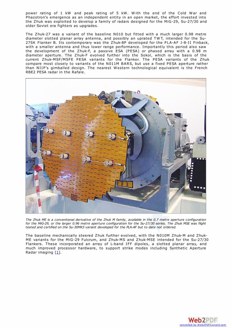
The Zhuk ME is a conventional derivative of the Zhuk M family, available in the 0.7 metre aperture configurationfor the MiG-29, or the larger 0.96 metre aperture configuration for the Su-27/30 series. The Zhuk MSE was flighttested and certified on the Su-30MK3 variant developed for the PLA-AF but to date not ordered.
The baseline mechanically steered Zhuk further evolved, with the N010M Zhuk-M and Zhuk-ME variants for the MiG-29 Fulcrum, and Zhuk-MS and Zhuk-MSE intended for the Su-27/30Flankers. These incorporated an array of L-band IFF dipoles, a slotted planar array, andmuch improved processor hardware, to support strike modes including Synthetic ApertureRadar imaging [1].
converted by Web2PDFConvert.com
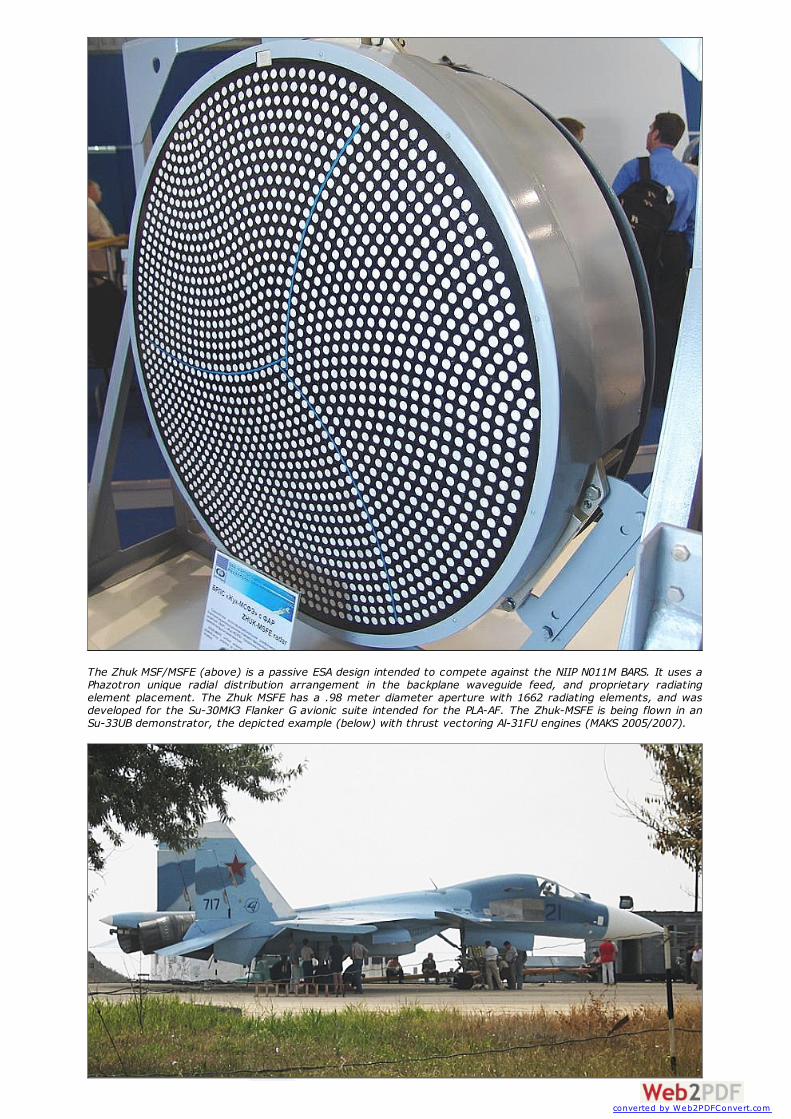
The Zhuk MSF/MSFE (above) is a passive ESA design intended to compete against the NIIP N011M BARS. It uses aPhazotron unique radial distribution arrangement in the backplane waveguide feed, and proprietary radiatingelement placement. The Zhuk MSFE has a .98 meter diameter aperture with 1662 radiating elements, and wasdeveloped for the Su-30MK3 Flanker G avionic suite intended for the PLA-AF. The Zhuk-MSFE is being flown in anSu-33UB demonstrator, the depicted example (below) with thrust vectoring Al-31FU engines (MAKS 2005/2007).
converted by Web2PDFConvert.com

The most advanced of the Phazotron Flanker radars is the Zhuk-MSFE PESA variant, currentlybeing flight tested on the Su-27KUB/Su-33UB side-by-side cockpit navalised Flanker variant,likely to be acquired by the PLA-N as part of their intended carrier airwing for the VaryagCVA. This radar is usually credited with a 2 KW average power rating and 8 kW peak powerrating, putting it in the performance class of the NIIP N011 MSA radar on the Su-27K/Su-35Flanker E. The PESA design has 1662 radiating elements.
Phazotron Slotted Planar ArraysDiameter [m] Gain
[dB]Mainlobe -3 dB[deg]
First Sidelobe[dB]
Bandwidth[%]
Ave Power Handling[kW]
Weight[kg]
0.35 29.0 6.8 -12 2 0.24 1.4
0.47 31.0 4.8 -25 2 0.2 2.2
0.5 31.0 4.7 -22.5 2.4 1.6 2.3
0.624 33.8 3.4 -21 1.6 3.8
0.98 36 2.3 -22 2.4 1.5 7.9
Phazotron Passive Phased Arrays0.44 - Kopyo ~31.0 4.8 - - 0.3 -
0.6 - Zhuk-FGM-29
~34.0 3.4 - - 1.6 -
0.98 - Zhuk-MSFE
37.0 2.3 -30.0 - 3.0 -
The Zhuk-AE AESA [Click for more ...] is an offspring of the Zhuk-MF/MFE variant, a 0.7 mdiameter aperture PESA derivative of the N010M Zhuk-M and Zhuk-ME variants, and wasdeveloped for the MiG-35 Fulcrum being bid for India's MRCA requirement to replace initially128 of around 400 legacy Russian fighters.
The potentially large size of the Indian order has seen Western and Russian bidders discloseremarkably large amounts of data on their products, and Phazotron produced a special issueof their house journal Phazotron, which contains some very good technical papers byPhazotron engineers detailing the internals of the Zhuk-AE and its underlying designphilosophy. This is the single biggest technical disclosure on any AESA design, globally, todate. This APA analysis is largely based upon this document, but also exploits other opensource materials.
The strategic importance of the Zhuk AE cannot be understated. Russian industry hascrossed the key hurdles of designing and integrating viable GaAs MMICs and performing theoverall integration and design of an AESA. From this point we will see increasingly convergence with Western technology for AESAs, as new technologies like Gallium NitrideHEMT transistors are incorporated, and US style tiled packaging technology emulated. Therate of advancement will be mostly limited by the scale of investment into development.
This analysis looks closely at the technology of the Zhuk AE and its design philosophy, inmore technical depth than previous APA technical reports, and explores the implications ofPhazotron's stated intent to scale the design up for the Flanker.
converted by Web2PDFConvert.com
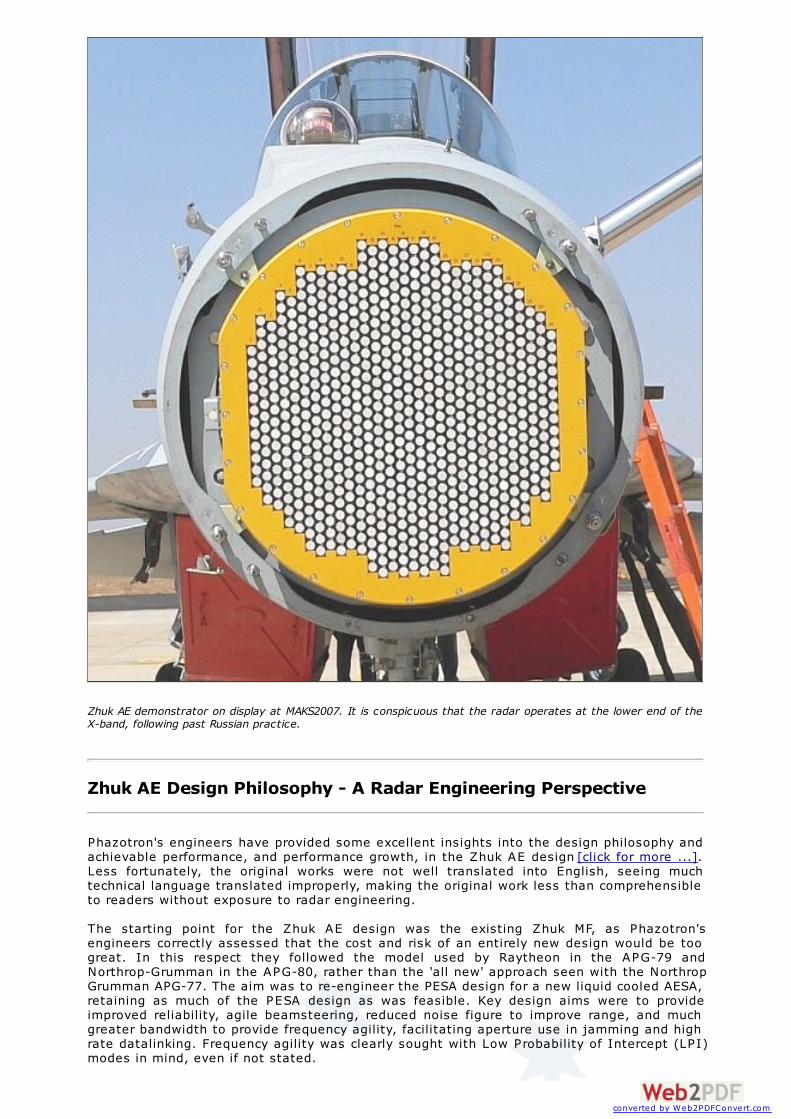
Zhuk AE demonstrator on display at MAKS2007. It is conspicuous that the radar operates at the lower end of theX-band, following past Russian practice.
Zhuk AE Design Philosophy - A Radar Engineering Perspective
Phazotron's engineers have provided some excellent insights into the design philosophy andachievable performance, and performance growth, in the Zhuk AE design [click for more ...].Less fortunately, the original works were not well translated into English, seeing muchtechnical language translated improperly, making the original work less than comprehensibleto readers without exposure to radar engineering.
The starting point for the Zhuk AE design was the existing Zhuk MF, as Phazotron'sengineers correctly assessed that the cost and risk of an entirely new design would be toogreat. In this respect they followed the model used by Raytheon in the APG-79 andNorthrop-Grumman in the APG-80, rather than the 'all new' approach seen with the NorthropGrumman APG-77. The aim was to re-engineer the PESA design for a new liquid cooled AESA,retaining as much of the PESA design as was feasible. Key design aims were to provideimproved reliability, agile beamsteering, reduced noise figure to improve range, and muchgreater bandwidth to provide frequency agility, facilitating aperture use in jamming and highrate datalinking. Frequency agility was clearly sought with Low Probability of Intercept (LP I)modes in mind, even if not stated.
converted by Web2PDFConvert.com

Phazotron contracted NPF Mikran at Tomsk, a semiconductor manufacturer, with support fromthe Tomsk Electronics University, to develop the Gallium Arsenide MMIC (MonolithicMicrowave Integrated Circuits) technology for the radar's critical TR Modules.
The new radar would use a new antenna and Analogue/Digital Converter (ADC) design, anew exciter/driver stage, but retain the existing receiver chain, processors, and coherentoscillator. Intended improvements for a production design include better processing and abroadband programmable master oscillator module. The latter is to provide many of theadvanced capabilities seen in the latest Western AESAs.
Phazotron summarise the key design components as:
Antenna face with radiator elements.TR channel electronics, each connected to a radiator element.Cold plate liquid cooling system.Array power supply.Control logic for each TR channel.RF feed for the array.Secondary power supplies.Beam control processor to generate beamsteering commands.
Design teams were formed to cover every specific aspect of the design, including aperturedesign, radiating element design, TR channel circuit design, TR channel MMIC and controllogic EPLD design, TR channel and module layout, TR module thermal management, thermalefficiency and secondary supply design, TR module control design, TR module secondarypower supply design, RF feed design from the master/oscillator and excite stage.
The design aim was to build an X-band array with a maximum beamsteering angle of 70°,without any unwanted sidelobes arising. This is the basic problem in all AESA designs,insofar as grating lobes require element spacing of less than one half of a wavelength, whilethe resulting packing density presents heat transfer problems.
The power rating and PAE (Power Added Efficiency) of the driver transistor was consideredanother issue, with initial estimation at 6 to 8 Watts CW (12 to 16 Watts peak at 50% dutycycle). The small size of the aircraft and its limited power and cooling capacity were seen tobe serious constraints. The drive transistors are operated in A-class to provide best possiblelinearity, with a performance penalty in a design with an overall PAE of 22% to 25%. C-classoperation was rejected due to its adverse impact on signal purity.
Phazotron have stated, not surprisingly, that the biggest difficulties were encountered inengineering the TR modules. The approach taken after evaluating dozens of alternatives wasto integrate four TR channels into a single "quad" module, as this was found to be the mostpractical tradeoff. An interesting observation is that this is a scheme identical to that usedfor first generation AESAs by US designers in the late 1980s, followed by the TR "stickmodule" scheme used in early US production AESAs.
Thermal management proved to be the single most difficult problem, and Phazotron claim tohave finally produced a design with very high heat transfer efficiency.
The intent of the production Zhuk AE configuration is to provide a package which allowsdirect upgrades of legacy Fulcrum radars in existing aircraft, as well as provide radars fornew production aircraft.
Phazotron's objectives for the production phase of the Zhuk AE lifecycle include fullautomation of AESA component testing, signal simulators to permit more extensive testingof operating modes and performance, better firmware and software for the radar's processingcomponents, more effective algorithms for signal processing and beam control, and astatistical database for managing reliability over the lifecycle of the equipment.
Extensive design tradeoff studies were performed, covering power aperture and rangeperformance vs thermal load performance for average TR module power ratings from 1 Wattto 15 Watts. A major issue was beamsteering to 70° as issues arose with sidelobes andprojected aperture area beyond 60° of beamsteering angle.
An idea explored and rejected was the use of simultaneous multiple mainlobes, as thispresented a range of unwanted difficulties.
Phazotron appear to be exploring digital beamforming techniques in what Chief DesignerDolgachev describes as a two stage processing scheme, with initial beamforming performedin the AESA, and additional beamforming in the digital receiver, downstream of the ADCstage. Adaptive nulling of mainlobe jammers is also raised as a benefit of the AESA design.
converted by Web2PDFConvert.com

Dolgachev also observed that a key factor in the design process was maintaining a focus onkey performance parameters, and exploiting computational simulations extensivelythroughout the design process.
The starting point for the AESA design was the development of a complete computationalsimulation for the design, the aim of which was to explore various design tradeoffs to findthose which worked best. Single channel TR modules were rejected in favour a morethermally efficient 4 channel quad module design. The proprietary diamond lattice placementof radiating elements used in earlier PESAs was rejected as it presented difficulties insplitting the array cleanly into the multiple phase centres required for monopulse angletracking, nevertheless the stagger in the elements still provides a robust diamond latticepattern. The resulting module configuration is designed to carry RF signals along theshortest geometrical path between the array face and the feed, with coolant flow transverse(normal) to the antenna boresight.
The result of these tradeoff studies resulted in the final placement of the radiating elementsin vertical columns, each comprising an integer multiple of four elements to accommodatethe TR module structure. Performance achieved for the final element placement was a firstsidelobe at -30 dB, an average of higher order sidelobes at -50 dB, mainlobe widthdegradation of 4 dB at maximum beamsteering angle, and no grating lobes within thesought beamsteering angular range.
Computational simulations were performed to determine the appropriate quantisationincrements for antenna TR channel phase and gain control. Five bits were found to beadequate for amplitude, and six bits for phase control. Each TR channel in the array isindividually addressed on the control bus.
The backplane feed uses an undisclosed radial waveguide design, rather than thesegmented linear branched feeds seen in first generation Western AESAs and ESAs. Anetwork of coaxial waveguide switches between the feed network and TR modules is used tomanage phase centres and perform monopulse summing and differencing for angle trackmodes.
Power supply distribution to the TR modules presented similar problems with module'pulling' during current drain transients, and was accommodated by the pragmatic expedientof attaching a large charge store capacitor on the main power bus near each of the TRmodules.
Cooling was arranged by mounting each TR module on an integral frame cold plate, thelatter being actively cooled by liquid flow. Heat is transferred from each MMIC or transistorinto the base of the module, and then into the cold plate for removal. Phazotron have notdisclosed the thickness of the cold plates or TR modules, but clearly the horizontal elementpitch is the hard constraint here. Each TR module includes an embedded thermal sensorwhich forces a module shutdown if overheating occurs, and restart cannot occur until themodule cools down. All modules are thermally compensated in amplitude and phase toensure that the performance characteristics remain aligned regardless of temperature andoperating frequency.
Dolgachev describes the current TR module parameters as such:
Average power of 5 WattsTransmit path gain of 34 dBReceive path gain of 30 dBReceiver noise figure of 2.5 dB [2]Phase shifter control increments of 5.625°Amplitude control increments of 0.7 dBDynamic range for amplitude control of 24 dBOverall PAE of 25%
Modules and channels are independently addressed, evidently with two low order bitsreserved for the channel, and the remaining eight high order bits for module addressing.
An exciter preamplifier stage was developed to boost the output from the master oscillatormodule to compensate insertion loss from injection into the antenna feed backplane. Theliquid cooled amplifier module has four ganged amplifier chains with a peak power outputsaid to be 20 Watts.
An automated arrangement was set up to test amplitude/phase performance of the TRmodules, to permit calibration and compensation of errors to meet the required 3° errorbound. Further automated equipment needed to be developed to measure and calibrate thefully assembled array, since the average power output of around 3 kW presented a hazard topersonnel. A test rig using a power sensor aligned with the antenna boresight was used,
converted by Web2PDFConvert.com

with each module driven separately (with all others shut down) to measure the installedphase and amplitude performance. Measurements were then processed in software todetermine overall antenna performance.
Phazotron believe that the existing Zhuk AE design is performing below its potential, sincemuch of the processing it uses was taken unchanged from earlier mechanically steeredarrays and is thus not optimised to exploit the AESA.
A separate paper by Semyonov et al discusses in some detail the design of GaAs MMICsused in the gain control, driver and phase shifter blocks of the TR channel. These werepackaged together in single 8 x 22.5 x 2.5 mm sized hybrid with a heat transfer optimisedmetal case.
The 5-bit digitally controlled attenuator is a GaAs MMIC die which uses 50 Ohm/sq resistivefilm for resistor components. The active components are Schottky transistors. High order bitstages are implemented in two 8 dB stages, for a total of 16 dB of controlled loss. The loworder bit control stages are implemented as 1 dB stages. The total insertion loss of thecontrolled attenuator is 8 - 10 dB, with an RMS error of 0.5 dB between 4 and 11 GHz, andtotal attenuator bandwidth of 4 to 14 GHz.
The 6-bit phase shifter function was split between two GaAs MMIC dies. Phazotron havestated that the shifters were intentionally built using a folded directional coupler designrather than switched filters. The four higher order bits, covering 180.0°, 90.0°, 45.0° and22.5° shifts are implemented on one die, the two low order bits for 11.25° and 5.625° shiftson a second smaller die. This approach was chosen to bypass problems with device yield inproduction. It is intended that the 4-bit shifter be further improved to decrease thesensitivity of the 180.0° stage to production variations, and to reduce the per stageinsertion loss from 2.5 dB to 1.5 dB. The design has been proven to perform between 8 and11 GHz with an RMS phase error of around 6°, i.e. one bit. To compensate for the insertionloss of the attenuator and phase shifter stages, an additional buffer amplified was includedin the hybrid design. This GaAs MMIC design provide 7 to 9 dB of gain between 8 and 11GHz.
According to Phazotron, the performance of the hybrids proved initially below expectations,with excessive phase and attenuation errors, due to problems with the alignment of thewires used to connect the dies to the package pins, assessed to be an inherent problem ofthe packaging used. The intent is to move to LTCC (Low Temperature Cofired Ceramic) andMCM-D (Multi Chip Module - Deposited) technology to get high production yields. Inprototype modules, most of the gain and phase errors were actively compensated by controlinputs to the array.
Phazotron envisage the Zhuk AE as a new production radar, as well as an upgrade packagefor legacy MiG-29 Fulcrum fleets. A scaled up variant for the Flanker is also envisaged.
converted by Web2PDFConvert.com
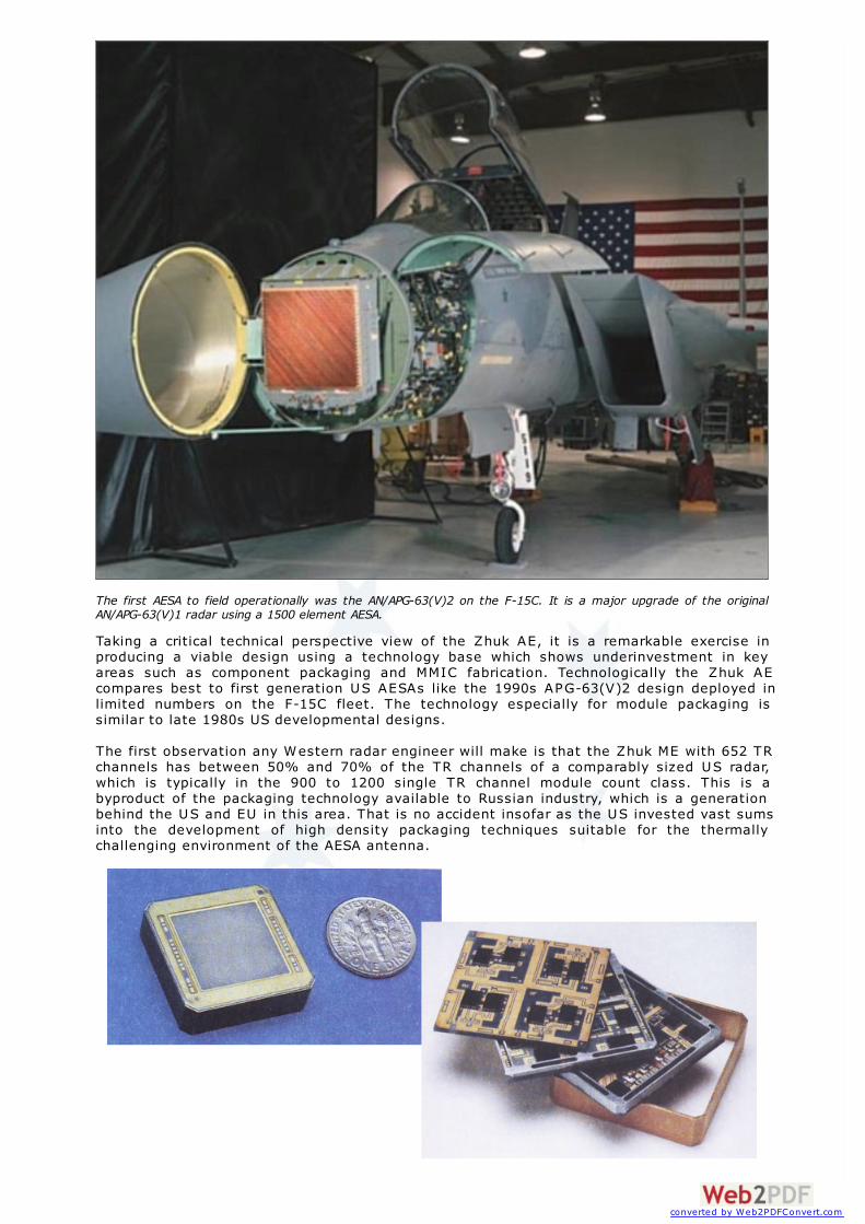
The first AESA to field operationally was the AN/APG-63(V)2 on the F-15C. It is a major upgrade of the originalAN/APG-63(V)1 radar using a 1500 element AESA.
Taking a critical technical perspective view of the Zhuk AE, it is a remarkable exercise inproducing a viable design using a technology base which shows underinvestment in keyareas such as component packaging and MMIC fabrication. Technologically the Zhuk AEcompares best to first generation US AESAs like the 1990s APG-63(V)2 design deployed inlimited numbers on the F-15C fleet. The technology especially for module packaging issimilar to late 1980s US developmental designs.
The first observation any Western radar engineer will make is that the Zhuk ME with 652 TRchannels has between 50% and 70% of the TR channels of a comparably sized US radar,which is typically in the 900 to 1200 single TR channel module count class. This is abyproduct of the packaging technology available to Russian industry, which is a generationbehind the US and EU in this area. That is no accident insofar as the US invested vast sumsinto the development of high density packaging techniques suitable for the thermallychallenging environment of the AESA antenna.
converted by Web2PDFConvert.com
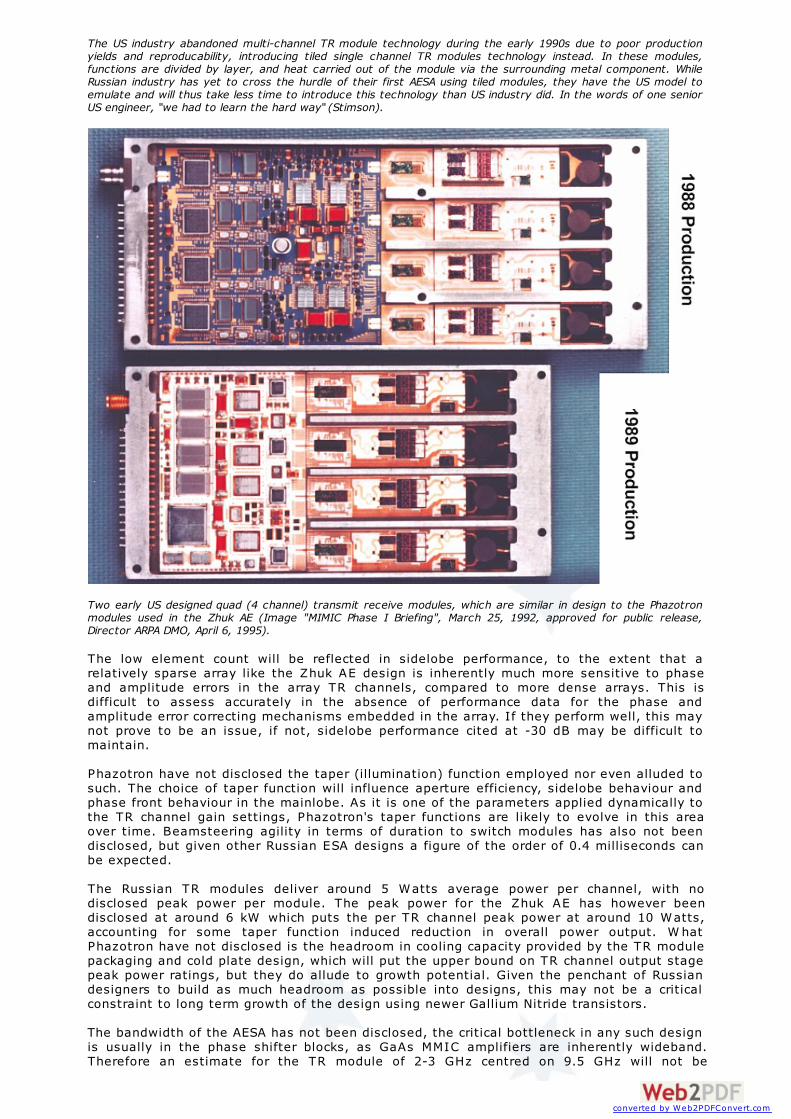
The US industry abandoned multi-channel TR module technology during the early 1990s due to poor productionyields and reproducability, introducing tiled single channel TR modules technology instead. In these modules,functions are divided by layer, and heat carried out of the module via the surrounding metal component. WhileRussian industry has yet to cross the hurdle of their first AESA using tiled modules, they have the US model toemulate and will thus take less time to introduce this technology than US industry did. In the words of one seniorUS engineer, "we had to learn the hard way" (Stimson).
Two early US designed quad (4 channel) transmit receive modules, which are similar in design to the Phazotronmodules used in the Zhuk AE (Image "MIMIC Phase I Briefing", March 25, 1992, approved for public release,Director ARPA DMO, April 6, 1995).
The low element count will be reflected in sidelobe performance, to the extent that arelatively sparse array like the Zhuk AE design is inherently much more sensitive to phaseand amplitude errors in the array TR channels, compared to more dense arrays. This isdifficult to assess accurately in the absence of performance data for the phase andamplitude error correcting mechanisms embedded in the array. If they perform well, this maynot prove to be an issue, if not, sidelobe performance cited at -30 dB may be difficult tomaintain.
Phazotron have not disclosed the taper (illumination) function employed nor even alluded tosuch. The choice of taper function will influence aperture efficiency, sidelobe behaviour andphase front behaviour in the mainlobe. As it is one of the parameters applied dynamically tothe TR channel gain settings, Phazotron's taper functions are likely to evolve in this areaover time. Beamsteering agility in terms of duration to switch modules has also not beendisclosed, but given other Russian ESA designs a figure of the order of 0.4 milliseconds canbe expected.
The Russian TR modules deliver around 5 Watts average power per channel, with nodisclosed peak power per module. The peak power for the Zhuk AE has however beendisclosed at around 6 kW which puts the per TR channel peak power at around 10 Watts,accounting for some taper function induced reduction in overall power output. W hatPhazotron have not disclosed is the headroom in cooling capacity provided by the TR modulepackaging and cold plate design, which will put the upper bound on TR channel output stagepeak power ratings, but they do allude to growth potential. Given the penchant of Russiandesigners to build as much headroom as possible into designs, this may not be a criticalconstraint to long term growth of the design using newer Gallium Nitride transistors.
The bandwidth of the AESA has not been disclosed, the critical bottleneck in any such designis usually in the phase shifter blocks, as GaAs MMIC amplifiers are inherently wideband.Therefore an estimate for the TR module of 2-3 GHz centred on 9.5 GHz will not be
converted by Web2PDFConvert.com

unreasonable, with potential for further growth with refinement of the gain/phase blockMMIC designs and packaging. This is however not consistent with the array design.
The upper frequency bound of the AESA will be determined by element spacing and gratinglobe formation, for the existing design this appears to be at 8.5 GHz assuming for adiamond lattice a 17.5 mm spacing in the horizontal plane. This suggests a usablebandwidth of around 1 GHz or less centred on less than 8.5 GHz, accuracy of measurementpermitting. The details of the radial feed have not been disclosed and this may furtherconstrain usable bandwidth. The literature cites "16 centre frequencies" which if separatedby 100 MHz bandwidth would suggest 1.6 GHz, feed permitting. This would put the centre ofthe band coverage at about 7.7 GHz which would be consistent with past practice.
Structural mode radar cross section should be reasonable for the tilted productionconfiguration, but less so for the demonstrator with is aligned in the vertical. The large edgearea surrounding the 0.6 metre aperture area in the 0.7 metre antenna structure providessome opportunity for lossy edge treatment, but none is visible on the demonstrator. Afrequency selective screen panel might also be employed, but was also not visible on thedemonstrator.
An aggregate noise figure for the receiver of 3 to 3.5 dB is not unreasonable. This wouldyield a highly competitive receive path sensitivity compared to current Western AESAs.Performance parameters for the ADC and master oscillator have not been disclosed.
Reliability of the Zhuk AE might not appear to be as good as Western AESAs due to thepackaging technology used, although Phazotron marketing material puts the figure at arespectable 900 hr MTBF which compares closely to the 917 hr MTBF of the more complex USAPG-79 AESA. This may reflect yet again the Russian propensity to overdesign components,which in a thermally challenged design amounts to using devices well below their maximumpower ratings.
In terms of gross power aperture performance the Zhuk AE looks good in peak power,competing well against all Flanker radars including the N011M BARS, but suffering like all F-16 and F/A-18 sized radars from a small aperture size, which compromises overall detectionrange performance.
In terms of growth in the design, as long as the existing packaging and thus elementspacing are used, increasing antenna bandwidth is likely to require centre operatingfrequencies well below 8 GHz. Clearly if the module cold plate design and cooling systemcan cope, there are no issues with boosting TR channel peak power output by using higherpower rated Gallium Nitride commercial transistors sourced in the West - this might well beworth doing even if it imposes duty cycle restrictions on maximum range search modes.Other important determinants of performance such as oscillator parameters and ADCdynamic range and noisiness have been conveniently omitted from the public disclosure.
W hat is clear is that a MiG-29/33/35 Fulcrum fitted with a Zhuk AE will robustly outperformbaseline F-16 and F/A-18 configurations, other than the F/A-18E/F/BII. It will not becompetitive against any F-15 radar.
converted by Web2PDFConvert.com
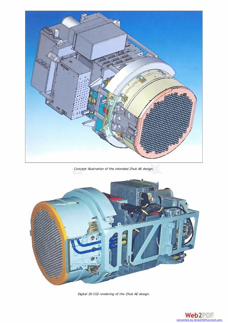
Concept illustration of the intended Zhuk AE design.
Digital 3D CGI rendering of the Zhuk AE design.
converted by Web2PDFConvert.com
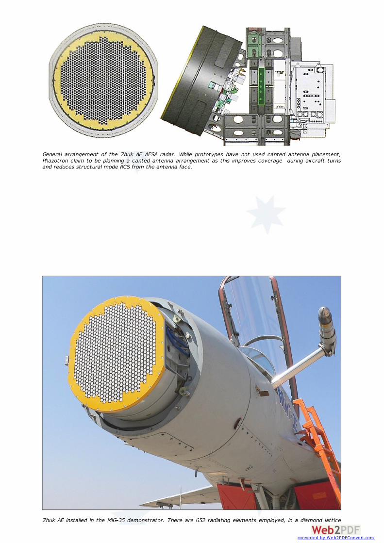
General arrangement of the Zhuk AE AESA radar. While prototypes have not used canted antenna placement,Phazotron claim to be planning a canted antenna arrangement as this improves coverage during aircraft turnsand reduces structural mode RCS from the antenna face.
Zhuk AE installed in the MiG-35 demonstrator. There are 652 radiating elements employed, in a diamond lattice
converted by Web2PDFConvert.com
pattern, each vertical row comprising groups of four quad TR modules, with a total of 163 used. This is aconceptually similar arrangement to the earliest US AESA arrangements, using a row length adjusted withdisplacement from the antenna centreline.
Zhuk AE AESA Specifications and Cardinal Design Parameters
Antenna Parameters Value Notes
TR Channels [-] 652
TR Modules [-] 163 quad modules Grouped in columns of 7, 6, 5, 4 and 3
Aperture Diameter [m] 0.6
Antenna Diameter [m] 0.7
Centre Frequency [GHz] 9.5
TR Channel Power CW [W] 5.0
Average Power [kW] 3.0
Peak Power [kW] 6.0 @ 50% Duty Cycle Calculated duty cycle
Emitter Pattern diamond lattice
Taper Function Undisclosed
First Sidelobe [dB] -30.0
Higher Order Sidelobes [dB] -50.0
Deflection Angle [deg] +/- 70.0 [-4 dB]
Grating Lobes Nil due element pitch
Phase Centres via Backplane Feed Dual Plane Monopulse
Backplane Feed Radial Waveguide
Amplitude Control Resolution [bits] 5
Phase Control Resolution [bits] 6
TR Channel Transmitter Gain [dB] 34.0
TR Channel Receiver Gain [dB] 30.0
TR Channel Receiver NF [dB] 2.5
TR Channel Phase Increment [deg] 5.625 Two stages - coarse 4-bit, fine 2-bit
TR Channel Gain Increment [dB] 0.7
TR Channel Dynamic Range [dB] 24.0
TR Channel PAE [%] 25.0
Phase Shifter Bandwidth [GHz] 4.0 - 14.0 8.0 - 11.0 GHz tested
Programmable Attenuator Bandwidth [GHz] 8.0 - 11.0
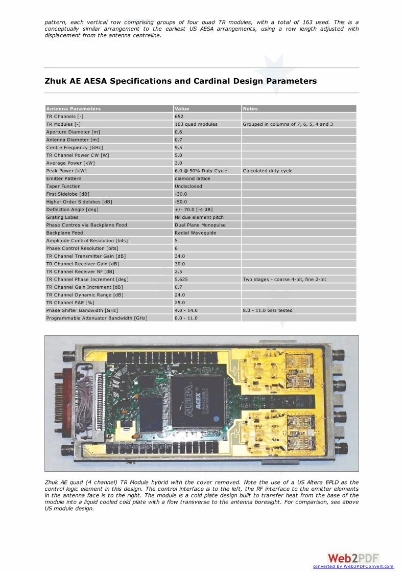
Zhuk AE quad (4 channel) TR Module hybrid with the cover removed. Note the use of a US Altera EPLD as thecontrol logic element in this design. The control interface is to the left, the RF interface to the emitter elementsin the antenna face is to the right. The module is a cold plate design built to transfer heat from the base of themodule into a liquid cooled cold plate with a flow transverse to the antenna boresight. For comparison, see aboveUS module design.
converted by Web2PDFConvert.com

GaAs 4-bit phase shifter MMIC die.
GaAs 2-bit phase shifter MMIC die.
GaAs Gain Controller MMIC die.
converted by Web2PDFConvert.com
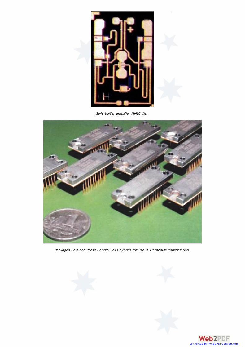
GaAs buffer amplifier MMIC die.
Packaged Gain and Phase Control GaAs hybrids for use in TR module construction.
converted by Web2PDFConvert.com
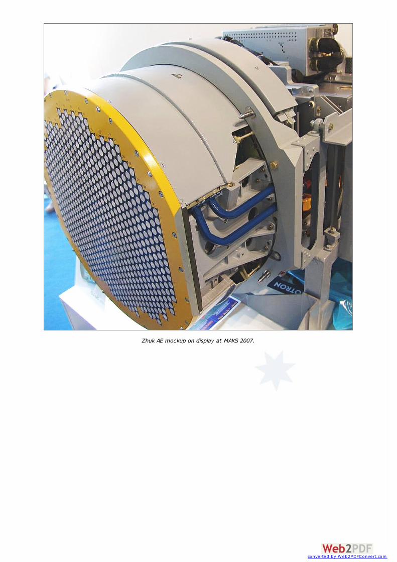
Zhuk AE mockup on display at MAKS 2007.
converted by Web2PDFConvert.com
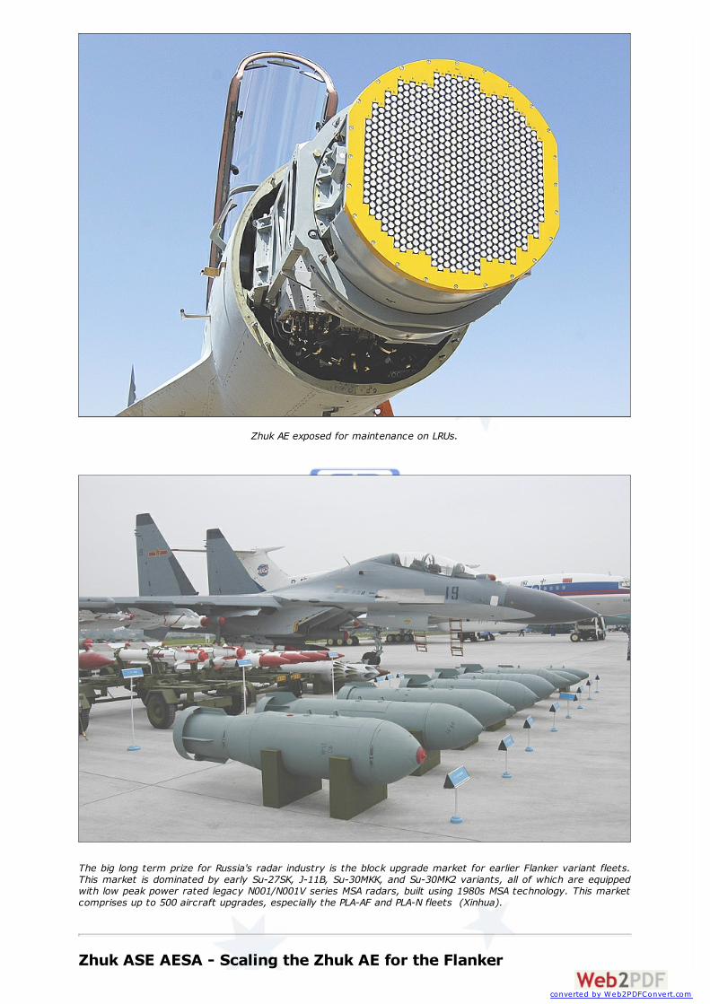
Zhuk AE exposed for maintenance on LRUs.
The big long term prize for Russia's radar industry is the block upgrade market for earlier Flanker variant fleets.This market is dominated by early Su-27SK, J-11B, Su-30MKK, and Su-30MK2 variants, all of which are equippedwith low peak power rated legacy N001/N001V series MSA radars, built using 1980s MSA technology. This marketcomprises up to 500 aircraft upgrades, especially the PLA-AF and PLA-N fleets (Xinhua).
Zhuk ASE AESA - Scaling the Zhuk AE for the Flanker
converted by Web2PDFConvert.com

One of the stated intentions of Phazotron is to scale up the Zhuk AE for the Flanker, in themanner of the Zhuk-27 and Zhuk-MSFE variants, using a 0.98 metre diameter aperture.
If we assume that such a scaled up design uses exactly the same quad module technologyas the Zhuk AE does, and an enlarged cooling plate and mounting frame, then theachievable performance will scale with the aperture size. For the 0.98 m antenna outsidediameter, assuming a similar unused area around the emitter array, the total usableaperture diameter will be around 0.8 metres, and the element count will sit at around 1160.If we assume tighter placement and a 1.1 metre antenna outside diameter, as used in thePero PESA, then the total usable aperture diameter will be around 0.95 metres, and theelement count will sit at around 1630, or about the same as the Zhuk-MSFE PESA design.
W ith a peak power rating of 10 Watts/channel the latter yields a peak power of the order of16.3 kW which results in a radar which outperforms the N011M BARS, APG-63(V)1, APG-71and APG-79 in raw power aperture performance. Such a radar could reach IOC around 2010 ifit is funded properly, in step with the timelines for the NIIP Irbis E.
If Phazotron improve the TR channel power rating as they have stated an intent to do, thenthe results bear some careful consideration. Tabulating options yields some interestingresults.
Estimated detection range chart for variants of the Zhuk ASE AESA equipped with a range ofTransmit Receive Module power ratings per channel. The detection range performance of the10 and 12 Watt module equipped Zhuk ASE is similar to the T ikhomirov NI I P I rbis-E hybridESA in the Su-35BM/Su-35-1, and much superior to the N011M BARS. T he performance ofZhuk ASE if equipped with modules rated above 15 Watts is superior to the I rbis E. Receivernoise figure and effective aperture area are assumed to be similar. N011M performance isbased on parametric data and is better than NIIP cited figures (Author).
Notional Zhuk ASE Estimated Power Aperture: ~1630 TR channels; 0.95 meteraperture diameter; NF=3.5 dBTR Channel Peak Power [W] Radar Ave Power [kW] Radar Peak Power [kW] PAPEAK [dBWm2]
10.0 8.15 16.3 40.6
12.0 10.0 20.0 41.5
15.0 12.25 24.5 42.4
20.0 16.3 32.6 43.6
25.0 20.4 40.8 44.6
Notional Zhuk ASE: Radars/Fighters Power Aperture ComparisonTR Channel Peak Power[W]
Radars Outperformed by Zhuk ASE Fighter Types Equipped
10.0 N011M BARS, APG-63(V)1, APG-70, APG-73, APG-79, APG-81 Su-30MK, F-15C/E, F/A-18A-G, JSF
12.0 N011M BARS, APG-63(V)1, APG-70, APG-73, APG-79, APG-81 Su-30MK, F-15C/E, F/A-18A-G, JSF
15.0 N035 Irbis E, N011M BARS, APG-63(V)1, APG-70, APG-73, APG- Su-30MK/35BM, F-15C/E, F/A-18A-
converted by Web2PDFConvert.com

79, APG-81 G, JSF
20.0 N035 Irbis E, N011M BARS, APG-63(V)1, APG-70, APG-73, APG-79, APG-81
Su-30MK/35BM, F-15C/E, F/A-18A-G, JSF
25.0 N035 Irbis E, N011M BARS, APG-63(V)1, APG-70, APG-73, APG-79, APG-81
Su-30MK/35BM, F-15C/E, F/A-18A-G, JSF
Once Phazotron have engineered a Zhuk ASE with ~1630 TR Channels, then scaling uppower aperture performance is only a matter of changing the TR Module design to use morepowerful transistors, and improving the per module heat transfer performance in the AESA.Both of the latter represent fairly low risk incremental design changes.
Much of the imperative in the US to pursue high density tiled packaging was the result of ahigh demand for reduced AESA mass production costs, good structural mode RCSperformance, and tight element spacing to maximise bandwidth, so as to expand thefunctions the AESAs could perform and to maximise LPI capability via frequency agility. It isnot entirely clear that these would be compelling near term motives for Russia's industry -they will become such as work on the avionics for the PAK-FA accelerates.
There can be absolutely no doubt that Phazotron will aggressively market the Zhuk ASE asan upgrade package into the established Flanker market, which could be as large as 500aircraft in China alone.
Acknowledgments
The author is indebted to all parties in Australia and overseas who reviewed the draft of thispaper, for their cogent comments and input.
References
1. «PHAZOTRON – NIIR» CORPORATION, Russia.123557, Moscow, Electrichesky Pereulok.,1.
2. Российская самолетостроительная корпорация «МиГ», Россия, 125284, Москва, 1-йБоткинский проезд, д.7
3. ОАО МНИИ "АГАТ", Joint stock company Moscow research institute «Agat». РоссийскаяФедерация, 140182, г. Ж уковский Московской области, ул. Туполева д. 2а.
4. "Центральное конструкторское бюро автоматики", Central Design Bureau Avtomatika,Адрес: 644027, г. Омск-27, Космический проспект, 24А
5. Государственное предприятие завод "Арсенал", Government Factory "Arsenal", 8,Moskovska str., Kiev, 01010, Ukraine
6. Irkut SPC (JSC), 125315, 68, Bldg. 1, Leningradsky prospekt, Moscow, 125315, Russia7. KnAAPO (JSC), ul. Sovetskaya, 1, Komsomolsk-on-Amur, 681018, Russia8. Фотогалерея первого построенного на КнААПО Су-35 (Imagery of first Su-35)9. Буклет Су-35, архив с буклетом в формате Adobe Reader.(Booklet Su-35)
10. Презентационное видео о Су-35.(Su-35 presentation)11. Основные характеристики Су-35. Видео (Su-35 features - video)12. Sukhoi Company (JSC), 23B, Polikarpov str.,Moscow, 125284, Russia, p/b 60413. Su-35. Multirole Super-Maneuverable Fighter. The Booklet. KNAAPO/Sukhoi brochure
(Zipped PDF 16 MB)14. Kopp, C., Australian Aviation - June 2002 - Active Electronically Steered Arrays - A
Maturing Technology
Bibliography
1. Guskov Y., Active Phased Array Radar: History and Progress Made, Phazotron,Information and Analytical Magazine of the Phazotron NIIR Corporation, Special Issue,AeroIndia 2007.
2. Dolgachev A, Optimising Active Phased Arrays, Phazotron, Information and AnalyticalMagazine of the Phazotron NIIR Corporation, Special Issue, AeroIndia 2007.
3. Dolgachev A, X-Band Active Phased Array: Scope of Work Report, Phazotron,
converted by Web2PDFConvert.com

Information and Analytical Magazine of the Phazotron NIIR Corporation, Special Issue,AeroIndia 2007.
4. Semyonov E. et al, Compact Amplitude Phase Control Module for X-band Active PhasedArray Transceivers, Phazotron, Information and Analytical Magazine of the PhazotronNIIR Corporation, Special Issue, AeroIndia 2007.
5. Guskov Y. and Frantsev V., Phazotron Single Basis Radars, Phazotron, Information andAnalytical Magazine of the Phazotron NIIR Corporation, Special Issue, AeroIndia 2007.
6. Viktorov I. and Frantsev V., Phazotron Radars as an Upgrade Opportunity for TacticalAircraft, Phazotron, Information and Analytical Magazine of the Phazotron NIIRCorporation, Special Issue, AeroIndia 2007.
7. Kanashchenkov A., PHAZOTRON - DEVELOPER AND MANUFACTURER OF STATE-OF-THE-ART RADAR FAMILIES FOR FIGHTER AIRCRAFT, Military Parade, 1997.
8. Stimson G.W ., Introduction to Airborne Radar, 2nd Edition Scitech Publishing, 1998(highly recommended).
9. Skolnik M.I. (Editor), Radar Handbook 3rd Edition, 007057913X, McGraw-Hill, February,2008 (highly recommended).
10. Bassem R. Mahafza, Introduction to Radar Analysis, CRC Press, ISBN 0849318793.
(Images Rosoboronexport, RuMoD, Phazotron, KnAAPO, MiGAvia.ru, US DoD, Other, Author)
Endnotes
[1] Phazotron's designation nomenclature appears to follow the pattern of M-improved, S-Sukhoi, F-PESA, A-AESA,E-Export, with additional designators as required.[2] Phazotron have not disclosed the insertion loss between the radiating element and the TR channel, so theaggregate noise figure will be degraded by the size of that insertion loss. For 0.5 to 1 dB this yields noise figures of3.0 - 3.5 dB which is consistent with other Russian radars using antenna mounted amplifiers.
Technical Report APA-TR-2008-0403
Artwork, graphic design, layout and text © 2004 - 2014 Carlo Kopp; Text © 2004 - 2014 Peter Goon; All rightsreserved. Recommended browsers. Contact webmaster. Site navigation hints. Current hot topics.
Site Update Status: $Revision: 1.753 $ Site History: Notices and Updates / NLA Pandora Archive
Save Page as PDF Tweet Follow@APA_Updates
Select LanguagePowered by Translate
converted by Web2PDFConvert.com

converted by Web2PDFConvert.com