Phase locked loop design
14
Introduction What is a PLL? Parts of a PLL. Working of PLL.
-
Upload
moin-aman -
Category
Engineering
-
view
491 -
download
9
Transcript of Phase locked loop design
Introduction
What is a PLL?
Parts of a PLL.
Working of PLL.
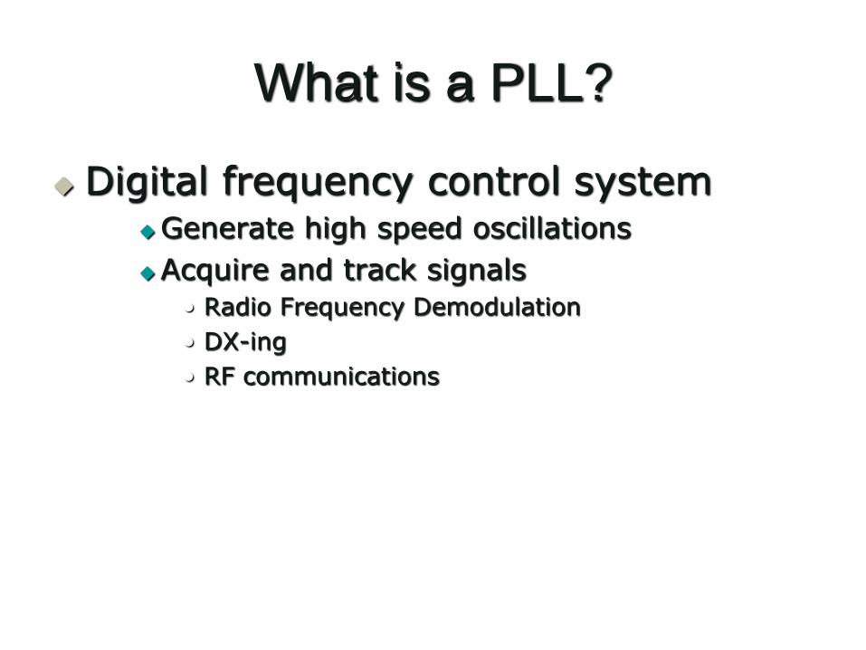
What is a PLL?
Digital frequency control systemGenerate high speed oscillations
Acquire and track signals
• Radio Frequency Demodulation
• DX-ing
• RF communications
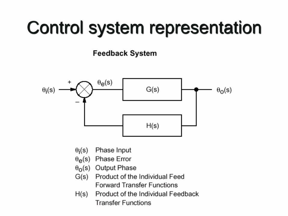
Control system representation
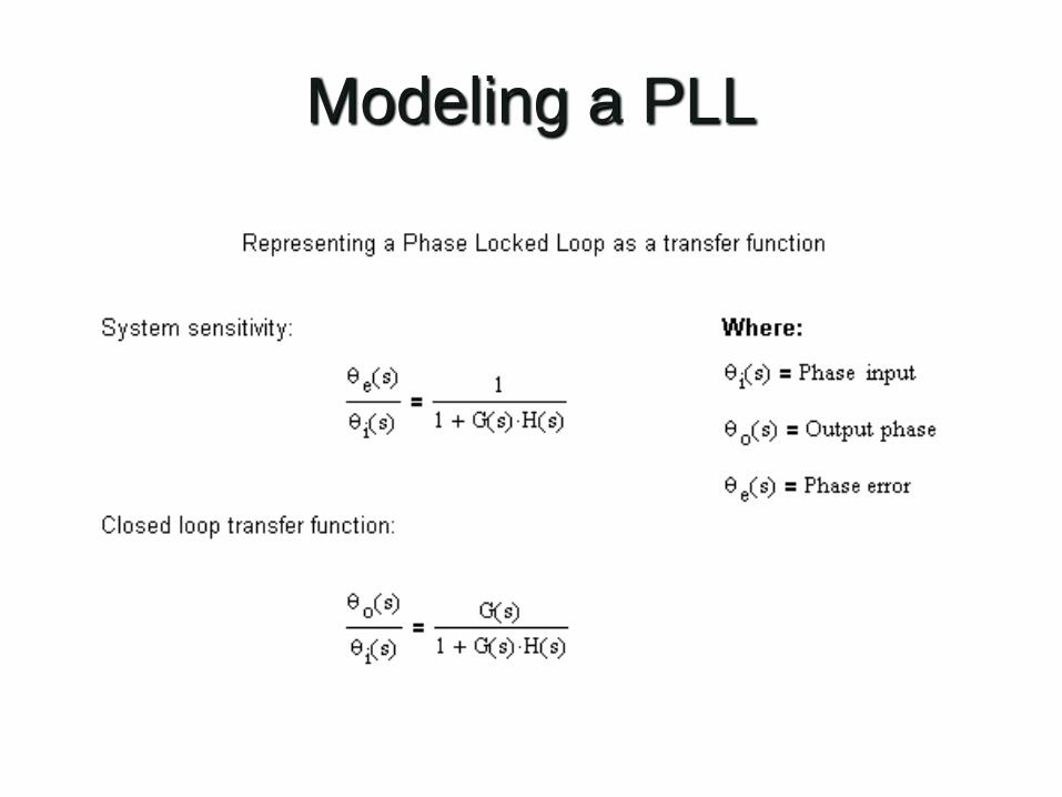
Modeling a PLL
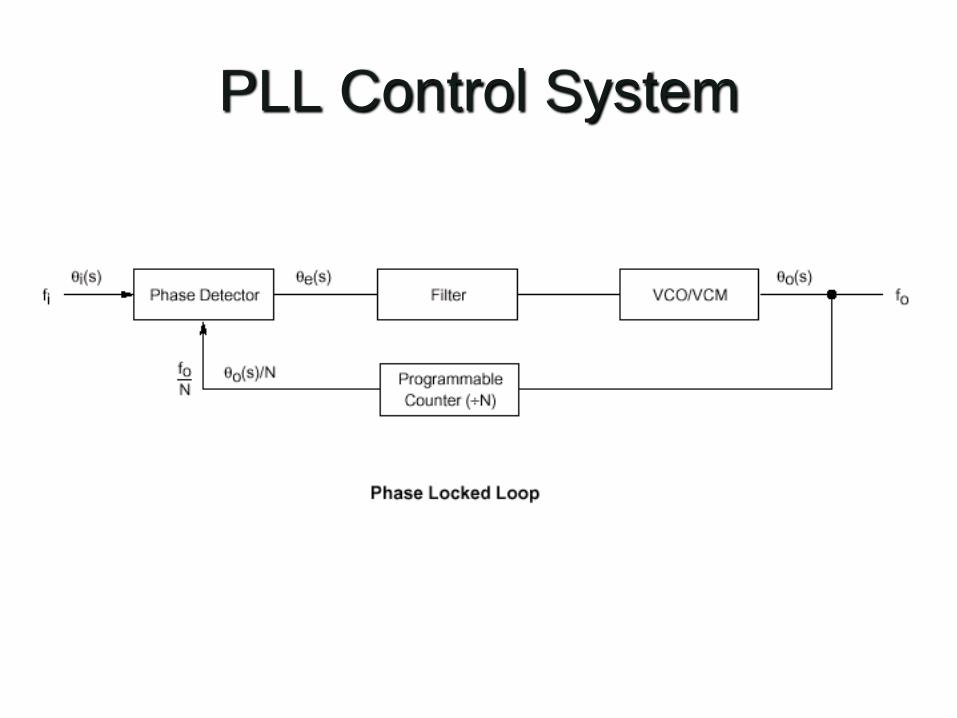
PLL Control System
Parts of a PLL
Phase Detector
Filter
Voltage Controlled Oscillator
Programmable Counter
Parts of a PLL
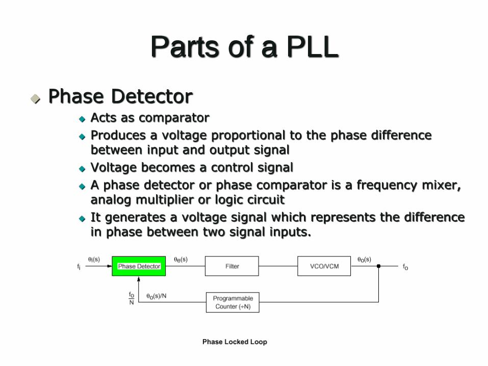
Phase Detector Acts as comparator
Produces a voltage proportional to the phase difference between input and output signal
Voltage becomes a control signal
A phase detector or phase comparator is a frequency mixer, analog multiplier or logic circuit
It generates a voltage signal which represents the difference in phase between two signal inputs.
Parts of a PLL
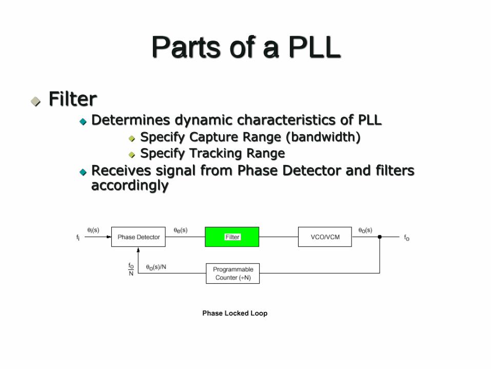
Filter Determines dynamic characteristics of PLL
Specify Capture Range (bandwidth)
Specify Tracking Range
Receives signal from Phase Detector and filters accordingly
Parts of a PLL
Filter (Cont.) It provides a smoother form of a signal, removing
the short-term fluctuations, and leaving the longer-term trend.
PLL loop filter (usually a low pass filter) generally has two distinct functions.
The primary function is to determine loop dynamics, also called stability. This is how the loop responds to disturbances, such as changes in the reference frequency.
Parts of a PLL
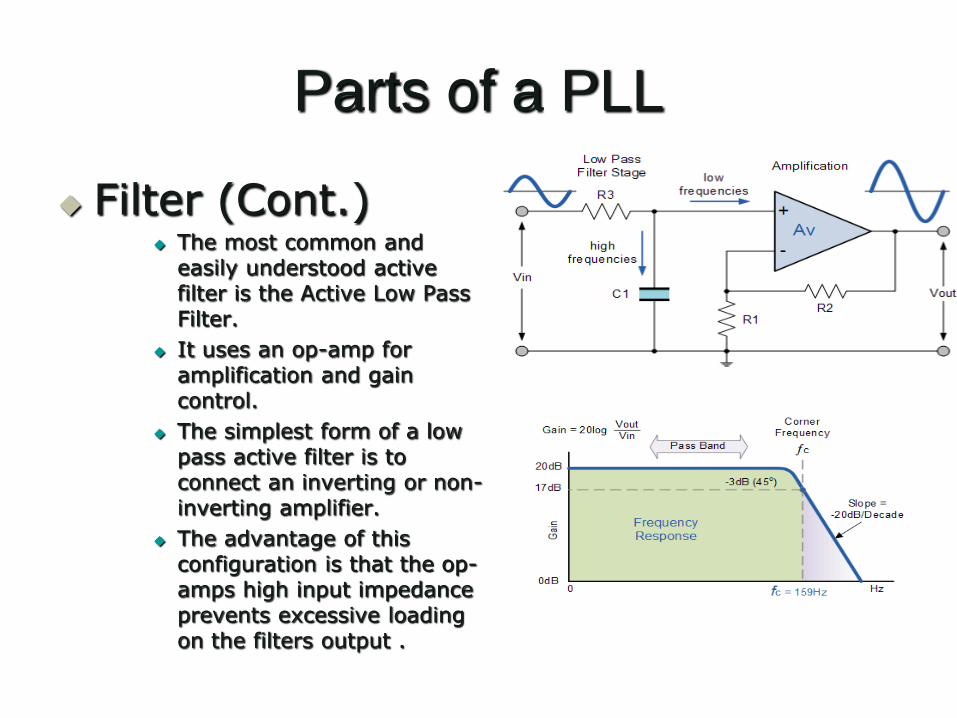
Filter (Cont.) The most common and
easily understood active filter is the Active Low Pass Filter.
It uses an op-amp for amplification and gain control.
The simplest form of a low pass active filter is to connect an inverting or non-inverting amplifier.
The advantage of this configuration is that the op-amps high input impedance prevents excessive loading on the filters output .
Parts of a PLL
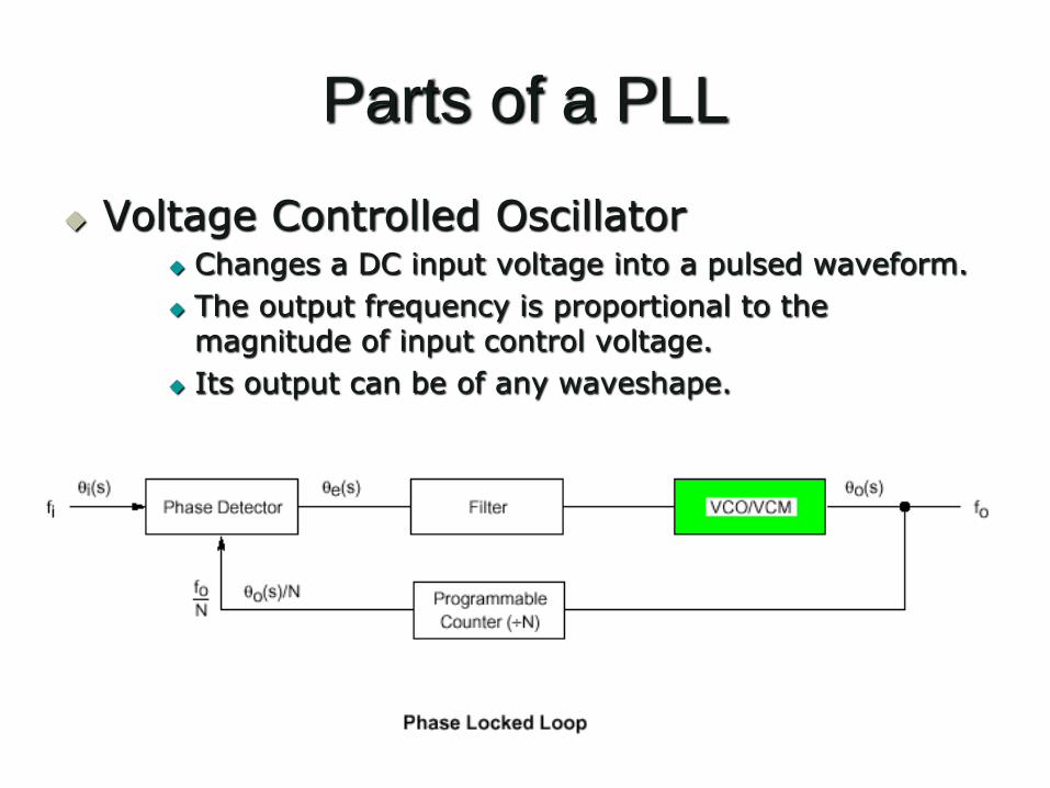
Voltage Controlled Oscillator Changes a DC input voltage into a pulsed waveform.
The output frequency is proportional to the magnitude of input control voltage.
Its output can be of any waveshape.
Parts of a PLL
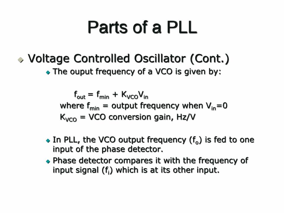
Voltage Controlled Oscillator (Cont.) The ouput frequency of a VCO is given by:
fout = fmin + KVCOVin
where fmin = output frequency when Vin=0
KVCO = VCO conversion gain, Hz/V
In PLL, the VCO output frequency (fo) is fed to one input of the phase detector.
Phase detector compares it with the frequency of input signal (fi) which is at its other input.
Parts of a PLL
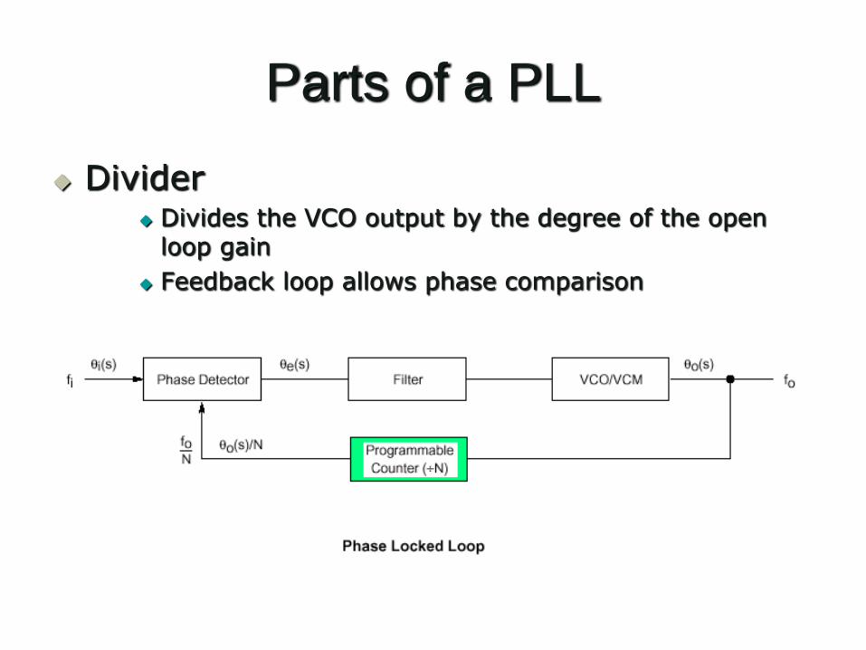
Divider Divides the VCO output by the degree of the open
loop gain
Feedback loop allows phase comparison
Parts of a PLL
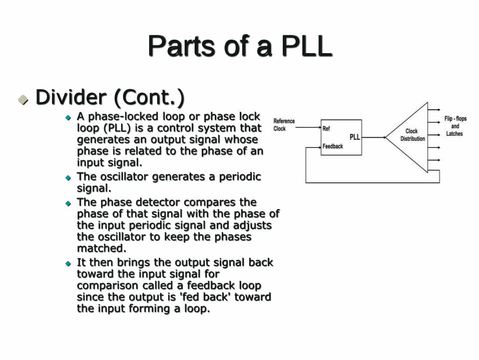
Divider (Cont.) A phase-locked loop or phase lock
loop (PLL) is a control system that generates an output signal whose phase is related to the phase of an input signal.
The oscillator generates a periodic signal.
The phase detector compares the phase of that signal with the phase of the input periodic signal and adjusts the oscillator to keep the phases matched.
It then brings the output signal back toward the input signal for comparison called a feedback loop since the output is 'fed back' toward the input forming a loop.


![PHASE-LOCKED LOOP SIMULATIONS USING T-SPICE Contents · Phase Lock Loop Simulations [1] PHASE-LOCKED LOOP SIMULATIONS USING T-SPICE Contents: • A Brief Introduction to T-Spice •](https://static.fdocuments.in/doc/165x107/5adfd3d67f8b9a1c248c7fb4/phase-locked-loop-simulations-using-t-spice-lock-loop-simulations-1-phase-locked.jpg)