Phase Based, Automatic Resonance Finder
9
6.101 Final Project Report Phase Based, Automatic Resonance Finder Alec Reduker
Transcript of Phase Based, Automatic Resonance Finder

6.101 Final Project Report
Phase Based, Automatic Resonance Finder
Alec Reduker

Abstract:
The goal of this project is to build a circuit that will automatically drive a resonant circuit at resonance through a coil as well as display the resonant frequency. It does so through a feedback loop with a robust, new, phase detector and a voltage controlled oscillator. The circuit is sound in theory, however; there are some practical limitations of the VCO that inhibit it from true utility. The project started as a way to power and read different types of proximity cards without manual tuning, but it has applications in radio electronics as well as other fields. The most probable use of this technology would be to optimize resonance of a circuit where a vague resonant frequency is already known.
The circuit is essentially a controller on a Voltage Controlled Oscillator (VCO) that uses the phase difference between the input and the response as an error signal. It operates on the principle that when an LC circuit is driven at resonance, there is no phase difference between the input and the response. The response can either be a voltage measured directly on the circuit of interest, or the power dissipated through the primary coil. The power dissipated is measured by a small resistor in series with the primary coil. This works because the amplitude of this signal is not important, only the phase is -- the voltage across this resistor will be in phase with the power dissipated in the primary.
There are three main blocks of the circuit: The VCO, the Phase Detector, and the Controller.
Figure 1

There is already an instrument to measure the resonant frequency of LC circuits -- called a grid dip meter. A grid dip meter operates by sweeping a wide range of frequencies on a transmitter (coupled to the subject circuit), and detecting where there is a ‘dip’ in the power taken from the oscillator. The dip point is where resonance is achieved. Grip dip meters are not used regularly anymore and buying one is like shopping for an antique.
This circuit differs mainly on principle, and has advantages and disadvantages compared to a grid dip meter. The biggest difference is that the grid dip meter still requires manual tuning of the oscillator. The phase is a clearer signal to work with, and by using feedback, this circuit could automatically tune. Voltage Controlled Oscillator:
In order for the project to be realistically effective, it needed a very wide band VCO which operated at relatively low frequencies (< 100KHz). If the VCO was not very wide band, the circuit would be useless, as the user would have to have fairly accurate prior knowledge on your circuit’s resonant frequency. This task is not trivial. The Colpitts oscillator provided a lot of things that were beneficial to the circuit -- it is very stable, and has terrific phase noise. Phase noise is especially important because my circuit relies on the phase. An unforeseen problem with the Colpitts oscillator was that it is generally used at high frequencies. There is no reason that it can’t be used at low frequencies, but doing so requires a relatively large capacitor/inductor pair. Since most tuning capacitors are on the order of picofarads, it needed very large inductors. Most of the the inductors used in testing and the final product were hand wound, so the inductance could be chosen and changed on a whim.
A Colpitts Oscillator consists of a resonant tank circuit paired with a gain device -- a BJT in my case. The tank circuit uses a capacitive divider to send some of the response to the output, and some back into the base of the transistor. The gain of the amplifier multiplied by the fraction of feedback fed back into the base must be greater than or equal to 1 in order for the circuit to oscillate. C1 and C6 of figure 2 isolate the tank circuit from the DC biasing set by R1 and R2. L1 acts as an RF choke.
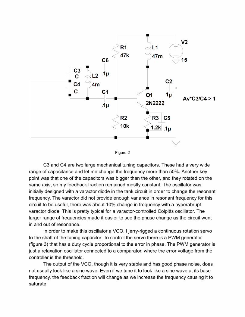
Figure 2
C3 and C4 are two large mechanical tuning capacitors. These had a very wide
range of capacitance and let me change the frequency more than 50%. Another key point was that one of the capacitors was bigger than the other, and they rotated on the same axis, so my feedback fraction remained mostly constant. The oscillator was initially designed with a varactor diode in the tank circuit in order to change the resonant frequency. The varactor did not provide enough variance in resonant frequency for this circuit to be useful, there was about 10% change in frequency with a hyperabrupt varactor diode. This is pretty typical for a varactor-controlled Colpitts oscillator. The larger range of frequencies made it easier to see the phase change as the circuit went in and out of resonance.
In order to make this oscillator a VCO, I jerry-rigged a continuous rotation servo to the shaft of the tuning capacitor. To control the servo there is a PWM generator (figure 3) that has a duty cycle proportional to the error in phase. The PWM generator is just a relaxation oscillator connected to a comparator, where the error voltage from the controller is the threshold.
The output of the VCO, though it is very stable and has good phase noise, does not usually look like a sine wave. Even if we tune it to look like a sine wave at its base frequency, the feedback fraction will change as we increase the frequency causing it to saturate.

Figure 3 Phase Detector:
Though XOR phase detectors are common-place, they only work with two square waves of 50% duty cycle. The key points of this project’s phase detector are its ability to deal with different waveforms, different duty cycles, and different amplitudes -- perhaps like the input and response in figure 4. It is important that it can handle two different waveforms and duty cycles because because the output shape of the VCO changes drastically with frequency. At low frequencies it may be close to a sine wave, but at higher frequencies the waveform could be completely different. The response, though it may be a sin wave, will certainly be smaller in amplitude.
Having these two drastically different waveforms rules out phase detection by frequency mixing, so an XOR based phase detector is preferred -- if there are two pulse waves (A and B) with 50% duty cycle and equal frequency, then A XOR B (low passed heavily) will produce a voltage proportional to the phase difference. Notice the conditions for this phase detector to work -- the signals must have a 50% duty cycle, and equal frequency. On top of this, both signals have to be a suitable level to trigger “high” on the XOR gate.

These conditions are fulfilled by first running our signals through comparators so they have a reasonable amplitude. Next, this signal is passed through a frequency divider. The frequency divider is just two D-type flip flops with simple feedback, the output of the frequency divider will follow the rising edges only, and thus the frequency will be halved, and we will have 50% duty cycle. The phase will be maintained despite the change in frequency. An added benefit of this is that, since the operating frequency is lowered significantly, the response time of our XOR gate will not as easily limit our maximum frequency. Theoretically, multiple frequency dividers could enhance this effect while maintaining the phase, however, the response times of the comparators quickly become a new bottleneck. The XOR gate is constructed from MOSFET’s using a “pass transistor” topology. This means that all redundant transistors have been eliminated. 1
Comparators Freq. Divider XOR
Figure 4
1 Anis, M. (2008). ECE637: Digital CMOS Integrated Circuits, Lecture 11 [PowerPoint Slides] . Retrieved from https://ece.uwaterloo.ca/~mhanis/ece637/lecture11.pdf

Figure 5
Results/Improvements:
The biggest success of the project was the phase detector, it did exactly what it was supposed to. I created a phase detector that was robust to two radically different waveforms, as long as they were the same frequency. The only improvement I would have made to the phase detector is to replace the comparators in figure 5 with Schmitt Triggers. Sometimes, if the response had a small enough amplitude, noise would cause the comparators to trigger multiple times on one edge and hysteresis would fix this.
As is the case with any project, I ran into countless roadblocks and unexpected turns. The biggest of these was that building the VCO that I needed was a very substantial project in itself. Creating a suitable VCO was extremely challenging, and took up the majority of my time working on the project. When I started researching this task seriously, I didn’t find anything that achieved a fraction of what I was hoping for. This quickly diminished some of my optimism for the end functionality of the project. It is not even remotely possible to create one oscillator that will oscillate from 0-1MHz. Many commercial VCO’s only vary their frequency by a few percent. These harsh truths were not obvious when I started building my VCO. Had I not chanced upon a very large tuning capacitor, I would have been dead in the water at this point. By the time I had a

VCO that I was comfortable with, I didn’t have much time to perfect the rest of my circuit.
Even the VCO I have now could be improved substantially by adding more variable capacitance. Currently I can detect resonance from only about 170KHz-220KHz. Another possible improvement to the VCO could be to switch to a Hartley oscillator. The Hartley oscillator maintains the great stability and phase noise of the Colpitts oscillator, but could keep the feedback fraction constant while changing the capacitance because the feedback is determined by inductors. Alternatively I could have kept using a Colpitts oscillator, and used a variable inductor instead of a variable capacitor to keep the feedback fraction constant. Keeping the feedback fraction constant would have given me much more control over the shape of the VCO output, and would have made it less apt to saturate as the frequency was increased.
My final product was one step away from a working prototype. I made too many changes to my circuit too late in the timeline of the project, and I couldn’t get all of the parts I needed. As of today, the circuit still requires some manual tuning, as the mechanical coupling between the servo and the tuning capacitor doesn’t exist. LED’s show the user whether they are above or below the resonant frequency and tuning to resonance is as simple as turning a single knob until the LED’s show that you have reached resonance.

Figure 6