PHABRIX Sx range - avbb.net
17
PHABRIX Sx range Battery Replacement Manual PHSXPN-1001
Transcript of PHABRIX Sx range - avbb.net

PHABRIX Sx range
Battery Replacement Manual PHSXPN-1001

Release information
Manual Release: PHSXPN-1001 19 May 2015
Disclaimer
Copyright © PHABRIX Ltd. All rights reserved. Software products licensed are owned by PHABRIX Ltd and are protected by international treaty provisions and national copyright laws.
No part of this document may be reproduced, stored in a retrieval system or transmitted in any form or by any means, electronic, mechanical, recorded or otherwise without the prior written consent of PHABRIX Ltd.
The information in this document has been produced by PHABRIX Ltd with care and is believed to be accurate.
PHABRIX Ltd does not assume responsibility for loss or damage resulting from errors, omissions or inaccuracies
herein. This document is subject to change and revisions may be made and issued to include such changes.
Contact details PHABRIX Ltd. Omega House, Enterprise Way, Thatcham Berkshire, RG19 4AE, United Kingdom Tel: +44(0)1635 87 30 30 Web: www.phabrix.com email [email protected]
RMAs
Units that are to be returned to PHABRIX for repair must have a Return Merchandise Authorization (RMA) number. It is IMPORTANT that a RMA letter and number is issued by PHABRIX BEFORE the unit is returned. To request a RMA number email; [email protected] Sx Range Service Manual Page 1

Safety
ESD Protection Please use anti static wrist straps and a properly grounded work area when servicing this product. Avoiding Personal Injury
This instrument is serviceable by qualified personnel only. No user serviceable parts are provided. Units should be returned to your local PHABRIX agent for servicing.
The Operator should NOT remove the case from the unit. Do not spill any liquid onto the unit or its power adaptor.
Power supply
Make sure that the unit is connected to the correct power supply voltage. A power supply adaptor is supplied
with the unit which may be connected to any AC power supply between 100 and 240VAC at 50-60Hz. Only the
supplied power adaptor should be used with the unit. Do not use a damaged AC cable with the unit as it may
cause a shock or fire hazard. Replacement AC cables are available from your local PHABRIX agent.
If the battery is at too low a voltage for correct operation, the unit will not fully power up but will wait until the AC adaptor is connected. The LCD screen will display a warning message if this is true.
Operating Temperature
The unit should only be operated between 0 and 40 °Centigrade. If the unit is operated at a higher temperature there is a possibility of a fire hazard. If the temperature is changed rapidly from a cold
environment to a hot environment, moisture can be created internally which can cause malfunction or damage the unit. Allow the unit to sit for 30 minutes without power applied to reduce any possibility of condensation.
Input/Output terminals
Do not connect the input or output BNC connectors to external power as this can damage the internal circuitry and cause the unit to work incorrectly.
When not in use Disconnect the unit from the power supply and AC power source when not in use. Sx Range Service Manual Page 2

Maintenance
Wipe the case and buttons gently with a soft cloth lightly dampened with a neutral cleaning agent. A screen
cleaning cloth may be used to clean the LCD. Do not apply force to the LCD when cleaning or it may become
damaged.
Remove the power supply from the unit and turn OFF before cleaning. Do not allow any water or other liquid to enter the unit while cleaning.
Sx Range Service Manual Page 3

Servicing This manual describes how to replace the Lithium ion battery fitted to the Sx product range of hand held units.
Replacing the battery should take no longer than 30 minutes .
Before beginning work on the SX unit please observe the correct anti-static handling procedures.
Ensure the unit is switched off and the DC power lead is disconnected.
Only the disassembly procedure is described in this manual. To assemble the unit, reverse the process.
Tools
The Sx unit is a relatively simple assembly and requires few tools. #2 pozidrive screwdriver Endplates / PCB fixing screws Small flat bladed screwdriver Loudspeaker 14mm box spanner BNC retaining nuts M3 box spanner SxD/E fan and speaker bracket M2.5 box spanner SxD/E fan Fine tip pliers Keyboard locating pegs Scraper Removing battery foam
When replacing parts in the Sx range always replace the nuts and screws for new ones.
Sx Range Service Manual Page 4

End cap removal To expose the endplates and case fixing screws remove the rubber end caps. Gently peel them off each end remembering to prise them over the retaining lugs on each end plate.
Retaining lug
Sx Range Service Manual Page 5

LAN end plate
Removing the LAN end plate does not require the case to be separated. Remove the rubber end cap (see page 8) then remove the 4 countersink screws.
Remove and replace the LAN end plate.
Sx Range Service Manual Page 6

Case separation The printed circuit board that contains the BNCs is attached to the base metalwork so to separate the case remove the top 2 countersink screws on the BNC end plate and all screws holding on the LAN plate. Each case half contains a printed circuit board connected via 2 multi-way connectors located under the row of
switches. When separating the case, gently pull the 2 halves apart without twisting as this may cause damage.
There is also a speaker cable linking the case halves in the SxA and fan and speaker cables in the SxD and SxE. Once apart disconnect the cables.
Multiway connectors
Sx Range Service Manual Page 7

The speaker cable on the SxE is routed behind the multi way connectors. It is important that it is placed in this position when re-assembling. Routing the speaker on the SxA and SxD is not important.
Cable routing SxD and SxE internal connections.
Sx Range Service Manual Page 8
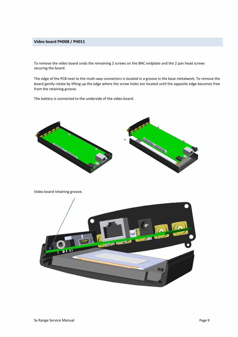
Video board PH008 / PH011 To remove the video board undo the remaining 2 screws on the BNC endplate and the 2 pan head screws securing the board.
The edge of the PCB next to the multi-way connectors is located in a groove in the base metalwork. To remove the
board gently rotate by lifting up the edge where the screw holes are located until the opposite edge becomes free
from the retaining groove. The battery is connected to the underside of the video board. Video board retaining groove.
Sx Range Service Manual Page 9

Battery connections When refitting curl the cable inboard so it sits behind the pin strip connector and can’t be seen when the LAN end plate is off.
Sx Range Service Manual Page 10

Li-polymer Battery The Li-Polymer battery is located in the base metalwork underneath the main video
board. To remove the board refer to the Video board section on page 12
The battery is connected to the underside of the video board.
Disconnect the battery then remove from the foam pocket.
The Li-Polymer battery MUST be disposed of according to local regulations. Sx Range Service Manual Page 11
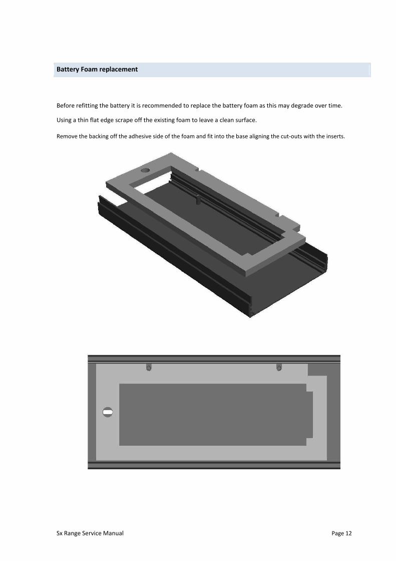
Battery Foam replacement Before refitting the battery it is recommended to replace the battery foam as this may degrade over time.
Using a thin flat edge scrape off the existing foam to leave a clean surface.
Remove the backing off the adhesive side of the foam and fit into the base aligning the cut-outs with the inserts. Sx Range Service Manual Page 12

Refit battery then reassemble. Lithium Polymer battery and Foam. Part # PHSXPN-1001 Sx Range Service Manual Page 13

Operating conditions
External Power Supply
DC-5V 5V
Maximum Input signals
SDI input(s) +/- 2V REF input: +/- 2V
LCD Monitor
The LCD may have some pixels that are always turned ON or always turned OFF. This is normal and should not affect normal operation.
LCD Flicker
The unit supports many video standards. The input SDI signal is displayed asynchronously and may flicker on the
waveform display or picture display. The unit stores the input SDI signal internally, and then reads the internal
frame using the LCD sync signal, which is asynchronous to the input SDI signal. LCD flickering may occur if a
frame is skipped or repeated.
Remote Network Operation
Remote network operation is only guaranteed when connected to a local machine.
Disposing of the unit
This product is subject to the European WEEE (Waste Electrical and Electronic Equipment) directive and should be disposed of according to the regulations of each country. This unit contains a Lithium Polymer battery which should be disposed of correctly. Sx Range Service Manual Page 14

Specifications
LCD Display
Display Type 4.3 inch TFT colour
Display Format: 480 x 272 24 bits
Backlight Variable brightness
Screen Saver Reduces brightness after user adjustable time under battery operation.
SDI Inputs
Supported standards 525/59.94, 625/50, 720p/23.98,24/25/29.97/30/50/59.94/60 1035i/59.94/60 1080psF/23.98,24/25/29.97/30 1080i/50/59.94/60
1080p/23.98,24/25/29.97/30/50/59.94/60
Connector BNC
Input Impedance 75 ohm terminated
Input Return Loss >= 15dB (5MHz to serial clock frequency)
Maximum Input Voltage +/- 2V
AES Inputs
Connector BNC
Input Impedance 75 ohm terminated
Maximum Input Voltage +/- 2V
Sample Rates The input has a sample rate converter and so will accept any sample rate
from 32kHz to 192kHz.
AES Outputs
Connector BNC
Input Impedance 75 ohm terminated
Sample Rate 48kHz Sx Range Service Manual Page 15

External Reference
Input Signal Tri-level or Bi-Level (black burst) syncs 50/59.94/60Hz
Connector BNC
Input Impedance 75 ohm terminated
Maximum Input voltage +/- 2V
External Control
Ethernet IEEE802.3 100Mb/s
Ethernet Connector RJ-45
USB USB 1.1 OTG (On the go - simulates flash disk)
USB Connector Mini-AB
Headphone Output
Connector Miniature 3.5mm Stereo Jack
General
Environment
Operating Temperature 0-40 °C
Operating Humidity <85% RH (no condensation)
Power Requirements AC 90-250V 50/60Hz 10W max
Dimensions 230 (L) x 93(H) x 45(D) mm
Weight 2kg
Accessories Instruction Manual on CD
AC Adaptor Power Cord
Carry Case
Sx Range Service Manual Page 16