Ph. 0800 TRICLAD · PDF file Ph. 0800 TRICLAD 4 1. Application and Scope 1.1. Application...
31
www.triclad.co.nz Ph. 0800 TRICLAD 1
Transcript of Ph. 0800 TRICLAD · PDF file Ph. 0800 TRICLAD 4 1. Application and Scope 1.1. Application...

www.triclad.co.nz Ph. 0800 TRICLAD 1

www.triclad.co.nz Ph. 0800 TRICLAD 2
Contents
1. Application and Scope 1.1 Application
1.2 Scope
1.3 Detail
1.4 Specific Design
2. Components 2.1 Profiles
2.2 Flashings
2.3 Primer
3. Nail Requirements
4. Design 4.1 Compliance
4.2 Responsibility
4.3 Clearance
5. Framing 5.1 Framing Grade
5.2 Dimensions
5.3 Treatment
5.4 Construction
6. Wall Underlay 6.1 Flexible Wall Underlay
6.2 Rigid Wall Underlay
7. Cavity Battens
8. Vermin Proofing
9. Flashings
10. Triclad Laps 10.1 Horizontal Laps
10.2 Vertical Laps
11. Cut Ends
12. Sealants
13. Durability 13.1 50 Year Durability

www.triclad.co.nz Ph. 0800 TRICLAD 3
13.2 15 Year Durability
14. Coatings
15. Maintenance
16. Handling and Storage
17. Drawing Directory

www.triclad.co.nz Ph. 0800 TRICLAD 4
1. Application and Scope
1.1. Application
Triclad Weatherboards are made from 12 and 17mm BD CarterHoltHarvey Bandsawn plywood. They are LOSP treated
and pre-primed. Under NZS3604 Triclad weatherboard is classed as a lightweight cladding product.
Triclad Lapped Weatherboard
Triclad Lapped Weatherboard has a Bandsawn Finish and is available in thicknesses of 12mm and 17mm with four
different widths available- 145mm, 190mm, 230mm and a 295mm (which is only available in 17mm thickness) with all
coming in 4.8metre lengths.
Triclad Rusticated Weatherboard
Triclad Rusticated Weatherboard has a Bandsawn Finish and is available in a thickness of 12mm with two different widths
available- 190mm and 230mm with all coming in 4.8metre lengths.
Triclad Vertical Weatherboard
Triclad Vertical Weatherboard has a Bandsawn Finish and is available in a thickness of 12mm with a widths of 190mm and
comes in 4.8metre lengths.
Triclad Board and Batten
Triclad Board and Batten has a Bandsawn Finish and is available in a thickness of 12mm with the board at a width of
230mm and Batten with a width of 70mm, both come in 4.8metre lengths. We can upon request manufacture 1200mm x
2.4,2.7,3.0,3.6,4.2,4.8 and 5.4m Boards.
1.2. Scope This specification covers the use of Triclad Weather Boards that fall within the scope of NZS 3604. This specification
covers the use of Triclad Weatherboards in both direct fixed and cavity construction methods and is limited to the
materials, products and processes contained herein, for buildings within the scope of NZS 3604:
• Up to 3 storey’s with a height measured from lowest ground level adjacent to the building to the highest point of the
roof (except for chimneys, aerials and the like) of 10 m or less, and
• With floor plan area limited only by seismic and structural control joints, and
• External walls that are vertical, and roofs that are 60º or less above the horizontal. Where buildings are based on NZS
3604, but require specific engineering design input, the framing shall be of at least equivalent stiffness to the framing
provisions of NZS 3604.
1.3. Detail Triclad Weatherboards details are provided in the details section of this document. The CAD files are available on the
Triclad website at www.triclad.co.nz .
1.4. Specific Design For the use of Triclad Weatherboard outside the scope of this document, the Architect Designer or Engineer must
undertake specific design. For advice on designs outside the scope of this specification, ask Triclad on 0800 874 2523.

www.triclad.co.nz Ph. 0800 TRICLAD 5
2. Components
2.1. Profiles
10
344
310
70
230
13
206
11
230
93
33
164
93
9
190
93
33
124
93
9
295
10
3268
311
17
295
230
10
3268
311
10
3203
311
190
10
3164
310
145
10
3119
310
93
33 163 9310
230
Triclad Lapped Weatherboards - 12mm & 17mm
Triclad Rustic Weatherboards - 12mm Triclad Board & Batten - 12mm
Triclad Vertical (shiplap) boards - 12mm

www.triclad.co.nz Ph. 0800 TRICLAD 6
2.2. Treatment.
Triclad Weatherboards are treated with Vascol Azure. Vacsol® Azure Concentrate is a Light Organic Solvent Preservative
(LOSP) which must be diluted with white spirits to the correct working strength, in accordance with mixing instructions
given in Section 3. Vacsol® Azure, RTU (Ready to Use) is specifically formulated for the treatment of timber to AS
1604.1 H3 hazard level (external above ground) providing protection against fungal decay and attack from borer and
termites. Vacsol® Azure is suitable for AWPA UC3A applications in the USA (EPA Ref. No. 75101-1). Vacsol® Azure is
also approved for H3.1 applications in NZ (NZS3640:2004).
2.3. Primer
Triclad Weatherboard uses an Alkyd wood primer called ‘PPG 839 Enduraprime’. PPG 839 Enduraprime is a high quality
wood primer formulated as a timber mill factory applied primer and has been sold in this market for more than 20 years,
establishing and maintaining its proven performance.
3. Nail Fixing Requirements
Nail lengths are designed for a minimum penetration of 35mm into framing. If thickness of batten or cladding is varied
length shall be adjusted.
Description Profile Dimensions
(mm)
Nail Size Direct
Fix(mm)
Nail Size On 20mm
Cavity(mm)
Triclad Weatherboard 145 x 12 60mm x 2.8mm AG* 75mm x 3.15mm AG*
Triclad Weatherboard 190 x 12 60mm x 2.8mm AG* 75mm x 3.15mm AG*
Triclad Weatherboard 230 x 12 60mm x 2.8mm AG* 75mm x 3.15mm AG*
Triclad Weatherboard 145 x 17 60mm x 2.8mm AG* 75mm x 3.15mm AG*
Triclad Weatherboard 190 x 17 60mm x 2.8mm AG* 75mm x 3.15mm AG*
Triclad Weatherboard 230 x 17 60mm x 2.8mm AG* 75mm x 3.15mm AG*
Triclad Weatherboard 295 x 17 60mm x 2.8mm AG* 75mm x 3.15mm AG*
Triclad Rusticated Weatherboard 190 x 12 60mm x 2.8mm AG* 75mm x 3.15mm AG*
Triclad Rusticated Weatherboard 230 x 12 60mm x 2.8mm AG* 75mm x 3.15mm AG*
Triclad Board & Batten (Board) 230 x 12 60mm x 2.8mm AG* 75mm x 3.15mm AG*
Triclad Board & Batten (Batten) 70 x 12 60mm x 2.8mm AG* 75mm x 3.15mm AG*
Triclad Vertical Weatherboard 190 x 12 60mm x 2.8mm AG* 75mm x 3.15mm AG*
External Corner 50 x 50
Internal Corner 18 x 18
Rustic Plug 19 x 5
Scriber
Nail Fixing material for Triclad Weatherboards in accordance with Table 4.3 of NZS3604 are as follows.
a) Zone B- Galvanised Steel or Stainless Steel or Silicon Bronze. b) Zone C- Galvanised Steel or Stainless Steel or Silicon Bronze. c) Zone D- Stainless Steel or Silicon Bronze. Zone D includes all offshore islands, the area within 500m of the coastline of New
Zealand.

www.triclad.co.nz Ph. 0800 TRICLAD 7
As per Section 4.2.4 of NZ3604 ‘Microclimate Considerations’. Significant acceleration of the corrosion rate of structural
fasteners and fixings beyond what could be expected from the geographical location can occur in the following
circumstances and require a Specified Engineered Design.
a) Industrial contamination and corrosive atmospheres
b) Contamination from agricultural chemicals or fertilizers; and
c) Geothermal hot spots. Hot spots are defined as being within 50m of a bore, mud pool, steam vent or other source.
4. Design
4.1. Compliance
Triclad weatherboards comply with NZBC.
4.2. Responsibility The specifier or other party responsible for the project must ensure that the information and details in this specification are
appropriate for the intended application and that additional detailing is performed for specific design or any areas that fall
outside the scope of this technical specification. For applications outside the scope of this literature and details which are
not provided herein, the architect, designer or engineer must undertake specific design and it should be ensured that the
intent of their design meets the requirements of the NZBC.
4.3. Clearance
Clearance at concrete slab level,
The base of the Triclad Weatherboard system in accordance ‘NZS3604’ and ‘Clause E2- External Moisture’ of the NZBC
shall:
• Finish a minimum of:
o 100 mm above a paved surface, or
o 175 mm above finished unpaved surface,
• Overlap the concrete slab by 50 mm, and
• Be offset horizontally by a minimum of 6 mm for Direct Fixed Triclad Weather board to prevent capillary action
Clearance for timber floor framing,
Suspended timber floors shall meet the requirements of NZS 3604. Clearances from paved and unpaved surfaces to the wall
framing shall be in accordance with NZS 3604 and ‘Clause E2- External Moisture’ of the NZBC. At ground floor level, the
base of the cladding system shall:
• Overlap the timber floor structure by 50 mm minimum, and
• For walls with direct fixed claddings,
• be offset horizontally from a concrete foundation wall by a minimum of 6 mm
• Have no direct connection between sub floor spaces and drained cavities
5. Framing
5.1. Framing Grade.
In accordance with ‘NZS 363’ ‘New Zealand Timber Grading rules, No.1 framing or MSG6 grade is the minimum
requirement to be used.
5.2. Dimensions.
A minimum stud size of 90 x 45mm is required.

www.triclad.co.nz Ph. 0800 TRICLAD 8
5.3. Treatment. Minimum treatment to be H1.2. Refer to NZS3604 for further information on minimum treatment selection and
requirements.
5.4. Construction.
All timber framing must comply with NZS3604.
Cavity Construction Method
• With Studs at 600mm centers the nogs must be at 800mm centres maximum
• With Studs at 400mm centres the nogs must be at 1200mm centres maximum
• On internal corners double studs are required.
• On external corners additional packing may be needed
Direct Fix Construction Method • Studs to be at 600mm centres maximum
• Nogs to be at 800mm centres maximum
6. Wall Underlay
6.1. Flexible wall underlay
Shall be in accordance with Table 23 of ‘E2/AS1’, and shall:
• Be run horizontally,
• Have upper sheets lapped over lower sheets to ensure that direction of laps will allow water to be shed to outside of the
wall underlay,
• Be lapped not less than 75 mm at horizontal joints,
• Be lapped not less than 150 mm over studs at vertical joints, and
• Extend 35 mm below bottom plate or bearer,
• Be restrained from bulging into a drained cavity
6.2. Rigid wall underlay Rigid wall underlay in association with drained cavities (including direct fixed corrugated profiled metal), are required in
extra high wind zones. Refer to Table 3 and Table 23 of ‘E2AS1’. Rigid underlays are also required to external walls of
attached garages that are unlined. Refer ‘E2AS1’ Paragraphs 1.1.1 and 9.1.3.4 c). Rigid wall underlay’s shall be in
accordance with Table 23 of E2AS1, and shall:
• Be minimum 7 mm H3 plywood, or 6 mm fibre cement sheet
• Be installed with sheet edges fixed over solid framing
• Be over-fixed with a flexible wall underlay from Table 23 and installed as in Paragraph 9.1.7.1 of E2AS1
• Have flexible underlay folded into opening reveals as in E2AS1 Paragraph 9.1.5
• Have cavity battens at maximum 600 mm centres
• Be finish flushed with underside of bottom plate or bearer.
7. Cavity Battens. Cavity battens shall:
• Be fixed at 300mm centres
• Be nominal 20 mm (between limits of 18 mm and 25 mm in thickness),
• Be a minimum 45 mm wide,
• Be fixed, by the cladding fixings, through the wall underlay into the framing,
• If timber, comply with B2/AS1,

www.triclad.co.nz Ph. 0800 TRICLAD 9
8. Vermon-Proofing. Vermin-proofing shall be provided above window and door heads and at the base of the drained cavity. Figure 66 of
‘E2AS1’ provides one example of an appropriate cavity closer. Aluminium, stainless steel or uPVC in accordance with
Paragraph 4.1 shall be used where vermin-proofing material is not readily accessible or replaceable.
Vermin-proofing shall:
• Provide holes or slots between 3 mm and 5 mm,
• Provide an area of opening of 1000 mm2 per lineal metre of wall, and
• Be positioned to allow a minimum drip edge to the wall cladding of:
o 10 mm at the base of walls, and
o 15 mm above window and door head flashings.
9. Flashings. Acceptable materials for flashing junctions and penetrations are described in Paragraph 10.3.
9.1. Selection of flashing materials Selection of flashing materials Flashing materials shall take into account the following factors:
• The requirements of NZBC Clause B2 Durability,
• The environment where the building is located,
• The specific conditions of use, and
• Consideration of the surrounding materials.
9.2. Environment Flashing materials shall be selected according to the relevant exposure conditions as defined in Table 20 of ‘E2AS1’to
minimise corrosion.
9.3. Acceptable Flashing Materials
Tables 20, 21 and 22 of ‘E2AS1’ shall be used to assess suitability of flashing materials for the required durability.
9.3.1. Galvanized steel flashings Galvanized steel flashings shall:
• have a BMT of 0.55 mm minimum
• be grade G550, or G300 for rolled or crimped flashings
• be selected for corrosion protection according to the intended exposure zone as shown in Table 20 of ‘E2AS1’.
9.3.2. Aluminium-zinc coated steel flashings Aluminium-zinc coated steel flashings shall:
• have a BMT of 0.55 mm minimum
• be grade G550, or G300 for curved or crimped flashings
• be selected for corrosion protection according to the intended exposure zone as shown in Table 20.
9.3.3. Stainless steel flashings Stainless steel flashings shall be:
• Minimum thickness of 0.45 mm, and
• 304 or 316 stainless steel in accordance with Table 1 of ISO/TS 15510.
9.3.4. Copper flashings Copper flashings shall be:

www.triclad.co.nz Ph. 0800 TRICLAD 10
• A minimum thickness of 0.5 mm,
• In compliance with AS 1566, and
• Alloy, designation C11000 or C12200.
10. Laps
10.1. Horizontal laps
Laps must be:
• 32 mm for non-rebated boards, or
• 25 mm horizontal lap for rebated and rusticated boards, with a minimum gap of 2mm at the overlap between boards.
10.2. Vertical Weatherboard Vertical shiplap weatherboards shall:
• be fitted with a minimum gap of 2 mm at the overlap between boards.
10.3 Board and Batten Board and Batten weatherboards shall:
• Be fitted with a 5 mm to 8 mm gap between boards, and
• Have weather grooves to boards and battens aligned
11. Cut Ends All cut ends of Triclad Weatherboard must be coated in a treatment product such as Metalex..
12. Sealants All sealants must comply with the NZBC and application is to be done by following the instructions of the Manufacturer
instructions.
13. Durability
13.1. 50 year Durability To meet the requirements for a 50 year minimum durability level, when used as an exterior cladding (as per NZ Building
Code Clause B2 for claddings used as bracing or structural element) Triclad Weatherboards must be:
• H3 preservative treated
• Coated with a 3 coat acrylic coating system such as a good quality paint or film forming stain system. (Penetrating
stains do not meet this requirement)
• Coating colours must have a light reflectance value (LRV) of 40% or more
• Minimum total coating system film build of 90 microns Coating must be regularly maintained as part of a normal
building maintenance program throughout the life of the building.
Advice and assurances from the coating manufacturer must be sought and details submitted for approval with any building consent application to ensure
the applicable requirements for 50 year durability are achieved.
13.2. 15 year Durability
Coating colours that have a light reflectance value (LRV) of less than 40% or a penetrating stain system have a 15 year
durability. To meet the requirements for a 15 year minimum durability level, when used as an exterior cladding (as per
NZ Building Code Clause B2 for claddings used as bracing or structural element) Triclad Weatherboards must be:
• H3 preservative treated

www.triclad.co.nz Ph. 0800 TRICLAD 11
• Coated with a penetrating stain system or Coated with a 3 coat acrylic coating system such as a good quality paint
system.
• Coating must be regularly maintained as part of a normal building maintenance program throughout the life of the
building.
14. Coatings
14.1. Primed Weatherboard
PPG 839 Enduraprime is ready for the final coating systems. To ensure best performance from PPG 839 Enduraprime in
construction and the prevailing environment after installation, the following painting guidelines are required for finishing
LOSP Triclad Weatherboard.
External applications (above ground):
• Ensure that primed timber is free from any dirt, oil or any other surface contaminants. Remove dirt thoroughly by
wiping clean.
• The best performance from PPG 839 Enduraprime is achieved when finishing coats are applied within 8 weeks of
installation. If the primer appears or becomes chalky or loose, lightly sand these areas as required and re-prime with a
quality primer. Prime any cut ends prior to installation with an end sealer and a quality primer to ensure the product is
sealed.
• When using waterbased acrylic topcoat, apply two coats of a premium brand acrylic topcoat as per label directions.
• When using an oil based topcoat, for optimum performance, firstly apply a good quality undercoat followed by two
coats of a premium brand alkyd topcoat as per label directions.
14.2. Stained Weatherboard
A quality stain must be used and applied as per manufacturer’s directions.
15. Maintenance
Routine maintenance is required to meet stated durability and is essential to ensure the performance over the life of the
weatherboards.
• Regular inspection of boards and coatings for weathering and movement, during clean downs is ideal.
• Special attention required on highly exposed aspects where some face checking*may occur.
• Inspect all joints, corners, and bottom of walls for debris and clearance for cavity batten drainage holes.
• Wash down walls regularly to remove contaminants with a recommendation of an annual wash down and application
of a slow release mould inhibitor.
• Repaint as soon as the first sign of deterioration of coating system is identified in accordance with coating
manufacturer’s specifications. Brush well into face checking*.
• Ensure dirt, garden soil or leaf build-up is cleared away from the cladding and any sub-floor ventilation with special
attention required to maintain air clearance for cavity batten drainage holes.
• Clean spouting and downpipes as required so that stormwater is not overflowing onto cladding.
* Face checking is the result of normal movement of moisture gains and loses often exacerbated by darker colours, and is considered normal it is not
limited by the manufacturer’s specifications for Triclad Weatherboards.
These are superficial and are confined to the face veneer only and do not alter the structural integrity of the plywood. After noting the checking recoat with the appropriate coating system, brushing well into face checks with paint brush.
16. Handling and Storage. Triclad Weatherboards are to be carried in the vertical position and must not be carried on their Flat. Triclad
Weatherboards are to be stored On a firm level base with timber supports at not greater than 800mm centres and are to be
covered and kept dry until installation.

www.triclad.co.nz Ph. 0800 TRICLAD 12
17. Drawing Directory
Fig 1: to come
Fig 2: Cavity Base – Framing Batten Fixing Lapped/Rustic Weatherboards
Fig 3: Cavity Base Detail – Concrete floor
Fig 4: Cavity Base Detail – Timber Floor
Fig 5: Cavity - External Boxed Corner detail – Lapped Weatherboards
Fig 6: Cavity - External Soaker Corner detail – Lapped Weatherboards
Fig 7: to come
Fig 8: Corner Soaker Isometric Detail
Fig 9: Cavity – Internal Corner Option 1- Lapped Weatherboards
Fig 10: Cavity – Internal Corner Option 2 - Lapped Weatherboards
Fig 11: Cavity – Head Flashing detail – Lapped Weatherboards
Fig 12: Cavity – Sill Flashing detail – Lapped Weatherboards
Fig 13: Cavity – Jamb Flashing detail – Lapped Weatherboards
Fig 14: Cavity – Head Flashing detail – Rustic Weatherboards
Fig 15: Cavity – Sill Flashing detail – Rustic Weatherboards
Fig 16: Cavity – Jamb Flashing detail – Rustic Weatherboards
Fig 17: to come
Fig 18: to come
Fig 19: to come
Fig 20: to come
Fig 21: to come
Fig 22: to come
Fig 23: to come
Fig 24: Cavity – Head Flashing detail – Meterbox
Fig 25: Cavity – Sill Flashing detail – Meterbox
Fig 26: Cavity – Jamb Flashing detail – Meterbox
Fig 27: to come
Fig 28: Cavity – One Piece Apron Flashing
Fig 29-Fig 30: to come
Fig 31: Direct Fix Base Detail – Concrete floor
Fig 32: Direct Fix Base Detail – Timber Floor
Fig 33: to come
Fig 34: Direct Fix - External Soaker Corner detail – Lapped Weatherboards
James Roberts
Typewritten Text
James Roberts
Typewritten Text
James Roberts
Typewritten Text
James Roberts
Typewritten Text

www.triclad.co.nz Ph. 0800 TRICLAD 13
Fig 35: Direct Fix – Internal Corner Option 1- Lapped Weatherboards
Fig 36: to come
Fig 37: to come
Fig 38: Direct Fix – Internal Corner Option 1- Lapped Weatherboards
Fig 37: Direct Fix Base Detail – Timber Floor
Fig 38: Direct Fix Base Detail – Timber Floor
Fig 39-Fig 41: to come
Fig 42: Direct Fix – Head Flashing - Lapped Weatherboards
Fig 43: Direct Fix – Sill Flashing detail – Lapped Weatherboards
Fig 44: Direct Fix – Jamb Flashing detail – Lapped Weatherboards
Fig 45: Direct Fix – Head Flashing - Rustic Weatherboards
Fig 46: Direct Fix – Sill Flashing detail – Rustic Weatherboards
Fig 47: Direct Fix – Jamb Flashing detail – Rustic Weatherboards
Fig 48: to come
Fig 49: to come
Fig 50: to come

www.triclad.co.nz Ph. 0800 TRICLAD
800
800
600 600 600 600
800
Figure 2: Framing Batten Fixing Triclad Lapped/Rustic Weatherboards Cavity System
{Note:} No horizontal timber cavity battensrequired at nogs
Minimum stud width 45mm
Maximum nog spacing
Stud centres
Batten fixing pointsTimber cavitybattens at
300mm centres

50
120
24
30
Figure 3: Cavity Base for Horizontal Lapped Weatherboards Concrete Slab
* Rustic Weatherboards to have same50mm drop to lower edge from top of slab
50mm
Ground level
20mmnominalcavity
150mm min to perm
anent paving or 225mm
min to unpaved ground to clause 9.1.3 of
E2/AS1
Concrete slab / footing
Bottom plate
D.P.C.
Building underlay
Timber cavity batten
25mm wide cant strip. H3.1treated timber. Thickness tosuit selected weatherboard.
uPVC vent strip with1000mm{² }of opening perlineal metre. Mitre at corners.Keep clear of debris
50
50
23
Figure 4: Cavity Base for Horizontal Lapped Weatherboards Timber Floor
* Rustic Weatherboards to have same 50mmdrop to lower edge from top of flooring
20mmnominalcavity
25mm wide cant strip. H3.1treated timber. Thickness tosuit selected weatherboard.
Timber cavity batten
Building underlay
uPVC vent strip with1000mm{² }of opening perlineal metre. Mitre at corners.Keep clear of debris
H3.2 boundary joists, if H1.2 joistsused the cladding is to drop 50mmbelow bottom edge of joists
Bottom plate
D.P.C.
www.triclad.co.nz Ph. 0800 TRICLAD

50
50
Facing Board Vertical Batten
Min. ex 25mm cover boardswith 6x6mm weathergrooves
Scriber cut to fit. Sealant toback of scriber and face ofweatherboard joint
Triclad horizontal lappedWeatherboards
Building wrap
Cavity battens
Figure 5: External Boxed for Triclad Lapped Weatherboards Cavity System
Note: Corner battens shall be sized to provide50mm minimum cover over claddingNote: Corner battens shall be sized to provide50mm minimum cover over cladding
building wrap
Metal Corner Soaker overbutt finish boards
Triclad horizontal lappedWeatherboards
50x50mm corner flashing over
Building wrap
Cavity battens
Figure 6: External Mitred Corner Triclad Lapped Weatherboards Cavity System
www.triclad.co.nz Ph. 0800 TRICLAD

50x50 flashing
Building wrap
Cavity battens
Corner soaker
Triclad horizontal lappedWeatherboards
Figure 8: Corner Soakers for Horizontal Lapped Weatherboards
Note: External corner detail with soaker issimilar for direct fix weatherboardsNote: External corner detail with soaker issimilar for direct fix weatherboards
www.triclad.co.nz Ph. 0800 TRICLAD

Scribed and notched corner forweatherboards
50x50 corner flashing
Building wrap
Cavity Battens
Triclad horizontal lappedWeatherboards
Figure 9: Internal Corners for Triclad Lapped Weatherboards Cavity System
50x50 min Corner Flashing
Butt Weatherboards toone piece corner flashing
Building wrap
Cavity battens
Figure 10: Internal Corners for Triclad Lapped Weatherboards Cavity System
www.triclad.co.nz Ph. 0800 TRICLAD

10
4
Cavity Battens
Building wrap and flexible flashing tape
Horizontal batten under windowas necessary to suit profile
Triclad horizontal lapped weatherboard
Air seal
Packers
Figure 12: Sill Flashing for Triclad Lapped Weatherboards Cavity System
Note: 1. Window profile to be selected to achieve cover shown indetails2. Architraves are shown for consistency only, detail may beused with rebated line3. Make allowance between packer at sills for supportbrackets for large windows. Such brackets require specificdesign, and shall be supplied by the window manufacturer.
8
10
Cavity base closure positioned to give15mm. drip edge to cladding
Triclad horizontal lapped Weatherboardblock behind as necessary for support
Additional Building wrap or flashingtape lap over head flashing(placed over building wrap)
Building wrap dressed into opening withflexible flashing tape installed over wrapto corners head
Stop ends to head flashing
Cavity battens
Air seal Note: 1. Window profile to be selected to achieve cover shown indetails2. Architraves are shown for consistency only, detail may beused with rebated line3. Make allowance between packer at sills for supportbrackets for large windows. Such brackets require specificdesign, and shall be supplied by the window manufacturer.
Formed Aluminium Head Flashing
Stop ends to upper flashing
Packers
Figure 11: Head Flashing Window forTriclad Lapped Weatherboards Cavity System
www.triclad.co.nz Ph. 0800 TRICLAD

10
5
Figure 14: Head Flashing Window for Triclad Rustic Weatherboards Cavity System
Additional Building wrap or flashingtape lap over head flashing(placed over building wrap)
Note: 1. Window profile to be selected to achieve cover shown indetails2. Architraves are shown for consistency only, detail may beused with rebated line3. Make allowance between packer at sills for supportbrackets for large windows. Such brackets require specificdesign, and shall be supplied by the window manufacturer.
Cavity base closure positioned to give15mm. drip edge to cladding
Building wrap dressed into openingwith flexible flashing tape installed overwrap to corners at head
Stop ends to upper flashing
Cavity battens
Air seal
Triclad rusticated Weatherboard
Packers
2220
Note: 1. Window profile to be selected to achieve cover shown indetails2. Architraves are shown for consistency only, detail may beused with rebated line3. Make allowance between packer at sills for supportbrackets for large windows. Such brackets require specificdesign, and shall be supplied by the window manufacturer.
Building wrap and flexible flashing tape
Triclad horizontal lapped weatherboard
1. Window profile to be selected to achieve cover shown in
2. Architraves are shown for consistency only, detail may be
3. Make allowance between packer at sills for support
40x12 Scriber sealed to Weatherboards
Triclad horizontal lapped Weatherboard
Building wrap dressed into openingwith flexible flashing tape installed overwrap at corners head
Line of head flashing over
Cavity battens
Air seal
Packers
Figure 13: Jamb Flashing Window for Triclad Lapped Weahterboards Cavity System
www.triclad.co.nz Ph. 0800 TRICLAD

22 20
Figure 16: Jamb Flashing Window for Triclad Rustic Weahterboards Cavity System
Note: 1. Window profile to be selected to achieve cover shown indetails2. Architraves are shown for consistency only, detail may beused with rebated line3. Make allowance between packer at sills for supportbrackets for large windows. Such brackets require specificdesign, and shall be supplied by the window manufacturer.
Timber plugs to rustic board,seal in place
Triclad rustic profile Weatherboard
Building wrap dressed into openingwith flexible flashing tape installed overwrap to corners at head
Air Seal
Packers
Line of head flashing over
Cavity Battens
10
Figure 15: Sill Flashing for Triclad Rustic Weatherboards Cavity System
Note: 1. Window profile to be selected to achieve cover shown indetails2. Architraves are shown for consistency only, detail may beused with rebated line3. Make allowance between packer at sills for supportbrackets for large windows. Such brackets require specificdesign, and shall be supplied by the window manufacturer.
Cavity Batten
Building wrap and flexibleflashing tape
Triclad rustic profile Weatherboard
Air seal
Packers
www.triclad.co.nz Ph. 0800 TRICLAD
5
35
15
5mm m
in
15mm
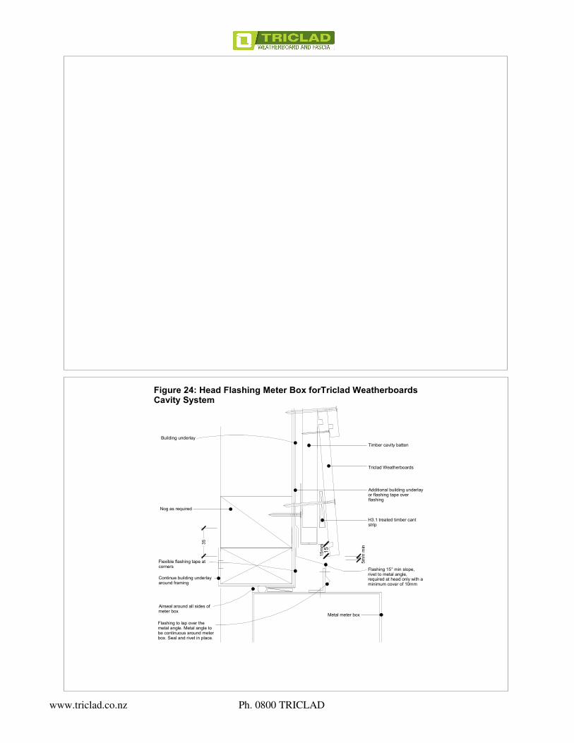
Figure 24: Head Flashing Meter Box forTriclad Weatherboards Cavity System
Building underlay
Timber cavity batten
Triclad Weatherboards
Additional building underlayor flashing tape overflashing
H3.1 treated timber cantstrip
Flashing 15° min slope,rivet to metal angle,required at head only with aminimum cover of 10mm
Metal meter box
Flashing to lap over themetal angle. Metal angle tobe continuous around meterbox. Seal and rivet in place.
Airseal around all sides ofmeter box
Continue building underlayaround framing
Flexible flashing tape atcorners
Nog as required
www.triclad.co.nz Ph. 0800 TRICLAD

10
Timber cavity batten
Triclad Weatherboards
Continuous sealantto metal angle
Metal meter box
Metal angle to becontinuous around meterbox. Seal and rivet inplace.
Flexible flashing tape atcorners
Airseal around all sides ofmeter box
Continue building underlayaround framing
Building underlay
Figure 25: Sill Flashing Meter Box forTriclad Weatherboards Cavity System
Figure 26: Jamb Flashing Meter Box forTriclad Weatherboards Cavity System
Triclad WeatherboardsLapped or Rustic
Timber cavity battens
Scriber
Line of head flashing over20mm past scriber
Seal against the meter box
Metal meter box
Building underlay
Continue buildingunderlay around framing
Airseal around all sides ofmeter box
Flexible flashing tape atcorners
Metal angle to becontinuous around meterbox. Seal and rivet in place.
www.triclad.co.nz Ph. 0800 TRICLAD

35
75
198
15
Figure 28: One Piece Apron Flashing Cavity System
flashing leg above base of
weatherboard
Refer to E2/AS1 Table 7
clear gap
When 50 year durability for flashing is required refer Table 20 NZBCE2/AS1 document.
*
*
Refer Figure 7 and Table 7 of E2/AS1 document
15mm
Building underlay
Flashing tape or extra layer ofbuilding wrap over flashing
Timber cavity batten
Triclad Lapped weatherboard
Flashing
H3 treated timber cant strip
uPVC vent strip
Edge of flashing dresseddown or notched
Roof underlay continued upbehind flashing
Selected roofing with stopend
Roof framing
Nog as required
www.triclad.co.nz Ph. 0800 TRICLAD

50
120
6
50mm
Ground level
6mm framingoverhang
150mm min to perm
anent paving or 225mm
min to unpaved ground to clause 9.1.3 of
E2/AS1
D.P.C.
Bottom plate
Concrete slab / footing
25mm wide cant strip. H3.1treated timber. Thickness to suitselected weatherboard.
Building underlay
Figure 31: Direct Fix Base for Horizontal Lapped Weatherboards Concrete Slab
50
50
25mm wide cant strip. H3.1treated timber. Thickness tosuit selected weatherboard.
Triclad Lapped HorizontalWeatherboards
Building underlay
uPVC vent strip with1000mm{² }of opening perlineal metre. Mitre at corners.Keep clear of debris
H3.2 boundary joists, if H1.2 joistsused the cladding is to drop 50mmbelow bottom edge of joists
Bottom plate
D.P.C.
Figure 32: Direct Fix Base for Horizontal Lapped Weatherboards Timber Floor
www.triclad.co.nz Ph. 0800 TRICLAD

50
50
Figure 34: External Boxed for Triclad Lapped Weatherboards Direct Fix System
40x12 scriber cut to fit. Sealant toback of scriber and face ofweatherboard joint
50x50 corner flashing
Min. ex 25mm cover boards with6x6mm weathergrooves
40x12 scriber cut to fit. Sealant to back ofscriber and face of weatherboard joint
Triclad horizontal lapped Weatherboards
Building wrap
Vertical Batten
Note: Corner battens shall be sized to provide 50mm minimum cover over cladding
Metal Corner Soaker over
Figure 35: External Mitred Corner Triclad Lapped Weatherboards Direct Fix System
butt finish boards
50x50mm corner flashing overbuilding wrap
Building wrap
Note: Corner battens shall be sized to provide 50mm minimum cover over cladding
www.triclad.co.nz Ph. 0800 TRICLAD

Figure 38: Internal Corners for Triclad Lapped Weatherboards Direct Fix System
50x50mm corner flashingover building wrap
Building wrap
Triclad horizontal lappedWeatherboards butt into corner
www.triclad.co.nz Ph. 0800 TRICLAD

12
33
5
Triclad horizontal lapped Weatherboardblock behind as necessary for support
Additional Building wrap or flashing tapelap over head flashing(placed over building wrap)
Formed Aluminium Head Flashing
Figure 42: Head Flashing for Triclad Lapped Weatherboards Direct Fix System
Stopends to headflashing
Building wrap dressed into openingwith flexible flashing tape installed overwrap to corners at head
Air seal
Packers
10
5 35
Triclad horizontal lapped Weatherboardblock behind as necessary for support
Figure 43: Sill Flashing for Triclad Lapped Weatherboards Direct Fix System
Air seal
Packers
Horizontal batten under windowas necessary to suit proflie
10mm min. joinery cover to flashing
Building wrap and flexibleflashing tape
5mm gap without seal
Sill flashing with 5° min fall andhem to back edge
Line of 10mm min upstand at bothends of sill flashing
Sill flashing to line with back ofwindow frame
Note: 1. Window profile to be selected to achieve cover shown indetails2. Architraves are shown for consistency only, detail may beused with rebateted line3. Make allowance between packer at sills for support brackets for large windows. Such brackets require specific design, andshall be supplied by the window manufacturer.
35mm min. flashing cover
www.triclad.co.nz Ph. 0800 TRICLAD

20
40x12 Scriber sealed to Weatherboards
Figure 44: Jamb Flashing for Triclad Lapped Weatherboards Direct Fix System
Building wrap dressed into opening withflexible flashing tape installed over wrap
Air seal
Packers
Line of sill flashing under
Line of sill flashing upstand
Line of head flashing over
Note: 1. Window profile to be selected to achieve cover shown indetails2. Architraves are shown for consistency only, detail may beused with rebated line3. Make allowance between packer at sills for support bracketsfor large windows. Such brackets require specific design, andshall be supplied by the window manufacturer.
www.triclad.co.nz Ph. 0800 TRICLAD

5
33
15
Triclad rusticated Weatherboard
Formed Aluminium Head Flashing
Figure 45: Head Flashing for Triclad Rustic Weatherboards Direct Fix System
Additional building wrap from overlapabove lapped over flashing
Stopends to head flashing
Building wrap dressed into openingwith flexible flashing tape installed overwrap to corners at head
Air seal
Packers
Note: 1. Window profile to be selected to achieve cover shown indetails2. Architraves are shown for consistency only, detail may beused with rebated line3. Make allowance between packer at sills for support bracketsfor large windows. Such brackets require specific design, andshall be supplied by the window manufacturer.
10
35
Figure 46: Sill Flashing for Triclad Rustic Weatherboards Direct Fix System
Chamfer trimmer plateas required to suit flashing
10mm min. joinery cover to flashing
Building wrap and flexible flashing tape
5mm gap without seal
Sill flashing with 5° min fall andhem to back edge
Line of 10mm min upstand at bothends of sill flashing
Sill flashing to line with back ofwindow frame
Air seal
Packers
Note: 1. Window profile to be selected to achieve cover shown in details2. Architraves are shown for consistency only, detail may be usedwith rebated line3. Make allowance between packer at sills for support brackets forlarge windows. Such brackets require specific design, and shall besupplied by the window manufacturer.
35mm min. flashing cover
www.triclad.co.nz Ph. 0800 TRICLAD

20
31
J mould for weatherboards tosit into, ensure placement isover sill flashing
Figure 30: Jamb Flashing for Triclad Rustic Weatherboards Direct Fix System
Building wrap dressed into opening with flexibleflashing tape installed over wrap to corners at head
Air seal
Packers
Line of sill flashing under
Line of head flashing above
Sealant to fillets
Note: 1. Window profile to be selected to achieve cover shown indetails2. Architraves are shown for consistency only, detail may beused with rebated line3. Make allowance between packer at sills for support bracketsfor large windows. Such brackets require specific design, andshall be supplied by the window manufacturer.
www.triclad.co.nz Ph. 0800 TRICLAD