PGS 1 to 19forpeter chapman - Rulmeca Corp
108
Transcript of PGS 1 to 19forpeter chapman - Rulmeca Corp


RULMECA FAA GmbH, Aschersleben, Germany - Rulmeca Motorized Pulley Manufacturing Facility.
CNC gear shaping CNC gear hobbing system Motor construction
Administrative offices Plate rolling system for large diameter shells
Large Motorized Pulley shipment for North America Motor and gearbox assembly

www.rulmecacorp.com TC101: 03/071
Rulmeca Motorized Pulley Cut-away View and Summary of Key Benefits................................................................................coverRulmeca Motorized Pulleys Application Photos........................................................................................................................ coverRulmeca FAA GmbH Manufacturing Facility Photos ............................................................................. .................................. coverTable of Contents ................................................................................................................................................................... .. 1Rulmeca Motorized Pulleys - Introduction..................................................................................................................................... 2Features and Benefits of Rulmeca Motorized Pulleys ............................................................................................................. 3Rulmeca Motorized Pulleys - General Description ....................................................................................................................... 4
• Motorized Pulley Highlight: “Mounting Orientations” ............................................................................................................. 5• Motorized Pulley Highlight: “Dual Drive Concept” ................................................................................................................. 6
Ordering Information ....................................................................................................................................................................... 7Model 138E (5.45” diameter) specifications ............................................................................................................................. 8-13Model 165E (6.49” diameter) specifications ............................................................................................................................. 14-19Model 220M & 220H (8.50” diameter) specifications .............................................................................................................. 20-28
• Motorized Pulley Highlight: “Compact Drives” ....................................................................................................................... 29Model 320L, 320M & 320H (12.64” diameter) specifications.................................................................................................. 30-38
• Motorized Pulley Highlight: “Tail Drives” ................................................................................................................................ 39Model 400L, 400M & 400H (15.91” diameter) specifications.................................................................................................. 40-48
• Motorized Pulley Highlight: “Hopper Feeder Drives” ......................................................................................................... 49Model 500L, 500M & 500H (19.72” diameter) specifications.................................................................................................. 50-58
• Motorized Pulley Highlight: “Bucket Wheel Excavators & Reclaimers”................................................................................ 59Model 630M & 630H (24.80” diameter) specifications ............................................................................................................ 60-63Model 800M & 800H (31.50” diameter) specifications ............................................................................................................ 64-67Part Lists & Sectional Drawings - 500H, 630M, 630H, 800M & 800H......................................................................................... 68-69
• Motorized Pulley Highlight: “Mechanical Backstops” ............................................................................................................ 70• Motorized Pulley Highlight: “Internal and External Brakes” .................................................................................................. 71
Special Environmental Conditions.................................................................................................................................................. 72-73Bulk Handling Engineering Principles............................................................................................................................................ 74Application Worksheet .................................................................................................................................................................... 75Technical Precautions for Design, Installation and Maintenance................................................................................................. 76-86
• Motorized Pulley Highlight: “Variable Frequency Drives”...................................................................................................... 87International Protection - IP ratings................................................................................................................................................ 88
• Motorized Pulley Highlight: “Lagging Options” ...................................................................................................................... 89Oil Quantities and Oil Types........................................................................................................................................................... 90-91Electrical Connection Diagrams - 138E - 800H........................................................................................................................92-100
Summary of Optional Extras .......................................................................................................................................................... coverInternational Directory..................................................................................................................................................................... cover
Table of Contents

www.rulmecacorp.com TC101: 03/072
The Rulmeca Motorized Pulleys present-ed in this catalogue have a long historyto tell. It goes back to the 1950’s, whenthe product was developed in Germanyand Denmark.
Eventually, through a merging processthe German Förder und AntriebstechnikAschersleben GmbH and the DanishJohn Kirkegaard Maskinfabrik A/Sbecame partners in the Interroll Group.
From the early 1990’s the manufacturingof all Interroll’s BULK Motorized Pulleyswere centralized in Aschersleben, Ger-many.
In July 2003 Rulli Rulmeca S.p.A. pur-chased the production facility in Ascher-sleben, Germany, where Motorized Pul-leys have been developed and producedfor almost half a century, along with theentire BULK Business Unit.
Today this plant, renamed RulmecaFAA GmbH, will continue the JOKI tradition for quality and reliability underthe Rulmeca brand.
Thanks to this long history Rulmeca is avery experienced manufacturer of BULKMotorized Pulleys, offering the world’slargest product range.
www.rulmecacorp.comwww.precismeca.ab.ca
Rulmeca Motorized Pulleys: a new name with deep roots

Purpose-built designThe Rulmeca Motorized Pulley has beenspecifically designed for belt conveyors.
Hermetically SealedThe motor, gearbox and bearings arehermetically sealed inside a steel shell.Therefore they are unlikely to fail due toharmful environmental conditions suchas water, dust, grit, chemicals, grease,oil, etc.
Space saving designBecause the drive unit and the bearingsare mounted inside the Motorized Pulleyshell, it requires much less room than anexposed drive. No need for costly extraslike chains, v-belts, couplings, bearings,support structure and special guarding.
SafetyThe Rulmeca Motorized Pulley is one ofthe safest drives available because themotor is completely enclosed and theexternal shafts are always stationary.The only moving external parts are theMotorized Pulley shell and bearing hous-ings.
Low purchasing and installation costThe Rulmeca Motorized Pulley is quiteoften less expensive than exposeddrives because it has fewer parts. There-fore less conveyor design time and partspurchasing costs. It is also much quickerand easier to install - certainly less thana quarter of the time taken to fit anexposed system.
Low maintenance costThe end user also benefits from the Rul-meca Motorized Pulley, because itrequires no maintenance other than therecommended oil change every 10,000operating hours and oil seal change
Features and Benefits of Rulmeca Motorized Pulleysevery 30,000 operating hours. In otherwords, almost 5 years between oilchanges based on an 8-hour/day work-ing week. Synthetic oil can be specifiedto extend the oil service life up to 30,000operating hours.
EfficiencyThe Rulmeca Motorized Pulley usuallyhas a much higher efficiency from elec-trical motor to shell (Pulley face) thanexposed drives, because it has fewerfrictional losses. Therefore, efficienciesof up to 97% can be achieved.
CleanlinessBecause the Rulmeca Motorized Pulleyis hermetically sealed it cannot contami-nate any conveying materials such asfood, electrical components, plastics andother materials that must be kept per-fectly clean during handling.
Aesthetic appearanceIf installed correctly the Rulmeca Motor-ized Pulley always looks good. Due to itscompact size and smooth lines, theMotorized Pulley is out of sight, because itis hidden within the conveyor frame.
Thermal protectionAll three phase Rulmeca Motorized Pul-leys are protected by our thermal protec-tion switches. These heat-sensitiveswitches are built into the motor wind-ings to protect the motor from overheat-ing. The thermal protectors must be con-nected to a normally closed control cir-cuit in order to protect the motor.
Weight saving and distributionThe Rulmeca Motorized Pulley is oftenlighter than exposed drives. It is possi-ble to reduce the weight and cost of theconveyor structure, because the convey-
or drive weight is evenly distributed with-in the conveyor frame.
Variable frequency drive All Rulmeca Motorized Pulleys with 3phase motors are easily controlled byvariable frequency drives working in the12 Hz to 66 Hz frequency range. SeeTechnical Precautions in the catalogue.
Fewer parts A Rulmeca Motorized Pulley consists ofthe Motorized Pulley and two fixingbrackets! Exposed drives can require upto eight or more separate components,most of which have to be purchasedfrom different suppliers or custom manu-factured.
Low noiseThanks to the totally sealed enclosureand high quality gears the RulmecaMotorized Pulley runs almost at a whis-per – a very important fact in today’smodern factory environments.
The Rulmeca Motorized Pulley – theideal drive unit for conveyors “Fit itand forget it!”
www.rulmecacorp.com TC101: 03/073

www.rulmecacorp.com TC101: 03/074
The Rulmeca Motorized Pulley was firstproduced in 1953 specifically for use onconveyor belt applications.
Until recently it was known as the JOKIMotorized Pulley or JOKI drum motor.
The objective was to produce a compact,hermetically sealed, highly efficient con-veyor drive unit that would be unaffectedby dust, water, oil, grease or other harm-ful substances. A Motorized Pulley thatwould be quick and simple to install andrequire virtually no maintenance.
The Rulmeca Motorized Pulley achievedthis objective and today is considered tobe one of the most reliable, effective andsafe conveyor drive systems availablethroughout the world.
The Rulmeca Motorized Pulley is a high-ly efficient geared motor drive, which ishermetically sealed within a steel cylin-drical shell.
The shell, which is normally crowned toensure belt tracking, is fitted with bearinghousings incorporating precision bear-ings and double lipped oils seals androtates on a pair of fixed shafts.
The motor stator is fixed to the shaftsand the motor winding cables passthrough one of the shafts, eliminating theneed for slip rings and brushes.
General DescriptionThe squirrel cage induction motor, man-ufactured in steel laminate, is machinedconcentric to high tolerances anddesigned to give 200% starting torque for3 phase versions.
The rotor pinion is coupled directly to thegearbox.
The gearbox transmits torque to the shellthrough a geared rim and allows very lit-tle frictional torque loss.
The Motorized Pulley is filled with oil,which acts as a lubricant and coolant.Heat is dissipated through the shell andconveyor belt.
All vital parts are CNC machined.
The Rulmeca Motorized Pulley is sup-plied as standard with:• Machined mild steel crowned shell.• Electric motor manufactured in accor-
dance with IEC 34-1 (EN60034-1),(VDE 0530).
• Class F insulation according to IEC 34-1 (EN60034-1), (VDE 0530).
• Most international voltages. • Standard voltages supplied with +/-
10% tolerance in accordance with IEC38.
• Factory oil filled and tested.• Degree of protect ion IP66/67
(EN60034-5).
Rulmeca Motorized Pulleys are manu-factured according to the Council Direc-tives of the European Communities.
The CE-marking is according to Direc-tive 73/23/EEC relating to electricalequipment and according to Directive89/336EEC relating to electrical magnet-ic compatibility and amendments.

www.rulmecacorp.com TC101: 03/075
Head Pulley Drive (Above Horizontal Mounting Surface)Typical “head pulley drive position” on sinter conveyor at Chicago area steelmill. Two bolts secure each mounting bracket to top of the horizontal struc-tural surface. This model 630M (24.8” diameter) 30 HP Motorized Pulleydrives the 48” wide belt at 384 FPM. Note that two cables enter terminal boxthrough separate fittings. Power cable connects pulley’s motor to460V/3ph/60 Hz plant supply and control cable connects pulley’s internalthermal protection switches to 115V/1ph/60 Hz normally-closed control cir-cuit. Note that this 2,000 lb Motorized Pulley is fitted with lifting lugs. Photoalso shows jacking screw used to facilitate pulley alignment.
Technical Precaution: Always mount motorized pulley with “UP” directionoriented according to installation instructions (see page 82.)
Center Pulley Drive (On Fixed Vertical Mounting Surface)Photo shows one of two 150 HP Rulmeca Motorized Pulleys in “center driveposition” on two mile long overland conveyor at Lafarge’s Mountsorrel Quar-ry. Transferring granite on the 48” wide belt at various rates up to 2,000TPH, the two Motorized Pulleys are driven by synchronized ABB variablefrequency drives. Two bolts (with locking nuts) secure each mounting brack-et to side of the vertical structural surface. The two drives are mountedbeneath the conveyor belt, 50 feet apart and have an automatic belt take-upsystem operating between them. The Motorized Pulley’s compactness sim-plified the 2006 system upgrade.
Tail Pulley Drive (On Movable Vertical Mounting Surface)TAKRAF mobile crusher uses model 630M 50 HP Rulmeca Motorized Pul-ley in “tail drive position” to move limestone on 100 foot long cantilevereddischarge conveyor at German limestone quarry. Choosing tail rather thanhead drive position enabled designers to avoid suspending the 2,000 lb con-veyor drive unit at the tip of the cantilever. Compact Motorized Pulley easi-ly fit within the expanding bracket-type jacking screw belt take-up.
Technical Precaution: When mounting a motorized pulley in a screw take-up always make sure that pulley centerline is perpendicular to belt center-line to avoid overstressing internal bearings. Also make sure to provide a“festoon loop” in the power cord so that Motorized Pulley will have enoughtravel distance to accommodate normal belt stretch.
Center Pulley Drive (Below Horizontal Mounting Surface)Located in “center drive position” beneath bucket wheel reclaimer boomconveyor at Lake Superior taconite ship loading facility, model 800H 120 HPMotorized Pulley drives boom conveyor belt at 768 FPM. Two bolts (withlocking nuts) secure each mounting bracket to bottom of the horizontalstructural surface. Note two jib keys used to transfer drive torque from shaftto mounting bracket. The 54” wide boom conveyor transfers taconite pelletsfrom boom tip receiving chute to the cantilevered tail conveyor.
Technical Precaution: Always mount motorized pulleys so that 100% of beltforce presses against shoulder or base of mounting brackets (see page 82-83.)
Motorized PulleyMounting Orientations

www.rulmecacorp.com TC101: 03/076
Motorized PulleysDual Drive Concept
Bucket Wheel Reclaimer for taconite pelletsLocated in “center drive position” beneath a 4,000 TPH bucket wheelreclaimer tail conveyor at Lake Superior taconite ship loading facility, twomodel 800H 120 HP Motorized Pulleys drive discharge belt at 768 FPM.Since the 2004 reclaimer upgrade, each Motorized Pulley is powered by460V/3ph/60 Hz directly by the on-board diesel electric generator. Motorsynchronization was not necessary on either this reclaimer or its two sistermachines at the terminal.
Technical Precaution: Always mount motorized pulley with “UP” directionoriented according to installation instructions.
Suspended Construction Conveyor for wet concreteOne of four 150 foot long “dual drive” conveyors suspended from construc-tion cranes to pour wet concrete during Sesam River Dam construction inSoutheast Asia. During the five year project each conveyor was driven atthe head and tail by a model 800H 50 HP Rulmeca Motorized Pulley.
Overland Conveyor for graniteOne of two 150 HP Rulmeca Motorized Pulleys on two mile long overlandconveyor at Lafarge’s Mountsorrel Quarry in “center drive position.” The twoMotorized Pulleys are driven by synchronized ABB variable frequencydrives (VFDs), transferring granite on the 48” wide belt at various rates upto 2,000 TPH. The VFDs: (1.) provide a “soft start” feature, (2.) enable thetwo drives to “talk” and keep rotor speeds synchronized, and (3.) conservepower by linking to load sensors and optimizing belt speed according tomeasured conveyor throughput.
Technical Precaution: When using a VFD always restrict frequencies tobetween 12 Hz to 66 Hz and install a filter on the VFD output if it is locatedmore than 30 feet from the Motorized Pulley (see page 86.)
Reversing Shuttle Conveyor for crushed graniteOne of two 31.5” diameter 50 HP Motorized Pulleys, one on north end andone on south end, driving reversing shuttle conveyor at Lafarge’s Mountsor-rel granite quarry since 1998. Photo shows stone discharging from 600FPM belt at 2,500 TPH. Changing from a “single drive” to a “dual drive”arrangement can reduce slack-side belt tension (T2) to 20%. This willreduce maximum belt tension (T1) and can significantly extend conveyor beltlife because it provides 360 degrees of belt wrap around pulleys (180degrees per Motorized Pulley), without the use of “dirty side” snub pulleys.
Technical Precaution: When using Motorized Pulleys in reversing applica-tion, always bring conveyor to complete stop before starting belt in oppositedirection (see page 84-85.)
www.rulmecacorp.com TC101: 03/077
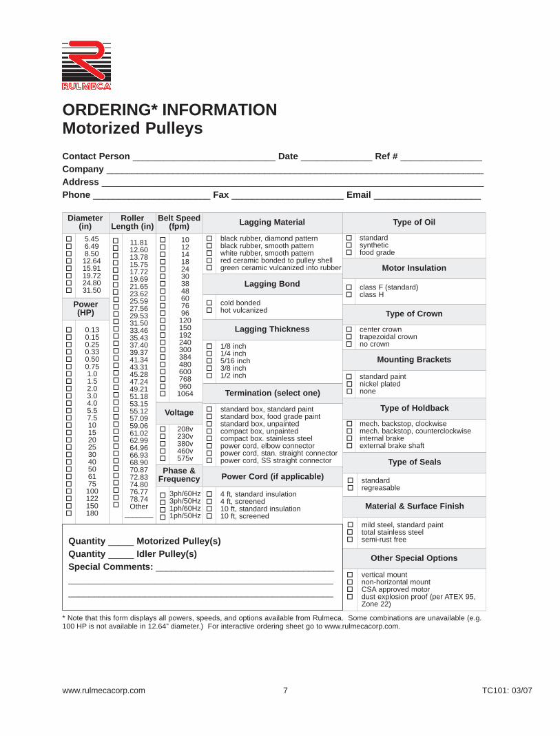
ORDERING* INFORMATIONMotorized Pulleys
Belt Speed (fpm)
1012141824303848607696
120150192240300384480600768960
1064
Lagging Material
black rubber, diamond patternblack rubber, smooth patternwhite rubber, smooth patternred ceramic bonded to pulley shellgreen ceramic vulcanized into rubber
Lagging Bond
cold bondedhot vulcanized
Lagging Thickness
1/8 inch1/4 inch5/16 inch3/8 inch1/2 inch
Type of Oil
standardsyntheticfood grade
Motor Insulation
class F (standard)class H
Type of Crown
center crowntrapezoidal crownno crown
Mounting Brackets
standard paintnickel platednone
Type of Holdback
mech. backstop, clockwisemech. backstop, counterclockwiseinternal brakeexternal brake shaft
Type of Seals
standardregreasable
Material & Surface Finish
mild steel, standard painttotal stainless steelsemi-rust free
Other Special Options
vertical mountnon-horizontal mountCSA approved motordust explosion proof (per ATEX 95,Zone 22)
Diameter(in)
5.456.498.50
12.6415.9119.7224.8031.50
Voltage
208v230v380v460v575v
Phase &Frequency
3ph/60Hz3ph/50Hz1ph/60Hz1ph/50Hz
RollerLength (in)
11.8112.6013.7815.7517.7219.6921.6523.6225.5927.5629.5331.5033.4635.4337.4039.3741.3443.3145.2847.2449.2151.1853.1555.1257.0959.0661.0262.9964.9666.9368.9070.8772.8374.8076.7778.74Other
_______
Power (HP)
0.130.150.250.330.500.751.01.52.03.04.05.57.5101520253040506175
100122150180
Termination (select one)
standard box, standard paintstandard box, food grade paintstandard box, unpainted compact box, unpaintedcompact box. stainless steelpower cord, elbow connectorpower cord, stan. straight connectorpower cord, SS straight connector
Power Cord (if applicable)
4 ft, standard insulation4 ft, screened10 ft, standard insulation10 ft, screened
Contact Person ____________________________ Date ______________ Ref # ________________Company __________________________________________________________________________ Address ___________________________________________________________________________Phone _______________________ Fax ______________________ Email _____________________
Quantity _____ Motorized Pulley(s)Quantity _____ Idler Pulley(s)Special Comments: ___________________________________________________________________________________________________________________________________________
* Note that this form displays all powers, speeds, and options available from Rulmeca. Some combinations are unavailable (e.g.100 HP is not available in 12.64” diameter.) For interactive ordering sheet go to www.rulmecacorp.com.

www.rulmecacorp.com TC101: 03/078
Motorized Pulley 138E, Ø 5.45 in. (138 mm)Motorized Pulley 138E, withmachined helical gearbox, performswith a gearbox efficiency of 95% ofnominal power, in a compact diame-ter of 5.45 inches. With a minimumroller length (RL) of 11.81” and pow-ers ranging from 0.13 to 1.0 HP, thisMotorized Pulley is suitable for mostsmall diameter applications. Theseinclude:
• Light agricultural conveyors• Light C & D debris conveyors• Mobile and portable conveyors
Motorized Pulley 138E features astandard enclosure class of IP66/67and is also available in stainlesssteel for wash down applications.
STANDARD SPECIFICATIONof Motorized Pulley
• Crowned mild steel 5.45” shell treatedwith anti-rust wax
• Die cast aluminum bearing housing• Mild steel shaft treated with anti-rust
wax• Die cast lightweight aluminum gearbox
housing• Sealing system – degree of protection
IP66/67 (EN60034-5.) See page 88.• Compact die cast aluminum terminal
box with WAGO connectors• Voltage: All common voltages avail-
able. Please specify.• Three phase induction motor• One out of two oil plugs is fitted with a
magnet to filter the oil. • Motor winding insulation class F• Dynamically balanced rotor • Oil change recommended every
10,000 operational hours • Maximum RL 70.87”• Non standard RL lengths available• Single phase is available in 0.33, 0.50,
and 0.75 HP, supplied with a runningcapacitor
• To be used in the horizontal positiononly.
STAINLESS STEELoptions
TS7N• Stainless steel shell – AISI 304 range• Stainless steel shafts – AISI 303 range• Stainless steel covered aluminum bear-
ing housings – AISI 304 range• Stainless steel oil plugs with magnet –
AISI 304 range• Compact stainless steel terminal box –
AISI 304 range• Alternatively, straight stainless steel
connector – AISI 303 range with powercord.
• Regreasable stainless steel seals –AISI 303 range
• Degree of protection IP66/67 (EN60034-5.) See page 88.
• FDA & USDA food grade grease• Option: FDA & USDA food grade rec-
ognized oil.• Special mounting brackets are avail-
able
Please note:
• Noise-sensitive Areas: High speed 2-pole motors can cause higher noiselevels and are not recommended fornoise-sensitive areas
• Technical Precautions for Design,Installation, and Maintenance: pages76-86
• Environmental Considerations: page72
• Optional Extras: pg 9 and back cover• Electrical Connection Diagrams:
pages 94-96.

www.rulmecacorp.com TC101: 03/079
OPTIONAL EXTRASMotorized Pulley 138E
Specification Availability
Total stainless steel option AISI 304 range TS7N with regreasable labyrinth seals x
Food grade oil & grease - FDA & USDA recognized x
Dust explosion proof Motorized Pulleys - ATEX 95 - Zone 22 - for applications handling dusty grain etc. According to European Directive 94/9/EC. x
Total acid resistant stainless steel option - AISI 316 x
Black rubber lagging - Standard specifications (See page 80.)1/8” smooth lagging - Hardness 60 ±5 Shore A o
White smooth rubber lagging (FDA). Oil, fat & grease resistant o
Special lagging (e.g. hot vulcanized) o
Electromagnetic brake Min. RL increases by 1.97” x
Mechanical backstop Min. RL does not increase with backstop option x
Modified for vertical mounting o
Modified for mounting between 5° and 90° (e.g. for magnetic separators) o
Insulation class F with standard oil: (Allowable ambient temperature: -13°F/+104°F) Std.
Insulation class H with synthetic oil: (Allowable ambient temperature: -13°F/+120°F) x
Special motors for applications with no belt contact o
Low noise drives for noise sensitive areas x
Parallel shell x
Thermal protector Std.
IP66/67 Compact unpainted aluminum terminal box Std.
IP66/67 Compact stainless steel terminal box- AISI 304 or 316 range x
Straight or elbow connector with standard power cord x
Straight connector with screened power cord (See page 86 for VFD precautions) x
Straight connector with standard power cord (Stainless steel in AISI 304 range) x
Voltage: single voltage (460) stator (Y winding) wired for 460v/3ph/60 Hz at terminal box Std.
single voltage (230) stator (YY winding) wired for 230v/3ph/60 Hz at terminal box x
2 speed motors x
Special voltage motors x
Single phase motors o
CSA approved motors x
x = Optional extra’so = An option with certain limitations. Please refer to Technical precautions pages 72-86Std. = Fitted as standard

www.rulmecacorp.com TC101: 03/0710
138E
Cast ironpainted
KL30
S2YAKL
7.09 1.18 0.79 3.39 2.24 0.43 0.67 0.47 0.95 4.33 1.75 2.83 1.54Cast iron Ni plated S2YAKMStainless
steel S3KL33
Motorized Pulley with Terminal box
Motorized Pulley with cablestraight connector
Elbow connector(not for TS7N)
Idler Pulley3 TS7N version
Motorized Pulley or idler Pulley (UT) Compact terminal Straight Elbowbox connector connector
A B C D E F G H K W L M N N1 U V R S TModel in in in in in in in in in in in in in in in in in in in
138E 5.45 5.39 0.93 1.18 2.13 0.79 0.20 0.65 0.93 – 1.61 0.95 3.74 0.55 0.14 0.77 0.79 1.89 0.47UT138E 5.45 5.45 0.93 1.18 2.13 0.79 0.53 0.65 – 1.42
Motorized Pulley 138E, Ø 5.45 in. (138 mm)
1 A dimension is outer diameter of unlagged pulley shell at pulley centerline.2 B dimension is outer diameter of unlagged pulley shell at each end of shell.3 Idler pulley shown is non-crowned TS7N version with regreasable seals.
Mounting brackets
ModelAin
Din
Fin
Iin
Kin
Sin
Tin
Vin
W1in
Xin
Zin
Z1in lbs
MotorizedPulleys
Material BracketSize
PartNumber
Dimensions Weight

www.rulmecacorp.com TC101: 03/0711
Motorized Pulley 138E, Ø 5.45 in. (138 mm) 60 HzMotor
No.Gear
StagesModel
Nominal beltspeed1 atFull Load
60 Hzfpm
Actual beltspeed1 atFull Load
60 Hzfpm
BeltPull2
lbs
Max.RadialLoad3
T1 + T2lbs
Min.RL
in
RL Dimension inches (RLmax = 70.87”)Weight in lbs5 Type
ofBracket
Power
HP
No.of
Poles 11.81 12.60 13.78 15.75 17.72 19.69 21.65 23.62 25.59longerthan
25.59
0.13 123 138E
101214
101416
397318263
1,066 11.81 32 33 34 37 40 42 44 46 49SeeFoot-note4
KL30S2YAKL
2 138E 2430
2428
178152
0.25 83 138E
182430
202429
384309254
2 138E 3848
4451
172147
0.33 63 138E
243038
253138
404325265
2 138E486076
556582
182155124
0.50 4
3 138E384860
384758
412331273
2 138E7696
120150
8598
123150
185158126104
0.75 2
3 138E
48607696
120
55647493113
416363310249205
2 138E150192240300
166196244296
1391199578
1.04 3 138E
7696
120150
88104129157
357304244201 12.60 - 34 37 41 43 45 47 49 53
2 2 138E192240300
207258314
152122100
Idler Pulley Model UT138E 1,066 11.81 15 16 18 21 23 25 27 29 32SeeFoot-note4
KL30S2YAKL
1 Use “nominal belt speed” to specify pulley. “Actual belt speed” is presented (for pulley lagged with 1/8” thick rubber) to assist with process design calculations.See Technical Precautions page 77. Note that “actual belt speed” decreases when lagging is not used due to decreased pulley diameter.
2 Belt pull value allows for gearbox loss.3 Pulley must not be subjected to radial load exceeding “Maximum radial load” defined above. See “Belt Tension” section in Technical Precautions, page 78.4 Additional Motorized Pulley and Idler Pulley weight, specified per Roller Length:
25.59”< RL < 39.37” Wt = 1.3 lbs/inch39.37”< RL < 59.06” Wt = 1.5 lbs/inch59.06”< RL < 70.87” Wt = 2.0 lbs/inch
5 All weights shown above are for pulleys with 1/8” thick rubber lagging. To calculate unlagged pulley weight subtract 0.1 lbs/in of Roller Length from above.

www.rulmecacorp.com TC101: 03/0712
1 Front shaft3 Rear flange5 Bearing housing complete with
geared rim7 Bearing housing complete8 Gearbox
10 Terminal box – bottom part11 Terminal box cover12 Shell16 Rear shaft19 Input wheel20 Output pinion22 Geared rim23 Intermediate pinion shaft24 Intermediate wheel
Pos. Description Pos. Description Pos. Description
Motorized Pulley 138E, Ø 5.45 in. (138 mm)Spare parts list and sectional drawings
31 Labyrinth seal cover53 Nipple (terminal box53.1 Cable seal nipple (cable option)55 Spacer bushing56 Spacer bushing63 Ball bearing64 Needle bearing65–70 Ball bearing71 Inner race74 Locking ring84 Locking ring86 Locking ring93 Elbow or straight connector
102 Screw103 Screw
110 Screw111 Screw113 Screw 114 Socket set screw115 Oil plug with magnet126 Key127 Key131 Key132 Key136 O-ring/Rubber seal138 Rubber seal139 Grease nipple140 Deflection seal142 Double lip seal143 O-ring
2-stage gearbox

www.rulmecacorp.com TC101: 03/0713
145 Distance washer146 Washer148 Washer150 Electromagnetic brake 150.1 Friction disc156 Rectifier (not shown)
160 Oil plug161 O-ring163 O-ring167 Screw200 Rubber seal204 Rotor complete with pinion
208 Stainless steel cover – gearend
210 Fixing guard 223 Cable 226 Stator complete240 Distance ring
Pos. Description Pos. Description Pos. Description
Motorized Pulley 138E, Ø 5.45 in. (138 mm)Spare parts list and sectional drawings
TS7N with cable connection 3-stage gearbox Electromagnetic brake
TS7N with cable connection Elbow connector
www.rulmecacorp.com TC101: 03/0714
STANDARD SPECIFICATIONof Motorized Pulley
• Crowned mild steel 6.49” shell treatedwith anti-rust wax
• Die cast aluminum bearing housing• Mild steel shaft treated with anti-rust
wax• Die cast lightweight aluminum gearbox
housing• Sealing system – degree of protection
IP66/67 (EN60034-5.) See page 88.• Compact die cast aluminum terminal
box with WAGO connectors• Voltage: All common voltages avail-
able. Please specify.• Three phase induction motor• One out of two oil plugs is fitted with a
magnet to filter the oil. • Motor winding insulation class F• Dynamically balanced rotor • Oil change recommended every
10,000 operational hours • Maximum RL 70.87”• Non standard RL lengths available• Single phase is available in 0.50 and
1.50 HP, supplied with a running capac-itor
• To be used in the horizontal positiononly.
STAINLESS STEELoptions
TS7N• Stainless steel shell – AISI 304 range• Stainless steel shafts – AISI 303 range• Stainless steel covered aluminum bear-
ing housings – AISI 304 range• Stainless steel oil plugs with magnet –
AISI 304 range• Compact stainless steel terminal box –
AISI 304 range• Alternatively, straight stainless steel
connector – AISI 303 range with powercord.
• Regreasable stainless steel seals –AISI 303 range
• Degree of protection IP66/67 (EN60034-5.) See page 88.
• FDA & USDA food grade grease• Option: FDA & USDA food grade rec-
ognized oil.• Special mounting brackets are avail-
able.
Please note:
• Noise-sensitive Areas: High speed 2-pole motors can cause higher noiselevels and are not recommended fornoise-sensitive areas
• Technical Precautions for Design,Installation, and Maintenance: pages76-86
• Environmental Considerations: page72
• Optional Extras: pg 15 and back cover• Electrical Connection Diagrams:
pages 94-96.
Motorized Pulley 165E, Ø 6.49 in. (165 mm)Motorized Pulley 165E, withmachined helical gearbox, performswith a gearbox efficiency of 95% ofnominal power, in a compact diame-ter of 6.49 inches. With a minimumroller length (RL) of 13.78” and pow-ers ranging from 0.15 to 3.0 HP, thisMotorized Pulley is suitable for mostsmall diameter applications. Theseinclude:
• Light agricultural conveyors• Light C & D debris conveyors• Mobile and portable conveyors
Motorized Pulley 165E features astandard enclosure class of IP66/67and is also available in stainlesssteel for wash down applications.

www.rulmecacorp.com TC101: 03/0715
OPTIONAL EXTRASMotorized Pulley 165E
Specification Availability
x = Optional extra’so = An option with certain limitations. Please refer to Technical precautions pages 76-86!Std. = Fitted as standard
Total stainless steel option AISI 304 range TS7N with regreasable labyrinth seals x
Food grade oil & grease - FDA & USDA recognized x
Dust explosion proof Motorized Pulleys - ATEX 95 - Zone 22 - for applications handling dusty grain etc. According to European Directive 94/9/EC. x
Total acid resistant stainless steel option - AISI 316 x
Black rubber lagging - Standard specifications (See page 80.)1/8” smooth lagging - Hardness 60 ±5 Shore A o
White smooth rubber lagging (FDA). Oil, fat & grease resistant o
Special lagging (e.g. hot vulcanized) o
Electromagnetic brake Min. RL increases by 1.97” x
Mechanical backstop Min. RL does not increase with backstop option x
Modified for vertical mounting o
Modified for mounting between 5° and 90° (e.g. for magnetic separators) o
Insulation class F with standard oil: (Allowable ambient temperature: -13°F/+104°F) Std.
Insulation class H with synthetic oil: (Allowable ambient temperature: -13°F/+120°F) x
Special motors for applications with no belt contact o
Low noise drives for noise sensitive areas x
Parallel shell x
Thermal protector Std.
IP66/67 Compact unpainted aluminum terminal box Std.
IP66/67 Compact stainless steel terminal box- AISI 304 or 316 range x
Straight or elbow connector with standard power cord x
Straight connector with screened power cord (See page 86 for VFD precautions) x
Straight connector with standard power cord (Stainless steel in AISI 304 range) x
Voltage: single voltage (460) stator (Y winding) wired for 460v/3ph/60 Hz at terminal box Std.
single voltage (230) stator (YY winding) wired for 230v/3ph/60 Hz at terminal box x
2 speed motors x
Special voltage motors x
Single phase motors o
CSA approved motors x

www.rulmecacorp.com TC101: 03/0716
165E
Steel painted
KL41-HD
6YA0K
7.48 1.57 1.18 3.31 2.44 0.55 0.79 0.87 1.57 4.33 1.97 3.27 4.63Steel Ni plated 6YA0WStainless
steel 6YA0U
Mounting brackets
MotorizedPulleys
Material BracketSize
PartNumber
Dimensions Weight
Motorized Pulley with cablestraight connector
Elbow connector(not for TS7N)
Idler Pulley3 TS7N version
Motorized Pulley or idler Pulley (UT) Compact terminal Straight Elbowbox connector connector
A B C D E F G H K W L M N N1 U V R S TModel in in in in in in in in in in in in in in in in in in in
165E 6.49 6.44 1.71 1.57 3.15 1.18 0.39 0.85 1.63 – 1.61 0.95 3.74 0.55 0.16 1.06 0.79 1.89 0.47UT165E 6.49 6.49 1.71 1.57 2.95 1.18 0.65 0.85 – 1.81
Motorized Pulley 165E, Ø 6.49 in. (165 mm)Motorized Pulley with Terminal Box
1 A dimension is outer diameter of unlagged pulley shell at pulley centerline.2 B dimension is outer diameter of unlagged pulley shell at each end of shell.3 Idler pulley shown is non-crowned TS7N version with regreasable seals.
ModelAin
Din
Fin
Iin
Kin
Sin
Tin
Vin
W1in
Xin
Zin
Z1in lbs

www.rulmecacorp.com TC101: 03/0717
MotorNo.
GearStages
Model
Nominal beltspeed1 atFull Load
60 Hzfpm
Actual beltspeed1 atFull Load
60 Hzfpm
BeltPull2
lbs
Max.RadialLoad3
T1 + T2lbs
Min.RL
in
RL Dimension inches (RLmax = 70.87”)Weight in lbs5 Type
ofBracket
Power
HP
No.of
Poles 15.75 17.72 19.69 21.65 23.62 25.59 27.56 29.53 31.50longerthan
31.50
0.15 12 3 165E12141824
14162026
351288233177
2,097
15.75
66 69 72 76 78 80 83 87 90
SeeFoot-note4
KL41-HD6YA0K
0.50
6 3 165E 2430
2530
624512 68 71 75 78 80 83 86 89 92
4
3 165E3848607696
3748597798
414328265202160 64 67 70 73 76 78 81 84 88
2 165E120150192
123152199
12610278
240 251 62 1955
1.00 4
3 165E3848607696
3848597798
810664537409325 2097 70 74 77 80 82 84 88 91 94
2 165E120150192
123152199
256207158
240 251 125 1955
1.50
4 3 165E 60 66 730
2097
75 78 81 84 87 89 92 95 992
3 165E7696
120150192
8199
123161203
569467378288228
2 165E
240300
257318
180145 1955
384480600
416525646
1118874
1562
2.00 2
3 165E120150192
123161203
515393311
2097
77 80 83 87 89 91 94 98 1012 165E
240300
257318
246198 1955
384480600768
416525651787
15112010588
1562
3.00 2
3 165E120150192
132161192
717588466
2097
17.72 - 84 87 91 93 95 98 102 1053 165E 240300
250302
378314 1955
2 165E384480600768
417527648783
227180146121
1562
Motorized Pulley 165E, Ø 6.49 in. (165 mm) 60 Hz
1 Use “nominal belt speed” to specify pulley. “Actual belt speed” is presented (for pulley lagged with 1/8” thick rubber) to assist with process design calculations.See Technical Precautions page 77. Note that “actual belt speed” decreases when lagging is not used due to decreased pulley diameter.
2 Belt pull value allows for gearbox loss.3 Pulley must not be subjected to radial load exceeding “Maximum radial load” defined above. See “Belt Tension” section in Technical Precautions, page 78.4 Additional Motorized Pulley and Idler Pulley weight, specified per inch of Roller Length:
31.50”< RL < 45.28” Wt = 1.5 lbs/in45.28”< RL < 64.96” Wt = 2.1 lbs/in64.96”< RL < 70.87” Wt = 2.9 lbs/in
5 All weights shown above are for pulleys with 1/8” thick rubber lagging. To calculate unlagged pulley weight subtract 0.1 lbs/in of Roller Length from above.
Idler Pulley Model UT165E 2,097 15.75 33 35 39 43 45 47 50 54 58SeeFoot-note4
KL41-HD6YA0K

www.rulmecacorp.com TC101: 03/0718
Motorized Pulley 165E, Ø 6.49 in. (165 mm)Spare parts list and sectional drawings
53 Cable seal nipple (cable option)53.1 Nipple (terminal box)55 Spacer bushing56 Spacer bushing63 Ball bearing64 Needle bearing65–70 Ball bearing71 Inner race73 Locking ring74 Locking ring74 Locking ring81 Locking ring84 Locking ring85 Locking ring86 Locking ring93 Elbow or straight connector
102 Screw103 Screw110 Screw111 Screw112 Socket set screw113 Screw 114 Socket set screw115 Oil plug with magnet126 Key127 Key131 Key132 Key136 O-ring/Rubber seal138 Rubber seal
1 Front shaft3 Rear flange5 Bearing housing complete with
geared rim7 Bearing housing complete8 Gearbox
10 Terminal box – bottom part11 Terminal box cover12 Shell16 Rear shaft19 Input wheel20 Output pinion22 Geared rim23 Intermediate pinion shaft24 Intermediate wheel31 Labyrinth seal cover
2-stage gearbox
Pos. Description Pos. Description Pos. Description

www.rulmecacorp.com TC101: 03/0719
139 Grease nipple140 Deflection seal141 Double lip seal142 Double lip seal143 O-ring145 Distance washer146 Washer148 Washer150 Electromagnetic brake 150.1 Friction disc
156 Rectifier (not shown)160 Oil plug161 O-ring163 O-ring167 Screw200 Rubber seal204 Rotor complete with pinion206 Insulated sleeve for wire
protection208 Stainless steel cover – gear
end209 Stainless steel cover – oil plug
end210 Fixing guard 223 Cable 226 Stator complete240 Distance ring
TS7N with cable connection 3-stage gearbox Electromagnetic brake
TS7N Elbow connector
Motorized Pulley 165E, Ø 6.49 in. (165 mm)Spare parts list and sectional drawings
Pos. Description Pos. Description Pos. Description

20www.rulmecacorp.com TC101: 03/07
Motorized Pulley 220M & 220H, Ø 8.50 in. (216 mm)Our 8.50” diameter Motorized Pulleyrange offers two differentperformance levels for BULKapplications:
- M for Medium duty- H for Heavy duty
It is important to note the productdifferences and choose theappropriate pulley based onestimated belt tension (radial load.)See page 78. The actual radial loadmust be less than the maximumallowable radial load shown in thiscatalog.
Be aware of increased belt tensions required to drive multi-plythick heavy belts and/or larger beltwidths.
If the 8.50” diameter model is notstrong enough to resist estimatedbelt tension, then select 12.64”diameter model.
M for Medium dutyThe internal parts of 220M aredesigned to match irregular workingconditions in applications such asmobile crushing & screening, cement& concrete plants, mobile conveyorsand open stone & gravel pits.
H for Heavy dutyA reinforced 3-stage-gearboxprovides 220H with the necessarystrength needed for low speeds andhigh torque. 220H is popular in re-cycling (hand sorter conveyors),bunker discharge conveyors andwhere a combination of slow speedand high torque is required.
STANDARD SPECIFICATIONof Motorized Pulley
• Crowned mild steel 8.50” diameter steelshell treated with anti-rust wax
• Powder coated cast iron bearing hous-ings
• Mild steel shafts treated with anti-rustwax
• Shaft sealing system - degree of pro-tection IP66/67 (EN60034-5.) Seepage 88.
• Powder coated die cast aluminum ter-minal box
• 3-phase induction motors with thermalprotector
• Voltage: All common voltages avail-able. Please specify.
• Motor winding insulation Class F• Dynamically balanced rotor• One out of two oil plugs fitted with a
magnet to filter the oil• Oil change recommended every
10,000 operational hours• Minimum RL. Please refer to pages
23-24• Maximum RL – Please inquire• Non standard RL’s available• To be used in horizontal positions ± 5
degree only
Please note:
• Noise-sensitive Areas: High speed 2-pole motors can cause higher noiselevels and are not recommended fornoise-sensitive areas
• Technical Precautions for Design,Installation, and Maintenance: pages76-86
• Environmental Considerations: page72
• Optional Extras: pg 21 and back cover• Electrical Connection Diagrams:
pages 94-96.
STAINLESS STEELoptions
TS9N• Stainless steel shell – AISI 304 range• Stainless steel shafts – AISI 303/4
range• Stainless steel covered bearing hous-
ings – AISI 316 range• Stainless steel oil plugs – AISI 304
range – one out of two with magnet• Stainless steel exterior bolts – AISI 304
range• Regreasable labyrinth seals with
grease nipples in stainless steel– AISI 304 range
• Shaft sealing system – degree of pro-tection IP66/67 (EN60034-5).
TS10N• As TS9N, but without regreasable
labyrinth seals.
SEMI-RUST-FREE optionsTS11N• As TS9N, but with crowned mild steel
shell treated with anti-rust wax.
TS12N• As TS10N, but with crowned mild steel
shell treated with anti-rust wax.
Other Stainless Options: • FDA & USDA food grade recognized
oil and grease are not included in TS9Nto TS12N, but available on request
• Complete Motorized Pulleys in acidresistant stainless steel – AISI 316range – available on request.
• Special mounting brackets are avail-able
Electrical connection options:• Salt water resistant powder coated
aluminum terminal box with zinc platedexterior bolts
• Stainless steel terminal box – AISI 304range (max. 5.5 HP)
• Straight stainless steel connector withflying lead – AISI 304 range.
Please specify required TS-numberwhen ordering Stainless Steeloptions.

21www.rulmecacorp.com TC101: 03/07
OPTIONAL EXTRASMotorized Pulley 220M & 220H
Specification Availability
Total stainless steel option AISI 304 range TS9N with regreasable labyrinth seals xTotal stainless steel option AISI 304 range TS10N with standard seals xSemi-rust free option TS11N with regreasable labyrinth seals xSemi-rust free option TS12N with standard seals xRegreasable labyrinth seals xFood grade oil & grease - FDA & USDA recognized xDust explosion proof Motorized Pulleys - ATEX 95 - Zone 22 - for applications handling of dusty grain etc.According to European Directive 94/9/EC. xTotal acid resistant stainless steel option - AISI 316 xBlack rubber lagging - Standard specifications (See page 80.)
1/4” smooth lagging - Hardness 60 ±5 Shore A o1/4” diamond lagging - Hardness 60 ±5 Shore A o
White smooth rubber lagging (FDA). Oil, fat & grease resistant oSpecial lagging (e.g. hot vulcanized) oElectromagnetic brake Min. RL increases by 3.94” xMechanical backstop Min. RL does not increase with backstop option xModified for vertical mounting oModified for mounting between 5° and 90° (e.g. for magnetic separators) oInsulation class F with standard oil: (Allowable ambient temperature -13°F/+104°F) Std.Insulation class H with synthetic oil: (Allowable ambient temperature -13°F/+120°F) xSpecial motors for applications with no belt contact oLow noise drives for noise sensitive areas xParallel shell (i.e. no crown) xThermal protector Std.IP66/67 Yellow powder coated aluminum terminal box Std.IP66/67 Gray powder coated aluminum terminal box (food grade approved) xIP66/67 Compact powder coated aluminum terminal box (food grade approved) < 5.5 HP only oIP66/67 Compact stainless steel terminal box - AISI 304 or 316 range < 5.5 HP only oStraight or elbow connector with standard power cord < 5.5 HP only xStraight connector with screened power cord (See page 86 for VFD precautions.) < 5.5 HP only x Straight connector with power cord (Stainless steel in AISI 304 range) < 5.5 HP only xVoltage: < 5.5 HP dual voltage (230/460) stator (YY/Y winding) wired for 460v/3ph/60 Hz at terminal box Std.
< 5.5 HP dual voltage (230/460) stator (YY/Y winding) wired for 230v/3ph/60 Hz at terminal box x7.5 HP single voltage (460) stator (Y winding) wired for 460v/3ph/60 Hz at terminal box Std7.5 HP single voltage (230) stator (YY winding) wired for 230v/3ph/60 Hz at terminal box x
2 speed motors xSpecial voltage motors xSingle phase motors oCSA approved motors x
x = Optional extraso = An option with certain limitations. Please refer to Technical precautions pages 76-86Std. = Fitted as standard

1 A dimension is outer diameter of unlagged pulley shell at pulley centerline.2 B dimension is outer diameter of unlagged pulley shell at each end of shell.3 Idler pulley shown is non-crowned TS9N/TS11N version with regreasable seals.
Motorized Pulley or Idler Pulley Standard terminal Compact terminal Straight Elbowbox box < 5.5 HP connector connector
G < 5.5 HP < 5.5 HPA B C D E F G TS9/11 H K W L M N O L M N N1 U V R S T
Model in in in in in in in in in in in in in in in in in in in in in in in in
220M & 220H 8.50 8.44 1.71 1.57 3.94 1.18 0.61 0.77 0.85 1.63 – 3.43 1.06 4.21 4.13 1.61 0.95 3.74 0.55 0.16 1.06 0.79 1.89 0.47UT220M & UT220H 8.50 8.50 1.71 1.57 3.94 1.18 0.61 0.77 0.85 – 2.05
MotorizedPulleys
Material BracketSize
PartNumber
Dimensions Weight
22www.rulmecacorp.com TC101: 03/07
Motorized Pulley with terminal boxCompact terminal box < 5.5 HP
Standard terminal box
Straight connector
Elbow connector
Idler Pulley3 UT220M / UT220H in TS9N/TS11N
Motorized Pulley 220M & 220H, Ø 8.50 in. (216 mm)
ModelDin
Fin
Iin
Kin
Sin
Tin
Vin
W1in
Xin
X1in
Zin
Z1in lbs
220M &220H
Steel painted
KL41-HD
6YA0K
1.57 1.18 3.31 2.44 0.55 0.79 0.87 1.57 4.33 7.48 1.97 3.27 4.63Steel Ni plated 6YA0W
Stainless steel 6YA0U
Mounting brackets

www.rulmecacorp.com TC101: 03/0723
Motorized Pulley 220M & 220H, Ø 8.50 in. (216 mm) 60 HzMotor
No.Gear
StagesModel
Nominal beltspeed1 atFull Load
60 Hzfpm
Actual beltspeed1 atFull Load
60 Hzfpm
BeltPull2
lbs
Max.RadialLoad3
T1 + T2lbs
Min.RL
in
RL Dimension inches (RL>78.74” available on request)Weight in lbs5 Type
ofBracket
Power
HP
No.of
Poles 15.75 17.72 19.69 21.65 23.62 25.59 27.56 29.53 31.50longerthan
31.50
0.50 8
3 220H 3038
3440
458383 5620 17.72 - 146* 154 160 168 175 182 189 196
SeeFoot-note4
KL41-HD6YA0K
2 220M
48607696
120150192240300
546984
101128159208250319
28722718515512297756249
2585 15.75 111* 117 125 132 139 146 154 160 168
0.75 8
3 220H 3038
3440
685577 5620 19.69 - - 163 169 177 183 191 198 205
2 220M
48607696
120150192240300
546984
101128159208250319
4303372772311811461129373
2585 17.72 - 126 134 140 148 155 162 169 177
1 8
3 220H243038
283440
1137928774
5620 19.69 - - 163* 169 177 183 191 198 205
2 220M
48607696
120150192240300
546984
101128159208250319
58346037631424719815212699
2585 17.72 - 126* 134 140 148 155 162 169 177
1.5
63 220H
303848
374654
12511021852
5620 19.69 - - 156 163 170 177 184 191 199
2 220M 6076
7291
641506 2585 17.72 - 122* 129 136 144 150 158 165 172
4 2 220M
96120150192240300384480600
108137168201256319415501637
4273372762301801451119373
2585 15.75 106* 113 121 127 135 141 149 156 163
Idler Pulley Model UT220M 2585 15.75 60 65 70 74 80 84 90 94 99 SeeFoot-note4
KL41-HD6YA0K
Model UT220H 5620 15.75 64 69 74 79 84 89 94 98 104
1 Use “nominal belt speed” to specify pulley. “Actual belt speed” is presented (for pulley lagged with 1/4” thick rubber) to assist with process design calculations.See Technical Precautions page 77. Note that “actual belt speed” decreases when lagging is not used due to decreased pulley diameter.
2 Belt pull value allows for gearbox loss.3 Pulley must not be subjected to radial load exceeding “Maximum radial load” defined above. See “Belt Tension” section in Technical Precautions, page 78.4 Additional Motorized Pulley and Idler Pulley weight, specified per Roller Length:
31.50”< RL < 59.06” Wt = 3.7 lbs/in59.06”< RL < 78.74” Wt = 7.1 lbs/in
5 All weights shown above are for pulleys with 1/4” thick lagging. To calculate unlagged pulley weight subtract 0.3 lbs/in of Roller Length from above.*Special “Short Roller Length” Option

24www.rulmecacorp.com TC101: 03/07
Motorized Pulley 220M & 220H, Ø 8.50 in. (216 mm) 60 HzMotor
No.Gear
StagesModel
Nominal beltspeed1 atFull Load
60 Hzfpm
Actual beltspeed1 atFull Load
60 Hzfpm
BeltPull2
lbs
Max.RadialLoad3
T1 + T2lbs
Min.RL
in
RL Dimension inches (RL>78.74” available on request)Weight in lbs5 Type
ofBracket
Power
HP
No.of
Poles 15.75 17.72 19.69 21.65 23.62 25.59 27.56 29.53 31.50longerthan
31.50
2
6 3 220H 4860
5568
1137928 5620 19.69 - - 156 163 170 177 184 191 199
SeeFoot-note4
KL41-HD6YA0K
2 220M 76 91 690 2585 17.72 - 126* 134 140 148 155 162 169 177
4 2 220M
96120150192240300384480600
108137168201256319415501637
58346037631424719815212699
2585 15.75 110* 117 125 132 139 146 154 160 164
3 4
3 220H 6076
6882
13611136 5620 19.69 - - 156* 165 172 179 187 193 201
2 220M
96120150192240300384480600
108137168201256319415501637
855675551460361291223185145
2585 17.72 - 126* 134 140 148 155 162 169 177
4 4
3 220H 96120
104129
1216978 5620 21.65 - - - 169 177 183 191 198 201
2 220M
150192240300384480600
168201256319415501637
751627492396304252197
2585 19.69 - - 138 145 153 159 167 173 181
5.5 2
3 220H 120150
136163
12371033 5620 21.65 - - - 169 177 183 191 198 205
2 220M
192240300384480600
216274336402512636
777614501418329264
2585 19.69 - - 138 145 153 159 167 173 181
7.5 2 3 220H
192240300384480600
202254314408522625
1146909735567443370
5620 21.65 - - - 169 177 183 191 198 205
Idler Pulley Model UT220M 2585 15.75 59 65 70 74 80 84 90 94 99 SeeFoot-note4
KL41-HD6YA0K
Model UT220H 5620 15.75 63 69 74 79 84 89 94 98 104
1 Use “nominal belt speed” to specify pulley. “Actual belt speed” is presented (for pulley lagged with 1/4” thick rubber) to assist with process design calculations.See Technical Precautions page 77. Note that “actual belt speed” decreases when lagging is not used due to decreased pulley diameter.
2 Belt pull value allows for gearbox loss.3 Pulley must not be subjected to radial load exceeding “Maximum radial load” defined above. See “Belt Tension” section in Technical Precautions, page 78.4 Additional Motorized Pulley and Idler Pulley weight, specified per Roller Length:
31.50”< RL < 59.06” Wt = 3.7 lbs/in59.06”< RL < 78.74” Wt = 7.1 lbs/in
5 All weights shown above are for pulleys with 1/4” thick lagging. To calculate unlagged pulley weight subtract 0.3 lbs/in of Roller Length from above.*Special “Short Roller Length” Option

25www.rulmecacorp.com TC101: 03/07
Motorized Pulley 220M, Ø 8.50 in. (216 mm)Spare parts list and sectional drawings
1 Shell2 End housing with geared rim3 End housing8 Geared rim9 Rotor pinion
10 Input wheel11 Output pinion12 Gear box13 Front shaft14 Rear shaft15 Stator complete
15.1 Rotor16 Terminal box complete17 Nipple20 Cover20.1 Cover with labyrinth groove23 Rear flange23.1 rear flange for backstop23.2 Rear flange for electromagnetic
Brake24 2 dust lip seals at each side24 Double lip seal at each side for
labyrinth option25 O-ring26 Bearing27 Bearing28 Bearing29 Bearing (Backstop solution:
One-way-bearing)30 Bearing31 Bearing39 Hexagon socket screw40 Hexagon socket screw41 Hexagon socket screw52 Magnetic oil plug
53 Distance washer53.1 Compression nipple59 Countersunk head screw66 Waved spring washer68 Key
70 Toothed washer78 Gasket79 Holding clip or plastic tie85.1 Intermediate flange for brake
assembly91 Electromagnetic brake93 Retaining ring95 Straight connector96 Elbow connector
101 Key104 Distance washer120 Labyrinth cover121 Set screw122 O-ring123 Grease nipple124 Distance washer143 O-ring146 Special shaped compression
washer200 Rubber seal
Pos. Description Pos. Description Pos. Description
Compact Terminal Box

26www.rulmecacorp.com TC101: 03/07
Intermediate Shaft
Pos. Description Pos. Description Pos. Description
Motorized Pulley 220H, Ø 8.50 in. (216 mm)Spare parts list and sectional drawings
1 Shell2 End housing with geared rim3 End housing8 Geared rim9 Rotor pinion
10 Input wheel11 Output pinion12 Gear box 13 Front shaft14 Rear shaft15 Stator complete15.1 Rotor16 Terminal box complete17 Nipple20 Cover20.1 Cover with labyrinth groove23 Rear flange23.1 Rear flange for backstop
85.1 Intermediate flange for brakeassembly
91 Electromagnetic brake93 Retaining ring95 Straight connector96 Elbow connector
101 Key104 Distance washer120 Labyrinth cover121 Set screw122 O-ring123 Grease nipple124 Distance washer143 O-ring146 Special shaped compression
washer180 Intermediate pinion181 Intermediate wheel182 Distance washer184 Roller bearing185 Roller bearing186 Key187 Key188 Spring washer190 Spring washer191 Spring washer194 Set crew196 Key197 Spring washer198 Distance washer200 Rubber seal
23.2 Rear flange for electromagneticbrake
24 2 Dust lip seals each side24 1 double lip seal at labyrinth
option25 O-ring26 Bearing27 Bearing28 Bearing29 Bearing (Backstop solution:
One-way-bearing)30 Bearing40 Hexagon socket screw41 Hexagon socket screw52 Magnetic oil plug53 Distance washer53.1 Compression nipple59 Countersunk head screw66 Waved spring washer68 Key70 Toothed washer78 Gasket79 Holding clip or plastic tie

27www.rulmecacorp.com TC101: 03/07
Short Roller Length Option Labyrinth Option - Mild Steel
Electromagnetic Brake Option Mechanical Backstop Option
Straight Connector Elbow Connector
Motorized Pulley 220M & 220H, Ø 8.50 in. (216 mm)Sectional drawings

28www.rulmecacorp.com TC101: 03/07
Motorized Pulley 220M & 220H, Ø 8.50 in. (216 mm)Sectional drawings
220M & 220HStainless steel options TS10N & TS12N
220M & 220HStainless steel options TS9N & TS11N

29www.rulmecacorp.com TC101: 03/07
Triple Cross BeltsThree 12.64” diameter 5.5 HP motorized pulleys simplify design, installation,and maintenance of cross belt drives in this mobile double screen plant inSpokane, Washington. Mobile screen plant designers frequently use motor-ized pulleys to drive cross belts because of the severe space restrictions inthe drive nest.
Double Triple Cross BeltsThis Canadian mobile screen features four 12.64” diameter 5.5 HP and two12.64” diameter 3 HP cross belt drives. Note the absence of separate motorand gearbox mounting platforms and expanded metal guarding—all elimi-nated through the use of motorized pulleys. Photo taken in Ontario lime-stone quarry in 1994.
Glass Recycling ConveyorThe 12.64” diameter 5.5 HP motorized pulley used at this cullet conveyortransfer point minimizes space requirements. It also offers increased drivereliability (due to its hermetic seals) in the highly abrasive atmosphere.Photo was taken at the Raleigh, North Carolina glass recycling center in1994.
Technical Precaution: When using optional regreasable seals on motorizedpulleys in abrasive applications periodically purge grease through seals toprevent grit-laden grease from causing premature oil seal wear.
Self-cleaning Magnetic SeparatorA 12.64” diameter 4 HP motorized pulley drives cleated belt surroundingelectromagnet on portable crushing/screening system at this Louisiana C &D debris recycling facility. Also in service in Europe, this Austrian-designedrig also features motorized pulleys on screen feed, cross belts, and dis-charge belts.
Technical Precaution: When using electromagnets near motorized pulleysalways direct magnetic flux away from motorized pulley so that flux fielddoes not interfere with motor. It is NOT necessary to use stainless steel pul-ley shells in these applications.
Motorized PulleysCompact Drives

www.rulmecacorp.com TC101: 03/0730
Motorized Pulley 320L, 320M & 320H, Ø 12.64 in. (321 mm)Our 12.64” diameter Motorized Pulleyrange offers three differentperformance levels for BULKapplications:
- L for Light duty- M for Medium duty- H for Heavy duty
It is important to note the productdifferences and choose theappropriate pulley based onestimated belt tension (radial load.)See page 78. The actual radial loadmust be less than the maximumallowable radial load shown in thiscatalog.
Be aware of increased belt tensions required to drive multi-plythick heavy belts and/or larger beltwidths.
If the 12.64” diameter model is notstrong enough to resist estimatedbelt tension, then select 15.91”diameter model.
L for Light duty320L is designed for regular andcontinuous operating conditions. It isadvisable to rubber lag these pulleysto grip the belt and limit belt tension.Typical applications are portableconveyors and cross belts in mobilecrushing and screening equipment.320L should not be used for lowspeed high torque feeder conveyors.320L uses motor and gearbox from220M.
M for Medium dutyThe internal parts of 320M aredesigned for tough and irregularoperating conditions (e.g. crushing &screening applications, asphalt,cement, and concrete plants.)
H for Heavy dutyA solid 3-stage gearbox, largershafts, and stronger bearings enablethe 320H to provide low speed athigh torque and handle irregularloadings in harsh operatingconditions.
STANDARD SPECIFICATIONof Motorized Pulley
• Crowned mild steel 12.64” diametersteel shell treated with anti-rust wax
• Powder coated cast iron bearing hous-ings
• Mild steel shafts treated with anti-rustwax
• Shaft sealing system – degree of pro-tection IP66/67 (EN60034-5.) Seepage 88.
• Powder coated die cast aluminum ter-minal box
• 3-phase induction motors with thermalprotector
• Voltage: All common voltages avail-able. Please specify.
• Motor winding insulation Class F• Dynamically balanced rotor• One out of two oil plugs fitted with a
magnet to filter the oil in 320L• Two oil plugs fitted with a magnet to
filter the oil in 320M & 320H• Oil change recommended every
10,000 operational hours• Minimum RL. Please refer to pages
33-34• Maximum RL – Please inquire.• Non standard RL’s available• To be used in horizontal positions ± 5
degree only
Please note:
• Noise-sensitive Areas: High speed 2-pole motors can cause higher noiselevels and are not recommended fornoise-sensitive areas
• Technical Precautions for Design,Installation, and Maintenance: pages76-86
• Environmental Considerations: page72
• Optional Extras: page 31 and backcover
• Electrical Connection Diagrams:pages 94-96.
STAINLESS STEELoptions
TS9N• Stainless steel shell – AISI 304 range• Stainless steel shafts – AISI 303/4 range• Stainless steel covered bearing hous-
ings – AISI 316 range• Stainless steel oil plugs – AISI 304
range – one out of two with magnet• Stainless steel exterior bolts – AISI 304
range• Regreasable labyrinth seals with grease
nipples in stainless steel –AISI 304 range
• Shaft sealing system – degree of pro-tection IP66/67 (EN60034-5).
TS10N• As TS9N, but without regreasable
labyrinth seals.
SEMI-RUST-FREE options
TS11N• As TS9N, but with crowned mild steel
shell treated with anti-rust wax.
TS12N• As TS10N, but with crowned mild steel
shell treated with anti-rust wax.
Other Stainless Options: • FDA & USDA food grade recognized oil
and grease are not included in TS9N toTS12N, but available on request
• Complete Motorized Pulleys in acidresistant stainless steel – AISI 316range – available on request.
• Special mounting brackets are avail-able.
Electrical connection options:• Salt water resistant powder coated
aluminum terminal box with zinc platedexterior bolts
• Stainless steel terminal box – AISI 304range (max. 5.5 HP)
• Straight stainless steel connector withflying lead – AISI 304 range.
Please specify required TS-numberwhen ordering Stainless Steel options.

www.rulmecacorp.com TC101: 03/0731
OPTIONAL EXTRASMotorized Pulley 320L, 320M & 320H
x = Optional extraso = An option with certain limitations. Please refer to Technical precautions pages 76-86!Std. = Fitted as standard
Specification Availability
Total stainless steel option AISI 304 range TS9N with regreasable labyrinth seals xTotal stainless steel option AISI 304 range TS10N with standard seals xSemi-rust free option TS11N with regreasable labyrinth seals xSemi-rust free option TS12N with standard seals xRegreasable labyrinth seals xFood grade oil & grease - FDA & USDA recognized xDust explosion proof Motorized Pulleys - ATEX 95 - Zone 22 - for applications handling of dusty grain etc.According to European Directive 94/9/EC. xTotal acid resistant stainless steel option - AISI 316 xBlack rubber lagging - Standard specifications (See page 80.)
5/16” diamond lagging - Hardness 60 ±5 Shore A < 7.5 HP x1/4” diamond lagging - Hardness 60 ±5 Shore A 10 HP o
White smooth rubber lagging (FDA listed) Oil, fat & grease resistant oSpecial lagging (e.g. hot vulcanized) oElectromagnetic brake Min RL increases by 3.94” xMechanical backstop Min RL does not increase for 320L, x
Min. RL increases by 1.97” for 320 M & 320H xModified for vertical mounting oModified for mounting between 5° and 90° (e.g. for magnetic separators) oInsulation class F with standard oil: (Allowable ambient temperature -13°F/+104°F) Std.Insulation class H with synthetic oil: (Allowable ambient temperature -13°F/+120°F) xSpecial motors for applications with no belt contact oLow noise drives for noise sensitive areas xParallel shell (i.e. no crown) xThermal protector Std.IP66/67 Yellow powder coated aluminum terminal box Std.IP66/67 Gray powder coated aluminum terminal box (food grade approved) xIP66/67 Compact powder coated aluminum terminal box (food grade approved) < 5.5 HP only oIP66/67 Compact stainless steel terminal box - AISI 304 or 316 range < 5.5 HP only oStraight or elbow connector with standard power cord < 5.5 HP only xStraight connector with screened power cord (See page 86 for VFD precautions) < 5.5 HP only xStraight connector with power cord (Stainless steel in AISI 304 range) < 5.5 HP only xVoltage: < 5.5 HP dual voltage (230/460) stator (YY/Y winding) wired for 460v/3ph/60 Hz at terminal box Std.
< 5.5 HP dual voltage (230/460) stator (YY/Y winding) wired for 230v/3ph/60 Hz at terminal box x> 7.5 HP single voltage (460) stator (Y winding) wired for 460v/3ph/60 Hz at terminal box Std> 7.5 HP single voltage (230) stator (YY winding) wired for 230v/3ph/60 Hz at terminal box x
2 speed motors xSpecial voltage motors xSingle phase motors oCSA approved motors x

www.rulmecacorp.com TC101: 03/0732
Motorized Pulley with terminal boxStandardterminalbox
Compact terminalbox < 5.5HP
Straight connector
Elbow connector
Idler Pulley3 UT320M / UT320H in TS9N/TS11N
Motorized Pulley or idler Pulley Standard terminal Compact terminal Straight Elbowbox box < 5.5 HP connector connector
G < 5.5 HP < 5.5 HPA B C D E F G TS9/11 H K W L M N O L M N N1 U V R S T
Model in in in in in in in in in in in in in in in in in in in in in in in in
320L 12.72 12.56 1.97 1.57 3.78 1.18 0.59 0.75 0.98 2.13 – – – – – 1.61 0.95 3.74 0.55 0.16 1.06 0.79 1.89 0.47320M 12.64 12.56 1.97 1.57 4.92 1.18 0.69 0.89 0.98 2.13 – 3.43 1.06 4.21 4.13 1.61 0.95 3.74 0.55 0.16 1.06 0.79 1.89 0.47320H 12.64 12.56 1.97 1.97 5.83 1.57 0.43 0.81 0.98 2.17 – 3.43 1.06 4.21 4.13 1.61 0.95 3.74 0.55 0.16 1.06 0.79 1.89 0.47UT320M 12.64 12.64 1.97 1.57 4.92 1.18 0.57 0.89 0.98 – 2.05UT320H 12.64 12.64 1.97 1.97 5.83 1.57 0.43 0.81 0.98 – 2.05
Motorized Pulley 320L, 320M & 320H, Ø 12.64 in. (321 mm)
ModelDin
Fin
Iin
Kin
Sin
Tin
Vin
W1in
Xin
X1in
Zin
Z1in lbs
320L &320M
Steel painted
KL41-HD6YA0K
1.57 1.18 3.31 2.44 0.55 0.79 0.87 1.57 4.33 7.48 1.97 3.27 4.63Steel Ni plated 6YA0W
Stainless steel 6YA0U
320HSteel painted
KL426YA0J
1.97 1.57 4.76 3.54 0.71 1.18 0.98 1.97 5.91 9.84 2.76 4.33 9.92Steel Ni plated 6YA0S
MotorizedPulleys
Material BracketSize
PartNumber
Dimensions WeightMounting brackets
1 A dimension is outer diameter of unlagged pulley shell at pulley centerline.2 B dimension is outer diameter of unlagged pulley shell at each end of shell.3 Idler pulley shown is non-crowned TS9N/TS11N version with regreasable seals.

www.rulmecacorp.com TC101: 03/07
1 Use “nominal belt speed” to specify pulley. “Actual belt speed” is presented (for pulley lagged with 1/4” thick rubber) to assist with process design calculations.See Technical Precautions page 77. Note that “actual belt speed” decreases when lagging is not used due to decreased pulley diameter.
2 Belt pull value allows for gearbox loss.3 Pulley must not be subjected to radial load exceeding “Maximum radial load” defined above. See “Belt Tension” section in Technical Precautions, page 78.4 Additional Motorized Pulley and Idler Pulley weight, specified per Roller Length: 31.50”< RL < 62.99” Wt = 6.1 lbs/in; 62.99”< RL < 78.74” Wt = 11.7 lbs/in5 All weights shown above are for pulleys with 1/4” thick lagging. To calculate unlagged pulley weight subtract 0.5 lbs/in of Roller Length from above.
* Special “Short Roller Length” Option
MotorNo.
GearStages
Model
Nominal beltspeed1 atFull Load
60 Hzfpm
Actual beltspeed1 atFull Load
60 Hzfpm
BeltPull2
lbs
Max.RadialLoad3
T1 + T2lbs
Specialmin.RL
in
RL Dimension inches (RL>78.74” available on request)Weight in lbs5 Type
ofBracket
Power
HP
No.of
Poles 17.72 19.69 21.65 23.62 25.59 27.56 29.53 31.50 33.46longerthan
33.46
1 12
3 320H 2430
2532
1241984 7868 21.65 - - 308* 317 329 341 354 366 378
SeeFoot-note4
KL426YA0J
2 320M
3848607696
120150192
41546983
108135166212
774581461377291233190148
4496 19.69 - 251* 261 271 281 291 301 310 320 KL41-HD6YA0K
1.5
123 320H 24
302532
18211444 7868 21.65 - - 308* 317 329 341 354 366 378 KL42
6YA0J2 320M 38
484154
1128851
4496 19.69 - 251* 261 271 281 291 301 310 320 KL41-HD6YA0K8 2 320M
607696
120150192240300
6181
103126162203249319
752568450368285228186145
Motorized Pulley 320M & 320H, Ø 12.64 in. (321 mm) 60 Hz
MotorNo.
GearStages
Model
Nominal beltspeed1 atFull Load
60 Hzfpm
Actual beltspeed1 atFull Load
60 Hzfpm
BeltPull2
lbs
Max.RadialLoad3
T1 + T2lbs
Min.RL
in
RL Dimension inches (RL>78.74” available on request)Weight in lbs5 Type
ofBracket
Power
HP
No.of
Poles 15.75 17.72 19.69 21.65 23.62 25.59 27.56 29.53 31.50longerthan
31.50”
1 8 2 320L
7696
120150192240300
78100122146186231300
402317259216170137105
2585 17.72 - 180* 190 200 209 219 223 239 249
SeeFoot-note4
KL41-HD6YA0K
1.5
6 2 320L 120 132 349 2585 17.72 - 185 194 204 214 224 234 243 253
4 2 320L
150192240300384480600
157199243292371462602
29423319015912410077
2585 15.75 168* 176 185 195 205 215 225 234 244
2
6 2 320L 120 132 476 2585 17.72 - 189 199 209 218 228 238 248 258
4 2 320L
150192240300384480600
157199243292371462602
402317259216170137105
2585 15.75 172* 180 190 200 209 219 229 239 249
3 4 2 320L
150192240300384480600
157199243292371462602
590466380317249200154
2585 17.72 - 189* 199 208 218 228 238 248 258
4 4 2 320L240300384480600
243292371462602
518433340273210
2585 19.69 - - 207 217 227 237 247 257 266
5.5 2 2 320L300384480600
314397487583
536423345289
2585 19.69 - - 207 217 227 237 247 257 266
Motorized Pulley 320L, Ø 12.64 in. (321 mm) 60 Hz
33

www.rulmecacorp.com TC101: 03/07
1 Use “nominal belt speed” to specify pulley. “Actual belt speed” is presented (for pulley lagged with 1/4” thick rubber) to assist with process design calculations.See Technical Precautions page 77. Note that “actual belt speed” decreases when lagging is not used due to decreased pulley diameter.
2 Belt pull value allows for gearbox loss.3 Pulley must not be subjected to radial load exceeding “Maximum radial load” defined above. See “Belt Tension” section in Technical Precautions, page 78.4 Additional Motorized Pulley and Idler Pulley weight, specified per Roller Length: 31.50”< RL < 62.99” Wt = 6.1 lbs/in; 62.99”< RL < 78.74” Wt = 11.7 lbs/in5 All weights shown above are for pulleys with 1/4” thick lagging. To calculate unlagged pulley weight subtract 0.5 lbs/in of Roller Length from above.
* Special “Short Roller Length” Option
34
Motorized Pulley 320M & 320H, Ø 12.64 in. (321 mm) 60 HzMotor
No.Gear
StagesModel
Nominal beltspeed1 atFull Load
60 Hzfpm
Actual beltspeed1 atFull Load
60 Hzfpm
BeltPull2
lbs
Max.RadialLoad3
T1 + T2lbs
Min.RL
in
RL Dimension inches (RL>78.74” available on request)Weight in lbs5
Type of
BracketPower
HP
No.of
Poles 17.72 19.69 21.65 23.62 25.59 27.56 29.53 31.50 33.46longerthan
33.46”
2 8
3 320H 3848
3848
16551312
7868 21.65 - - 308* 317 329 341 354 366 378
SeeFoot-note4
KL426YA0J
2 320M
607696
120150192240300
6181
103126162203248318
1026774614503389311253198
4496 19.69 - 252* 261 271 281 291 301 310 320 KL41-HD6YA0K
3
83 320H 38
488748
24271925 7868 21.65 - - 308* 317 329 341 354 369 378 KL42
6YA0J
2 320M607696
6181
103
15051136903
4496 19.69 - 252* 261 271 281 291 301 310 320 KL41-HD6YA0K
4 2 320M
120150192240300384480600
123163206251324406498637
752568450368285228186145
4496 19.69 - 229* 239 249 258 268 278 288 298 KL41-HD6YA0K
4
6 3 320H486076
516478
248319691613
7868 21.65 - - 308* 317 329 341 354 366 378 KL426YA0J
2 320M 96 108 1161
4496 19.69 - 229* 239 249 258 268 278 288 298 KL41-HD6YA0K4 2 320M
120150192240300384480600
123163206251324406498637
1026774614503389311253198
5.5
6 3 320H7696
120
78101123
215116611368
7868 21.65 - - 308* 317 329 341 354 366 378 KL426YA0J
4 2 320M
150192240300384480600
163206251324406498637
1032819670518414338264
4496 19.69 - 252* 261 271 281 291 301 310 320 KL41-HD6YA0K
7.5 4
3 320H96
120150
96117152
240619711523
7868 21.65 - - 308* 317 329 341 354 366 378 KL426YA0J
2 320M
192240300384480600
206251324406498637
1125923713569465363
4496 19.69 - 252* 261 271 281 291 301 310 320 KL41-HD6YA0K
10 2
3 320H150192240
153192235
206916401344
7868 21.65 - - 308* 317 329 341 354 366 378 KL426YA0J
2 320M300384480600
325411501649
968768629486
4496 19.69 - - 261 271 281 291 301 310 320 KL41-HD6YA0K
Idler Pulley Model UT320M 4496 17.72 118 128 138 148 158 167 177 187 197 SeeFoot-note4
KL41-HD6YA0K
Model UT320H 7868 17.72 131 143 153 163 173 183 193 202 212 KL426YA0J
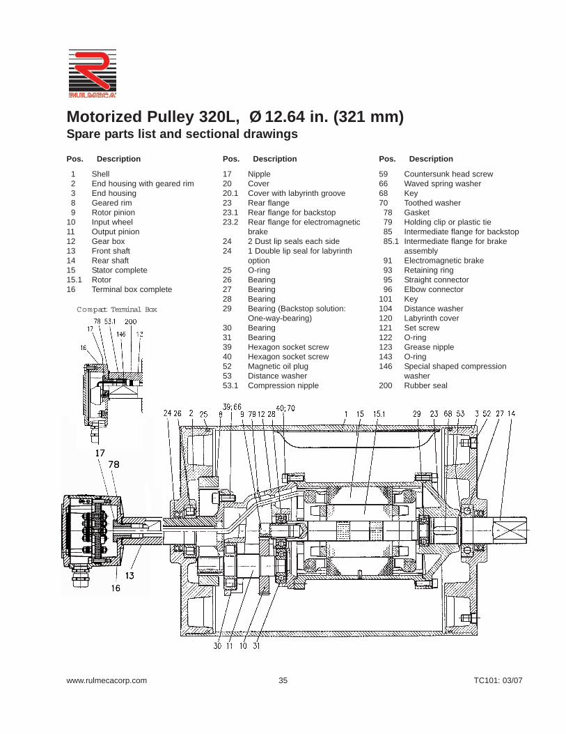
www.rulmecacorp.com TC101: 03/0735
1 Shell2 End housing with geared rim3 End housing8 Geared rim9 Rotor pinion
10 Input wheel11 Output pinion12 Gear box13 Front shaft14 Rear shaft15 Stator complete15.1 Rotor16 Terminal box complete
17 Nipple20 Cover20.1 Cover with labyrinth groove23 Rear flange23.1 Rear flange for backstop23.2 Rear flange for electromagnetic
brake24 2 Dust lip seals each side24 1 Double lip seal for labyrinth
option25 O-ring26 Bearing27 Bearing28 Bearing29 Bearing (Backstop solution:
One-way-bearing)30 Bearing31 Bearing39 Hexagon socket screw40 Hexagon socket screw52 Magnetic oil plug53 Distance washer53.1 Compression nipple
59 Countersunk head screw66 Waved spring washer68 Key70 Toothed washer
78 Gasket79 Holding clip or plastic tie85 Intermediate flange for backstop85.1 Intermediate flange for brake
assembly91 Electromagnetic brake93 Retaining ring95 Straight connector96 Elbow connector
101 Key104 Distance washer120 Labyrinth cover121 Set screw122 O-ring123 Grease nipple143 O-ring146 Special shaped compression
washer200 Rubber seal
Motorized Pulley 320L, Ø 12.64 in. (321 mm)Spare parts list and sectional drawings
Pos. Description Pos. Description Pos. Description
Compact Terminal Box

www.rulmecacorp.com TC101: 03/0736
29 Bearing30 Bearing31 Bearing32 Retaining ring33 Retaining ring 35 Retaining ring37 Hexagon socket screw43 Hexagon socket screw44 Hexagon socket screw45 Hexagon head screw46 Hexagon head screw49 Washer52 Magnetic oil plug53 Distance washer53.1 Compression nipple60 Parallel pin64 Prevailing torque type hexagon
nut66 Waved spring washer67 Waved spring washer68 Key70 Waved spring washer75 Gasket
1 Shell2 End housing with geared rim3 End housing8 Geared rim9 Rotor pinion
10 Input wheel11 Output pinion12 Gear box13 Front shaft14 Rear shaft15 Stator complete15.1 Rotor16 Terminal box complete17 Nipple20 Cover20.1 Cover with labyrinth groove23 Rear flange23.1 Rear flange for backstop/Brake24 2 Dust lip seals each side25 O-ring26 Bearing27 Bearing28 Bearing
78 Gasket79 Holding clip or plastic tie85 Intermediate flange for back-
stop85.1 Intermediate flange for brake
assembly91 Electromagnetic brake93 Retaining ring94 Hexagon head screw95 Straight connector 96 Elbow connector99 Waved spring washer
101 Key104 Distance washer120 Labyrinth cover121 Set screw122 O-ring123 Grease nipple143 O-ring146 Special shaped compression
washer200 Rubber seal
Motorized Pulley 320M, Ø 12.64 in. (321 mm)Spare parts list and sectional drawings
Pos. Description Pos. Description Pos. Description

www.rulmecacorp.com TC101: 03/0737
70 Waved spring washer73 Set screw75 Gasket78 Gasket79 Holding clip or plastic tie80 Hexagon head screw84 Rear flange for brake85 Intermediate flange for backstop85.1 Intermediate flange for brake
assembly90 Backstop91 Electromagnetic brake93 Retaining ring94 Hexagon head screw95 Straight connector96 Elbow connector99 Waved spring washer
101 Key104 Distance washer120 Labyrinth cover121 Set screw122 O-ring123 Grease nipple
1 Shell2 End housing with geared rim3 End housing8 Geared rim9 Rotor pinion
10 Input wheel11 Output pinion12 Gear box 13 Front shaft14 Rear shaft15 Stator complete15.1 Rotor16 Terminal box complete17 Nipple20 Cover front side20.1 Cover with labyrinth groove21 Cover – rear side21.1 Cover with labyrinth groove23 Rear flange23.1 Rear flange for brake option24 2 Dust lip seals each side25 O-ring26 Bearing27 Bearing28 Bearing29 Bearing20 Cover front side20.1 Cover with labyrinth groove21 Cover – rear side21.1 Cover with labyrinth groove23 Rear flange23.1 Rear flange for brake option24 2 Dust lip seals each side25 O-ring26 Bearing 27 Bearing28 Bearing29 Bearing30 Bearing31 Bearing32 Retaining ring 33 Retaining ring35 Retaining ring37 Hexagon socket screw43 Hexagon head screw44 Hexagon head screw45 Hexagon head screw46 Hexagon head screw49 Washer52 Magnetic oil plug53 Distance washer53.1 Compression nipple60 Parallel pin64 Hexagon head nut66 Waved spring washer67 Waved spring washer68 Key
143 O-ring146 Special shaped compression
washer180 Intermediate pinion shaft181 Intermediate pinion182 Distance bushing183 Washer184 Roller bearing185 Roller bearing186 Key187 Key188 Retaining ring190 Retaining ring191 Retaining ring192 Retaining ring193 Distance washer194 Set screw195 Prevailing torque type hexagon
nut196 Key197 Retaining ring198 Distance ring200 Rubber seal
Motorized Pulley 320H, Ø 12.64 in. (321 mm)Spare parts list and sectional drawings
Pos. Description Pos. Description Pos. Description
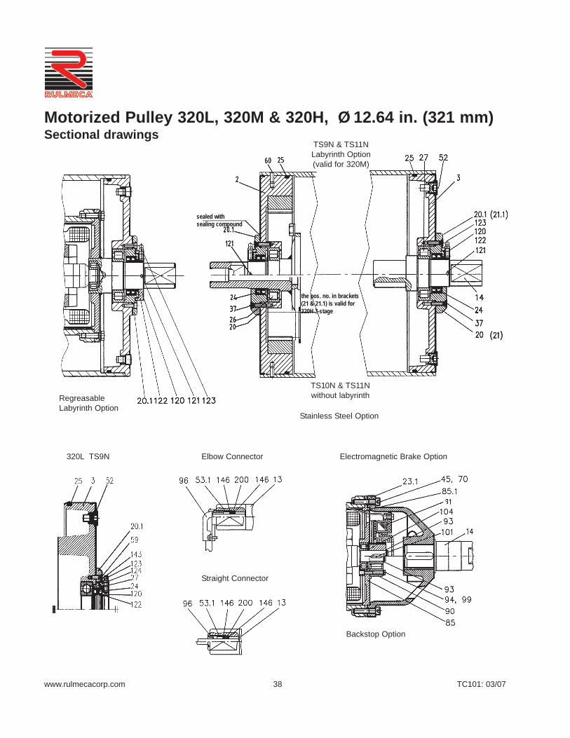
www.rulmecacorp.com TC101: 03/0738
320L TS9N Elbow Connector
Straight Connector
Stainless Steel Option
Electromagnetic Brake Option
Backstop Option
RegreasableLabyrinth Option
TS9N & TS11NLabyrinth Option(valid for 320M)
TS10N & TS11Nwithout labyrinth
Motorized Pulley 320L, 320M & 320H, Ø 12.64 in. (321 mm)Sectional drawings
sealed withsealing compound
the pos. no. in brackets(21 & 21.1) is valid for320H 3-stage

www.rulmecacorp.com TC101: 03/0739
Taconite Ship Loading Terminal (Michigan—USA)DEMAG crawler-mounted bucket wheel reclaimer handles taconite pellets at5,000 TPH on 72” wide boom and tail belts at this Escanaba, Michigan facil-ity. Terminal operator replaced both original Kufnagel conveyor drives with40” diameter Rulmeca Motorized Pulleys in 1985 after 13 years of service.Photo shows tail-mounted 200 HP drive pulley for discharge conveyor.
Marl Pit at Cement Plant (South Carolina—USA)FAM delivered this crawler-mounted bucket wheel reclaimer in 2002 toexcavate marl from a pit adjacent to the producer’s cement plant nearCharleston, South Carolina. It uses tail-mounted 31.5” diameter 100 HPMotorized Pulleys to drive the 54” wide boom and tail conveyor belts at 600fpm. Externally mounted brakes prevent material from “rolling backwards”when conveyors are stopped because both conveyors can articulate to a 16ºmaximum inclination.
Granite Quarry (Connecticut—USA)Built in 2003 by RR Equipment, this mobile recirculating crushing andscreening rig uses a tail-mounted 15 HP 15.75” diameter Motorized Pulleyto drive the 36” wide 300 TPH 58’ long screen feed conveyor. Note that useof slender “Telescoping” mechanical belt take-up allows compact and light-weight structure. This plant adheres to the maximum US highway clearancerequirements of 12’-0” wide by 13’-6” high.
Technical Precaution: When mounting a motorized pulley in a screw take-up always make sure that pulley centerline is perpendicular to belt center-line to avoid overstressing internal bearings.
Trap Rock Quarry (New York—USA)Allis Mineral Systems delivered this 850 TPH recirculating crushing andscreening plant in 1994. The tail-mounted 15.75” diameter 15 HP MotorizedPulley drives the 36” wide screen feed belt, in tandem with an identicalhead-mounted drive, at 384 fpm. Motorized Pulleys enabled designers toadhere to the 12’ maximum allowable US highway clearance width. Taildrive is mounted in a “Sliding Pedestal” mechanical belt take-up.
Technical Precaution: When mounting a motorized pulley in a screw take-up always make sure that pulley centerline is perpendicular to belt center-line to avoid overstressing internal bearings.
Motorized PulleysTail Drives

STANDARD SPECIFICATIONof Motorized Pulley
• Crowned mild steel 15.91” diameter steelshell painted yellow at a minimum thick-ness of 2.4 mils
• Bolted powder coated cast iron bearinghousings and covers, all painted yellowat a minimum thickness of 2.4 mils
• Mild steel shafts treated w/anti-rust wax• Shaft sealing system - degree of protec-
tion IP66/67 (EN60034-5.) See pg 88.• Powder coated aluminum terminal box
for 400L• Cast iron terminal box for 400M & 400H
painted yellow at min.thickness of 2.4mils
• 3-phase induction motors with thermalprotector
• Voltage: All common voltages available.Please specify.
• Motor winding insulation Class F• Dynamically balanced rotor• Two oil plugs each fitted with a magnet
to filter the oil• Oil change recommended every 10,000
operational hours• Minimum RL. Refer to pages 43-44 • Maximum RL - Please inquire• Non standard RL’s available• To be used in horizontal positions ±5
degree only
Please note:
• Noise-sensitive Areas: High speed 2-pole motors can cause higher noise lev-els and are not recommended for noise-sensitive areas
• Technical Precautions for Design,Installation, and Maintenance: pages76-86
• Environmental Considerations: pg 72• Optional Extras: pg 41 and back cover• Electrical Connection Diagrams:
pages 94-96.
STAINLESS STEEL options
TS9N • Stainless steel shell - AISI 304 range• Stainless steel shafts - AISI 303/4 range• Stainless steel covered bearing hous-
ings - AISI 316 range• Regreasable bearing covers with
labyrinth grooves and labyrinth sealswith grease nipples in stainless steel- AISI 304 range
www.rulmecacorp.com TC101: 03/0740
Motorized Pulley 400L, 400M & 400H, Ø 15.91 in. (404 mm)Our 15.91” diameter Motorized Pulleyrange offers three differentperformance levels for BULKapplications:
- L for Light duty- M for Medium duty- H for Heavy duty
It is important to note the productdifferences and choose theappropriate pulley based onestimated belt tension (radial load.)See page 78. The actual radial loadmust be less than the maximumallowable radial load shown in thiscatalog.
Be aware of increased belt tensions required to drive multi-plythick heavy belts and/or larger beltwidths.
If the 15.91” diameter model is notstrong enough to resist estimatedbelt tension, then select 19.72”diameter model.
L for Light duty400L is designed for regular andcontinuous operating conditions. Itis advisable to rubber lag thesepulleys to grip the belt and limit belttension. A popular application is self-cleaning magnetic separators. 400Luses motor and gearbox from 320M.
M for Medium duty400M is designed for tough andirregular operating conditions. 400Mis typically used in heavy mobilecrushing & screening applications aswell as in crushed stone, ore,cement, steel, and fertilizer handling.
H for Heavy dutyA solid 3-stage gearbox enables the400H to provide low speed at hightorque and handle irregular loadingsin harsh operating conditions.
• Stainless steel oil plugs - AISI 304range – one out of two with magnet
• Stainless steel exterior bolts - AISI 304range
• Shaft sealing system – degree of pro-tection IP66/67 (EN60034-5) See pg 88
TS10N • As TS9, but without regreasable
labyrinth seals
SEMI-RUST-FREE options
TS 11N• Painted mild steel shell – min. thickness
of 4.7 mils• Stainless steel shafts - AISI 303/4 range• Stainless steel covered cast iron bear-
ing housing - AISI 316 range• Regreasable bearing covers with
labyrinth grooves and grease nipples instainless steel - AISI 304 range
• Stainless steel oil plugs – AISI 304range - one out of two with magnet
• Stainless steel exterior bolts - AISI 304range
• Shaft sealing system - degree of pro-tection IP66/67 (EN60034-5)
• Powder coated terminal box for 400L• Painted terminal box - min. thickness of
4.7 mils for 400M & 400H
TS12N• As TS11N, but without regreasable
seals.• Covers - standard
Other Stainless Options:
• FDA & USDA food grade recognized oiland grease are not included in TS9N -TS12N, but available on request
• Complete Motorized Pulleys in acidresistant stainless steel - AISI 316range - available on request.
• Special mounting brackets available
Electrical connection options:
• Salt water resistant powder coated alu-minum terminal box with zinc platedexterior bolts
• Stainless steel terminal box - AISI 304range (400L < 5.5 HP only)
• Straight stainless steel connector withflying lead - AISI 304 range < 5.5 HPonly.
Please specify required TS-numberwhen ordering Stainless Steeloptions..

www.rulmecacorp.com TC101: 03/0741
OPTIONAL EXTRASMotorized Pulley 400L, 400M & 400H
x = Optional extraso = An option with certain limitations. Please refer to Technical precautions pages 76-86.Std. = Fitted as standard
Total stainless steel option AISI 304 range TS9N with regreasable labyrinth seals xTotal stainless steel option AISI 304 range TS10N with standard seals xSemi-rust free option TS11N with regreasable labyrinth seals xSemi-rust free option TS12N with standard seals xRegreasable labyrinth seals xFood grade oil & grease - FDA & USDA recognized xDust explosion proof Motorized Pulleys - ATEX 95 - Zone 22 - for applications handling of dusty grain etc.According to European Directive 94/9/EC. xTotal acid resistant stainless steel option - AISI 316 range xBlack rubber lagging - Standard specifications (See page 80.)
5/16” full diamond lagging - Hardness 60 ±5 Shore A < 15 HP o5/16” partial diamond lagging - Hardness 60 ±5 Shore A 20 HP o
White smooth rubber lagging (FDA listed) - Oil, fat & grease resistant oSpecial lagging (e.g. hot vulcanized) oElectromagnetic brake Min RL increases by 3.94” xMechanical backstop Min. RL increases by 1.97” for 400L x
Min. RL = 29.53” for 400M xMin. RL = 31.50” for 400H x
Modified for vertical mounting oModified for mounting between 5° and 90° oInsulation class F with standard oil: (Allowable ambient temperature -13°F/+104°F) Std.Insulation class H with synthetic oil: (Allowable ambient temperature -13°F/+120°F) xSpecial motors for applications with no belt contact oLow noise drives for noise sensitive areas xParallel shell (i.e. no crown) xThermal protector Std.IP66/67 Standard yellow powder coated aluminum terminal box 400L Std.IP66/67 Optional gray powder coated aluminum terminal box (food grade approved) 400L xIP66/67 Standard yellow powder coated cast iron terminal box 400M & 400H Std.Straight or elbow connector with standard power cord < 5.5 HP only xStraight connector with screened power cord (See page 86 for VFD precautions) < 5.5 HP only xStraight connector with power cord (Stainless steel in AISI 304 range) < 5.5 HP only xVoltage: < 5.5 HP dual voltage (230/460) stator (YY/Y winding) wired for 460v/3ph/60 Hz at terminal box Std.
< 5.5 HP dual voltage (230/460) stator (YY/Y winding) wired for 230v/3ph/60 Hz at terminal box x> 7.5 HP single voltage (460) stator (Y winding) wired for 460v/3ph/60 Hz at terminal box Std> 7.5 HP single voltage (230) stator (YY winding) wired for 230v/3ph/60 Hz at terminal box x
2 speed motors xSpecial voltage motors xCSA approved motors x
Specification Availability
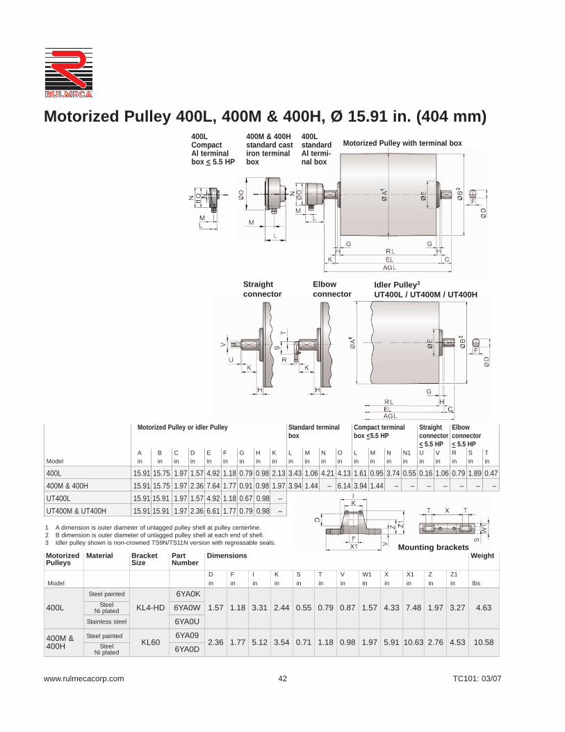
www.rulmecacorp.com TC101: 03/0742
Motorized Pulley with terminal box400LstandardAl termi-nal box
400M & 400Hstandard castiron terminalbox
400LCompact Al terminalbox < 5.5 HP
Straight connector
Elbow connector
Idler Pulley3
UT400L / UT400M / UT400H
Motorized Pulley or idler Pulley Standard terminal Compact terminal Straight Elbowbox box <5.5 HP connector connector
< 5.5 HP < 5.5 HPA B C D E F G H K L M N O L M N N1 U V R S T
Model in in in in in in in in in in in in in in in in in in in in in in
400L 15.91 15.75 1.97 1.57 4.92 1.18 0.79 0.98 2.13 3.43 1.06 4.21 4.13 1.61 0.95 3.74 0.55 0.16 1.06 0.79 1.89 0.47400M & 400H 15.91 15.75 1.97 2.36 7.64 1.77 0.91 0.98 1.97 3.94 1.44 – 6.14 3.94 1.44 – – – – – – –UT400L 15.91 15.91 1.97 1.57 4.92 1.18 0.67 0.98 –UT400M & UT400H 15.91 15.91 1.97 2.36 6.61 1.77 0.79 0.98 –
Motorized Pulley 400L, 400M & 400H, Ø 15.91 in. (404 mm)
ModelDin
Fin
Iin
Kin
Sin
Tin
Vin
W1in
Xin
X1in
Zin
Z1in lbs
400L
Steel painted
KL4-HD
6YA0K
1.57 1.18 3.31 2.44 0.55 0.79 0.87 1.57 4.33 7.48 1.97 3.27 4.63Steel Ni plated 6YA0W
Stainless steel 6YA0U
400M &400H
Steel paintedKL60
6YA092.36 1.77 5.12 3.54 0.71 1.18 0.98 1.97 5.91 10.63 2.76 4.53 10.58Steel
Ni plated 6YA0D
Mounting bracketsMotorizedPulleys
Material BracketSize
PartNumber
Dimensions Weight
1 A dimension is outer diameter of unlagged pulley shell at pulley centerline.2 B dimension is outer diameter of unlagged pulley shell at each end of shell.3 Idler pulley shown is non-crowned TS9N/TS11N version with regreasable seals.

www.rulmecacorp.com TC101: 03/0743
Motorized Pulley 400L, Ø 15.91 in. (404 mm) 60 HzMotor
No.Gear
StagesModel
Nominal beltspeed1 atFull Load
60 Hzfpm
Actual beltspeed1 atFull Load
60 Hzfpm
BeltPull2
lbs
Max.RadialLoad3
T1 + T2lbs
Min.RL
in
RL Dimension inches (RL>78.74” available on request)Weight in lbs5 Type
ofBracket
Power
HP
No.of
Poles 19.69 21.65 23.62 25.59 27.56 29.53 31.50 33.46 35.43 37.40longerthan
37.40
3 4 2 400L
192240300384480600
201240303395498613
460385305234186151
4496 19.69 276* 288 300 312 324 337 349 361 373 385
SeeFoot-note4
KL41-HD6YA0K
4 4 2 400L
150192240300384480600
163201240303395498613
771627524416319253206
4496 19.69 276* 288 300 312 324 337 349 361 373 385
5.5 4 2 400L
192240300384480600
201240303395498613
836700554425338274
4496 19.69 298* 310 322 334 346 359 371 383 395 407
7.5 4 2 400L300384480600
303395498613
778598474386
4496 19.69 298* 310 322 334 346 359 371 383 395 407
10 2 2 400L384480600768
402481607791
784655520399
4496 19.69 298* 310 322 334 346 359 371 383 395 407
Idler Pulley Model UT400L 4496 19.69 188 200 212 224 236 249 261 273 285 297SeeFoot-note4
KL41-HD6YA0K
1 Use “nominal belt speed” to specify pulley. “Actual belt speed” is presented (for pulley lagged with 5/16” thick rubber) to assist with process design calculations.See Technical Precautions page 77. Note that “actual belt speed” decreases when lagging is not used due to decreased pulley diameter.
2 Belt pull value allows for gearbox loss.3 Pulley must not be subjected to radial load exceeding “Maximum radial load” defined above. See “Belt Tension” section in Technical Precautions, page 78.4 Additional Motorized Pulley and Idler Pulley weight, specified per Roller Length: 37.40”< RL < 78.74” Wt = 6.2 lbs/in.5 All weights shown above are for pulleys with 5/16” thick lagging. To calculate unlagged pulley weight subtract 0.6 lbs/in of Roller Length from above.
* Special “Short Roller Length” Option
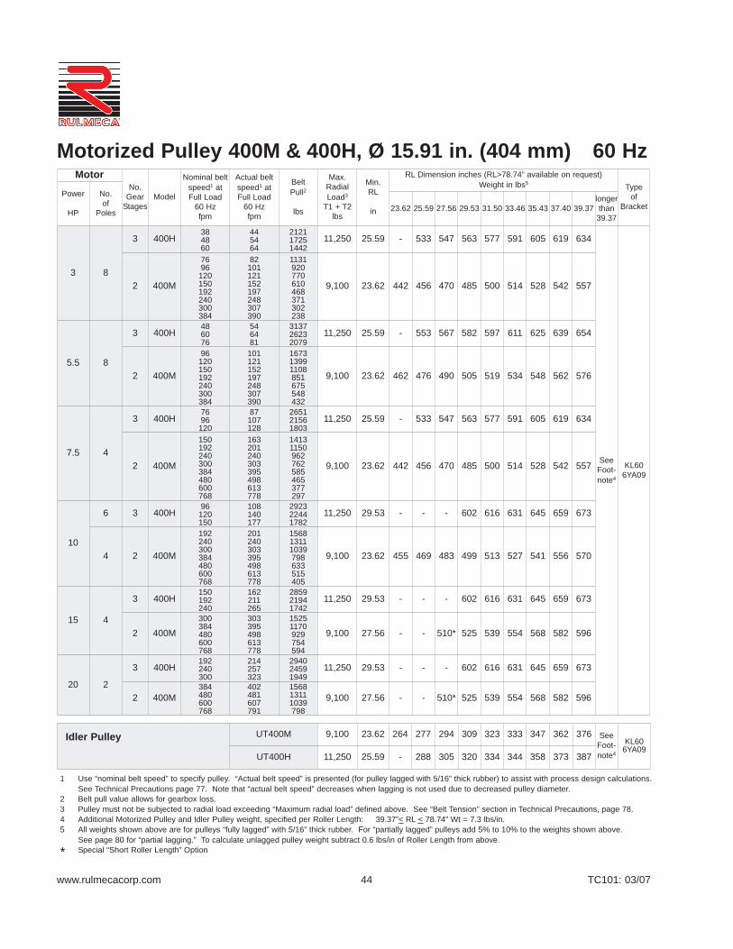
www.rulmecacorp.com TC101: 03/07
Motorized Pulley 400M & 400H, Ø 15.91 in. (404 mm) 60 HzMotor
No.Gear
StagesModel
Nominal beltspeed1 atFull Load
60 Hzfpm
Actual beltspeed1 atFull Load
60 Hzfpm
BeltPull2
lbs
Max.RadialLoad3
T1 + T2lbs
Min.RL
in
RL Dimension inches (RL>78.74” available on request)Weight in lbs5 Type
ofBracket
Power
HP
No.of
Poles 23.62 25.59 27.56 29.53 31.50 33.46 35.43 37.40 39.37longerthan
39.37
3 8
3 400H384860
445464
212117251442
11,250 25.59 - 533 547 563 577 591 605 619 634
SeeFoot-note4
KL606YA09
2 400M
7696
120150192240300384
82101121152197248307390
1131920770610468371302238
9,100 23.62 442 456 470 485 500 514 528 542 557
5.5 8
3 400H486076
546481
313726232079
11,250 25.59 - 553 567 582 597 611 625 639 654
2 400M
96120150192240300384
101121152197248307390
167313991108851675548432
9,100 23.62 462 476 490 505 519 534 548 562 576
7.5 4
3 400H7696
120
87107128
265121561803
11,250 25.59 - 533 547 563 577 591 605 619 634
2 400M
150192240300384480600768
163201240303395498613778
14131150962762585465377297
9,100 23.62 442 456 470 485 500 514 528 542 557
10
6 3 400H96
120150
108140177
292322441782
11,250 29.53 - - - 602 616 631 645 659 673
4 2 400M
192240300384480600768
201240303395498613778
156813111039798633515405
9,100 23.62 455 469 483 499 513 527 541 556 570
15 4
3 400H150192240
162211265
285921941742
11,250 29.53 - - - 602 616 631 645 659 673
2 400M300384480600768
303395498613778
15251170929754594
9,100 27.56 - - 510* 525 539 554 568 582 596
20 2
3 400H192240300
214257323
294024591949
11,250 29.53 - - - 602 616 631 645 659 673
2 400M384480600768
402481607791
156813111039798
9,100 27.56 - - 510* 525 539 554 568 582 596
Idler Pulley UT400M 9,100 23.62 264 277 294 309 323 333 347 362 376 SeeFoot-note4
KL606YA09
UT400H 11,250 25.59 - 288 305 320 334 344 358 373 387
1 Use “nominal belt speed” to specify pulley. “Actual belt speed” is presented (for pulley lagged with 5/16” thick rubber) to assist with process design calculations.See Technical Precautions page 77. Note that “actual belt speed” decreases when lagging is not used due to decreased pulley diameter.
2 Belt pull value allows for gearbox loss.3 Pulley must not be subjected to radial load exceeding “Maximum radial load” defined above. See “Belt Tension” section in Technical Precautions, page 78.4 Additional Motorized Pulley and Idler Pulley weight, specified per Roller Length: 39.37”< RL < 78.74” Wt = 7.3 lbs/in.5 All weights shown above are for pulleys “fully lagged” with 5/16” thick rubber. For “partially lagged” pulleys add 5% to 10% to the weights shown above.
See page 80 for “partial lagging.” To calculate unlagged pulley weight subtract 0.6 lbs/in of Roller Length from above.
* Special “Short Roller Length” Option
44
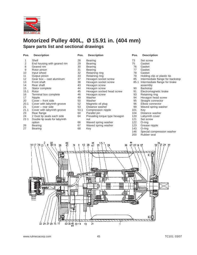
www.rulmecacorp.com TC101: 03/0745
28 Bearing29 Bearing 30 Bearing31 Bearing32 Retaining ring 33 Retaining ring37 Hexagon socket screw38 Hexagon socket screw43 Hexagon screw44 Hexagon screw45 Hexagon socked head screw46 Hexagon screw49 Washer50 Washer52 Magnetic oil plug53 Distance washer53.1 Compression nipple60 Parallel pin64 Prevailing torque type hexagon
nut66 Waved spring washer67 Waved spring washer68 Key
1 Shell2 End housing with geared rim8 Geared rim9 Rotor pinion
10 Input wheel11 Output pinion12 Gear box – cast aluminum13 Front shaft14 Rear shaft15 Stator complete15.1 Rotor16 Terminal box complete17 Nipple20 Cover – front side20.1 Cover with labyrinth groove21 Cover – rear side21.1 Cover with labyrinth groove23 Rear flange24 2 Dust lip seals each side23 1 Double lip seals for labyrinth
option26 Bearing27 Bearing
73 Set screw75 Gasket
76 Gasket77 Gasket78 Gasket79 Holding clip or plastic tie85 Intermediate flange for backstop85.1 Intermediate flange for brake
assembly90 Backstop91 Electromagnetic brake93 Retaining ring94 Hexagon head screw95 Straight connector96 Elbow connector99 Waved spring washer
101 Key104 Distance washer120 Labyrinth cover121 Set screw122 O-ring123 Grease nipple143 O-ring146 Special compression washer200 Rubber seal
Motorized Pulley 400L, Ø 15.91 in. (404 mm)Spare parts list and sectional drawings
Pos. Description Pos. Description Pos. Description

www.rulmecacorp.com TC101: 03/0746
24 2 Dust lip seals each side26 Bearing27 Bearing28 Bearing29 Bearing30 Bearing31 Bearing32 Retaining ring36 Hexagon head screw45 Hexagon screw
50 Waved spring washer52 magnetic oil plug37 Hexagon socket screw38 Hexagon socket screw43 Hexagon screw44 Hexagon screw52 Magnetic oil plug53 Distance washer66 Waved spring washer
1 Shell2 End housing with geared rim3 End housing8 Geared rim9 Rotor pinion
10 Input wheel11 Output pinion12 Gear box – cast aluminum13 Front shaft14 Rear shaft15 Stator complete15.1 Rotor16 Terminal box complete17 Nipple20 Cover – front side20.1 Cover with labyrinth groove21 Cover – rear side21.1 Cover with labyrinth groove23 Rear flange
67 Waved spring washer70 Spring washer73 Set screw75 Gasket76 Gasket77 Gasket78 Gasket85 Intermediate flange 90 Backstop91 Electromagnetic brake93 Retaining ring94 Hexagon head screw99 Waved spring washer
101 Key104 Distance washer120 Labyrinth cover121 Set screw122 O-ring123 Grease nipple
Motorized Pulley 400M, Ø 15.91 in. (404 mm)Spare parts list and sectional drawings
Pos. Description Pos. Description Pos. Description

www.rulmecacorp.com TC101: 03/0747
31 Bearing32 Retaining ring33 Retaining ring36 Hexagon socket screw37 Hexagon socket screw38 Hexagon socket screw43 Hexagon socket screw44 Hexagon socket screw45 Hexagon socket screw50 Waved spring washer52 Magnetic oil plug53 Distance washer66 Waved spring washer72 Taper grooved pin73 Set screw75 Gasket76 Gasket77 Gasket78 Gasket85 Intermediate flange for brake
assembly90 Backstop91 Electromagnetic brake
1 Shell2 End housing with geared rim8 Geared rim9 Rotor pinion
10 Input wheel11 Output pinion12 Gear box – cast iron13 Rear shaft14 Front shaft15 Stator complete15.1 Rotor16 Terminal box complete17 Nipple20 Cover rear side20.1 Cover with labyrinth groove21 Cover front side21.1 Cover with labyrinth groove23 Rear flange24 2 Dust lip seals26 Bearing27 Bearing28 Bearing30 Bearing
93 Retaining ring94 Hexagon head screw99 Waved spring washer
101 Key104 Distance washer120 Labyrinth cover121 Fixing bolt122 O-ring123 Grease nipple180 Intermediate pinion shaft181 Intermediate wheel182 Distance washer183 Distance washer184 Roller bearing185 Roller bearing186 Key187 Key188 Retaining ring190 Retaining ring191 Retaining ring194 Set screw196 Key197 Retaining ring
Motorized Pulley 400H, Ø 15.91 in. (404 mm)Spare parts list and sectional drawings
Pos. Description Pos. Description Pos. Description

www.rulmecacorp.com TC101: 03/0748
Motorized Pulley 400L, 400M & 400H, Ø 15.91 in. (404 mm)Sectional drawings
400L: TS9N & TS11NLabyrinth Option
400M - 400H: TS9N & TS11NLabyrinth Option
400M - 400H: TS10N & TS12NStainless Steel Option without Labyrinth
400M - 400H Backstop Option 400M - 400H Electromagnetic Brake Option
400L Electromagnetic Brake Option
400L Backstop Option

www.rulmecacorp.com TC101: 03/0749
Limestone Quarry (Georgia—USA)Two 15.75” diameter 5.5 HP Motorized Pulleys were installed 1994 to auto-matically “choke feed” tertiary gyratory crushers, working in combinationwith variable frequency drives (VFD) and ultrasonic sensors. Each pulleydrives a 36” wide belt at a maximum speed of 120 FPM to transfer 4” minusproduct at 425 TPH.
Technical Precaution: When driving motorized pulley with VFD on 460 volt3 phase 60 Hz power supply, always restrict frequencies to allowable fre-quency spectrum of 12 to 66 Hz to avoid torque loss and heat build-up. Fil-ter VFD output if VFD is more than 30’ from motorized pulley to avoid reso-nance-induced voltage spikes.
Taconite Processing Plant (Minnesota—USA)Two limestone feeder belt drives beneath storage silo were converted from20-year-old DC motors to AC-powered motorized pulleys in 1995. An ABBVFD drives each 19.72” diameter 5.5 HP motorized pulley to a maximum of120 FPM. Conversion enabled plant operator to eliminate exposed motorsand gearboxes and replace SCRs, relays, and timer banks with VFDs incontrol panel.
Technical Precaution: When driving motorized pulley with VFD on 460 volt3 phase 60 Hz power supply, always restrict frequencies to allowable fre-quency spectrum of 12 to 66 Hz to avoid torque loss and heat build-up. Fil-ter VFD output if VFD is more than 30’ from motorized pulley to avoid reso-nance-induced voltage spikes.
Electric Power Plant (Connecticut—USA)Designed and built in 1989 by ABB, this refuse derived fuel (RDF) plant usestwo 12’ diameter trommels to separate light burnable trash from landfillmaterial. A 24.80” diameter 30 HP Motorized Pulley drives each steeplyinclined trommel feed conveyor at 300 FPM. Each 100’ long 48” wide feedbelt is fitted with cleats and sidewalls to elevate 250 TPH of refuse at 45ºinclination.
Technical Precaution: When using motorized pulley to drive a single direc-tion belt on an incline use built-in mechanical backstop to prevent materialfrom rolling downhill when belt stops.
Foundry for Railroad Truck Castings (Ohio—USA)Installed at first American Steel Foundries (now Alliance Castings Company)plant in 1980, this 15.75” diameter 10 HP motorized pulley transfers recy-cled foundry sand to mold area at 150 TPH. Conveyor makes 30 start/stopsper hour. Ambient environment is hot (>104º F) and contains a high per-centage of airborne abrasive particulate. Photo taken in 1993, after 13years of service.
Technical Precaution: When installing motorized pulley in hot environment(>104º F), specify optional Class H motor windings and synthetic oil. Con-tact Rulmeca if ambient temperature will exceed 120º F.
Motorized PulleysHopper Feeder Drives

www.rulmecacorp.com TC101: 03/0750
Motorized Pulley 500L, 500M & 500H, Ø 19.72 in. (501 mm)Our 19.72” diameter Motorized Pulleyrange offers three differentperformance levels for BULKapplications:
- L for Light duty- M for Medium duty- H for Heavy duty
It is important to notice the productdifferences and choose theappropriate pulley based onestimated belt tension (radial load.)See page 78. The actual radial loadmust be less than the maximumallowable radial load shown in thiscatalog.
Be aware of increased belt tensions required to drive multi-plythick heavy belts and/or larger beltwidths.
If the 19.72” diameter model is notstrong enough to resist estimatedbelt tension, then select 24.80”diameter model.
L for Light duty500L is designed for tough andirregular operating conditions. 500Lis typically used in heavy mobilecrushing & screening applications aswell as in crushed stone, ore, cement,steel, and fertilizer handling. 500Luses motor and gearbox from 400M.Note that 500L outer dimensions donot match 500H (Former modelsTM500 and TM501).
M for Medium dutyA solid 3-stage gearbox enables the500M to provide low speed at hightorque and handle irregular loadingsin harsh operating conditions. 500Muses motor and gearbox from 400H.Note that 500M outer dimensions donot match 500H (Former modelsTM500 and TM501).H for Heavy duty500H has strongest internalcomponents in this diameter withgearbox, shaft, and bearingsdesigned for tough, irregular, andextreme operating conditions.
STANDARD SPECIFICATIONof Motorized Pulley
• Crowned mild steel 19.72” diametersteel shell painted yellow at a minimumthickness of 2.4 mils
• Bolted powder coated cast iron bearinghousings and covers, all painted yellowat a minimum thickness of 2.4 mils
• Mild steel shafts• Shaft sealing system - degree of pro-
tection IP66/67 (EN60034-5.) Seepage 88.
• Cast iron terminal box for painted yel-low at min.thickness of 2.4 mils
• 3-phase induction motors with thermalprotector
• Voltage: All common voltages avail-able. Please specify.
• Motor winding insulation Class F• Dynamically balanced rotor• Two oil plugs each fitted with a magnet
to filter the oil• Black painted mounting brackets
(KL60) for 500L and 500M available onrequest
• Yellow painted mounting brackets(AL65 & ALO65) included with 500H
• Oil change recommended every10,000 operational hours
• Minimum RL. Refer to pages 53 & 58• Maximum RL - Please inquire• Non standard RL’s available• To be used in horizontal positions ±5
degree only
Please note:
• Noise-sensitive Areas: High speed 2-pole motors can cause higher noiselevels and are not recommended fornoise-sensitive areas
• Technical Precautions for Design,Installation, and Maintenance:pages 76-86
• Environmental Considerations:page 72
• Optional Extras: page 51 and backcover
• Electrical Connection Diagrams:pages 94-96.
SEMI-RUST-FREE options
TS11 – (500L & 500M)• Painted mild steel shell at minimum
thickness of 4.7 mils• Stainless steel shafts – AISI 303/4
range• Painted cast iron end housings at mini-
mum thickness of 4.7 mils• Stainless steel bearing covers with
labyrinth grooves and grease nipples –AISI 304 range
• Zinc plated oil plugs each with magnet• Zinc plated exterior bolts • Shaft sealing system – degree of pro-
tection IP66/67 (EN60034-5.) Seepage 88.
• Painted terminal box at minimum thick-ness of 4.7 mils
• Nickel plated mounting brackets areavailable
TS11 – (500H)• Painted mild steel shell at minimum
thickness of 4.7 mils• Painted cast iron end housings at mini-
mum thickness of 4.7 mils• Stainless steel covers with labyrinth
grooves – AISI 304 range• Nitrided shaft sleeves• Zinc-plated oil plugs - each with mag-
net• Zinc-plated exterior bolts • Shaft sealing system – degree of pro-
tection P66/67 (EN60034-5) See pg 88.• Painted terminal box at minimum thick-
ness of 4.7 mils• Nickel plated mounting brackets with
labyrinth grooves
TS12• As TS11, but without regreasable
seals.• Covers - standard
Please note:
• FDA & USDA food grade recognized oiland grease are not included in TS11 &TS12, but available on request
Please specify required TS-numberwhen ordering Stainless Steeloptions.

www.rulmecacorp.com TC101: 03/0751
OPTIONAL EXTRASMotorized Pulley 500L, 500M & 500H
Semi-rust-free option TS11 with regreasable labyrinth seals xSemi-rust-free option TS12 with standard seals xRegreasable labyrinth seals xDust explosion proof Motorized Pulleys - ATEX 95 - Zone 22 - for applications handling of dusty grain etc. According to European Directive 94/9/EC. xStandard black rubber lagging (See page 80.)
3/8” full smooth lagging - Hardness 60 ±5 Shore A o3/8” full diamond lagging - Hardness 60 ±5 Shore A o3/8” partial smooth lagging - Hardness 60 ±5 Shore A o
White smooth rubber lagging (FDA listed) - Oil, fat & grease resistant oSpecial lagging - e.g. hot vulcanized, partial, and ceramic (See page 80.) oInternal electromagnetic brake (not available in 500H) Min. RL increases by 3.94” for 500L and 500M x External brake shaft (for mechanical brake by others) Only available in 500H xMechanical backstop Min. RL = 29.53” for 500L x
Min. RL = 31.50” for 500M x Min. RL = 29.53” for 500H x
Insulation class F with standard oil: (allowable ambient temperature: -13°F/+104°F) Std.Insulation class H with synthetic oil: (allowable ambient temperature: -13°F/+120°F) xParallel shell xThermal protector Std.Voltage: Single voltage (460) stator (Y winding) wired for 460v/3ph/60 Hz at terminal box Std.IP66/67 Standard yellow powder coated cast iron terminal box Std.Special voltage motors xCSA approved motors x
x = Optional extraso = An option with certain limitations. Please refer to Technical precautions pages 76-86.Std. = Fitted as standard
Specification Availability
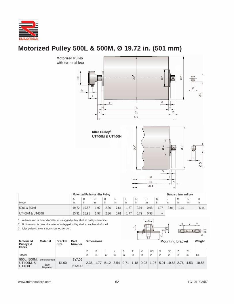
www.rulmecacorp.com TC101: 03/0752
Motorized Pulley with terminal box
Idler Pulley3
UT400M & UT400H
Motorized Pulley or Idler Pulley Standard terminal boxA B C D E F G H K L M N O
Model in in in in in in in in in in in in in
500L & 500M 19.72 19.57 1.97 2.36 7.64 1.77 0.91 0.98 1.97 3.94 1.44 – 6.14
UT400M & UT400H 15.91 15.91 1.97 2.36 6.61 1.77 0.79 0.98 –
Motorized Pulley 500L & 500M, Ø 19.72 in. (501 mm)
ModelDin
Fin
Iin
Kin
Sin
Tin
Vin
W1in
Xin
X1in
Zin
Z1in lbs
500L, 500M,UT400M, &UT400H
Steel paintedKL60
6YA092.36 1.77 5.12 3.54 0.71 1.18 0.98 1.97 5.91 10.63 2.76 4.53 10.58Steel
Ni plated 6YA0D
MotorizedPulleys &Idlers
Material BracketSize
PartNumber
Dimensions Weight
1 A dimension is outer diameter of unlagged pulley shell at pulley centerline.2 B dimension is outer diameter of unlagged pulley shell at each end of shell.3 Idler pulley shown is non-crowned version.
Mounting bracket

www.rulmecacorp.com TC101: 03/0753
Motorized Pulley 500L & 500M, Ø 19.72 in. (501 mm) 60 HzMotor
No.Gear
StagesModel
Nominal beltspeed1 atFull Load
60 Hzfpm
Actual beltspeed1 atFull Load
60 Hzfpm
BeltPull2
lbs
Max.RadialLoad3
T1 + T2lbs
Min.RL
in
RL Dimension inches (RL>78.74” available on request)Weight in lbs5 Type
ofBracket
Power
HP
No.of
Poles 23.62 25.59 27.56 29.53 31.50 33.46 35.43 37.40 39.37longerthan
39.37”
3 8
3 500M486076
556780
169613801154
9487 25.59 - 593 610 628 645 663 680 697 715
SeeFoot-note4
KL606YA09
2 500L96
120150192240
102126151190247
905736616487375
7868 23.62 498 516 533 550 568 585 603 620 638
5.5 8
3 500M7696
120
80101126
209816631338
9487 25.59 - 613 630 647 665 682 699 717 735
2 500L
150192240300384480
151190247311383487
1119887681540439346
7868 23.62 518 535 553 570 588 605 623 640 657
7.5 4
3 500M120150192
134160202
172514421144
9487 25.59 - 593 610 628 645 663 680 697 715
2 500L
240300384480600768
251301379494622766
920770610468372302
7868 23.62 498 516 533 550 568 585 603 620 638
10
6 3 500M150192240
175221272
179514251157
9487 29.53 - - - 641 658 676 693 711 728
4 2 500L300384480600768
301379494622766
1049831639507411
7868 23.62 511 529 546 564 581 599 616 633 651
15 43 500M
240300384
251301379
184015381220
9487 29.53 - - - 667 685 702 720 737 755
2 500L480600768
494622766
936743604
7868 27.56 - - 573* 590 608 625 642 660 677
20 23 500M
300384480
321405527
196715601196
9487 29.53 - - - 667 685 702 720 737 755
2 500L 600768
601759
1049831 7868 27.56 - - 573* 590 608 625 642 660 677
Idler Pulley UT400M 9,100 23.62 271 286 304 319 334 345 360 376 391 SeeFoot-note4
KL606YA09
UT400H 11,250 25.59 - 295 315 330 345 356 371 387 402
1 Use “nominal belt speed” to specify pulley. “Actual belt speed” is presented (for pulley lagged with 3/8” thick rubber) to assist with process design calculations.See Technical Precautions page 77. Note that “actual belt speed” decreases when lagging is not used due to decreased pulley diameter.
2 Belt pull value allows for gearbox loss.3 Pulley must not be subjected to radial load exceeding “Maximum radial load” defined above. See “Belt Tension” section in Technical Precautions, page 78.4 Additional Motorized Pulley weight, specified per Roller Length: 39.37”< RL < 78.749” Wt = 8.7 lbs/in. Pulley weight: 39.37”< RL < 78.74” Wt = 7.6 lbs/in.5 All weights shown above are for pulleys “fully lagged” with 3/8” thick rubber. To calculate unlagged pulley weight subtract 0.9 lbs/in of Roller Length from above.*
Special “Short Roller Length” Option

www.rulmecacorp.com TC101: 03/0754
31 Bearing32 Retaining ring 36 Hexagon socket screw37 Hexagon socket screw38 Hexagon socket screw43 Hexagon screw44 Hexagon screw45 Hexagon screw50 Waved spring washer51 Gasket52 Magnetic oil plug53 Distance washer66 Waved spring washer67 Waved spring washer70 Waved spring washer73 Set screw75 Gasket76 Gasket77 Gasket78 Gasket85 Intermediate flange 90 Backstop91 Electromagnetic brake93 Retaining ring
1 Shell2 End housing with geared rim8 Geared rim9 Rotor pinion
10 Input wheel11 Output pinion12 Gear box – cast aluminum13 Rear shaft14 Front shaft15 Stator complete15.1 Rotor16 Terminal box complete17 Nipple20 Cover – gear side20.1 Cover with labyrinth groove21 Cover – front side21.1 Cover with labyrinth groove 23 Rear flange24 2 Dust lip seals each side26 Bearing27 Bearing28 Bearing29 Bearing30 Bearing
94 Hexagon head screw99 Waved spring washer
101 Key104 Distance washer120 Labyrinth cover121 Fixing bolt122 O-ring123 Grease nipple180 Intermediate pinion shaft181 Intermediate pinion182 Distance washer183 Distance washer184 Roller bearing185 Roller bearing186 Key187 Key188 Retaining ring190 Retaining ring191 Retaining ring194 Set screw196 Key197 Retaining ring
Motorized Pulley 500L, Ø 19.72 in. (501 mm)Spare parts list and sectional drawings
Pos. Description Pos. Description Pos. Description

www.rulmecacorp.com TC101: 03/0755
29 Bearing 30 Bearing31 Bearing32 Retaining ring 36 Hexagon socket screw37 Hexagon socket screw38 Hexagon socket screw43 Hexagon head screw44 Hexagon head screw45 Hexagon head screw50 Waved spring washer51 Gasket52 Magnetic oil plug53 Distance washer66 Waved spring washer70 Waved spring washer73 Set screw75 Gasket
76 Gasket77 Gasket78 Gasket85 Intermediate flange 90 Backstop
1 Shell2 End housing with geared rim3 End housing8 Geared rim9 Rotor pinion
10 Input wheel11 Output pinion12 Gear box – cast iron13 Rear shaft14 Front shaft15 Stator complete15.1 Rotor16 Terminal box complete17 Nipple20 Cover rear side20.1 Cover with labyrinth groove21 Cover front side21.1 Cover with labyrinth groove23 Rear flange24 2 Dust lip seals26 Bearing27 Bearing28 Bearing
91 Electromagnetic brake93 Retaining ring94 Hexagon head screw99 Waved spring washer
100 Key104 Distance washer120 Labyrinth cover121 Fixing bolt122 O-ring123 Grease nipple180 Intermediate pinion shaft181 Intermediate pinion182 Distance washer183 Distance washer184 Roller bearing185 Roller bearing186 Key187 Key188 Retaining ring191 Retaining ring194 Set screw196 Key197 Retaining ring
Motorized Pulley 500M, Ø 19.72 in. (501 mm)Spare parts list and sectional drawings
Pos. Description Pos. Description Pos. Description
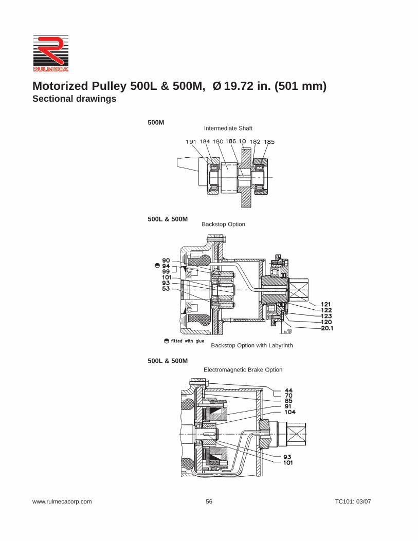
www.rulmecacorp.com TC101: 03/0756
Intermediate Shaft
Backstop Option
Backstop Option with Labyrinth
500L & 500M
500L & 500M
500M
Electromagnetic Brake Option
Motorized Pulley 500L & 500M, Ø 19.72 in. (501 mm)Sectional drawings

www.rulmecacorp.com TC101: 03/0757
1 A dimension is outer diameter of unlagged pulley shell at pulley centerline.2 B dimension is outer diameter of unlagged pulley shell at each end of shell.3 Idler pulley shown is non-crowned version.4 D dimension is shaft diameter.
Motorized Pulley with terminal box
Idler Pulley3
UT500H
Mounting bracket*
Motorized Pulley or Idler Pulley
Motorized Pulleys Material Bracket Dimensions Weight& Idler Pulleys Size* D I S V W W1 W2 X X1 Z Z1Model in in in in in in in in in in in lbs
500H & UT500H Cast iron AL65 / ALO65 2.56 4.53 0.91 1.34 1.85 3.54 2.36 7.09 9.45 3.15 5.55 17.64
A B C D4 E G L M O P
Model in in in in in in in in in in
500H 19.72 19.57 – 2.56 7.56 3.74 3.94 1.44 6.14 5.91
UT500H 19.72 19.72 – 2.56 9.25 3.74 – – – 5.91
Motorized Pulley 500H, Ø 19.72 in. (501 mm)
* Type AL bracket has gib key. Type ALO has no gib key. See position 69 on page 68.
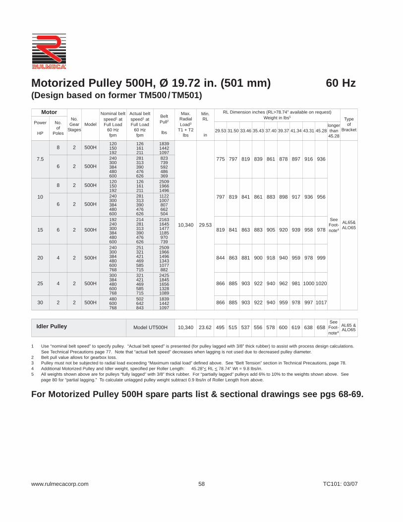
www.rulmecacorp.com TC101: 03/0758
Motorized Pulley 500H, Ø 19.72 in. (501 mm) 60 Hz(Design based on former TM500 /TM501)
MotorNo.
GearStages
Model
Nominal beltspeed1 atFull Load
60 Hzfpm
Actual beltspeed1 atFull Load
60 Hzfpm
BeltPull2
lbs
Max.RadialLoad3
T1 + T2lbs
Min.RL
in
RL Dimension inches (RL>78.74” available on request)Weight in lbs5 Type
ofBracket
Power
HP
No.of
Poles 29.53 31.50 33.46 35.43 37.40 39.37 41.34 43.31 45.28longerthan
45.28
7.5
8 2 500H120150192
126161211
183914421097
10,340 29.53
775 797 819 839 861 878 897 916 936
SeeFoot-note4
AL65&ALO65
6 2 500H240300384480600
281313390476626
823739592486369
10
8 2 500H120150192
126161211
250919661496
797 819 841 861 883 898 917 936 9566 2 500H
240300384480600
281313390476626
11221007807662504
15 6 2 500H
192240300384480600
214281313390476626
2163164514771185970739
819 841 863 883 905 920 939 958 978
20 4 2 500H
240300384480600768
251321421469585715
25091966149613431077882
844 863 881 900 918 940 959 978 999
25 4 2 500H300384480600768
321421469585715
24251845165613281089
866 885 903 922 940 962 981 1000 1020
30 2 2 500H480600768
502642843
183914421097
866 885 903 922 940 959 978 997 1017
Idler Pulley Model UT500H 10,340 23.62 495 515 537 556 578 600 619 638 658SeeFoot-note4
AL65 &ALO65
1 Use “nominal belt speed” to specify pulley. “Actual belt speed” is presented (for pulley lagged with 3/8” thick rubber) to assist with process design calculations.See Technical Precautions page 77. Note that “actual belt speed” decreases when lagging is not used due to decreased pulley diameter.
2 Belt pull value allows for gearbox loss.3 Pulley must not be subjected to radial load exceeding “Maximum radial load” defined above. See “Belt Tension” section in Technical Precautions, page 78.4 Additional Motorized Pulley and Idler weight, specified per Roller Length: 45.28”< RL < 78.74” Wt = 9.8 lbs/in.5 All weights shown above are for pulleys “fully lagged” with 3/8” thick rubber. For “partially lagged” pulleys add 6% to 10% to the weights shown above. See
page 80 for “partial lagging.” To calculate unlagged pulley weight subtract 0.9 lbs/in of Roller Length from above.
For Motorized Pulley 500H spare parts list & sectional drawings see pgs 68-69.

www.rulmecacorp.com TC101: 03/0759
FAM Excavator (Marl Pit in South Carolina—USA)FAM designed and built this 1,000 TPH excavator for an internationalcement producer in 2002. The 50’ long boom conveyor and 100’ long dis-charge conveyor each use a 31.5” diameter 100 HP Motorized Pulley todrive a 54” wide belt at 600 FPM. FAM has been using Rulmeca MotorizedPulleys as excavator belt drives for more than 30 years. Photo was takenduring machine commissioning.
Technical Precaution: When using a motorized pulley on an articulatingconveyor that inclines up and down use a brake to prevent material fromrolling “downhill” when conveyor stops. External brake shaft option is avail-able from Rulmeca.
Mechanical Excavator Reclaimer (Allouez Dock—Superior, Wisconsin)Photo shows one of three 40 year old bucket wheel reclaimers upgraded atrail to ship transfer facility by BNSF. In 2004 tandem 120 HP RulmecaMotorized Pulleys (in a “Nested Dual Drive”) replaced original 200 HP tailconveyor drive and a single 120 HP Motorized Pulley replaced originalboom conveyor drive on machine shown. Only minor structural modifica-tions were required. On-board diesel engines were also replaced duringupgrade to provide 460V/3ph/60 Hz power supply to Motorized Pulleys.Each of three bucket wheel reclaimers now handles 4,000 TPH of taconitepellets on 54” wide belts at a speed of 768 FPM.
Technical Precaution: When using labyrinth seals periodically purge greasethrough seals to prevent grease-born grit from attacking rubber oil seals.
DEMAG Reclaimer (Taconite Ship Loading Terminal in Michigan—USA)Demag designed and built this 5,000 TPH reclaimer in 1967. Terminal oper-ator replaced original motorized pulleys with 40” diameter Rulmeca Motor-ized Pulleys in 1985. A 150 HP Motorized Pulley drives the 60’ long 72” wideboom belt at 600 FPM. A 200 HP motorized pulley drives the 75’ long 72”wide discharge conveyor at 600 FPM. Since the 1985 conversion RulmecaMotorized Pulleys have moved more than 150 million tons of taconite pelletsthrough the reclaimer.
Technical Note: Rulmeca supplies parts and service for 40” diameter Motor-ized Pulleys up to 200 HP. However, the current portfolio does not includethis model. Research and development aimed at producing Motorized Pul-leys more powerful than 180 HP is currently underway.
German Reclaimer (Taconite Mine in Vitoria—Brazil)Brazilian taconite processing plant operator replaced the 1963-vintagemotorized pulleys on boom and discharge conveyor belts with new Rulme-ca 31.5” diameter 100 HP Motorized Pulleys in 2001. Because of the abra-sive nature of taconite ore dust, the operator used labyrinth seal option tomaximize oil seal life.
Technical Precaution: When using labyrinth seals periodically purge greasethrough seals to prevent grease-born grit from attacking rubber oil seals.
Motorized PulleysBucket Wheel Excavators & Reclaimers

www.rulmecacorp.com TC101: 03/0760
Motorized Pulley 630M & 630H, Ø 24.80 in. (630 mm)Our 24.80” diameter Motorized Pulleyrange offers two differentperformance levels for BULKapplications:
- M for Medium duty- H for Heavy duty
It is important to note the productdifferences and choose theappropriate pulley based onestimated belt tension (radial load.)See page 78. The actual radial loadmust be less than the maximumallowable radial load shown in thiscatalog.
Be aware of increased belt tensions required to drive multi-plythick heavy belts and/or larger beltwidths.
If the 24.80” diameter model is notstrong enough to resist estimatedbelt tension, then select 31.50”diameter model.
M for Medium dutyA solid 2-stage gearbox enables the630M to handle irregular loadings inharsh operating conditions. 630Muses motor and gearbox from 500H.Note that 630M outer dimensions donot match 630HH for Heavy duty630H has stronger internalcomponents with gearbox, shaft, andbearings designed for tough,irregular, and extreme operatingconditions.
STANDARD SPECIFICATIONof Motorized Pulley
• Crowned mild steel 24.80” diametersteel shell painted yellow at a minimumthickness of 2.4 mils
• Bolted powder coated cast iron bearinghousings and covers, all painted yellowat a minimum thickness of 2.4 mils
• Mild steel shafts• Shaft sealing system - degree of pro-
tection IP66/67 (EN60034-5.) Seepage 88.
• Cast iron terminal box for painted yel-low at min.thickness of 2.4 mils
• 3-phase induction motors with thermalprotector
• Voltage: All common voltages avail-able. Please specify.
• Motor winding insulation Class F• Dynamically balanced rotor• Two oil plugs each fitted with a magnet
to filter the oil• Yellow painted mounting brackets (AL
& ALO) included with pulley• Oil change recommended every
10,000 operational hours• Minimum RL. Refer to pages 63• Maximum RL - Please inquire• Non standard RL’s available• To be used in horizontal positions ±5
degree only
Please note:
• Noise-sensitive Areas: High speed 2-pole motors can cause higher noiselevels and are not recommended fornoise-sensitive areas
• Technical Precautions for Design,Installation, and Maintenance:pages 76-86
• Environmental Considerations:page 72
• Optional Extras: page 61 and backcover
• Electrical Connection Diagrams:pages 94-96.
SEMI-RUST-FREE options
TS11• Painted mild steel shell at minimum
thickness of 4.7 mils• Painted cast iron end housings at mini-
mum thickness of 4.7 mils• Stainless steel bearing covers with
labyrinth grooves – AISI 304 range• Nitrided shaft sleeves• Zinc-plated oil plugs - each with mag-
net• Zinc-plated exterior bolts • Shaft sealing system – degree of pro-
tection P66/67 (EN60034-5) See pg 88.• Painted terminal box at minimum thick-
ness of 4.7 mils• Nickel plated mounting brackets with
labyrinth grooves
TS12• As TS11, but without regreasable
seals.• Covers - standard
Please note:
• FDA & USDA food grade recognized oiland grease are not included in TS11 &TS12, but available on request.
Please specify required TS numberwhen ordering Stainless Steeloptions.

www.rulmecacorp.com TC101: 03/0761
OPTIONAL EXTRASMotorized Pulley 630M & 630H
x = Optional extraso = An option with certain limitations. Please refer to Technical precautions pages 76-86!Std. = Fitted as standard
Specification Availability
Semi-rust-free option TS11 with regreasable labyrinth seals xSemi-rust-free option TS12 with standard seals xRegreasable labyrinth seals xDust explosion proof Motorized Pulleys - ATEX 95 - Zone 22 - for applications handling of dusty grain etc. According to European Directive 94/9/EC. xStandard black rubber lagging (See page 80.)
3/8” full smooth lagging - Hardness 60 ±5 Shore A o3/8” full diamond lagging - Hardness 60 ±5 Shore A o3/8” partial smooth lagging - Hardness 60 ±5 Shore A o
White smooth rubber lagging (FDA listed) - Oil, fat & grease resistant oSpecial lagging - e.g. hot vulcanized, partial, and ceramic (See page 80.) oExternal brake shaft (for mechanical brake by others) xMechanical backstop Min. RL = 29.53” for 630M x
Min. RL = 37.40” for 630H xInsulation class F with standard oil: (allowable ambient temperature: -13°F/+104°F) Std.Insulation class H with synthetic oil: (allowable ambient temperature: -13°F/+120°F) xParallel shell xThermal protector Std.Voltage: Single voltage (460) stator (Y winding) wired for 460v/3ph/60 Hz at terminal box Std.IP66/67 Standard yellow powder coated cast iron terminal box Std.Special voltage motors xCSA approved motors x

www.rulmecacorp.com TC101: 03/0762
Motorized Pulley with terminal box
Idler Pulley3
UT500H / UT502H
Mounting brackets*
Motorized Pulleys or Idler Pulleys
Motorized Pulleys Material Bracket Dimensions Weight& Idler Pulleys Size* D I S V W W1 W2 X X1 Z Z1Model in in in in in in in in in in in lbs
630M & UT500H Cast iron AL65 / ALO65 2.56 4.53 0.91 1.34 1.85 3.54 2.36 7.09 9.45 3.15 5.55 17.64630H & UT502H Cast steel AL90 / ALO90 3.54 6.30 1.02 1.65 2.40 4.61 3.15 9.84 12.60 3.94 7.20 41.89
A B C D4 E G L M O PModel in in in in in in in in in in
630M 24.80 24.65 - 2.56 7.56 3.74 3.94 1.42 6.14 5.91630H 24.80 24.65 - 3.54 10.55 3.46 6.50 2.13 9.06 5.91UT500H 19.72 19.72 - 2.56 9.25 3.74 - - - 5.91UT502H 19.72 19.72 - 3.54 8.90 3.35 - - - 5.91
Motorized Pulley 630M & 630H, Ø 24.80 in. (630 mm)
* Type AL bracket has gib key. Type ALO has no gib key. See position 69 on page 68.
1 A dimension is outer diameter of unlagged pulley shell at pulley centerline.2 B dimension is outer diameter of unlagged pulley shell at each end of shell.3 Idler pulley shown is non-crowned version.4 D dimension is shaft diameter.

www.rulmecacorp.com TC101: 03/07
1 Use “nominal belt speed” to specify pulley. “Actual belt speed” is presented (for pulley lagged with 3/8” thick rubber) to assist with process design calculations.See Technical Precautions page 77. Note that “actual belt speed” decreases when lagging is not used due to decreased pulley diameter.
2 Belt pull value allows for gearbox loss.3 Pulley must not be subjected to radial load exceeding “Maximum radial load” defined above. See “Belt Tension” section in Technical Precautions, page 78.4 Additional Motorized Pulley and Idler weight: Model 630M: 45.28”< RL < 78.74” Wt = 11.2 lbs/in; Model 630H: 51.18”< RL < 78.74” Wt = 15.8 lbs/in.5 All weights shown above are for pulleys “fully lagged” with 3/8” thick rubber. For model 630H “partially lagged” pulleys add 4% to 7% to the weights shown
above. See page 80 for “partial lagging.” To calculate unlagged pulley weight subtract 1.2 lbs/in of Roller Length from above.
63
Motorized Pulley 630M & 630H, Ø 24.80 in. (630 mm) 60 HzMotor
No.Gear
StagesModel
Nominal beltspeed1 atFull Load
60 Hzfpm
Actual beltspeed1 atFull Load
60 Hzfpm
BeltPull2
lbs
Max.RadialLoad3
T1 + T2lbs
Min.RL
in
RL Dimension inches (RL>78.74” available on request)Weight in lbs5 Type
ofBracket
Power
HP
No.of
Poles 29.53 31.50 33.46 35.43 37.40 39.37 41.34 43.31 45.28longerthan
45.28
7.5
8 2 630M150192240
157200267
14731155866
10,300 29.53
907 929 951 972 994 1019 1041 1064 1086
SeeNote4
AL65 &ALO65
6 2 630M300384480600768
351390487594782
659591475388296
10
8 2 630M150192240
157200267
200915741181
927 949 970 992 1014 1039 1061 1084 11066 2 630M
300384480600768
351390487594782
899807647530404
15 6 2 630M
240300384480600768
267351390487594782
173313181183949777591
960 982 1006 1027 1049 1074 1096 1119 1141
20 4 2 630M
300384480600768
313401526586730
2003157411991075863
984 1006 1030 1052 1074 1099 1120 1143 1165
25 4 2 630M384480600768
400526586730
1959147813271064
1006 1028 1052 1074 1096 1121 1142 1165 1187
30 2 2 630M 600768
627800
14731155 1006 1028 1052 1074 1096 1121 1142 1165 1187
MotorNo.
GearStages
Model
Nominal beltspeed1 atFull Load
60 Hzfpm
Actual beltspeed1 atFull Load
60 Hzfpm
BeltPull2
lbs
Max.RadialLoad3
T1 + T2lbs
Min.RL
in
RL Dimension inches (RL>78.74” available on request)Weight in lbs5 Type
ofBracket
Power
HP
No.of
Poles 37.40 39.37 41.34 43.31 45.28 47.24 49.21 51.18longerthan
51.18
30 8 2 630H
240300384480600768
247314408492639783
374529462268187914491182
16,600 37.40 1819 1850 1879 1910 1939 1963 1995 2025
SeeNote4
AL90 &ALO90
40 8 2 630H
240300384480600768
247314408492639783
510740183093256319751611
22,000 37.40 1863 1894 1923 1955 1983 2007 2039 2069
50 6 2 630H300384480600768
330418544656851
47233717286123701828
22,000 37.40 1863 1894 1923 1955 1983 2007 2039 2069
61 4 2 630H480600768960
493627815984
3830301323211922
19,900 37.40 1907 1939 1967 1999 2027 2051 2083 2114
75 4 2 630H600768960
627815984
368328362349
19,900 37.40 1907 1919 1967 1999 2027 2051 2083 2114
Idler Pulley Model UT500H 10,300 29.53 578 600 638 658 677 697 716 735See
Note4AL65 &ALO65
Model UT502H 22,000 29.53 669 691 711 733 753 775 797 818

www.rulmecacorp.com TC101: 03/0764
Our 31.50” diameter Motorized Pulleyrange offers two differentperformance levels for BULKapplications:
- M for Medium duty- H for Heavy duty
It is important to note the productdifferences and choose theappropriate pulley based onestimated belt tension (radial load.)See page 78. The actual radial loadmust be less than the maximumallowable radial load shown in thiscatalog.
Be aware of increased belt tensions required to drive multi-plythick heavy belts and/or larger beltwidths.
If the 800M is not strong enough toresist estimated belt tension, thenselect 800H.
M for Medium dutyA solid 2-stage gearbox enables the800M to handle irregular loadings inharsh operating conditions. 800Muses motor and gearbox from 630H.Note that 800M outer dimensions donot match 800HH for Heavy duty800H has stronger internalcomponents with gearbox, shaft, andbearings designed for tough,irregular, and extreme operatingconditions.
STANDARD SPECIFICATIONof Motorized Pulley
• Crowned mild steel 31.50” diametersteel shell painted yellow at a minimumthickness of 2.4 mils
• Bolted powder coated cast iron bearinghousings and covers, all painted yellowat a minimum thickness of 2.4 mils
• Mild steel shafts• Shaft sealing system - degree of pro-
tection IP66/67 (EN60034-5.) Seepage 88.
• Cast iron terminal box for painted yel-low at min.thickness of 2.4 mils
• 3-phase induction motors with thermalprotector
• Voltage: All common voltages avail-able. Please specify.
• Motor winding insulation Class F• Dynamically balanced rotor• Two oil plugs each fitted with a magnet
to filter the oil• Yellow painted mounting brackets (AL
& ALO) included with pulley• Oil change recommended every
10,000 operational hours• Minimum RL. Refer to pages 67• Maximum RL - Please inquire• Non standard RL’s available• To be used in horizontal positions ±5
degree only
Please note:
• Noise-sensitive Areas: High speed 2-pole motors can cause higher noiselevels and are not recommended fornoise-sensitive areas
• Technical Precautions for Design,Installation, and Maintenance:pages 76-86
• Environmental Considerations:page 72
• Optional Extras: page 65 and backcover
• Electrical Connection Diagrams:pages 94-96.
SEMI-RUST-FREE options
TS11• Painted mild steel shell at minimum
thickness of 4.7 mils• Painted cast iron end housings at mini-
mum thickness of 4.7 mils• Stainless steel bearing covers with
labyrinth grooves – AISI 304 range• Nitrided shaft sleeves• Zinc-plated oil plugs - each with mag-
net• Zinc-plated exterior bolts • Shaft sealing system – degree of pro-
tection P66/67 (EN60034-5) See pg 88.• Painted terminal box at minimum thick-
ness of 4.7 mils• Nickel plated mounting brackets with
labyrinth grooves
TS12• As TS11, but without regreasable
seals.• Covers - standard
Please note:
• FDA & USDA food grade recognized oiland grease are not included in TS11 &TS12, but available on request.
Please specify required TS numberwhen ordering Stainless Steeloptions.
Motorized Pulley 800M & 800H, Ø 31.50 in. (800 mm)

www.rulmecacorp.com TC101: 03/0765
OPTIONAL EXTRASMotorized Pulley 800M & 800H
x = Optional extraso = An option with certain limitations. Please refer to Technical precautions pages 76-86Std. = Fitted as standard
Specification Availability
Semi-rust-free option TS11 with regreasable labyrinth seals xSemi-rust-free option TS12 with standard seals xRegreasable labyrinth seals xDust explosion proof Motorized Pulleys - ATEX 95 - Zone 22 - for applications handling of dusty grain etc. According to European Directive 94/9/EC. xStandard black rubber lagging (See page 80.)
3/8” full smooth lagging - Hardness 60 ±5 Shore A o3/8” full diamond lagging - Hardness 60 ±5 Shore A o3/8” partial smooth lagging - Hardness 60 ±5 Shore A o
White smooth rubber lagging (FDA listed) - Oil, fat & grease resistant oSpecial lagging - e.g. hot vulcanized, partial, and ceramic (See page 80.) oExternal brake shaft (for mechanical brake by others) xMechanical backstop Min. RL = 37.40” for 800M x
Min. RL = 45.28” for 800H < 100 HP x Min. RL = 55.12” for 800H > 100 HP x
Insulation class F with standard oil: (allowable ambient temperature: -13°F/+104°F) Std.Insulation class H with synthetic oil: (allowable ambient temperature: -13°F/+120°F) xParallel shell xThermal protector Std.Voltage: Single voltage (460) stator (Y winding) wired for 460v/3ph/60 Hz at terminal box Std.IP66/67 Standard yellow powder coated cast iron terminal box Std.Special voltage motors xCSA approved motors x

www.rulmecacorp.com TC101: 03/0766
Motorized Pulley with terminal box
Idler Pulley3
UT630M / UT630H
Motorized Pulleys or Idler Pulleys
Motorized Pulleys Material Bracket Dimensions Weight& Idler Pulleys Size* D I S V W W1 W2 X X1 Z Z1Model in in in in in in in in in in in lbs
800M & UT630M Cast steel AL90/ALO90 3.54 6.30 1.02 1.65 2.40 4.61 3.15 9.84 12.60 3.94 7.20 41.89800H & UT630H Cast steel AL120/ALO120 4.72 7.87 1.30 1.97 3.74 6.30 4.72 11.81 14.57 4.33 8.39 83.78
A B C D4 E G L M O PModel in in in in in in in in in in
800M 31.50 31.34 - 3.54 10.55 3.46 6.50 2.13 9.06 5.91800H 31.50 31.34 - 4.72 12.99 3.15 7.87 2.44 10.24 5.91UT630M 24.80 24.80 - 3.54 8.90 3.35 - - - 5.91UT630H 24.80 24.80 - 4.72 12.99 2.95 - - - 5.91
Motorized Pulley 800M & 800H, Ø 31.50 in. (800 mm)
* Type AL bracket has gib key. Type ALO has no gib key. See position 69 on page 68.
1 A dimension is outer diameter of unlagged pulley shell at pulley centerline.2 B dimension is outer diameter of unlagged pulley shell at each end of shell.3 Idler pulley shown is non-crowned version.4 D dimension is shaft diameter.
Mounting brackets*

www.rulmecacorp.com TC101: 03/07
1 Use “nominal belt speed” to specify pulley. “Actual belt speed” is presented (for pulley lagged with 3/8” thick rubber) to assist with process design calculations.See Technical Precautions page 77. Note that “actual belt speed” decreases when lagging is not used due to decreased pulley diameter.
2 Belt pull value allows for gearbox loss.3 Pulley must not be subjected to radial load exceeding “Maximum radial load” defined above. See “Belt Tension” section in Technical Precautions, page 78.4 Additional Motorized Pulley weight: Model 800M: 53.15”< RL < 78.74” Wt = 16.1 lbs/in; Model 800H & 800HD: 66.93”< RL < 78.74” Wt = 31.5 lbs/in.
Additional Idler Pulley weight: Model UT630M: 53.15”< RL < 78.74” Wt = 11.2 lbs/in; Model UT630H: 66.93”< RL < 78.74” Wt = 18.0 lbs/in.5 All weights shown above are for pulleys “fully lagged” with 3/8” thick rubber. For “partially lagged” model 800M pulleys add 5% to 8% (for 800H pulleys add 3%
to 4%) to the weights shown above. See page 80 for “partial lagging.” To calculate unlagged pulley weight subtract 0.9 lbs/in of Roller Length from above.
* Special “Short Roller Length” Option.** Available September 2007.
67
Motorized Pulley 800M, 800H, 800HD, Ø 31.50 in. (800 mm) 60 HzMotor
No.Gear
StagesModel
Nominal beltspeed1 atFull Load
60 Hzfpm
Actual beltspeed1 atFull Load
60 Hzfpm
BeltPull2
lbs
Max.RadialLoad3
T1 + T2lbs
Min.RL
in
RL Dimension inches (RL>78.74” available on request)Weight in lbs5 Type
ofBracket
Power
HP
No.of
Poles 37.40 39.37 41.34 43.31 45.28 47.24 49.21 51.18 53.15longerthan
53.15
30 8 2 800M300384480600768
312396515621806
29662333179714891148
16,500 37.40 2118 2150 2179 2211 2241 2266 2291 2323 2354
SeeNote4
AL90 &ALO90
40 8 2 800M300384480600768
312396515621806
40453182245120301565
22,000 37.40 2207 2239 2268 2300 2329 2354 2379 2411 2443
50 6 2 800M384480600768960
416528686828
1075
37412944226718771448
22,000 37.40 2207 2239 2268 2300 2329 2354 2379 2411 2443
61 4 2 800M600768960
614786983
303423861838
19,900 37.40 2251 2282 2312 2343 2373 2398 2423 2455 2486
Idler PulleyModel UT630M 22,000 29.53 765 788 810 832 852 874 897 919 941 See
Note4AL90 &ALO90Model UT630H 45,000 45.28 1608 1643 1678 1713 1749 1784 1819 1854 1889
MotorNo.
GearStages
Model
Nominal beltspeed1 atFull Load
60 Hzfpm
Actual beltspeed1 atFull Load
60 Hzfpm
BeltPull2
lbs
Max.RadialLoad3
T1 + T2lbs
Min.RL
in
RL Dimension inches (RL>78.74” available on request)Weight in lbs5 Type
ofBracket
Power
HP
No.of
Poles 55.12 57.09 59.06 61.02 62.99 64.96 66.93 68.90 70.87longerthan
70.87
75
** 3 800HD192240300
** ** ** 51.18* * * * ** ** ** ** ** **
SeeNote4
AL90 &ALO90
8 2 800H 384 380 6087
45,000
55.12
4823 4881 4939 4997 5055 5114 5172 5230 52886 2 800H480600768960
1064
507617740879
1036
45653749312426302231
45.28
100
8 3 800HD 240 ** ** ** 61.02 - - - ** ** ** ** ** **6 300 ** ** 51.18* * * * ** ** ** ** ** **8 2 800H 384 380 8300
45,000
55.12
4823 4881 4939 4997 5055 5114 5172 5230 52886 2 800H480600768960
1064
507617740879
1036
62265111426035873043
45.28
122
** 3 800HD 300384 ** ** ** 61.02 - - - ** ** ** ** ** **
6 2 800H480600768960
1064
507617740879
1036
74706134511143053651
45,000 55.12 4933 4991 5049 5108 5166 5224 5282 5340 5398
150** 3 800HD
384480600
** ** ** 61.02 - - - ** ** ** ** ** **
4 2 800H768960
1064
7609261111
608749984165
40,500 55.12 4878 4936 4994 5052 5111 5169 5227 5285 5343
180** 3 800HD 480
600** ** ** 61.02 - - - ** ** ** ** ** **
4 2 800H768960
1064
7609261111
730459974998
40,500 55.12 4966 5024 5062 5141 5199 5257 5315 5373 5431
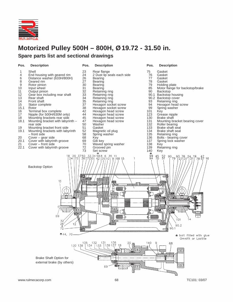
www.rulmecacorp.com TC101: 03/0768
Motorized Pulley 500H – 800H, Ø19.72 - 31.50 in. Spare parts list and sectional drawings
1 Shell4 End housing with geared rim6 Distance washer (633H/800H)8 Geared rim9 Rotor pinion
10 Input wheel11 Output pinion12 Gear box including rear shaft13 Rear shaft14 Front shaft15 Stator complete15.1 Rotor16 Terminal box complete17 Nipple (for 500H/630M only)18 Mounting brackets rear side18.1 Mounting bracket with labyrinth –
rear side19 Mounting bracket front side19.1 Mounting brackets with labyrinth
– front side20 Cover – gear side20.1 Cover with labyrinth groove21 Cover – front side22.1 Cover with labyrinth groove
23 Rear flange24 2 Dust lip seals each side26 Bearing27 Bearing30 Bearing31 Bearing32 Retaining ring33 Retaining ring34 Retaining ring35 Retaining ring37 Hexagon socket screw38 Hexagon socket screw42 Hexagon head screw44 Hexagon head screw45 Hexagon head screw47 Hexagon head screw50 Washer51 Gasket52 Magnetic oil plug58 Spring washer68 Key69 Gib key70 Waved spring washer72 Grooved pin73 Set screw
75 Gasket76 Gasket77 Gasket78 Gasket79 Holding plate85 Motor flange for backstop/brake 90 Backstop90.1 Backstop housing90.2 Backstop cover93 Retaining ring94 Hexagon head screw99 Spring washer
101 Key123 Grease nipple130 Brake shaft131 Mounting bracket bearing cover132 Roller bearing133 Brake shaft seal134 Brake shaft seal135 Retaining ring136 Bolts - bearing cover137 Spring lock washer138 Key139 Retaining ring140 Key
Backstop Option
Brake Shaft Option forexternal brake (by others)
Pos. Description Pos. Description Pos. Description

www.rulmecacorp.com TC101: 03/0769
Motorized Pulley 500H – 800H, Ø19.72 - 31.50 in. Sectional drawings
Backstop Option
Labyrinth Option
Valid for 800M & 800H

www.rulmecacorp.com TC101: 03/0770
Motorized PulleysMechanical Backstops
Sand and Gravel Pit (Texas—USA)Installed in 1994 this 12.64” diameter 7.5 HP Motorized Pulley drives the 24”wide inclined “overs belt” at 300 FPM. This conveyor stacks large unusablerocks scalped from the product stream by the primary screen at the activeface in the pit. The Motorized Pulley’s built-in mechanical backstop protectspersonnel and equipment from product “roll back” when it is necessary tostop a fully loaded belt.
Technical Precaution: It is essential that the identity of each of the three phas-es of the power supply be determined before attaching power supply wires tothe pulley to prevent the motor from driving against the backstop. The identi-ty of each of the three phases of the motor is clearly labeled.
Granite Quarry (Virginia—USA)A 20 HP 15.75” diameter Motorized Pulley elevates crushed rock 25 feet at384 FPM on the 30” wide fixed transfer conveyor at this plant (center ofphoto.) A “clockwise backstop” prevents run back of the loaded belt beltwhen power supply is off.
Technical Precaution: Direction of proper pulley rotation is indicated by analuminum arrow or plastic sticker fastened to the end housing on the terminalbox (or power cord) side of the pulley. Clockwise and counterclockwise back-stops are available. Pulley rotation is specified from the point of view of aperson looking at the pulley from the terminal box (or power cord) side of thepulley. Rotation direction is to be specified when placing order
Mechanical Backstop and Rear Flange DesignDrawing shows Motorized Pulley mechanical backstop (for models 400M -500M) keyed to motor rotor shaft and bolted to motor stator frame. Note thatmechanical backstop option requires an extended rear flange (and largerminimum Roller Length) for certain models.
Models 138E - 320L use a one-way motor rotor bearing in a standard motorstator and do not require an extended rear flange. Models 320M - 500M adda backstop to the stator within an extended rear flange, as shown. Models500H - 800H add a backstop to the stator within a standard rear flange.
Mechanical Backstop Exploded ViewRulmeca’s mechanical backstops are built into the Motorized Pulley to limitpulley rotation to one direction (either clockwise or counterclockwise.) Thebackstop’s keyed inner race is fixed to the motor rotor and the outer race isbolted to the motor stator frame.
Fixing the backstop to the motor rotor shaft, on the input side of the internalgearbox, yields two advantages: (1.) the backstop has all of the mechanicaladvantage, which can be as high as 100:1, and (2.) it is protected in a her-metically sealed environment. On the other hand, an exposed backstopcoupled to a live pulley shaft has no mechanical advantage (and must bemuch larger) and is exposed to the environment.

www.rulmecacorp.com TC101: 03/0771
Marl Pit at Cement Plant (South Carolina—USA)Installed by FAM in 2002, this crawler-mounted bucket wheel machine exca-vates marl at a rate of 1,000 TPH. It uses tail-mounted 31.5” diameter 100HP Motorized Pulleys to drive the 54” wide boom and tail conveyor belts at600 fpm. FAM specified Rulmeca Motorized Pulleys with “external brakeshaft option” because both conveyors can articulate +/- 16º and mechanicalbackstops could not be used..” Externally mounted brakes (by others) pre-vent material from “rolling backwards”when conveyors are stopped.
Technical Precaution: Control circuit must be designed so that motor andbrake never work against each other. Brake should never be clamped shutwhen motor is on except for “emergency stop.” Motor should never be pow-ered on (including “jog” command) when the brake is clamped shut.
Rulmeca Internal BrakeRulmeca internal brake is designed to function primarily as a belt holdingdevice for reversing and/or articulating conveyors. The brake is not intend-ed to be a conveyor stopping device. The brake’s keyed spline is fixed tothe motor rotor and the brake’s housing is bolted to the motor stator frame.
Fixing the brake to the motor rotor shaft, on the input side of the internalgearbox, yields two advantages: (1.) the brake has all of the mechanicaladvantage, which can be as high as 100:1, and (2.) it is protected in a her-metically sealed environment.
Rulmeca Internal Brake/Motor/Gearbox AssemblySpring-loaded electromagnetic brakes are designed to release when power isapplied to the brake coil. This is a “fail safe” feature. They clamp shut whenbrake power is removed (either during normal operation or during an emer-gency loss of overall system power.) Photo shows 320H model. Note that thisoption requires additional internal space and larger minimum Roller Length.
Technical Precaution: Control circuit for motor and brake must be designed tostop pulley motor before brake clamps shut and start pulley motor after brakeis released. Brakes are DC-powered and supplied with AC to DC rectifiers tobe mounted in a remote panel (by others). Control circuit must be designedto kill motor power in the event of loss of brake power. If this provision is notmade, motor can possibly “power through” clamped brake.
Example of External Brake (South Carolina—USA)Available in models 500H and larger, Rulmeca external brake shaft optionextends motor rotor shaft through hole in non-rotating pulley shaft for attach-ment of external brake (by others.) This hydraulically-actuated double-shoebrake (protective cover removed for photograph) prevents conveyor rollback when fully loaded belt is stopped.
The external brake option provides one of the two key advantages availablewith the internal brake option. Brake has all of the mechanical advantage ofthe drive (as high as 100:1 ratio) because it is fixed directly to the motor rotorshaft. It is, however, exposed to the environment.
Motorized PulleysInternal and External Brakes

www.rulmecacorp.com TC101: 03/07
higher ambient temperature conditionscontact Rulmeca. See page 77, 78, & 91.
High Duty Cycle (FrequentStart/ Stops)
Standard Rulmeca Motorized Pulleys aresuitable for frequent starting and stop-ping, without the use of soft start devices,as shown above. More frequentstarts/stops are possible through the useof optional special pulley constructionand/or soft starters. Contact Rulmeca fordetails. See page 79.
Impact LoadingConveyors subject to frequent impactloading (i.e. non-continuous materialflow) may require higher motor power andstronger gearbox than indicated by “con-tinuous flow” belt pull calculations. Con-tact Rulmeca. See page 78, 82, & 83.
Indexing (Induction) Conveyors
Electromagnetic brake provides excellentproduct “hold” capability in induction sys-tems requiring “indexing.” See page 79.
72
Applications in Special Environmental ConditionsAbrasive, Wet, High HumidityEnvironments
Hermetically sealed carbon steel tubeand end housings with standard paint aresuitable for most bulk applications. How-ever, aggressive environments mayrequire regreasable seals, special finish,or stainless steel. See pages 83 - 85.
Articulating Conveyors Electromagnetic brakes or external brakeshafts for brakes (by others) provide suit-able material “holdback” capability forarticulating conveyors. Mechanical back-stops will not work in this applicationbecause these conveyors elevate andlower material. See pages 70, 71, 79 &81.
Chemical/Corrosive Environ-mentsaggressive environments may requireregreasable seals, special lagging mate-rial, special finish, or stainless steel. Seepages 80, 81, and 83 - 85.
Critical Speed RequirementsActual belt speed is a function of motorpole number, gear ratio, and load. Thiscatalog displays actual full load belt speedof an unlagged Motorized Pulley at nomi-nal voltage and 60 Hz to assist designerswho need precise belt speeds. See page77.
Dust & Gas EnvironmentsRulmeca Motorized Pulleys with IP67sealing are available with optional certifi-cation for service in an ATEX 95 Class II(“dust explosion proof”) Zone 22 atmos-
phere, according to European UnionDirective 94/9EC article 8. Note that Rul-meca Motorized Pulleys are not “intrinsi-cally safe” or “flame proof” and are notsuitable for service in: Class I (gasses,vapors, & liquids), Class II Zone 20, orClass II Zone 21 environments. ContactRulmeca for additional details.
Elevating ConveyorsMechanical backstops provide suitablematerial “holdback” capability for fixedposition, non-reversing, inclined convey-ors. See pages 70 & 81.
Food Handling
Regreasable seals, full stainless steel,and food grade oil, grease, and laggingmaterial are suitable for this environment,which usually includes frequent highpressure/chemical wash down. Seepages 80, 84, & 85.
High Altitude >3,300 ft AboveSea Level (ASL)Standard Rulmeca Motorized Pulleysprovide suitable performance in moun-tainous areas. When specifying motorpower derate by 2.5% for elevations of3,300-5,000’ ASL and 5% for elevationsof 5,000-6,600’ ASL. Contact Rulmecafor assistance with higher elevations.
High Ambient TemperatureStandard Rulmeca Motorized Pulleyswith Class F motor and standard oil aresuitable for use in a maximum ambienttemperature of 104 oF. Optional Motor-ized Pulleys with Class H motor and syn-thetic oil are suitable for use in a maxi-mum ambient temperature of 120 oF. For
Model Max. No. of Start/stops
138E 240 per hour165E 180 per hour220M & 220H 120 per hour320L, 320M & 320H,400L, 400M & 400H 25 per hour500L, 500M, 500H, 630M & 630H,800M & 800H 10 per hour

www.rulmecacorp.com TC101: 03/07
Non-belt ApplicationsSpecial Motorized Pulley designs areavailable for “non-belt, V-belt, partialbelt, and modular belt” applications. It isessential that each special applicationbe designed to adequately dissipateheat from the pulley surface. ContactRulmeca for assistance with these appli-cations. See pages 77, 78, & 83.
Non-horizontal Mounting (i.e.between 5° - 90° and Vertical)
Certain applications (e.g. self-cleaningelectromagnet for tramp iron, picturedabove, “tilted” package sortation convey-ors, and “travelling wall”) require pulleyshaft to be mounted out of the horizontalplane. This Motorized Pulley optionrequires extra oil, grease packed topbearing, and special electrical termina-tion. Contact Rulmeca for assistance.see pages 82, 83, and 91.
Oily, Greasy, & Fatty Materials
Environments with high amounts oil,grease, and/or fat require special oil-resistant lagging. If they require frequenthigh pressure and/or chemical cleaningthey may also require regreasable sealsand stainless steel or special surfacecoating. See pages 80, 84, & 85.
Reversible ConveyorsAll standard three-phase Rulmeca Motor-ized Pulleys are suitable for use in revers-ing conveyors. However, motor controlcircuit must be designed to bring pulley toa complete stop before reversing direc-tion. See pages 84 & 85.
Starting Under LoadAll Rulmeca Motorized Pulley motors are“Design C” and developed for direct start-ing. They provide 200% start-up torquewhen started directly. To reduce inrush(start-up) current it is possible to usestarting device such as soft starter or vari-able frequency drive. Note that thesedevices typically reduce start-up torque to150% of running torque. See pages 81 &86.
Underground Tunneling & Min-ing Applications
Rulmeca Motorized Pulleys have beenincorporated into Tunnel BoringMachines (pictured above) for years.However, they are not “intrinsically safe”or “flame proof” and are not suitable forservice where explosive gasses, vapors,liquids, or dust are continuously present.Contact Rulmeca for additional details.
Underwater applicationsThe Rulmeca Motorized Pulley IP67 seal-ing system has been successfully testedfor 30 minutes under 1 m of water. How-ever, the motor is not intended for contin-uous underwater service.
Variable Speed ConveyorTwo speed motor. AC frequency convert-er.
73
Low Ambient TemperatureRulmeca Motorized Pulleys with standardmotor and oil are suitable for use in aminimum ambient temperature of -13°F.Optional food grade oil lowers the pulleyoperating temperature range to a mini-mum of -22°F. Contact Rulmeca for loweroperating temperatures. Special oil, spe-cial seals, and internal anti-condensationheater may be required. See pages 77,78, & 91.
Marine Environment
Corrosive ocean environment oftenrequires regreasable sealing system,stainless steel or special surface finish.See pages 83 - 85.
Noise-Sensitive Environments
In noise-sensitive areas (e.g. locationswhere public access to conveyors is per-mitted) certain Motorized Pulley designrestrictions apply. Contact Rulmeca forspecial oil viscosities and quantities, spe-cially balanced pulleys, and when toavoid the use of 2 pole motors.
Applications in Special Environmental Conditions

www.rulmecacorp.com TC101: 03/07
IntroductionDesigners should use the following engi-neering principles in selecting the optimalbelt conveyor drive for bulk handlingapplications. Refer to the latest edition of“Belt Conveyors for Bulk Materials,” pub-lished by the Conveyor Equipment Manu-facturers Association (CEMA) for a com-prehensive design guide.
Design ParametersDetermine desired design parameters:• product flow rate (Q)• belt speed (V)• belt width (w)• conveyor length (L)• product size• lift height (H)• type & thickness of belt• type of belt support
Make the following control choices:• continuous or intermittent flow• fixed or variable belt speed• conveyor duty cycle• extremes of process flow• ambient environment extremes• applicable safety requirements
Optimize Belt Speed & BeltWidthSelect Belt Width:• with bulk density & belt speed fixed,
select width to yield product flow rate,not exceeding CEMA “standard edgedistance”
• width must be > 3x max lump for 20 o
surcharge and > 6x max lump for 30 o
surcharge • width must be wide enough to prevent
loading chute and skirtboard jamming(i.e. > 3x to 5x max lump)
Select Belt Speed:• with bulk density & width fixed, select
speed to yield product flow rate, notexceeding CEMA “standard edge dis-tance”
• for dusty material, select speed to min-imize fugitive emissions
• for heavy sharp material, select speedto protect belt and chute lining
Calculate Power to Drive BeltCEMA has empirically developed a vari-ety of factors to simply the determinationof belt pull. Some of these factorsinclude: idler roller bearing friction (Kx,)belt and load flexure resistance (Ky,) andskirtboard friction (Tsb.) To determinerequired HP calculate required belt pull atspecified belt speed as follows:• with belt width and speed fixed, select
conveyor components and calculatebelt tension (Te) required to overcomegravity, friction, and momentum using:Te = LKt (Kx + KyWb + 0.015Wb) + Wm (LKy + H) + Tp + Tam + Tac
• calculate power required to drive beltusing:HP = (TeV) / 33,000
Go to www.rulmecacorp.com for free“downloadable” conveyor design soft-ware incorporating equations above anda complete set of definitions for all perti-nent terminology.
Select Drive & Check GeometryFinally, select conveyor drive and checkdesign using final parameters as follows:• select Motorized Pulley to match
design belt speed and required HP• check selected pulley diameter verify-
ing that wrap factor and belt life areacceptable
• recalculate required belt pull and HPusing selected “actual belt speed”
• check material cross section on beltverifying that edge distance is accept-able
• check material trajectory verifying thattransfer chute will not plug and materi-al will drop at desired location
Go to www.rulmecacorp.com for free“downloadable” conveyor design soft-ware incorporating material cross sectionand trajectory plotting programs and pul-ley diameter check.
Special Loading ConditionsCertain loading are beyond the scope ofthe 5th Edition of the CEMA manual.
These include:• hopper feeder conveyors• slider bed conveyor supports• cleated and/or sidewall beltGo to www.rulmecacorp.com for free“downloadable” conveyor design soft-ware incorporating HP calculations forthese special conditions.
ExamplesThe drawings below were generated byRulmeca design software and illustratehow the programs can help designersavoid errors.
Trajectory plot shows that slower beltspeed (solid line) will not plug chute whilefaster belt speed (dotted line) will. This isbecause trajectory of center of materialmass impacts against vertical chute wallabove horizontal centerline of pulley.
Plot shows that selected belt speed (dot-ted line) may cause material spillagebecause cross section exceeds CEMArecommendation (solid line.)
74
Bulk Materials Handling Engineering Principles

www.rulmecacorp.com TC101: 03/07
Standard Loading Conditions:Conveyor Length (ft) ____Tonnage Rate (tph) ____Belt Speed (fpm) ____Material Lift Height (ft) ____Ambient Temperature (oF) Min ____Ambient Temperature (oF) Max ____Initial Velocity of Material (fpm) ____Number of Belt Cleaners ____Number of Belt Plows ____Length of Skirt Zone (ft) ____Depth of Material in Skirt Zone (in) ____Number of Non-driven Pulleys ____
Operating Conditions:Duty Cycle (Start/stops per hour) ____Hours of Operation (hrs/day) ____Days of Operation (days/week) ____Is this a reversing belt? ____Additional Comments: ______________________________________________________________________________________________________________
Special Loading Conditions:Hopper Feeder Parameters:Hopper Opening Width (in) ____Hopper Opening Length (in) ____
Slider Bed Parameters:Slider Bed Length (ft) ____
Sidewall & Cleated Belt Parameters:Sidewall & cleat height (in) ____Thickness of sidewall (in) ____Distance between cleats (in) ____Thickness of cleats (in) ____
Tripper Design Parameters:Tripper Length (ft) ____Tripper Material Lift Height (ft) ____Number of Tripper Belt Cleaners ____Tripper Skirt Zone Length (ft) ____Depth of Material in Skirt Zone (in) ____No. of Tripper Non-driven Pulleys ____
For free “downloadable”power calculation program,complete with definitions of allterminology, go to www.rulmecacorp.com.
75
APPLICATION WORKSHEET - BULK MATERIALS HANDLINGMotorized PulleysComplete this form and submit to Rulmeca for a power calculation and Motorized Pulley recommendation.
Contact Person ____________________________ Date ______________ Ref # ________________Company __________________________________________________________________________ Address ___________________________________________________________________________Phone _______________________ Fax ______________________ Email _____________________
Belt Width (in)
182430364248546066728496
Other_____
Elevation (ft)
3,3005,0006,600
CEMAType
ABCDE
TroughingIdler Spac-
ing (ft)3.03.54.04.55.0
Angle ofWrap (deg)
180200210220240360
Type of Lag-ging
FullPartialNone
Material (frictional coefficient)
ashes, coal, dry 0.0571bauxite, ground 0.1881cement, Portland, dry 0.2120cement clinker 0.1228clay, ceramic, dry fines 0.0924coal, bituminous mined 0.0754coke, ground fine 0.0452cullet (broken glass) 0.0836grains, wheat, corn, rye 0.0433gravel, bank run 0.1145iron ore, 200 lbs/cu ft 0.2760limestone, pulverized dry 0.1280phosphate rock, dry 0.1086salt, common, dry fine 0.0814sand, dry, bank 0.1378wood chips 0.0095
Material Bulk Density (pcf)
ashes, coal, wet 50bagasse 10bark, wood 20bauxite, ground, dry 68bauxite, crushed 85beans, navy, dry 48beets, whole 48borax, 3” & under 70cement, portland 99clay, ceramic, dry, fines, 80clay, dry, fines 120coal, bituminous 55coal, lignite 45coke, 45corn, ear, 56cullet, 120gravel, bank run, 100iron ore, 200iron ore pellets 130limestone, crushed 90paper pulp stock 60phosphate rock 85potash salts 80rock, crushed, 145rock, soft, 110rye, 46sale, common dry, fine, 80sand, bank, damp, 130sand, bank, dry, 110sand, foundry, 100sawdust 13sewage sludge, moist, 55soybeans, whole, 50sugar, raw, cane, 65taconite pellets 130traprock, 2-3” lumps, 110wheat, cracked, 45wood chips 30
Type ofTake-up
AutomaticManual
Slider Bed Material (frictional coefficient)
steel 0.90UHMW polyethylene 0.545urethane 0.88wood 1.00
Type of Belt
1 ply, 160 piw2 ply, 225 piw3 ply, 330 piw4 ply, 440 piw
Belt Carcass
fabricsteel cord
Idler RollDiam. (in)
3456

www.rulmecacorp.com TC101: 03/0776
Technical Precautions for Design, Installation and MaintenanceThe precautions below will enable conveyor engineers, system integrators, and end users to properly design,install, operate, and maintain conveyor systems using Rulmeca Motorized Pulleys. Ignoring any of the pre-cautions may result in pulley damage and will void the product warranty. Precautions which could effect war-ranty coverage are marked with a warning symbol, as shown.
Use these technical precautions with the Rulmeca Bulk catalog entitled “Motorized Pulleys for belt conveyors”TC-101.
Contents Page
1 Actual Belt Speed vs. Nominal Belt Speed............................................................................................................. 772 Aftermarket Service................................................................................................................................................ 773 Ambient Temperature............................................................................................................................................. 774 Belt Alignment........................................................................................................................................................ 785 Belt Pull.................................................................................................................................................................. 786 Belt Tension............................................................................................................................................................ 787 Capacitors for Single Phase Motors....................................................................................................................... 788 Clearance............................................................................................................................................................... 789 Electrical Installation............................................................................................................................................... 79
10 Electromagnetic Brake........................................................................................................................................... 7911 High Duty Cycle...................................................................................................................................................... 7912 Lagging Limitations................................................................................................................................................ 8013 Lagging Specifications............................................................................................................................................ 8014 Mechanical Backstops............................................................................................................................................ 8115 Motor Current Overload and Overcurrent Protection............................................................................................. 8116 Motor Thermal Protection....................................................................................................................................... 8117 Motorized Pulley Mounting Orientation.................................................................................................................. 8218 Mounting Brackets.................................................................................................................................................. 8219 Non-belt, Partial Belt, Modular Belt........................................................................................................................ 8320 Oil and Oil Seal Maintenance................................................................................................................................. 8321 Pulley Diameter...................................................................................................................................................... 8422 Regreasable Labyrinth Seals................................................................................................................................. 8423 Repair and Mechanical Maintenance..................................................................................................................... 8424 Reversing Conveyors............................................................................................................................................. 8425 Surface Coating...................................................................................................................................................... 8526 Storage of Motorized Pulleys................................................................................................................................. 8527 Start-up................................................................................................................................................................... 8528 Terminal Box........................................................................................................................................................... 8529 Transport and Handling.......................................................................................................................................... 8630 Variable Frequency Drive....................................................................................................................................... 8631 International Protection (IP) Ratings...................................................................................................................... 8932 Oil Quantities.......................................................................................................................................................... 9033 Oil Specifications.................................................................................................................................................... 9134 Wiring Diagrams..................................................................................................................................................... 92-100

www.rulmecacorp.com TC101: 03/0777
1) Actual Belt Speed vs. Nominal Belt Speed: • Two key specifications for each Motorized Pulley are power (HP) and nominal belt speed, as shown on indi-
vidual specification pages in this catalog.• Nominal belt speed is a design target, providing consistent choices among all models and powers. For exam-
ple, a nominal belt speed of 300 fpm is available in most pulley models.• Actual full load belt speed is almost never exactly equal to nominal belt speed. • Actual belt speed is a function of the motor pole number, gear ratio, and load. Therefore, this catalog displays
actual full load belt speed at 60 Hz, as well as nominal belt speed, to assist designers who need more precisebelt speeds.
• Note that all belt speeds shown in this catalogue refer to unlagged pulleys because: 1. Belt speed for each model is a function of pulley diameter, 2. Pulleys are available with and without lagging, 3. Lagging changes the pulley diameter, and4. Various lagging thicknesses are available.
• Note that each Rulmeca Motorized Pulley for a three-phase power supply uses an asynchronous squirrelcage induction motor with approximately 5% slip. In a no load condition, motor RPM is nearly equal to “syn-chronous speed” RPM. The slip rate is dependent on power and design of the motor. Low powered motorshave a lower slip rate than high-powered motors. At full load, the motor RPM is approximately 5% less thansynchronous.
• The “actual belt speed” displayed in this catalogue is based on an unlagged pulley running at full load, nom-inal voltage (e.g. 460 volts) and 60Hz.
• The actual full load belt speed of a lagged pulley running at 1. Full load, 2. Nominal voltage (e.g. 460 volts), 3. 60 Hz – equals the actual full load belt speed specified in this catalogue, times the ratio of the lagged/unlagged pulley
diameters. Example: A 320M Motorized Pulley (with an unlagged pulley diameter of 12.64”) at 5.5 HP and nominal belt
speed of 150 fpm has an actual belt speed of 157 fpm at full load, nominal voltage, and 60 Hz. Ifthis pulley is supplied with 1/4” thick lagging, the lagged pulley’s actual belt speed equals 157 fpmx (13.14”/12.64”) = 163 fpm at full load, nominal voltage, and 60 Hz.
• The maximum no load belt speed of this lagged pulley is 5% higher than the full load belt speed (i.e. no loadbelt speed = 163 fpm x 1.05 = 171 fpm.
2) Aftermarket Service• Always contact your local authorized Rulmeca service center or distributor for aftermarket service.• Or contact Rulmeca at www.rulmecacorp.com
3) Ambient Temperature:• Motorized Pulleys are normally cooled by dissipating heat through contact between the surface of the pul-
ley and the conveyor belt. It is essential that each pulley have an adequate thermal gradient between the pul-ley’s motor stator and its ambient operating temperature.
• All Motorized Pulleys in this catalog are designed and tested under full load (without rubber lagging) for use ina max. ambient temperature of +104o F with standard Class F motor. Motorized Pulleys with Class H motorsand synthetic oil are suitable for use in a max. ambient temperature of 120o F.
• For example, a conveyor belt in a facility with an air temperature of +75o F, carrying processed material at atemperature of +130 oF, will have a Motorized Pulley “ambient temperature” that is significantly higherthan +75o F. In this example, the actual temperature of the bottom of the belt in the vicinity of the Motor-ized Pulley will be less than or equal to the material temperature, depending upon parameters such asconveyor length, belt thickness, and belt speed.
• For ambient operating conditions lower or higher than allowable ambient temperature (-22o F to 120o F), con-tact Rulmeca.
• It is possible to use specially designed Motorized Pulleys to perform tasks other than driving standard rubberconveyor belt (e.g. modular plastic belts and v-belts for Motorized Pulley types 138E & 165E.) Please contact
Technical Precautions for Design, Installation and Maintenance

www.rulmecacorp.com TC101: 03/0778
Rulmeca for such applications.• Operating Rulmeca Motorized Pulleys to drive standard conveyor belts outside of the allowable ambient tem-
perature range voids product warranty.
4) Belt Alignment:• Motorized Pulleys must be installed with pulley shaft perpendicular to belt centerline and parallel to all idler
rollers.• Belt centerline must be straight and parallel to side walls of slider bed (if any) and perpendicular to idler rollers
and all pulleys• Belt and/or roller misalignment may cause high friction and overload the conveyor belt drive motor.• Belt misalignment may cause premature wear of pulley lagging.
5) Belt Pull:• This catalog specifies “Actual Belt Pull” for each model, power, and speed of pulley. Note that the specified
actual belt pull allows for a motor and gearbox efficiency loss of 3 to 5%.• Always select the Motorized Pulley power by comparing calculated “Required Belt Pull (Te)” with “Actual Belt
Pull” as listed in this catalog and not simply on the basis of calculated power (HP).• Required Belt Pull is the sum of all forces required to convey material.
6) Belt Tension:• The conveyor belt should never be over-tensioned. It should only be installed with sufficient belt tension to
prevent belt slippage. • Anti-slip lagging should be used to keep the radial load as low as possible to drive the belt without slipping .• The maximum allowable radial load of each Motorized Pulley is specified in this catalog. Subjecting the Motor-
ized Pulley to a higher than specified maximum radial load may damage internal components and shortenproduct lifetime and, therefore, voids product warranty.
• To check pulley radial load, do a vector summation of the loads on the pulley.• For example, as shown in the diagram,
1. Radial load equals T1 + T2.2. T1, tight side tension, equals Belt Pull (Te) plus T2.3. T2, slack side tension, is determined using CEMA standard calculations or DIN 22101 to provide enough
friction between the pulley and the belt to drive the belt.• Belt type, belt thickness and minimum allowable pulley diameter must be selected according to Belt Supplier
Requirements.
7) Capacitors (for Single Phase Motors):• Each single phase Motorized Pulley requires an appropriate capacitor. For models 138E and 165E a “Run”
capacitor is supplied with the pulley. Detailed information is available upon request. Using other than thespecified Run capacitor may damage the motor and voids product warranty.
• The Run capacitor must be permanently connected to the motor, as shown in the connection diagrams.• Rulmeca single phase motors are “permanent split phase motors.” Each motor is supplied with two windings.
They are designed so that an appropriately sized capacitor connected to one of the windings will start themotor rotating.
• Starting torque is limited to 70% of full running torque.• It is possible to increase starting torque to 100% by adding a second appropriately sized capacitor (Start
capacitor) to the circuit. Note that this circuit must be designed to drop the starting capacitor out of the circuitafter the motor has reached its nominal speed. Contact Rulmeca for more information on how to run singlephase motors using Start and Run capacitors.
8) Clearance:• It is necessary to design conveyor frame and all chutes such that structure and/or product jamming against
Technical Precautions for Design, Installation and Maintenance

www.rulmecacorp.com TC101: 03/0779
the Motorized Pulley is avoided.• The “non-rotating shaft” feature of Motorized Pulleys offers a higher margin of safety than exposed drives with
rotating shafts However, Motorized Pulley end housings, lagging, or tube may be damaged if structure orproduct jams against pulley while it is rotating.
9) Electrical Installation:• The equipment manufacturer (OEM) must ensure that the Motorized Pulley is not put into operation before it
is – Correctly installed,– Correctly connected to the power supply,– Correctly protected.
• A specialist must perform the electrical connection of the Motorized Pulley in accordance with electrical regu-lations. If in doubt, contact Rulmeca.
• A wiring diagram is always supplied with the Motorized Pulley. Always refer to the connection instructions andensure that the motor power and control circuits are properly connected.
• A wiring diagram is inserted into the terminal box and into the booklet accompanying each Motorized Pulley. • Standard Rulmeca Motorized Pulleys are delivered with clockwise rotation when viewed from the terminal
box end of the Motorized Pulley.• Always refer to the connection instructions and ensure that the motor is connected as required to the cor-
rect power supply.• Connect system ground wire to grounding screw located in the terminal box.• When using cable options the green/yellow wire must be connected to the system ground wire.
10) Electromagnetic Brake:• The spring-loaded electromagnetic brake is intended for use as a conveyor belt holding device and not a con-
veyor belt stopping device.• The control circuit for the Motorized Pulley motor and brake must be designed to stop the pulley motor before
brake clamps shut and start the pulley motor after the brake is released.• Spring-loaded electromagnetic brakes are designed to release when power is applied to the brake coil. This
is a “fail safe” feature. They clamp shut when brake power is removed (either during normal operation or dur-ing an emergency loss of overall system power.)
• Control circuit must be designed so that motor and brake never work against each other. The brake shouldnever be clamped shut when the motor is on except for “emergency stop” condition. The motor should neverbe powered on (including “jog” command) when the brake is clamped shut.
• Electromagnetic brakes are DC-powered. They are supplied with AC to DC rectifiers to be mounted in aremote panel (by others). Rectifiers must be fuse-protected.
• Motor control circuit must be designed to kill motor power in the event of loss of brake power. If this safetyprovision is not made, it is possible for pulley motor to be “powered through” a clamped brake, burning brakeand/or motor.
• A wiring diagram is supplied with every Motorized Pulley. Always ensure that motor and brake power and con-trol circuits are connected according to instructions. Wiring diagrams are available separately, at any time,upon request.
• For rectifier connection and protection instructions, refer to rectifier data sheet supplied with Motorized Pulley.• Neglecting these instructions could cause damage to the motor and/or brake and voids product warranty.
11) High Duty Cycle:• Rulmeca Motorized Pulleys are designed to operate either continuously or intermittently. Page 72 gives
each standard model’s maximum allowable start/stop duty cycle for intermittent operation. OperatingMotorized Pulley above this maximum could cause motor and/or gearbox damage and voids product war-ranty.
• Optional Motorized Pulley designs are available to operate at higher duty cycles working with soft start devicesor appropriately programmed Variable Frequency Drives. Contact Rulmeca before designing a system tooperate at a duty cycle higher than specified in this catalog.
• Note that a conveyor control system that incorporates a “jog” command should be timed to restrict the num-ber of jogs to the maximum allowable start/stop duty cycle for each pulley model.
Technical Precautions for Design, Installation and Maintenance

www.rulmecacorp.com TC101: 03/0780
13) Lagging Specifications:• Smooth and diamond pattern lagging is available in black synthetic rubber and white synthetic rub-
ber. Approximate rubber hardness is 60 durometer +/- 5 (shore hardness A).• Standard lagging is cold-bonded to pulley shell. • Optional hot vulcanized lagging is available for high power/high torque/high temperature applications
and for Motorized Pulleys with Class H motors.• Oil & grease resistant synthetic rubber is also available for oily operating conditions and/or certain
types of belting material. Check with belting supplier if belt/lagging material compatibility could be aproblem.
• Adequate Motorized Pulley heat dissipation is necessary. Lagging thickness and width greatly effectpulley heat dissipation characteristics.
Motorized Pulley type /power
138E < 0.75 HP0.75 HP
ditto1 HP
ditto
165E < 1.5 HP1.5 & 2 HP1.5 & 2 HP220M & 220H< 3 HP3 & 4 HP
ditto5.5 & 7.5 HP
ditto7.5 HP
ditto
320L - 320H<10 HP10 HP400L
400M & 400H< 20 HP20 HP500L & 500M500H< 20 HP > 384 fpm20 HP < 384 fpm
ditto25 HP > 384 fpm
ditto30 HP all speeds630M630H & 800M30 HP40 HP < 384 fpm40 HP > 384 fpm> 50 HP800H
RL (in.)
All face widths< 23.62> 23.63< 23.62> 23.63
All face widths< 23.62> 23.63
All face widths< 31.50> 31.50< 27.56> 27.56< 33.46> 33.46
All face widthsditto
All face widths
All face widthsditto
All face widths
All face widths< 43.31> 43.31< 55.12> 55.12All face widthsAll face widths
All face widthsdittodittoditto
All face widths
Possible thickness (in.)
No limitation1/8 Max.1/4 Max.1/8 Max.1/4 Max.
No limitation1/4 Max.5/16 Max.
No limitation1/4 Max.5/16 Max.1/4 Max. Hot Vulcanized1/4 Max.1/8 Max. Smooth1/4
No limitation1/4 Max.No limitation
5/16 Max.Partial rubber lagging
5/16 Max.
3/8 Max.Partial rubber lagging3/8 Max.Partial rubber lagging3/8 Max.Partial rubber lagging3/8 Max.
3/8 Max.Partial rubber lagging3/8 Max.Partial rubber laggingPartial rubber lagging
12) Lagging Limitations:
Technical Precautions for Design, Installation and Maintenance

www.rulmecacorp.com TC101: 03/0781
• As shown in Lagging Limitations table above, certain power and belt speed combinations require that rubber lag-ging be restricted to the outer thirds of the pulley face to improve heat dissipation. Each “partially lagged” pulleyhas a thick steel shell in the center (unlagged) third of the pulley face.
• Contact Rulmeca before applying any lagging to pulley surface to obtain thickness and width specifications andmaintain Motorized Pulley warranty coverage.
• Lagging material is a wear item and should be replaced when it wears out. Service life depends upon the appli-cation. Product warranty does not include lagging wear.
• At any time all Rulmeca Motorized Pulleys shown in this catalog must be fitted with a conveyor belt to pre-vent overheating.Motorized Pulleys fitted without a belt must be referred to Rulmeca.
14) Mechanical Backstops:• Motorized Pulleys fitted with mechanical backstops are used on inclined conveyors to prevent run back of the
loaded belt when power supply is off.• The backstop is built into the Motorized Pulley and is mounted on the rotor shaft.• If pulley is supplied with optional mechanical backstop, direction of proper rotation of pulley is indicated by an
aluminum arrow or plastic sticker fastened to the end housing on the terminal box (or power cord) side of thepulley. Clockwise and counterclockwise backstops are available.
• Rotation direction is to be specified when placing the order.• Pulley rotation is specified from the point of view of a person looking at the pulley from the terminal box (or
power cord) side of the pulley. • It is essential that the identity of each of the three phases of the power supply be determined before attaching
power supply wires to the pulley to prevent the motor from driving against the backstop. The identity of eachof the three phases of the motor is clearly labeled on the terminal board, terminal strip, or wires (in power cordtype).
• Driving the motor against the mechanical backstop may damage motor and/or backstop and voids productwarranty.
15) Motor Current Overload and Overcurrent Protection:• Motor control system must include protection against operating pulley motors in excess of Full Load Amper-
age (FLA.). The control system should also include protection against voltage spikes and excessive joggingof motors. Failing to provide adequate current overload and over current protection could stress the motorand voids product warranty.
• Electrical connection diagrams for many models are included in this catalog. Connection diagrams for all othermodels are available upon request.
• FLA data is available for all motors upon request. FLA data is also supplied on motor label for each Motorized Pul-ley.
• Electrical power, control, and protection for Motorized Pulleys must adhere to all pertinent regulations.
16) Motor Thermal Protection:• All Motorized Pulley motors are supplied with built-in thermal protection. Protection
consists of heat-sensitive, bi-metallic switches built into each motor phase winding. The switches are designedto open if motor temperature elevates to an inappropriately high level. Whether insulation class “F” or “H”, ourstandard bi-metallic switch– has a maximum current limit of 2.5 amps at 230 volts.
• These switches must be connected to a normally closed control circuit (in series with a magnetic coil/relaydevice and contactor) in order to validate product warranty.
• A motor control circuit should kill motor power if thermal switch opens. Thermal switches will automaticallyclose as motor cools. Cooling times vary with pulley model, power, and size. However, 30 to 60 minutes iscommon with most motors in an ambient temperature of 70° F.
Technical Precautions for Design, Installation and Maintenance
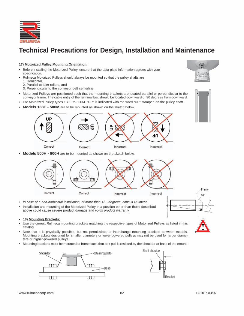
www.rulmecacorp.com TC101: 03/0782
17) Motorized Pulley Mounting Orientation:• Before installing the Motorized Pulley, ensure that the data plate information agrees with your
specification.• Rulmeca Motorized Pulleys should always be mounted so that the pulley shafts are
1. Horizontal, 2. Parallel to idler rollers, and 3. Perpendicular to the conveyor belt centerline.
• Motorized Pulleys are positioned such that the mounting brackets are located parallel or perpendicular to theconveyor frame. The cable entry of the terminal box should be located downward or 90 degrees from downward.
• For Motorized Pulley types 138E to 500M “UP” is indicated with the word “UP” stamped on the pulley shaft. • Models 138E - 500M are to be mounted as shown on the sketch below.
• Models 500H - 800H are to be mounted as shown on the sketch below.
• In case of a non-horizontal installation, of more than +/-5 degrees, consult Rulmeca. • Installation and mounting of the Motorized Pulley in a position other than those described
above could cause severe product damage and voids product warranty.
• 18) Mounting Brackets:• Use the correct Rulmeca mounting brackets matching the respective types of Motorized Pulleys as listed in this
catalog.• Note that it is physically possible, but not permissible, to interchange mounting brackets between models.
Mounting brackets designed for smaller diameters or lower-powered pulleys may not be used for larger diame-ters or higher-powered pulleys.
• Mounting brackets must be mounted to frame such that belt pull is resisted by the shoulder or base of the mount-
Technical Precautions for Design, Installation and Maintenance
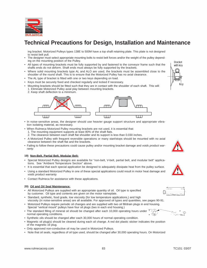
www.rulmecacorp.com TC101: 03/0783
ing bracket. Motorized Pulleys types 138E to 500M have a top shaft retaining plate. This plate is not designedto resist belt pull.
• The designer must select appropriate mounting bolts to resist belt forces and/or the weight of the pulley depend-ing on the mounting position of the Pulley.
• All types of mounting brackets must be fully supported by and fastened to the conveyor frame such that theshafts ends do not deform. Shaft ends must always be fully supported by the brackets.
• Where solid mounting brackets type AL and ALO are used, the brackets must be assembled close to theshoulder of the round shaft. This is to ensure that the Motorized Pulley has no axial clearance.
• The AL type of bracket is fitted with one or two keys depending on load.• Keys must be securely fixed and checked regularly and locked if necessary.• Mounting brackets should be fitted such that they are in contact with the shoulder of each shaft. This will:
1. Eliminate Motorized Pulley axial play between mounting brackets.2. Keep shaft deflection to a minimum.
• In noise-sensitive areas, the designer should use heavier gauge support structure and appropriate vibra-tion isolating material, as necessary.
• When Rulmeca Motorized Pulley mounting brackets are not used, it is essential that: 1. The mounting equipment supports at least 80% of the shaft flats. 2. The clearance between each shaft flat shoulder and its support is less than 0.030 inches.
• A Motorized Pulley with frequent reversible operations or many start/stops should be mounted with no axialclearance between the shaft flat and the brackets.
• Failing to follow these precautions could cause pulley and/or mounting bracket damage and voids product war-ranty.
19) Non-Belt, Partial Belt, Modular Belt:• Special Motorized Pulley designs are available for “non-belt, V-belt, partial belt, and modular belt” applica-
tions. See “Ambient Temperature Section” above.• It is essential that each special application be designed to adequately dissipate heat from the pulley surface.• Using a standard Motorized Pulley in one of these special applications could result in motor heat damage and
voids product warranty.• Contact Rulmeca for assistance with these applications.
20) Oil and Oil Seal Maintenance:• All Motorized Pulleys are supplied with an appropriate quantity of oil. Oil type is specified
by customer. Oil type and contents are given on the motor nameplate.• Standard, synthetic, food grade, low viscosity (for low temperature applications,) and high
viscosity (in noise-sensitive areas) are all available. For approved oil types and quantities, see pages 90-91.• Motorized Pulleys require periodic oil changes and are supplied with two oil fill/drain plugs in end housing.
Special “vertical mount” pulleys have four oil plugs (two in each end housing.)• The standard filling of mineral oil should be changed after each 10,000 operating hours under
normal operating conditions. • Synthetic oils should be changed after each 30,000 hours of normal operating condition. • Magnetic oil plug(s) should be cleaned during each oil change. A red dot plastic sticker indicates the position
of the magnetic oil plug.• Only approved non-conductive oil may be used in Motorized Pulleys.• Note that oil seals, regardless of oil type used, should be changed after 30,000 operating hours. On Motorized
Technical Precautions for Design, Installation and Maintenance

www.rulmecacorp.com TC101: 03/0784
Pulley types 320M to 800H oil seals may be changed without removing Motorized Pulley from conveyor. Motor-ized Pulley standard types 138E to TM320L require Pulley disassembly to change oil seals. Rulmeca servicepersonal or authorized local service providers to perform this work.
• Take special precautions when changing brands of oil and types of oil because of potential oil incompatibility.Contact your local oil supplier for assistance. For example, when changing from standard to synthetic oil, it is necessary to: 1. Completely drain old standard oil;2. Partially fill pulley with “Clean-Flush-Lubricate” (CFL) fluid;3. Run pulley for 20 minutes; 4. Drain CFL fluid completely; then 5. Fill pulley with appropriate amount of new synthetic oil.
• Failing to observe these oil and oil seal precautions could shorten pulley service life and voids product warranty.• All the above instructions refer to Motorized Pulleys constantly working under full load. In case of Motorized
Pulleys not working continuously under full load, the service life will increase considerably. When checking theoil, the cleanness of the oil is always the best guideline of– The wear and condition of the gears and bearings– Whether to change the oil immediately or possibly delay the oil change
21) Pulley Diameter:• The type and size of conveyor belt will determine the minimum allowable Motorized Pulley diameter. Using a
pulley diameter too small for the belt can cause belt de-lamination, belt splice damage and can shorten bothbelt and pulley lagging life. Contact your belting supplier before specifying a pulley diameter.
22) Regreasable Labyrinth Seals:• All Rulmeca Motorized Pulleys are hermetically sealed. Standard oil seals are designed to contain oil within the
Motorized Pulley during normal operating conditions. They are capable of withstanding an internal pressure risethat occurs as the pulley motor temperature increases.
• Optional regreasable labyrinth seals are available to protect oil seals from harsh operating or maintenanceconditions. Each labyrinth seal provides a barrier of steel and grease to prevent ingress of dust and fluid throughthe oil seal.
• In abrasive operating conditions labyrinth seals should be periodically grease-purged to flush abrasive dustaway from the oil seal.
• In wet conditions, where it is common to wash down equipment with high-pressure detergent spray, labyrinthseals should be refilled with grease after each wash-down. High-pressure sprays remove grease from thelabyrinth seal, removing an important part of the barrier to fluid ingress.
• Grease should always be seen at the labyrinth gap.• If in some circumstances the re-grease frequency is high, an automatic greasing system is recommended.• Failing to perform necessary labyrinth seal maintenance could shorten service life and voids product warranty.
23) Repair and Mechanical Maintenance:• Normally Motorized Pulleys require no specific attention during their operation other than the changing of oil
and oil seals. They are ready for operation immediately after connection to the power supply.• If repair or maintenance is required, the Motorized Pulley must be disconnected from the power supply before
the terminal box may be opened.• During a test run, the shaft ends must be correctly fixed to the support frame and suitable guarding must be pro-
vided around rotating parts to protect personnel.
24) Reversing Conveyors:• All Motorized Pulleys for a three-phase power supply are reversible. Mechanical backstop option is not possi-
ble for reversible conveyor applications.• The conveyor drive control system must be designed to bring the Motorized Pulley to a complete stop before
reversing conveyor belt direction.
Technical Precautions for Design, Installation and Maintenance

www.rulmecacorp.com TC101: 03/0785
• Reversing conveyor direction without stopping the drive motor will damage motor and gearbox and voids prod-uct warranty.
25) Surface Coating:• Motorized Pulley models 400L to 800H are supplied with a standard salt water resistant primary paint coat of
2.4 mil. For aggressive environmental conditions the Motorized Pulley should also be painted to a thicknessof 4.7 mil.
• In this case it is essential that no paint enter the gap between the shaft and the end housing to prevent shaftsealing damage.
• Motorized Pulley types 138E to 320H are supplied with powder coated end housings. The shells and shafts aretreated with anti-rust wax.
26) Storage of Motorized Pulleys:• During storage Rulmeca Motorized Pulleys must be:
– stored in a building or, as a minimum, covered by an awning.– protected against direct sunlight to insure that sealing system does not dry out.– rotated at least 180 degrees every 6 months to lubricate all internal components.
• If Motorized Pulleys must be stored longer than 1 year, they must be tested before being put into operation.Such a test should include the following.– Motor winging should be checked with an insulation tester.– Winding resistance should be checked.– Thermal protector should be checked with a continuity tester.– Pulley should be connected to the power supply and run for a minimum of 30 minutes– Pulley should then be checked to verify that there are no oil leaks – Pulley should then be checked to verify that pulley body temperature does not exceed 160° F.
• For safety reasons check that the Motorized Pulley is properly fixed to the test frame during the test.
27) Start-up:• Prior to initial start-up of Motorized Pulley:
– Verify that Motorized Pulley nameplate data matches customer specification.– Ensure electrical connections are correct.– Check that Motorized Pulley is free to rotate.– Check that slack side belt tension is adequate to prevent belt slippage.– Check that belt is not over-tensioned.– Ensure that oil is present in the Motorized Pulley.
28) Terminal Box:• Rulmeca Motorized Pulleys are available with terminal boxes or power cords to facilitate electrical installation.
Power cords are available up to a motor power of 5.5 HP.• Two types of terminal box are available:
1. Standard large terminal box with threaded brass terminals.2. Optional compact terminal box with clamp terminals (WAGO) up to a motor power of 5.5 HP.
• Switch off Motorized Pulley power supply and control circuit(s) before opening terminal box.• Each terminal box has one or more conduit nipples and a cover plate. The cover plate should be removed to
facilitate termination of power and control wires within the terminal box. After wire connections are made coverplate should be replaced.
• Terminal boxes should never be disassembled or removed from the end of the shaft to reorient conduit nipplelocation.
• Modifications to terminal boxes should only be made by an authorized Rulmeca service center or after obtain-ing permission and instructions, in writing, from Rulmeca.
• A wiring diagram is placed inside the terminal box on the back of the terminal box cover.• Dismantling and reassembling a terminal box could cause a short circuit in the factory set (and tested) inter-
nal wiring and voids product warranty.
Technical Precautions for Design, Installation and Maintenance

www.rulmecacorp.com TC101: 03/0786
29) Transport and Handling:• For safety reasons during transport and assembly a lifting rope suitable to support the weight of the pulley must
be used. The weight of the pulley is stamped on the data plate and /or given in the catalog. • The rope must be fixed on the shaft ends.• For Motorized Pulley types 500H – 800H, a steel rope or chains should be fixed to the eyebolts,
which are located on the mounting brackets.
30) Variable Frequency Drive:• It is essential that each Variable Frequency Drive (VFD) be set within the motor’s allowable operating spec-
trum. For Rulmeca Motorized Pulleys the allowable frequency spectrum is 12 Hz to 66 Hz. There will be nomore than 5% torque loss within this range. This means that a Rulmeca Motorized Pulley is essentially a “con-stant torque” conveyor belt drive within the allowable frequency range.
• If operators attempt to drive the motor outside of the allowable range, then torque loss becomes significant,motor current draw elevates, motor cooling can become problematic, and product warranty is void.
• Do not allow resonant frequencies in the power line to cause voltage spikes in the motor. It is possible forthe VFD to set up resonant frequencies in the power line between the VFD and the motor if the power line istoo long. Potential resonant frequencies may be eliminated in two ways. Either limit the distance between theVFD and the motor (some VFD manufacturers recommend cable lengths of 30 feet or less) or simply installa filter on the VFD output (available from VFD manufacturer.)
• To avoid any radio interference the cable from motor to the VFD may be screened and properly grounded.• The power and current range of the VFD must be selected according to the full load amperage given on the
Motorized Pulley data plate.• Do not undersize the conveyor drive. Make certain the conveyor drive provides enough belt pull at each end
of the desired belt speed range. Remember that horsepower is linearly proportional to frequency.• For example, a 10 HP Motorized Pulley, which is designed to provide 1,080 lbs of belt pull at a conveyor
speed of 300 feet per minute (fpm) on a three phase power supply of 460 volts and 60 Hz, will provide approx-imately 1,080 lbs of belt pull at 60 Hz. By definition, 1 HP equals 33,000 foot-lbs per minute. Therefore, this10 HP unit provides 1,080 lbs x 300 fpm = 324,000 ft-lbs/minute of power. This equates to (324,000 ft-lbs/minute)/(33,000 ft-lbs/minute/HP) = 9.8 HP.
• If the Motorized Pulley described above is run at 30 Hz to provide a belt speed of 150 fpm, the torque (or “beltpull”) stays constant and the belt speed decreases. Therefore, the 10 HP unit described above, while run-ning at 30 Hz, will provide the following power. 1,080 lbs x 150 fpm = 162,000 ft-lbs/minute. Note that powerat this frequency only equals (162,000 ft-lbs/minute)/(33,000 ft-lbs/minute/HP) = 4.9 HP.
• If design conditions require 10 HP at 300 fpm an 10 HP at 150 fpm, the designer will undersize the drive if hespecifies a 10 HP Motorized Pulley to be driven by a VFD at 60 Hz and 30 Hz. This is because the Motor-ized Pulley will only provide 4.9 HP at 150 fpm (30 Hz), as shown above. Therefore, if the designer knowshe will need 10 HP at 300 fpm and 10 HP at 150 fpm, he should specify a 20 HP unit designed to provide a300 fpm belt speed at 60 Hz. In this way when he uses a VFD to slow down the drive, he will have 10 HPavailable at 150 fpm (30 Hz0 and more than 10 HP available at 300 fpm (60 Hz.)
• Contact VFD supplier to properly match the VFD capabilities with the conveyor Operating requirements andMotorized Pulley electrical characteristics.
Technical Precautions for Design, Installation and Maintenance

www.rulmecacorp.com TC101: 03/07
Taconite Plant Control Panel- “Before & After” (Minnesota—USA)Left photo shows control panel of taconite plant DC-powered variable speedconveyor control system before 1995 conversion to AC drives. Note SCR's,relay banks, and timer banks.
Right side shows control panel after conversion to AC motorized pulleyscontrolled with variable frequency drives. Elimination of SCR's and relaybanks improved reliability, simplified troubleshooting, and reduced energyloss.
Technical Precaution: The power and current range of the VFD must beselected according to the full load amperage given on the Motorized Pulleydata plate.
87
Motorized PulleysVariable Frequency Drives
Taconite Plant - After Conversion (Minnesota—USA)Taconite processor converted limestone feeder conveyor drives from 1975vintage DC motors and chain/sprocket speed reducers to 460 volt 3 phase60 Hz AC-powered Motorized Pulleys in 1995. Photo was taken beforechute and hood were reinstalled. ABB variable frequency drive (VFD) driveseach 19.72” diameter 5.5 HP motorized pulley to a maximum belt speed of120 FPM. Torque loss is limited to less than 5% because operating fre-quencies are between 12 and 66 Hz.
Technical Precaution: When driving motorized pulley with VFD on 460 volt3 phase 60 Hz power supply, always restrict frequencies to allowable fre-quency spectrum of 12 to 66 Hz to avoid torque loss and heat build-up.
Various Limestone Quarries (Georgia—USA)Photo shows two of ten 15.75” diameter Motorized Pulleys installed 1994-1998 to automatically “choke feed” tertiary gyratory crushers. Working incombination with a VFD and an ultrasonic sensor, each Motorized Pulleydrives a 36” wide belt at a maximum speed of 120 FPM to transfer 4” minusproduct from hopper to crusher throat at 425 TPH.
Technical Precaution: When driving motorized pulley with VFD, filter VFDoutput if it is more than 30’ from motorized pulley to avoid resonance-induced voltage spikes.
Taconite Plant - Before Conversion (Minnesota—USA)Prior to 1995 conversion to Motorized Pulleys, old maintenance-prone chain& sprocket units served as DC motor speed reducers. Frequent lubricationof pulley pillow blocks, maintenance of chains/sprockets, expanded metalsafety guards, and DC motors were all eliminated with the installation ofMotorized Pulleys at this location.
Technical Precaution: When converting a system to use a VFD do notundersize the conveyor drive. Make certain conveyor drive provides enoughbelt pull at each end of the desired belt speed range. Remember that horse-power is linearly proportional to frequency (e.g. a 10 HP Motorized Pulley,designed to provide 1,080 lbs of belt pull at 460 volts and 60 Hz, will provideapproximately 1,080 lbs of belt pull at 30 Hz, but this equates to 4.9 HP.)

www.rulmecacorp.com TC101: 03/0788
Protection against solid bodies
IP Symbol Test Definition
Not Protected
Protected against touch with theflat of the hand and large solidobjects greater than 50mm
Protected against finger-touch andsolid objects greater than 12mm.
Protected against solid objectsgreater than 2.5mm
Protected against solid objectsgreater than 1.0mm.
Dust-protected!Dust shall not penetrate in a quan-tity to interfere with the satisfac-tory operation of the apparatus.
Dust-tight
0
1
2
3
4
5
6
31) International Protection (IP) Ratings
Protection of internal equipment against harmful ingress of water
IP Symbol Test Definition
Not Protected!
Protected against dripping water.
Protected against dripping waterwhen tilted up 15°.
Protected against spraying water.
Protected against splashing water.
Protected against water jets (P1 nozzle 6.3mm, water delivery rate12.5 l/min ± 5%)
Protected from projections of watersimilar to marine swells (P2 nozzle 12.5mm, water deliveryrate 100 l/min ± 5%)
Ingress of water in quantities causing harmful effects shall not be possible when the enclosure is temporarily (30 min.) immersed 1 meter in water under standardizedconditions of pressure and time
Ingress of water in quantities causingharmful effects shall not be possiblewhen the enclosure is continuouslyimmersed in water under conditions,which shall be agreed between manufacturer and the user, but aremore severe than for no. 7
0
1
2
3
4
5
6
7
8
Technical Precautions for Design, Installation and Maintenance

www.rulmecacorp.com TC101: 03/07
Ceramic - Segments and BlocksTwo types of ceramic lagging are available: Solid Red Porous Ceramic Seg-ments (see photo on left) bonded directly to steel pulley face and SolidGreen Porous Ceramic Blocks (see photo insert) hot vulcanized into blacksynthetic rubber. Both types are available in “full” and “partial” face widthconfigurations are offer high traction and excellent resistance to wear.
89
“Full” Diamond Pattern Synthetic RubberMost popular lagging is 1/4” thick cold-bonded black diamond pattern syn-thetic rubber lagging in 60 durometer +/- 5 (shore hardness A.) This long-lasting material has excellent frictional characteristics in wet or dry, outdoorand indoor applications for single direction and reversing belts. Asdescribed on pages 80 & 81, other thicknesses are available as well assmooth, white, and oil-resistant rubber. Hot vulcanized bonding is alsoavailable.
Technical Precaution: Lagging thickness effects pulley heat dissipationcharacteristics. Refer to “Lagging Limitations” chart on page 80.
“Partial” Smooth Pattern Synthetic RubberAs described above, certain power and belt speed combinations require thatlagging be restricted to the outer thirds of the pulley face to improve heat dis-sipation. Photo on left shows partial lagging at 3/8” thick hot vulcanizedblack smooth pattern synthetic rubber lagging in 60 durometer +/- 5 (shorehardness A.)
Also note standard painted type ALOE mounting bracket, complete with lift-ing lug.
“Partial” Diamond Pattern Synthetic RubberCertain power and belt speed combinations require that lagging be restrict-ed to the outer thirds of the pulley face to improve heat dissipation. Each“partially lagged” pulley has an extra thick pulley shell in the center of thepulley face. Most popular partial lagging is 3/8” thick cold-bonded black dia-mond pattern synthetic rubber lagging in 60 durometer +/- 5 (shore hard-ness A.) As described on pages 80 & 81, other thicknesses are availableas well as smooth, white, and oil-resistant rubber. Hot vulcanized bondingis also available.
Also note optional regreasable stainless steel bearing cover and nicole plat-ed type AL mounting bracket, complete with lifting lug, grease nipple, andgib key.
Motorized PulleysLagging Options
Most popular ceramic lagging is 0.59” thick.
Technical Precaution: Lagging thickness effects pulleyheat dissipation characteristics. Refer to “Lagging Limi-tations” chart on page 80.
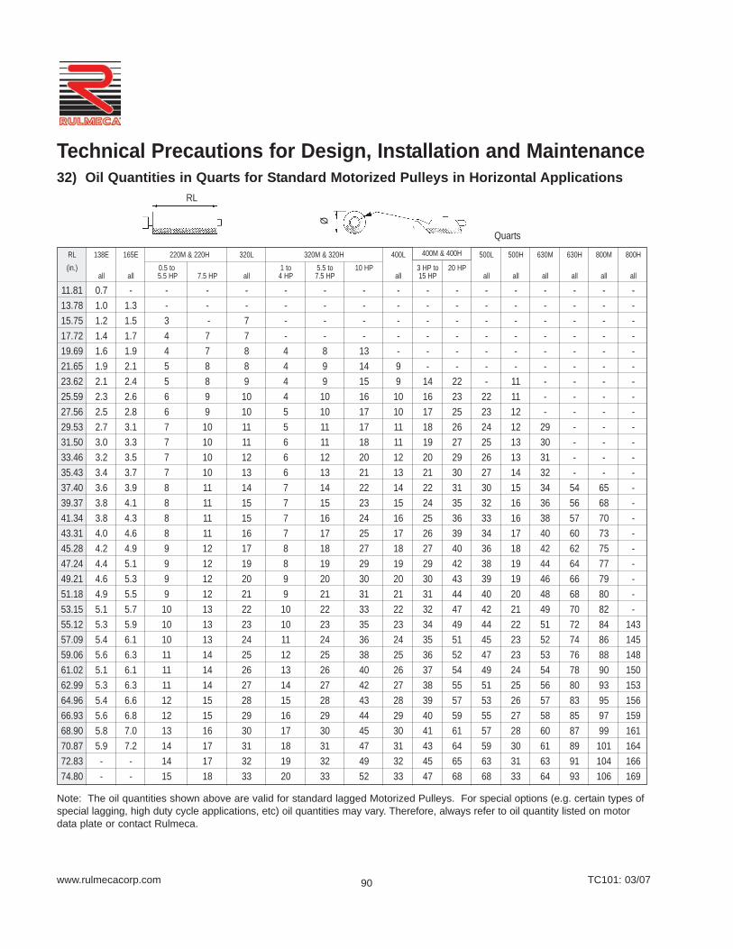
www.rulmecacorp.com TC101: 03/07
RL 138E 165E 220M & 220H 320L 320M & 320H 400L 400M 400H 500L 500H 630M 630H 800M 800H(in.) 0.5 to 1 to 5.5 to 10 HP 3 HP to 20 HP
all all 5.5 HP 7.5 HP all 4 HP 7.5 HP all 15 HP all all all all all all
11.81 0.7 - - - - - - - - - - - - - - - -13.78 1.0 1.3 - - - - - - - - - - - - - - -15.75 1.2 1.5 3 - 7 - - - - - - - - - - - -17.72 1.4 1.7 4 7 7 - - - - - - - - - - - -19.69 1.6 1.9 4 7 8 4 8 13 - - - - - - - - -21.65 1.9 2.1 5 8 8 4 9 14 9 - - - - - - - -23.62 2.1 2.4 5 8 9 4 9 15 9 14 22 - 11 - - - -25.59 2.3 2.6 6 9 10 4 10 16 10 16 23 22 11 - - - -27.56 2.5 2.8 6 9 10 5 10 17 10 17 25 23 12 - - - -29.53 2.7 3.1 7 10 11 5 11 17 11 18 26 24 12 29 - - -31.50 3.0 3.3 7 10 11 6 11 18 11 19 27 25 13 30 - - -33.46 3.2 3.5 7 10 12 6 12 20 12 20 29 26 13 31 - - -35.43 3.4 3.7 7 10 13 6 13 21 13 21 30 27 14 32 - - -37.40 3.6 3.9 8 11 14 7 14 22 14 22 31 30 15 34 54 65 -39.37 3.8 4.1 8 11 15 7 15 23 15 24 35 32 16 36 56 68 -41.34 3.8 4.3 8 11 15 7 16 24 16 25 36 33 16 38 57 70 -43.31 4.0 4.6 8 11 16 7 17 25 17 26 39 34 17 40 60 73 -45.28 4.2 4.9 9 12 17 8 18 27 18 27 40 36 18 42 62 75 -47.24 4.4 5.1 9 12 19 8 19 29 19 29 42 38 19 44 64 77 -49.21 4.6 5.3 9 12 20 9 20 30 20 30 43 39 19 46 66 79 -51.18 4.9 5.5 9 12 21 9 21 31 21 31 44 40 20 48 68 80 -53.15 5.1 5.7 10 13 22 10 22 33 22 32 47 42 21 49 70 82 -55.12 5.3 5.9 10 13 23 10 23 35 23 34 49 44 22 51 72 84 14357.09 5.4 6.1 10 13 24 11 24 36 24 35 51 45 23 52 74 86 14559.06 5.6 6.3 11 14 25 12 25 38 25 36 52 47 23 53 76 88 14861.02 5.1 6.1 11 14 26 13 26 40 26 37 54 49 24 54 78 90 15062.99 5.3 6.3 11 14 27 14 27 42 27 38 55 51 25 56 80 93 15364.96 5.4 6.6 12 15 28 15 28 43 28 39 57 53 26 57 83 95 15666.93 5.6 6.8 12 15 29 16 29 44 29 40 59 55 27 58 85 97 15968.90 5.8 7.0 13 16 30 17 30 45 30 41 61 57 28 60 87 99 16170.87 5.9 7.2 14 17 31 18 31 47 31 43 64 59 30 61 89 101 16472.83 - - 14 17 32 19 32 49 32 45 65 63 31 63 91 104 16674.80 - - 15 18 33 20 33 52 33 47 68 68 33 64 93 106 169
90
32) Oil Quantities in Quarts for Standard Motorized Pulleys in Horizontal Applications
Note: The oil quantities shown above are valid for standard lagged Motorized Pulleys. For special options (e.g. certain types ofspecial lagging, high duty cycle applications, etc) oil quantities may vary. Therefore, always refer to oil quantity listed on motordata plate or contact Rulmeca.
Quarts
RL
Ø
Technical Precautions for Design, Installation and Maintenance
400M & 400H

www.rulmecacorp.com TC101: 03/07
Motorized Pulley Motor Allowable ISO 3498 DIN 51517-3 Castrol BP ESSO Mobiloil Shell TexacoModel and Insulation Ambient Viscosity Performance
Type of Oil Class Temperature1 Grade4 Requirements
Ø138-800 -13°F to ALPHA ENERGOL SPARTAN MOBILGEAR OMALA MEROPAStandard Oil F +104°F 150 CLP SP 150 GR-XP 150 EP 150 629 150 150
Ø138-800 -13°F to ALPHA- - SPARTAN SHC 630 - -Synthetic Oil2 F +104°F 220 CLP SYNTH 220 Syn. EP 220
Ø138-800 -13°F to ALPHA- - SPARTAN SHC 630 - -Synthetic Oil2 H +120°F 220 CLP SYNTH 220 Syn. EP 220
Ø138-800 -22°F to - - - - - Shell Cassida -Food Grade Oil3 F & H +104°F 220 GL220
Model Inclination Typical PrecautionsAngle (α) application
138E & 165E 5° to 90° Magnetic220M & 220H Separators320L, 320M & 320H400L
Special design & special oilquantity. Contact Rulmecabefore placing order.
91
32) Oil Quantities in Quarts for Motorized Pulleys in Vertical Applications
32) Oil Quantities for Special Version Motorized Pulleys - Contact Rulmeca
quarts
33) Oil Specifications
Model Oil Quantity SpecificationsQuarts
138E 1.5165E 3.2220M 10.6220H 10.6320L 26.4320M 26.4320H 26.4400L 42.3
Electricalconnection
to belocated
at the top
Note:The oil quantities shown are validfor standard vertical Motorized Pul-leys. For special options (e.g. cer-tain types of lagging, high dutycycle applications, etc) oil quanti-ties may vary. Therefore, alwaysrefer to oil quantity listed on motordata plate.
1 Allowable ambient temperature refers to temperature in the vicinity of Motorized Pulley. See Technical Precautions page 77-78.2 Synthetic oil is supplied with all Class H motors. It is also available with Class F motors to reduce oil change frequency (see page 83,) reduce gear wear, and
reduce noise.3 This oil complies with food additive regulation 12 CPR.4 ISO Viscosity Grades are shown in centistokes at +104°F. See also ISO 3498 and DIN 31519 for more information.
Technical Precautions for Design, Installation and Maintenance

www.rulmecacorp.com TC101: 03/07
Technical Precautions for Design, Installation and Maintenance
USA standard 460V power supply
USA standard 230V power supply
34) External ConnectionDiagrams for StandardMotorized Pulleys
Standard Terminal Box0.5 HP - 180 HP
92
Diagrams are valid for MotorizedPulleys manufactured after Janu-ary 2004. For units built prior tothis date contact Rulmeca or referto Repair and Maintenance Guideavailable atwww.rulmecacorp.com.
T1 & T2 = Internal bi-metallic ther-mal protection switch which MUSTBE CONNECTED to external nor-mally closed control circuit.
See Technical Precautions pages76 - 86 for complete electricaldesign, installation, and mainte-nance instructions.
115V1PH
60 Hznormally closedcontrol circuit
115V1PH
60 Hznormally closedcontrol circuit
fuse(breaker)
fuse(breaker)
3 pole starter(contactor)
3 pole starter(contactor)
fuses (breaker)
fuses (breaker)
460V3PH
60 Hzpower supply
230V3PH
60 Hzpower supply
L3
L2
L1
L3
L2
L1
U2
V2
V1
W2
W1U1
T2T1
U2W2
V2
V1
U1 W1
T1 T2

www.rulmecacorp.com TC101: 03/07
Technical Precautions for Design, Installation and Maintenance
34) External ConnectionDiagrams for StandardMotorized Pulleyswith Internal Brake
Standard Terminal Box0.5 HP - 180 HP
USA standard 460V power supply(with 207VDC brake)
USA standard 230V power supply(with 104VDC brake)
93
Diagrams are valid for MotorizedPulleys manufactured after January2004. For units built prior to thisdate contact Rulmeca or refer toRepair and Maintenance Guideavailable at www.rulmecacorp.com.
T1 & T2 = Internal bi-metallic ther-mal protection switch which MUSTBE CONNECTED to external nor-mally closed control circuit.
See Technical Precautions pages76 - 86 for complete electricaldesign, installation, and mainte-nance instructions.
Brake rectifier is shown with jumperacross terminals 3 and 4. Thisenables AC power supply to rectifi-er to stop and start brake. Brakeresponsiveness may be improvedby connecting an external switch toterminals 3 and 4.
Internal electromagnetic brake isavailable in models 220M - 500M.
115V1PH
60 Hznormally closedcontrol circuit
115V1PH
60 Hznormally closedcontrol circuit
460V3PH
60 Hzpower supply
230V3PH
60 Hzpower supply
3 pole starter(contactor)
3 pole starter(contactor)
fuse(breaker)
fuse(breaker)
fuses (breaker)
fuses (breaker)
brake rectifierterminations
brake rectifierterminations
460V60 Hz
230V60 Hz
W2
W2
U2
U2
V2
V2
U1
U1
V1
V1
W1
W1
1 542 63
1 2 3 4 5 6
T1
T1
T2
T2
F2F1
F2F1
L3
L2
L1
L3
L2L1

www.rulmecacorp.com TC101: 03/07
Technical Precautions for Design, Installation and Maintenance
94
Non-USA standard power supply (High Voltage)
Non-USA standard power supply (Low Voltage)
T1 & T2 = Internal bi-metallic ther-mal protection switch which MUSTBE CONNECTED to external nor-mally closed control circuit.
See Technical Precautions pages76 - 86 for complete electricaldesign, installation, and mainte-nance instructions.
VAC1PH
normally closedcontrol circuit
VAC1PH
normally closedcontrol circuit
VAC3PH
power supply
VAC3PH
power supply
3 pole starter(contactor)
3 pole starter(contactor)
fuse(breaker)
fuse(breaker)
fuses (breaker)
fuses (breaker)
W2
W2
U2
U2
V2
V2
U1
U1
V1
V1
W1
W1
T1
T1
T2
T2
L3L2
L1
L3
L2
L1
34) External ConnectionDiagrams for StandardMotorized Pulleys
Standard Terminal Box0.5 HP - 180 HP

www.rulmecacorp.com TC101: 03/07
Technical Precautions for Design, Installation and Maintenance
95
Non- USA standard power supply (High Voltage)
Non- USA standard power supply (Low Voltage)
T1 & T2 = Internal bi-metallic ther-mal protection switch which MUSTBE CONNECTED to external nor-mally closed control circuit.
See Technical Precautions pages76 - 86 for complete electricaldesign, installation, and mainte-nance instructions.
Brake rectifier is shown with jumperacross terminals 3 and 4. Thisenables AC power supply to rectifi-er to stop and start brake. Brakeresponsiveness may be improvedby connecting an external switch toterminals 3 and 4.
Internal electromagnetic brake isavailable in models 220M - 500M.
VAC1PH
normally closedcontrol circuit
VAC1PH
normally closedcontrol circuit
VAC3PH
power supply
VAC3PH
power supply
3 pole starter(contactor)
3 pole starter(contactor)
fuse(breaker)
fuse(breaker)
fuses (breaker)
fuses (breaker)
brake rectifierterminations
brake rectifierterminations
VAC1PH
VAC1PH
W2
W2
U2
U2
V2
V2
U1
U1
V1
V1
W1
W1
1 2 4 53 6
1 2 3 4 5 6
T1
T1 T2
T2
F2F1
F2F1
L3
L2L1
L3
L2L1
34) External ConnectionDiagrams for StandardMotorized Pulleyswith Internal Brake
Standard Terminal Box0.5 HP - 180 HP
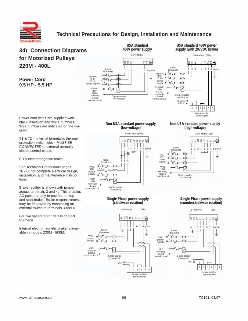
www.rulmecacorp.com TC101: 03/07
Technical Precautions for Design, Installation and Maintenance
96
USA standard 460V power supply
USA standard 460V powersupply (with 207VDC brake)
Non-USA standard power supply(low voltage)
Non-USA standard power supply(high voltage)
Single Phase power supply (counterclockwise rotation)
Single Phase power supply (clockwise rotation)
Power cord wires are supplied withblack insulation and white numbers.Wire numbers are indicated on the dia-gram.
T1 & T2 = Internal bi-metallic thermalprotection switch which MUST BECONNECTED to external normallyclosed control circuit.
EB = electromagnetic brake
See Technical Precautions pages 76 - 86 for complete electrical design,installation, and maintenance instruc-tions.
Brake rectifier is shown with jumperacross terminals 3 and 4. This enablesAC power supply to rectifier to stopand start brake. Brake responsivenessmay be improved by connecting anexternal switch to terminals 3 and 4.
For two speed motor details contactRulmeca.
Internal electromagnetic brake is avail-able in models 220M - 500M.
2 pole starter(contactor)
2 pole starter(contactor)
3 pole starter(contactor)
3 pole starter(contactor)
3 pole starter(contactor)
3 pole starter(contactor)
fuses (breaker)
fuses (breaker)
fuses (breaker)
fuses (breaker)
fuses (breaker)
fuses (breaker)
460VAC3PH
60 Hzpower supply
460VAC3PH
60 Hzpower supply
115VAC1PH
60 Hznormallyclosed
control circuit
115VAC1PH
60 Hznormallyclosed
control circuit
VAC1PH
normallyclosed
control circuitVAC1PH
normallyclosed
control circuit
VACnormallyclosed
control circuit
VACnormallyclosed
control circuit
3-Ph-Motor 3-Ph-Motor (EB)
460VAC60 Hz
brake rectifierterminations
brake rectifierterminations
brake rectifierterminations
VAC3PH
power supply
VAC3PH
power supply
3-Ph-Motor (Delta) 3-Ph-Motor (Star)
1-Ph-Motor (EB) 1-Ph-Motor (EB)
VACpower supply
VACpower supply
VACVAC
U1
V1
W1
W2
U2
V2
T1 T2 U1
V1
W1
W2
U2
V2
T1 T2
U1
V1
W1
T1 T2 U1
V1
W1
T1 T2 F1 F2
Z1 U1
U2
Z2 B1
B2
T1 T2 Z2 U1
U2
Z1 B1
B2
T1 T2
L1
L2
L3 L3
L2
L1
L1
L1
L1 L1N N
L2
L2
L3
L3
1 2 3 4 5 gn/ye 1 2 3 4 5 6 7 gn/ye
1 2 3 4 5 6 7 8 gn/ye
1 2 3
1 2 3 4 5 6 7 8 gn/ye
3 1 2 4 5 6 7 8 gn/ye 4 1 2 3 5 6 7 8 gn/ye
1 2 3 4 5 6
1 2 3 4 5 61 2 3 4 5 6
34) Connection Diagramsfor Motorized Pulleys 220M - 400L
Power Cord0.5 HP - 5.5 HP

34) Connection Diagramsfor Motorized Pulleys138E - 400L
Compact Terminal Boxand WAGO-Clamp0.13 HP - 5.5 HP
www.rulmecacorp.com TC101: 03/07
Technical Precautions for Design, Installation and Maintenance
T1 & T2 = Internal bi-metallic thermalprotection switch which MUST BECONNECTED to external normallyclosed control circuit.
See Technical Precautions pages 76 -86 for complete electrical design,installation, and maintenance instruc-tions.
Characters in parentheses are for 2 stage gearbox
Brake rectifier is shown with jumperacross terminals 3 and 4. Thisenables AC power supply to rectifierto stop and start brake. Brakeresponsiveness may be improved byconnecting an external switch to ter-minals 3 and 4.
For two speed motor details contactRulmeca.
RD = RedYE = YellowBK = BlackGY = GreyBU = BlueGN = GreenWH = WhiteBN = BrownT1 & T2 = Thermal ProtectorEB = Electromagnetic brake
97
Assembly instructions
USA standard 460V power supply
Non-USA standard power supply
USA standard 230V power supply
3 pole starter(contactor)
3 pole starter(contactor)
3 pole starter(contactor)
3 pole starter(contactor)
3 pole starter(contactor)
3 pole starter(contactor)
fuses (breaker)
fuses (breaker)
fuses (breaker)
fuses (breaker)
fuses (breaker)
fuses (breaker)
brake rectifier terminations
brake rectifier terminations
brake rectifier terminations
460VAC3PH
60 Hzpower supply
460VAC3PH
60 Hzpower supply
VAC1PH
normallyclosed
control circuit
VAC1PH
normallyclosed
control circuit
460VAC60 Hz
230VAC60 Hz
115VAC1PH
60 Hznormally closed
control circuit
115VAC1PH
60 Hznormally closed
control circuit
207VDCelectro-magneticbrake
104VDCelectro-magneticbrake
3-Ph-Motor3-Ph-Motor
3-Ph-Motor3-Ph-Motor
3-Ph-Motor (Delta)3-Ph-Motor (Delta)
115VAC1PH
60 Hznormally closed
control circuit
115VAC1PH
60 Hznormally closed
control circuit
230VAC3PH
60 Hzpower supply
230VAC3PH
60 Hzpower supply
VDCelectro-magneticbrake
VAC
VAC3PH
powersupply
VAC3PH
powersupply
(1.) Pushdownclamp
(2.) Push inwire
L1 L1
L1 L1
L1 L1
L2 L2
L2 L2
L2 L2
L3 L3
L3 L3
L3 L3
TC/THS TC/THS
TC/THS TC/THS
TC/THS TC/THS
EB
EB
EB
1 2 3 4 5 6
1 2 3 4 5 6
1 2 3 4 5 6
(ye) (rd)rd ye bu gn gn bu gn gn wh wh
(ye) (rd)rd ye
(ye) (rd)rd ye
(ye) (rd)rd yebu gn gn bu gn gn wh wh
bu bu gn gn bu bu gn gn wh wh(ye)(gy)(rd)(bk)
rd bk ye gy (ye)(gy)(rd)(bk)
rd bk ye gy
Y L1 L2 L3 T1 T2 B1 B2 Y L1 L2 L3 T1 T2 B1 B2
Y L1 L2 L3 T1 T2 B1 B2Y L1 L2 L3 T1 T2 B1 B2
Y L1 L2 L3 T1 T2 B1 B2 Y L1 L2 L3 T1 T2 B1 B2

www.rulmecacorp.com TC101: 03/07
Technical Precautions for Design, Installation and Maintenance
98
Assembly instructions
Non-USA standard power supply
Single Phase power supply (clockwise rotation)
Single Phase power supply (counterclockwise rotation)
T1 & T2 = Internal bi-metallic thermalprotection switch which MUST BECONNECTED to external normallyclosed control circuit.
See Technical Precautions pages 76 - 86 for complete electrical design,installation, and maintenance instruc-tions.
Characters in parentheses are for 2 stage gearbox
Brake rectifier is shown with jumperacross terminals 3 and 4. Thisenables AC power supply to rectifierto stop and start brake. Brakeresponsiveness may be improved byconnecting an external switch to ter-minals 3 and 4.
For two speed motor details contactRulmeca.
RD = RedYE = YellowBK = BlackGY = GreyBU = BlueGN = GreenWH = WhiteBN = BrownT1 & T2 = Thermal ProtectorEB = Electromagnetic brake
3 pole starter(contactor)
3 pole starter(contactor)
2 pole starter(contactor)
2 pole starter(contactor)
fuses (breaker)
fuses (breaker)
fuses (breaker)
fuses (breaker)
brake rectifier terminations
brake rectifier terminations
brake rectifier terminations
VAC1PH
normallyclosed
control circuit
VAC1PH
normallyclosed
control circuit
VACnormally closedcontrol circuit
VACnormally closedcontrol circuit
3-Ph-Motor (Star) 3-Ph-Motor (Star)
1-Ph-Motor
1-Ph-Motor
VDC electro-magneticbrake
VDC electro-magneticbrake
VAC3PH
power supply
VAC3PH
power supply
VACpower supply
VACpower supply
VAC
VAC
VAC
(1.) Pushdownclamp
(2.) Push inwire
L1 L1
L1
L1
L2 L2
N
N
L3 L3
TC/THS TC/THS
TC/THS
TC/THSEB
EB
EB
EB
1 2 3 4 5 6
1 2 3 4 5 6
1 2 3 4 5 6
(ye)(rd)rd ye
(ye)(rd)rd ye
(rd)ye
(ye)rd
(ye)rd
(rd)ye
gy bn bk gy bn bkbu gn gn bu gn gn wh wh
gn gn wh whbk bu
bk bu gn gn wh wh
Y L1 L2 L3 T1 T2 B1 B2 Y L1 L2 L3 T1 T2 B1 B2
Y L1 L2 L3 T1 T2 B1 B2
Y L1 L2 L3 T1 T2 B1 B2
VDC electro-magneticbrake
34) Connection Diagrams for Motorized Pulleys138E - 400L
Compact Terminal Boxand WAGO-Clamp0.13 HP - 5.5 HP

Power cord wires are supplied withblack insulation and white numbers.Wire numbers are indicated on the dia-gram.
T1 & T2 = Internal bi-metallic thermalprotection switch which MUST BECONNECTED to external normallyclosed control circuit.
EB = electromagnetic brake
See Technical Precautions pages 76 - 86 for complete electrical design,installation, and maintenance instruc-tions.
Brake rectifier is shown with jumperacross terminals 3 and 4. This enablesAC power supply to rectifier to stop andstart brake. Brake responsivenessmay be improved by connecting anexternal switch to terminals 3 and 4.
For two speed motor details contactRulmeca.
34) Connection Diagramsfor Motorized Pulleys 138E & 165E
Power Cord0.13 HP - 2.0 HP
www.rulmecacorp.com TC101: 03/07
Technical Precautions for Design, Installation and Maintenance
99
USA standard 460V power supply
USA standard 460V powersupply (with 207VDC brake)
Non-USA standard power supply(low voltage)
Non-USA standard power supply(high voltage)
Single Phase power supply (counterclockwise rotation)
Single Phase power supply (clockwise rotation)
2 pole starter(contactor)
2 pole starter(contactor)
3 pole starter(contactor)
3 pole starter(contactor)
3 pole starter(contactor)
3 pole starter(contactor)
fuses (breaker)
fuses (breaker)
fuses (breaker)
fuses (breaker)
fuses (breaker)
fuses (breaker)
brake rectifier terminations
brake rectifier terminations
brake rectifier terminations
460VAC3PH
60 Hzpower supply
460VAC3PH
60 Hzpower supply
115VAC1PH
60 Hznormallyclosed
control circuit
115VAC1PH
60 Hznormallyclosed
control circuit
VAC1PH
normally closedcontrol circuit
VAC1PH
normallyclosed
control circuit
VACnormallyclosed
control circuit
VACnormallyclosed
control circuit
VACpowersupply
VACpowersupply
VAC 3PH
powersupply
VAC 3PH
powersupply
VAC VAC
1-Ph-Motor (EB) 1-Ph-Motor (EB)
3-Ph-Motor (Star)3-Ph-Motor (Delta)
3-Ph-Motor (EB)3-Ph-Motor
460VAC60 Hz
U1
V1
W1
W2
U2
V2
T1 T2 U1
V1
W1
W2
U2
V2
T1 T2
Z1 U1
U2
Z2 B1
B2
T1 T2 Z2 U1
U2
Z1 B1
B2
T1 T2
U1
V1
W1
T1 T2 U1
V1
W1
B1
B2
T1 T2
L3L3
L3
L3
N N
L2L2
L2
L2
L1
L1
L1
L1L1
4 1 2 3 5 6 7 8 gn/ye3 1 2 4 5 6 7 8 gn/ye
1 2 3 7 8 gn/ye1 2 3 5 6 7 8 gn/ye
1 2 3 4 5 6 7 8 gn/ye 1 2 3 4 5 6 7 8 gn/ye
1 2 3
1 2 3 4 5 6
1 2 3 4 5 61 2 3 4 5 6
L1

100
34) External ConnectionDiagram for StandardMotorized Pulleys 500H - 800H with InternalAnti-condensation Heating Element
Note: The time delay for (TR) should be between 10 and 180 seconds.
34) External ConnectionDiagram for StandardMotorized Pulleys 500H - 800H with Trickle Voltage Heating
Diagrams are valid for Motorized Pulleysmanufactured after January 2004. For unitsbuilt prior to this date contact Rulmeca orrefer to Repair and Maintenance Guide avail-able at www.rulmecacorp.com.
Terminals H1 & H2 for the anti-condensationheating element are live during MotorizedPulley stoppage.
Terminals T1 & T2 for thermal protectionswitch which MUST BE CONNECTED toexternal normally closed control circuit.
See Technical Precautions pages 76 - 86 forcomplete electrical design, installation, andmaintenance instructions.
Diagrams are valid for Motorized Pulleysmanufactured after January 2004. Forunits built prior to this date contact Rulme-ca or refer to Repair and MaintenanceGuide available at www.rulmecacorp.com.
T1 & T2 = Internal bi-metallic thermal pro-tection switch which MUST BE CON-NECTED to external normally closed con-trol circuit.
See Technical Precautions pages 76 - 86for complete electrical design, installation,and maintenance instructions.
USA standard 460V power supply
USA standard 460V power supply
460V 3PH 60 Hz power supply
115V 1PH 60 Hz normally closed control circuit
Anti-condensation heating element must be connected insuch a way that it is turned off during motor operation.
Technical Precautions for Design, Installation and Maintenance
TC101: 03/07www.rulmecacorp.com