
PFC/JA-90-25 A 02139
15
PFC/JA-90-25 A High-Voltage Modulator for High-Power RF Source Research Mulligan, W., Chen, S.C., Bekefi, G., B.G. Danly, Temkin, R.J. Plasma Fusion Center Massachusetts Institute of Technology Cambridge, MA 02139 July 1990 This work was supported by Harry Diamond Labs (Army) Contract DAAL02-89-K-0084.
Transcript of PFC/JA-90-25 A 02139

PFC/JA-90-25
A High-Voltage Modulator for
High-Power RF Source Research
Mulligan, W., Chen, S.C., Bekefi, G.,
B.G. Danly, Temkin, R.J.
Plasma Fusion Center
Massachusetts Institute of Technology
Cambridge, MA 02139
July 1990
This work was supported by Harry Diamond Labs (Army) Contract DAAL02-89-K-0084.
A HIGH-VOLTAGE MODULATOR FOR HIGH-POWER RF SOURCE RESEARCH
W. Mulligan, S.C. Chen, G. Bekefi, B.G. Danly, and R.J. Temkin
Plasma Fusion Center
Massachusetts Institute of Technology, Cambridge, MA 02139
Abstract
We present the design, construction, and operating results of a high voltage modulator
system capable of generating 700 kV, 2.5 ps pulses at 5 pps into a load of 900 f. The
modulator is used to energize a variety of high power microwave devices requiring voltage
stability and reproducibility. Voltage ripple is less than 0.2% during the 1.0 [s flat top,
with a shot-to-shot voltage variation of less than 0.1%. The primary circuit consists of two
seven-stage tunable Rayleigh-type pulse forming networks (PFNs) connected in parallel
with a total impedance of 2.25 Q, a total capacitance of 0.56 pF, and a total inductance of
2.8 pH. The PFN is charged by a highly stable 80 kV capacitor charging power supply (
0.1% RMS voltage ripple) at a rate of 10 kJ/sec. The total energy stored (1.5 kJ) is released
through an ITT F-187 thyratron into a 20:1 pulse transformer, which generates 700 kV, 2.5
[is pulses. By changing the transformer, we have also obtained 250 kV, 1.7 kA pulses for
driving low impedance relativistic magnetron diodes. The flat-top voltage generated by the
modulator is highly desirable for driving rf sources requiring high quality electron beams,
such as free-electron lasers (FEL) and cyclotron auto-resonance masers (CARM). The
modulator performance in our relativistic magnetron and CARM experiments is described.
1
I. Introduction
The generation of coherent electromagnetic radiation using high energy electrons in
vacuum relies on the synchronism between the interacting electron bunch and wave to
facilitate net energy exchange. To obtain high power rf with high extraction efficiency,
usually it is important to use electron beams of high quality, namely with high current,
low emittance, and small energy spread. The MIT 700 kV modulator has demonstrated
the capability of producing tunable high voltage flat-top pulses, suitable for driving a
variety of rf sources. A necessary requirement of this modulator is that it should be able
to supply highly stable pulses to different experiments, each having different voltage and
current requirements. For applications involving time-dependent load impedance, such as
in relativistic magnetrons, special design considerations are required. Even under the most
hostile operating condition, as in the case of a shorting relativistic magnetron load, the
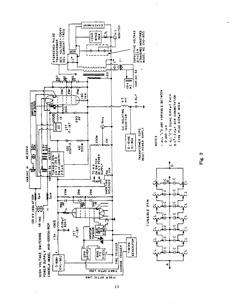
modulator successfully handled the reflected power. A block diagram of the modulator is
shown in Fig. 1 and a schematic diagram in Fig. 2.
II. Modulator Description
The modulator has the following parameters:
Peak Pulse Power 500 MW
Pulse Repetition Frequency 5 pps
Output Pulse Voltage 700 kV
Output Impedance 900 n
Pulse to Pulse Regulation 0.1%
Pulse Ripple, 1 ps flat-top 0.2%
The PFN is charged by a 10 kJ/sec, 0-80 kV resonant inverter power supply, with
0.1% regulation, giving a pulse repetition frequency of 5 pps. The modulator switch is an
ITT F-187 thyratron rated for 75 kV and 20 kA. Another F-187 is used for an end-of-line
2

clipper with a series 1.6 Q resistor to absorb the reflected energy when a short circuit
occurs.
The complete modulator is submersed in a stainless steel tank 8 ft. long by 4 ft. wide
by 4 ft. deep which is filled with transformer oil (Shell DIALAX). At the output end of the
modulator the tank has two 18 inch ports with O-ring flanges for attaching the cathode
stalks or electron guns employed in different experiments. All high voltage connections
to the experiments are made in oil. The tank is completely covered and interlocked for
personnel safety. The oil in the tank can be pumped through a three-stage filtration
system.
The transformer has a 20:1 turns ratio with bifilar windings on the secondary for
supplying filament power to the electron guns used as the load. The load used to test
the modulator and to use in parallel with high impedance experiments is a 975 Q resistor,
capable of dissipating 5 kW, made by the Stackpole Co. The resistor is made with thirty
30 Q disks all bolted together with a 0.5 inch phenolic rod. Each disk is 1 inch thick and
4.4 inches in diameter. After immersed in oil for a period of time, the resistance of the
resistor increased from the original 900 Q to 975 Q.
The PFN impedance of 2.25 Q is generated by using two Rayleigh type, 4.5 Q PFNs
in parallel. Each PFN has 7 sections and each section has an inductance variable between
0.2 and 1.2 p1H. The inductance can be changed in steps and also fine tuned between steps.
The capacitors are 40 nF each with low internal inductance and a rated voltage of 80 kV,
manufactured by Maxwell Laboratories. The maximum stray inductance external to the
PFN for it to retain tunability is 1.3 pH.
The sections of the PFN are separated by 6 inches to minimize mutual inductance
between coils. The calculated mutual inductance between coils is 30 nH. With the Rayleigh-
type PFN the pulse width can be reduced, if desired, by removing sections.
The PFN is charged with a voltage regulated constant energy, 10 kJ/sec, power supply.
The power supply has two modes of operation, continuous run and command arm/fire. We
3
use the arm and fire mode in the experiment. Figure 3 shows the charging-firing cycle for
three different charging voltages (40, 44, 48 kV). Upon receiving the charge command,
the voltage is charged up linearly to the desired value and held high until the firing pulse
dumps the energy.
The clipper thyratron has very low inductance, 75 nH, and is rated for 75 kV at 20
kA. The low inductance (thyratron inductance plus stray inductances) is very important
since it determines how fast the reflected energy can be removed. A critical rating of the
switch thyratron is its peak inverse voltage, immediately after forward conduction, which
for the F-187 is 10 kV. If the reverse voltage is allowed to exceed 10 kV, arcing may occur
which is very harmful to the thyratron and may cause its demise.
Since the experiments that this modulator will be driving run at a low repetition
frequency, it was decided to use a voltage regulated, resonant inverter constant energy
power supply rather than resonant charging with de-Qing. The voltage waveshape on the
PFN is shown in Fig. 4.
The modulator PFN is discharged through an ITT F-187 thyratron into a 1:20 pulse
transformer which gives an output voltage up to 700 kV into the load. When an experiment
with an impedance higher than 900 Q is used an appropriate resistor is used in parallel to
bring the total secondary load close to 900 Q. If the experimental load is less than 900
Q, any reflected power is absorbed by the clipper circuits. The pulse shape of the PFN is
easily varied to give any desired shape to the top of the pulse. The modulator functioned
as designed and has been tested to 625 kV on a 975 Q load. The output waveform is shown
in Fig. 4. For this test, the charging voltage was 61 kV.
At high voltages, the relativistic magnetron tends to short circuit a few hundred
nanoseconds into the pulse [1], the clipper circuits (thyratron plus diode) then absorb all
of the reflected energy. The thyratron clipper is automatically triggered and works very
well provided the external inductance is kept low. The solid state clipper that is used in
parallel with the thyratron (see Fig. 2) has three EDI model ED-2212 diode stacks in series
with a total inverse voltage rating of 225 kV and a 50 kA peak current rating. The diode
4
stack successfully takes out part of the reflected power as designed. However, if the diode
stack is used alone - without the thyratron -, it is too slow to absorb all of the reflected
energy.
A capacitive voltage divider is used to measure the high voltage pulse on the secondary
of the pulse transformer. The capacitive voltage divider is a Stangenes model CVD-800
rated for a peak voltage of 800 kV and 12200:1 voltage division. The results using the
probe have been very satisfactory although care has to be taken not to change cable length
after the probe has been calibrated. A second method used to measure the high voltage
pulse is to measure the current through the 975 f secondary load using a Rogowski current
transformer. This method proves to be difficult to calibrate because the resistance value
of the carbon resistor that we use for a load varies with voltage at these high voltages.
III. Operation with a Relativistic Magnetron
The modulator has been used to drive a high power, long pulse relativistic magnetron
experiment [1,2,3]. The [is pulses are more than 20 times longer than in all previous
relativistic magnetron experiments and it is essential for injection locking of high power
oscillators. Interesting diode impedance variations were observed in the experiment [1],
which owe their origin to the emission characteristics of the cold cathode in the relativistic
magnetron diode under crossed electric, magnetic and strong rf fields. The magnetron
impedance Z of a cold-cathode field-emission system is determined by the interplay between
the following processes: (1) the nonlinear field emission process under the applied anode
voltage V , and (2) the magnetic insulation process under the applied transverse magnetic
field B. The impedance can be written as a function of the relevant variables:
Z = Z(V, B, ,9, ...) (1)
where g is the anode-cathode gap. It should be noted that the anode voltage, in turn,
depends on the magnetron impedance
2 zV = V..tced - Z (2)
(1+ Z)p.s..
5
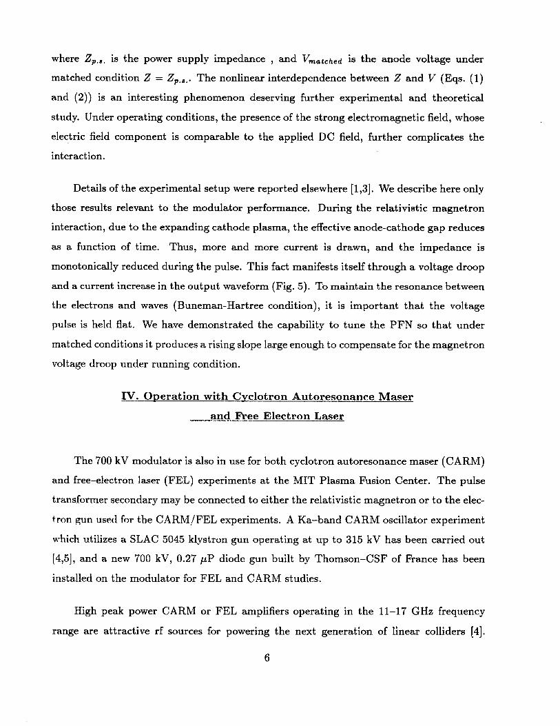
where Z,.,. is the power supply impedance , and Vmatched is the anode voltage under
matched condition Z = Z,.,.. The nonlinear interdependence between Z and V (Eqs. (1)
and (2)) is an interesting phenomenon deserving further experimental and theoretical
study. Under operating conditions, the presence of the strong electromagnetic field, whose
electric field component is comparable to the applied DC field, further complicates the
interaction.
Details of the experimental setup were reported elsewhere [1,3]. We describe here only
those results relevant to the modulator performance. During the relativistic magnetron
interaction, due to the expanding cathode plasma, the effective anode-cathode gap reduces
as a function of time. Thus, more and more current is drawn, and the impedance is
monotonically reduced during the pulse. This fact manifests itself through a voltage droop
and a current increase in the output waveform (Fig. 5). To maintain the resonance between
the electrons and waves (Buneman-Hartree condition), it is important that the voltage
pulse is held flat. We have demonstrated the capability to tune the PFN so that under
matched conditions it produces a rising slope large enough to compensate for the magnetron
voltage droop under running condition.
IV. Operation with Cyclotron Autoresonance Maser
and Free Electron Laser
The 700 kV modulator is also in use for both cyclotron autoresonance maser (CARM)
and free-electron laser (FEL) experiments at the MIT Plasma Fusion Center. The pulse
transformer secondary may be connected to either the relativistic magnetron or to the elec-
tron gun used for the CARM/FEL experiments. A Ka-band CARM oscillator experiment
which utilizes a SLAC 5045 klystron gun operating at up to 315 kV has been carried out
[4,5], and a new 700 kV, 0.27 pP diode gun built by Thomson-CSF of France has been
installed on the modulator for FEL and CARM studies.
High peak power CARM or FEL amplifiers operating in the 11-17 GHz frequency
range are attractive rf sources for powering the next generation of linear colliders [4].
6

The long pulse width (relative to linear induction accelerators) and low voltage ripple
obtained with this type of pulse modulator are important for achieving the rf phase stability
required of rf-accelerator drivers [6]. The rf output from modulator-driven CARM or FEL
amplifiers with microsecond pulse lengths can be pulse-compressed to obtain higher peak
powers in shorter pulses if necessary [7].
High voltage modulator-driven CARMs or FELs may also be attractive as sources
of high average power in the 140-280 GHz frequency range for use in electron-cyclotron
resonance heating (ECRH) of fusion plasmas. Burst mode operation of modulator driven
CARMs or FELs with 0.5-1 MeV beam energies, currents of -1 kA, and duty factors of
0.1% to 0.5% may be attractive for megawatt average power level ECRH sources.
V. Discussion
The modulator has performed very satisfactorily under all types of loads. The electron
gun in the CARM oscillator experiment behaves like a matched load, and the modulator
delivered flat voltage pulses reliably. When used in the cold-cathode relativistic mag-
netron experiment, the modulator performed as designed even with the time-dependent
load impedance. When the magnetron impedance collapsed to a very low value before the
end of the modulator pulse, the modulator successfully absorbed the reflected power.
Several improvements to this modulator are planned. In order to drive rf sources of
different characteristic impedances, the pulse transformer will be modified into a multi-
impedance transformer with four different impedance taps (20:1, 12:1, 8:1, 5:1). More
efficient power transfer from the modulator to the rf sources is expected. The clipper
circuits will be greatly simplified with the installation of low inductance solid state diodes
which allow us to avoid the clipper thyratron and its complex peripheral circuitry.
VI. Acknowledgement
This work was supported by Strategic Defense Initiative Organization, Office of Innovative
Science and Technology, and managed by Harry Diamond Laboratories.
7
Reference
[1] S.C. Chen, G. Bekefi, and R. Temkin, "Operation of a long pulse relativistic magnetron
in a phase-locking system," Proc. SPIE, vol. 1226, pp 36-43, 1990.
[2] S.C. Chen and G. Bekefi, "Relativistic magnetron research," N. Rostoker, Editor, Proc.
SPIE, vol. 873, pp 18-22, 1988.
[3] S.C. Chen, G. Bekefi, R. Temkin, and C. de Graff, "Proposed injection locking of a long
pulse relativistic magnetron," H.E. Brandt, Editor, Proc. SPIE, vol. 1061, pp. 157-160,
1989.
[4] B.G. Danly, J.S. Wurtele, K.D. Pendergast, and R.J. Temkin, "CARM driver for high
frequency rf accelerators," Proceedings of the 1989 IEEE Particle Accelerator Conference,
vol. 1, pp.223-225, 1989.
[5] K.D. Pendergast, et al., in preparation.
[6] P.B. Wilson, "High pulse power rf sources for linear colliders," SLAC-PUB-3227, 1983.
[7] Z.D. Farkas and J.N. Weaver, "RF pulse compression development," SLAC-AP-59,
1987.
8

Figure Caption
Fig. 1 Block diagram of the MIT 700 kV modulator
Fig. 2 Schematic diagram of the MIT 700 kV modulator
Fig. 3 Charging-firing cycle for three different charging voltages (40, 44, 48 kV). Upon re-
ceiving the charge command, the voltage is charged up linearly to the desired value
and held high until the firing pulse dumps the energy. Time - 50 ms/div, voltage -
10 kV/div.
Fig. 4 Secondary voltage waveform across a matched load. With a charging voltage of 61
kV, the output flat-top voltage is 625 kV. Time - 500 ns/div, voltage - 97.5 kV/div.
Fig. 5 Voltage and current waveforms of a cold-cathode relativistic magnetron. The mod-
ulator was charged up to 20 kV, and a 8:1 pulse transformer is used. Due to the
expanding cathode plasma, more and more current is drawn and the impedance is
monotonically reduced during the pulse. This fact manifests itself through a voltage
droop (lower trace) and a current increase (upper trace). Time - 500 ns/div, voltage
- 19.2 kV/div, current 200 A/div.
9

Power PFN
SupplyDid
ThyratronlipperS w ir t c hT h r a r o
R e ei erClpp r Transform er L a
Pulse Delay Generator Optical Core Reset& Fiber Optic Receiver Power SupplyTransmitter
Fig. 1
10
0NNNw
.4
x
g L
0 -
U,
0
to 00
-w
IN 3Pi 3dX 3
w 80aC1,4 -
Z 0 -Jx
0 (Al >Uzz
U) I-- U) cn
=~0
I I.
IxI08
C:N
or
C LL.
0 L)100
CI t2inJ
Z
x 10fn U)
T -2 6
w" 6i,ox
00
> >)
.> 0
U-cn
U)
z
U) M
>0
00 00CL-a
zIA.0.
w-j
4zD-
0
0 w-z
I-X (D
L-
-cc
U)
0z
zww3-
w-a
w
4 z4
0
U.
0
o
0
-J
z0
2
4
(-
o
U:L
N
02
0.
w0.
0
(~) (.)m
L) U-I
U U -a
U U.4
U U .~1
U U -a
o U.4
4
11
Cb1
z
w
0
:E
I.-
-I0
0w
.0
00.
XNI-l OlIdO J381.4

Fig. 3
12

Fig. 4
13

Fig. 5
14