Peugeot 405 (petrol) Service and Repair Manual · The Peugeot 405 model range was introduced into...
301
Models covered Saloon and Estate models with 4-cylinder SOHC and DOHC petrol engines, including Mi-16 and special/limited editions; 1.4 (1360 cc), 1.6 (1580 cc), 1.8 (1761 cc), 1.9 (1905 cc) and 2.0 (1998 cc) For Diesel engine models, see OWM 3198 Does not cover four-wheel-drive models © Haynes Publishing 1996 A book in the Haynes Service and Repair Manual Series All rights reserved. No part of this book may be reproduced or transmitted in any form or by any means, electronic or mechanical, including photocopying, recording or by any information storage or retrieval system, without permission in writing from the copyright holder. ISBN 1 85960 174 X British Library Cataloguing in Publication Data A catalogue record for this book is available from the British Library. Printed by J H Haynes & Co. Ltd, Sparkford, Nr Yeovil, Somerset BA22 7JJ Haynes Publishing Sparkford, Nr Yeovil, Somerset BA22 7JJ, England Haynes North America, Inc 861 Lawrence Drive, Newbury Park, California 91320, USA Editions Haynes S.A. 147/149, rue Saint Honoré, 75001 PARIS, France Peugeot 405 (petrol) Service and Repair Manual Steve Rendle and A K Legg LAE MIMI (1559-336)
Transcript of Peugeot 405 (petrol) Service and Repair Manual · The Peugeot 405 model range was introduced into...
Models coveredSaloon and Estate models with 4-cylinder SOHC and DOHC petrol engines, including Mi-16 and special/limited editions;1.4 (1360 cc), 1.6 (1580 cc), 1.8 (1761 cc), 1.9 (1905 cc) and 2.0 (1998 cc)
For Diesel engine models, see OWM 3198Does not cover four-wheel-drive models
© Haynes Publishing 1996
A book in the Haynes Service and Repair Manual Series
All rights reserved. No part of this book may be reproduced or transmittedin any form or by any means, electronic or mechanical, includingphotocopying, recording or by any information storage or retrieval system,without permission in writing from the copyright holder.
ISBN 1 85960 174 X
British Library Cataloguing in Publication DataA catalogue record for this book is available from the British Library.
Printed by J H Haynes & Co. Ltd, Sparkford, Nr Yeovil,
Somerset BA22 7JJ
Haynes Publishing
Sparkford, Nr Yeovil, Somerset BA22 7JJ, England
Haynes North America, Inc
861 Lawrence Drive, Newbury Park, California 91320, USA
Editions Haynes S.A.
147/149, rue Saint Honoré, 75001 PARIS, France
Peugeot 405 (petrol)Service and Repair ManualSteve Rendle and A K Legg LAE MIMI
(1559-336)

LIVING WITH YOUR PEUGEOT 405Introduction to the Peugeot 405 Page 0•4
Safety first! Page 0•5
Roadside RepairsIf your car won’t start Page 0•6
Jump starting Page 0•7
Wheel changing Page 0•8
Identifying leaks Page 0•9
Towing Page 0•9
Weekly ChecksIntroduction Page 0•10
Underbonnet check points Page 0•10
Engine oil level Page 0•12
Coolant level Page 0•12
Brake fluid level Page 0•13
Power steering fluid level Page 0•13
Tyre condition and pressure Page 0•14
Screen washer fluid level Page 0•15
Wiper blades Page 0•15
Battery Page 0•16
Bulbs and fuses Page 0•16
Lubricants, fluids and tyre pressures Page 0•17
MAINTENANCE
Routine Maintenance and ServicingPeugeot 405 petrol models Page 1•1
Maintenance schedule - models up to 1993 Page 1•3
Maintenance schedule - models from 1994 Page 1•4
Maintenance procedures Page 1•8
Contents

REPAIRS AND OVERHAUL
Engine and Associated SystemsTU petrol engine in-car repair procedures Page 2A•1
XU petrol engine in-car repair procedures Page 2B•1
Engine removal and overhaul procedures Page 2C•1
Cooling, heating and ventilation systems Page 3•1
Fuel/exhaust systems - carburettor models Page 4A•1
Fuel/exhaust systems - single-point fuel injection models Page 4B•1
Fuel/exhaust systems - multi-point fuel injection models Page 4C•1
Emission control systems Page 4D•1
Starting and charging systems Page 5A•1
Ignition system Page 5B•1
TransmissionClutch Page 6•1
Manual transmission Page 7A•1
Automatic transmission Page 7B•1
Driveshafts Page 8•1
Brakes and SuspensionBraking system Page 9•1
Suspension and steering Page 10•1
Body equipmentBodywork and fittings Page 11•1
Body electrical systems Page 12•1
Wiring Diagrams Page 12•22
REFERENCEDimensions and weights Page REF•1
Conversion factors Page REF•2
Buying spare parts and vehicle identification Page REF•3
General repair procedures Page REF•4
Jacking and vehicle support Page REF•5
Radio/cassette unit anti-theft system - precaution Page REF•5
Tools and working facilities Page REF•6
MOT test checks Page REF•8
Fault finding Page REF•12
Glossary of technical terms Page REF•20
Index Page REF•25
Contents

The Peugeot 405 model range was introduced into the UK inJanuary 1988 in Saloon form only.
Available with 1.6, 1.8, 1.9 and 2.0 engines, all models have front-wheel-drive with all round independent suspension.
Automatic transmission models were introduced in April 1988.In July 1988 came the sporty Mi 16 version with its 1.9 litre double
overhead cam, 16-valve engine, uprated gearbox, suspension and anABS braking system to match its power.
Estate car versions were introduced in October 1988.From 1991, engines equipped with catalytic converters were
progressively introduced, to meet the more stringent exhaust gasemission regulations.
Since its introduction, the 405 range has continually beendeveloped. All models have a high trim level, which is verycomprehensive in the upper model range.
For the home mechanic, the Peugeot 405 is a straightforwardvehicle to maintain and repair since design features have beenincorporated to reduce the actual cost of ownership to a minimum, andmost of the items requiring frequent attention are easily accessible.
Your Peugeot 405 ManualThe aim of this manual is to help you get the best value from your
vehicle. It can do so in several ways. It can help you decide what workmust be done (even should you choose to get it done by a garage),provide information on routine maintenance and servicing, and give alogical course of action and diagnosis when random faults occur.However, it is hoped that you will use the manual by tackling the workyourself. On simpler jobs, it may even be quicker than booking the carinto a garage and going there twice, to leave and collect it. Perhapsmost important, a lot of money can be saved by avoiding the costs agarage must charge to cover its labour and overheads.
The manual has drawings and descriptions to show the function ofthe various components, so that their layout can be understood. Thenthe tasks are described and photographed in a clear step-by-stepsequence.
0•4 Introduction
Peugeot 405 SRi Saloon Peugeot 405 GL Estate
AcknowledgementsThanks are due to Champion Spark Plug who supplied the
illustrations showing spark plug conditions. Certain other illustrationsare the copyright of the Peugeot Talbot Motor Company Limited, andare used with their permission. Special thanks to Gliddons of Tauntonwho provided several of the project vehicles used in the origination ofthis manual. Thanks are also due to Sykes-Pickavant Limited, whoprovided some of the workshop tools, and to all those people atSparkford who helped in the production of this manual.
We take great pride in the accuracy of information given in thismanual, but vehicle manufacturers make alterations and designchanges during the production run of a particular vehicle of whichthey do not inform us. No liability can be accepted by the authorsor publishers for loss, damage or injury caused by any errors in, oromissions from, the information given.
Project vehiclesThe vehicles used in the preparation of this manual, and which
appear in many of the photographic sequences, were a Peugeot 405GL Saloon, a Peugeot 405 GTX Estate, a Peugeot 405 GR Saloon, anda Peugeot GTX Saloon.
The Peugeot 405 TeamHaynes manuals are produced by dedicated andenthusiastic people working in close co-operation. Theteam responsible for the creation of this book included:
Authors Steve RendleAndy Legg
Sub-editor Carole Turk
Editor & Page Make-up Bob Jex
Workshop manager Paul Buckland
Photo Scans John MartinPaul Tanswell
Cover illustration & Line Art Roger Healing
Wiring diagrams Matthew Marke
We hope the book will help you to get the maximumenjoyment from your car. By carrying out routinemaintenance as described you will ensure your car’sreliability and preserve its resale value.
Safety First! 0•5
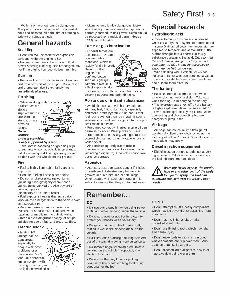
Working on your car can be dangerous.This page shows just some of the potentialrisks and hazards, with the aim of creating asafety-conscious attitude.
General hazardsScalding• Don’t remove the radiator or expansiontank cap while the engine is hot.• Engine oil, automatic transmission fluid orpower steering fluid may also be dangerouslyhot if the engine has recently been running.
Burning• Beware of burns from the exhaust systemand from any part of the engine. Brake discsand drums can also be extremely hotimmediately after use.
Crushing• When working under or neara raised vehicle,alwayssupplement thejack with axlestands, or usedrive-onramps.Neverventureunder a car whichis only supported by a jack.• Take care if loosening or tightening high-torque nuts when the vehicle is on stands.Initial loosening and final tightening shouldbe done with the wheels on the ground.
Fire• Fuel is highly flammable; fuel vapour isexplosive. • Don’t let fuel spill onto a hot engine. • Do not smoke or allow naked lights(including pilot lights) anywhere near avehicle being worked on. Also beware ofcreating sparks (electrically or by use of tools).• Fuel vapour is heavier than air, so don’twork on the fuel system with the vehicle overan inspection pit.• Another cause of fire is an electricaloverload or short-circuit. Take care whenrepairing or modifying the vehicle wiring.• Keep a fire extinguisher handy, of a typesuitable for use on fuel and electrical fires.
Electric shock • Ignition HTvoltage can bedangerous,especially topeople with heartproblems or apacemaker. Don’twork on or near theignition system withthe engine running orthe ignition switched on.
• Mains voltage is also dangerous. Makesure that any mains-operated equipment iscorrectly earthed. Mains power points shouldbe protected by a residual current device(RCD) circuit breaker.
Fume or gas intoxication • Exhaust fumes arepoisonous; they oftencontain carbonmonoxide, which israpidly fatal if inhaled.Never run theengine in aconfined spacesuch as a garagewith the doors shut.• Fuel vapour is alsopoisonous, as are the vapours from somecleaning solvents and paint thinners.
Poisonous or irritant substances• Avoid skin contact with battery acid andwith any fuel, fluid or lubricant, especiallyantifreeze, brake hydraulic fluid and Dieselfuel. Don’t syphon them by mouth. If such asubstance is swallowed or gets into the eyes,seek medical advice.• Prolonged contact with used engine oil cancause skin cancer. Wear gloves or use abarrier cream if necessary. Change out of oil-soaked clothes and do not keep oily rags inyour pocket.• Air conditioning refrigerant forms apoisonous gas if exposed to a naked flame(including a cigarette). It can also cause skinburns on contact.
Asbestos• Asbestos dust can cause cancer if inhaledor swallowed. Asbestos may be found ingaskets and in brake and clutch linings.When dealing with such components it issafest to assume that they contain asbestos.
Special hazardsHydrofluoric acid• This extremely corrosive acid is formedwhen certain types of synthetic rubber, foundin some O-rings, oil seals, fuel hoses etc, areexposed to temperatures above 4000C. Therubber changes into a charred or stickysubstance containing the acid. Once formed,the acid remains dangerous for years. If itgets onto the skin, it may be necessary toamputate the limb concerned.• When dealing with a vehicle which hassuffered a fire, or with components salvagedfrom such a vehicle, wear protective glovesand discard them after use.
The battery• Batteries contain sulphuric acid, whichattacks clothing, eyes and skin. Take carewhen topping-up or carrying the battery.• The hydrogen gas given off by the batteryis highly explosive. Never cause a spark orallow a naked light nearby. Be careful whenconnecting and disconnecting batterychargers or jump leads.
Air bags• Air bags can cause injury if they go offaccidentally. Take care when removing thesteering wheel and/or facia. Special storageinstructions may apply.
Diesel injection equipment• Diesel injection pumps supply fuel at veryhigh pressure. Take care when working onthe fuel injectors and fuel pipes.
Warning: Never expose the hands,face or any other part of the bodyto injector spray; the fuel can
penetrate the skin with potentially fatalresults.
Remember...DO• Do use eye protection when using powertools, and when working under the vehicle.
• Do wear gloves or use barrier cream toprotect your hands when necessary.
• Do get someone to check periodicallythat all is well when working alone on thevehicle.
• Do keep loose clothing and long hair wellout of the way of moving mechanical parts.
• Do remove rings, wristwatch etc, beforeworking on the vehicle – especially theelectrical system.
• Do ensure that any lifting or jackingequipment has a safe working load ratingadequate for the job.
A few tipsDON’T• Don’t attempt to lift a heavy componentwhich may be beyond your capability – getassistance.
• Don’t rush to finish a job, or takeunverified short cuts.
• Don’t use ill-fitting tools which may slipand cause injury.
• Don’t leave tools or parts lying aroundwhere someone can trip over them. Mopup oil and fuel spills at once.
• Don’t allow children or pets to play in ornear a vehicle being worked on.

0•6 Roadside RepairsThe following pages are intended to help in dealing with
common roadside emergencies and breakdowns. You will findmore detailed fault finding information at the back of themanual, and repair information in the main chapters.
If your car won’t start and the starter motordoesn’t turnM If it’s a model with automatic transmission, make sure the
selector is in ‘P’ or ‘N’.M Open the bonnet and make sure that the battery terminals
are clean and tight.M Switch on the headlights and try to start the engine. If the
headlights go very dim when you’re trying to start, thebattery is probably flat. Get out of trouble by jump starting(see next page) using a friend’s car.
If your car won’t start even though the startermotor turns as normalM Is there fuel in the tank?M Is there moisture on electrical components under the
bonnet? Switch off the ignition, then wipe off any obviousdampness with a dry cloth. Spray a water-repellent aerosolproduct (WD-40 or equivalent) on ignition and fuel systemelectrical connectors like those shown in the photos. Pay special attention to the ignition coil wiring connectorand HT leads. (Note that Diesel engines don’t normallysuffer from damp.)
Check that the spark plug HT leads(where applicable) are securelyconnected by pushing them home.
A The throttle potentiometer wiring plugmay cause problems if not connectedsecurely.
B Check the idle speed stepper motorwiring plug for security.C
Check the security and condition of thebattery connections.D
Check that the ignition coil wiring plug issecure, and spray with water-dispersantif necessary.
ECheck that electrical connections are secure (with the ignition switched off) and spray themwith a water dispersant spray like WD40 if you suspect a problem due to damp

Roadside Repairs 0•7
When jump-starting a car using abooster battery, observe the followingprecautions:
4 Before connecting the boosterbattery, make sure that the ignition isswitched off.
4 Ensure that all electrical equipment(lights, heater, wipers, etc) isswitched off.
4 Make sure that the booster battery isthe same voltage as the dischargedone in the vehicle.
4 If the battery is being jump-startedfrom the battery in another vehicle,the two vehcles MUST NOT TOUCHeach other.
4 Make sure that the transmission is inneutral (or PARK, in the case ofautomatic transmission).
Jump starting will get you outof trouble, but you must correctwhatever made the battery goflat in the first place. There are three possibilities:
1 The battery has been drained byrepeated attempts to start, or by
leaving the lights on.
2 The charging system is not workingproperly (alternator drivebelt slack
or broken, alternator wiring fault oralternator itself faulty).
3 The battery itself is at fault(electrolyte low, or battery worn out).
Connect one end of the red jump lead tothe positive (+) terminal of the flatbattery
Connect the other end of the red lead tothe positive (+) terminal of the boosterbattery.
Connect one end of the black jump leadto the negative (-) terminal of thebooster battery
Connect the other end of the blackjump lead to a bolt or bracket on theengine block, well away from thebattery, on the vehicle to be started.
1 2 3
4
Make sure that the jump leads will notcome into contact with the fan, drive-belts or other moving parts of theengine.
5
Start the engine using the boosterbattery, then with the engine running atidle speed, disconnect the jump leads inthe reverse order of connection.
6
Jump starting

In the boot, use the wheel brace toloosen the spare wheel cradle bolt.
0•8 Roadside Repairs
Wheel changingSome of the details shown here will varyaccording to model. For instance, the locationof the spare wheel and jack is not the sameon all cars. However, the basic principlesapply to all vehicles.
M When a puncture occurs, stop as soonas it is safe to do so.
M Park on firm level ground, if possible,and well out of the way of other traffic.
M Use hazard warning lights if necessary.
M If you have one, use a warning triangle toalert other drivers of your presence.
M Apply the handbrake and engage first orreverse gear.
M Chock the wheel diagonally opposite the
one being removed – a couple of largestones will do for this.
M If the ground is soft, use a flat piece ofwood to spread the load under the footof the jack.
Changing the wheel
Preparation
Warning: Do not change a wheel in a situation where you risk being hit byother traffic. On busy roads, try to stop in a lay-by or a gateway. Be wary ofpassing traffic while changing the wheel – it is easy to become distracted bythe job in hand.
Finally...M Remove the wheel chocks.
M Stow the jack and tools in the correct locations in the car.
M Make sure that the spare wheel cradle is properly secured, or it could drop onto the roadwhile driving.
M Check the tyre pressure on the wheel just fitted. If it is low, or if you don’t have a pressuregauge with you, drive slowly to the nearest garage and inflate the tyre to the right pressure.
M Have the damaged tyre or wheel repaired as soon as possible.
Before raising the car, loosen the wheelbolts slightly using the wheelbrace.
Locate the jack head in the jacking pointand use the brace to raise the car untilthe wheel is clear of the ground.
Temporarily place the spare wheel underthe sill as a precaution should the jacktopple.
Use the wheel brace to remove the wheeltrim.
Remove the spare wheel from the cradle.1 2 3
4 5 6
Remove the bolts and remove the wheel.Fit the spare wheel and hand-tighten thebolts. Lower the car, then tighten the
wheel bolts firmly. Have the bolts tightened tothe correct torque at the earliest opportunity.
7

Roadside Repairs 0•9
When all else fails, you may find yourselfhaving to get a tow home – or of course youmay be helping somebody else. Long-distancerecovery should only be done by a garage orbreakdown service. For shorter distances, DIYtowing using another car is easy enough, butobserve the following points:M Use a proper tow-rope – they are notexpensive. The vehicle being towed mustdisplay an ‘ON TOW’ sign in its rear window.M Always turn the ignition key to the ‘on’position when the vehicle is being towed, so
that the steering lock is released, and that thedirection indicator and brake lights will work.M Only attach the tow-rope to the towingeyes provided.M Before being towed, release the handbrakeand select neutral on the transmission.M Note that greater-than-usual pedalpressure will be required to operate thebrakes, since the vacuum servo unit is onlyoperational with the engine running.M On models with power steering, greater-than-usual steering effort will also be required.
M The driver of the car being towed mustkeep the tow-rope taut at all times to avoidsnatching.M Make sure that both drivers know the routebefore setting off.M Only drive at moderate speeds and keepthe distance towed to a minimum. Drivesmoothly and allow plenty of time for slowingdown at junctions.M On models with automatic transmission,special precautions apply. If in doubt, do nottow, or transmission damage may result.
Towing
Puddles on the garage floor or drive, orobvious wetness under the bonnet or underneath the car, suggest a leak that needsinvestigating. It can sometimes be difficult todecide where the leak is coming from,especially if the engine bay is very dirtyalready. Leaking oil or fluid can also be blownrearwards by the passage of air under the car,giving a false impression of where theproblem lies.
Warning: Most automotive oilsand fluids are poisonous. Washthem off skin, and change out ofcontaminated clothing, withoutdelay.
Identifying leaksThe smell of a fluid leakingfrom the car may provide aclue to what’s leaking. Somefluids are distinctively
coloured. It may help to clean the carcarefully and to park it over some cleanpaper overnight as an aid to locating thesource of the leak.Remember that some leaks may onlyoccur while the engine is running.
Sump oil Gearbox oil
Brake fluid Power steering fluid
Oil from filter
Antifreeze
Engine oil may leak from the drain plug... ...or from the base of the oil filter.
Leaking antifreeze often leaves a crystallinedeposit like this.
Gearbox oil can leak from the seals at theinboard ends of the driveshafts.
A leak occurring at a wheel is almostcertainly brake fluid.
Power steering fluid may leak from the pipeconnectors on the steering rack.
0•10 Weekly Checks
There are some very simple checks whichneed only take a few minutes to carry out, butwhich could save you a lot of inconvenienceand expense.
These "Weekly checks" require no great skillor special tools, and the small amount of timethey take to perform could prove to be verywell spent.
M Keeping an eye on tyre condition andpressures, will not only help to stop themwearing out prematurely, but could also saveyour life.
M Many breakdowns are caused by electricalproblems. Battery-related faults are particularlycommon, and a quick check on a regular basiswill often prevent the majority of these.
M If your car develops a brake fluid leak, thefirst time you might know about it is whenyour brakes don't work properly. Checkingthe level regularly will give advance warning ofthis kind of problem.M If the oil or coolant levels run low, the costof repairing any engine damage will be fargreater than fixing the leak, for example.
Introduction
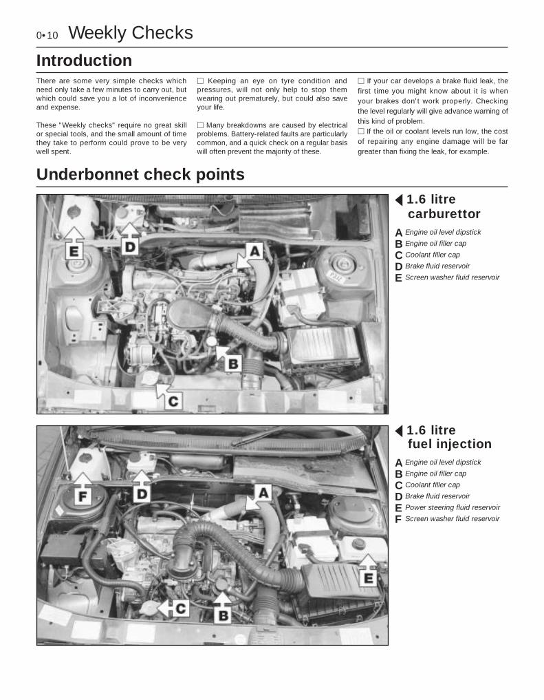
§ 1.6 litrecarburettor
A Engine oil level dipstick
B Engine oil filler cap
C Coolant filler cap
D Brake fluid reservoir
E Screen washer fluid reservoir
Underbonnet check points
§ 1.6 litrefuel injection
A Engine oil level dipstick
B Engine oil filler cap
C Coolant filler cap
D Brake fluid reservoir
E Power steering fluid reservoir
F Screen washer fluid reservoir

Weekly Checks 0•11
§ 1.9 litreA Engine oil level dipstick
B Engine oil filler cap
C Coolant filler cap
D Brake fluid reservoir
E Power steering fluid reservoir
F Screen washer fluid reservoir
§ 2.0 litreA Engine oil level dipstick
B Engine oil filler cap
C Coolant filler cap
D Brake fluid reservoir
E Power steering fluid reservoir
F Screen washer fluid reservoir

0•12 Weekly Checks
Warning: DO NOT attempt toremove the expansion tankpressure cap when the engineis hot, as there is a very greatrisk of scalding. Do not leaveopen containers of coolant
about, as it is poisonous.
Car Carel With a sealed-type cooling system,adding coolant should not be necessary on aregular basis. If frequent topping-up isrequired, it is likely there is a leak. Check theradiator, all hoses and joint faces for signs ofstaining or wetness, and rectify as necessary.
l It is important that antifreeze is used inthe cooling system all year round, not justduring the winter months. Don’t top-up withwater alone, as the antifreeze will becometoo diluted.
Coolant level
The coolant level varies with enginetemperature. When cold, the coolantlevel should be on the “MAXI” mark
(arrowed). When the engine is hot, the levelmay rise slightly above the “MAXI” mark.
If topping up is necessary, wait until theengine is cold. Unscrew the expansiontank cap to the first stop, to release any
pressure present in the system. Push the capdown, turn to the second stop, and remove it.
Add a mixture of water and antifreezethrough the expansion tank filler neck,until the coolant level is up to the “MAXI”
level mark. Refit the cap, turning it clockwiseas far as it will go to secure.
1 2 3
Engine oil levelBefore you start4 Make sure your car is on level ground.4 Check the oil level before the car is driven,or at least 5 minutes after the engine has beenswitched off.
The correct oilModern engines place great demands on theiroil. It is very important that the correct oil foryour car is used (See “Lubricants, fluids andtyre pressures”).
Car Carel If you have to add oil frequently, youshould check whether you have any oil leaks.Place some clean paper under the carovernight, and check for stains in the morning.If there are no leaks, the engine may beburning oil (see “Fault Finding”).
l Always maintain the level between theupper and lower dipstick marks (see photo 3).If the level is too low severe engine damagemay occur. Oil seal failure may result if theengine is overfilled by adding too much oil.
If the oil is checkedimmediately after driving thevehicle, some of the oil willremain in the upper engine
components, resulting in an inaccuratereading on the dipstick!
The dipstick top is often brightly colouredfor easy identification (see “Underbonnetcheck points” on pages 0•10 and 0•11
for exact location). Withdraw the dipstick.
Using a clean rag or paper towel removeall oil from the dipstick. Insert the cleandipstick into the tube as far as it will go,
then withdraw it again.
Note the oil level on the end of thedipstick, which should be between theupper ("MAX") mark and lower ("MIN")
mark. Approximately 1.0 litre of oil will raisethe level from the lower mark to the uppermark.
Oil is added through the filler cap.Unscrew the cap and top-up the level; afunnel may help to reduce spillage. Add
the oil slowly, checking the level on the dipstickoften. Don’t overfill (see “Car Care” left).
1 2
3 4

Weekly Checks 0•13
Brake fluid levelWarning: Brake fluid can harmyour eyes and damage paintedsurfaces, so use extremecaution when handling andpouring it.
Warning: Do not use fluid that has beenstanding open for some time, as it absorbsmoisture from the air, which can cause adangerous loss of braking effectiveness.
Before you start:4 Park the vehicle on level ground.
4 On models with ABS (anti-lock brakes),switch the ignition off and pump the brakepedal at least 20 times or until the pedalfeels hard. Open the bonnet. Switch onthe ignition: the hydraulic unit pump willbe heard running. Wait until the pumpstops, then switch off the ignition.
Safety First!l If the reservoir requires repeated topping-up this is an indication of a fluid leaksomewhere in the system, which should beinvestigated immediately. l If a leak is suspected, the car should notbe driven until the braking system has beenchecked. Never take any risks where brakesare concerned.
The fluid level in the reservoirwill drop slightly as the brakepads wear down, but thefluid level must never be
allowed to drop below the “MIN” mark.
The “MAX” (A) and “DANGER” (B) marksare indicated on the side of the reservoir,which is located in the scuttle at the reardriver’s side of the engine compartment.
The fluid level must be kept between thesetwo marks.
1 If topping-up is necessary, first wipe thearea around the filler cap with a clean ragbefore removing the cap. Check the fluid
already in the reservoir - the system should bedrained and refilled if dirt is seen in the fluid(see Chapter 9 for details).
2
Carefully add fluid, avoiding spilling it onsurrounding paintwork. Use only thespecified hydraulic fluid; mixing different
types of fluid can cause damage to thesystem and/or a loss of braking effectiveness.After filling to the correct level, refit the capsecurely. Wipe off any spilt fluid.
3 Check the operation of the low fluid levelwarning light. Chock the roadwheels,release the handbrake, and switch on the
ignition. Ask an assistant to press the button ontop of the reservoir. The brake fluid level/handbrake warning light should come on. Applythe handbrake and switch off the ignition
4
Power steering fluid levelBefore you start:4 Park the car on level ground.4 Set the steering wheel straight-ahead.4 The engine should be turned off.
Safety First! l The need for frequent topping-upindicates a leak, which should be investigatedimmediately.
For the check to beaccurate, the steering mustnot be turned once theengine has been stopped.
The fluid level is visible through thetranslucent material of the reservoir, andshould be between the maximum (A) and
minimum (B) level lines marked on the side ofthe reservoir.
1 If topping-up is necessary, and beforeremoving the cap, wipe the area so thatdirt does not enter the reservoir. Unscrew
the cap, allowing the fluid to drain from thebottom of the cap as it is removed.
2 Top-up to the “MAX” mark, using thespecified type of fluid. Take great carenot to allow dirt to enter the reservoir,
and do not overfill the reservoir. When thelevel is correct, refit the cap.
3

0•14 Weekly Checks
Tyre condition and pressureIt is very important that tyres are in goodcondition, and at the correct pressure - havinga tyre failure at any speed is highly dangerous.Tyre wear is influenced by driving style - harshbraking and acceleration, or fast cornering,will all produce more rapid tyre wear. As ageneral rule, the front tyres wear out fasterthan the rears. Interchanging the tyres fromfront to rear ("rotating" the tyres) may result inmore even wear. However, if this iscompletely effective, you may have theexpense of replacing all four tyres at once!Remove any nails or stones embedded in thetread before they penetrate the tyre to causedeflation. If removal of a nail does reveal that
the tyre has been punctured, refit the nail sothat its point of penetration is marked. Thenimmediately change the wheel, and have thetyre repaired by a tyre dealer.Regularly check the tyres for damage in theform of cuts or bulges, especially in thesidewalls. Periodically remove the wheels,and clean any dirt or mud from the inside andoutside surfaces. Examine the wheel rims forsigns of rusting, corrosion or other damage.Light alloy wheels are easily damaged by"kerbing" whilst parking; steel wheels mayalso become dented or buckled. A new wheelis very often the only way to overcome severedamage.
New tyres should be balanced when they arefitted, but it may become necessary to re-balance them as they wear, or if the balanceweights fitted to the wheel rim should fall off.Unbalanced tyres will wear more quickly, aswill the steering and suspension components.Wheel imbalance is normally signified byvibration, particularly at a certain speed(typically around 50 mph). If this vibration isfelt only through the steering, then it is likelythat just the front wheels need balancing. If,however, the vibration is felt through thewhole car, the rear wheels could be out ofbalance. Wheel balancing should be carriedout by a tyre dealer or garage.
Tread Depth - visual checkThe original tyres have tread wear safety
bands (B), which will appear when the treaddepth reaches approximately 1.6 mm. Theband positions are indicated by a triangularmark on the tyre sidewall (A).
1 Tread Depth - manual checkAlternatively, tread wear can be
monitored with a simple, inexpensive deviceknown as a tread depth indicator gauge.
2 Tyre Pressure CheckCheck the tyre pressures regularly with
the tyres cold. Do not adjust the tyrepressures immediately after the vehicle hasbeen used, or an inaccurate setting will result.
3
Tyre tread wear patterns
Shoulder Wear
Underinflation (wear on both sides)Under-inflation will cause overheating of thetyre, because the tyre will flex too much, andthe tread will not sit correctly on the roadsurface. This will cause a loss of grip andexcessive wear, not to mention the danger ofsudden tyre failure due to heat build-up.Check and adjust pressuresIncorrect wheel camber (wear on one side)Repair or renew suspension partsHard corneringReduce speed!
Centre Wear
OverinflationOver-inflation will cause rapid wear of thecentre part of the tyre tread, coupled withreduced grip, harsher ride, and the danger ofshock damage occurring in the tyre casing.Check and adjust pressures
If you sometimes have to inflate your car’styres to the higher pressures specified formaximum load or sustained high speed, don’tforget to reduce the pressures to normalafterwards.
Uneven Wear
Front tyres may wear unevenly as a result ofwheel misalignment. Most tyre dealers andgarages can check and adjust the wheelalignment (or "tracking") for a modest charge.Incorrect camber or castorRepair or renew suspension partsMalfunctioning suspensionRepair or renew suspension partsUnbalanced wheelBalance tyresIncorrect toe settingAdjust front wheel alignmentNote: The feathered edge of the tread whichtypifies toe wear is best checked by feel.

Weekly Checks 0•15
Wiper blades
Check the condition of the wiper blades;if they are cracked or show any signs ofdeterioration, or if the glass swept area is
smeared, renew them. For maximum clarity ofvision, wiper blades should be renewedannually, as a matter of course. To remove afront wiper blade, first prise off the securingclips, and disconnect the washer tube fromthe arm.
1 Pull the arm fully away from the glassuntil it locks. Swivel the blade through90°, then pull up the blade securing clip,
and slide the blade out of the arm’s hookedend.
2 On Estate models, to remove a tailgatewiper blade, pull the arm fully away fromthe glass until it locks. Swivel the blade
through 90°, then press the locking tab, andslide the blade out of the arm’s hooked end.
3
Screenwash additives not only keep thewinscreen clean during foul weather, they alsoprevent the washer system freezing in cold
weather - which is when you are likely to needit most. Don’t top up using plain water as thescreenwash will become too diluted, and will
freeze during cold weather. On no accountuse coolant antifreeze in the washer system- this could discolour or damage paintwork.
Screen washer fluid level
On Estate models, the tailgate washerfluid reservoir is located behind a hingedcover on the right-hand side of the
luggage compartment.
2The windscreen/headlight washer fluidreservoir is located in the scuttle at therear right-hand corner of the engine
compartment.
1 When topping-up the reservoir(s) ascreenwash additive should be added inthe quantities recommended on the
bottle.
3
0•16 Weekly Checks
Bulbs and fuses
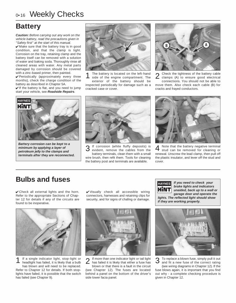
4 Check all external lights and the horn.Refer to the appropriate Sections of Chap-ter 12 for details if any of the circuits arefound to be inoperative.
4 Visually check all accessible wiringconnectors, harnesses and retaining clips forsecurity, and for signs of chafing or damage.
If you need to check yourbrake lights and indicatorsunaided, back up to a wall orgarage door and operate the
lights. The reflected light should showif they are working properly.
If a single indicator light, stop-light orheadlight has failed, it is likely that a bulbhas blown and will need to be replaced.
Refer to Chapter 12 for details. If both stop-lights have failed, it is possible that the switchhas failed (see Chapter 9).
If more than one indicator light or tail lighthas failed it is likely that either a fuse hasblown or that there is a fault in the circuit
(see Chapter 12). The fuses are locatedbehind a panel on the bottom of the driver’sside lower facia panel.
2 To replace a blown fuse, simply pull it outand fit a new fuse of the correct rating(see wiring diagrams in Chapter 12). If the
fuse blows again, it is important that you findout why - a complete checking procedure isgiven in Chapter 12.
31
BatteryCaution: Before carrying out any work on thevehicle battery, read the precautions given in"Safety first" at the start of this manual.4 Make sure that the battery tray is in goodcondition, and that the clamp is tight.Corrosion on the tray, retaining clamp and thebattery itself can be removed with a solutionof water and baking soda. Thoroughly rinse allcleaned areas with water. Any metal partsdamaged by corrosion should be coveredwith a zinc-based primer, then painted.4 Periodically (approximately every threemonths), check the charge condition of thebattery as described in Chapter 5A.4 If the battery is flat, and you need to jumpstart your vehicle, see Roadside Repairs.
The battery is located on the left-handside of the engine compartment. Theexterior of the battery should be
inspected periodically for damage such as acracked case or cover.
1 Check the tightness of the battery cableclamps (A) to ensure good electricalconnections. You should not be able to
move them. Also check each cable (B) forcracks and frayed conductors.
2
Battery corrosion can be kept to aminimum by applying a layer ofpetroleum jelly to the clamps andterminals after they are reconnected.
If corrosion (white fluffy deposits) isevident, remove the cables from thebattery terminals, clean them with a small
wire brush, then refit them. Tools for cleaningthe battery post and terminals are available.
3 Note that the battery negative terminalstud can be removed for cleaning or
renewal. Unscrew the lead clamp, then pull offthe plastic insulator, and lever off the stud andcover.
4

Lubricants and fluids
Lubricants, fluids and tyre pressures 0•17
Engine . . . . . . . . . . . . . . . . . . . . . . . . . . . . . . . . . . . Multigrade engine oil, viscosity SAE 10W/40 to20W/50, to API SG/CD or better
Cooling system . . . . . . . . . . . . . . . . . . . . . . . . . . . . Ethylene glycol based antifreezeManual transmission . . . . . . . . . . . . . . . . . . . . . . . . Gear oil, viscosity 75W/80W, to API GL5Automatic transmission . . . . . . . . . . . . . . . . . . . . . . Dexron II type ATFBraking system . . . . . . . . . . . . . . . . . . . . . . . . . . . . Hydraulic fluid to SAE J1703F or DOT 4Power steering . . . . . . . . . . . . . . . . . . . . . . . . . . . . . Dexron II type ATF
Tyre pressuresSaloon models Front Rear165/70 R 14 T tyres . . . . . . . . . . . . . . . . . . . . . . . . . 2.1 bars (30 psi) 2.1 bars (30 psi)175/70 R 14 T tyres:
Manual gearbox models . . . . . . . . . . . . . . . . . . . . 2.1 bars (30 psi) 2.1 bars (30 psi)Automatic transmission models . . . . . . . . . . . . . . 2.2 bars (32 psi) 2.2 bars (32 psi)
185/65 R 14 H tyresManual gearbox models . . . . . . . . . . . . . . . . . . . . 2.1 bars (30 psi) 2.1 bars (30 psi)Automatic transmission models . . . . . . . . . . . . . . 2.2 bars (32 psi) 2.2 bars (32 psi)
195/55 R 15 V tyres . . . . . . . . . . . . . . . . . . . . . . . . . 2.2 bars (32 psi) 2.2 bars (32 psi)
Estate models175/70 R 14 T tyres:
Normal load . . . . . . . . . . . . . . . . . . . . . . . . . . . . . . 2.1 bars (30 psi) 2.3 bars (33 psi)Full load . . . . . . . . . . . . . . . . . . . . . . . . . . . . . . . . . 2.1 bars (30 psi) 2.8 bars (41 psi)
185/65 R 14 H tyres:Normal load:
Manual gearbox models . . . . . . . . . . . . . . . . . . . 2.1 bars (30 psi) 2.2 bars (32 psi)Automatic transmission models . . . . . . . . . . . . . 2.2 bars (32 psi) 2.3 bars (33 psi)
Full load:Manual gearbox models . . . . . . . . . . . . . . . . . . . 2.1 bars (30 psi) 2.8 bars (41 psi)Automatic transmission models . . . . . . . . . . . . . 2.2 bars (32 psi) 2.8 bars (41 psi)
Note: Refer to the tyre pressure data label at the bottom of the rear edge of the driver’s door (visible whenthe door is open) for the correct tyre pressures for your particular vehicle. Pressures apply only to original-equipment tyres, and may vary if any other make or type is fitted; check with the tyre manufacturer orsupplier for correct pressures if necessary.

1
Chapter 1 Routine maintenance and servicing
Accelerator cable check and adjustment . . . . . . . . . . . . . . . . . . . . . . .9Air conditioning refrigerant check . . . . . . . . . . . . . . . . . . . . . . . . . . . .19Air filter renewal . . . . . . . . . . . . . . . . . . . . . . . . . . . . . . . . . . . . . . . . .21Automatic transmission fluid level check . . . . . . . . . . . . . . . . . . . . . . .4Automatic transmission fluid renewal . . . . . . . . . . . . . . . . . . . . . . . . .23Auxiliary drivebelt check and renewal . . . . . . . . . . . . . . . . . . . . . . . . .5Body drain channel check . . . . . . . . . . . . . . . . . . . . . . . . . . . . . . . . .17Brake fluid renewal . . . . . . . . . . . . . . . . . . . . . . . . . . . . . . . . . . . . . . .24Clutch adjustment check and control mechanism lubrication . . . . . .12Coolant renewal . . . . . . . . . . . . . . . . . . . . . . . . . . . . . . . . . . . . . . . . .20Driveshaft gaiter check . . . . . . . . . . . . . . . . . . . . . . . . . . . . . . . . . . . .13Emissions control systems check . . . . . . . . . . . . . . . . . . . . . . . . . . .29Engine breather hose check . . . . . . . . . . . . . . . . . . . . . . . . . . . . . . . . .7Engine oil and filter renewal . . . . . . . . . . . . . . . . . . . . . . . . . . . . . . . . .3Front and rear disc pad check . . . . . . . . . . . . . . . . . . . . . . . . . . . . . .14
Fuel filter renewal . . . . . . . . . . . . . . . . . . . . . . . . . . . . . . . . . . . . . . . . .8Handbrake check and adjustment . . . . . . . . . . . . . . . . . . . . . . . . . . .15Hinge and lock lubrication . . . . . . . . . . . . . . . . . . . . . . . . . . . . . . . . .18Hose and fluid leak check . . . . . . . . . . . . . . . . . . . . . . . . . . . . . . . . . .6Idle speed and mixture check and adjustment . . . . . . . . . . . . . . . . .10Ignition system check . . . . . . . . . . . . . . . . . . . . . . . . . . . . . . . . . . . . .22Intensive maintenance . . . . . . . . . . . . . . . . . . . . . . . . . . . . . . . . . . . . .2Introduction . . . . . . . . . . . . . . . . . . . . . . . . . . . . . . . . . . . . . . . . . . . . .1Manual transmission oil level check . . . . . . . . . . . . . . . . . . . . . . . . . .26Pollen filter renewal . . . . . . . . . . . . . . . . . . . . . . . . . . . . . . . . . . . . . .28Rear brake shoe check - models with rear drum brakes . . . . . . . . . .27Road test . . . . . . . . . . . . . . . . . . . . . . . . . . . . . . . . . . . . . . . . . . . . . .30Spark plug renewal . . . . . . . . . . . . . . . . . . . . . . . . . . . . . . . . . . . . . . .11Steering and suspension check . . . . . . . . . . . . . . . . . . . . . . . . . . . . .16Timing belt renewal . . . . . . . . . . . . . . . . . . . . . . . . . . . . . . . . . . . . . . .25
1•1
Easy, suitable fornovice with littleexperience
Fairly easy, suitablefor beginner withsome experience
Fairly difficult,suitable for competentDIY mechanic
Difficult, suitable forexperienced DIYmechanic
Very difficult,suitable for expertDIY or professional
Degrees of difficulty
Contents

Lubricants and fluidsRefer to the end of “Weekly checks”
Capacities
Engine oilTU engine - with filter . . . . . . . . . . . . . . . . . . . . . . . . . . . . . . . . . . . . . . . 3.5 litresTU engine - without filter . . . . . . . . . . . . . . . . . . . . . . . . . . . . . . . . . . . . 3.2 litresXU engine (8-valve) - with filter . . . . . . . . . . . . . . . . . . . . . . . . . . . . . . . . 5.0 litresXU engine (8-valve) - without filter . . . . . . . . . . . . . . . . . . . . . . . . . . . . . 4.5 litresXU engine (16-valve) - with filter . . . . . . . . . . . . . . . . . . . . . . . . . . . . . . . 5.3 litresXU engine (16-valve) - without filter . . . . . . . . . . . . . . . . . . . . . . . . . . . . 5.0 litresCooling system (approximate) . . . . . . . . . . . . . . . . . . . . . . . . . . . . . . . 7.0 litresManual gearbox . . . . . . . . . . . . . . . . . . . . . . . . . . . . . . . . . . . . . . . . . . 2.0 litresAutomatic transmission:
Drain and refill . . . . . . . . . . . . . . . . . . . . . . . . . . . . . . . . . . . . . . . . . . . 2.4 litresAfter overhaul . . . . . . . . . . . . . . . . . . . . . . . . . . . . . . . . . . . . . . . . . . . 6.2 litres
Power steering system . . . . . . . . . . . . . . . . . . . . . . . . . . . . . . . . . . . . . 0.7 litresFuel tank . . . . . . . . . . . . . . . . . . . . . . . . . . . . . . . . . . . . . . . . . . . . . . . . 70 litres
EngineOil filter type . . . . . . . . . . . . . . . . . . . . . . . . . . . . . . . . . . . . . . . . . . . . . . Champion F104
Cooling systemAntifreeze mixture:
28% antifreeze . . . . . . . . . . . . . . . . . . . . . . . . . . . . . . . . . . . . . . . . . . Protection down to -15°C(-5°F)50% antifreeze . . . . . . . . . . . . . . . . . . . . . . . . . . . . . . . . . . . . . . . . . . Protection down to -30°C(-22°F)
Fuel systemIdle speed:
TU carburettor engine . . . . . . . . . . . . . . . . . . . . . . . . . . . . . . . . . . . . 850 ± 50 rpmXU carburettor engine . . . . . . . . . . . . . . . . . . . . . . . . . . . . . . . . . . . . 900 ± 50 rpmXU5 and TU3 single-point injection (not adjustable) . . . . . . . . . . . . . 850 ± 50 rpmBosch L3.1 multi-point injection . . . . . . . . . . . . . . . . . . . . . . . . . . . . . 925 ± 25 rpmOther multi-point injection systems (not adjustable) . . . . . . . . . . . . . 850 ± 50 rpm
Idle mixture CO content:TU carburettor engine . . . . . . . . . . . . . . . . . . . . . . . . . . . . . . . . . . . . . 0.8%XU carburettor engine . . . . . . . . . . . . . . . . . . . . . . . . . . . . . . . . . . . . . 0.5%XU5 and TU3 single-point injection (not adjustable) . . . . . . . . . . . . . Less than 0.5 %XU5, XU7, XU9, XU10 multi-point injection (not adjustable) . . . . . . . Less than 1.0 %
Air filter element:TU engine . . . . . . . . . . . . . . . . . . . . . . . . . . . . . . . . . . . . . . . . . . . . . . Champion V401XU engine . . . . . . . . . . . . . . . . . . . . . . . . . . . . . . . . . . . . . . . . . . . . . . Champion U543
Fuel filter . . . . . . . . . . . . . . . . . . . . . . . . . . . . . . . . . . . . . . . . . . . . . . . . . Champion L101, L206, L132 or L135
Ignition systemSpark plugs:
TU and XU carburettor engines . . . . . . . . . . . . . . . . . . . . . . . . . . . . . Champion C9YCCXU injection 8-valve engines . . . . . . . . . . . . . . . . . . . . . . . . . . . . . . . . Champion C7YCCXU injection16-valve engines . . . . . . . . . . . . . . . . . . . . . . . . . . . . . . . Champion RC7BMC
Spark plug electrode gap*:8-valve engines . . . . . . . . . . . . . . . . . . . . . . . . . . . . . . . . . . . . . . . . . . 0.8 mm16-valve engines . . . . . . . . . . . . . . . . . . . . . . . . . . . . . . . . . . . . . . . . . 1.6 mm
Ignition HT lead resistance . . . . . . . . . . . . . . . . . . . . . . . . . . . . . . . . . . . Approximately 600 ohms per 100 mm length*The spark plug gap quoted is that recommended by Champion for their specified plugs listed above.
BrakesFront/rear brake pad friction material minimum thickness . . . . . . . . . . . 2.0 mmRear brake shoe friction material minimum thickness . . . . . . . . . . . . . . 1.0 mm
Tyre pressuresSee end of “Weekly Checks”.
Torque wrench settings Nm lbf ftEngine oil drain plug . . . . . . . . . . . . . . . . . . . . . . . . . . . . . . . . . . . . . . . . 27 20Manual gearbox drain plug . . . . . . . . . . . . . . . . . . . . . . . . . . . . . . . . . . 30 22Roadwheel bolts . . . . . . . . . . . . . . . . . . . . . . . . . . . . . . . . . . . . . . . . . . . 85 63Spark plugs . . . . . . . . . . . . . . . . . . . . . . . . . . . . . . . . . . . . . . . . . . . . . . . 27 20
1•2 Servicing Specifications

The maintenance intervals in this manualare provided with the assumption that you willbe carrying out the work yourself. These arethe minimum maintenance intervalsrecommended by the manufacturer forvehicles driven daily. If you wish to keep yourvehicle in peak condition at all times, you may
wish to perform some of these proceduresmore often. We encourage frequentmaintenance, because it enhances theefficiency, performance and resale value ofyour vehicle.
If the vehicle is driven in dusty areas, usedto tow a trailer, or driven frequently at slow
speeds (idling in traffic) or on short journeys,more frequent maintenance intervals arerecommended.
When the vehicle is new, it should beserviced by a factory-authorised dealerservice department, in order to preserve thefactory warranty.
Maintenance schedule - models up to 1993 1•3
1
Every 250 miles (400 km) or weeklymm Refer to “Weekly checks”
Every 12 000 miles (20 000 km) or 12 months - whichever comes soonerIn addition to all the items listed above, carry out the following:mm Check condition and security of engine breather
hoses (Section 7)mm Renew the fuel filter (Section 8)mm Check the condition of, and adjust as necessary,
the accelerator cable (Section 9)mm Check the idle speed and mixture (CO) adjustment.
Clean the fuel filter in the carburettor (whereapplicable) (Section 10)
mm Renew the spark plugs (Section 11)mm Check and adjust the clutch pedal travel
(Section 12)mm Check the condition of the driveshaft rubber gaiters
(Section 13)mm Check front and rear disc brake pads for wear
(Section 14)mm Check the operation of the handbrake and adjust
as necessary (Section 15)mm Check the steering and suspension components
(Section 16)mm Check and unblock all door and sill drain channels.
Also check the heater drain tube (Section 17)
Every 6000 miles (10 000 km) or 6 months - whichever comes soonermm Renew engine oil and filter (Section 3)mm Check the automatic transmission fluid level
(Section 4)mm Check the condition of the auxiliary drivebelt
(Section 5)mm Check all underbonnet components for fluid leaks
(Section 6)
Every 36 000 miles (60 000 km) or 3 years - whichever comes soonerIn addition to all the items listed above, carry out the following:mm Renew the timing belt (Section 25)mm Check and if necessary top-up the manual
transmission oil level (Section 26)mm Inspect the rear brake drum linings for wear
(Section 27)
Every 24 000 miles (40 000 km) or 2 years - whichever comes soonerIn addition to all the items listed above, carry out the following:mm Renew the coolant (Section 20)mm Renew the air filter element (Section 21)mm Check the ignition system and ignition timing
(Section 22)mm Renew the automatic transmission fluid
(Section 23)mm Renew the hydraulic fluid in the braking system
(Section 24)
Every 18 000 miles (30 000 km) or 18 months - whichever comes soonerIn addition to all the items listed above, carry out the following:mm Lubricate all hinges and locks (Section 18)mm Check the air conditioning system refrigerant
(Section 19)
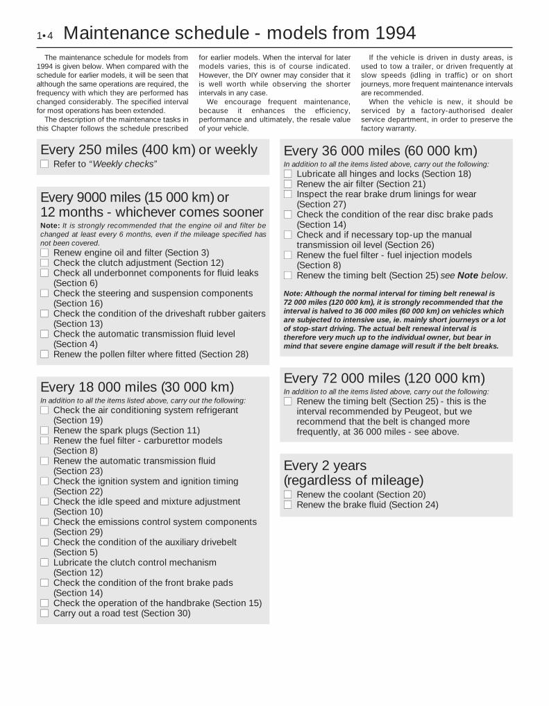
The maintenance schedule for models from1994 is given below. When compared with theschedule for earlier models, it will be seen thatalthough the same operations are required, thefrequency with which they are performed haschanged considerably. The specified intervalfor most operations has been extended.
The description of the maintenance tasks inthis Chapter follows the schedule prescribed
for earlier models. When the interval for latermodels varies, this is of course indicated.However, the DIY owner may consider that itis well worth while observing the shorterintervals in any case.
We encourage frequent maintenance,because it enhances the efficiency,performance and ultimately, the resale valueof your vehicle.
If the vehicle is driven in dusty areas, isused to tow a trailer, or driven frequently atslow speeds (idling in traffic) or on shortjourneys, more frequent maintenance intervalsare recommended.
When the vehicle is new, it should beserviced by a factory-authorised dealerservice department, in order to preserve thefactory warranty.
1•4 Maintenance schedule - models from 1994
Every 250 miles (400 km) or weeklymm Refer to “Weekly checks”
Every 18 000 miles (30 000 km)In addition to all the items listed above, carry out the following:mm Check the air conditioning system refrigerant
(Section 19)mm Renew the spark plugs (Section 11)mm Renew the fuel filter - carburettor models
(Section 8)mm Renew the automatic transmission fluid
(Section 23)mm Check the ignition system and ignition timing
(Section 22)mm Check the idle speed and mixture adjustment
(Section 10)mm Check the emissions control system components
(Section 29)mm Check the condition of the auxiliary drivebelt
(Section 5)mm Lubricate the clutch control mechanism
(Section 12)mm Check the condition of the front brake pads
(Section 14)mm Check the operation of the handbrake (Section 15)mm Carry out a road test (Section 30)
Every 9000 miles (15 000 km) or 12 months - whichever comes soonerNote: It is strongly recommended that the engine oil and filter bechanged at least every 6 months, even if the mileage specified hasnot been covered.mm Renew engine oil and filter (Section 3)mm Check the clutch adjustment (Section 12)mm Check all underbonnet components for fluid leaks
(Section 6)mm Check the steering and suspension components
(Section 16)mm Check the condition of the driveshaft rubber gaiters
(Section 13)mm Check the automatic transmission fluid level
(Section 4)mm Renew the pollen filter where fitted (Section 28)
Every 72 000 miles (120 000 km)In addition to all the items listed above, carry out the following:mm Renew the timing belt (Section 25) - this is the
interval recommended by Peugeot, but werecommend that the belt is changed morefrequently, at 36 000 miles - see above.
Every 2 years (regardless of mileage)mm Renew the coolant (Section 20)mm Renew the brake fluid (Section 24)
Every 36 000 miles (60 000 km)In addition to all the items listed above, carry out the following:mm Lubricate all hinges and locks (Section 18)mm Renew the air filter (Section 21)mm Inspect the rear brake drum linings for wear
(Section 27)mm Check the condition of the rear disc brake pads
(Section 14)mm Check and if necessary top-up the manual
transmission oil level (Section 26)mm Renew the fuel filter - fuel injection models
(Section 8)mm Renew the timing belt (Section 25) see Note below.
Note: Although the normal interval for timing belt renewal is 72 000 miles (120 000 km), it is strongly recommended that theinterval is halved to 36 000 miles (60 000 km) on vehicles whichare subjected to intensive use, ie. mainly short journeys or a lotof stop-start driving. The actual belt renewal interval istherefore very much up to the individual owner, but bear inmind that severe engine damage will result if the belt breaks.
Maintenance & Servicing 1•5
1
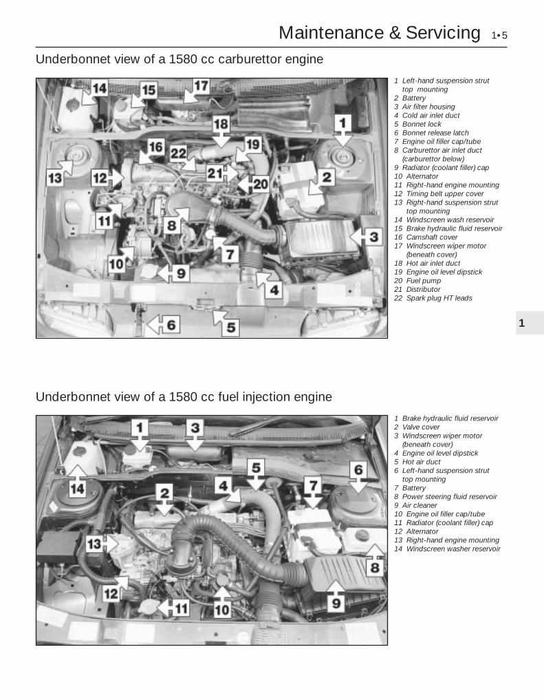
Underbonnet view of a 1580 cc carburettor engine
1 Left-hand suspension strut top mounting
2 Battery3 Air filter housing4 Cold air inlet duct5 Bonnet lock6 Bonnet release latch7 Engine oil filler cap/tube8 Carburettor air inlet duct
(carburettor below)9 Radiator (coolant filler) cap10 Alternator11 Right-hand engine mounting12 Timing belt upper cover13 Right-hand suspension strut
top mounting14 Windscreen wash reservoir15 Brake hydraulic fluid reservoir16 Camshaft cover17 Windscreen wiper motor
(beneath cover)18 Hot air inlet duct19 Engine oil level dipstick20 Fuel pump21 Distributor22 Spark plug HT leads
Underbonnet view of a 1580 cc fuel injection engine
1 Brake hydraulic fluid reservoir2 Valve cover3 Windscreen wiper motor
(beneath cover)4 Engine oil level dipstick5 Hot air duct6 Left-hand suspension strut
top mounting7 Battery8 Power steering fluid reservoir9 Air cleaner10 Engine oil filler cap/tube11 Radiator (coolant filler) cap12 Alternator13 Right-hand engine mounting14 Windscreen washer reservoir
1•6 Maintenance & Servicing
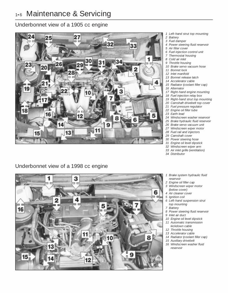
Underbonnet view of a 1998 cc engine
1 Brake system hydraulic fluid reservoir
2 Engine oil filler cap3 Windscreen wiper motor
(below cover)4 Air cleaner cover5 Ignition coil6 Left-hand suspension strut
top mounting7 Battery8 Power steering fluid reservoir9 Inlet air duct10 Engine oil level dipstick11 Automatic transmission
kickdown cable12 Throttle housing13 Accelerator cable14 Radiator (coolant filler cap)15 Auxiliary drivebelt16 Windscreen washer fluid
reservoir
Underbonnet view of a 1905 cc engine
1 Left-hand strut top mounting2 Battery3 Fuel damper4 Power steering fluid reservoir5 Air filter cover6 Fuel injection control unit7 Thermostat housing8 Cold air inlet9 Throttle housing10 Brake servo vacuum hose11 Bonnet lock12 Inlet manifold13 Bonnet release latch14 Accelerator cable15 Radiator (coolant filler cap)16 Alternator17 Right-hand engine mounting18 Fuel injection relay box19 Right-hand strut top mounting20 Camshaft drivebelt top cover21 Fuel pressure regulator22 Engine oil filler tube23 Earth lead24 Windscreen washer reservoir25 Brake hydraulic fluid reservoir26 Brake servo vacuum unit27 Windscreen wiper motor 28 Fuel rail and injectors29 Camshaft cover30 Power steering hose31 Engine oil level dipstick32 Windscreen wiper arm33 Air inlet grille (ventilation)34 Distributor

Maintenance & Servicing 1•7
1
Rear underbody view of a 1905 cc engine model
1 Fuel tank2 Fuel tank supporting strap3 Heat shield4 Exhaust pipe5 Rear suspension side member6 Handbrake cable equaliser
mechanism7 Rear suspension torsion bar8 Rear shock absorber9 Rear disc brake caliper10 Exhaust rear silencer11 Spare wheel (cover removed)12 Spare wheel cradle support
hook13 Fuel filler hose14 Rear anti-roll bar15 Suspension cross-link
Front underbody view of a 1905 cc engine model
1 Fuel lines2 Front exhaust silencer3 Brake lines4 Front subframe rear mounting5 Steering rack mountings6 Exhaust downpipe7 Steering tack rod8 Lower suspension arm9 Radiator lower hose10 Engine oil sump11 Rear engine mounting12 Driveshaft intermediate
bearing housing13 Right-hand driveshaft14 Oil temperature sensor15 Engine oil drain plug16 Radiator17 Transmission housing18 Differential housing19 Cooling fan resistor20 Horn

Maintenance procedures
1•8 6000 Mile / 6 Month Service
1 Introduction
General information1 This Chapter is designed to help the homemechanic maintain his/her vehicle for safety,economy, long life and peak performance.2 The Chapter contains a mastermaintenance schedule, followed by Sectionsdealing specifically with each task in theschedule. Visual checks, adjustments,component renewal and other helpful itemsare included. Refer to the accompanyingillustrations of the engine compartment andthe underside of the vehicle for the locationsof the various components.3 Servicing your vehicle in accordance withthe mileage/time maintenance schedule andthe following Sections will provide a plannedmaintenance programme, which should resultin a long and reliable service life. This is acomprehensive plan, so maintaining someitems but not others at the specified serviceintervals, will not produce the same results.4 As you service your vehicle, you willdiscover that many of the procedures can -and should - be grouped together, because ofthe particular procedure being performed, orbecause of the close proximity of twootherwise-unrelated components to oneanother. For example, if the vehicle is raisedfor any reason, the exhaust can be inspectedat the same time as the suspension andsteering components.5 The first step in this maintenance
programme is to prepare yourself before theactual work begins. Read through all theSections relevant to the work to be carriedout, then make a list and gather together allthe parts and tools required. If a problem isencountered, seek advice from a partsspecialist, or a dealer service department.
2 Intensive maintenance
1 If, from the time the vehicle is new, theroutine maintenance schedule is followedclosely, and frequent checks are made of fluidlevels and high-wear items, as suggestedthroughout this manual, the engine will bekept in relatively good running condition, andthe need for additional work will be minimised.2 It is possible that there will be times whenthe engine is running poorly due to the lack ofregular maintenance. This is even more likelyif a used vehicle, which has not receivedregular and frequent maintenance checks, ispurchased. In such cases, additional workmay need to be carried out, outside of theregular maintenance intervals.3 If engine wear is suspected, a compressiontest will provide valuable informationregarding the overall performance of the maininternal components. Such a test can be usedas a basis to decide on the extent of the workto be carried out. If, for example, acompression test indicates serious internalengine wear, conventional maintenance asdescribed in this Chapter will not greatlyimprove the performance of the engine, and
may prove a waste of time and money, unlessextensive overhaul work is carried out first.4 The following series of operations are thosemost often required to improve theperformance of a generally poor-runningengine:
Primary operationsa) Clean, inspect and test the battery (see
“Weekly checks”).b) Check all the engine-related fluids (see
“Weekly checks”).c) Check the condition and tension of the
auxiliary drivebelt (Section 5).d) Renew the spark plugs (Section 11).e) Inspect the distributor cap and HT leads -
as applicable (Section 22).f) Check the condition of the air cleaner
filter element, and renew if necessary(Section 21).
g) Renew the fuel filter (Section 8).h) Check the condition of all hoses, and
check for fluid leaks (Section 6).i) Check the idle speed and mixture settings
- as applicable (Section 10).
5 If the above operations do not prove fullyeffective, carry out the following secondaryoperations:
Secondary operationsa) Check the charging system (Chapter 5A).b) Check the ignition system (Chapter 5B).c) Check the fuel system (Chapter 4).d) Renew the distributor cap and rotor arm -
as applicable (Chapter 5B).e) Renew the ignition HT leads - as
applicable (Section 22).
6000 Mile / 6 Month Service
3 Engine oil and filter renewal 1Note: On models from 1994, the maker’sspecified interval for this procedure is 9000 miles (15 000 km) or 12 months.Note: A suitable square-section wrench maybe required to undo the sump drain plug onsome models. These wrenches cab beobtained from most motor factors or yourPeugeot dealer.1 Frequent oil and filter changes are the mostimportant preventative maintenanceprocedures which can be undertaken by theDIY owner. As engine oil ages, it becomesdiluted and contaminated, which leads topremature engine wear.2 Before starting this procedure, gathertogether all the necessary tools and materials.
Also make sure that you have plenty of cleanrags and newspapers handy, to mop up anyspills. Ideally, the engine oil should be warm,as it will drain better, and more built-upsludge will be removed with it. Take care,however, not to touch the exhaust or anyother hot parts of the engine when workingunder the vehicle. To avoid any possibility ofscalding, and to protect yourself frompossible skin irritants and other harmfulcontaminants in used engine oils, it isadvisable to wear gloves when carrying outthis work. Access to the underside of thevehicle will be greatly improved if it can beraised on a lift, driven onto ramps, or jackedup and supported on axle stands (see“Jacking and Vehicle Support”). Whichevermethod is chosen, make sure that the vehicleremains level, or if it is at an angle, so that thedrain plug is at the lowest point. Wherenecessary remove the splash guard fromunder the engine.
3 Slacken the drain plug about half a turn; onsome models, a square-section wrench maybe needed to slacken the plug (seeillustration). Position the draining containerunder the drain plug, then remove the plugcompletely. If possible, try to keep the plug
3.3 Slackening the sump drain plug with asquare-section wrench

pressed into the sump while unscrewing it byhand the last couple of turns (see HaynesHint) .4 Recover the sealing ring from the drainplug.5 Allow some time for the old oil to drain,noting that it may be necessary to repositionthe container as the oil flow slows to a trickle.6 After all the oil has drained, wipe off thedrain plug with a clean rag. Check the sealingwasher for condition, and renew it ifnecessary. Clean the area around the drainplug opening, then refit and tighten the plug.7 If the filter is also to be renewed, move thecontainer into position under the oil filterwhich is located on the front side of thecylinder block, below the inlet manifold.8 Using an oil filter removal tool if necessary,slacken the filter initially, then unscrew it byhand the rest of the way (see illustration).Empty the oil from the old filter into thecontainer, and discard the filter.9 Use a clean rag to remove all oil, dirt andsludge from the filter sealing area on theengine. Check the old filter to make sure thatthe rubber sealing ring hasn’t stuck to theengine. If it has, carefully remove it.10 Apply a light coating of clean engine oil tothe sealing ring on the new filter, then screw itinto position on the engine. Tighten the filterfirmly by hand only - do not use any tools.Wipe clean the filter and sump drain plug.
11 Remove the old oil and all tools fromunder the car, then lower the car to theground (if applicable).12 Remove the dipstick then unscrew the oilfiller cap from the cylinder head cover. Fill theengine, using the correct grade and type of oil(see “Weekly checks”). An oil can spout orfunnel may help to reduce spillage. Pour inhalf the specified quantity of oil first, then waita few minutes for the oil to fall to the sump.Continue adding oil a small quantity at a timeuntil the level is up to the lower mark on thedipstick. Finally, bring the level up to theupper mark on the dipstick. Insert thedipstick, and refit the filler cap.13 Start the engine and run it for a fewminutes; check for leaks around the oil filterseal and the sump drain plug. Note that theremay be a delay of a few seconds before the oilpressure warning light goes out when theengine is first started, as the oil circulatesthrough the engine oil galleries and the new oilfilter, before the pressure builds up.14 Switch off the engine, and wait a fewminutes for the oil to settle in the sump oncemore. With the new oil circulated and the filtercompletely full, recheck the level on thedipstick, and add more oil as necessary.15 Dispose of the used engine oil safely, withreference to “General Repair Procedures” inthe Reference section of this manual.
4 Automatic transmission fluidlevel check 1
Note: On models from 1994, the maker’sspecified interval for this procedure is 9000 miles (15 000 km) or 12 months.1 Take the vehicle on a short journey, towarm the transmission up to normal operatingtemperature, then park the vehicle on levelground. The fluid level is checked using thedipstick located at the front of the enginecompartment, directly in front of theengine/transmission. The dipstick top isbrightly-coloured (usually orange) for easyidentification.2 With the engine idling and the selector leverin the “P” (Park) position, withdraw thedipstick from the tube, and wipe all the fluidfrom its end with a clean rag or paper towel.Insert the clean dipstick back into the tube asfar as it will go, then withdraw it once more.Note the fluid level on the end of the dipstick;it should be between the upper and lowermarks (see illustrations).
3 If topping-up is necessary, add the requiredquantity of the specified fluid to thetransmission via the dipstick tube. Use afunnel with a fine mesh gauze, to avoidspillage, and to ensure that no foreign matterenters the transmission. Note: Never overfillthe transmission so that the fluid level is abovethe upper mark.4 After topping-up, take the vehicle on ashort run to distribute the fresh fluid, thenrecheck the level again, topping-up ifnecessary.5 Always maintain the level between the twodipstick marks. If the level is allowed to fallbelow the lower mark, fluid starvation mayresult, which could lead to severetransmission damage.6 Frequent need for topping-up indicates thatthere is a leak, which should be found andcorrected before it becomes serious.
5 Auxiliary drivebelt check and renewal 3
Note: On models from 1994, the maker’sspecified interval for this procedure is 18 000 miles (30 000 km).Note: Peugeot specify the use of a specialelectronic tool (SEEM C.TRONIC type 105 belttensioning measuring tool) to correctly set theauxiliary drivebelt tension. If access to thisequipment cannot be obtained, anapproximate setting can be achieved usingthe method described below. If the methoddescribed is used, the tension should be
6000 Mile / 6 Month Service 1•9
4.2a Withdrawing the automatictransmission dipstick
4.2b Automatic transmission fluid dipsticklower (a) and upper (b) fluid level markings
3.8 Using an oil filter removal tool toslacken the oil filter
1
As the engine oil drain plug releasesfrom the threads, move it away sharplyso the stream of oil issuing from thesump runs into the container, not upyour sleeve!
Note: It isantisocial andillegal to dump oildown the drain.To find thelocation of yourlocal oil recyclingbank, call thisnumber free.

checked using the special electronic tool atthe earliest opportunity.1 Except for XU9J4 16-valve engines, allmodels are fitted with one auxiliary drivebeltdriven from the crankshaft pulley on the right-hand side of the engine. On non-airconditioning models the belt drives thealternator and power steering pump and itstension is adjusted manually. On models fittedwith air conditioning it drives the alternator,power steering pump and the air conditioningcompressor. On XU9J4 models a separatedrivebelt drives the power steering pump froma pulley on the end of the camshaft.
Checking the auxiliary drivebelt condition
Except XU9J4 16-valve power steering drivebelt2 Apply the handbrake, then jack up the frontof the car and support it on axle stands (see“Jacking and Vehicle Support”). Remove theright-hand front roadwheel.3 Remove the engine undercover andwheelarch cover as applicable.4 Using a suitable socket and extension barfitted to the crankshaft sprocket/pulley bolt,rotate the crankshaft so that the entire lengthof the drivebelt can be examined. Examine thedrivebelt for cracks, splitting, fraying ordamage. Check also for signs of glazing (shinypatches) and for separation of the belt plies.Renew the belt if worn or damaged.5 If the condition of the belt is satisfactory, onmodels where the belt is adjusted manually,check the drivebelt tension as describedbelow. On models with an automatic spring-loaded tensioner, there is no need to checkthe drivebelt tension.
XU9J4 16-valve power steering drivebelt6 The power steering drivebelt is positionedon the left-hand end of the cylinder head.Examine the full length of the drivebelt forcracks, splitting, fraying or damage. Ifnecessary turn the engine with a spanner onthe crankshaft pulley or by engaging 4th gearand pushing the car (for safety, the car mustbe on level ground). Check also for signs ofglazing (shiny patches) and for separation ofthe belt plies.7 If the condition of the belt is satisfactory,check the drivebelt tension as described laterin this Section.
Auxiliary drivebelt (early models) - removal,refitting and tensioning
Removal8 Loosen the alternator pivot and link bolts,then unscrew the adjuster bolt to release thedrivebelt tension (see illustration).9 Remove the drivebelt from the alternator,crankshaft and where necessary the powersteering pulleys.
Refitting and tensioning10 Locate the drivebelt on the pulleys makingsure it is correctly engaged with the grooves.11 The belt tension must be adjusted so thatwith moderate thumb pressure applied mid-way along the belt’s longest run, it can bedeflected by approximately 6.0 mm. Turn theadjuster bolt in or out to obtain the correcttension, then tighten the pivot and link bolts(see illustration).
Auxiliary drivebelt (models with a manually-adjusted tensioning pulley) -removal, refitting and tensioning
Removal12 If not already done, proceed as describedin paragraphs 2 and 3.13 Disconnect the battery negative lead.14 Slacken the tensioner pulley bracketadjustment/mounting bolts (one located in themiddle of the pulley and the other locatedbelow on the bracket (see illustration).15 Fully tighten the adjustment bolt to itsstop, then slip the drivebelt from the pulleys(see illustration).
Refitting16 If the belt is being renewed, ensure thatthe correct type is used. Fit the belt aroundthe pulleys, and take up the slack in the beltby tightening the adjuster bolt. Ensure that theribs on the belt are correctly engaged with thegrooves in the pulleys.17 Tension the drivebelt as described in thefollowing paragraphs.
Tensioning18 If not already done, proceed as describedin paragraphs 2 and 3.19 Correct tensioning of the drivebelt willensure that it has a long life. A belt which istoo slack will slip and perhaps squeal.Beware, however, of overtightening, as thiscan cause wear in the alternator bearings.20 The belt should be tensioned so that,under firm thumb pressure, there is approxi-mately 5.0 mm of free movement at the mid-point between the pulleys on the longest beltrun (see the note at the start of this Section).21 To adjust, unscrew the adjustment boltuntil the tension is correct, then rotate thecrankshaft a couple of times, and recheck thetension. Securely tighten the tensioner pulleybracket adjustment/mounting bolts.22 Reconnect the battery negative lead.23 Refit the engine undercover andwheelarch cover. Refit the roadwheel, andlower the vehicle to the ground.
Auxiliary drivebelt (models with an automaticspring-loaded tensioner pulley) -removal, refitting and tensioning
Removal24 If not already done, proceed as describedin paragraphs 2 and 3.25 Disconnect the battery negative lead.26 Using a square drive key in the squarehole in the bottom of the automatic adjusterbracket, turn the bracket anticlockwise torelease the tension on the belt. Hold thebracket in this position by inserting a 4.0 mm
1•10 6000 Mile / 6 Month Service
5.8 Loosening the alternator adjustmentbolts (early models)
5.14 Tensioner pulley bracket lowermounting bolt (arrowed)
5.15 Auxiliary drivebelt tension adjustmentbolt (arrowed)
5.11 Alternator drivebelt deflection (A)

Allen key through the special hole andtightening the peg.27 Unscrew the mounting bolts and removethe tensioner roller, then slip the auxiliarydrivebelt from the pulleys.28 Check that the tensioner pulleys turnfreely without any sign of roughness.
Refitting and tensioning29 If the belt is being renewed, ensure thatthe correct type is used. Fit the belt aroundthe pulleys making sure that it is engaged withthe correct grooves in the pulleys.30 Refit the tensioner roller and tighten themounting bolts.31 Using the square drive key hold theautomatic adjuster, then release the peg andslowly allow the tensioner to tighten the belt.Check again that the belt is correctly locatedin the pulley grooves.32 Reconnect the battery negative lead.33 Refit the engine undercover andwheelarch cover. Refit the roadwheel, andlower the vehicle to the ground.
Power steering pump drivebelt(XU9J4 16-valve) modelsRemoval34 Drain the hydraulic fluid from the systemas described in Chapter 10.35 Loosen the pump mounting bolts andremove the drivebelt.36 Disconnect the high and low pressureunions on the pump.
37 Remove the bolts and lift off the pump.
Refitting and tensioning38 Refit in reverse order, then tension thebelt by applying a torque of 55 Nm for a newbelt and 30 Nm for a used belt by using thesquare of a torque wrench in the square cut-out in the pump bracket, tightening themounting bolts while the torque tension ismaintained (see illustration).39 Fill and bleed the system (see Chapter 10).
6 Hose and fluid leak check 1Note: On models from 1994, the maker’sspecified interval for this procedure is9000 miles (15 000 km) or 12 months.1 Visually inspect the engine joint faces,gaskets and seals for any signs of water, oil orfuel leaks. Pay particular attention to the areasaround the camshaft cover, cylinder head, oilfilter and sump joint faces. Bear in mind that,over a period of time, some slight seepagefrom these areas is to be expected. What youare really looking for is any indication of aserious leak. Should a leak be found, renewthe offending gasket or oil seal by referring tothe appropriate Chapters in this manual.2 Also check the security and condition of allthe engine-related pipes and hoses. Ensurethat all cable-ties or securing clips are in placeand in good condition. Clips which are brokenor missing can lead to chafing of the hoses,pipes, or wiring, which could cause moreserious problems in the future.3 Carefully check the radiator hoses andheater hoses along their entire length. Renewany hose which is cracked, swollen, ordeteriorated. Cracks will show up better if thehose is squeezed. Pay close attention to thehose clips that secure the hoses to thecooling system components. Hose clips canpinch and puncture hoses, resulting in coolingsystem leaks. If the original Peugeot crimped-type hose clips are used, it may be a goodidea to replace them with standard worm-drive hose clips.
4 Inspect the cooling system (hoses, jointfaces, etc.) for leaks (see Haynes Hint).5 Where any problems of this nature arefound on system components, renew thecomponent or gasket, referring to Chapter 3.6 Where applicable, inspect the automatictransmission fluid cooler hoses for leaks ordeterioration.7 With the vehicle raised, inspect the petroltank and filler neck for punctures, cracks, andother damage. The connection between thefiller neck and tank is especially critical.Sometimes, a rubber filler neck or connectinghose will leak due to loose retaining clamps ordeteriorated rubber.8 Carefully check all rubber hoses and metalfuel lines leading away from the petrol tank.Check for loose connections, deterioratedhoses, crimped lines, and other damage. Payparticular attention to the vent pipes andhoses, which often loop up around the fillerneck, and can become blocked or crimped.Follow the lines to the front of the vehicle,carefully inspecting them all the way. Renewdamaged sections as necessary.9 From within the engine compartment,check the security of all fuel hose attachmentsand pipe unions, and inspect the fuel hosesand vacuum hoses for kinks, chafing anddeterioration.10 Where applicable, check the condition ofthe power steering fluid hoses and pipes.
6000 Mile / 6 Month Service 1•11
1
5.38 Square cut-out in power steeringpump bracket (a) on XU9J4 16-valve models A leak in the cooling system will usually
show up as white or rust coloureddeposits on the area adjoining the leak
12 000 Mile / 12 Month Service
7 Engine breather hose check 1Check the condition and security of all
engine breather hoses.Where the engine has covered a high
mileage, remove the hoses and clean anysludge from them.
8 Fuel filter renewal 2Note: On models from 1994, the maker’sspecified interval for this procedure is 18 000miles (30 000 km) for carburettor models, and36 000 miles (60 000 km) for fuel injectionmodels.
Carburettor models1 The fuel filter is connected into the fuelhose between the pump and the carburettorin the engine compartment (see illustration).2 To remove the filter, release the retainingclips and disconnect the fuel hoses from thefilter. Where the original Peugeot crimped-
Warning: Before carrying outthe following operation, refer tothe precautions in “Safety first!”and follow them implicitly.
Petrol is a highly-dangerous and volatileliquid, and the precautions necessarywhen handling it cannot be overstressed.

type hose clips are fitted, cut them off anddiscard them; use standard worm-drive hoseclips on refitting.3 Note the direction of the arrow marked onthe filter body. Unclip the filter from itsretaining bracket, and remove it from thevehicle.4 Connect the fuel hoses to the new filter.Make sure that the arrow on the filter body ispointing in the direction of the fuel flow, ie.towards the fuel pump. Secure the hoses inposition by securely tightening the retainingclips, then clip the filter back into position inits retaining bracket.5 At the same time, check the fuel reservoirtank on the side of the carburettor for sediment.Remove the reservoir as necessary for cleaning.6 The fuel connections on the reservoir are asfollows.a) Top hose - return to tank.b) Middle hose - supply from pump via filter.c) Lower hose - to carburettor inlet.
Fuel injection models7 The fuel filter is situated underneath the rearof the vehicle, mounted on the right-hand sideof the fuel tank. To gain access to the filter,chock the front wheels, then jack up the rearof the vehicle and support it on axle stands(see “Jacking and Vehicle Support”).8 Clamp the fuel hose on the tank side of thefilter. Bearing in mind the information given inthe relevant Part of Chapter 4 on depres-surising the fuel system, release the clips anddisconnect the fuel hoses from the filter. Beprepared for fuel spillage (see illustration).9 Note the direction of the arrow marked onthe filter body. Slacken the retaining clampscrew, then slide the filter out of the clamp,and remove it from underneath the vehicle.10 Dispose safely of the old filter; it will behighly-inflammable, and may explode ifthrown on a fire.11 Slide the new filter into position in theclamp, ensuring that the arrow on the filterbody is pointing in the direction of the fuelflow, ie. towards the throttle body/fuel rail.This can be determined by tracing the fuelhoses back along their length.12 Connect the fuel hoses to the filter, andsecure them in position with their retainingclips. Remove the hose clamp.
13 Start the engine, and check the filter hoseconnections for leaks. Lower the vehicle tothe ground on completion.
9 Accelerator cable check and adjustment 1
Refer to Chapter 4A or 4B.
10 Idle speed and mixturecheck and adjustment 3
Note: On models from 1994, the maker’sspecified interval for this procedure is 18 000 miles (30 000 km).1 Before checking the idle speed and mixturesetting, always check the following first:a) Check that (where adjustable) the ignition
timing is accurate (Chapter 5B).b) Check that the spark plugs are in good
condition and correctly gapped (Section 11).c) Check that the accelerator cable (and on
carburettor models, the choke cable) iscorrectly adjusted (refer to the relevantPart of Chapter 4).
d) Check that the crankcase breather hosesare secure, with no leaks or kinks(Sections 7 and 29).
e) Check that the air cleaner filter element isclean (Section 21).
f) Check that the exhaust system is in goodcondition (refer to the relevant Part ofChapter 4).
g) If the engine is running roughly, check thecompression pressures and valveclearances as described in Chapter 2.
h) On fuel injection models, check that thefuel injection/ignition system warning lightis not illuminated (refer to the relevantPart of Chapter 4).
2 Take the car on a journey of sufficientlength to warm it up to normal operatingtemperature. Note: Adjustment should ideallybe completed within two minutes of return,without stopping the engine. If the radiatorelectric cooling fan operates, wait for thecooling fan to stop. If adjustment takes longerthan stated, regularly clear any excess fuelfrom the inlet manifold by revving the enginetwo or three times to about 2000 rpm, thenallow it to idle again.
Carburettor models3 Ensure that all electrical loads are switchedoff, and that the choke lever is pushed fully in.If the car does not have a tachometer, connectone following its manufacturer’s instructions.Note the idle speed, and compare it with thatspecified. Note: Models with air conditioninghave an idle compensation device, and the airconditioning compressor must be runningwhile the idle speed is being checked andadjusted.4 Using a suitable flat-bladed screwdriver,screw in the idle adjusting screw (to increasethe speed) or out as necessary to obtain thespecified speed. The screw is located on thecarburettor on non-air conditioning models,and on the idle compensating device on airconditioning models (see illustrations).5 The idle mixture (exhaust gas CO level) isset at the factory, and should require nofurther adjustment. If, due to a change inengine characteristics (carbon build-up, borewear etc) or after a major carburettoroverhaul, the mixture becomes incorrect, itcan be reset. Note, however, that an exhaustgas analyser (CO meter) will be required tocheck the mixture, and to set it with thenecessary standard of accuracy. If this is notavailable, the car must be taken to a Peugeotdealer for the work to be carried out.6 Follow the exhaust gas analysermanufacturer’s instructions to check theexhaust gas CO level. If adjustment isrequired, it is made via mixture adjustment
1•12 12 000 Mile / 12 Month Service
8.1 Fuel filter location on carburettor models
10.4a Idle speed adjustment screw(arrowed) on models with idle compensation
10.4b Idle speed adjustment screw
8.8 Fuel filter on fuel injection modelsshowing fuel hoses (A) and clamp bolt (B)

screw located on the carburettor. The screwis covered with a tamperproof plug to preventunnecessary adjustment. To gain access tothe screw, use a sharp instrument to hook outthe plug.7 Using a suitable flat-bladed screwdriver,turn the mixture adjustment screw by verysmall amounts until the level is correct (seeillustration). Screwing it in (clockwise)weakens the idle mixture and reduces the COlevel; screwing it out will richen the mixtureand increase the CO level.8 When adjustments are complete, disconnectany test equipment, and fit a new tamperproofplug to the mixture adjustment screw. Recheckthe idle speed and, if necessary, readjust.
Fuel injection models
Bosch L3.1-Jetronic system9 Ensure that all electrical loads are switchedoff. If the car does not have a tachometer,connect one following its manufacturer’sinstructions. Note the idle speed, andcompare it with that specified.10 The idle speed is adjusted using the idlespeed adjustment screw on the throttlehousing (see illustration). Turn the screwclockwise to decrease the idle speed, or anti-clockwise to increase the speed.11 The idle mixture (exhaust gas CO level) isset at the factory, and should require nofurther adjustment. If, due to a change inengine characteristics (carbon build-up, borewear etc) or after a major overhaul, themixture becomes incorrect, it can be reset.Note, however, that an exhaust gas analyser
(CO meter) will be required to check themixture, and to set it with the necessarystandard of accuracy. If this is not available,the car must be taken to a Peugeot dealer forthe work to be carried out.12 Follow the exhaust gas analysermanufacturer’s instructions to check theexhaust gas CO level. If adjustment isrequired, it is made via mixture adjustmentscrew located on the airflow meter (seeChapter 4C). The screw may be covered witha tamperproof plug to prevent unnecessaryadjustment. To gain access to the screw, usea sharp instrument to hook out the plug.13 Using a flat-bladed screwdriver, turn themixture adjustment screw by small amountsuntil the level is correct (see illustration).14 When adjustments are complete, disconnectany test equipment, and fit a new tamperproofplug to the mixture adjustment screw. Recheckthe idle speed and, if necessary, readjust.
Bosch ML4.1 Motronic system15 The idle speed is non-adjustable. It iscontrolled by the idle speed regulator valve.16 The idle mixture (exhaust gas CO level) isset at the factory, and should require nofurther adjustment. If, due to a change inengine characteristics (carbon build-up, borewear etc) or after a major overhaul, themixture becomes incorrect, it can be reset.Note, however, that an exhaust gas analyser(CO meter) will be required to check themixture, and to set it with the necessarystandard of accuracy. If this is not available,the car must be taken to a Peugeot dealer forthe work to be carried out.
17 Follow the exhaust gas analysermanufacturer’s instructions to check theexhaust gas CO level. If adjustment isrequired, it is made via mixture adjustmentscrew located on the airflow meter (seeillustration). The screw may be covered witha tamperproof plug to prevent unnecessaryadjustment. To gain access to the screw, usea sharp instrument to hook out the plug.18 Turn the screw clockwise to increase andanti-clockwise to decrease CO content untilthe specified CO level is obtained.19 When adjustments are complete,disconnect any test equipment, and fit a newtamperproof plug to the mixture adjustmentscrew.
Bosch LU2-Jetronic system20 The idle mixture is not adjustable and isautomatically regulated by the ECU.21 To check the idle speed connect atachometer to the engine, then run the engineat idle speed.22 Turn the idle speed adjustment screw toobtain the specified idle speed (seeillustration).23 When adjustments are complete,disconnect any test gear from the engine.
Bosch Motronic MP3.1 system24 Ensure that all electrical loads areswitched off. If the car does not have atachometer, connect one following itsmanufacturer’s instructions. Note the idlespeed, and compare it with that specified.25 Turn the idle speed adjustment screw toobtain the specified idle speed (seeillustration).
12 000 Mile / 12 Month Service 1•13
10.13 Mixture (CO) adjustment screw onthe Bosch L3.1 injection control unit
10.25 Idle speed adjustment screw (1) onthe Bosch Motronic MP3.1 system
10.22 Idle speed adjustment screw (2) onthe Bosch LU2-Jetronic injection system
10.17 Mixture (CO) adjustment screw(arrowed) on Bosch ML4.1 Motronic system
10.10 Adjusting the idle speed screw onthe Bosch L3.1 injection system
1
10.7 Idle mixture adjustment screw(arrowed)

26 The idle mixture (exhaust gas CO level) isset at the factory, and should require nofurther adjustment. If, due to a change inengine characteristics (carbon build-up, borewear etc) or after a major overhaul, themixture becomes incorrect, it can be reset.Note, however, that an exhaust gas analyser(CO meter) will be required to check themixture, and to set it with the necessarystandard of accuracy. If this is not available,the car must be taken to a Peugeot dealer forthe work to be carried out.27 Follow the exhaust gas analysermanufacturer’s instructions to check theexhaust gas CO level. If adjustment isrequired, it is made via mixture adjustmentscrew (see illustration). The screw may becovered with a tamperproof plug to preventunnecessary adjustment. To gain access tothe screw, use a sharp instrument to hook outthe plug.28 Turn the screw clockwise to increase andanti-clockwise to decrease CO content untilthe specified CO level is obtained.29 When adjustments are complete,disconnect any test equipment, and fit a newtamperproof plug to the mixture adjustmentscrew.
Bosch Motronic M1.3 fuel injectionsystem30 The idle speed is only adjustable on theXU9JA/Z engine - on other engines it iscontrolled by the ECU and idle speed controlvalve.31 Ensure that all electrical loads areswitched off. If the car does not have atachometer, connect one following itsmanufacturer’s instructions. Note the idlespeed, and compare it with that specified.32 Turn the idle speed adjustment screw toobtain the specified idle speed (seeillustration).33 The idle mixture (CO) is only adjustable onthe XU9J4/K engine - on other engines it iscontrolled by the ECU.34 The idle mixture (exhaust gas CO level) isset at the factory, and should require nofurther adjustment. If, due to a change inengine characteristics (carbon build-up, borewear etc) or after a major overhaul, themixture becomes incorrect, it can be reset.Note, however, that an exhaust gas analyser
(CO meter) will be required to check themixture, and to set it with the necessarystandard of accuracy. If this is not available,the car must be taken to a Peugeot dealer forthe work to be carried out.35 Follow the exhaust gas analysermanufacturer’s instructions to check theexhaust gas CO level. If adjustment isrequired, it is made via mixture adjustmentscrew located on top of the airflow meterassembly (see illustration). The screw maybe covered with a tamperproof plug toprevent unnecessary adjustment. To gainaccess to the screw, use a sharp instrumentto hook out the plug.36 Turn the screw clockwise to increase andanti-clockwise to decrease CO content untilthe specified CO level is obtained.
All other fuel injection systems37 Experienced home mechanics, with aconsiderable amount of skill and equipment(including a tachometer and an accurateexhaust gas analyser) may be able to checkthe exhaust CO level and the idle speed.However, if these are found to be in need ofadjustment, the car must be taken to asuitably-equipped Peugeot dealer.38 On models with a Magneti Marelli enginemanagement (fuel injection/ignition) system,adjustment of the mixture setting (exhaust gasCO level) is possible, but adjustments canonly be made by reprogramming the enginemanagement ECU using special electronictest equipment which is connected to thediagnostic connector (see Chapter 4).39 On all other vehicles, adjustments are notpossible. If the idle speed or the exhaust gasCO level is incorrect, there must be a fault inthe engine management system, and thevehicle should be taken to a Peugeot dealerfor testing (see Chapter 4).
11 Spark plug renewal 2Note: On models from 1994, the maker’sspecified interval for this procedure is 18 000 miles (30 000 km).1 The correct functioning of the spark plugs isvital for the correct running and efficiency of
the engine. It is essential that the plugs fittedare appropriate for the engine (the suitabletype is specified at the beginning of thisChapter). If this type is used, and the engine isin good condition, the spark plugs should notneed attention between scheduledreplacement intervals. Spark plug cleaning israrely necessary, and should not beattempted unless specialised equipment isavailable, as damage can easily be caused tothe firing ends.2 On 16-valve models, to gain access to thespark plugs, the access cover fitted over thecentre of the cylinder head must first beremoved. Undo the eight bolts, noting theposition of the wiring retaining clip, andremove the cover (see illustration).3 On other models, to improve access tosome of the plugs, it may be necessary toremove the air inlet duct (refer to Chapter 4 forfurther information).4 On 1998 cc 16-valve models, pull the HTcoils off the spark plugs. If necessary, toremove the possibility of the HT coils beingconnected to the wrong spark plugs onrefitting, mark the coils 1 to 4 (No 1 cylinder isat the transmission end of the engine).5 On all other models, if the marks on theoriginal-equipment spark plug (HT) leadscannot be seen, mark the leads 1 to 4,corresponding to the cylinder the lead serves(No 1 cylinder is at the transmission end of theengine). Pull the leads from the plugs bygripping the end fitting, not the lead,otherwise the lead connection may befractured (see illustration).
1•14 12 000 Mile / 12 Month Service
10.27 Mixture (CO) adjustment screw (2)on the Bosch MP3.1 fuel injection system
10.35 Mixture adjustment screw (5) on theBosch Motronic M1.3 fuel injection system
11.2 On 16-valve models undo the eightbolts (arrowed) and remove the access
cover to reach the spark plugs
10.32 Idle speed adjustment screw (7) onthe Bosch Motronic M1.3 injection system

6 It is advisable to remove the dirt from thespark plug recesses, using a clean brush,vacuum cleaner or compressed air beforeremoving the plugs, to prevent dirt droppinginto the cylinders.7 Unscrew the plugs using a spark plugspanner, suitable box spanner, or a deepsocket and extension bar (see illustration).Keep the socket aligned with the spark plug -if it is forcibly moved to one side, the ceramicinsulator may be broken off. As each plug isremoved, examine it as follows.8 Examination of the spark plugs will give agood indication of the condition of the engine.If the insulator nose of the spark plug is cleanand white, with no deposits, this is indicativeof a weak mixture or too hot a plug (a hot plugtransfers heat away from the electrode slowly,a cold plug transfers heat away quickly).9 If the tip and insulator nose are coveredwith hard black-looking deposits, then this isindicative that the mixture is too rich. Shouldthe plug be black and oily, then it is likely thatthe engine is fairly worn, as well as the mixturebeing too rich.
10 If the insulator nose is covered with lighttan to greyish-brown deposits, then themixture is correct, and it is likely that theengine is in good condition.11 The spark plug electrode gap is ofconsiderable importance as, if it is too large ortoo small, the size of the spark and itsefficiency will be seriously impaired. The gapshould be set to the value given in the Specifi-cations at the beginning of this Chapter.12 To set the gap, measure it with a feelerblade, then bend the outer plug electrode untilthe correct gap is achieved (see illustration).The centre electrode should never be bent, asthis may crack the insulator and cause plugfailure, if nothing worse. If using feeler blades,the gap is correct when the appropriate-sizeblade is a firm, sliding fit.13 Special spark plug electrode gapadjusting tools are available from most motoraccessory shops, or from some spark plugmanufacturers.14 Before fitting the spark plugs, check thatthe threaded connector sleeves (on top of theplug) are tight, and that the plug exteriorsurfaces and threads are clean. It is very oftendifficult to insert spark plugs into their holeswithout cross-threading them. To avoid thispossibility, fit a short length of hose over theend of the spark plug (see Haynes Hint).15 Remove the rubber hose (if used), andtighten the plug to the specified torque (see“Specifications”) using the spark plug socketand a torque wrench. Refit the remainingplugs in the same way.16 Connect the HT leads in the correct order,and refit any components removed foraccess. On 1998 cc 16-valve models, connectthe HT coils in their correct order.
12 Clutch adjustment checkand control mechanismlubrication 2
Note: On models from 1994, the maker’sspecified interval for this procedure is 9000 miles (15 000 km) or 12 months for clutchadjustment, and 18 000 miles (30 000 km) forlubrication.1 Check that the clutch pedal movessmoothly and easily through its full travel.
2 The clutch itself should function correctly,with no trace of slip or drag.3 Where possible, adjust the clutch cable ifnecessary, as described in Chapter 6.4 If excessive effort is required to operate theclutch, check first that the cable is correctlyrouted and undamaged. Remove the pedal,and make sure that its pivot is properlygreased. Refer to Chapter 6 for furtherinformation.
13 Driveshaft gaiter check 1Note: On models from 1994, the maker’sspecified interval for this procedure is 9000 miles (15 000 km) or 12 months.
With the vehicle raised and securelysupported on stands, turn the steering ontofull lock, then slowly rotate the roadwheel.Inspect the condition of the outer constantvelocity (CV) joint rubber gaiters, whilesqueezing the gaiters to open out the folds(see illustration). Check for signs of cracking,splits, or deterioration of the rubber, whichmay allow the grease to escape, and lead towater and grit entry into the joint. Also checkthe security and condition of the retainingclips. Repeat these checks on the inner CVjoints. If any damage or deterioration is found,the gaiters should be renewed without delayas described in Chapter 8.
At the same time, check the generalcondition of the CV joints themselves, by firstholding the driveshaft and attempting to rotate
12 000 Mile / 12 Month Service 1•15
13.1 Check the condition of the driveshaftgaiters (arrowed)
11.12 Measuring the spark plug gap with afeeler blade
11.7 Tools required for spark plugremoval, gap adjustment and refitting
11.5 Pulling the HT leads from the spark plugs
1
It is often difficult to insert spark plugsinto their holes without cross-threadingthem. To avoid this possibility, fit ashort length of 5/16 inch internaldiameter rubber hose over the end ofthe spark plug. The flexible hose acts asa universal joint to help align the plugwith the plug hole. Should the plugbegin to cross-thread, the hose will slipon the spark plug, preventing threaddamage to the cylinder head.

the wheel. Repeat this check by holding theinner joint and attempting to rotate thedriveshaft. Any obvious movement indicateswear in the joints, wear in the driveshaft splines,or a loose driveshaft retaining nut.
14 Front and rear disc pad check 1
Note: On models from 1994, the maker’sspecified interval for this procedure is 18 000 miles (30 000 km) for the front brakepads, and 36 000 miles (60 000 km) for therear brake pads or shoes.1 Firmly apply the handbrake, then jack upthe front or rear of the car (as applicable) andsupport it securely on axle stands (see“Jacking and Vehicle Support”). Remove thefront or rear roadwheels.
2 If any pad’s friction material is worn to thespecified thickness or less, all four pads mustbe renewed as a set.3 For a comprehensive check, the brake padsshould be removed and cleaned. Theoperation of the caliper can then also bechecked, and the condition of the brake discitself can be fully examined on both sides.Refer to Chapter 9 for further information.
15 Handbrake check andadjustment 3
Note: On models from 1994, the maker’sspecified interval for this procedure is 9000 miles (15 000 km) or 12 months.
Refer to Chapter 9.
16 Steering and suspension check 2
Note: On models from 1994, the maker’sspecified interval for this procedure is 9000 miles (15 000 km) or 12 months.
Front suspension and steering check1 Raise the front of the car, and support on axlestands (see “Jacking and Vehicle Support”).
2 Inspect the balljoint dust covers and thesteering rack-and-pinion gaiters for splits,chafing or deterioration. Any wear of thesecomponents will cause loss of lubricant, withdirt and water entry, resulting in rapiddeterioration of the balljoints or steering gear.3 On vehicles with power steering, check thefluid hoses for chafing or deterioration, andthe pipe and hose unions for fluid leaks. Alsocheck for signs of fluid leakage underpressure from the steering gear rubbergaiters, which would indicate failed fluid sealswithin the steering gear.4 Grasp the roadwheel at the 12 o’clock and 6 o’clock positions, and try to rock it (seeillustration). Very slight free play may be felt,but if the movement is appreciable, furtherinvestigation is necessary to determine thesource. Continue rocking the wheel while anassistant depresses the footbrake. If themovement is now eliminated or significantlyreduced, it is likely that the hub bearings areat fault. If the free play is still evident with thefootbrake depressed, then there is wear in thesuspension joints or mountings.5 Now grasp the wheel at the 9 o’clock and 3 o’clock positions, and try to rock it asbefore. Any movement felt now may again becaused by wear in the hub bearings or thesteering track-rod balljoints. If the outerballjoint is worn, the visual movement will beobvious. If the inner joint is suspect, it can befelt by placing a hand over the rack-and-pinionrubber gaiter and gripping the track-rod. If thewheel is now rocked, movement will be felt atthe inner joint if wear has taken place.6 Using a large screwdriver or flat bar, checkfor wear in the suspension mounting bushesby levering between the relevant suspensioncomponent and its attachment point. Somemovement is to be expected, as themountings are made of rubber, but excessivewear should be obvious. Also check thecondition of any visible rubber bushes,looking for splits, cracks or contamination ofthe rubber.7 With the car standing on its wheels, have anassistant turn the steering wheel back andforth, about an eighth of a turn each way.There should be very little, if any, lostmovement between the steering wheel androadwheels. If this is not the case, closelyobserve the joints and mountings previouslydescribed. In addition, check the steeringcolumn universal joints for wear, and alsocheck the rack-and-pinion steering gear itself.
Rear suspension check8 Chock the front wheels, then jack up therear of the car and support on axle stands(see “Jacking and Vehicle Support”).
9 Working as described previously for thefront suspension, check the rear hubbearings, the suspension bushes and theshock absorber mountings for wear.
Suspension strut/shock absorber check10 Check for any signs of fluid leakagearound the suspension strut/shock absorberbody, or from the rubber gaiter around thepiston rod. Should any fluid be noticed, thesuspension strut/shock absorber is defectiveinternally, and should be renewed. Note:Suspension struts/shock absorbers shouldalways be renewed in pairs on the same axle.11 The efficiency of the suspensionstrut/shock absorber may be checked bybouncing the vehicle at each corner.Generally speaking, the body will return to itsnormal position and stop after beingdepressed. If it rises and returns on arebound, the suspension strut/shockabsorber is probably suspect. Examine alsothe suspension strut/shock absorber upperand lower mountings for any signs of wear.
17 Body drain channel check 1Check and unblock all door and sill drain
channels. Also check the heater drain tubelocated at the rear of the enginecompartment.
1•16 12 000 Mile / 12 Month Service
16.4 Check for wear in the hub bearingsby grasping the wheel and trying to rock it
For a quick check, thethickness of friction materialremaining on each brake padcan be measured through
the aperture in the caliper body.

20 Coolant renewal 2Note: On models from 1994, the maker’sspecified interval for this procedure is every 2 years, regardless of mileage.
Cooling system draining
1 With the engine completely cold, removethe expansion tank filler cap. Turn the capanti-clockwise until it reaches the first stop.Wait until any pressure remaining in the
system is released, then push the cap down,turn it anti-clockwise to the second stop, andlift it off.2 Position a suitable container beneath thecoolant drain outlet at the lower left-hand sideof the radiator.3 Loosen the drain plug (there is no need toremove it completely) and allow the coolant todrain into the container. If desired, a length oftubing can be fitted to the drain outlet todirect the flow of coolant during draining (seeillustration).
4 To assist draining, open the cooling systembleed screws. On all except 1.4 litre engines,the bleed screws are located in the thermostatcover and thermostat housing. On 1.4 litreengines, the bleed screws are located in thethermostat housing, and in the cylinder headcoolant bypass hose. Additionally, on 2.0 litreXU10J4 engines, there is a bleed screwlocated in the coolant bypass hose behind thecylinder head. All models also have a bleedscrew located at the top left-hand corner ofthe radiator (see illustrations).
18 Hinge and lock lubrication 1Note: On models from 1994, the maker’sspecified interval for this procedure is 36 000 miles (60 000 km).1 Work around the vehicle, and lubricate thehinges of the bonnet, doors and tailgate with alight machine oil.2 Lightly lubricate the bonnet releasemechanism and exposed section of innercable with a smear of grease.3 Check carefully the security and operationof all hinges, latches and locks, adjustingthem where required. Check the operation ofthe central locking system (if fitted).4 Check the condition and operation of thetailgate struts, renewing them if either isleaking or is no longer able to support thetailgate securely when raised.
19 Air conditioning refrigerantcheck 1
Note: On models from 1994, the maker’sspecified interval for this procedure is 18 000 miles (30 000 km).
1 In order to check the condition of therefrigerant, a humidity indicator and a sightglass are provided on top of the drier bottle,located in the front, left-hand corner of theengine compartment (see illustration).
Refrigerant humidity check2 Check the colour of the humidity indicator.Blue indicates that the condition of therefrigerant is satisfactory. Pink indicates that
the refrigerant is saturated with humidity. Ifthe indicator shows red, the system should bedrained and recharged, and a new drier bottleshould be fitted. Note: The system should bedrained and recharged only by a Peugeotdealer or air conditioning specialist. Do notattempt to carry out the work yourself, as therefrigerant is a highly-dangerous substance(refer to Chapter 3).
Refrigerant flow check3 Run the engine, and switch on the airconditioning.4 After a few minutes, inspect the sight glass,and check the fluid flow. Clear fluid should bevisible - if not, the following will help todiagnose the problem:
a) Clear fluid flow - the system is functioningcorrectly.
b) No fluid flow - have the system checkedfor leaks by a Peugeot dealer or airconditioning specialist.
c) Continuous stream of clear air bubbles influid - refrigerant level low - have thesystem recharged by a Peugeot dealer orair conditioning specialist.
d) Milky air bubbles visible - high humidity(see paragraph 2).
18 000 Mile / 18 Month Service
18 000 Mile / 18 Month Service 1•17
20.4a Cooling system bleed screws onthermostat housing and cover (arrowed) -
1.6 litre engine shown
19.1 Air conditioning system drier bottlesight glass (1) and humidity indicator (2)
20.3 Radiator drain outlet (arrowed)
1
Warning: Do not attempt toopen the refrigerant circuit.Refer to the precautions givenin Chapter 3.
24 000 Mile / 2 Year Service
Warning: Wait until the engine iscold before starting thisprocedure. Do not allowantifreeze to come in contact
with your skin, or with the paintedsurfaces of the vehicle. Rinse off spillsimmediately with plenty of water. Neverleave antifreeze lying around in an opencontainer, or in a puddle in the drivewayor on the garage floor. Children and petsare attracted by its sweet smell, butantifreeze can be fatal if ingested.
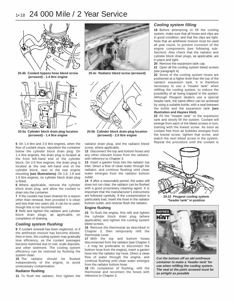
5 On 1.4 litre and 2.0 litre engines, when theflow of coolant stops, reposition the containerbelow the cylinder block drain plug. On 1.4 litre engines, the drain plug is located atthe front left-hand end of the cylinder block. On 2.0 litre engines, the drain plug islocated at the rear left-hand end of thecylinder block, next to the rear enginemounting (see illustrations). On 1.6, 1.8 and1.9 litre engines, no cylinder block drain plugis fitted.6 Where applicable, remove the cylinderblock drain plug, and allow the coolant todrain into the container.7 If the coolant has been drained for a reasonother than renewal, then provided it is cleanand less than two years old, it can be re-used,though this is not recommended.8 Refit and tighten the radiator and cylinderblock drain plugs, as applicable, oncompletion of draining.
Cooling system flushing9 If coolant renewal has been neglected, or ifthe antifreeze mixture has become diluted,then in time, the cooling system may graduallylose efficiency, as the coolant passagesbecome restricted due to rust, scale deposits,and other sediment. The cooling systemefficiency can be restored by flushing thesystem clean.10 The radiator should be flushedindependently of the engine, to avoidunnecessary contamination.
Radiator flushing11 To flush the radiator, first tighten the
radiator drain plug, and the radiator bleedscrew, where applicable.12 Disconnect the top and bottom hoses andany other relevant hoses from the radiator,with reference to Chapter 3.13 Insert a garden hose into the radiator topinlet. Direct a flow of clean water through theradiator, and continue flushing until cleanwater emerges from the radiator bottomoutlet.14 If after a reasonable period, the water stilldoes not run clear, the radiator can be flushedwith a good proprietary cleaning agent. It isimportant that the manufacturer’s instructionsare followed carefully. If the contamination isparticularly bad, insert the hose in the radiatorbottom outlet, and reverse-flush the radiator.
Engine flushing15 To flush the engine, first refit and tightenthe cylinder block drain plug (whereapplicable), and tighten the cooling systembleed screws.16 Remove the thermostat as described inChapter 3, then temporarily refit thethermostat cover.17 With the top and bottom hosesdisconnected from the radiator (see Chapter 3- it may be preferable to disconnect thebottom hose from the engine), insert a gardenhose into the radiator top hose. Direct a cleanflow of water through the engine, andcontinue flushing until clean water emergesfrom the radiator bottom hose.18 On completion of flushing, refit thethermostat and reconnect the hoses withreference to Chapter 3.
Cooling system filling19 Before attempting to fill the coolingsystem, make sure that all hoses and clips arein good condition, and that the clips are tight.Note that an antifreeze mixture must be usedall year round, to prevent corrosion of theengine components (see following sub-Section). Also check that the radiator andcylinder block drain plugs, as applicable, arein place and tight.20 Remove the expansion tank cap.21 Open all the cooling system bleed screws(see paragraph 4).22 Some of the cooling system hoses arepositioned at a higher level than the top of theradiator expansion tank. It is thereforenecessary to use a “header tank” whenrefilling the cooling system, to reduce thepossibility of air being trapped in the system.Although Peugeot dealers use a specialheader tank, the same effect can be achievedby using a suitable bottle, with a seal betweenthe bottle and the expansion tank (seeillustration and Haynes Hint).23 Fit the “header tank” to the expansiontank and slowly fill the system. Coolant willemerge from each of the bleed screws in turn,starting with the lowest screw. As soon ascoolant free from air bubbles emerges fromthe lowest screw, tighten that screw, andwatch the next bleed screw in the system.Repeat the procedure until the coolant is
1•18 24 000 Mile / 2 Year Service
20.4b Coolant bypass hose bleed screw(arrowed) - 1.4 litre engine
20.5a Cylinder block drain plug location(arrowed) - 1.4 litre engine
20.22 Peugeot cooling system “header tank” in position
20.5b Cylinder block drain plug location(arrowed) - 2.0 litre engine
20.4c Radiator bleed screw (arrowed)
Cut the bottom off an old antifreezecontainer to make a ‘header tank’ foruse when refilling the cooling system.The seal at the point arrowed must beas airtight as possible
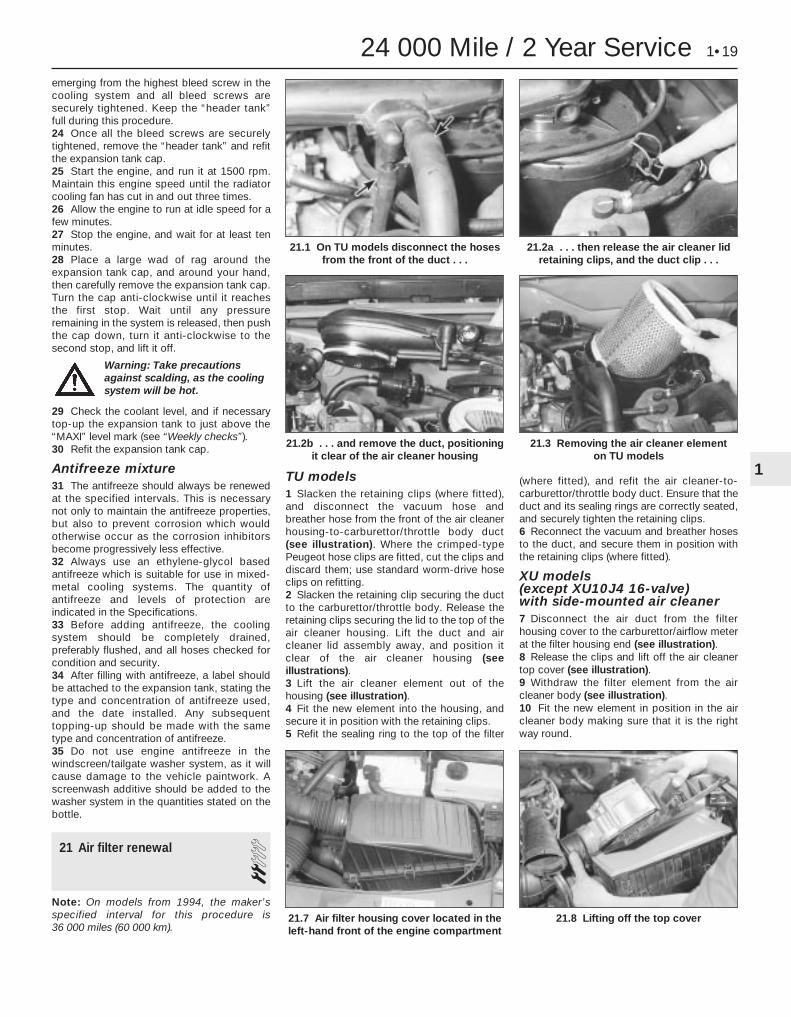
emerging from the highest bleed screw in thecooling system and all bleed screws aresecurely tightened. Keep the “header tank”full during this procedure.24 Once all the bleed screws are securelytightened, remove the “header tank” and refitthe expansion tank cap.25 Start the engine, and run it at 1500 rpm.Maintain this engine speed until the radiatorcooling fan has cut in and out three times.26 Allow the engine to run at idle speed for afew minutes.27 Stop the engine, and wait for at least tenminutes.28 Place a large wad of rag around theexpansion tank cap, and around your hand,then carefully remove the expansion tank cap.Turn the cap anti-clockwise until it reachesthe first stop. Wait until any pressureremaining in the system is released, then pushthe cap down, turn it anti-clockwise to thesecond stop, and lift it off.
29 Check the coolant level, and if necessarytop-up the expansion tank to just above the“MAXI” level mark (see “Weekly checks”).30 Refit the expansion tank cap.
Antifreeze mixture31 The antifreeze should always be renewedat the specified intervals. This is necessarynot only to maintain the antifreeze properties,but also to prevent corrosion which wouldotherwise occur as the corrosion inhibitorsbecome progressively less effective.32 Always use an ethylene-glycol basedantifreeze which is suitable for use in mixed-metal cooling systems. The quantity ofantifreeze and levels of protection areindicated in the Specifications.33 Before adding antifreeze, the coolingsystem should be completely drained,preferably flushed, and all hoses checked forcondition and security.34 After filling with antifreeze, a label shouldbe attached to the expansion tank, stating thetype and concentration of antifreeze used,and the date installed. Any subsequenttopping-up should be made with the sametype and concentration of antifreeze.35 Do not use engine antifreeze in thewindscreen/tailgate washer system, as it willcause damage to the vehicle paintwork. Ascreenwash additive should be added to thewasher system in the quantities stated on thebottle.
21 Air filter renewal 2Note: On models from 1994, the maker’sspecified interval for this procedure is 36 000 miles (60 000 km).
TU models1 Slacken the retaining clips (where fitted),and disconnect the vacuum hose andbreather hose from the front of the air cleanerhousing-to-carburettor/throttle body duct(see illustration). Where the crimped-typePeugeot hose clips are fitted, cut the clips anddiscard them; use standard worm-drive hoseclips on refitting.2 Slacken the retaining clip securing the ductto the carburettor/throttle body. Release theretaining clips securing the lid to the top of theair cleaner housing. Lift the duct and aircleaner lid assembly away, and position itclear of the air cleaner housing (seeillustrations).3 Lift the air cleaner element out of thehousing (see illustration).4 Fit the new element into the housing, andsecure it in position with the retaining clips.5 Refit the sealing ring to the top of the filter
(where fitted), and refit the air cleaner-to-carburettor/throttle body duct. Ensure that theduct and its sealing rings are correctly seated,and securely tighten the retaining clips.6 Reconnect the vacuum and breather hosesto the duct, and secure them in position withthe retaining clips (where fitted).
XU models (except XU10J4 16-valve) with side-mounted air cleaner7 Disconnect the air duct from the filterhousing cover to the carburettor/airflow meterat the filter housing end (see illustration).8 Release the clips and lift off the air cleanertop cover (see illustration).9 Withdraw the filter element from the aircleaner body (see illustration).10 Fit the new element in position in the aircleaner body making sure that it is the rightway round.
24 000 Mile / 2 Year Service 1•19
21.2b . . . and remove the duct, positioningit clear of the air cleaner housing
21.8 Lifting off the top cover21.7 Air filter housing cover located in theleft-hand front of the engine compartment
21.3 Removing the air cleaner element on TU models
21.2a . . . then release the air cleaner lidretaining clips, and the duct clip . . .
21.1 On TU models disconnect the hosesfrom the front of the duct . . .
1
Warning: Take precautionsagainst scalding, as the coolingsystem will be hot.

11 Refit the top cover and attach the clips.12 Reconnect the air duct.
XU models (except XU10J4 16-valve) with top-mounted air cleaner13 Slacken the retaining clip, and disconnectthe inlet duct from the front of the cylinderhead cover (see illustration).14 Slacken and remove the two retainingscrews situated at the front of the cylinderhead cover, then release the two air filtercover retaining clips. Remove the filter coverfrom the cylinder head cover, and withdrawthe filter element (see illustrations).15 Fit the new element in position in thecylinder head cover. Refit the filter cover, andsecure it with its retaining screws and clips.16 Reconnect the inlet duct to the cylinderhead cover, and tighten its retaining clip.
XU10J4 16-valve models17 Disconnect the air duct and remove thecover from the end of the air cleaner body.18 Withdraw the air filter element notingwhich way round it is fitted.19 Fit the new element in the body, ensuringthat it is fitted the correct way round.20 Refit the cover and air duct.
22 Ignition system check 3Note: On models from 1994, the maker’sspecified interval for this procedure is 18 000 miles (30 000 km).
1 The ignition system components should bechecked for damage or deterioration asdescribed under the relevant sub-heading.
Ignition systems incorporating a distributorGeneral component check2 The spark plug (HT) leads should bechecked whenever new spark plugs areinstalled in the engine.3 Ensure that the leads are numbered beforeremoving them, to avoid confusion whenrefitting. Pull the leads from the plugs bygripping the end fitting, not the lead,otherwise the lead connection may befractured.4 Check inside the end fitting for signs ofcorrosion, which will look like a white crustypowder. Push the end fitting back onto thespark plug, ensuring that it is a tight fit on theplug. If not, remove the lead again, and usepliers to carefully crimp the metal connectorinside the end fitting until it fits securely on theend of the spark plug.5 Using a clean rag, wipe the entire length ofthe lead to remove any built-up dirt and
grease. Once the lead is clean, check forburns, cracks and other damage. Do not bendthe lead excessively, or pull the leadlengthways - the conductor inside mightbreak.6 Disconnect the other end of the lead fromthe distributor cap. Again, pull only on the endfitting. Check for corrosion and a tight fit in thesame manner as the spark plug end. If anohmmeter is available, check the resistance ofthe lead by connecting the meter between thespark plug end of the lead and the segmentinside the distributor cap. Refit the leadsecurely on completion.7 Check the remaining leads one at a time, inthe same way.8 If new spark plug (HT) leads are required,purchase a set for your specific car andengine.9 Remove the distributor cap by unscrewingits retaining screws. Wipe it clean, andcarefully inspect it inside and out for signs ofcracks, carbon tracks (tracking) and worn,burned or loose contacts; check that thecap’s carbon brush is unworn, free to moveagainst spring pressure, and making goodcontact with the rotor arm. Also inspect thecap seal for signs of wear or damage, andrenew if necessary. Remove the rotor armfrom the distributor shaft and inspect it (seeillustration). It is common practice to renewthe cap and rotor arm whenever new sparkplug (HT) leads are fitted. When fitting a newcap, remove the leads from the old cap one ata time, and fit them to the new cap in theexact same location - do not simultaneouslyremove all the leads from the old cap, or firingorder confusion may occur. On refitting,
1•20 24 000 Mile / 2 Year Service
21.9 Removing the air filter element 21.14a . . . then slacken the retainingscrews (arrowed) . . .
21.14d . . . and withdraw the filter element21.14c Lift off the filter cover . . .21.14b . . . and release the retaining clips
21.13 Disconnect the intake duct from thefront of the cylinder head cover . . .
Warning: Voltages produced byan electronic ignition systemare considerably higher thanthose produced by conventional
ignition systems. Extreme care must betaken if working on the system with theignition switched on. Persons withsurgically-implanted cardiac pacemakerdevices should keep well clear of theignition circuits, components and testequipment.

ensure that the arm is securely pressed ontothe shaft, and tighten the cap retaining screwssecurely.10 Even with the ignition system in first classcondition, some engines may still occasionallyexperience poor starting, attributable to dampignition components. To disperse moisture, awater-dispersant aerosol can be veryeffective.
Ignition timing check and adjustment11 Check the ignition timing as described inChapter 5B.
Static (distributorless) ignition systems
General component check12 On all except 1998 cc 16-valve models,check the condition of the HT leads asdescribed above. On 1998 cc 16-valvemodels, there are no HT leads, so the onlyrelevant check is that all the primary (LT)circuit wiring connectors are clean and free ofcorrosion.
Ignition timing check and adjustment13 Refer to Chapter 5B.
23 Automatic transmission fluidrenewal 2
Note: On models from 1994, the maker’sspecified interval for this procedure is 18 000 miles (30 000 km).1 Take the vehicle on a short run, to warm thetransmission up to normal operatingtemperature.2 Park the car on level ground, then switch offthe ignition and apply the handbrake firmly.For improved access, jack up the front of thecar and support it securely on axle stands(see “Jacking and Vehicle Support”). Note
that, when refilling and checking the fluidlevel, the car must be lowered to the ground,and level, to ensure accuracy.3 Remove the dipstick, then position asuitable container under the transmission. Thetransmission has two drain plugs: one on thesump, and another on the bottom of thedifferential housing (see illustration).4 Unscrew both drain plugs, and allow thefluid to drain completely into the container.
5 When the fluid has finished draining, cleanthe drain plug threads and those of thetransmission casing. Fit a new sealing washerto each drain plug, and refit the plugs to thetransmission, tightening each securely. If thecar was raised for the draining operation, nowlower it to the ground. Make sure that the caris level (front-to-rear and side-to-side).6 Refilling the transmission is an awkwardoperation, adding the specified type of fluid tothe transmission a little at a time via thedipstick tube. Use a funnel with a fine meshgauze, to avoid spillage, and to ensure that noforeign matter enters the transmission. Allowplenty of time for the fluid level to settleproperly.7 Once the level is up to the MAX mark on thedipstick, refit the dipstick. Start the engine,and allow it to idle for a few minutes. Switchthe engine off, then recheck the level,topping-up if necessary. Take the car on ashort run to fully distribute the new fluidaround the transmission, then recheck thefluid level as described in “Weekly checks”.
24 Brake fluid renewal 2Note: On models from 1994, the maker’sspecified interval for this procedure is every 2 years, regardless of mileage.
1 The procedure is similar to that for thebleeding of the hydraulic system as describedin Chapter 9, except that the brake fluidreservoir should be emptied by siphoning,using a clean poultry baster or similar beforestarting, and allowance should be made forthe old fluid to be expelled when bleeding asection of the circuit.2 Working as described in Chapter 9, openthe first bleed screw in the sequence, andpump the brake pedal gently until nearly allthe old fluid has been emptied from themaster cylinder reservoir. Top-up to the“MAX” level with new fluid, and continuepumping until only the new fluid remains in thereservoir, and new fluid can be seen emergingfrom the bleed screw. Tighten the screw, andtop the reservoir level up to the “MAX” levelline.
3 Work through all the remaining bleedscrews in the sequence until new fluid can beseen at all of them. Be careful to keep themaster cylinder reservoir topped-up to abovethe “MIN” level at all times, or air may enterthe system and greatly increase the length ofthe task.4 When the operation is complete, check thatall bleed screws are securely tightened, andthat their dust caps are refitted. Wash off alltraces of spilt fluid, and recheck the mastercylinder reservoir fluid level.5 Check the operation of the brakes beforetaking the car on the road.
24 000 Mile / 2 Year Service 1•21
23.3 Automatic transmission fluid drainplugs (arrowed). Transmission is refilled
via the dipstick tube (1)
22.9 The rotor arm is a push fit on thedistributor shaft
1
Warning: If the fluid is hot, takeprecautions against scalding.Clean the drain plugs, beingespecially careful to wipe any
metallic particles off the magnetic insert.Discard the original sealing washers;these should be renewed whenever theyare disturbed.
Warning: Brake hydraulic fluidcan harm your eyes anddamage painted surfaces, souse extreme caution when
handling and pouring it. Do not use fluidthat has been standing open for sometime, as it absorbs moisture from the air.Excess moisture content can cause adangerous loss of braking effectiveness.
Old hydraulic fluid isinvariably much darker incolour than the new, makingit easy to distinguish the two.

25 Timing belt renewal 4Note: On models from 1994, the maker’sspecified interval for this procedure is 72 000 miles (120 000 km).
Refer to the relevant Part of Chapter 2.
26 Manual transmission oil level check 2
Note: On models from 1994, the maker’sspecified interval for this procedure is 36 000 miles (60 000 km).Note: A suitable square-section wrench maybe required to undo the transmissionfiller/level plug on some models. Thesewrenches can be obtained from most motorfactors or your Peugeot dealer.Haynes Hint: It may be possible to use thesquare end fitting on a ratchet handle (asfound in a typical socket set) to undo theplug.1 Park the car on a level surface. The oil levelmust be checked before the car is driven, orat least 5 minutes after the engine has beenswitched off. If the oil level is checkedimmediately after driving the car, some of theoil will remain distributed around thetransmission components, resulting in aninaccurate level reading.2 Turn the steering wheel on full left-handlock, then where applicable remove the coverfor access to the left-hand side of thetransmission.3 Wipe clean the area around the filler/levelplug, which is on the left-hand end of thetransmission. Unscrew the plug and clean it;discard the sealing washer (see illustration).4 The oil level should reach the lower edge ofthe filler/level hole. A certain amount of oil willhave gathered behind the filler/level plug, andwill trickle out when it is removed; this doesnot necessarily indicate that the level is
correct. To ensure that a true level isestablished, wait until the initial trickle hasstopped, then add oil as necessary until atrickle of new oil can be seen emerging (seeillustration). The level will be correct whenthe flow ceases; use only good-quality oil ofthe specified type.5 Filling the transmission with oil is anextremely awkward operation; above all, allowplenty of time for the oil level to settle properlybefore checking it. If a large amount had to beadded to the transmission, and a largeamount flows out on checking the level, refitthe filler/level plug and take the vehicle on ashort journey so that the new oil is distributedfully around the transmission components,then recheck the level when it has settledagain.6 If the transmission has been overfilled sothat oil flows out as soon as the filler/levelplug is removed, first check that the car iscompletely level (front-to-rear and side-to-side), and allow any surplus oil to drain off intoa suitable container.7 When the level is correct, fit a new sealingwasher to the filler/level plug. Refit the plug,tightening it to the specified torque wrenchsetting. Wash off any spilt oil then whereapplicable refit the access cover.
27 Rear brake shoe check -models with rear drum brakes 2
Note: On models from 1994, the maker’sspecified interval for this procedure is 36 000 miles (60 000 km).
Remove the rear brake drums, and checkthe brake shoes for signs of wear orcontamination. At the same time, also inspectthe wheel cylinders for signs of leakage, andthe brake drum for signs of wear. Refer to therelevant Sections of Chapter 9 for furtherinformation.
28 Pollen filter renewal 1Note: On models from 1994, the maker’sspecified interval for this procedure is 9000 miles (15 000 km) or 12 months.1 On later models, a pollen filter is fitted.2 Open the bonnet.3 Release the securing clips, and withdrawthe plastic cover from the heater air inlet in thepassenger’s side of the scuttle at the rear ofthe engine compartment.4 Unclip the pollen filter from the heater airinlet duct (see illustration).5 Refitting is a reversal of removal.
29 Emissions control systems check 2
Note: On models from 1994, the maker’sspecified interval for this procedure is 18 000 miles (30 000 km).1 Details of the emission control systemcomponents are given in Chapter 4D.2 Checking consists simply of a visual checkfor obvious signs of damaged or leakinghoses and joints.3 Detailed checking and testing of theevaporative and/or exhaust emission systems(as applicable) should be entrusted to aPeugeot dealer.
30 Road test 1Note: On models from 1994, the maker’sspecified interval for this procedure is 18 000 miles (30 000 km).
Instruments and electrical equipment1 Check the operation of all instruments andelectrical equipment.
36 000 Mile / 3 Year Service
1•22 36 000 Mile / 3 Year Service
28.4 Removing the pollen filter from theheater air intake duct
26.4 Toping-up the transmission oil level
26.3 Using a square-section wrench tounscrew the transmission filler/level plug
(MA transmission shown)

2 Make sure that all instruments read correctly,and switch on all electrical equipment in turn, tocheck that it functions properly.
Steering and suspension3 Check for any abnormalities in the steering,suspension, handling or road “feel”.4 Drive the vehicle, and check that there areno unusual vibrations or noises.5 Check that the steering feels positive, withno excessive “sloppiness”, or roughness, andcheck for any suspension noises whencornering and driving over bumps.
Drivetrain6 Check the performance of the engine, clutch(where applicable), transmission and driveshafts.7 Listen for any unusual noises from theengine, clutch and transmission.8 Make sure that the engine runs smoothlywhen idling, and that there is no hesitationwhen accelerating.9 Check that, where applicable, the clutchaction is smooth and progressive, that the
drive is taken up smoothly, and that the pedaltravel is not excessive. Also listen for anynoises when the clutch pedal is depressed.10 On manual transmission models, checkthat all gears can be engaged smoothlywithout noise, and that the gear lever action isnot abnormally vague or “notchy”.11 On automatic transmission models, makesure that all gearchanges occur smoothly,without snatching, and without an increase inengine speed between changes. Check thatall the gear positions can be selected with thevehicle at rest. If any problems are found, theyshould be referred to a Peugeot dealer.12 Listen for a metallic clicking sound fromthe front of the vehicle, as the vehicle is drivenslowly in a circle with the steering on full-lock.Carry out this check in both directions. If aclicking noise is heard, this indicates wear in adriveshaft joint, in which case the completedriveshaft must be renewed (see Chapter 8).
Braking system13 Make sure that the vehicle does not pull to
one side when braking, and that the wheelsdo not lock prematurely when braking hard.14 Check that there is no vibration throughthe steering when braking.15 Check that the handbrake operatescorrectly, without excessive movement of thelever, and that it holds the vehicle stationaryon a slope.16 Test the operation of the brake servo unitas follows. Depress the footbrake four or fivetimes to exhaust the vacuum, then start theengine. As the engine starts, there should be anoticeable “give” in the brake pedal asvacuum builds up. Allow the engine to run forat least two minutes, and then switch it off. Ifthe brake pedal is now depressed again, itshould be possible to detect a hiss from theservo as the pedal is depressed. After aboutfour or five applications, no further hissingshould be heard, and the pedal should feelconsiderably harder.
36 000 Mile / 3 Year Service 1•23
1

2A
Engine (general)Designation . . . . . . . . . . . . . . . . . . . . . . . . . . . . . . . . . . . . . . . . . . . . . . . TU3Engine code:
UK models (10/92 to 08/93) . . . . . . . . . . . . . . . . . . . . . . . . . . . . . . . . KDX (TU3MC/L/Z)Non-UK models (07/87 to 06/88) . . . . . . . . . . . . . . . . . . . . . . . . . . . . K1A (TU3)Non-UK models (07/88-on) . . . . . . . . . . . . . . . . . . . . . . . . . . . . . . . . . K1G (TU3A)Non-UK models (11/87-on) . . . . . . . . . . . . . . . . . . . . . . . . . . . . . . . . . K3A (TU3TR)Non-UK models (1993-on) . . . . . . . . . . . . . . . . . . . . . . . . . . . . . . . . . K2D (TU3F2/K)
Capacity . . . . . . . . . . . . . . . . . . . . . . . . . . . . . . . . . . . . . . . . . . . . . . . . . 1360 ccBore . . . . . . . . . . . . . . . . . . . . . . . . . . . . . . . . . . . . . . . . . . . . . . . . . 75.00 mmStroke . . . . . . . . . . . . . . . . . . . . . . . . . . . . . . . . . . . . . . . . . . . . . . . . . 77.00 mmDirection of crankshaft rotation . . . . . . . . . . . . . . . . . . . . . . . . . . . . . . . Clockwise (viewed from right-hand side of vehicle)No 1 cylinder location . . . . . . . . . . . . . . . . . . . . . . . . . . . . . . . . . . . . . . . At transmission end of blockCompression ratio:
Except K3A . . . . . . . . . . . . . . . . . . . . . . . . . . . . . . . . . . . . . . . . . . . . . 9.3 : 1K3A . . . . . . . . . . . . . . . . . . . . . . . . . . . . . . . . . . . . . . . . . . . . . . . . . 8.3 : 1
*The engine code is situated on the front left-hand end of the cylinder block. It is either stamped on a plate which is riveted to the block(aluminium block engines) or stamped directly on the cylinder block (cast-iron block engines). The code given in brackets is the factory identifi-cation number, and is not often referred to by this manual.
CamshaftDrive . . . . . . . . . . . . . . . . . . . . . . . . . . . . . . . . . . . . . . . . . . . . . . . . . Toothed beltNumber of bearings . . . . . . . . . . . . . . . . . . . . . . . . . . . . . . . . . . . . . . . . 5Camshaft bearing journal diameter (outside diameter):
No 1 . . . . . . . . . . . . . . . . . . . . . . . . . . . . . . . . . . . . . . . . . . . . . . . . . 36.950 to 36.925 mmNo 2 . . . . . . . . . . . . . . . . . . . . . . . . . . . . . . . . . . . . . . . . . . . . . . . . . 40.650 to 40.625 mmNo 3 . . . . . . . . . . . . . . . . . . . . . . . . . . . . . . . . . . . . . . . . . . . . . . . . . 41.250 to 41.225 mmNo 4 . . . . . . . . . . . . . . . . . . . . . . . . . . . . . . . . . . . . . . . . . . . . . . . . . 41.850 to 41.825 mmNo 5 . . . . . . . . . . . . . . . . . . . . . . . . . . . . . . . . . . . . . . . . . . . . . . . . . 42.450 to 42.425 mm
Cylinder head bearing journal diameter (inside diameter):No 1 . . . . . . . . . . . . . . . . . . . . . . . . . . . . . . . . . . . . . . . . . . . . . . . . . 37.000 to 37.039 mmNo 2 . . . . . . . . . . . . . . . . . . . . . . . . . . . . . . . . . . . . . . . . . . . . . . . . . 40.700 to 47.739 mmNo 3 . . . . . . . . . . . . . . . . . . . . . . . . . . . . . . . . . . . . . . . . . . . . . . . . . 41.300 to 41.339 mmNo 4 . . . . . . . . . . . . . . . . . . . . . . . . . . . . . . . . . . . . . . . . . . . . . . . . . 41.900 to 41.939 mmNo 5 . . . . . . . . . . . . . . . . . . . . . . . . . . . . . . . . . . . . . . . . . . . . . . . . . 42.500 to 42.539 mm
Valve clearances (engine cold)Inlet . . . . . . . . . . . . . . . . . . . . . . . . . . . . . . . . . . . . . . . . . . . . . . . . . 0.20 mmExhaust . . . . . . . . . . . . . . . . . . . . . . . . . . . . . . . . . . . . . . . . . . . . . . . . . 0.40 mm
Chapter 2 Part A:TU petrol engine in-car repair procedures
Camshaft and rocker arms - removal, inspection and refitting . . . . .10Camshaft oil seal - renewal . . . . . . . . . . . . . . . . . . . . . . . . . . . . . . . . .8Compression test . . . . . . . . . . . . . . . . . . . . . . . . . . . . . . . . . . . . . . . . .2Crankshaft oil seals - renewal . . . . . . . . . . . . . . . . . . . . . . . . . . . . . . .14Cylinder head - removal and refitting . . . . . . . . . . . . . . . . . . . . . . . . .11Cylinder head cover - removal and refitting . . . . . . . . . . . . . . . . . . . . .4Engine assembly/valve timing holes -
general information and usage . . . . . . . . . . . . . . . . . . . . . . . . . . . . .3Engine oil and filter renewal . . . . . . . . . . . . . . . . . . . . . . .See Chapter 1Engine oil level check . . . . . . . . . . . . . . . . . . . . . .See “Weekly checks”
Engine/transmission mountings - inspection and renewal . . . . . . . . .16Flywheel - removal, inspection and refitting . . . . . . . . . . . . . . . . . . . .15General information . . . . . . . . . . . . . . . . . . . . . . . . . . . . . . . . . . . . . . .1Oil pump - removal, inspection and refitting . . . . . . . . . . . . . . . . . . .13Sump - removal and refitting . . . . . . . . . . . . . . . . . . . . . . . . . . . . . . .12Timing belt - general information, removal and refitting . . . . . . . . . . . .6Timing belt covers - removal and refitting . . . . . . . . . . . . . . . . . . . . . .5Timing belt tensioner and sprockets -
removal, inspection and refitting . . . . . . . . . . . . . . . . . . . . . . . . . . .7Valve clearances - checking and adjustment . . . . . . . . . . . . . . . . . . . .9
2A•1
Easy, suitable fornovice with littleexperience
Fairly easy, suitablefor beginner withsome experience
Fairly difficult,suitable for competentDIY mechanic
Difficult, suitable forexperienced DIYmechanic
Very difficult,suitable for expertDIY or professional
D e g r e e s o f d i f f i c u l t y
S p e c i f i c a t i o n s
Contents

Lubrication systemOil pump type . . . . . . . . . . . . . . . . . . . . . . . . . . . . . . . . . . . . . . . . . . . . . Gear-type, chain-driven off the crankshaftMinimum oil pressure at 90°C:
Except K2D . . . . . . . . . . . . . . . . . . . . . . . . . . . . . . . . . . . . . . . . . . . . . 4 bars at 4000 rpmK2D . . . . . . . . . . . . . . . . . . . . . . . . . . . . . . . . . . . . . . . . . . . . . . . . . 3 bars at 2000 rpm
Oil pressure warning switch operating pressure . . . . . . . . . . . . . . . . . . 0.8 bars
Torque wrench settings Nm lbf ftCylinder head cover nuts . . . . . . . . . . . . . . . . . . . . . . . . . . . . . . . . . . . . 16 12Timing belt cover bolts . . . . . . . . . . . . . . . . . . . . . . . . . . . . . . . . . . . . . . 8 6Crankshaft pulley retaining bolts . . . . . . . . . . . . . . . . . . . . . . . . . . . . . . 8 6Timing belt tensioner pulley nut . . . . . . . . . . . . . . . . . . . . . . . . . . . . . . . 23 17Camshaft sprocket retaining bolt . . . . . . . . . . . . . . . . . . . . . . . . . . . . . . 80 59Crankshaft sprocket retaining bolt . . . . . . . . . . . . . . . . . . . . . . . . . . . . . 110 81Camshaft thrust fork retaining bolt . . . . . . . . . . . . . . . . . . . . . . . . . . . . . 16 12Cylinder head bolts (aluminium block engine):
Stage 1 . . . . . . . . . . . . . . . . . . . . . . . . . . . . . . . . . . . . . . . . . . . . . . . . 20 15Stage 2 . . . . . . . . . . . . . . . . . . . . . . . . . . . . . . . . . . . . . . . . . . . . . . . . Angle-tighten a further 240°
Cylinder head bolts (cast-iron block engine):Stage 1 . . . . . . . . . . . . . . . . . . . . . . . . . . . . . . . . . . . . . . . . . . . . . . . . 20 15Stage 2 . . . . . . . . . . . . . . . . . . . . . . . . . . . . . . . . . . . . . . . . . . . . . . . . Angle-tighten a further 120°Stage 3 . . . . . . . . . . . . . . . . . . . . . . . . . . . . . . . . . . . . . . . . . . . . . . . . Angle-tighten a further 120°
Sump drain plug . . . . . . . . . . . . . . . . . . . . . . . . . . . . . . . . . . . . . . . . . . . 30 22Sump retaining nuts and bolts . . . . . . . . . . . . . . . . . . . . . . . . . . . . . . . . 8 6Oil pump retaining bolts . . . . . . . . . . . . . . . . . . . . . . . . . . . . . . . . . . . . . 8 6Flywheel retaining nuts and bolts . . . . . . . . . . . . . . . . . . . . . . . . . . . . . . 65 48Piston oil jet spray tube bolts - 1587 cc models . . . . . . . . . . . . . . . . . . 10 7Big-end bearing cap nuts . . . . . . . . . . . . . . . . . . . . . . . . . . . . . . . . . . . . 40 30Main bearing ladder casting (aluminium block engine):
11 mm bolts:Stage 1 . . . . . . . . . . . . . . . . . . . . . . . . . . . . . . . . . . . . . . . . . . . . . . 20 15Stage 2 . . . . . . . . . . . . . . . . . . . . . . . . . . . . . . . . . . . . . . . . . . . . . . Angle-tighten a further 45°
6 mm bolts . . . . . . . . . . . . . . . . . . . . . . . . . . . . . . . . . . . . . . . . . . . . . 8 6Main bearing cap bolts (cast-iron block engine):
Stage 1 . . . . . . . . . . . . . . . . . . . . . . . . . . . . . . . . . . . . . . . . . . . . . . . . 20 15Stage 2 . . . . . . . . . . . . . . . . . . . . . . . . . . . . . . . . . . . . . . . . . . . . . . . . Angle-tighten a further 45°
2A•2 TU engine in-car repair procedures
1 General information
How to use this Chapter1 This Part of Chapter 2 describes thoserepair procedures that can reasonably becarried out on the TU series engine while itremains in the car. If the engine has beenremoved from the car and is being dismantledas described in Part C, any preliminarydismantling procedures can be ignored. Referto Part B for the XU series petrol engine.2 Note that, while it may be possiblephysically to overhaul items such as thepiston/connecting rod assemblies while theengine is in the car, such tasks are notnormally carried out as separate operations.Usually, several additional procedures (not tomention the cleaning of components andoilways) have to be carried out. For thisreason, all such tasks are classed as majoroverhaul procedures, and are described inPart C of this Chapter.3 Part C describes the removal of theengine/transmission from the vehicle, and thefull overhaul procedures that can then becarried out.
TU series engine description4 The TU series engine is a well-provenengine which has been fitted to manyprevious Peugeot and Citroën vehicles. Theengine is of the in-line four-cylinder, overheadcamshaft (OHC) type, mounted transversely atthe front of the car. The clutch andtransmission are attached to its left-hand end.The 405 range is fitted with the 1360 ccversion of the engine; carburettor and fuel-injected versions are available (carburettorversions not available in the UK).5 The crankshaft runs in five main bearings.Thrustwashers are fitted to No 2 main bearing(upper half) to control crankshaft endfloat.6 The connecting rods rotate on horizontally-split bearing shells at their big-ends. Thepistons are attached to the connecting rodsby gudgeon pins, which are an interference fitin the connecting rod small-end eyes. Thealuminium-alloy pistons are fitted with threepiston rings - two compression rings and anoil control ring.7 Where the cylinder block is made ofaluminium, replaceable wet liners are fitted.Sealing O-rings are fitted at the base of eachliner, to prevent the escape of coolant into thesump.8 Where the cylinder block is made from cast
iron, the cylinder bores are an integral part ofthe cylinder block. On this type of engine thecylinder bores are sometimes referred to ashaving dry liners.9 The inlet and exhaust valves are eachclosed by coil springs, and operate in guidespressed into the cylinder head; the valve seatinserts are also pressed into the cylinderhead, and can be renewed separately if worn.10 The camshaft is driven by a toothedtiming belt, and operates the eight valves viarocker arms. Valve clearances are adjusted bya screw-and-locknut arrangement. Thecamshaft rotates directly in the cylinder head.The timing belt also drives the coolant pump.11 Lubrication is by means of an oil pump,which is driven (via a chain and sprocket) offthe right-hand end of the crankshaft. It drawsoil through a strainer located in the sump, andthen forces it through an externally-mountedfilter into galleries in the cylinderblock/crankcase. From there, the oil isdistributed to the crankshaft (main bearings)and camshaft. The big-end bearings aresupplied with oil via internal drillings in thecrankshaft, while the camshaft bearings alsoreceive a pressurised supply. The camshaftlobes and valves are lubricated by splash, asare all other engine components.

12 Throughout this manual, it is oftennecessary to identify the engines not only bytheir capacity, but also by their engine codewhich can be found on the left-hand end ofthe front face of the cylinder block. On modelswith an aluminium cylinder block the code isstamped on a plate which is riveted to theblock, and on models with a cast iron cylinderblock the number is stamped on a machinedsurface on the cylinder block, at the flywheelend. The first part of the engine number givesthe engine code - eg “KDX” (see illustration).
Repair operations possible withthe engine in the car13 The following work can be carried out withthe engine in the car:a) Compression pressure - testing.b) Cylinder head cover - removal and refitting.c) Timing belt covers - removal and refitting.d) Timing belt - removal, refitting and
adjustment.e) Timing belt tensioner and sprockets -
removal and refitting.f) Camshaft oil seal(s) - renewal.g) Camshaft and rocker arms - removal,
inspection and refitting.*h) Cylinder head - removal and refitting.i) Cylinder head and pistons - decarbonising.j) Sump - removal and refitting.k) Oil pump - removal, overhaul and refitting.l) Crankshaft oil seals - renewal.m)Engine/transmission mountings -
inspection and renewal.n) Flywheel - removal, inspection and refitting.
*The cylinder head must be removed for thesuccessful completion of this work. Refer toSection 10 for details.
2 Compression test
1 When engine performance is down, or ifmisfiring occurs which cannot be attributed tothe ignition or fuel systems, a compressiontest can provide diagnostic clues as to theengine’s condition. If the test is performedregularly, it can give warning of trouble beforeany other symptoms become apparent.2 The engine must be fully warmed-up to
normal operating temperature, the batterymust be fully charged, and all the spark plugsmust be removed (Chapter 1). The aid of anassistant will also be required.3 On carburettor models, disable the ignitionsystem by disconnecting the ignition HT coillead from the distributor cap and earthing iton the cylinder block. Use a jumper lead orsimilar wire to make a good connection.4 On fuel-injected models, disable theignition system by disconnecting the LT wiringconnector from the ignition HT coil(s),referring to Chapter 5 for further information.5 Fit a compression tester to the No 1cylinder spark plug hole - the type of testerwhich screws into the plug thread is to bepreferred.6 Have the assistant hold the throttle wideopen, and crank the engine on the startermotor. After one or two revolutions, thecompression pressure should build up to amaximum figure, and then stabilise. Recordthe highest reading obtained.7 Repeat the test on the remaining cylinders,recording the pressure in each.8 All cylinders should produce very similarpressures; a difference of more than 2 barsbetween any two cylinders indicates a fault.Note that the compression should build upquickly in a healthy engine; low compressionon the first stroke, followed by gradually-increasing pressure on successive strokes,indicates worn piston rings. A lowcompression reading on the first stroke, whichdoes not build up during successive strokes,indicates leaking valves or a blown headgasket (a cracked head could also be thecause). Deposits on the undersides of thevalve heads can also cause low compression.9 Although Peugeot do not specify exactcompression pressures, as a guide, anycylinder pressure of below 10 bars can beconsidered as less than healthy. Refer to aPeugeot dealer or other specialist if in doubtas to whether a particular pressure reading isacceptable.10 If the pressure in any cylinder is low, carryout the following test to isolate the cause.Introduce a teaspoonful of clean oil into thatcylinder through its spark plug hole, andrepeat the test.11 If the addition of oil temporarily improvesthe compression pressure, this indicates thatbore or piston wear is responsible for thepressure loss. No improvement suggests thatleaking or burnt valves, or a blown headgasket, may be to blame.12 A low reading from two adjacent cylindersis almost certainly due to the head gaskethaving blown between them; the presence ofcoolant in the engine oil will confirm this.13 If one cylinder is about 20 percent lowerthan the others and the engine has a slightlyrough idle, a worn camshaft lobe could be thecause.14 If the compression reading is unusuallyhigh, the combustion chambers are probablycoated with carbon deposits. If this is the
case, the cylinder head should be removedand decarbonised.15 On completion of the test, refit the sparkplugs and reconnect the ignition system.
3 Engine assembly/valvetiming holes - generalinformation and usage
3Note: Do not attempt to rotate the enginewhilst the crankshaft/camshaft are locked inposition. If the engine is to be left in this statefor a long period of time, it is a good idea toplace warning notices inside the vehicle, andin the engine compartment. This will reducethe possibility of the engine being accidentallycranked on the starter motor, which is likely tocause damage with the locking pins in place.1 On all models, timing holes are drilled in thecamshaft sprocket and in the rear of theflywheel. The holes are used to ensure thatthe crankshaft and camshaft are correctlypositioned when assembling the engine (toprevent the possibility of the valves contactingthe pistons when refitting the cylinder head),or refitting the timing belt. When the timingholes are aligned with the special holes in thecylinder head and the front of the cylinderblock, suitable diameter pins can be insertedto lock both the camshaft and crankshaft inposition, preventing them from rotating.Proceed as follows.2 Remove the timing belt upper cover asdescribed in Section 5.3 The crankshaft must now be turned untilthe timing hole in the camshaft sprocket isaligned with the corresponding hole in thecylinder head. The holes are aligned when thecamshaft sprocket hole is in the 2 o’clockposition, when viewed from the right-handend of the engine. The crankshaft can beturned by using a spanner on the crankshaftsprocket bolt, noting that it should always berotated in a clockwise direction (viewed fromthe right-hand end of the engine).4 With the camshaft sprocket hole correctlypositioned, insert a 6 mm diameter bolt or drillthrough the hole in the front, left-hand flangeof the cylinder block, and locate it in thetiming hole in the rear of the flywheel (seeillustration). Note that it may be necessary to
TU engine in-car repair procedures 2A•3
3.4 Insert a 6 mm bolt (arrowed) throughhole in cylinder block flange and into
timing hole in the flywheel . . .
1.12 Engine code is stamped on a plate(arrowed) attached to the front of thecylinder block - viewed from above
2A

rotate the crankshaft slightly, to get the holesto align.5 With the flywheel correctly positioned,insert a 10 mm diameter bolt or a drill throughthe timing hole in the camshaft sprocket, andlocate it in the hole in the cylinder head (seeillustration).6 The crankshaft and camshaft are nowlocked in position, preventing unnecessaryrotation.
4 Cylinder head cover -removal and refitting 2
Removal1 Disconnect the battery negative lead.2 Where necessary, undo the bolts securing
the HT lead retaining clips to the rear of thecylinder head cover, and position the clipsclear of the cover.3 Slacken the retaining clip, and disconnectthe breather hose from the left-hand end ofthe cylinder head cover (see illustration).Where the original crimped-type Peugeothose clip is still fitted, cut it off and discard it.Use a standard worm-drive clip on refitting.4 Undo the two retaining nuts, and removethe washer from each of the cylinder headcover studs (see illustration).5 Lift off the cylinder head cover, and removeit along with its rubber seal (see illustration).Examine the seal for signs of damage anddeterioration, and if necessary, renew it.6 Lift off the spacer from each stud, andremove the oil baffle plate (see illustrations).
Refitting7 Carefully clean the cylinder head and covermating surfaces, and remove all traces of oil.8 Fit the rubber seal over the edge of thecylinder head cover, ensuring that it iscorrectly located along its entire length (seeillustration).9 Refit the oil baffle plate to the engine, andlocate the spacers in their recesses in thebaffle plate.10 Carefully refit the cylinder head cover tothe engine, taking great care not to displacethe rubber seal.11 Check that the seal is correctly located,then refit the washers and cover retainingnuts, and tighten them to the specified torque.12 Where necessary, refit the HT lead clips to
the rear of the head cover, and securelytighten their retaining bolts.13 Reconnect the breather hose to thecylinder head cover, securely tightening itsretaining clip, and reconnect the batterynegative lead.
5 Timing belt covers - removaland refitting 2
Removal
Upper cover1 Slacken and remove the two retaining bolts(one at the front and one at the rear), andremove the upper timing cover from thecylinder head (see illustrations).
Centre cover2 Remove the upper cover as described inparagraph 1, then free the wiring from its clipson the centre cover (see illustration).3 Slacken and remove the three retainingbolts (one at the rear of the cover, beneath theengine mounting plate, and two directly abovethe crankshaft pulley), and manoeuvre thecentre cover out from the enginecompartment (see illustration).
Lower cover4 Remove the auxiliary drivebelt as describedin Chapter 1.5 Remove the upper and centre covers asdescribed in paragraphs 1 to 3.
4.8 On refitting, ensure the rubber seal islocated on the cylinder head cover
2A•4 TU engine in-car repair procedures
3.5 . . . then insert a 10 mm bolt throughthe cam sprocket timing hole, and locate it
in the cylinder head
4.4 . . . then slacken and remove the coverretaining nuts and washers (arrowed) . . .
4.6b . . . and remove the oil baffle plate4.6a Lift off the spacers (second one arrowed) . . .
4.5 . . . and lift off the cylinder head cover4.3 Disconnect the breather hose from thecylinder head cover . . .

6 Undo the three crankshaft pulley retainingbolts and remove the pulley, noting which wayround it is fitted (see illustrations).7 Slacken and remove the single retainingbolt, and slide the lower cover off the end ofthe crankshaft (see illustration).
Refitting
Upper cover8 Refit the cover, ensuring it is correctlylocated with the centre cover, and tighten itsretaining bolts.
Centre cover9 Manoeuvre the centre cover back intoposition, ensuring it is correctly located withthe lower cover, and tighten its retaining bolts.10 Clip the wiring loom into its retaining clipson the front of the centre cover, then refit theupper cover as described in paragraph 8.
Lower cover11 Locate the lower cover over the timingbelt sprocket, and tighten its retaining bolt.12 Fit the pulley to the end of the crankshaft,ensuring it is fitted the correct way round, andtighten its retaining bolts to the specifiedtorque.13 Refit the centre and upper covers asdescribed above, then refit and tension theauxiliary drivebelt as described in Chapter 1.
6 Timing belt - general information, removal and refitting 4
Note: Peugeot specify the use of a specialelectronic tool (SEEM C.TRONIC type 105 or105.5 belt tensioning measuring tool) tocorrectly set the timing belt tension. If accessto this equipment cannot be obtained, anapproximate setting can be achieved usingthe method described below. If the methoddescribed is used, the tension must bechecked using the special electronic tool atthe earliest possible opportunity. Do not drivethe vehicle over large distances, or use highengine speeds, until the belt tension is knownto be correct. Refer to a Peugeot dealer foradvice.
General information1 The timing belt drives the camshaft andcoolant pump from a toothed sprocket on thefront of the crankshaft. If the belt breaks orslips in service, the pistons are likely to hit the
valve heads, resulting in extensive (andexpensive) damage.2 The timing belt should be renewed at thespecified intervals (see Chapter 1), or earlier ifit is contaminated with oil, or if it is at all noisyin operation (a “scraping” noise due to unevenwear).3 If the timing belt is being removed, it is awise precaution to check the condition of thecoolant pump at the same time (check forsigns of coolant leakage). This may avoid theneed to remove the timing belt again at a laterstage, should the coolant pump fail.
Removal4 Disconnect the battery negative terminal.5 Align the engine assembly/valve timingholes as described in Section 3, and lock boththe camshaft sprocket and the flywheel inposition. Do not attempt to rotate the enginewhilst the locking tools are in position.6 Remove the timing belt centre and lowercovers as described in Section 5.7 Loosen the timing belt tensioner pulleyretaining nut. Pivot the pulley in a clockwisedirection, using a square-section key fitted tothe hole in the pulley hub, then retighten theretaining nut.8 If the timing belt is to be re-used, use whitepaint or similar to mark the direction ofrotation on the belt (if markings do not alreadyexist) (see illustration). Slip the belt off thesprockets.9 Check the timing belt carefully for any signsof uneven wear, splitting, or oil contamination.Pay particular attention to the roots of theteeth. Renew the belt if there is the slightest
TU engine in-car repair procedures 2A•5
5.2 Free the wiring loom from its retaining clip . . .
5.6b . . . and remove the crankshaft pulley5.6a Undo the three retaining bolts(arrowed) . . .
5.3 . . . then undo the three bolts (locationsarrowed) and remove the centre belt cover
5.1b . . . and remove the upper timing belt cover
5.1a Undo the two retaining bolts(arrowed) . . .
2A
5.7 Undo the retaining bolt and removethe lower timing belt cover

doubt about its condition. If the engine isundergoing an overhaul, and has coveredmore than 36 000 miles (60 000 km) with theexisting belt fitted, renew the belt as a matterof course, regardless of its apparentcondition. The cost of a new belt is nothingwhen compared to the cost of repairs, shouldthe belt break in service. If signs of oilcontamination are found, trace the source ofthe oil leak, and rectify it. Wash down theengine timing belt area and all relatedcomponents, to remove all traces of oil.
Refitting10 Prior to refitting, thoroughly clean thetiming belt sprockets. Check that thetensioner pulley rotates freely, without anysign of roughness. If necessary, renew thetensioner pulley as described in Section 7.Make sure that the locking tools are still inplace, as described in Section 3.11 Manoeuvre the timing belt into position,ensuring the arrows on the belt are pointing inthe direction of rotation (clockwise, whenviewed from the right-hand end of the engine).12 Do not twist the timing belt sharply whilerefitting it. Fit the belt over the crankshaft andcamshaft sprockets. Make sure that the “frontrun” of the belt is taut - ie, ensure that anyslack is on the tensioner pulley side of thebelt. Fit the belt over the coolant pumpsprocket and tensioner pulley. Ensure that thebelt teeth are seated centrally in thesprockets.13 Loosen the tensioner pulley retaining nut.Pivot the pulley anti-clockwise to remove allfree play from the timing belt, then retightenthe nut. Tension the timing belt as describedunder the relevant sub-heading.
Tensioning without the specialelectronic measuring toolNote: If this method is used, ensure that thebelt tension is checked by a Peugeot dealer atthe earliest possible opportunity.14 Peugeot dealers use a special tool totension the timing belt. A similar tool may befabricated using a suitable square-section barattached to an arm made from a metal strip; ahole should be drilled in the strip at a distanceof 80 mm from the centre of the square-section bar. Fit the tool to the hole in the
tensioner pulley, keeping the tool arm as closeto the horizontal as possible, and hang a 1.5kg (3.3 lb) weight (aluminium block engine) or2.0 kg (4.4 lb) weight (cast-iron block engine)from the hole in the tool (see illustration). Inthe absence of an object of the specifiedweight, a spring balance can be used to exertthe required force, ensuring that the springbalance is held at 90° to the tool arm. Slackenthe pulley retaining nut, allowing the weight orforce exerted (as applicable) to push thetensioner pulley against the belt, thenretighten the pulley nut.15 If this special tool is not available, anapproximate setting may be achieved bypivoting the tensioner pulley anti-clockwiseuntil it is just possible to twist the timing beltthrough 90° by finger and thumb, midwaybetween the crankshaft and camshaftsprockets. The deflection of the belt at themid-point between the sprockets should beapproximately 6.0 mm.16 Remove the locking tools from thecamshaft sprocket and flywheel.17 Using a suitable socket and extension baron the crankshaft sprocket bolt, rotate thecrankshaft through four complete rotations ina clockwise direction (viewed from the right-hand end of the engine). Do not at any timerotate the crankshaft anti-clockwise.18 Slacken the tensioner pulley nut, re-tension the belt as described in paragraph 14or 15, then tighten the tensioner pulley nut tothe specified torque.19 Rotate the crankshaft through a furthertwo turns clockwise, and check that both thecamshaft sprocket and flywheel timing holesare still correctly aligned.20 If all is well, refit the timing belt covers asdescribed in Section 5, and reconnect thebattery negative terminal.
Tensioning using the specialelectronic measuring tool21 Fit the special belt tensioning measuringequipment to the “front run” of the timing belt,approximately midway between the camshaftand crankshaft sprockets. Position thetensioner pulley so that the belt is tensionedto a setting of 45 units, then retighten itsretaining nut.22 Remove the locking tools from thecamshaft sprocket and flywheel, and removethe measuring tool from the belt.23 Using a suitable socket and extension baron the crankshaft sprocket bolt, rotate thecrankshaft through four complete rotations ina clockwise direction (viewed from the right-hand end of the engine). Do not at any timerotate the crankshaft anti-clockwise.24 Slacken the tensioner pulley retaining nut,and refit the measuring tool to the belt. If a“new” belt is being fitted, tension it to asetting of 40 units. If an “old” belt is being re-used, tighten it to a setting of 36 units. Note:Peugeot state that a belt becomes “old” after1 hour’s use. With the belt correctlytensioned, tighten the pulley retaining nut tothe specified torque.25 Remove the measuring tool from the belt,then rotate the crankshaft through anothertwo complete rotations in a clockwisedirection, so that both the camshaft sprocketand flywheel timing holes are realigned. Donot at any time rotate the crankshaft anti-clockwise. Fit the measuring tool to the belt,and check the belt tension. A “new” beltshould give a reading of 51 ± 3 units; an “old”belt should be 45 ± 3 units.26 If the belt tension is incorrect, repeat theprocedures in paragraphs 24 and 25.27 With the belt tension correctly set, refit thetiming belt covers as described in Section 5,and reconnect the battery negative terminal.
7 Timing belt tensioner andsprockets - removal,inspection and refitting
4Note: This Section describes the removal andrefitting of the components concerned asindividual operations. If more than one of themis to be removed at the same time, start byremoving the timing belt as described inSection 6; remove the actual component asdescribed below, ignoring the preliminarydismantling steps.
Removal1 Disconnect the battery negative terminal.2 Position the engine assembly/valve timingholes as described in Section 3, and lock boththe camshaft sprocket and flywheel inposition. Do not attempt to rotate the enginewhilst the pins are in position.
Camshaft sprocket3 Remove the centre timing belt cover asdescribed in Section 5.
2A•6 TU engine in-car repair procedures
6.8 Mark the direction of rotation on thebelt, if it is to be re-used
6.14 Using the Peugeot special tool totension the timing belt

4 Loosen the timing belt tensioner pulleyretaining nut. Rotate the pulley in a clockwisedirection, using a suitable square-section keyfitted to the hole in the pulley hub, thenretighten the retaining nut.5 Disengage the timing belt from thesprocket, and move the belt clear, taking carenot to bend or twist it sharply. Remove thelocking pin from the camshaft sprocket.6 Slacken the camshaft sprocket retainingbolt and remove it, along with its washer. Toprevent the camshaft rotating as the bolt isslackened, a sprocket-holding tool will berequired. In the absence of the specialPeugeot tool, an acceptable substitute can befabricated as follows. Use two lengths of steelstrip (one long, the other short), and three nutsand bolts; one nut and bolt forms the pivot ofa forked tool, with the remaining two nuts andbolts at the tips of the “forks” to engage withthe sprocket spokes as shown in theaccompanying “Tool Tip”. Do not attempt touse the sprocket locking pin to prevent thesprocket from rotating whilst the bolt isslackened.7 With the retaining bolt removed, slide thesprocket off the end of the camshaft. If thelocating peg is a loose fit in the rear of thesprocket, remove it for safe-keeping. Examinethe camshaft oil seal for signs of oil leakageand, if necessary, renew it as described inSection 8.
Crankshaft sprocket8 Remove the centre and lower timing beltcovers as described in Section 5.9 Remove the timing belt from the sprocketsas described in Section 6.10 To prevent crankshaft rotation whilst thesprocket retaining bolt is slackened, select4th gear, and have an assistant apply thebrakes firmly. If the engine has been removedfrom the vehicle, lock the flywheel ring gear,using an arrangement similar to that shown(see illustration). Do not be tempted to usethe flywheel locking pin to prevent thecrankshaft from rotating; temporarily removethe locking pin from the rear of the flywheelprior to slackening the pulley bolt, then refit itonce the bolt has been slackened. Do notallow the crankshaft to turn more than a fewdegrees while loosening the bolt otherwisethe pistons may touch the valves.11 Unscrew the retaining bolt and washer,then slide the sprocket off the end of thecrankshaft (see illustrations). Refit thelocating pin to the rear of the timing hole in therear of the flywheel.12 If the Woodruff key is a loose fit in thecrankshaft, remove it and store it with thesprocket for safe-keeping. If necessary, alsoslide the flanged spacer off the end of thecrankshaft (see illustration). Examine thecrankshaft oil seal for signs of oil leakage and,if necessary, renew it (refer to Section 14).
Tensioner pulley13 Remove the centre timing belt cover asdescribed in Section 5.
14 Slacken and remove the timing belttensioner pulley retaining nut, and slide thepulley off its mounting stud. Examine themounting stud for signs of damage and, ifnecessary, renew it.
Inspection15 Clean the sprockets thoroughly, andrenew any that show signs of wear, damageor cracks.16 Clean the tensioner assembly, but do notuse any strong solvent which may enter thepulley bearing. Check that the pulley rotatesfreely about its hub, with no sign of stiffnessor free play. Renew the tensioner pulley ifthere is any doubt about its condition, or ifthere are any obvious signs of wear ordamage.
RefittingCamshaft sprocket17 Refit the locating peg (where removed) tothe rear of the sprocket, then locate thesprocket on the end of the camshaft. Ensurethat the locating peg is correctly engaged withthe cutout in the camshaft end.18 Refit the sprocket retaining bolt andwasher. Tighten the bolt to the specifiedtorque, whilst retaining the sprocket with thetool used on removal (see Tool Tip).19 Realign the timing hole in the camshaftsprocket (see Section 3) with thecorresponding hole in the cylinder head, andrefit the locking pin.20 Refit the timing belt to the camshaftsprocket. Ensure that the “front run” of the
belt is taut - ie, ensure that any slack is on thetensioner pulley side of the belt. Do not twistthe belt sharply while refitting it, and ensurethat the belt teeth are seated centrally in thesprockets.21 Loosen the tensioner pulley retaining nut.Rotate the pulley anti-clockwise to remove allfree play from the timing belt, then retightenthe nut.22 Tension the belt as described inparagraphs 14 to 19 of Section 6.23 Refit the timing belt covers as describedin Section 5.
Crankshaft sprocket24 Where removed, locate the Woodruff keyin the crankshaft end, then slide on the
TU engine in-car repair procedures 2A•7
7.11b . . . then slide off the sprocket 7.12 Remove the flanged spacer ifnecessary
7.11a Remove the crankshaft sprocketretaining bolt . . .
7.10 Use the fabricated tool shown to lockflywheel ring gear and prevent the
crankshaft rotating
2A
Using a home-made tool to hold thecamshaft sprocket stationary whilst theretaining bolt is tightened (shown withcylinder head removed)

flanged spacer, aligning its slot with theWoodruff key.25 Align the crankshaft sprocket slot with theWoodruff key, and slide it onto the end of thecrankshaft.26 Temporarily remove the locking pin fromthe rear of the flywheel, then refit thecrankshaft sprocket retaining bolt andwasher. Tighten the bolt to the specifiedtorque, whilst preventing crankshaft rotationusing the method employed on removal. Refitthe locking pin to the rear of the flywheel.27 Relocate the timing belt on the sprockets.Ensure that the “front run” of the belt is taut -ie, ensure that any slack is on the tensionerpulley side of the belt. Do not twist the beltsharply while refitting it, and ensure that thebelt teeth are seated centrally in thesprockets.28 Loosen the tensioner pulley retaining nut.Rotate the pulley anti-clockwise to remove allfree play from the timing belt, then retightenthe nut.29 Tension the belt as described inparagraphs 14 to 19 of Section 6.30 Refit the timing belt covers as describedin Section 5.
Tensioner pulley31 Refit the tensioner pulley to its mountingstud, and fit the retaining nut.32 Ensure that the “front run” of the belt istaut - ie, ensure that any slack is on the pulleyside of the belt. Check that the belt is centrallylocated on all its sprockets. Rotate the pulleyanti-clockwise to remove all free play from thetiming belt, then tighten the pulley retainingnut securely.33 Tension the belt as described inparagraphs 14 to 19 of Section 6.34 Refit the timing belt covers as describedin Section 5.
8 Camshaft oil seal - renewal 4Note: If the camshaft oil seal is to be renewedwith the timing belt still in place, check firstthat the belt is free from oil contamination.(Renew the belt as a matter of course if signsof oil contamination are found; see Section 6.)Cover the belt to protect it from oilcontamination while work is in progress.Ensure that all traces of oil are removed fromthe area before the belt is refitted.1 Remove the camshaft sprocket asdescribed in Section 7.2 Punch or drill two small holes oppositeeach other in the oil seal. Screw a self-tappingscrew into each, and pull on the screws withpliers to extract the seal.3 Clean the seal housing, and polish off anyburrs or raised edges, which may havecaused the seal to fail in the first place.4 Lubricate the lips of the new seal with cleanengine oil, and drive it into position until it
seats on its locating shoulder. Use a suitabletubular drift, such as a socket, which bearsonly on the hard outer edge of the seal. Takecare not to damage the seal lips during fitting.Note that the seal lips should face inwards.5 Refit the camshaft sprocket as described inSection 7.
9 Valve clearances - checkingand adjustment 3
Note: The valve clearances must be checkedand adjusted only when the engine is cold.1 The importance of having the valveclearances correctly adjusted cannot beoverstressed, as they vitally affect theperformance of the engine. If the clearancesare too big, the engine will be noisy (charac-teristic rattling or tapping noises) and engineefficiency will be reduced, as the valves opentoo late and close too early. A more seriousproblem arises if the clearances are too small,however. If this is the case, the valves may notclose fully when the engine is hot, resulting inserious damage to the engine (eg. burnt valveseats and/or cylinder head warping/cracking).The clearances are checked and adjusted asfollows.2 Remove the cylinder head cover and oilbaffle plate as described in Section 4.3 The engine can now be turned using asuitable socket and extension bar fitted to thecrankshaft sprocket/pulley bolt.
4 It is important that the clearance of eachvalve is checked and adjusted only when thevalve is fully closed, with the rocker armresting on the heel of the cam (directlyopposite the peak). This can be ensured bycarrying out the adjustments in the followingsequence, noting that No 1 cylinder is at thetransmission end of the engine. The correctvalve clearances are given in the Specifica-tions at the start of this Chapter. The valvelocations can be determined from the positionof the manifolds.
Valve fully Adjust valvesopenNo 1 exhaust No 3 inlet and No 4 exhaustNo 3 exhaust No 4 inlet and No 2 exhaustNo 4 exhaust No 2 inlet and No 1 exhaustNo 2 exhaust No 1 inlet and No 3 exhaust
5 With the relevant valve fully open, check theclearances of the two valves specified.Clearances are checked by inserting a feelerblade of the correct thickness between thevalve stem and the rocker arm adjustingscrew. The feeler blade should be a light,sliding fit. If adjustment is necessary, slackenthe adjusting screw locknut, and turn the
screw as necessary. Once the correctclearance is obtained, hold the adjustingscrew and securely tighten the locknut.Recheck the valve clearance, and adjustagain if necessary.6 Rotate the crankshaft until the next valve inthe sequence is fully open, and check theclearances of the next two specified valves.7 Repeat the procedure until all eight valveclearances have been checked (and ifnecessary, adjusted), then refit the oil baffleplate and cylinder head cover as described inSection 4.
10 Camshaft and rocker arms -removal, inspection andrefitting
4General information1 The rocker arm assembly is secured to thetop of the cylinder head by the cylinder headbolts. Although in theory, it is possible to undothe head bolts and remove the rocker armassembly without removing the head, inpractice, this is not recommended. Once thebolts have been removed, the head gasket willbe disturbed, and the gasket will almostcertainly leak or blow after refitting. For thisreason, removal of the rocker arm assemblycannot be done without removing the cylinderhead and renewing the head gasket.2 The camshaft is slid out of the right-handend of the cylinder head, and it thereforecannot be removed without first removing thecylinder head, due to a lack of clearance.
Removal
Rocker arm assembly3 Remove the cylinder head as described inSection 11.4 To dismantle the rocker arm assembly,carefully prise off the circlip from the right-hand end of the rocker shaft; retain the rockerpedestal, to prevent it being sprung off theend of the shaft. Slide the variouscomponents off the end of the shaft, keepingall components in their correct fitted order(see illustration). Make a note of eachcomponent’s correct fitted position andorientation as it is removed, to ensure it isfitted correctly on reassembly.
2A•8 TU engine in-car repair procedures
10.4 Remove the circlip, and slide thecomponents off the end of the rocker arm
Turning the engine will beeasier if the spark plugs areremoved first - see Chapter 1

5 To separate the left-hand pedestal andshaft, first unscrew the cylinder head coverretaining stud from the top of the pedestal;this can be achieved using a stud extractor, oralternatively, by using two nuts lockedtogether. With the stud removed, unscrew thegrub screw from the top of the pedestal, andcarefully withdraw the rocker shaft (seeillustrations).
Camshaft6 Remove the cylinder head as described inSection 11.7 With the head on a bench, remove thelocking pin, then remove the camshaftsprocket as described in paragraphs 6 and 7of Section 7.8 Unbolt the housing from the left-hand endof the cylinder head, then undo the retainingbolt, and remove the camshaft thrust forkfrom the cylinder head (see illustration).9 Using a large flat-bladed screwdriver,carefully prise the oil seal out of the right-hand end of the cylinder head, then carefullyslide out the camshaft (see illustrations).Discard the seal - a new one must be used onrefitting.
Inspection
Rocker arm assembly10 Examine the rocker arm bearing surfaceswhich contact the camshaft lobes for wearridges and scoring. Renew any rocker armson which these conditions are apparent. If arocker arm bearing surface is badly scored,also examine the corresponding lobe on thecamshaft for wear, as it is likely that both willbe worn. Renew worn components asnecessary. The rocker arm assembly can bedismantled as described in paragraphs 4 and 5.11 Inspect the ends of the (valve clearance)adjusting screws for signs of wear or damage,and renew as required.12 If the rocker arm assembly has beendismantled, examine the rocker arm and shaftbearing surfaces for wear ridges and scoring.If there are obvious signs of wear, the relevantrocker arm(s) and/or the shaft must berenewed.
Camshaft13 Examine the camshaft bearing surfacesand cam lobes for signs of wear ridges andscoring. Renew the camshaft if any of theseconditions are apparent. Examine the conditionof the bearing surfaces, both on the camshaftjournals and in the cylinder head. If the headbearing surfaces are worn excessively, thecylinder head will need to be renewed. If thenecessary measuring equipment is available,camshaft bearing journal wear can be checkedby direct measurement, noting that No 1journal is at the transmission end of the head.14 Examine the thrust fork for signs of wearor scoring, and renew as necessary.
Refitting
Rocker arm assembly15 If the rocker arm assembly wasdismantled, refit the rocker shaft to the left-hand pedestal, aligning its locating hole withthe pedestal threaded hole. Refit the grubscrew, and tighten it securely. With the grubscrew in position, refit the cylinder head covermounting stud to the pedestal, and tighten itsecurely. Apply a smear of clean engine oil tothe shaft, then slide on all removedcomponents, ensuring each is correctly fittedin its original position. Once all componentsare in position on the shaft, compress theright-hand pedestal and refit the circlip.Ensure that the circlip is correctly located inits groove on the shaft.16 Refit the cylinder head and rocker armassembly as described in Section 11.
Camshaft17 Ensure that the cylinder head andcamshaft bearing surfaces are clean, thenliberally oil the camshaft bearings and lobes.Slide the camshaft back into position in thecylinder head. On carburettor engines, takecare that the fuel pump operating lever is nottrapped by the camshaft as it is slid intoposition. To prevent this, remove the fuelpump before refitting the camshaft, then refitit afterwards.18 Locate the thrust fork with the left-handend of the camshaft. Refit the fork retainingbolt, tightening it to the specified torquesetting.19 Ensure that the housing and cylinder headmating surfaces are clean and dry, then applya smear of sealant to the housing matingsurface. Refit the housing to the left-hand endof the head, and securely tighten its retainingbolts.20 Lubricate the lips of the new seal withclean engine oil, then drive it into position untilit seats on its locating shoulder. Use asuitable tubular drift, such as a socket, whichbears only on the hard outer edge of the seal.Take care not to damage the seal lips duringfitting. Note that the seal lips should faceinwards.21 Refit the camshaft sprocket as describedin paragraphs 17 to 19 of Section 7.22 Refit the cylinder head as described inSection 11.
TU engine in-car repair procedures 2A•9
10.8 Undo the retaining bolt, and removethe camshaft thrust fork (arrowed) . . .
10.9b . . . and slide out the camshaft10.9a . . . prise out the oil seal . . .
10.5b . . . then remove the grub screw10.5a To remove the left-hand pedestal,lock two nuts together
and unscrew the stud . . .
2A

11 Cylinder head - removal and refitting 4
Removal1 Disconnect the battery negative lead.2 Drain the cooling system (see Chapter 1).3 Remove the cylinder head cover and oilbaffle plate as described in Section 4.4 Align the engine assembly/valve timingholes as described in Section 3, and lock boththe camshaft sprocket and flywheel inposition. Do not attempt to rotate the enginewhilst the tools are in position.5 Note that the following text assumes thatthe cylinder head will be removed with bothinlet and exhaust manifolds attached; this iseasier, but makes it a bulky and heavyassembly to handle. If it is wished to removethe manifolds first, proceed as described inthe relevant Part of Chapter 4.6 Working as described in the relevant Part ofChapter 4, disconnect the exhaust systemfront pipe from the manifold. Where fitted,disconnect or release the lambda sensorwiring, so that it is not strained by the weightof the exhaust.7 Remove the air cleaner housing and inletduct assembly as described in Chapter 4.8 On carburettor engines, disconnect thefollowing from the carburettor and inletmanifold as described in Chapter 4A:a) Fuel feed hose from the pump and the
return hose from the anti-percolationchamber (plug all openings, to preventloss of fuel and the entry of dirt into thesystem).
b) Accelerator cable.c) Choke cable.d) Carburettor heating element and idle cut-
off solenoid wiring connector(s).e) Vacuum servo unit vacuum hose, coolant
hose and all other relevantbreather/vacuum hoses from themanifold.
9 On fuel injection engines, carry out thefollowing operations as described in therelevant Part of Chapter 4:a) Depressurise the fuel system, and
disconnect the fuel feed and return hosesfrom the throttle body/fuel rail (plug allopenings, to prevent loss of fuel and entryof dirt into the fuel system).
b) Disconnect the accelerator cable.c) On single-point injection models,
disconnect the relevant electricalconnectors from the throttle body.
d) On multi-point injection models,disconnect the relevant electricalconnectors from the throttle housing, fuelinjectors and (where necessary) the idlespeed auxiliary air valve.
e) Disconnect the vacuum servo unit hose,coolant hose(s) and all the otherrelevant/breather hoses from themanifold.
10 Remove the centre timing belt cover asdescribed in Section 5.11 Loosen the timing belt tensioner pulleyretaining nut. Pivot the pulley in a clockwisedirection, using a suitable square-section keyfitted to the hole in the pulley hub, thenretighten the retaining nut.12 Disengage the timing belt from thecamshaft sprocket, and position the belt clearof the sprocket. Ensure that the belt is notbent or twisted sharply.13 Slacken the retaining clips, anddisconnect the coolant hoses from thethermostat housing (on the left-hand end ofthe cylinder head).14 Depress the retaining clip(s), anddisconnect the wiring connector(s) from theelectrical switch and/or sensor(s) which arescrewed into the thermostat housing/cylinderhead (as appropriate). Also where necessary,release the TDC connector from its supporton the distributor bracket on the left-hand endof the cylinder head.
Carburettor models15 Disconnect the LT wiring connectors fromthe distributor and HT coil. Release the TDCsensor wiring connector from the side of thecoil mounting bracket, and disconnect thevacuum pipe from the distributor vacuumdiaphragm unit. If the cylinder head is to bedismantled for overhaul, remove thedistributor and ignition HT coil as described inChapter 5. If the cylinder numbers are notalready marked on the HT leads, number eachlead, to avoid the possibility of the leads beingincorrectly connected on refitting. Disconnectthe HT leads from the spark plugs, andremove the distributor cap and leadassembly.
Fuel-injected models16 Disconnect the wiring connector from theignition HT coil. If the cylinder head is to bedismantled for overhaul, remove the ignitionHT coil as described in Chapter 5. If thecylinder numbers are not already marked onthe HT leads, number each lead, to avoid thepossibility of the leads being incorrectlyconnected on refitting. Note that the HT leadsshould be disconnected from the spark plugsinstead of the coil, and the coil and leadsremoved as an assembly.
All models17 Slacken and remove the bolt securing theengine oil dipstick tube to the cylinder head.18 Working in the reverse of the sequenceshown in illustration 11.38a, progressivelyslacken the ten cylinder head bolts by half aturn at a time, until all bolts can be unscrewedby hand.19 With all the cylinder head bolts removed,lift the rocker arm assembly off the cylinderhead. Note the locating pins which are fittedto the base of each rocker arm pedestal. Ifany pin is a loose fit in the head or pedestal,remove it for safe-keeping.20 On engines with a cast-iron cylinder
block, lift the cylinder head away; seekassistance if possible, as it is a heavyassembly, especially if it is being removedcomplete with the manifolds.21 On engines with an aluminium cylinderblock, the joint between the cylinder head andgasket and the cylinder block/crankcase mustnow be broken without disturbing the wetliners. To break the joint, obtain two L-shapedmetal bars which fit into the cylinder head boltholes. Gently “rock” the cylinder head freetowards the front of the car (see illustration).Do not try to swivel the head on the cylinderblock/crankcase; it is located by dowels, aswell as by the tops of the liners. Note: If careis not taken and the liners are moved, there isalso a possibility of the bottom seals beingdisturbed, causing leakage after refitting thehead. When the joint is broken, lift the cylinderhead away; seek assistance if possible, as it isa heavy assembly, especially if it is beingremoved complete with the manifolds.22 On all models, remove the gasket fromthe top of the block, noting the two locatingdowels. If the locating dowels are a loose fit,remove them and store them with the head forsafe-keeping. Do not discard the gasket - onsome models it will be needed for identifi-cation purposes (see paragraphs 28 and 29).Caution: On aluminium block engines, donot attempt to rotate the crankshaft withthe cylinder head removed, otherwise thewet liners may be displaced. Operationsthat require the rotation of the crankshaft(eg cleaning the piston crowns), shouldonly be carried out once the cylinder linersare firmly clamped in position. In theabsence of the special Peugeot linerclamps, the liners can be clamped inposition using large flat washerspositioned underneath suitable-lengthbolts. Alternatively, the original head boltscould be temporarily refitted, with suitablespacers fitted to their shanks.23 If the cylinder head is to be dismantled foroverhaul, remove the camshaft as describedin Section 10, then refer to Part C of thisChapter.
Preparation for refitting24 The mating faces of the cylinder head andcylinder block/crankcase must be perfectlyclean before refitting the head. Use a hard
2A•10 TU engine in-car repair procedures
11.21 Using two angled metal rods to freethe cylinder head from the block

plastic or wood scraper to remove all traces ofgasket and carbon; also clean the pistoncrowns. Refer to paragraph 23 before turningthe crankshaft on aluminium block engines.Take particular care during the cleaningoperations, as aluminium alloy is easilydamaged. Also, make sure that the carbon isnot allowed to enter the oil and waterpassages - this is particularly important for thelubrication system, as carbon could block theoil supply to the engine’s components. Usingadhesive tape and paper, seal the water, oiland bolt holes in the cylinderblock/crankcase. To prevent carbon enteringthe gap between the pistons and bores,smear a little grease in the gap. After cleaningeach piston, use a small brush to remove alltraces of grease and carbon from the gap,then wipe away the remainder with a cleanrag. Clean all the pistons in the same way.25 Check the mating surfaces of the cylinderblock/crankcase and the cylinder head fornicks, deep scratches and other damage. Ifslight, they may be removed carefully with afile, but if excessive, machining may be theonly alternative to renewal.26 If warpage of the cylinder head gasketsurface is suspected, use a straight-edge tocheck it for distortion. Refer to Part C of thisChapter if necessary.27 When purchasing a new cylinder headgasket, it is essential that a gasket of thecorrect thickness is obtained. On somemodels only one thickness of gasket isavailable, so this is not a problem. However,on all other models, there are two differentthicknesses available - the standard gasketwhich is fitted at the factory, and a slightlythicker “repair” gasket (+ 0.2 mm), for useonce the head gasket face has beenmachined. If the cylinder head has beenmachined, it should have the letter “R”stamped adjacent to the No 3 exhaust port,and the gasket should also have the letter “R”stamped adjacent to No 3 cylinder on its frontupper face. The gaskets can also be identifiedas described in the following paragraph, usingthe cut-outs on the left-hand end of thegasket.28 With the gasket fitted the correct way upon the cylinder block, there will be a singlecut-out, or no cut-out at all, at the rear of the
left-hand side of the gasket identifying theengine type (ie. TU engine). In the centre ofthe gasket there may be another series ofbetween 0 and 4 cut-outs, identifying themanufacturer of the gasket and whether ornot it contains asbestos (these cut-outs are oflittle importance). The important cut-outlocation is at the front of the gasket; on thestandard gasket there will be no cut-out in thisposition, whereas on the thicker “repair”gasket there will be a single cut-out (seeillustration). Identify the gasket type, andensure that the new gasket obtained is of thecorrect thickness. If there is any doubt as towhich gasket is fitted, take the old gasketalong to your Peugeot dealer, and have himconfirm the gasket type.29 Check the condition of the cylinder headbolts, and particularly their threads, wheneverthey are removed. Wash the bolts in suitablesolvent, and wipe them dry. Check each forany sign of visible wear or damage, renewingany bolt if necessary. Measure the length ofeach bolt, to check for stretching (althoughthis is not a conclusive test, in the event thatall ten bolts have stretched by the sameamount). Although Peugeot do not actuallyspecify that the bolts must be renewed, it is
strongly recommended that the bolts shouldbe renewed as a complete set whenever theyare disturbed.30 On aluminium block engines, prior torefitting the cylinder head, check the cylinderliner protrusion as described in Part C of thisChapter.
Refitting31 Wipe clean the mating surfaces of thecylinder head and cylinder block/crankcase.Check that the two locating dowels are inposition at each end of the cylinderblock/crankcase surface and, if necessary,remove the cylinder liner clamps.32 Position a new gasket on the cylinderblock/crankcase surface, ensuring that itsidentification cut-outs are at the left-hand endof the gasket (see illustration) and themanufacturer’s name is uppermost.33 Check that the flywheel and camshaftsprocket are still correctly locked in positionwith their respective tools then, with the aid ofan assistant, carefully refit the cylinder headassembly to the block, aligning it with thelocating dowels (see illustration).34 Ensure that the locating pins are inposition in the base of each rocker pedestal,then refit the rocker arm assembly to thecylinder head (see illustration).35 Apply a smear of grease to the threads,and to the underside of the heads, of thecylinder head bolts. Peugeot recommend theuse of Molykote G Rapid Plus grease(available from your Peugeot dealer - a sachetis supplied with the top-end gasket set); in theabsence of the specified grease, a good-quality high-melting-point grease may beused.36 Carefully enter each bolt into its relevanthole (do not drop them in) and screw in, byhand only, until finger-tight.37 Working progressively and in thesequence shown, tighten the cylinder headbolts to their Stage 1 torque setting, using atorque wrench and suitable socket (seeillustrations).38 Once all the bolts have been tightened totheir Stage 1 setting, working again in thegiven sequence, angle-tighten the boltsthrough the specified Stage 2 angle, using asocket and extension bar. It is recommended
TU engine in-car repair procedures 2A•11
11.33 . . . then lower the cylinder head into position . . .
11.34 . . . and refit the rocker arm assembly
A Engine type identification cut-outsB Gasket manufacturer identification cut-outsC Gasket thickness identification cut-out
11.32 Locate the cylinder head gasket on the block . . .
11.28 TU engine series gasket markings
2A

that an angle-measuring gauge is used duringthis stage of the tightening, to ensureaccuracy (see illustration). If a gauge is notavailable, use white paint to make alignmentmarks between the bolt head and cylinderhead prior to tightening; the marks can thenbe used to check that the bolt has beenrotated through the correct angle duringtightening.39 On cast-iron block engines, it will then benecessary to tighten the bolts through thespecified Stage 3 angle setting.40 With the cylinder head bolts correctlytightened, refit the dipstick tube retaining boltand tighten it securely.41 Refit the timing belt to the camshaftsprocket. Ensure that the “front run” of thebelt is taut - ie, ensure that any slack is on thetensioner pulley side of the belt. Do not twistthe belt sharply while refitting it, and ensurethat the belt teeth are seated centrally in thesprockets.42 Loosen the tensioner pulley retaining nut.Pivot the pulley anti-clockwise to remove allfree play from the timing belt, then retightenthe nut.43 Tension the belt as described under therelevant sub-heading in Section 6, then refitthe centre and upper timing belt covers asdescribed in Section 5.
Carburettor models44 If the head was stripped for overhaul, refitthe distributor and HT coil as described inChapter 5, ensuring that the HT leads arecorrectly reconnected. If the head was notstripped, reconnect the wiring connector andvacuum pipe to the distributor, and the HTlead to the coil; clip the TDC sensor wiringconnector onto the coil bracket.
Fuel-injected models45 If the head was stripped for overhaul, refitthe ignition HT coil and leads as described inChapter 5, ensuring that the leads arecorrectly reconnected. If the head was notstripped, simply reconnect the wiringconnector to the HT coil.
All models46 Reconnect the wiring connector(s) to thecoolant switch/sensor(s) on the left-hand endof the head.
47 Reconnect the coolant hoses to thethermostat housing, securely tightening theirretaining clips.48 Working as described in the relevant Partof Chapter 4, carry out the following tasks:a) Refit all disturbed wiring, hoses and
control cable(s) to the inlet manifold andfuel system components.
b) On carburettor models, reconnect andadjust the choke and accelerator cables.
c) On fuel injection models, reconnect andadjust the accelerator cable.
d) Reconnect the exhaust system front pipeto the manifold. Where applicable,reconnect the lambda sensor wiringconnector.
e) Refit the air cleaner housing and inletduct.
49 Check and, if necessary, adjust the valveclearances as described in Section 9.50 On completion, reconnect the battery,and refill the cooling system as described inChapter 1.
12 Sump - removal and refitting 2Removal1 Firmly apply the handbrake, then jack upthe front of the vehicle and support it on axlestands (see “Jacking and Vehicle Support”).Disconnect the battery negative lead.
2 Drain the engine oil, then clean and refit theengine oil drain plug, tightening it to thespecified torque. If the engine is nearing itsservice interval when the oil and filter are duefor renewal, it is recommended that the filter isalso removed, and a new one fitted. Afterreassembly, the engine can then be refilledwith fresh oil. Refer to Chapter 1 for furtherinformation.3 Remove the exhaust system front pipe asdescribed in the relevant Part of Chapter 4.4 Progressively slacken and remove all thesump retaining nuts and bolts. On cast-ironblock engines, it may be necessary to unboltthe flywheel cover plate from the transmissionto gain access to the left-hand sump bolts.5 Break the joint by striking the sump with thepalm of your hand, then lower the sump andwithdraw it from underneath the vehicle (seeillustration).6 While the sump is removed, take theopportunity to check the oil pump pick-up/strainer for signs of clogging or splitting. Ifnecessary, remove the pump as described inSection 13, and clean or renew the strainer.
Refitting7 Clean all traces of sealant from the matingsurfaces of the cylinder block/crankcase andsump, then use a clean rag to wipe out thesump and the engine’s interior.8 Ensure that the sump and cylinderblock/crankcase mating surfaces are cleanand dry, then apply a coating of suitablesealant to the sump mating surface.9 Offer up the sump, locating it on itsretaining studs, and refit its retaining nuts andbolts. Tighten the nuts and bolts evenly andprogressively to the specified torque.10 Refit the exhaust front pipe as describedin the relevant Part of Chapter 4.11 Replenish the engine oil (see Chapter 1).
13 Oil pump - removal,inspection and refitting 3
Removal1 Remove the sump (refer to Section 12).2 Slacken and remove the three bolts
2A•12 TU engine in-car repair procedures
11.37a Cylinder head bolt tighteningsequence
11.38 . . . then through the angle specified for stage 2
12.5 Slacken and remove the sumpretaining nuts and bolts, then remove
the sump from the engine
11.37b Working in the sequence shown,tighten the head bolts first to the
stage 1 torque setting . . .

securing the oil pump in position (seeillustration). Disengage the pump sprocketfrom the chain, and remove the oil pump. Ifthe pump locating dowel is a loose fit, removeand store it with the retaining bolts for safe-keeping.
Inspection3 Examine the oil pump sprocket for signs ofdamage and wear such as chipped or missingteeth. If the sprocket is worn, the pumpassembly must be renewed, as the sprocket isnot available separately. It is alsorecommended that the chain and drivesprocket, fitted to the crankshaft, is renewed atthe same time. On aluminium block engines,renewal of the chain and drive sprocket is aninvolved operation requiring the removal of themain bearing ladder, and therefore cannot becarried out with the engine still fitted to thevehicle. On cast-iron block engines, the oilpump drive sprocket and chain can beremoved with the engine in situ, once thecrankshaft sprocket has been removed and thecrankshaft oil seal housing has been unbolted.Refer to Part D for further information.4 Slacken and remove the bolts securing thestrainer cover to the pump body, then lift offthe strainer cover. Remove the relief valvepiston and spring (and guide pin - cast-ironblock engines only), noting which way roundthey are fitted.5 Examine the pump rotors and body forsigns of wear ridges and scoring. If worn, thecomplete pump assembly must be renewed.6 Examine the relief valve piston for signs ofwear or damage, and renew if necessary. Thecondition of the relief valve spring can only bemeasured by comparing it with a new one; ifthere is any doubt about its condition, itshould also be renewed. Both the piston andspring are available individually.7 Thoroughly clean the oil pump strainer witha suitable solvent, and check it for signs ofclogging or splitting. If the strainer isdamaged, the strainer and cover assemblymust be renewed.8 Locate the relief valve spring, piston and(where fitted) the guide pin in the strainercover, then refit the cover to the pump body.Align the relief valve piston with its bore in thepump. Refit the cover retaining bolts,tightening them securely.
Refitting9 Ensure that the locating dowel is inposition, then engage the pump sprocket withits drive chain. Locate the pump on its doweland refit the pump retaining bolts, tighteningthem to the specified torque setting.10 Refit the sump as described in Section 12.
14 Crankshaft oil seals - renewal 4Right-hand oil seal1 Remove the crankshaft sprocket andflanged spacer as described in Section 7.Secure the timing belt clear of the workingarea, so that it cannot be contaminated withoil. Make a note of the correct fitted depth ofthe seal in its housing.2 Punch or drill two small holes oppositeeach other in the seal. Screw a self-tappingscrew into each, and pull on the screws withpliers to extract the seal. Alternatively, the sealcan be levered out of position using a suitableflat-bladed screwdriver, taking great care notto damage the crankshaft shoulder or sealhousing (see illustration).3 Clean the seal housing, and polish off anyburrs or raised edges, which may havecaused the seal to fail in the first place.4 Lubricate the lips of the new seal with cleanengine oil, and carefully locate the seal on theend of the crankshaft. Note that its sealing lipmust face inwards. Take care not to damagethe seal lips during fitting.5 Using a suitable tubular drift (such as asocket) which bears only on the hard outeredge of the seal, tap the seal into position, tothe same depth in the housing as the originalwas prior to removal. The inner face of theseal must end up flush with the inner wall ofthe crankcase.6 Wash off any traces of oil, then refit thecrankshaft sprocket as described in Section 7.
Left-hand oil seal7 Remove the flywheel (see Section 15).8 Make a note of the correct fitted depth ofthe seal in its housing. Punch or drill two smallholes opposite each other in the seal. Screw a
self-tapping screw into each, and pull on thescrews with pliers to extract the seal.9 Clean the seal housing, and polish off anyburrs or raised edges, which may havecaused the seal to fail in the first place.10 Lubricate the lips of the new seal withclean engine oil, and carefully locate the sealon the end of the crankshaft.11 Using a suitable tubular drift, which bearsonly on the hard outer edge of the seal, drivethe seal into position, to the same depth in thehousing as the original was prior to removal.12 Wash off any traces of oil, then refit theflywheel as described in Section 15.
15 Flywheel - removal, inspectionand refitting 3
Removal1 Remove the transmission (Chapter 7A),then remove the clutch assembly (Chapter 6).2 Prevent the flywheel from turning by lockingthe ring gear teeth with a similar arrangementto that shown in illustration 7.10. Alternatively,bolt a strap between the flywheel and thecylinder block/crankcase. Do not attempt tolock the flywheel in position using the lockingpin described in Section 3.3 Slacken and remove the flywheel retainingbolts, and discard them; they must berenewed whenever they are disturbed.4 Remove the flywheel. Do not drop it, as it isvery heavy. If the locating dowel is a loose fitin the crankshaft end, remove and store it withthe flywheel for safe-keeping.
Inspection5 If the flywheel’s clutch mating surface isdeeply scored, cracked or otherwisedamaged, the flywheel must be renewed.However, it may be possible to have itsurface-ground; seek the advice of a Peugeotdealer or engine reconditioning specialist.6 If the ring gear is badly worn or has missingteeth, it must be renewed. This job is best leftto a Peugeot dealer or engine reconditioningspecialist. The temperature to which the newring gear must be heated for installation iscritical and, if not done accurately, thehardness of the teeth will be destroyed.
Refitting7 Clean the mating surfaces of the flywheeland crankshaft. Remove any remaininglocking compound from the threads of thecrankshaft holes, using the correct-size tap, ifavailable.
TU engine in-car repair procedures 2A•13
14.2 Using a screwdriver to lever out thecrankshaft front oil seal
13.2 Oil pump is retained by three bolts
2A
If a suitable tap is notavailable, cut two slots intothe threads of one of the oldflywheel bolts and use the
bolt to remove the locking compoundfrom the threads.

8 If the new flywheel retaining bolts are notsupplied with their threads already pre-coated, apply a suitable thread-lockingcompound to the threads of each bolt.9 Ensure that the locating dowel is inposition. Offer up the flywheel, locating it onthe dowel, and fit the new retaining bolts.10 Lock the flywheel using the methodemployed on dismantling, and tighten theretaining bolts to the specified torque.11 Refit the clutch as described in Chapter 6.Remove the locking tool, and refit thetransmission as described in Chapter 7A.
16 Engine/transmissionmountings - inspection andrenewal 2
Inspection1 If improved access is required, raise thefront of the car and support it securely on axlestands (see “Jacking and Vehicle Support”).2 Check the mounting rubber to see if it iscracked, hardened or separated from themetal at any point; renew the mounting if anysuch damage or deterioration is evident.3 Check that all the mounting’s fasteners aresecurely tightened; use a torque wrench tocheck if possible.4 Using a large screwdriver or a crowbar,check for wear in the mounting by carefullylevering against it to check for free play.Where this is not possible, enlist the aid of anassistant to move the engine/transmissionback and forth, or from side to side, while youwatch the mounting. While some free play isto be expected even from new components,excessive wear should be obvious. Ifexcessive free play is found, check first thatthe fasteners are correctly secured, thenrenew any worn components as describedbelow.
Renewal
Right-hand mounting5 Disconnect the battery negative lead.6 Place a jack beneath the engine, with ablock of wood on the jack head. Raise thejack until it is supporting the weight of theengine.7 Slacken and remove the three nutssecuring the right-hand engine mountingupper bracket to the bracket on the cylinderblock. Remove the nut securing the bracket tothe mounting rubber, and lift off the bracket.8 Lift the buffer plate off the mounting rubberstud, then unscrew the mounting rubber fromthe body.9 Check carefully for signs of wear or damageon all components, and renew them wherenecessary.10 On reassembly, securely tighten themounting rubber in the body.11 Refit the buffer plate (where fitted) to themounting rubber stud, then install themounting bracket.12 Tighten the mounting bracket retainingnuts to the specified torque setting.13 Remove the jack from underneath theengine, and reconnect the battery negativelead.
Left-hand mounting14 Remove the battery and tray (Chapter 5A).15 Place a jack beneath the transmission,with a block of wood on the jack head. Raisethe jack until it is supporting the weight of thetransmission.16 Slacken and remove the mountingrubber’s centre nut, and two nuts, and removethe mounting from the engine compartment.17 If necessary, undo the two retaining boltsand remove the mounting bracket from thebody. Disconnect the clutch cable from thetransmission (see Chapter 6) then unscrewthe retaining nuts and remove the bracketfrom the top of the transmission.
18 Check carefully for signs of wear ordamage on all components, and renew themwhere necessary.19 Refit the bracket to the transmission,tightening its mounting nuts to the specifiedtorque. Reconnect the clutch cable and adjustas described in Chapter 6. Refit the mountingbracket to the vehicle body and tighten itsbolts to the specified torque.20 Fit the mounting rubber to the bracket andtighten its retaining nuts to the specifiedtorque. Refit the mounting centre nut, andtighten it to the specified torque.21 Remove the jack from underneath thetransmission, then refit the battery asdescribed in Chapter 5.
Rear mounting22 If not already done, firmly apply thehandbrake, then jack up the front of thevehicle and support it securely on axle stands(see “Jacking and Vehicle Support”).23 Unscrew and remove the bolt securingthe rear mounting link to the mounting on therear of the cylinder block.24 Remove the bolt securing the rearmounting link to the bracket on theunderbody. Withdraw the link.25 To remove the mounting assembly it willfirst be necessary to remove the right-handdriveshaft as described in Chapter 8.26 With the driveshaft removed, undo theretaining bolts and remove the mounting fromthe rear of the cylinder block.27 Check carefully for signs of wear ordamage on all components, and renew themwhere necessary.28 On reassembly, fit the rear mountingassembly to the rear of the cylinder block, andtighten its retaining bolts to the specifiedtorque. Refit the driveshaft (see Chapter 8).29 Refit the rear mounting link, and tightenboth its bolts to their specified torquesettings.30 Lower the vehicle to the ground.
2A•14 TU engine in-car repair procedures

2B
Engine (general)
Designation:1580 cc engine . . . . . . . . . . . . . . . . . . . . . . . . . . . . . . . . . . . . . . . . . . XU51761 cc engine . . . . . . . . . . . . . . . . . . . . . . . . . . . . . . . . . . . . . . . . . . XU71905 cc engine . . . . . . . . . . . . . . . . . . . . . . . . . . . . . . . . . . . . . . . . . . XU91998 cc engine . . . . . . . . . . . . . . . . . . . . . . . . . . . . . . . . . . . . . . . . . . XU10
Bore:1580 cc, 1761 cc and 1905 cc engine . . . . . . . . . . . . . . . . . . . . . . . . 83.00 mm1998 cc engine . . . . . . . . . . . . . . . . . . . . . . . . . . . . . . . . . . . . . . . . . . 86.00 mm
Stroke:1580 cc engine . . . . . . . . . . . . . . . . . . . . . . . . . . . . . . . . . . . . . . . . . . 73.00 mm1761 cc engine . . . . . . . . . . . . . . . . . . . . . . . . . . . . . . . . . . . . . . . . . . 81.00 mm1905 cc engine . . . . . . . . . . . . . . . . . . . . . . . . . . . . . . . . . . . . . . . . . . 88.00 mm1998 cc engine . . . . . . . . . . . . . . . . . . . . . . . . . . . . . . . . . . . . . . . . . . 86.00 mm
Direction of crankshaft rotation . . . . . . . . . . . . . . . . . . . . . . . . . . . . . . . Clockwise (viewed from the right-hand side of vehicle)No 1 cylinder location . . . . . . . . . . . . . . . . . . . . . . . . . . . . . . . . . . . . . . . At the transmission end of blockCompression ratio (typical):
1580 cc engine . . . . . . . . . . . . . . . . . . . . . . . . . . . . . . . . . . . . . . . . . . 7.8 : 1 to 9.26 : 1 (according to model)1761 cc engine . . . . . . . . . . . . . . . . . . . . . . . . . . . . . . . . . . . . . . . . . . 9.25 : 11905 cc 8-valve engine . . . . . . . . . . . . . . . . . . . . . . . . . . . . . . . . . . . . 8.0 : 1 to 9.3 : 1 (according to model)1905 cc 16-valve engine . . . . . . . . . . . . . . . . . . . . . . . . . . . . . . . . . . . 9.7 : 1 to 10.4 : 1 (according to model)1998 cc 8-valve engine . . . . . . . . . . . . . . . . . . . . . . . . . . . . . . . . . . . . 9.5 : 11998 cc 16-valve engine . . . . . . . . . . . . . . . . . . . . . . . . . . . . . . . . . . . 10.4 : 1
Chapter 2 Part B:XU petrol engine in-car repair procedures
Camshaft and followers - removal, inspection and refitting . . . . . . . .10Camshaft oil seal(s) - renewal . . . . . . . . . . . . . . . . . . . . . . . . . . . . . . . .9Compression test . . . . . . . . . . . . . . . . . . . . . . . . . . . . . . . . . . . . . . . . .2Crankshaft oil seals - renewal . . . . . . . . . . . . . . . . . . . . . . . . . . . . . . .16Crankshaft pulley - removal and refitting . . . . . . . . . . . . . . . . . . . . . . .5Cylinder head - removal and refitting . . . . . . . . . . . . . . . . . . . . . . . . .12Cylinder head cover - removal and refitting . . . . . . . . . . . . . . . . . . . . .4Engine assembly/valve timing holes -
general information and usage . . . . . . . . . . . . . . . . . . . . . . . . . . . . .3Engine oil and filter renewal . . . . . . . . . . . . . . . . . . . . . . .See Chapter 1Engine oil level check . . . . . . . . . . . . . . . . . . . . . .See “Weekly checks”
Engine/transmission mountings - inspection and renewal . . . . . . . . .18Flywheel/driveplate - removal, inspection and refitting . . . . . . . . . . .17General information . . . . . . . . . . . . . . . . . . . . . . . . . . . . . . . . . . . . . . .1Oil cooler - removal and refitting . . . . . . . . . . . . . . . . . . . . . . . . . . . .15Oil pump - removal, inspection and refitting . . . . . . . . . . . . . . . . . . .14Sump - removal and refitting . . . . . . . . . . . . . . . . . . . . . . . . . . . . . . .13Timing belt - general information, removal and refitting . . . . . . . . . . . .7Timing belt covers - removal and refitting . . . . . . . . . . . . . . . . . . . . . .6Timing belt tensioner and sprockets -
removal, inspection and refitting . . . . . . . . . . . . . . . . . . . . . . . . . . .8Valve clearances - checking and adjustment . . . . . . . . . . . . . . . . . . .11
2B•1
Easy, suitable fornovice with littleexperience
Fairly easy, suitablefor beginner withsome experience
Fairly difficult,suitable for competentDIY mechanic
Difficult, suitable forexperienced DIYmechanic
Very difficult,suitable for expertDIY or professional
Degrees of difficulty
Specifications
Contents
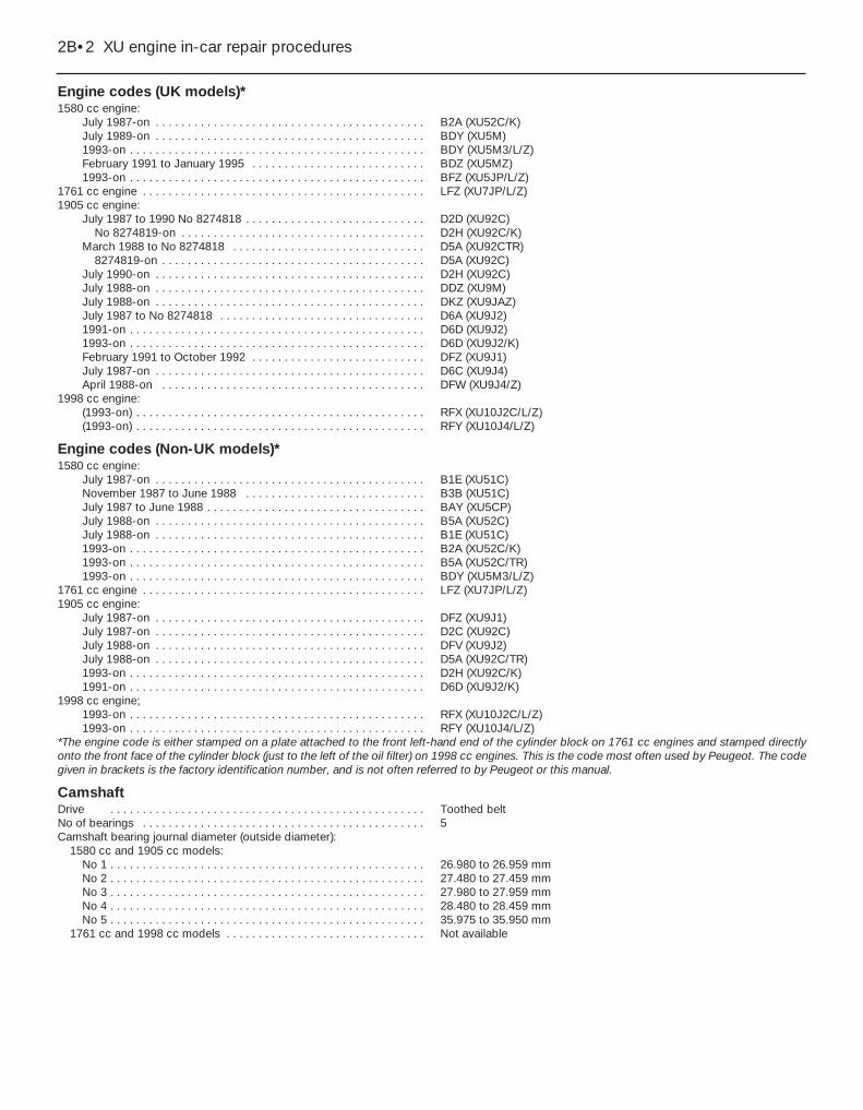
Engine codes (UK models)*1580 cc engine:
July 1987-on . . . . . . . . . . . . . . . . . . . . . . . . . . . . . . . . . . . . . . . . . . B2A (XU52C/K)July 1989-on . . . . . . . . . . . . . . . . . . . . . . . . . . . . . . . . . . . . . . . . . . BDY (XU5M)1993-on . . . . . . . . . . . . . . . . . . . . . . . . . . . . . . . . . . . . . . . . . . . . . . BDY (XU5M3/L/Z)February 1991 to January 1995 . . . . . . . . . . . . . . . . . . . . . . . . . . . BDZ (XU5MZ)1993-on . . . . . . . . . . . . . . . . . . . . . . . . . . . . . . . . . . . . . . . . . . . . . . BFZ (XU5JP/L/Z)
1761 cc engine . . . . . . . . . . . . . . . . . . . . . . . . . . . . . . . . . . . . . . . . . . . . LFZ (XU7JP/L/Z)1905 cc engine:
July 1987 to 1990 No 8274818 . . . . . . . . . . . . . . . . . . . . . . . . . . . . D2D (XU92C)No 8274819-on . . . . . . . . . . . . . . . . . . . . . . . . . . . . . . . . . . . . . . D2H (XU92C/K)
March 1988 to No 8274818 . . . . . . . . . . . . . . . . . . . . . . . . . . . . . . D5A (XU92CTR)8274819-on . . . . . . . . . . . . . . . . . . . . . . . . . . . . . . . . . . . . . . . . . D5A (XU92C)
July 1990-on . . . . . . . . . . . . . . . . . . . . . . . . . . . . . . . . . . . . . . . . . . D2H (XU92C)July 1988-on . . . . . . . . . . . . . . . . . . . . . . . . . . . . . . . . . . . . . . . . . . DDZ (XU9M)July 1988-on . . . . . . . . . . . . . . . . . . . . . . . . . . . . . . . . . . . . . . . . . . DKZ (XU9JAZ)July 1987 to No 8274818 . . . . . . . . . . . . . . . . . . . . . . . . . . . . . . . . D6A (XU9J2)1991-on . . . . . . . . . . . . . . . . . . . . . . . . . . . . . . . . . . . . . . . . . . . . . . D6D (XU9J2)1993-on . . . . . . . . . . . . . . . . . . . . . . . . . . . . . . . . . . . . . . . . . . . . . . D6D (XU9J2/K)February 1991 to October 1992 . . . . . . . . . . . . . . . . . . . . . . . . . . . DFZ (XU9J1)July 1987-on . . . . . . . . . . . . . . . . . . . . . . . . . . . . . . . . . . . . . . . . . . D6C (XU9J4)April 1988-on . . . . . . . . . . . . . . . . . . . . . . . . . . . . . . . . . . . . . . . . . DFW (XU9J4/Z)
1998 cc engine:(1993-on) . . . . . . . . . . . . . . . . . . . . . . . . . . . . . . . . . . . . . . . . . . . . . RFX (XU10J2C/L/Z)(1993-on) . . . . . . . . . . . . . . . . . . . . . . . . . . . . . . . . . . . . . . . . . . . . . RFY (XU10J4/L/Z)
Engine codes (Non-UK models)*1580 cc engine:
July 1987-on . . . . . . . . . . . . . . . . . . . . . . . . . . . . . . . . . . . . . . . . . . B1E (XU51C)November 1987 to June 1988 . . . . . . . . . . . . . . . . . . . . . . . . . . . . B3B (XU51C)July 1987 to June 1988 . . . . . . . . . . . . . . . . . . . . . . . . . . . . . . . . . . BAY (XU5CP)July 1988-on . . . . . . . . . . . . . . . . . . . . . . . . . . . . . . . . . . . . . . . . . . B5A (XU52C)July 1988-on . . . . . . . . . . . . . . . . . . . . . . . . . . . . . . . . . . . . . . . . . . B1E (XU51C)1993-on . . . . . . . . . . . . . . . . . . . . . . . . . . . . . . . . . . . . . . . . . . . . . . B2A (XU52C/K)1993-on . . . . . . . . . . . . . . . . . . . . . . . . . . . . . . . . . . . . . . . . . . . . . . B5A (XU52C/TR)1993-on . . . . . . . . . . . . . . . . . . . . . . . . . . . . . . . . . . . . . . . . . . . . . . BDY (XU5M3/L/Z)
1761 cc engine . . . . . . . . . . . . . . . . . . . . . . . . . . . . . . . . . . . . . . . . . . . . LFZ (XU7JP/L/Z)1905 cc engine:
July 1987-on . . . . . . . . . . . . . . . . . . . . . . . . . . . . . . . . . . . . . . . . . . DFZ (XU9J1)July 1987-on . . . . . . . . . . . . . . . . . . . . . . . . . . . . . . . . . . . . . . . . . . D2C (XU92C)July 1988-on . . . . . . . . . . . . . . . . . . . . . . . . . . . . . . . . . . . . . . . . . . DFV (XU9J2)July 1988-on . . . . . . . . . . . . . . . . . . . . . . . . . . . . . . . . . . . . . . . . . . D5A (XU92C/TR)1993-on . . . . . . . . . . . . . . . . . . . . . . . . . . . . . . . . . . . . . . . . . . . . . . D2H (XU92C/K)1991-on . . . . . . . . . . . . . . . . . . . . . . . . . . . . . . . . . . . . . . . . . . . . . . D6D (XU9J2/K)
1998 cc engine;1993-on . . . . . . . . . . . . . . . . . . . . . . . . . . . . . . . . . . . . . . . . . . . . . . RFX (XU10J2C/L/Z)1993-on . . . . . . . . . . . . . . . . . . . . . . . . . . . . . . . . . . . . . . . . . . . . . . RFY (XU10J4/L/Z)
*The engine code is either stamped on a plate attached to the front left-hand end of the cylinder block on 1761 cc engines and stamped directlyonto the front face of the cylinder block (just to the left of the oil filter) on 1998 cc engines. This is the code most often used by Peugeot. The codegiven in brackets is the factory identification number, and is not often referred to by Peugeot or this manual.
CamshaftDrive . . . . . . . . . . . . . . . . . . . . . . . . . . . . . . . . . . . . . . . . . . . . . . . . . Toothed beltNo of bearings . . . . . . . . . . . . . . . . . . . . . . . . . . . . . . . . . . . . . . . . . . . . 5Camshaft bearing journal diameter (outside diameter):
1580 cc and 1905 cc models:No 1 . . . . . . . . . . . . . . . . . . . . . . . . . . . . . . . . . . . . . . . . . . . . . . . . . 26.980 to 26.959 mmNo 2 . . . . . . . . . . . . . . . . . . . . . . . . . . . . . . . . . . . . . . . . . . . . . . . . . 27.480 to 27.459 mmNo 3 . . . . . . . . . . . . . . . . . . . . . . . . . . . . . . . . . . . . . . . . . . . . . . . . . 27.980 to 27.959 mmNo 4 . . . . . . . . . . . . . . . . . . . . . . . . . . . . . . . . . . . . . . . . . . . . . . . . . 28.480 to 28.459 mmNo 5 . . . . . . . . . . . . . . . . . . . . . . . . . . . . . . . . . . . . . . . . . . . . . . . . . 35.975 to 35.950 mm
1761 cc and 1998 cc models . . . . . . . . . . . . . . . . . . . . . . . . . . . . . . . Not available
2B•2 XU engine in-car repair procedures
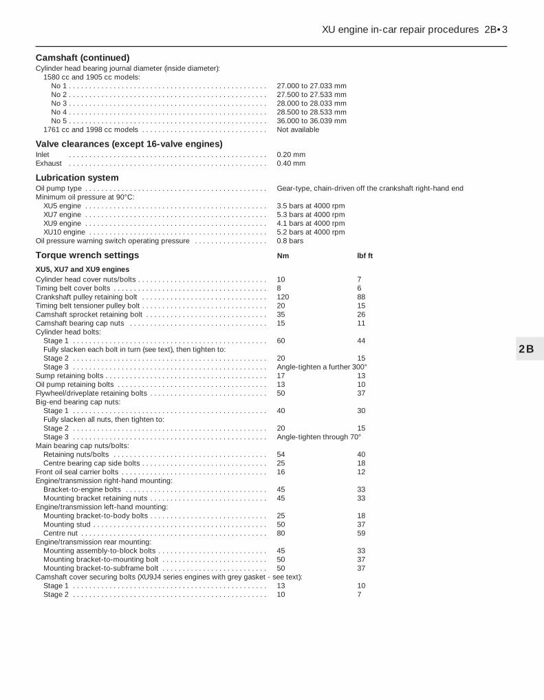
Camshaft (continued)Cylinder head bearing journal diameter (inside diameter):
1580 cc and 1905 cc models:No 1 . . . . . . . . . . . . . . . . . . . . . . . . . . . . . . . . . . . . . . . . . . . . . . . . . 27.000 to 27.033 mmNo 2 . . . . . . . . . . . . . . . . . . . . . . . . . . . . . . . . . . . . . . . . . . . . . . . . . 27.500 to 27.533 mmNo 3 . . . . . . . . . . . . . . . . . . . . . . . . . . . . . . . . . . . . . . . . . . . . . . . . . 28.000 to 28.033 mmNo 4 . . . . . . . . . . . . . . . . . . . . . . . . . . . . . . . . . . . . . . . . . . . . . . . . . 28.500 to 28.533 mmNo 5 . . . . . . . . . . . . . . . . . . . . . . . . . . . . . . . . . . . . . . . . . . . . . . . . . 36.000 to 36.039 mm
1761 cc and 1998 cc models . . . . . . . . . . . . . . . . . . . . . . . . . . . . . . . Not available
Valve clearances (except 16-valve engines)Inlet . . . . . . . . . . . . . . . . . . . . . . . . . . . . . . . . . . . . . . . . . . . . . . . . . 0.20 mmExhaust . . . . . . . . . . . . . . . . . . . . . . . . . . . . . . . . . . . . . . . . . . . . . . . . . 0.40 mm
Lubrication systemOil pump type . . . . . . . . . . . . . . . . . . . . . . . . . . . . . . . . . . . . . . . . . . . . . Gear-type, chain-driven off the crankshaft right-hand endMinimum oil pressure at 90°C:
XU5 engine . . . . . . . . . . . . . . . . . . . . . . . . . . . . . . . . . . . . . . . . . . . . . 3.5 bars at 4000 rpmXU7 engine . . . . . . . . . . . . . . . . . . . . . . . . . . . . . . . . . . . . . . . . . . . . . 5.3 bars at 4000 rpmXU9 engine . . . . . . . . . . . . . . . . . . . . . . . . . . . . . . . . . . . . . . . . . . . . . 4.1 bars at 4000 rpmXU10 engine . . . . . . . . . . . . . . . . . . . . . . . . . . . . . . . . . . . . . . . . . . . . 5.2 bars at 4000 rpm
Oil pressure warning switch operating pressure . . . . . . . . . . . . . . . . . . 0.8 bars
Torque wrench settings Nm lbf ft
XU5, XU7 and XU9 enginesCylinder head cover nuts/bolts . . . . . . . . . . . . . . . . . . . . . . . . . . . . . . . . 10 7Timing belt cover bolts . . . . . . . . . . . . . . . . . . . . . . . . . . . . . . . . . . . . . . 8 6Crankshaft pulley retaining bolt . . . . . . . . . . . . . . . . . . . . . . . . . . . . . . . 120 88Timing belt tensioner pulley bolt . . . . . . . . . . . . . . . . . . . . . . . . . . . . . . . 20 15Camshaft sprocket retaining bolt . . . . . . . . . . . . . . . . . . . . . . . . . . . . . . 35 26Camshaft bearing cap nuts . . . . . . . . . . . . . . . . . . . . . . . . . . . . . . . . . . 15 11Cylinder head bolts:
Stage 1 . . . . . . . . . . . . . . . . . . . . . . . . . . . . . . . . . . . . . . . . . . . . . . . . 60 44Fully slacken each bolt in turn (see text), then tighten to:Stage 2 . . . . . . . . . . . . . . . . . . . . . . . . . . . . . . . . . . . . . . . . . . . . . . . . 20 15Stage 3 . . . . . . . . . . . . . . . . . . . . . . . . . . . . . . . . . . . . . . . . . . . . . . . . Angle-tighten a further 300°
Sump retaining bolts . . . . . . . . . . . . . . . . . . . . . . . . . . . . . . . . . . . . . . . . 17 13Oil pump retaining bolts . . . . . . . . . . . . . . . . . . . . . . . . . . . . . . . . . . . . . 13 10Flywheel/driveplate retaining bolts . . . . . . . . . . . . . . . . . . . . . . . . . . . . . 50 37Big-end bearing cap nuts:
Stage 1 . . . . . . . . . . . . . . . . . . . . . . . . . . . . . . . . . . . . . . . . . . . . . . . . 40 30Fully slacken all nuts, then tighten to:Stage 2 . . . . . . . . . . . . . . . . . . . . . . . . . . . . . . . . . . . . . . . . . . . . . . . . 20 15Stage 3 . . . . . . . . . . . . . . . . . . . . . . . . . . . . . . . . . . . . . . . . . . . . . . . . Angle-tighten through 70°
Main bearing cap nuts/bolts:Retaining nuts/bolts . . . . . . . . . . . . . . . . . . . . . . . . . . . . . . . . . . . . . . 54 40Centre bearing cap side bolts . . . . . . . . . . . . . . . . . . . . . . . . . . . . . . . 25 18
Front oil seal carrier bolts . . . . . . . . . . . . . . . . . . . . . . . . . . . . . . . . . . . . 16 12Engine/transmission right-hand mounting:
Bracket-to-engine bolts . . . . . . . . . . . . . . . . . . . . . . . . . . . . . . . . . . . 45 33Mounting bracket retaining nuts . . . . . . . . . . . . . . . . . . . . . . . . . . . . . 45 33
Engine/transmission left-hand mounting:Mounting bracket-to-body bolts . . . . . . . . . . . . . . . . . . . . . . . . . . . . . 25 18Mounting stud . . . . . . . . . . . . . . . . . . . . . . . . . . . . . . . . . . . . . . . . . . . 50 37Centre nut . . . . . . . . . . . . . . . . . . . . . . . . . . . . . . . . . . . . . . . . . . . . . . 80 59
Engine/transmission rear mounting:Mounting assembly-to-block bolts . . . . . . . . . . . . . . . . . . . . . . . . . . . 45 33Mounting bracket-to-mounting bolt . . . . . . . . . . . . . . . . . . . . . . . . . . 50 37Mounting bracket-to-subframe bolt . . . . . . . . . . . . . . . . . . . . . . . . . . 50 37
Camshaft cover securing bolts (XU9J4 series engines with grey gasket - see text):Stage 1 . . . . . . . . . . . . . . . . . . . . . . . . . . . . . . . . . . . . . . . . . . . . . . . . 13 10Stage 2 . . . . . . . . . . . . . . . . . . . . . . . . . . . . . . . . . . . . . . . . . . . . . . . . 10 7
XU engine in-car repair procedures 2B•3
2B

Torque wrench settings (continued) Nm lbf ft
XU10 enginesCylinder head cover nuts/bolts . . . . . . . . . . . . . . . . . . . . . . . . . . . . . . . . 10 7Timing belt cover bolts . . . . . . . . . . . . . . . . . . . . . . . . . . . . . . . . . . . . . . 8 6Crankshaft pulley retaining bolt . . . . . . . . . . . . . . . . . . . . . . . . . . . . . . . 110 81Timing belt tensioner . . . . . . . . . . . . . . . . . . . . . . . . . . . . . . . . . . . . . . . 20 15Camshaft sprocket retaining bolt . . . . . . . . . . . . . . . . . . . . . . . . . . . . . . 35 26Camshaft bearing cap nuts/bolts . . . . . . . . . . . . . . . . . . . . . . . . . . . . . . 16 12Cylinder head bolts:
Stage 1 . . . . . . . . . . . . . . . . . . . . . . . . . . . . . . . . . . . . . . . . . . . . . . . . 35 26Stage 2 . . . . . . . . . . . . . . . . . . . . . . . . . . . . . . . . . . . . . . . . . . . . . . . . 70 52Stage 3 . . . . . . . . . . . . . . . . . . . . . . . . . . . . . . . . . . . . . . . . . . . . . . . . Angle-tighten through 160°
Sump retaining bolts . . . . . . . . . . . . . . . . . . . . . . . . . . . . . . . . . . . . . . . . 16 12Oil pump retaining bolts . . . . . . . . . . . . . . . . . . . . . . . . . . . . . . . . . . . . . 13 10Flywheel/driveplate retaining bolts . . . . . . . . . . . . . . . . . . . . . . . . . . . . . 50 37Big-end bearing cap nuts:
Stage 1 . . . . . . . . . . . . . . . . . . . . . . . . . . . . . . . . . . . . . . . . . . . . . . . . 40 30Fully slacken all nuts, then tighten to:Stage 2 . . . . . . . . . . . . . . . . . . . . . . . . . . . . . . . . . . . . . . . . . . . . . . . . 20 15Stage 3 . . . . . . . . . . . . . . . . . . . . . . . . . . . . . . . . . . . . . . . . . . . . . . . . Angle-tighten through 70°
Main bearing cap bolts . . . . . . . . . . . . . . . . . . . . . . . . . . . . . . . . . . . . . . 70 52Piston oil jet spray tube bolt . . . . . . . . . . . . . . . . . . . . . . . . . . . . . . . . . . 10 7Front oil seal carrier bolts . . . . . . . . . . . . . . . . . . . . . . . . . . . . . . . . . . . . 16 12Engine/transmission right-hand mounting:
Mounting bracket retaining nuts . . . . . . . . . . . . . . . . . . . . . . . . . . . . . 45 33Curved retaining plate . . . . . . . . . . . . . . . . . . . . . . . . . . . . . . . . . . . . . 20 15
Engine/transmission left-hand mounting:Mounting rubber-to-body bolts . . . . . . . . . . . . . . . . . . . . . . . . . . . . . 20 15Mounting stud . . . . . . . . . . . . . . . . . . . . . . . . . . . . . . . . . . . . . . . . . . . 50 37Centre nut . . . . . . . . . . . . . . . . . . . . . . . . . . . . . . . . . . . . . . . . . . . . . . 65 48
Engine/transmission rear mounting:Mounting assembly-to-block bolts . . . . . . . . . . . . . . . . . . . . . . . . . . . 45 33Mounting link-to-mounting bolt . . . . . . . . . . . . . . . . . . . . . . . . . . . . . 50 37Mounting link-to-subframe bolt . . . . . . . . . . . . . . . . . . . . . . . . . . . . . 70 52
2B•4 XU engine in-car repair procedures
1 General information
How to use this ChapterThis Part of Chapter 2 describes those
repair procedures that can reasonably becarried out on the XU series petrol engine,while it remains in the car. If the engine hasbeen removed from the car and is beingdismantled as described in Part C, anypreliminary dismantling procedures can beignored. Refer to Part A for information on theTU series petrol engine.
Note that, while it may be possiblephysically to overhaul items such as thepiston/connecting rod assemblies while theengine is in the car, such tasks are not usuallycarried out as separate operations. Usually,several additional procedures (not to mentionthe cleaning of components and oilways) haveto be carried out. For this reason, all suchtasks are classed as major overhaulprocedures, and are described in Part C ofthis Chapter.
Part C describes the removal of theengine/transmission from the vehicle, and thefull overhaul procedures that can then becarried out.
XU series engine descriptionThe XU series engine is a well-proven
engine which has been fitted to manyprevious Peugeot and Citroën vehicles. Theengine is of the in-line 4-cylinder type,mounted transversely at the front of the car.The clutch and transmission are attached toits left-hand end. The 405 range is availablewith 1580 cc (8-valve), 1761 cc (8-valve), 1905 cc (8- and 16-valve), and 1998 cc (8- and 16-valve) versions of the XU seriesengine. The 1905 cc and 1998 cc 16-valveengines are of the DOHC (double overheadcamshaft) type; all the others are SOHC(single overhead camshaft) engines.
The crankshaft runs in five main bearings.Thrustwashers are fitted to No 2 main bearingcap, to control crankshaft endfloat.
The connecting rods rotate on horizontally-split bearing shells at their big-ends. Thepistons are attached to the connecting rodsby gudgeon pins. On 16-valve models, thegudgeon pins are a sliding fit in theconnecting rod, and are secured with circlips.On all other models, they are an interferencefit in the connecting rod small-end eyes. Thealuminum alloy pistons have three rings - two compression rings and an oil control ring.
On 1580 cc, 1761 cc and 1905 cc (both 8-and 16-valve) models, the cylinder block is of
the “wet-liner” type. The cylinder block is castin aluminium alloy, and the bores havereplaceable cast-iron liners that are locatedfrom their top ends. Sealing O-rings are fittedat the base of each liner, to prevent theescape of coolant into the sump.
On all 1998 cc models (both 8- and 16-valve), the engine is of the conventional“dry-liner” type. The cylinder block is cast iniron, and no separate bore liners are fitted.
On 16-valve models, both inlet and exhaustcamshafts are driven by a toothed timing belt.The camshafts operate the sixteen valves viaself-adjusting hydraulic tappets (fitted to thecam followers), thus eliminating the need tomanually adjust the valve clearances. Bothcamshafts run in bearing caps which arebolted to the top of the cylinder head. Theinlet and exhaust valves are each closed bycoil springs, and operate in guides pressedinto the cylinder head.
On 8-valve models, the camshaft is drivenby a toothed timing belt, and it operates theeight valves via followers located beneatheach cam lobe. The valve clearances areadjusted by shims, positioned between thefollowers and the tip of the valve stem. Thecamshaft runs in bearing caps which arebolted to the top of the cylinder head. Theinlet and exhaust valves are each closed bycoil springs, and operate in guides pressed

into the cylinder head. Both the valve seatsand guides can be renewed separately ifworn.
On all models, the water pump is driven bythe timing belt.
Lubrication is by means of an oil pumpwhich is driven (via a chain and sprocket) offthe crankshaft right-hand end. It draws oilthrough a strainer located in the sump, andthen forces it through an externally-mountedfilter into galleries in the cylinderblock/crankcase. From there, the oil isdistributed to the crankshaft (main bearings)and camshaft. The big-end bearings aresupplied with oil via internal drillings in thecrankshaft; the camshaft bearings alsoreceive a pressurised supply. The camshaftlobes and valves are lubricated by splash, asare all other engine components. On 16-valvemodels, an oil cooler is mounted beneath theoil filter cartridge, to keep the oil temperatureconstant under severe operating conditions.The oil cooler is supplied with coolant fromthe engine cooling system.
Throughout the manual, it is oftennecessary to identify the engines not only bytheir cubic capacity, but also by their enginecode. The engine code consists of threeletters (eg. RFY). On 1.6, 1.8 and 1.9 litremodels the code is stamped on a plateattached to the front, left-hand end of thecylinder block, and on 2.0 litre models theengine code is stamped directly onto the frontface of the cylinder block, on the machinedsurface located just to the left of the oil filter(next to the crankcase vent hose union).
Repair operations possible withthe engine in the car
The following work can be carried out withthe engine in the car:a) Compression pressure - testing.b) Cylinder head cover - removal and
refitting.c) Crankshaft pulley - removal and refitting.d) Timing belt covers - removal and refitting.e) Timing belt - removal, refitting and
adjustment.f) Timing belt tensioner and sprockets -
removal and refitting.g) Camshaft oil seal(s) - renewal.h) Camshaft(s) and followers - removal,
inspection and refitting.i) Valve clearances - checking and
adjustment.j) Cylinder head - removal and refitting.k) Cylinder head and pistons -
decarbonising.l) Sump - removal and refitting.m)Oil pump - removal, overhaul and refitting.n) Crankshaft oil seals - renewal.o) Engine/transmission mountings -
inspection and renewal.p) Flywheel/driveplate - removal, inspection
and refitting.q) Oil cooler (1998 cc 16-valve models) -
removal and refitting.
2 Compression test
Refer to Chapter 2A, Section 2.
3 Engine assembly/valvetiming holes - generalinformation and usage
3Note: Do not attempt to rotate the enginewhilst the crankshaft/camshaft are locked inposition. If the engine is to be left in this statefor a long period of time, it is a good idea toplace suitable warning notices inside thevehicle, and in the engine compartment. Thiswill reduce the possibility of the engine beingaccidentally cranked on the starter motor,which is likely to cause damage with thelocking pins in place.1 On all models, timing holes are drilled in thecamshaft sprocket(s) and crankshaft pulley.The holes are used to align the crankshaft andcamshaft(s), to prevent the possibility of thevalves contacting the pistons when refittingthe cylinder head, or when refitting the timingbelt. When the holes are aligned with theircorresponding holes in the cylinder head andcylinder block (as appropriate), suitablediameter pins can be inserted to lock both thecamshaft and crankshaft in position,preventing them rotating unnecessarily.Proceed as follows.2 Remove the timing belt upper cover asdescribed in Section 6.3 Apply the handbrake, jack up the front ofthe car and support it on axle stands (see“Jacking and Vehicle Support”). Remove theright-hand front roadwheel.4 From underneath the front of the car, priseout the two retaining clips and remove theplastic cover from the wing valance, to gainaccess to the crankshaft pulley bolt. Wherenecessary, unclip the coolant hoses from thebracket, to improve access further. Thecrankshaft can then be turned using a suitablesocket and extension bar fitted to the pulleybolt. Note that the crankshaft must always beturned in a clockwise direction (viewed fromthe right-hand side of vehicle).
16-valve models5 Rotate the crankshaft pulley until the timingholes in both camshafts are aligned with theircorresponding holes in the cylinder head. Theholes are aligned when the inlet camshaftsprocket hole is in the 8 o’clock position, andthe exhaust camshaft sprocket is in the 6o’clock position, when viewed from the right-hand end of the engine.6 With the camshaft sprocket holes correctlypositioned, insert a 6 mm diameter bolt (or adrill of suitable size), through the timing hole inthe crankshaft pulley, and locate it in thecorresponding hole in the end of the cylinderblock. Note that it may be necessary to rotate
the crankshaft slightly, to get the holes toalign.7 With the crankshaft pulley locked inposition, insert a 6 mm diameter bolt (or a drill)through the timing hole in each camshaftsprocket, and locate it in the cylinder head.Note that the special Peugeot locking pins areactually 8 mm in diameter, with only their endsstepped down to 6 mm to locate in thecylinder head (see illustration). To simulatethis, wrap insulation tape around the outerend of the bolt or drill, to build it up until it is asnug fit in the camshaft hole.8 The crankshaft and camshafts are nowlocked in position, preventing unnecessaryrotation.
All other models9 Rotate the crankshaft pulley until the timinghole in the camshaft sprocket is aligned withits corresponding hole in the cylinder head.Note that the hole is aligned when thesprocket hole is in the 8 o’clock position,when viewed from the right-hand end of theengine.10 On early 1580 cc and 1905 cc modelshaving a semi-automatic timing belt tensioner,a 10 mm diameter bolt (or a drill of suitablesize) will be required to lock the crankshaftpulley in position.11 On later 1580 cc and 1905 cc models,and all 1761 and 1998 cc 8-valve models(which have a manually-adjusted timing belttensioner pulley) the pulley can be locked inposition with an 8 mm diameter bolt or drill.The special Peugeot locking pin is actually 10mm in diameter, with only its end steppeddown to 8 mm to locate in the cylinder block.To simulate this, wrap insulation tape aroundthe outer end of the bolt/drill, to build it upuntil it is a snug fit in the pulley hole.12 With the camshaft sprocket holescorrectly positioned, insert the required bolt ordrill through the timing hole in the crankshaftpulley, and locate it in the corresponding holein the end of the cylinder block. Note that itmay be necessary to rotate the crankshaftslightly, to get the holes to align.13 With the crankshaft pulley locked inposition, insert the appropriate bolt or drillthrough the timing hole in the camshaft
XU engine in-car repair procedures 2B•5
3.7 Camshaft sprocket locking pins inposition (arrowed) -
1998 cc 16-valve models
2B

sprocket and locate it in the cylinder head(see illustration).14 The crankshaft and camshaft are nowlocked in position, preventing rotation.
4 Cylinder head cover -removal and refitting 2
Removal1 Disconnect the battery negative lead.
1580 cc and 1905 cc (8-valve) models2 On 1580 cc models, remove the air cleaner-to-throttle body duct, and the air cleanerhousing, as described in Chapter 4.3 On 1905 cc models, remove the air cleanerhousing as described in Chapter 4, andposition the inlet duct clear of the cylinderhead cover.4 On all models, slacken the retaining clipand disconnect the breather hose from thetop of the cylinder head cover. Where theoriginal crimped-type hose clip is still fitted,cut it off and discard it. Replace it with astandard worm-drive hose clip on refitting.5 Undo the two nuts/bolts securing the HTlead retaining bracket to the cylinder head,and position the bracket clear of the headcover (see illustration).6 Slacken and remove the two remainingcylinder head cover retaining bolts, along withtheir sealing washers.
7 Lift off the cylinder head cover, and removeit along with its rubber seal. Examine the sealfor signs of damage and deterioration, and ifnecessary, renew it. Also examine theretaining bolt sealing washers for signs ofdamage, and renew if required.
1761 cc and 1998 cc (8-valve) models8 Slacken the retaining clips, and disconnectthe breather hoses from the front right-handend of the cover. Where the original crimped-type hose clips are still fitted, cut them off anddiscard them; use standard worm-drive hoseclips on refitting.9 Slacken the retaining clip, and disconnectthe air cleaner-to-throttle housing duct fromthe front of the cylinder head cover. Alsoremove the inlet duct from the left-hand sideof the head cover.10 Release the two retaining clips, then undothe two retaining screws located at the front,and remove the air cleaner element coverfrom the cylinder head cover. Remove the aircleaner element, and store it with the cover.11 Slacken and remove the ten cylinder headcover retaining nuts, lift off the cylinder headcover, and remove it along with its rubber seal(see illustration). Examine the seal for signsof damage and deterioration, and ifnecessary, renew it.
16-valve models12 Refer to the information given in Chapter 4 on depressurising the fuel system.Slacken the retaining clips, and disconnectthe fuel feed and return hoses from theirunions at the front of the head cover. Wherethe original crimped-type hose clips are stillfitted, cut them off and discard them; usestandard worm-drive hose clips on refitting.Plug both the hose and fuel rail ends, toprevent the possible entry of dirt into the fuelsystem. Mop up any spilt fuel.13 Undo the retaining nut and bolt securingthe fuel hose retaining clips to the top of thecylinder head cover, and remove both clips.Position both fuel hoses clear of the headcover, so that they do not hinder the removalprocedure.14 Slacken and remove the remaining sevenretaining bolts, and lift the spark plug accesscover off the cylinder head cover.
15 Pull each ignition HT coil off its sparkplug. Trace the coil wiring back to itsconnector on the left-hand end of the cylinderhead. Rotate the locking ring anti-clockwise,disconnect it from the main wiring loom, andremove the wiring and coils as an assembly.16 Disconnect the breather hose from theleft-hand end of the cylinder head. Anyoriginal crimped-type hose clips can bediscarded, as already mentioned.17 Slacken and remove the twelve cylinderhead cover retaining bolts, noting the correctfitted positions of any brackets or clips. Notethat the bolts are of four different lengths, andit is important that each is refitted in thecorrect position. To avoid confusion onrefitting, remove each bolt in turn, and store itin its correct fitted position by pushing itthrough a clearly-marked cardboard template.18 Lift off the cylinder head cover, andremove it along with its rubber seal. Recoverthe four spark plug hole sealing rings from thecylinder head. Examine all seals for damageand deterioration, and renew as necessary.
Refitting
1580 cc and 1905 cc models19 Carefully clean the cylinder head andcover mating surfaces, and remove all tracesof oil.20 Fit the rubber seal over the edge of thecylinder head cover, ensuring that it iscorrectly located along its entire length.21 Carefully refit the cylinder head cover tothe engine, taking great care not to displacethe rubber seal.22 Check that the seal is correctly located,then refit the cover retaining bolts and sealingwashers (not forgetting to position the HT leadbracket under the centre bolt head), andtighten them to the specified torque.23 Refit the remaining HT lead bracketretaining bolt, and tighten it securely.24 Reconnect the breather hose to thecylinder head cover, and securely tighten itsretaining clip.25 Refit the air cleaner housing and duct asdescribed in Chapter 4, and reconnect thebattery negative terminal.
1761 cc and 1998 cc 8-valve models26 Clean the cylinder head and cover matingsurfaces, and remove all traces of oil.27 Locate the rubber seal in the covergroove, ensuring that it is correctly locatedalong its entire length.28 Carefully refit the cylinder head cover tothe engine, taking great care not to displacethe rubber seal.29 Check that the seal is correctly located,then refit the cover retaining nuts, and tightenthem evenly and progressively to thespecified torque in the order shown (seeillustration).30 Refit the air cleaner element, and installthe element cover. Securely tighten the coverretaining screws, and secure it in position withthe retaining clips.
2B•6 XU engine in-car repair procedures
3.13 Camshaft sprocket and crankshaftpulley locking pins in position
(1580 cc model shown)
4.11 Cylinder head cover retaining nuts(arrowed) - 1761 cc and 1998 cc (8-valve) models
4.5 On 1580 cc and 1905 cc models, undothe retaining bolts/nuts and move the HT
lead retaining clips clear of the head cover
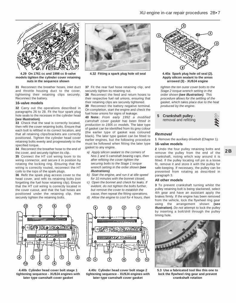
31 Reconnect the breather hoses, inlet ductand throttle housing duct to the cover,tightening their retaining clips securely.Reconnect the battery.
16-valve models32 Carry out the operations described inparagraphs 26 to 28. Fit the four spark plughole seals to the recesses in the cylinder head(see illustration).33 Check that the seal is correctly located,then refit the cover retaining bolts. Ensure thateach bolt is refitted in its correct location, andthat all retaining clips/brackets are correctlypositioned. Tighten the cylinder head coverretaining bolts evenly and progressively to thespecified torque.34 Reconnect the breather hose to the end ofthe cover, and securely tighten its clip.35 Connect the HT coil wiring loom to itswiring connector, and secure it in position byrotating the locking ring. Ensuring that thewiring is correctly routed, reconnect the HTcoils to the tops of the spark plugs.36 Refit the spark plug access cover to thehead cover, and refit its retaining bolts (notforgetting the fuel hose retaining clip). Ensurethat the HT coil wiring is correctly located inthe cover cutout, and that the fuel hoses arepositioned under the retaining clip, thensecurely tighten the retaining bolts.
37 Fit the rear fuel hose retaining clip, andsecurely tighten its retaining nut.38 Reconnect the feed and return hoses totheir respective fuel rail unions, ensuring thattheir retaining clips are securely tightened.39 Reconnect the battery negative terminal.On completion, start the engine and check thefuel hose unions for signs of leakage.40 Note: From early 1992 a modifiedcamshaft cover gasket has been fitted inproduction to 1905 cc models. The later typeof gasket can be identified from its grey colour(the earlier type of gasket was colouredblack). The later type gasket can be fitted toearlier engines, but the following proceduremust be followed when fitting the later typegasket to any engine.
a) Apply silicon sealant to the corners ofNos 1 and 5 camshaft bearing caps, thenafter refitting the cover tighten thesecuring bolts to the Stage 1 torquewrench setting in the order shown (seeillustrations).
b) Start the engine, and run it at idle speedfor 10 minutes with the bonnet closed.
c) Open the bonnet and check for leaks. Ifevident, do not tighten the bolts further,but remove the cover to establish thecause, then repeat the fitting operations.
d) Allow the engine to cool for 4 hours, then
tighten the ten outer cover bolts to theStage 2 torque wrench setting in theorder shown (see illustration). Thisprocedure allows for the settling of thegasket, which takes place due to the heatproduced by the engine.
5 Crankshaft pulley -removal and refitting 3
Removal1 Remove the auxiliary drivebelt (Chapter 1).
16-valve models2 Undo the four pulley retaining bolts andremove the pulley from the end of thecrankshaft, noting which way around it isfitted. If the pulley locating roll pin is a loosefit, remove it and store it with the pulley forsafe-keeping. If necessary, the pulley can beprevented from rotating as described inparagraph 3.
All other models3 To prevent crankshaft turning whilst thepulley retaining bolt is being slackened, select4th gear and have an assistant apply thebrakes firmly. If the engine has been removedfrom the vehicle, lock the flywheel ring gearusing the arrangement shown (seeillustration). Do not attempt to lock the pulleyby inserting a bolt/drill through the pulleytiming hole.
XU engine in-car repair procedures 2B•7
4.40a Spark plug hole oil seal (2). Apply silicon sealant to the areas
arrowed (3) - XU9J4 engine
5.3 Use a fabricated tool like this one tolock the flywheel ring gear and prevent
crankshaft rotation
4.40c Cylinder head cover bolt stage 2tightening sequence - XU9J4 engines with
later type camshaft cover gasket
4.40b Cylinder head cover bolt stage 1tightening sequence - XU9J4 engines with
later type camshaft cover gasket
4.32 Fitting a spark plug hole oil seal4.29 On 1761 cc and 1998 cc 8-valvemodels tighten the cylinder cover retaining
nuts in the sequence shown
2B

4 Unscrew the retaining bolt and washer,then slide the pulley off the end of thecrankshaft. If the pulley locating roll pin orWoodruff key (as applicable) is a loose fit,remove it and store it with the pulley for safe-keeping.
Refitting
16-valve models5 Ensure that the locating roll pin is inposition in the crankshaft. Offer up the pulley,ensuring that it is the correct way round.Locate the pulley on the roll pin, then refit theretaining bolts and tighten them to thespecified torque. If necessary, prevent thepulley from rotating as described in paragraph3.6 Refit and tension the auxiliary drivebelt asdescribed in Chapter 1.
All other models7 Ensure that the Woodruff key is correctlylocated in its crankshaft groove, or that theroll pin is in position (as applicable). Refit thepulley to the end of the crankshaft, aligning itslocating groove or hole with the Woodruff keyor pin.8 Thoroughly clean the threads of the pulleyretaining bolt, then apply a coat of lockingcompound to the bolt threads.9 Refit the crankshaft pulley retaining boltand washer. Tighten the bolt to the specifiedtorque, preventing the crankshaft from turningusing the method employed on removal.10 Refit and tension the auxiliary drivebelt asdescribed in Chapter 1.
6 Timing belt covers - removaland refitting 2
1580 cc and 1905 cc 8-valve models
Upper cover1 Release the retaining clips, and free the fuelhoses from the top of the cover.2 Undo the two cover retaining bolts (situatedat the base of the cover), and remove thecover from the engine compartment.
Centre cover - early (pre-1992)models with a semi-automatic belttensioner3 Slacken and remove the four coverretaining nuts and bolts (two directly belowthe mounting bracket, and two at the base ofthe cover), then manoeuvre the coverupwards out of the engine compartment.
Centre cover - later (1992-on) modelswith a manually-adjusted belttensioner pulley4 Slacken and remove the two cover retainingbolts (located directly beneath the mountingbracket). Move the cover upwards to free itfrom the two locating pins situated at the base
of the cover, and remove it from the enginecompartment.
Lower cover5 Remove the crankshaft pulley as describedin Section 5.6 Remove the centre cover as describedabove.7 On early models, undo the three lowercover retaining bolts and remove the coverfrom the engine.8 On later models, undo the two coverretaining bolts and remove the cover from theengine.
Lower (inner) cover - early (pre-1992)models with a semi-automatic belttensioner9 Remove the timing belt as described inSection 7.10 Slacken and remove the remaining bolts,noting their correct fitted positions, andremove the cover from the end of the cylinderblock.
1761 cc models
Upper cover11 Proceed as described in paragraphs 1and 2.
Centre cover12 Proceed as described in paragraph 4.
Lower cover13 Remove the crankshaft pulley asdescribed in Section 5.14 Remove the centre cover as described inparagraph 4.15 Undo the two cover retaining bolts, andremove the cover from the engine.
1905 cc 16-valve models
Upper cover16 Release the quick release clips from thetiming belt cover.17 Unscrew the upper cover securing screwsand withdraw the cover.
Lower cover18 Remove the crankshaft pulley asdescribed in Section 5.19 Unscrew the lower cover securing screwsand withdraw the cover.
1998 cc 8-valve models
Upper cover20 Release the retaining clip, and free thefuel hoses from the top of the timing beltcover.21 Slacken and remove the two coverretaining bolts, then lift the upper coverupwards and out of the engine compartment.
Lower cover22 Remove the crankshaft pulley asdescribed in Section 5.23 Slacken and remove the three retainingbolts, then remove the lower timing belt coverfrom the engine.
1998 cc 16-valve modelsUpper (outer) cover24 Undo the two upper retaining boltssecuring the outer cover to the inner cover.Slide the cover retaining clip upwards torelease it from its fasteners (see illustration).25 Ease the outer cover away from theengine. Lift it upwards, freeing it from itslocating bolts at the base of the cover, andout of the engine compartment.
Lower cover26 Remove the crankshaft pulley (Section 5).27 Remove the upper (outer) cover asdescribed above.28 Slacken and remove the two upper coverlower locating bolts, along with their spacers.Undo the two lower cover retaining bolts, andremove the cover from the engine.
Upper (inner) cover29 Remove the timing belt (see Section 7).30 Remove both camshaft sprockets asdescribed in Section 8.31 Undo the six bolts securing the cover tothe side of the cylinder head, and remove thecover from the engine.
Refitting32 Refitting is a reversal of the relevantremoval procedure, ensuring each coversection is correctly located, and the covernuts and/or bolts are correctly tightened.
7 Timing belt - generalinformation, removal andrefitting
4Note: Peugeot specify the use of a specialelectronic tool (SEEM C.TRONIC belttensioning measuring tool) to correctly set thetiming belt tension on all 1992-on models. Ifaccess to this equipment cannot be obtained,an approximate setting can be achieved usingthe method described below. In this case, thetension must be checked using the specialelectronic tool at the earliest opportunity. Donot drive the vehicle over large distances, oruse high engine speeds, until the belt tension isknown to be correct. Refer to a Peugeot dealerfor advice.
2B•8 XU engine in-car repair procedures
6.24 Timing belt upper (outer) coverretaining clip (arrowed) - 1998 cc 16-valve models
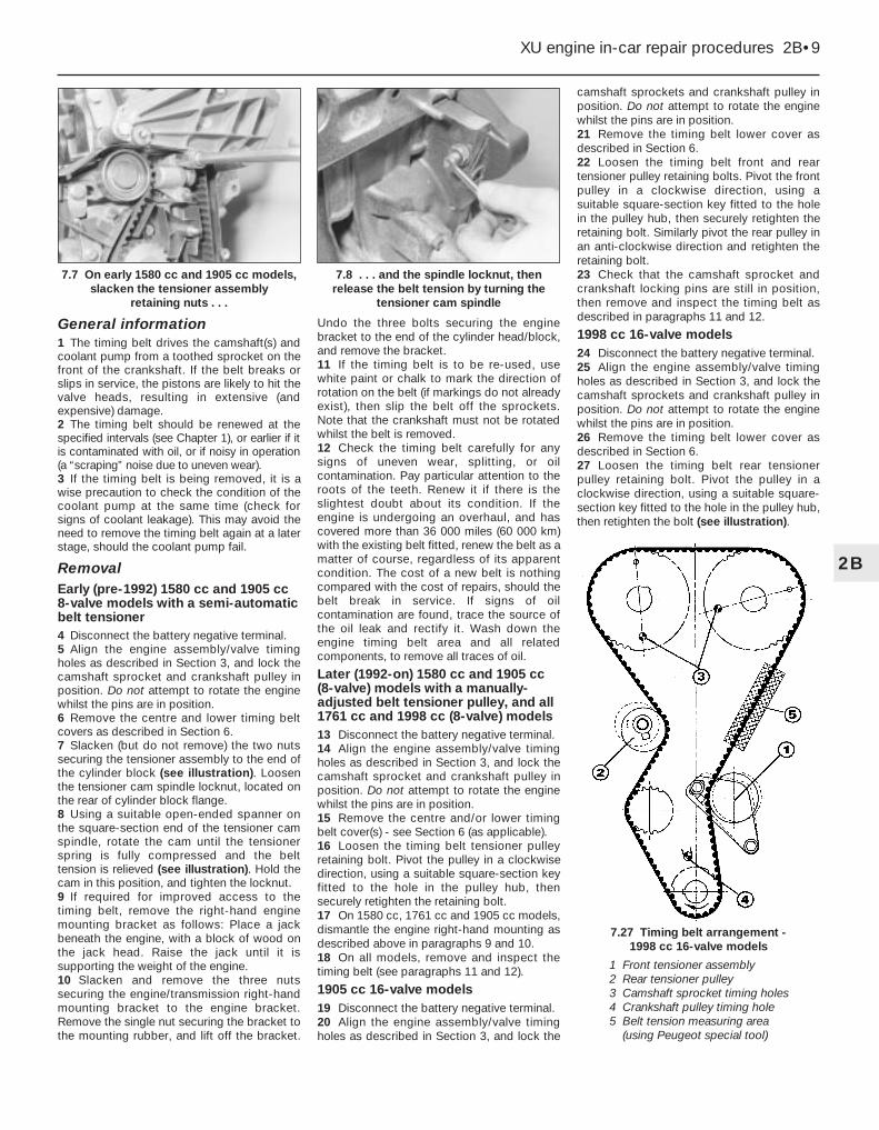
General information1 The timing belt drives the camshaft(s) andcoolant pump from a toothed sprocket on thefront of the crankshaft. If the belt breaks orslips in service, the pistons are likely to hit thevalve heads, resulting in extensive (andexpensive) damage.2 The timing belt should be renewed at thespecified intervals (see Chapter 1), or earlier if itis contaminated with oil, or if noisy in operation(a “scraping” noise due to uneven wear).3 If the timing belt is being removed, it is awise precaution to check the condition of thecoolant pump at the same time (check forsigns of coolant leakage). This may avoid theneed to remove the timing belt again at a laterstage, should the coolant pump fail.
RemovalEarly (pre-1992) 1580 cc and 1905 cc8-valve models with a semi-automaticbelt tensioner4 Disconnect the battery negative terminal.5 Align the engine assembly/valve timingholes as described in Section 3, and lock thecamshaft sprocket and crankshaft pulley inposition. Do not attempt to rotate the enginewhilst the pins are in position.6 Remove the centre and lower timing beltcovers as described in Section 6.7 Slacken (but do not remove) the two nutssecuring the tensioner assembly to the end ofthe cylinder block (see illustration). Loosenthe tensioner cam spindle locknut, located onthe rear of cylinder block flange.8 Using a suitable open-ended spanner onthe square-section end of the tensioner camspindle, rotate the cam until the tensionerspring is fully compressed and the belttension is relieved (see illustration). Hold thecam in this position, and tighten the locknut.9 If required for improved access to thetiming belt, remove the right-hand enginemounting bracket as follows: Place a jackbeneath the engine, with a block of wood onthe jack head. Raise the jack until it issupporting the weight of the engine.10 Slacken and remove the three nutssecuring the engine/transmission right-handmounting bracket to the engine bracket.Remove the single nut securing the bracket tothe mounting rubber, and lift off the bracket.
Undo the three bolts securing the enginebracket to the end of the cylinder head/block,and remove the bracket.11 If the timing belt is to be re-used, usewhite paint or chalk to mark the direction ofrotation on the belt (if markings do not alreadyexist), then slip the belt off the sprockets.Note that the crankshaft must not be rotatedwhilst the belt is removed.12 Check the timing belt carefully for anysigns of uneven wear, splitting, or oilcontamination. Pay particular attention to theroots of the teeth. Renew it if there is theslightest doubt about its condition. If theengine is undergoing an overhaul, and hascovered more than 36 000 miles (60 000 km)with the existing belt fitted, renew the belt as amatter of course, regardless of its apparentcondition. The cost of a new belt is nothingcompared with the cost of repairs, should thebelt break in service. If signs of oilcontamination are found, trace the source ofthe oil leak and rectify it. Wash down theengine timing belt area and all relatedcomponents, to remove all traces of oil.
Later (1992-on) 1580 cc and 1905 cc(8-valve) models with a manually-adjusted belt tensioner pulley, and all1761 cc and 1998 cc (8-valve) models13 Disconnect the battery negative terminal.14 Align the engine assembly/valve timingholes as described in Section 3, and lock thecamshaft sprocket and crankshaft pulley inposition. Do not attempt to rotate the enginewhilst the pins are in position.15 Remove the centre and/or lower timingbelt cover(s) - see Section 6 (as applicable).16 Loosen the timing belt tensioner pulleyretaining bolt. Pivot the pulley in a clockwisedirection, using a suitable square-section keyfitted to the hole in the pulley hub, thensecurely retighten the retaining bolt.17 On 1580 cc, 1761 cc and 1905 cc models,dismantle the engine right-hand mounting asdescribed above in paragraphs 9 and 10.18 On all models, remove and inspect thetiming belt (see paragraphs 11 and 12).
1905 cc 16-valve models19 Disconnect the battery negative terminal.20 Align the engine assembly/valve timingholes as described in Section 3, and lock the
camshaft sprockets and crankshaft pulley inposition. Do not attempt to rotate the enginewhilst the pins are in position.21 Remove the timing belt lower cover asdescribed in Section 6.22 Loosen the timing belt front and reartensioner pulley retaining bolts. Pivot the frontpulley in a clockwise direction, using asuitable square-section key fitted to the holein the pulley hub, then securely retighten theretaining bolt. Similarly pivot the rear pulley inan anti-clockwise direction and retighten theretaining bolt.23 Check that the camshaft sprocket andcrankshaft locking pins are still in position,then remove and inspect the timing belt asdescribed in paragraphs 11 and 12.
1998 cc 16-valve models24 Disconnect the battery negative terminal.25 Align the engine assembly/valve timingholes as described in Section 3, and lock thecamshaft sprockets and crankshaft pulley inposition. Do not attempt to rotate the enginewhilst the pins are in position.26 Remove the timing belt lower cover asdescribed in Section 6.27 Loosen the timing belt rear tensionerpulley retaining bolt. Pivot the pulley in aclockwise direction, using a suitable square-section key fitted to the hole in the pulley hub,then retighten the bolt (see illustration).
XU engine in-car repair procedures 2B•9
7.27 Timing belt arrangement - 1998 cc 16-valve models
7.8 . . . and the spindle locknut, thenrelease the belt tension by turning the
tensioner cam spindle
7.7 On early 1580 cc and 1905 cc models,slacken the tensioner assembly
retaining nuts . . .
2B
1 Front tensioner assembly2 Rear tensioner pulley3 Camshaft sprocket timing holes4 Crankshaft pulley timing hole5 Belt tension measuring area
(using Peugeot special tool)

28 Loosen the two front tensioner assemblyretaining bolts. Move the tensioner pulleyaway from the belt, using the same square-section key on the pulley backplate.29 Check that the camshaft sprocket andcrankshaft locking pins are still in position,then remove and inspect the timing belt asdescribed in paragraphs 11 and 12.
Refitting
Early (pre-1992) 1580 cc and 1905 ccmodels with a semi-automatic belttensioner30 Before refitting, thoroughly clean thetiming belt sprockets. Check that thetensioner pulley rotates freely, without anysign of roughness. If necessary, renew thetensioner pulley as described in Section 8.31 Ensure that the camshaft sprocket lockingpin is still in position. Temporarily refit thecrankshaft pulley, and insert the locking pinthrough the pulley timing hole to ensure thatthe crankshaft is still correctly positioned.32 Remove the crankshaft pulley. Manoeuvrethe timing belt into position, ensuring that anyarrows on the belt are pointing in the directionof rotation (clockwise when viewed from theright-hand end of the engine).33 Do not twist the timing belt sharply whilerefitting it. Fit the belt over the crankshaft andcamshaft sprockets. Ensure that the belt“front run” is taut - ie, any slack should be onthe tensioner pulley side of the belt. Fit thebelt over the water pump sprocket andtensioner pulley. Ensure that the belt teeth areseated centrally in the sprockets.34 Slacken the tensioner cam spindlelocknut, and check that the tensioner pulley isforced against the timing belt by springpressure.35 Refit the crankshaft pulley, tightening itsretaining bolt by hand only.36 Rotate the crankshaft through at least twocomplete rotations in a clockwise direction(viewed from the right-hand end of theengine). Realign the camshaft and crankshaftengine assembly/valve timing holes (seeSection 3). Do not at any time rotate thecrankshaft anti-clockwise. Both camshaft andcrankshaft timing holes should be aligned sothat the locking pins can be easily inserted.This indicates that the valve timing is correct.37 If the timing holes are not correctlypositioned, release the tensioner assembly asdescribed in paragraph 8, and disengage thebelt from the camshaft sprocket. Rotate thecamshaft and crankshaft slightly as requireduntil both locking pins are in position.Relocate the timing belt on the camshaftsprocket. Ensure that the belt “front run” istaut - ie, that any slack is on the tensionerpulley side of the belt. Slacken the tensionerlocknut, then remove the locking pins andrepeat the procedure in paragraph 36.38 Once both timing holes are correctlyaligned, tighten the two tensioner assemblyretaining nuts to the specified torque. Tighten
the tensioner cam spindle locknut to itsspecified torque.39 With the belt correctly installed andtensioned, where removed refit the enginebracket to the side of the cylinder head/block,and securely tighten its retaining bolts. Refitthe right-hand mounting bracket, and tightenits retaining nuts to the specified torque. Thejack can then be removed from underneaththe engine.40 Remove the crankshaft pulley, then refitthe timing belt covers (refer to Section 6).41 Install the crankshaft pulley (Section 5),and reconnect the battery negative terminal.
Later (1992-on) 1580 cc and 1905 cc(8-valve) models with a manually-adjusted belt tensioner pulley, and all1761 cc and 1998 cc (8-valve) modelsNote: Peugeot specify the use of a specialelectronic tool (SEEM C. TRONIC belt tensionmeasuring tool) to correctly set the timing belttension. If this equipment is not available, anapproximate setting can be achieved usingthe method described below. If this method isused, however, the belt tension must bechecked using the special electronic tool atthe earliest possible opportunity. Do not drivethe vehicle over large distances, or use highengine speeds, until the belt tension is knownto be correct. Refer to a Peugeot dealer foradvice.42 Install the timing belt as described abovein paragraphs 30 to 33.43 Loosen the tensioner pulley retaining bolt.Using the square-section key, pivot the pulleyanti-clockwise to remove all free play from thetiming belt.44 If the special belt tension measuringequipment is available, it should be fitted tothe “front run” of the timing belt. The tensionerroller should be adjusted so that the initial belttension is 16 ± 2 units on 1998 cc 8-valvemodels, and 30 ± 2 units on all other models.45 Tighten the pulley retaining bolt to thespecified torque. Refit the crankshaft pulleyagain, tightening its bolt by hand only.46 Carry out the operations described inparagraph 36 (and where necessary, para-graph 37, ignoring the information about thetensioner) to ensure both timing holes arecorrectly aligned and the valve timing is correct.47 If the tension is being set without usingthe special measuring tool, proceed asfollows. Check that, under moderate pressurefrom the thumb and forefinger, the belt canjust be twisted through 90° at the mid-point ofthe “front run” of the belt. Note that thismethod is only an initial setting, and the belttension must checked at the earliest availableopportunity using the special measuring tool.Failure to do so could lead to the beltbreaking (through over-tightening) or slipping(through slackness), resulting in seriousengine damage. If necessary, readjust thetensioner pulley position as required. Tightenits retaining bolt to the specified torque oncompletion.
48 If the special measuring tool is beingused, the final belt tension on the “front run”of the belt on all models should be 44 ± 2units. Readjust the tensioner pulley positionas required, then retighten the retaining bolt tothe specified torque. Rotate the crankshaftthrough a further two rotations clockwise, andrecheck the tension. Repeat this procedure asnecessary until the correct tension reading isobtained after rotating the crankshaft.49 With the belt tension correctly set, on1580 cc, 1761 cc and 1905 cc models, whereremoved refit the engine bracket to the side ofthe cylinder head/block, and securely tightenits retaining bolts. Refit the right-hand enginemounting bracket, and tighten its retainingnuts to the specified torque. The jack can thenbe removed from underneath the engine.50 On all models, remove the crankshaftpulley, then refit the timing belt cover(s) asdescribed in Section 6.51 Refit the crankshaft pulley (Section 5), andreconnect the battery negative terminal.
1905 cc 16-valve modelsNote: Peugeot specify the use of a specialelectronic tool (SEEM belt tension measuringtool) to correctly set the timing belt tension. Ifthis equipment is not available, anapproximate setting can be achieved usingthe method described below. If this method isused, however, the tension must be checkedusing the special electronic tool at the earliestpossible opportunity. Do not drive the vehicleover large distances, or use high enginespeeds, until the belt tension is known to becorrect. Refer to a Peugeot dealer for advice.52 Before refitting, thoroughly clean thetiming belt sprockets. Check that eachtensioner pulley rotates freely, without anysign of roughness. If necessary, renew thetensioner pulley(s) as described in Section 8.53 Ensure that the camshaft and crankshaftsprocket locking pins are still in position.Slacken both tensioner mounting bolts so thatthey are free to pivot easily.54 Manoeuvre the timing belt into position,ensuring that any arrows on the belt arepointing in the direction of rotation (clockwisewhen viewed from the right-hand end of theengine). Fit the timing belt in the sequencegiven in the accompanying illustration (seeillustration).
2B•10 XU engine in-car repair procedures
7.54 Fit the timing belt in the sequencegiven - 1905 cc 16-valve engines

55 Note that there may be timing marks onthe belt, in the form of yellow lines, to ensure itis correctly positioned on both camshaftsprockets and the crankshaft sprocket. Thetwo single-line timing marks should be alignedwith the timing dot (directly opposite thesprocket timing hole) on each camshaftsprocket. The double-line timing mark shouldbe aligned with the crankshaft sprocket,where it will be directly opposite the sprocketWoodruff key slot. Peugeot state that the useof these timing marks is optional, but they areuseful in helping to ensure that the valvetiming is correctly set at the first attempt.56 With the three locking pins in position,move both the front and rear tensioner pulleystowards the timing belt until both pulleys arecontacting the belt. Securely tighten theretaining bolts.57 If the tension is being set without the useof the special measuring tool, proceed asfollows. Using the square-section key fitted tothe hole in the tensioner backplate, move thefront tensioner pulley against the belt until allfree play is removed from the belt. Hold thetensioner in this position, and tighten thepulley retaining bolts to the specified torque.Similarly move the rear tensioner pulleyagainst the belt and tighten the bolt.58 If the special belt tension measuringequipment is available, it should be fitted tothe “front run” of the timing belt, between thefront tensioner and the camshaft sprocket.Move the front tensioner pulley anti-clockwiseso that the belt is tensioned to a setting of 19units, then tighten the retaining bolt to thespecified torque setting.59 Slacken the rear tensioner pulley retainingbolt. Using the square-section key, pivot thepulley clockwise until the belt tension on the“front run” is 21 units. Hold the tensioner inposition, and tighten its retaining bolt to thespecified torque setting.60 Remove the locking pins from thecamshaft and crankshaft sprockets and,where fitted, the tensioning measuring devicefrom the belt.61 Rotate the crankshaft through at least twocomplete rotations in a clockwise direction(viewed from the right-hand end of theengine). Realign the camshaft and crankshaftengine assembly/valve timing holes (seeSection 3). Do not at any time rotate thecrankshaft anti-clockwise. Both camshafttiming holes and the crankshaft timing holeshould be correctly positioned so that thelocking pins can be easily inserted, indicatingthat the valve timing is correct.62 If the timing holes are not correctlypositioned, repeat the tensioning procedure.63 Once the valve timing is correctly set,remove the locking pins and recheck the belttension.64 If the tension is being set without thespecial measuring tool, proceed as follows.Check that, under moderate pressure fromthe thumb and forefinger, the belt can just betwisted through 45°, at the mid-point between
the camshaft sprocket and tensioner pulley onthe “front run” of the belt. Note that thismethod is only an initial setting, and the belttension must be checked at the earliestavailable opportunity using the specialmeasuring tool. Failure to do so could lead tothe belt breaking (through over-tightening) orslipping (through slackness), resulting inserious engine damage.65 If the special measuring tool is beingused, the final belt tension on the “front run”of the belt, between the camshaft sprocketand tensioner pulley, should be 45 ± 5 units.Repeat the procedure as necessary, until thecorrect tension reading is obtained after thecrankshaft has been rotated.66 Once the belt tension is correctly set, refitthe timing belt covers as described in Section 6. Refit the crankshaft pulley asdescribed in Section 5, and reconnect thebattery negative terminal
1998 cc 16-valve modelsNote: Peugeot specify the use of a specialelectronic tool (SEEM belt tension measuringtool) to correctly set the timing belt tension. Ifthis equipment is not available, anapproximate setting can be achieved usingthe method described below. If this method isused, however, the tension must be checkedusing the special electronic tool at the earliestpossible opportunity. Do not drive the vehicleover large distances, or use high enginespeeds, until the belt tension is known to becorrect. Refer to a Peugeot dealer for advice.67 Before refitting, thoroughly clean thetiming belt sprockets. Check that eachtensioner pulley rotates freely, without anysign of roughness. If necessary, renew thetensioner pulley(s) as described in Section 8.68 Ensure that the camshaft and crankshaftsprocket locking pins are still in position.Slacken the tensioner mounting bolts so thatthey are free to pivot easily.69 Manoeuvre the timing belt into position,ensuring that any arrows on the belt arepointing in the direction of rotation (clockwisewhen viewed from the right-hand end of theengine).70 Note that there are also timing marks onthe belt, in the form of yellow lines, to ensure itis correctly positioned on both camshaftsprockets and the crankshaft sprocket. Thetwo single-line timing marks should be alignedwith the timing dot (directly opposite thesprocket timing hole) on each camshaftsprocket. The double-line timing mark shouldbe aligned with the crankshaft sprocket,where it will be directly opposite the sprocketWoodruff key slot. Peugeot state that the useof these timing marks is optional, but they areuseful in helping to ensure that the valvetiming is correctly set at the first attempt.71 With the three locking pins in position,move both the front and rear tensioner pulleystowards the timing belt until both pulleys arecontacting the belt. Securely tighten the reartensioner retaining bolt.
72 If the tension is being set without the useof the special measuring tool, proceed asfollows. Using the square-section key fitted tothe hole in the tensioner backplate, move thefront tensioner pulley against the belt until allfree play is removed from the belt. Hold thetensioner in this position, and tighten thepulley retaining bolts to the specified torque.73 If the special belt tension measuringequipment is available, it should be fitted tothe “front run” of the timing belt, between thefront tensioner and the camshaft sprocket.Move the tensioner pulley backplate so thatthe belt is initially over-tensioned to a settingof 45 units, then back the tensioner off untilthe belt tension is 22 ± 2 units. Hold thebackplate in this position, and tighten both thetensioner pulley retaining bolts to thespecified torque.74 Slacken the rear tensioner pulley retainingbolt. Using the square-section key, pivot thepulley anti-clockwise until all free play isremoved from the belt. If the belt tensionmeasuring equipment is being used, set thetensioner pulley so that the belt tension on the“front run” is 32 ± 2 units. Hold the tensionerin position, and tighten its retaining bolt to thespecified torque setting.75 Remove the locking pins from thecamshaft and crankshaft sprockets and,where fitted, the tensioning measuring devicefrom the belt.76 Rotate the crankshaft through at least twocomplete rotations in a clockwise direction(viewed from the right-hand end of theengine). Realign the camshaft and crankshaftengine assembly/valve timing holes (seeSection 3). Do not at any time rotate thecrankshaft anti-clockwise. Both camshafttiming holes and the crankshaft timing holeshould be correctly positioned so that thelocking pins can be easily inserted, indicatingthat the valve timing is correct.77 If the timing holes are not correctlypositioned, slacken the tensioner assemblyretaining bolts, and disengage the belt fromthe camshaft sprockets. Rotate the camshaftsand crankshaft slightly as required until alllocking pins are in position, then relocate thetiming belt on the camshaft sprocket. Ensurethat the belt “top run” and “front run” are taut- ie, ensure that any slack is on the reartensioner pulley and water pump side of thebelt. Repeat the tensioning procedure until thevalve timing is correct.78 Once the valve timing is correctly set,remove the locking pins and recheck the belttension.79 If the tension is being set without thespecial measuring tool, proceed as follows.Check that, under moderate pressure fromthe thumb and forefinger, the belt can just betwisted through 45°, at the mid-point betweenthe camshaft sprocket and tensioner pulley onthe “front run” of the belt. Note that thismethod is only an initial setting, and the belttension must be checked at the earliestavailable opportunity using the special
XU engine in-car repair procedures 2B•11
2B

measuring tool. Failure to do so could lead tothe belt breaking (through over-tightening) orslipping (through slackness), resulting inserious engine damage. If necessary, readjustthe rear tensioner pulley position as required,and tighten its retaining bolt to the specifiedtorque.80 If the special measuring tool is beingused, the final belt tension on the “front run”of the belt, between the camshaft sprocketand tensioner pulley, should be 53 ± 2 units.Readjust the rear tensioner pulley position asrequired, then retighten the retaining bolt tothe specified torque. Rotate the crankshaftthrough a further two rotations clockwise, andrecheck the tension. Repeat this procedure asnecessary, until the correct tension reading isobtained after the crankshaft has beenrotated.81 Once the belt tension is correctly set, refitthe timing belt covers (see Section 6). Refit thecrankshaft pulley as described in Section 5,and reconnect the battery negative terminal
8 Timing belt tensioner andsprockets - removal,inspection and refitting
4Note: This Section describes the removal andrefitting of the components concerned asindividual operations - if more than one is tobe removed at the same time, start byremoving the timing belt as described inSection 7; remove the actual component asdescribed below, ignoring the preliminarydismantling steps.
Removal1 Disconnect the battery negative lead.2 Align the engine assembly/valve timingholes as described in Section 3, locking thecamshaft sprocket(s) and the crankshaftpulley in position, and proceed as describedunder the relevant sub-heading. Do notattempt to rotate the engine whilst the pinsare in position.
Camshaft sprocket - early (pre-1992)1580 cc and 1905 cc 8-valve modelswith a semi-automatic belt tensioner3 Remove the centre timing belt cover asdescribed in Section 6.4 Slacken (but do not remove) the two nutssecuring the tensioner assembly to the end ofthe cylinder block. Loosen the tensioner camspindle locknut, located on the rear of cylinderblock flange.5 Using a suitable open-ended spanner onthe square-section end of the tensioner camspindle, rotate the cam until the tensionerspring is fully compressed and the belttension is relieved. Hold the cam in thisposition, and securely tighten the locknut.6 Remove the locking pin from the camshaftsprocket. Disengage the timing belt from thesprocket and position it clear, taking care notto bend or twist the belt sharply.
7 Slacken the camshaft sprocket retainingbolt and remove it, along with its washer. Toprevent the camshaft rotating as the bolt isslackened, a sprocket holding tool will berequired. In the absence of the specialPeugeot tool, an acceptable substitute can befabricated from two lengths of steel strip (onelong, the other short) and three nuts and bolts,as follows. One nut and bolt forms the pivot ofa forked tool, with the remaining two nuts andbolts at the tips of the “forks” to engage withthe sprocket spokes, as shown in illustration8.39. Do not attempt to use the sprocketlocking pin to prevent the sprocket fromrotating whilst the bolt is slackened.8 With the retaining bolt removed, slide thesprocket off the end of the camshaft. If thelocating peg is a loose fit in the rear of thesprocket, remove it for safe-keeping. Examinethe camshaft oil seal for signs of oil leakageand, if necessary, renew it as described inSection 9.
Camshaft sprocket - later (1992-on)1580 cc and 1905 cc (8-valve) modelswith a manually-adjusted belttensioner pulley, and all 1761 cc and1998 cc (8-valve) models9 On all except 1998 cc 8-valve models,remove the centre timing belt cover asdescribed in Section 6.10 Loosen the timing belt tensioner pulleyretaining bolt. Rotate the pulley in a clockwisedirection, using a suitable square-section keyfitted to the hole in the pulley hub, thenretighten the retaining bolt.11 Remove the camshaft sprocket asdescribed above in paragraphs 6 to 8.
Camshaft sprocket(s) - 1905 cc 16-valve models12 With the timing covers removed, loosenthe timing belt front and rear tensioner pulleyretaining bolts. Pivot the front pulley in aclockwise direction, using a suitable square-section key fitted to the hole in the pulley hub,then securely retighten the retaining bolt.Similarly pivot the rear pulley in an anti-clockwise direction and retighten the bolt.13 Remove the camshaft sprocket retainingbolt as described in paragraphs 6 and 7.14 Slide the sprocket off the end of thecamshaft. If the Woodruff key is a loose fit inthe camshaft, remove it and store it with thesprocket for safe-keeping. Examine thecamshaft oil seal for signs of oil leakage and,if necessary, renew it (see Section 9).
Camshaft sprocket(s) - 1998 cc 16-valve models15 Loosen the timing belt rear tensionerpulley retaining bolt. Pivot the pulley in aclockwise direction, using a suitable square-section key fitted to the hole in the pulley hub,then securely retighten the retaining bolt.16 Loosen the two front tensioner assemblyretaining bolts. Move the tensioner pulleyaway from the belt, using the same square-section key on the pulley backplate.
17 Remove the camshaft sprocket retainingbolt as described in paragraphs 6 and 7.18 Slide the sprocket off the end of thecamshaft. If the Woodruff key is a loose fit inthe camshaft, remove it and store it with thesprocket for safe-keeping. Examine thecamshaft oil seal for signs of oil leakage and,if necessary, renew it (see Section 9).
Crankshaft sprocket - 1580 cc, 1761 cc, 1905 cc and 1998 cc 8-valve models19 Remove the centre and/or lower timingbelt cover(s) (as applicable) as described inSection 6.20 On early (pre-1992) 1580 cc and 1905 ccmodels with a semi-automatic belt tensioner,release the timing belt tensioner as describedabove in paragraphs 4 and 5.21 On later (1992-on) 1580 cc and 1905 ccmodels with a manually-adjusted belttensioner pulley, and all 1761 cc and 1998 cc8-valve models, release the timing belttensioner as described in paragraph 10.22 Disengage the timing belt from thecrankshaft sprocket, and slide the sprocketoff the end of the crankshaft. Remove theWoodruff key from the crankshaft, and store itwith the sprocket for safe-keeping. Wherenecessary, also slide the flanged spacer(where fitted) off the end of the crankshaft.23 Examine the crankshaft oil seal for signsof oil leakage and, if necessary, renew it asdescribed in Section 16.
Crankshaft sprocket - 1905 cc and 1998 cc 16-valve models24 Remove the lower timing belt cover asdescribed in Section 6.25 Release the timing belt tensioners asdescribed above in paragraphs 12 or 15 and16 (as applicable). Disengage the timing beltfrom the crankshaft sprocket, and remove thelocking pin.26 To prevent the crankshaft turning whilstthe sprocket retaining bolt is being slackened,select 4th gear, and have an assistant applythe brakes firmly. If the engine has beenremoved from the vehicle, lock the flywheelring gear using the arrangement shown inillustration 5.3 (Section 5). Do not be temptedto use the locking pin to prevent thecrankshaft from rotating.27 Unscrew the retaining bolt and washer,then slide the sprocket off the end of thecrankshaft. If the Woodruff key is a loose fit inthe crankshaft, remove it and store it with thesprocket for safe-keeping.28 Where necessary, slide the flangedspacer (where fitted) off the crankshaft.29 Examine the crankshaft oil seal for signsof oil leakage and, if necessary, renew it asdescribed in Section 16.
Tensioner assembly - early (pre-1992)1580 cc and 1905 cc 8-valve modelswith a semi-automatic belt tensioner30 Remove the centre timing belt cover asdescribed in Section 6.
2B•12 XU engine in-car repair procedures

31 Slacken and remove the two nuts andwashers securing the tensioner assembly tothe end of the cylinder block. Carefully easethe spring cover off its studs, taking care notto allow the spring to fly out as the cover iswithdrawn. Remove the spring and cover fromthe engine (see illustration).32 Slacken and remove the tensioner camspindle locknut and washer, located on therear of cylinder block flange, and withdraw thecam spindle.33 The tensioner pulley and backplateassembly can then be manoeuvred out frombehind the timing belt.
Tensioner pulley - later (1992-on) 1580 cc and 1905 cc 8-valve modelswith a manually-adjusted belttensioner pulley, and all 1761 cc and1998 cc 8-valve models34 On all except 1998 cc 8-valve models,remove the centre timing belt cover asdescribed in Section 6.35 Slacken and remove the timing belttensioner pulley retaining bolt, and slide thepulley off its mounting stud. Examine themounting stud for signs of damage and ifnecessary, renew it.
Tensioner pulleys - 1905 cc 16-valve models36 The front and rear tensioner pulleys areremoved as described above.
Tensioner pulleys - 1998 cc 16-valve models37 The rear tensioner pulley is removed asdescribed above.38 To remove the front tensioner pulley,slacken and remove the two bolts securingthe pulley backplate to the cylinder block, andremove the assembly from the engine.
Inspection39 Clean the camshaft/crankshaft sprocketsthoroughly, and renew any that show signs ofwear, damage or cracks.40 Clean the tensioner assembly, but do notuse any strong solvent which may enter thepulley bearing. Check that the pulley rotatesfreely on the backplate, with no sign ofstiffness or free play. Renew the assembly ifthere is any doubt about its condition, or if
there are any obvious signs of wear ordamage.41 On early 1580 cc and 1905 cc models, thetensioner spring should also be carefullychecked, as its condition is critical for thecorrect tensioning of the timing belt. The onlyway to check the spring tension is to compareit with a new one; if there is any doubt as to itscondition, the spring should be renewed.
Refitting
Camshaft sprocket - early (pre-1992)1580 cc and 1905 cc 8-valve modelswith a semi-automatic belt tensioner42 Refit the locating peg (where removed) tothe rear of the sprocket. Locate the sprocketon the end of the camshaft, ensuring that thelocating peg is correctly engaged with thecutout in the camshaft end.43 Refit the sprocket retaining bolt andwasher, and tighten it to the specified torque.Retain the sprocket with the tool used onremoval (see illustration).44 Realign the hole in the camshaft sprocketwith the corresponding hole in the cylinderhead, and refit the locking pin. Check that thecrankshaft pulley locking pin is still in position.45 Refit the timing belt to the camshaftsprocket. Ensure that the “front run” of thebelt is taut - ie, that any slack is on thetensioner pulley side of the belt. Do not twistthe belt sharply while refitting it, and ensurethat the belt teeth are seated centrally in thesprockets.46 Release the tensioner cam spindlelocknut, and check that the tensioner pulley isforced against the timing belt under springpressure.47 Tension the timing belt (see Section 7).48 With the belt correctly tensioned, and thetensioner retaining nuts and locknut tightenedto the specified torque setting, refit the timingbelt covers as described in Section 6.Reconnect the battery on completion.
Camshaft sprocket - later (1992-on)1580 cc and 1905 cc (8-valve) modelswith a manually-adjusted belttensioner pulley, and all 1761 cc and1998 cc (8-valve) models49 Refit the camshaft sprocket as describedabove.
50 With the timing belt correctly engaged onthe sprockets, tension the belt as described inSection 7.51 Once the belt is correctly tensioned, refitthe timing belt covers (see Section 6).
Camshaft sprocket(s) - 1905 cc and1998 cc 16-valve models52 Refit the Woodruff key to its slot in thecamshaft end. Slide on the sprocket, aligningits slot with the Woodruff key.53 Refit the sprocket retaining bolt andwasher. Tighten the bolt to the specifiedtorque, whilst retaining the sprocket with thetool used on removal.54 Realign the hole in the camshaft sprocketwith the corresponding hole in the cylinderhead, and refit the locking pin.55 Relocate the timing belt on the camshaftsprocket(s), and tension the timing belt asdescribed in Section 7.56 Once the belt is correctly tensioned, refitthe timing belt cover (Section 6).
Crankshaft sprocket - 1580 cc, 1761 cc, 1905 cc and 1998 cc 8-valve models57 Slide on the flanged spacer (where fitted),and refit the Woodruff key to its slot in thecrankshaft end.58 Slide on the crankshaft sprocket, aligningits slot with the Woodruff key.59 Ensure that the camshaft sprocket lockingpin is still in position. Temporarily refit thecrankshaft pulley, and insert the locking pinthrough the pulley timing hole, to ensure thatthe crankshaft is still correctly positioned.60 Remove the crankshaft pulley. Engage thetiming belt with the crankshaft sprocket.Ensure that the belt “front run” is taut - ie, thatany slack is on the tensioner pulley side of thebelt. Fit the belt over the water pump sprocketand tensioner pulley. Do not twist the beltsharply while refitting it, and ensure that thebelt teeth are seated centrally in thesprockets.61 On early (pre-1992) 1580 cc and 1905 ccmodels with a semi-automatic tensioner,release the tensioner cam spindle locknut,checking that the tensioner pulley is forcedagainst the timing belt under spring pressure.Tension the timing belt as described inSection 7.62 On later (1992-on) 1580 cc and 1905 ccmodels with a manually-adjusted belttensioner pulley, and all 1761 cc and 1998 cc8-valve models, tension the timing belt asdescribed in Section 7.63 On all models, remove the crankshaftpulley, then refit the timing belt cover(s) asdescribed in Section 6.64 Refit the crankshaft pulley (Section 5), andreconnect the battery negative terminal.
Crankshaft sprocket - 1905 cc and1998 cc 16-valve models65 Slide on the flanged spacer (where fitted),and refit the Woodruff key to its slot in thecrankshaft end.
XU engine in-car repair procedures 2B•13
8.43 Using a home-made tool for retainingthe camshaft sprocket whilst the sprocket
bolt is tightened (TU engine shown)
8.31 Timing belt tensioner assemblycomponents - early 1580 cc and 1905 cc 8-valve models
2B

66 Slide on the crankshaft sprocket, aligningits slot with the Woodruff key.67 Thoroughly clean the threads of thesprocket retaining bolt, then apply a coat oflocking compound to the threads of the bolt.68 Refit the crankshaft sprocket retainingbolt and washer. Tighten the bolt to thespecified torque, whilst preventing crankshaftrotation using the method employed onremoval.69 Refit the locking pin to the crankshaftsprocket, and check that both the camshaftsprocket locking pins are still in position.70 Relocate the timing belt on the crankshaftsprocket, and tension the timing belt asdescribed in Section 7.71 Once the belt is correctly tensioned, refitthe timing belt cover (see Section 6).
Tensioner assembly - early (pre-1992)1580 cc and 1905 cc 8-valve modelswith a semi-automatic belt tensioner72 Manoeuvre the tensioner pulley andbackplate assembly into position behind thetiming belt, and locate it on the mountingstuds.73 Insert the tensioner cam spindle throughthe backplate from the front of the block, andrefit its washer and locknut, tightening it byhand only at this stage.74 Fit the spring to the inside of the springcover. Compress the spring, and slide thespring cover onto the two mounting studs,ensuring that the spring end is correctlylocated behind the backplate tang.75 Refit the tensioner mounting nuts andwashers, tightening them by hand only. Checkthat the tensioner is forced against the timingbelt by spring pressure, and is free to movesmoothly and easily.76 Ensure that the “front run” of the belt istaut - ie, that any slack is on the pulley side ofthe belt. Check that the belt is centrallylocated on all its sprockets, then release thetensioner assembly and allow it to tension thebelt.77 Tension the timing belt, and check thevalve timing as described in Section 7.78 With the belt correctly tensioned, and thetensioner retaining nuts and locknut tightenedto the specified torque setting, refit the timingbelt covers as described in Section 6.Reconnect the battery on completion.
Tensioner pulley - later (1992-on) 1580 cc and 1905 cc models with amanually-adjusted belt tensionerpulley, and all 1761 cc and 1998 cc 8-valve models79 Refit the tensioner pulley to its mountingstud, and fit the retaining bolt.80 Ensure that the “front run” of the belt istaut - ie, that any slack is on the pulley side ofthe belt. Check that the belt is centrallylocated on all its sprockets. Rotate the pulleyanti-clockwise to remove all free play from thetiming belt, and securely tighten the pulleyretaining nut.81 Tension the belt (see Section 7).
82 Once the belt is correctly tensioned, refitthe timing belt covers as described in Section 6.
Tensioner pulleys - 1905 cc 16-valvemodels83 Refit the tensioner pulleys to their studs,and fit the retaining bolts. Tighten the boltsfinger-tight only, so that both tensioners arefree to pivot.84 Tension the timing belt (see Section 7).85 Once the belt is correctly tensioned, refitthe timing belt cover (see Section 6).
Tensioner pulleys - 1998 cc 16-valvemodels86 Refit the rear tensioner pulley to itsmounting stud, and fit the retaining bolt. Alignthe front pulley backplate with its holes, andrefit both its retaining bolts. Tighten allretaining bolts finger-tight only, so that bothtensioners are free to pivot.87 Tension the timing belt (see Section 7).88 Once the belt is correctly tensioned, refitthe timing belt cover (see Section 6).
9 Camshaft oil seal(s) - renewal 4Note: If the camshaft oil seal is to be renewedwith the timing belt still in place, check firstthat the belt is free from oil contamination.(Renew the belt as a matter of course if signsof oil contamination are found; see Section 7.)Cover the belt, to protect it fromcontamination by oil while work is in progress.If the timing belt is removed, ensure that alltraces of oil are removed from the area beforethe belt is refitted.1 Remove the camshaft sprocket(s) asdescribed in Section 8.2 Punch or drill two small holes oppositeeach other in the oil seal. Screw a self-tappingscrew into each, and pull on the screws withpliers to extract the seal.3 Clean the seal housing, and polish off anyburrs or raised edges, which may havecaused the seal to fail in the first place.4 Lubricate the lips of the new seal with cleanengine oil, and drive it into position until itseats on its locating shoulder. Use a suitabletubular drift, such as a socket, which bearsonly on the hard outer edge of the seal. Takecare not to damage the seal lips during fitting.Note that the seal lips should face inwards.5 Refit the camshaft sprocket(s) as describedin Section 8.
10 Camshaft and followers -removal, inspection andrefitting
4Removal1 Remove the battery and its mounting trayas described in Chapter 5A.
2 Remove the cylinder head cover and gasketas described in Section 4.
1905 cc 16-valve models3 Unbolt the plastic cover from over thepower steering pump drive pulley.4 Disconnect the drivebelt from the powersteering drive pulley with reference to Chapter 1.5 Unscrew the bolt and remove the pulleyfrom the end of the exhaust camshaft.6 Remove both camshaft sprockets asdescribed in Section 8.7 Remove the distributor cap and rotor armwith reference to Chapter 5A. 8 Unbolt and remove the rotor arm supportand the sealing disc.9 Unbolt the inner timing belt cover from theside of the cylinder head.10 Carefully ease the oil supply pipe out fromthe top of the camshaft bearing caps, andremove it. Note the O-ring seals fitted to eachof the pipe unions.11 Turn each camshaft so that the sprocketkey grooves are approximately at the 3o’clock position.12 Evenly and progressively slacken thecamshaft bearing cap retaining screws by oneturn at a time. This will relieve the valve springpressure on the bearing caps gradually andevenly. Once the pressure has been relieved,the bolts can be fully unscrewed andremoved.13 Lift off the bearing caps, noting thecorrect fitted location of the locating dowels.If the dowels are a loose fit, remove them andstore them with the bearing caps for safe-keeping.14 Lift the camshafts out of the cylinderhead, and slide the oil seals off the camshaftends. Identify each camshaft for position - onearly models the inlet camshaft is identified bythe distributor drive keyway.15 Obtain sixteen small, clean plasticcontainers, and number them 1 to 16. Using arubber sucker, withdraw each cam follower inturn, invert it to prevent oil loss, and place it inits respective container. The container shouldthen be filled with clean engine oil. Do notinterchange the cam followers, or the rate ofwear will be much-increased. Do not allowthem to lose oil, or the hydraulic tappetmechanism will take a long time to refill withoil on restarting the engine, resulting inincorrect valve clearances.
1998 cc 16-valve models16 Remove both camshaft sprockets asdescribed in Section 8. Where necessary alsoremove the vacuum pump from the left-handend of the cylinder head.17 Undo the six bolts securing the innertiming belt cover to the side of the cylinderhead, and remove the cover from the engine.18 Carefully ease the oil supply pipe out fromthe top of the camshaft bearing caps, andremove it. Note the O-ring seals fitted to eachof the pipe unions.19 The camshaft bearing caps should be
2B•14 XU engine in-car repair procedures

numbered 1 to 5, number 1 being at thetransmission end of the engine. If not, makeidentification marks on the caps, using whitepaint or a suitable marker pen.20 Working in the reverse of the sequenceshown in illustration 10.54, evenly andprogressively slacken the camshaft bearingcap retaining screws by one turn at a time.This will relieve the valve spring pressure onthe bearing caps gradually and evenly. Oncethe pressure has been relieved, the bolts canbe fully unscrewed and removed.21 Lift off the bearing caps, noting thecorrect fitted location of the locating dowels.If the dowels are a loose fit, remove them andstore them with the bearing caps for safe-keeping.22 Lift the camshafts out of the cylinderhead, and slide the oil seals off the camshaftends. The inlet camshaft can be identified bythe braking system vacuum pump drive slot inits left-hand end; therefore, there is no need tomark the camshafts for identification.23 Obtain sixteen small, clean plasticcontainers, and number them 1 to 16. Using arubber sucker, withdraw each cam follower inturn, invert it to prevent oil loss, and place it inits respective container. The container shouldthen be filled with clean engine oil. Do notinterchange the cam followers, or the rate ofwear will be much-increased. Do not allowthem to lose oil, or the hydraulic tappetmechanism will take a long time to refill withoil on restarting the engine, resulting inincorrect valve clearances.
All other models24 Remove the camshaft sprocket asdescribed in Section 8.25 On models with a distributor, remove thedistributor as described in Chapter 5. Makesure the recessed socket-headed screw isremoved from the distributor housing.26 On models with a carburettor, remove thefuel pump as described in Chapter 4.27 On models with a static (distributorless)ignition system, remove the ignition HT coil asdescribed in Chapter 5.28 With the distributor or coil removed (asapplicable), slacken the upper bolt securingthe thermostat housing to the left-hand end ofthe cylinder head. Remove the bolt, along with
its sealing washer. This is necessary since thebolt screws into the left-hand (No 1) camshaftbearing cap.29 Carefully ease the oil supply pipe out fromthe top of the camshaft bearing caps, andremove it. Note the O-ring seals fitted to eachof the pipe unions on later models.30 The camshaft bearing caps should benumbered 1 to 5, number 1 being at thetransmission end of the engine. If not, makeidentification marks on the caps, using whitepaint or a suitable marker pen. Also markeach cap in some way to indicate its correctfitted orientation. This will avoid the possibilityof installing the caps the wrong way aroundon refitting.31 Evenly and progressively slacken thecamshaft bearing cap retaining nuts by oneturn at a time. This will relieve the valve springpressure on the bearing caps gradually andevenly. Once the pressure has been relieved,the nuts can be fully unscrewed and removed(see illustration).32 Note the correct fitted orientation of thebearing caps, then remove them from cylinderhead (see illustration).33 Lift the camshaft away from the cylinderhead, and slide the oil seal off the camshaftend (see illustration).34 Obtain eight small, clean plasticcontainers, and number them 1 to 8;alternatively, divide a larger container intoeight compartments. Using a rubber sucker,withdraw each follower in turn, and place it inits respective container. Do not interchangethe cam followers, or the rate of wear will bemuch-increased. If necessary, also removethe shim from the top of the valve stem, andstore it with its respective follower. Note thatthe shim may stick to the inside of the followeras it is withdrawn. If this happens, take carenot to allow it to drop out as the follower isremoved.
Inspection35 Examine the camshaft bearing surfacesand cam lobes for signs of wear ridges andscoring. Renew the camshaft if any of theseconditions are apparent. Examine thecondition of the bearing surfaces, both on thecamshaft journals and in the cylinderhead/bearing caps. If the head bearing
surfaces are worn excessively, the cylinderhead will need to be renewed. If suitablemeasuring equipment is available, camshaftbearing journal wear can be checked by directmeasurement (where the necessary specifica-tions have been quoted by Peugeot), notingthat No 1 journal is at the transmission end ofthe head.36 Examine the cam follower bearingsurfaces which contact the camshaft lobes forwear ridges and scoring. Renew any followeron which these conditions are apparent. If afollower bearing surface is badly scored, alsoexamine the corresponding lobe on thecamshaft for wear, as it is likely that both willbe worn. Renew worn components asnecessary.37 On 16-valve models, if the engine’s valveclearances have sounded noisy, particularly ifthe noise persists after initial start-up fromcold, there is reason to suspect a faultyhydraulic tappet mechanism. Only a goodmechanic experienced in these engines cantell whether the noise level is typical, or ifrenewal of one or more of the tappets iswarranted. If a faulty hydraulic tappet isdiagnosed and the engine’s service history isunknown, it is always worth trying the effect ofrenewing the engine oil and filter before goingto the expense of renewing any of the camfollowers. Use only good-quality engine oil ofthe recommended viscosity and specification(Chapter 1). It is not possible to overhaul thehydraulic tappet mechanism, so if anytappet’s operation is faulty, it must berenewed.38 On earlier 1580 cc and 1905 cc models,inspect the camshaft thrust fork (fitted to theside of No 5 camshaft bearing cap) for signsof wear or scoring, and if necessary renew it(see illustrations). The fork is retained by asingle bolt; on refitting, ensure that the bolt issecurely tightened. On later models, the thrustfork is no longer fitted, and the camshaftendfloat is controlled by the camshaft bearingcap.
Refitting
1905 cc 16-valve models39 Liberally oil the cylinder head camfollower bores and the followers. Note that, if
XU engine in-car repair procedures 2B•15
10.33 . . . then lift the camshaft away fromthe cylinder head
10.32 . . . and remove the camshaftbearing caps . . .
2B
10.31 Working as described in the text,unscrew the retaining nuts . . .

new followers are being fitted, they must becharged with oil before installation by placingthem in a bath of clean engine oil and“working” them. Carefully refit the followers tothe cylinder head, ensuring that each followeris refitted to its original bore, whereapplicable. Some care will be required toenter the followers squarely into their bores.40 Liberally oil the camshaft bearings andlobes, then refit the camshafts to the cylinderhead. Temporarily refit the Woodruff keys andsprockets to the end of each camshaft. Seteach camshaft so that the sprocket keygrooves are approximately at the 3 o’clockposition. Also ensure that the crankshaft isstill locked in position (see Section 3).41 Ensure that the bearing cap locatingdowels are pressed firmly into their recesses.Check that the mating surfaces arecompletely clean, unmarked and free from oilthen apply jointing compound to the contactsurfaces of Nos 1 and 5 caps.. Refit thebearing caps, using the identification marksnoted on removal to ensure that each isinstalled correctly and in its original location.42 Working in the sequence shown,progressively tighten the camshaft bearingcap bolts by one turn at a time, until the capstouch the cylinder head evenly. Go roundagain, working in the same sequence, andtighten all the bolts to the specified torquesetting. Work only as described, to imposethe pressure of the valve springs graduallyand evenly on the bearing caps.43 Examine the oil supply pipe union O-ringsfor signs of damage or deterioration, andrenew as necessary. Check that the supplypipe oil spray holes are clear, unblockingthem with a pin if necessary. Apply a smear ofclean engine oil to the O-rings. Ease the pipeassembly into position in the top of thebearing caps, taking great care not todisplace the O-rings.44 Refit the inner timing belt cover to the sideof the cylinder head, and tighten its retainingbolts to the specified torque.45 Fit two new camshaft oil seals using theinformation given in Section 7.46 Where applicable, refit the distributorrotor arm support and sealing disc, rotor armand distributor cap - refer to Chapter 5A.47 Refit the camshaft sprockets as describedin Section 8.
48 Refit the power steering pulley to the endof the exhaust camshaft and tighten theretaining bolt, then refit the drivebelt withreference to Chapter 1.49 Refit the plastic cover over the powersteering pump drive pulley.50 Refit the cylinder head cover as describedin Section 4, and the battery and mountingtray as described in Chapter 5A.
1998 cc 16-valve models51 Liberally oil the cylinder head camfollower bores and the followers. Note that, ifnew followers are being fitted, they must becharged with oil before installation by placingthem in a bath of clean engine oil and“working” them. Carefully refit the followers tothe cylinder head, ensuring that each followeris refitted to its original bore, whereapplicable. Some care will be required toenter the followers squarely into their bores.52 Liberally oil the camshaft bearings andlobes, then refit the camshafts to the cylinderhead. Temporarily refit the Woodruff keys andsprockets to the end of each camshaft. Seteach camshaft so that its sprocket timing holeis aligned with the corresponding cutout in thecylinder head. Also ensure that the crankshaftis still locked in position (see Section 3).53 Ensure that the bearing cap locatingdowels are pressed firmly into their recesses.Check that the mating surfaces arecompletely clean, unmarked and free from oil.Refit the bearing caps, using the identificationmarks noted on removal to ensure that each isinstalled correctly and in its original location.
54 Working in the sequence shown,progressively tighten the camshaft bearingcap bolts by one turn at a time, until the capstouch the cylinder head evenly. Go roundagain, working in the same sequence, andtighten all the bolts to the specified torquesetting (see illustration). Work only asdescribed, to impose the pressure of the valvesprings gradually and evenly on the bearingcaps.55 Examine the oil supply pipe union O-ringsfor signs of damage or deterioration, andrenew as necessary. Check that the supplypipe oil spray holes are clear, unblockingthem with a pin if necessary. Apply a smear ofclean engine oil to the O-rings. Ease the pipeassembly into position in the top of thebearing caps, taking great care not todisplace the O-rings (see illustration).56 Refit the inner timing belt cover to the sideof the cylinder head, and tighten its retainingbolts to the specified torque.57 Fit two new camshaft oil seals using theinformation given in Section 7, then refit thecamshaft sprockets as described in Section 8.Where necessary refit the vacuum pump tothe left-hand end of the cylinder head.58 Refit the cylinder head cover as describedin Section 4, and reconnect the batterynegative terminal.
All other models59 Where removed, refit each shim to the topof its original valve stem. Do not interchangethe shims, as this will upset the valveclearances (see Section 11).60 Liberally oil the cylinder head camfollower bores and the followers. Carefullyrefit the followers to the cylinder head,ensuring that each follower is refitted to itsoriginal bore. Some care will be required toenter the followers squarely into their bores.61 Liberally oil the camshaft bearings andlobes, then refit the camshaft to the cylinderhead. Temporarily refit the sprocket to the endof the shaft, and position it so that thesprocket timing hole is aligned with thecorresponding cutout in the cylinder head.Also ensure that the crankshaft is still lockedin position (see Section 3).62 Ensure that the bearing cap and headmating surfaces are completely clean,
10.55 Take care not to displace the O-rings when refitting the oil supply pipe
to the camshaft bearing caps
2B•16 XU engine in-car repair procedures
10.38a On early 1580 cc and 1905 ccmodels, slacken the retaining bolt . . .
10.54 Camshaft bearing cap bolttightening sequence -
1998 cc 16-valve models
10.38b . . . and remove the camshaftthrust fork from the bearing cap

unmarked, and free from oil. Refit the bearingcaps, using the identification marks noted onremoval to ensure that each is installedcorrectly and in its original location.63 Evenly and progressively tighten thecamshaft bearing cap nuts by one turn at atime until the caps touch the cylinder head.Then go round again and tighten all the nutsto the specified torque setting. Work only asdescribed, to impose the pressure of the valvesprings gradually and evenly on the bearingcaps.64 Refit the oil supply pipe to the top of thebearing caps. Note that there are no sealsfitted to the pipe fittings on early models,however later versions are fitted with seals.Where applicable, examine the oil supply pipeunion O-rings for signs of damage ordeterioration, and renew as necessary. Applya smear of clean engine oil to the O-ringsbefore refitting the pipe (see illustration).65 Examine the sealing washer for signs ofdamage or deterioration, and renew it ifnecessary. Refit the upper retaining bolt to thethermostat housing, tightening it to thespecified torque setting.66 On models with a distributor, refit thedistributor as described in Chapter 5.67 On models with a static (distributorless)ignition system, refit the ignition HT coil asdescribed in Chapter 5.68 On models with a carburettor, refit the fuelpump with reference to Chapter 4.69 Fit a new camshaft oil seal, using theinformation given in Section 9, then refit thecamshaft sprocket as described in Section 8.70 Refit the cylinder head cover as describedin Section 4, then refit the battery andmounting tray with reference to Chapter 5A.
11 Valve clearances - checkingand adjustment 3
Checking
16-valve models1 On 1905 cc and 1998 cc 16-valve models,the valve clearances are automaticallyadjusted by the hydraulic tappet mechanism
fitted to each cam follower. Therefore it is notnecessary, or indeed possible, to check oradjust the valve clearances manually. If thevalve gear has become noisy, a faulty tappetmechanism should be suspected. Refer toSection 10 for further information.
All other models2 On these models, the importance of havingthe valve clearances correctly adjustedcannot be overstressed, as they vitally affectthe performance of the engine. Checkingshould not be regarded as a routine operation,however. It should only be necessary whenthe valve gear has become noisy, after engineoverhaul, or when trying to trace the cause ofpower loss. The clearances are checked asfollows. The engine must be cold for thecheck to be accurate.3 Apply the handbrake, then jack up the frontof the car and support it on axle stands (see“Jacking and Vehicle Support”). Remove theright-hand front roadwheel.4 From underneath the front of the car, priseout the two retaining clips, and remove theplastic cover from the wing valance to gainaccess to the crankshaft sprocket bolt. Wherenecessary, unclip the coolant hoses from thebracket to improve access further.5 The engine can now be turned over using asuitable socket and extension bar fitted to thecrankshaft pulley bolt.6 Remove the cylinder head cover asdescribed in Section 4.7 Draw the outline of the engine on a piece ofpaper, numbering the cylinders 1 to 4, with No 1 cylinder at the transmission end of theengine. Show the position of each valve,together with the specified valve clearance(see paragraph 11). Above each valve, drawtwo lines for noting (1) the actual clearanceand (2) the amount of adjustment required(see illustration).8 Turn the crankshaft until the inlet valve ofNo 1 cylinder (nearest the transmission end) is
fully closed, with the tip of the cam facingdirectly away from the cam follower.9 Using feeler blades, measure the clearancebetween the base of the cam and the follower(see illustration). Record the clearance online (1).10 Repeat the measurement for the otherseven valves, turning the crankshaft asnecessary so that the cam lobe in question isalways facing directly away from the relevantfollower.11 Calculate the difference between eachmeasured clearance and the desired value,and record it on line (2). Since the clearance isdifferent for inlet and exhaust valves, makesure that you are aware which valve you aredealing with. The valve sequence from eitherend of the engine is:
Ex - In - In - Ex - Ex - In - In - Ex12 If all the clearances are within tolerance,refit the cylinder head cover with reference toSection 4. Clip the coolant hoses into position(if removed) and refit the plastic cover to thewing valance. Refit the roadwheel, and lowerthe vehicle to the ground.13 If any clearance measured is outside thespecified tolerance, adjustment must becarried out as described in the followingparagraphs.
Adjustment
16-valve models14 See paragraph 1.
All other models15 Remove the camshaft as described inSection 10.16 Withdraw the first follower from thecylinder head, and recover the shim from thetop of the valve stem. Note that the shim maystick to the inside of the follower as it iswithdrawn. If this happens, take care not toallow it to drop out as the follower is removed.Remove all traces of oil from the shim, andmeasure its thickness with a micrometer (seeillustrations). The shims usually carrythickness markings, but wear may havereduced the original thickness.17 Refer to the clearance recorded for thevalve concerned. If the clearance was morethan that specified, the shim thickness mustbe increased by the difference recorded (2). If
XU engine in-car repair procedures 2B•17
11.7 Example of valve shim thicknesscalculation
I InletE Exhaust1 Measured clearance2 Difference between 1 and 33 Specified clearance4 Thickness of original shim fitted5 Thickness of new shim required
11.9 Measuring a valve clearance using a feeler blade
10.64 Early supply pipe (A) without sealsand later pipe (B) with seals
2B

the clearance was less than that specified, thethickness of the shim must be decreased bythe difference recorded (2).18 Draw three more lines beneath each valveon the calculation paper, as shown inillustration 11.7. On line (4), note themeasured thickness of the shim, then add ordeduct the difference from line (2) to give thefinal shim thickness required on line (5).19 Shims are available in thicknessesbetween 2.225 mm and 3.550 mm, in steps of0.025 mm. Clean new shims beforemeasuring or fitting them.20 Repeat the procedure given in paragraphs16 to 18 on the remaining valves, keepingeach follower identified for position.21 When reassembling, oil the shim, and fit iton the valve stem with the size marking facedownwards. Oil the follower, and lower it ontothe shim. Do not raise the follower after fitting,as the shim may become dislodged.22 When all the followers are in position,complete with their shims, refit the camshaftas described in Section 10. Recheck the valveclearances before refitting the cylinder headcover.
12 Cylinder head -removal and refitting 4
Removal1 Remove the battery and its mounting traywith reference to Chapter 5A.2 Drain the cooling system as described inChapter 1.3 Align the engine assembly/valve timingholes as described in Section 3, locking boththe camshaft sprocket and crankshaft pulleyin position, and proceed as described underthe relevant sub-heading. Do not attempt torotate the engine whilst the pins are inposition.
8-valve engines4 Remove the cylinder head cover asdescribed in Section 4, and remove the aircleaner mounting bracket from the rear ofcylinder head.5 Note that the following text assumes thatthe cylinder head will be removed with both
inlet and exhaust manifolds attached; this iseasier, but makes it a bulky and heavyassembly to handle. If it is wished first toremove the manifolds, proceed as describedin Chapter 4.6 Working as described in Chapter 4,disconnect the exhaust system front pipefrom the manifold. Where necessary,disconnect or release the lambda sensorwiring, so that it is not strained by the weightof the exhaust.7 Disconnect the following according tomodel, as described in Chapter 4:
a) On fuel injection models, depressurise thefuel system, and disconnect the fuel feedand return hoses. Plug all openings, toprevent loss of fuel and the entry of dirtinto the system.
b) On carburettor models remove thecarburettor and disconnect the fuel hosesfrom the fuel pump.
c) Disconnect the accelerator cable.d) Disconnect the vacuum servo unit
vacuum hose, coolant hose and all theother relevant vacuum/breather hoses,from the inlet manifold and on fuelinjection models the throttlebody/housing.
e) Undo the retaining nut, and position theoil filler neck clear of the inlet manifold.
f) On fuel injection models, disconnect thethree electrical connector plugs from thethrottle body.
g) On fuel injection models, disconnect thewiring connectors from the throttlepotentiometer and the fuel injectors, andfree the wiring loom from the manifold.
h) Where necessary, remove the idle speedauxiliary air valve.
8 Slacken the retaining clips, and disconnectthe coolant hoses from the thermostathousing (on the left-hand end of the cylinderhead).9 Depress the retaining clip(s), anddisconnect the wiring connector(s) from theelectrical switch(es) and/or sensor(s) whichare screwed into the thermostat housing, orinto the left-hand end of the cylinder head (asappropriate).10 Refer to Section 8 and disconnect thetiming belt from the camshaft sprocket; ifpreferred, completely remove the timing belt.
11 Jack up the front of the car and supporton axle stands (see “Jacking and VehicleSupport”).12 Unscrew and remove the horizontal boltfrom the engine rear mounting link beneaththe rear of the engine.13 Place a jack beneath the engine, with ablock of wood on the jack head. Raise thejack until it is supporting the weight of theengine.14 Slacken and remove the three nutssecuring the engine/transmission right-handmounting bracket to the engine bracket.Remove the single nut securing the bracket tothe mounting rubber, and lift off the bracket.Undo the three bolts securing the enginebracket to the end of the cylinder head/block,and remove the bracket.15 On models with a distributor, disconnectthe wiring connector from the ignition HT coil.If the cylinder head is to be dismantled foroverhaul, remove the distributor as describedin the relevant Sections of Chapter 5.Disconnect the HT leads from the spark plugs,and remove the distributor cap and leadassembly. If the cylinder numbers are notalready marked on the HT leads, number eachlead, to avoid the possibility of the leads beingincorrectly connected on refitting.16 On models with a static (distributorless)ignition system, disconnect the wiringconnector from the ignition HT coil. If thecylinder head is to be dismantled for overhaul,remove the ignition HT coil as described inChapter 5. Note that the HT leads should bedisconnected from the spark plugs instead ofthe coil, and the coil and leads removed as anassembly. If the cylinder numbers are notalready marked on the HT leads, number eachlead, to avoid the possibility of the leads beingincorrectly connected on refitting.17 Working in the reverse of the tighteningsequence, progressively slacken the tencylinder head bolts by half a turn at a time,until all bolts can be unscrewed by hand.Remove the bolts along with their washers,noting the correct location of the spacer fittedto the front left-hand bolt.18 With all the cylinder head bolts removed,the joint between the cylinder head andgasket and the cylinder block/crankcase mustnow be broken without disturbing the wetliners. Care must be taken on 1508 cc, 1761cc and 1905 cc engines to preventdisplacement of the wet liners; although theseliners are better-located and sealed thansome wet-liner engines, there is still a risk ofcoolant and foreign matter leaking into thesump if the cylinder head is lifted carelessly. Ifcare is not taken and the liners are moved,there is also a possibility of the bottom sealsbeing disturbed, causing leakage afterrefitting the head. This problem does notapply to 1998 cc engines as the liners areconventional and form part of the cylinderblock.19 To break the joint, obtain two L-shapedmetal bars which fit into the cylinder head bolt
2B•18 XU engine in-car repair procedures
11.16a Lift out the follower and removethe shim (arrowed)
11.16b Using a micrometer to measureshim thickness

holes, and gently “rock” the cylinder head freetowards the front of the car (see Part A). Onwet liner engines, do not try to swivel the headon the cylinder block/crankcase; it is locatedby dowels, as well as by the tops of the liners.20 When the joint is broken, lift the cylinderhead away. Seek assistance if possible, as itis a heavy assembly, especially if it iscomplete with the manifolds. Remove thegasket from the top of the block, noting thetwo locating dowels. If the locating dowels area loose fit, remove them and store them withthe head for safe-keeping. Do not discard thegasket; it will be needed for identificationpurposes.21 On wet liner engines, do not attempt toturn the crankshaft with the cylinder headremoved, otherwise the wet liners may bedisplaced. Operations that require thecrankshaft to be turned (eg cleaning thepiston crowns), should only be carried outonce the cylinder liners are firmly clamped inposition. In the absence of the specialPeugeot liner clamps, the liners can beclamped in position as follows. Use large flatwashers positioned underneath suitable-length bolts, or temporarily refit the originalhead bolts, with suitable spacers fitted to theirshanks (see illustration).22 If the cylinder head is to be dismantled foroverhaul, remove the camshaft as describedin Section 10, then refer to Part C of thisChapter.
1905 cc 16-valve engines23 Remove the cylinder head cover asdescribed in Section 4. Also remove the aircleaner inlet ducting.24 Unbolt the plastic cover from over thepower steering pump drive pulley.25 Disconnect the drivebelt from the powersteering drive pulley with reference to Chapter 1.26 Unscrew the bolt and remove the pulleyfrom the end of the exhaust camshaft.27 Identify all wiring connections on thecylinder head then disconnect them. Alsodisconnect the coolant hoses from the head.28 Remove the ignition coil as described inChapter 5.29 Remove the inlet manifold as described inChapter 4. To prevent damage to the radiator,position a piece of cardboard over it. On
models with air conditioning, disconnect theassociated wiring from the inlet manifold.30 Working as described in Chapter 4,disconnect the exhaust system front pipefrom the manifold.31 Place a jack beneath the engine, with ablock of wood on the jack head. Raise thejack until it is supporting the weight of theengine.32 Remove the right-hand engine mountingbracket with reference to Section 18.33 Remove the timing belt as described inSection 7.34 Working in the reverse of the tighteningsequence, progressively slacken the tencylinder head bolts by half a turn at a time,until all bolts can be unscrewed by hand.Remove the bolts along with their washers,noting the correct location of the spacer fittedto the front left-hand bolt.35 Release the end of the timing belt coverfrom the coolant pump using a screwdriver.36 With all the cylinder head bolts removed,the joint between the cylinder head andgasket and the cylinder block/crankcase mustnow be broken without disturbing the wetliners. Care must be taken to preventdisplacement of the wet liners. Although theseliners are better-located and sealed thansome wet-liner engines, there is still a risk ofcoolant and foreign matter leaking into thesump if the cylinder head is lifted carelessly. Ifcare is not taken and the liners are moved,there is also a possibility of the bottom sealsbeing disturbed, causing leakage afterrefitting the head.37 To break the joint, obtain two L-shapedmetal bars which fit into the cylinder head boltholes, and gently “rock” the cylinder head freetowards the front of the car (see Part A). Donot try to swivel the head on the cylinderblock/crankcase; it is located by dowels, aswell as by the tops of the liners. Take care notto damage the oil supply tubes when insertingthe metal bars - if necessary remove the tubesfirst.38 When the joint is broken, lift the cylinderhead away. Seek assistance if possible, as itis a heavy assembly. Remove the gasket fromthe top of the block, noting the two locatingdowels. If the locating dowels are a loose fit,remove them and store them with the head forsafe-keeping. Do not discard the gasket; it willbe needed for identification purposes.39 Do not attempt to turn the crankshaft withthe cylinder head removed, otherwise the wetliners may be displaced. Operations thatrequire the crankshaft to be turned (egcleaning the piston crowns), should only becarried out once the cylinder liners are firmlyclamped in position. In the absence of thespecial Peugeot liner clamps, the liners canbe clamped in position as follows. Use largeflat washers positioned underneath suitable-length bolts, or temporarily refit the originalhead bolts, with suitable spacers fitted to theirshanks.40 If the cylinder head is to be dismantled for
overhaul, remove the camshafts as describedin Section 10, then refer to Part C of thisChapter.
1998 cc 16-valve engines41 The procedure is similar to that for the1905 cc 16-valve engine described above,except for the following.a) Where necessary remove both camshafts
at the beginning of the procedure asdescribed in Section 10.
b) When removing the inlet manifold,disconnect the ACAV assembly withreference to Chapter 4.
c) Unbolt the oil dipstick tube from thecylinder head.
d) The 1998 cc 16-valve engine has dryliners, and therefore all references to, andprecautions for, wet liners can be ignored.
Preparation for refitting42 The mating faces of the cylinder head andcylinder block/crankcase must be perfectlyclean before refitting the head. Use a hardplastic or wooden scraper to remove all tracesof gasket and carbon; also clean the pistoncrowns. On ‘wet’ liner engines, refer toparagraph 36 before turning the engine. Takeparticular care on these models, as the softaluminium alloy is easily damaged. On allmodels, make sure that the carbon is notallowed to enter the oil and water passages -this is particularly important for the lubricationsystem, as carbon could block the oil supplyto the engine’s components. Using adhesivetape and paper, seal the water, oil and boltholes in the cylinder block/crankcase. Toprevent carbon entering the gap between thepistons and bores, smear a little grease in thegap. After cleaning each piston, use a smallbrush to remove all traces of grease andcarbon from the gap, then wipe away theremainder with a clean rag. Clean all thepistons in the same way.43 Check the mating surfaces of the cylinderblock/crankcase and the cylinder head fornicks, deep scratches and other damage. Ifslight, they may be removed carefully with afile, but if excessive, machining may be theonly alternative to renewal. If warpage of thecylinder head gasket surface is suspected,use a straight-edge to check it for distortion.Refer to Part C of this Chapter if necessary.44 On ‘wet’ liner engines, check the cylinderliner protrusion as described in Part C of thisChapter.
Cylinder head gasket and head boltinformation - 1580 cc, 1761 cc and1905 cc models45 On these models (aluminium cylinderblock, wet-liner type engine) when purchasinga new cylinder head gasket, it is essential thata gasket of the correct thickness is obtained.There are two different thicknesses available,the standard (1.2 mm) gasket which is fitted atthe factory, and a slightly thicker (1.4 mm)gasket, for use once the head gasket face hasbeen machined. The two gaskets can be
XU engine in-car repair procedures 2B•19
2B
12.21 Cylinder liners clamped in positionusing suitable bolts and large flat washers

identified as follows, by the holes in the tab onthe left-hand end of the gasket.46 With the gasket fitted the correct way upon the cylinder block, there will be a either asingle hole, or series of holes, punched in thetab on the left-hand end of the gasket. Thestandard (1.2 mm) gasket has only one holepunched in it; the slightly thicker (1.4 mm)gasket has either two or three holes punchedin it, depending on its manufacturer. Identifythe gasket type, and ensure that the newgasket obtained is of the correct thickness. Ifthere is any doubt as to which gasket is fitted,take the old gasket along to your Peugeotdealer, and have the dealer confirm the gaskettype.47 Check the condition of the cylinder headbolts, and particularly their threads, wheneverthey are removed. Wash the bolts in a suitablesolvent, and wipe them dry. Check each boltfor any sign of visible wear or damage,renewing them if necessary. Measure thelength of each bolt (without the washer fitted),from the underside of its head to the end ofthe bolt. If all bolts are less than 176.5 mm,they may be re-used. However, if any one boltis longer than the specified length, all of thebolts should be renewed as a complete set.Considering the stress which the cylinderhead bolts are under, it is hightlyrecommended that they are renewed,regardless of their apparent condition.
Cylinder head gasket and head boltinformation - 1998 cc 8-valve and 16-valve models48 On 1998 cc models (cast-iron cylinderblock without separate liners) there is only onethickness of head gasket available. The holesdescribed above are still punched into theleft-hand end of the gasket, but are of littleimportance, as they only identify the gasketmanufacturer.49 Check the condition of the cylinder headbolts, and particularly their threads, wheneverthey are removed. Wash the bolts in a suitablesolvent, and wipe them dry. Check each boltfor any sign of visible wear or damage,renewing them if necessary. Measure thelength of each bolt (without the washer fitted),from the underside of its head to the end ofthe bolt. If all bolts are less than 122.0 mm,they may be re-used. However, if any one boltis longer than the specified length, all of thebolts should be renewed as a complete set.Considering the stress which the cylinderhead bolts are under, it is hightlyrecommended that they are renewed,regardless of their apparent condition.
Refitting50 Wipe clean the mating surfaces of thecylinder head and cylinder block/crankcase.Check that the two locating dowels are inposition at each end of the cylinderblock/crankcase surface. Where applicable,remove the cylinder liner clamps.51 Position a new gasket on the cylinder
block/crankcase surface, ensuring that itsidentification holes and tongue are at the left-hand end of the gasket.
8-valve engines52 Where removed refit the camshaft(Section 10), then check that the crankshaftpulley and camshaft sprocket are still lockedin position with their respective pins. With theaid of an assistant, carefully refit the cylinderhead assembly to the block, aligning it withthe locating dowels.53 Apply a smear of grease to the threads,and to the underside of the heads, of thecylinder head bolts. Peugeot recommendMolykote G.RAPID PLUS grease (availablefrom your Peugeot dealer); in the absence ofthe specified grease, any good-quality high-melting-point grease may be used.54 Carefully enter each bolt and washer intoits relevant hole (do not drop it in) and screw itin finger-tight, not forgetting to fit the spacerto the front left-hand bolt.55 Working progressively and in thesequence shown, tighten the cylinder headbolts to their stage 1 torque setting, using atorque wrench and suitable socket (seeillustration).56 On 1508 cc, 1761 cc and 1905 ccengines, working bolt by bolt and in thespecified sequence, fully slacken the boltthen tighten it to its stage 2 torque settingfollowed by its stage 3 angle. It isrecommended that an angle-measuringgauge is used during the stage 3 tightening, toensure accuracy. If a gauge is not available,use white paint to make alignment marksbetween the bolt head and cylinder head priorto tightening; the marks can then be used tocheck that the bolt has rotated sufficiently.57 On 1998 cc engines, working in thecorrect sequence tighten all of the bolts to the stage 2 torque. With all the bolts at thestage 2 torque, angle-tighten the bolts to thestage 3 angle in the correct sequence usingthe gauge described in the previousparagraph.58 Once the cylinder head bolts are correctlytightened, fill the four oil reservoir holes in thecylinder head (below the camshaft) with freshengine oil.59 Reconnect the wiring connector to theignition HT coil. Otherwise, if the head was
stripped for overhaul, refit the HT coil ordistributor (as applicable), as described inChapter 5.60 Refit and tension the timing belt withreference to Section 8.61 Refit the right-hand engine mounting andtighten the bolts to the specified torque. Thejack can then be removed from under theengine.62 The remaining procedure is a reversal ofremoval noting the following points.a) Ensure that all wiring is correctly routed,
and that all connectors are securelyreconnected to the correct components.
b) Ensure that the coolant hoses arecorrectly reconnected, and that theirretaining clips are securely tightened.
c) Ensure that all vacuum/breather hoses arecorrectly reconnected.
d) Refit the cylinder head cover as describedin Section 4.
e) Reconnect the exhaust system to themanifold, refit the air cleaner housing andducts, and adjust the accelerator cable,as described in Chapter 4. If themanifolds were removed, refit these asdescribed in Chapter 4.
f) On completion, refill the cooling systemas described in Chapter 1, and reconnectthe battery.
1905 cc 16-valve engines63 Where removed refit the camshafts(Section 10), then check that the crankshaftpulley and camshaft sprockets are still lockedin position with their respective pins. With theaid of an assistant, carefully refit the cylinderhead assembly to the block, aligning it withthe locating dowels.64 Apply a smear of grease to the threads,and to the underside of the heads, of thecylinder head bolts. Peugeot recommend theuse of Molykote G.RAPID PLUS grease(available from your Peugeot dealer); in theabsence of the specified grease, any good-quality high-melting-point grease may beused.65 Carefully enter each bolt and washer intoits relevant hole (do not drop it in) and screw itin finger-tight, not forgetting to fit the spacerto the front left-hand bolt.66 Working progressively and in thesequence shown, tighten the cylinder headbolts to their stage 1 torque setting, using atorque wrench and suitable socket.67 Working bolt by bolt and in the specifiedsequence, fully slacken the bolt then tighten itto its stage 2 torque setting followed by itsstage 3 angle. It is recommended that anangle-measuring gauge is used during thestage 3 tightening, to ensure accuracy. If agauge is not available, use white paint tomake alignment marks between the bolt headand cylinder head prior to tightening; themarks can then be used to check that the bolthas rotated sufficiently.68 Refit and tension the timing belt withreference to Section 8.
2B•20 XU engine in-car repair procedures
12.55 Cylinder head bolt tighteningsequence

69 Refit the right-hand engine mounting andtighten the bolts to the specified torque. Thejack can then be removed from under theengine.70 The remaining procedure is a reversal ofremoval noting the following points.a) Ensure that all wiring is correctly routed,
and that all connectors are securelyreconnected to the correct components.
b) Ensure that the coolant hoses arecorrectly reconnected, and that theirretaining clips are securely tightened.
c) Ensure that all vacuum/breather hoses arecorrectly reconnected.
d) Refit the cylinder head cover as describedin Section 4.
e) Reconnect the exhaust system to themanifold, refit the air cleaner housing andducts, and refit the manifolds asdescribed in Chapter 4.
f) Reconnect the power steering drive pulleyand drivebelt with reference to Chapter 1.
g) On completion, refill the cooling systemas described in Chapter 1, and reconnectthe battery.
1998 cc 16-valve models71 The procedure is similar to that for the1905 cc 16-valve engine described above, butrefer also to paragraph 40.
13 Sump - removal and refitting 3Removal1 Disconnect the battery negative lead.2 Drain the engine oil, then clean and refit theengine oil drain plug, tightening it securely. Ifthe engine is nearing its service interval whenthe oil and filter are due for renewal, it isrecommended that the filter is also removed,and a new one fitted. After reassembly, theengine can then be refilled with fresh oil. Referto Chapter 1 for further information.3 Apply the handbrake, jack up the front ofthe vehicle and support it on axle stands (see“Jacking and Vehicle Support”).4 On models with air conditioning, where thecompressor is mounted onto the side of thesump, remove the drivebelt as described inChapter 1. Unbolt the compressor, and positionit clear of the sump. Support the weight of thecompressor by tying it to the vehicle, to preventany excess strain being placed on thecompressor lines. Do not disconnect therefrigerant lines from the compressor (refer tothe warnings given in Chapter 3).5 Where necessary, disconnect the wiringconnector from the oil temperature senderunit, which is screwed into the sump.6 Progressively slacken and remove all thesump retaining bolts. Since the sump boltsvary in length, remove each bolt in turn, andstore it in its correct fitted order by pushing itthrough a clearly-marked cardboard template.
This will avoid the possibility of installing thebolts in the wrong locations on refitting.7 Break the joint by striking the sump with thepalm of your hand. Lower the sump, andwithdraw it from underneath the vehicle.Remove the gasket (where fitted), and discardit; a new one must be used on refitting.8 While the sump is removed, take theopportunity to check the oil pump pick-up/strainer for signs of clogging or splitting. Ifnecessary, remove the pump as described inSection 14, and clean or renew the strainer.9 On some models fitted with the 1905 cc 16-valve engine, a large spacer plate is fittedbetween the sump and the base of thecylinder block/crankcase. If this plate is fitted,undo the two retaining screws fromdiagonally-opposite corners of the plate.Remove the plate from the base of the engine,noting which way round it is fitted.
Refitting10 Clean all traces of sealant/gasket from themating surfaces of the cylinderblock/crankcase and sump, then use a cleanrag to wipe out the sump and the engine’sinterior.11 Where a spacer plate is fitted, remove alltraces of sealant/gasket from the spacerplate, then apply a thin coating of suitablesealant to the plate upper mating surface (seeillustrations). Offer up the plate to the base ofthe cylinder block/crankcase, and securelytighten its retaining screws.12 On models where the sump was fittedwithout a gasket (cast-aluminium sump),ensure that the sump mating surfaces areclean and dry, then apply a thin coating ofsuitable silicone sealant to the sump matingsurface.13 On models where the sump was fittedwith a gasket (pressed-steel sump), ensurethat all traces of the old gasket have beenremoved, and that the sump mating surfacesare clean and dry. Position the new gasket onthe top of the sump, using a dab of grease tohold it in position.14 Offer up the sump to the cylinderblock/crankcase. Refit its retaining bolts,ensuring that each is screwed into its originallocation. Tighten the bolts evenly andprogressively to the specified torque setting.
15 Where necessary, align the airconditioning compressor with its mountingson the sump, and insert the retaining bolts.Securely tighten the compressor retainingbolts, then refit the drivebelt as described inChapter 1.16 Reconnect the wiring connector to the oiltemperature sensor (where fitted).17 Lower the vehicle to the ground, then refillthe engine with oil as described in Chapter 1.
14 Oil pump - removal,inspection and refitting 3
Removal1 Remove the sump (see Section 13).2 Where necessary, undo the two retainingscrews, and slide the sprocket cover off thefront of the oil pump.3 Slacken and remove the three boltssecuring the oil pump to the base of thecylinder block/crankcase. Disengage thepump sprocket from the chain, and removethe oil pump (see illustration). Wherenecessary, also remove the spacer platewhich is fitted behind the oil pump.
Inspection4 Examine the oil pump sprocket for signs ofdamage and wear, such as chipped ormissing teeth. If the sprocket is worn, thepump assembly must be renewed, since thesprocket is not available separately. It is alsorecommended that the chain and drive
XU engine in-car repair procedures 2B•21
14.3 Removing the oil pump
13.11b . . . then refit the plate to the baseof the cylinder block/crankcase
13.11a Where a sump spacer plate isfitted, apply a coat of suitable sealant to
the plate upper surface . . .
2B

sprocket, fitted to the crankshaft, be renewedat the same time. To renew the chain anddrive sprocket, first remove the crankshafttiming belt sprocket as described in Section 8.Unbolt the oil seal carrier from the cylinderblock. The sprocket and chain can then beslid off the end of the crankshaft. Refer to PartC for further information.5 Slacken and remove the bolts (along withthe baffle plate, where fitted) securing thestrainer cover to the pump body. Lift off thestrainer cover, and take off the relief valvepiston and spring, noting which way roundthey are fitted (see illustrations).6 Examine the pump rotors and body forsigns of wear ridges or scoring. If worn, thecomplete pump assembly must be renewed.7 Examine the relief valve piston for signs ofwear or damage, and renew if necessary. Thecondition of the relief valve spring can only bemeasured by comparing it with a new one; ifthere is any doubt about its condition, itshould also be renewed. Both the piston andspring are available individually.8 Thoroughly clean the oil pump strainer witha suitable solvent, and check it for signs ofclogging or splitting. If the strainer isdamaged, the strainer and cover assemblymust be renewed.9 Locate the relief valve spring and piston inthe strainer cover. Refit the cover to the pumpbody, aligning the relief valve piston with itsbore in the pump. Refit the baffle plate (wherefitted) and the cover retaining bolts, andtighten them securely.
Refitting10 Offer up the spacer plate (where fitted),then locate the pump sprocket with its drivechain. Seat the pump on the base of thecylinder block/crankcase. Refit the pumpretaining bolts, and tighten them to thespecified torque setting.11 Where necessary, slide the sprocketcover into position on the pump. Refit itsretaining bolts, tightening them securely.12 Refit the sump as described in Section 13.
15 Oil cooler -removal and refitting 2
Note: The oil cooler is not fitted to all models.
Removal1 Firmly apply the handbrake, then jack upthe front of the vehicle and support it on axlestands (see “Jacking and Vehicle Support”).2 Drain the cooling system as described inChapter 1. Alternatively, clamp the oil coolercoolant hoses directly above the cooler, andbe prepared for some coolant loss as thehoses are disconnected.3 Position a suitable container beneath the oilfilter. Unscrew the filter using an oil filterremoval tool if necessary, and drain the oilinto the container. If the oil filter is damaged ordistorted during removal, it must be renewed.Given the low cost of a new oil filter relative tothe cost of repairing the damage which couldresult if a re-used filter springs a leak, it isprobably a good idea to renew the filter in anycase.4 Release the hose clips, and disconnect thecoolant hoses from the oil cooler.5 Unscrew the oil cooler/oil filter mountingbolt from the cylinder block, and withdraw thecooler. Note the locating notch in the coolerflange, which fits over the lug on the cylinderblock (see illustration). Discard the oil coolersealing ring; a new one must be used onrefitting.
Refitting6 Fit a new sealing ring to the recess in therear of the cooler, then offer the cooler to thecylinder block.7 Ensure that the locating notch in the coolerflange is correctly engaged with the lug on thecylinder block, then refit the mounting boltand tighten it securely.8 Fit the oil filter, then lower the vehicle to theground. Top-up the engine oil (refer to“Weekly Checks”).9 Refill or top-up the cooling system (asapplicable) -see Chapter 1. Start the engine,and check the oil cooler for signs of leakage.
16 Crankshaft oil seals - renewal 4Right-hand oil seal1 Remove the crankshaft sprocket andflanged spacer as described in Section 8.Secure the timing belt clear of the workingarea, so that it cannot be contaminated withoil. Make a note of the correct fitted depth ofthe seal in its housing.2 Punch or drill two small holes opposite eachother in the seal. Screw a self-tapping screwinto each, and pull on the screws with pliers toextract the seal (see illustration). The seal canalso be levered out. Use a flat-bladedscrewdriver, but take care not to damage thecrankshaft shoulder or seal housing.
2B•22 XU engine in-car repair procedures
14.5a Remove the oil pump coverretaining bolts . . .
14.5c . . . and relief valve piston, notingwhich way round it is fitted
16.2 Using a self-tapping screw and pliersto remove the crankshaft oil seal
15.5 Oil cooler/oil filter mounting bolt (A)and locating notch (B)
14.5b . . . then lift off the cover andremove the spring . . .

3 Clean the seal housing, and be sure topolish off any burrs or raised edges, whichmay have caused the seal to fail in the firstplace.4 Lubricate the lips of the new seal with cleanengine oil, and carefully locate the seal on theend of crankshaft. Note that its sealing lipmust be facing inwards. Take care not todamage the seal lips during fitting.5 Fit the new seal using a suitable tubulardrift, such as a socket, which bears only onthe hard outer edge of the seal. Tap the sealinto position, to the same depth in the housingas the original was prior to removal.6 Wash off any traces of oil, then refit thecrankshaft sprocket as described in Section 8.
Left-hand oil seal7 Remove the flywheel/driveplate asdescribed in Section 17. Make a note of thecorrect fitted depth of the seal in its housing.8 Punch or drill two small holes oppositeeach other in the seal. Screw a self-tappingscrew into each, and pull on the screws withpliers to extract the seal.9 Clean the seal housing, and polish off anyburrs or raised edges, which may havecaused the seal to fail in the first place.10 Lubricate the lips of the new seal withclean engine oil, and carefully locate the sealon the end of the crankshaft.11 Fit the new seal using a suitable tubulardrift, which bears only on the hard outer edgeof the seal. Drive the seal into position, to thesame depth in the housing as the original wasprior to removal.12 Wash off any traces of oil, then refit theflywheel/driveplate with reference to Section 17.
17 Flywheel/driveplate -removal, inspection andrefitting
4Removal
Flywheel - models with manual transmission1 Remove the transmission as described inChapter 7A, then remove the clutch assemblyas described in Chapter 6.2 Prevent the flywheel from turning by lockingthe ring gear teeth with a similar arrangementto that shown in illustration 5.3 (Section 5).Alternatively, bolt a strap between theflywheel and the cylinder block/crankcase. Donot attempt to lock the flywheel in positionusing the crankshaft pulley locking pindescribed in Section 3.3 Slacken and remove the flywheel retainingbolts, and remove the flywheel from the endof the crankshaft. Be careful not to drop it; it isheavy. If the flywheel locating dowel is a loosefit in the crankshaft end, remove it and store itwith the flywheel for safe-keeping. Discard the
flywheel bolts; new ones must be used onrefitting.
Driveplate - models with automatic transmission4 Remove the transmission as described inChapter 7B. Lock the driveplate as describedin paragraph 2. Mark the relationship betweenthe torque converter plate and the driveplate,and slacken all the driveplate retaining bolts.5 Remove the retaining bolts, along with thetorque converter plate and the two shims (onefitted on each side of the torque converterplate). Note that the shims are of differentthickness, the thicker one being on theoutside of the torque converter plate. Discardthe driveplate retaining bolts; new ones mustbe used on refitting.6 Remove the driveplate from the end of thecrankshaft. If the locating dowel is a loose fitin the crankshaft end, remove it and store itwith the driveplate for safe-keeping.
Inspection7 On models with manual transmission,examine the flywheel for scoring of the clutchface, and for wear or chipping of the ring gearteeth. If the clutch face is scored, the flywheelmay be surface-ground, but renewal ispreferable. Seek the advice of a Peugeotdealer or engine reconditioning specialist tosee if machining is possible. If the ring gear isworn or damaged, the flywheel must berenewed, as it is not possible to renew thering gear separately.8 On models with automatic transmission,check the torque converter driveplatecarefully for signs of distortion. Look for anyhairline cracks around the bolt holes orradiating outwards from the centre, andinspect the ring gear teeth for signs of wear orchipping. If any sign of wear or damage isfound, the driveplate must be renewed.
Refitting
Flywheel - models with manual transmission9 Clean the mating surfaces of the flywheeland crankshaft. Remove any lockingcompound from the threads of the crankshaftholes, using the correct-size tap, if available.
10 If the new flywheel retaining bolts are notsupplied with their threads already pre-coated, apply a suitable thread-lockingcompound to the threads of each bolt (seeillustration).11 Ensure that the locating dowel is inposition. Offer up the flywheel, locating it onthe dowel, and fit the new retaining bolts.12 Lock the flywheel using the methodemployed on dismantling, and tighten theretaining bolts to the specified torque (seeillustration).13 Refit the clutch as described in Chapter 6.Remove the flywheel locking tool, and refit thetransmission as described in Chapter 7A.
Driveplate - models with automatic transmission14 Carry out the operations described abovein paragraphs 9 and 10, substituting“driveplate” for all references to the flywheel.15 Locate the driveplate on its locatingdowel.16 Offer up the torque converter plate, withthe thinner shim positioned behind the plateand the thicker shim on the outside, and alignthe marks made prior to removal.17 Fit the new retaining bolts, then lock thedriveplate using the method employed ondismantling. Tighten the retaining bolts to thespecified torque wrench setting.18 Remove the driveplate locking tool, andrefit the transmission (see Chapter 7B).
18 Engine/transmissionmountings - inspection andrenewal
2Inspection1 If improved access is required, raise thefront of the car and support it securely on axlestands (see “Jacking and Vehicle Support”).
XU engine in-car repair procedures 2B•23
17.12 . . . then refit the flywheel, andtighten the bolts to the specified torque
17.10 If the new flywheel bolt threads arenot supplied with their threads pre-coated,
apply locking compound to them . . .
2B
If a suitable tap is notavailable, cut two slotsalong the threads of one ofthe old flywheel bolts, and
use the bolt to remove the lockingcompound from the threads.

2 Check the mounting rubber to see if it iscracked, hardened or separated from themetal at any point; renew the mounting if anysuch damage or deterioration is evident.3 Check that all the mounting’s fasteners aresecurely tightened; use a torque wrench tocheck if possible.4 Using a large screwdriver or a crowbar,check for wear in the mounting by carefullylevering against it to check for free play.Where this is not possible, enlist the aid of anassistant to move the engine/transmissionback and forth, or from side to side, while youwatch the mounting. While some free play isto be expected even from new components,excessive wear should be obvious. Ifexcessive free play is found, check first thatthe fasteners are correctly secured, thenrenew any worn components as describedbelow.
RenewalRight-hand mounting - 1580 cc, 1761 cc and 1905 cc models5 Disconnect the battery negative lead.Release all the relevant hoses and wiring fromtheir retaining clips, and position clear of themounting so that they do not hinder theremoval procedure.6 Place a jack beneath the engine, with ablock of wood on the jack head. Raise thejack until it is supporting the weight of theengine.7 Slacken and remove the three nutssecuring the right-hand mounting bracket tothe engine. Remove the single nut securingthe bracket to the mounting rubber, and lift offthe bracket.8 Lift the rubber buffer plate off the mountingrubber stud, then unscrew the mountingrubber from the body and remove it from thevehicle. If necessary, the mounting bracketcan be unbolted and removed from the side ofthe cylinder head.9 Check all components carefully for wear ordamage, and renew them where necessary.10 On reassembly, screw the mountingrubber into the vehicle body, and tighten itsecurely. Where removed, refit the mounting
bracket to the side of the cylinder head, andsecurely tighten its retaining bolts.11 Refit the rubber buffer plate to themounting rubber stud, and install themounting bracket.12 Tighten the mounting bracket retainingnuts to the specified torque setting.13 Remove the jack from underneath theengine, and reconnect the battery negativeterminal.
Right-hand mounting - 1998 cc 8-valve and 16-valve models14 Disconnect the battery negative lead.Release all the relevant hoses and wiring fromtheir retaining clips. Place the hoses/wiringclear of the mounting so that the removalprocedure is not hindered.15 Place a jack beneath the engine, with ablock of wood on the jack head. Raise thejack until it is supporting the weight of theengine.16 Undo the two bolts securing the curvedmounting retaining plate to the body. Lift offthe plate, and withdraw the rubber damperfrom the top of the mounting bracket.17 Slacken and remove the two nuts and twobolts securing the right-hand engine/transmission mounting bracket to the engine.Remove the single nut securing the bracket tothe mounting rubber, and lift off the bracket.18 Lift the rubber buffer plate off themounting rubber stud, then unscrew themounting rubber from the body and remove itfrom the vehicle. If necessary, the mountingbracket can be unbolted and removed fromthe front of the cylinder block.19 Check all components carefully for signsof wear or damage, and renew as necessary.20 On reassembly, screw the mountingrubber into the vehicle body, and tighten itsecurely. Where removed, refit the mountingbracket to the front of the cylinder block, andsecurely tighten its retaining bolts.21 Refit the rubber buffer plate to themounting rubber stud, and install themounting bracket.22 Tighten the mounting bracket retainingnuts to the specified torque setting, andremove the jack from underneath the engine.
23 Refit the rubber damper to the top of themounting bracket, and refit the curvedretaining plate. Tighten the retaining platebolts to the specified torque, and reconnectthe battery.
Left-hand mounting24 Remove the battery and battery tray, asdescribed in Chapter 5. Slacken and removethe battery support plate mounting bolts.Release the wiring from its retaining clip onthe plate, and remove the plate from theengine compartment.25 Place a jack beneath the transmission,with a block of wood on the jack head. Raisethe jack until it is supporting the weight of thetransmission.26 Slacken and remove the centre nut andwasher from the left-hand mounting. Undo thetwo bolts securing the mounting bracketassembly to the vehicle body, and remove theassembly from the mounting stud.27 Slide the spacer off the mounting stud,then unscrew the stud from the top of thetransmission housing, and remove it alongwith its washer. If the mounting stud is tight, auniversal stud extractor can be used tounscrew it.28 Check all components carefully for signsof wear or damage, and renew as necessary.29 Clean the threads of the mounting stud,and apply a coat of thread-locking compoundto its threads. Refit the stud and washer to thetop of the transmission, and tighten it to thespecified torque setting.30 Slide the spacer onto the mounting stud,then refit the mounting bracket assembly.Tighten both the mounting bracket-to-bodybolts and the mounting centre nut to theirspecified torque settings, and remove the jackfrom underneath the transmission.31 Refit the battery support plate, tighteningits retaining bolts securely, then refit thebattery as described in Chapter 5.
Rear mounting32 Refer to Part A of this Chapter, Section 16.
2B•24 XU engine in-car repair procedures

2C
Note: At the time of writing, many specifications for the 1761 cc and 1998 cc (16-valve) engines were not available. Where the relevant specifica-tions are not given here, refer to your Peugeot dealer for further information.
Cylinder headMaximum gasket face distortion . . . . . . . . . . . . . . . . . . . . . . . . . . . . . . 0.05 mmCylinder head height:
Standard:1360 cc engines . . . . . . . . . . . . . . . . . . . . . . . . . . . . . . . . . . . . . . . 111.2 ± 0.08 mm1580 cc, 1761 cc, 1905 cc (8-valve) and 1998 cc (8-valve and 16-valve) engines . . . . . . . . . . . . . . . . . . . . . 158.93 ± 0.05 mm1905 cc (16-valve) engines . . . . . . . . . . . . . . . . . . . . . . . . . . . . . . . 132.0 ± 0.15 mm
Minimum after refinishing:1360 cc engines . . . . . . . . . . . . . . . . . . . . . . . . . . . . . . . . . . . . . . . 111.0 mm1580 cc, 1761 cc, 1905 cc (8-valve) and 1998 cc (8-valve and 16-valve) engines . . . . . . . . . . . . . . . . . . . . . 158.73 mm1905 cc (16-valve) engines . . . . . . . . . . . . . . . . . . . . . . . . . . . . . . . 131.8 mm
ValvesValve head diameter:
Inlet:1360 cc engines . . . . . . . . . . . . . . . . . . . . . . . . . . . . . . . . . . . . . . . 36.8 mm1580 cc engine . . . . . . . . . . . . . . . . . . . . . . . . . . . . . . . . . . . . . . . . 41.6 mm1761 cc engine . . . . . . . . . . . . . . . . . . . . . . . . . . . . . . . . . . . . . . . . Not available1905 cc 8-valve engine . . . . . . . . . . . . . . . . . . . . . . . . . . . . . . . . . . 41.8 mm1998 cc 8-valve engine . . . . . . . . . . . . . . . . . . . . . . . . . . . . . . . . . . 42.6 mm1905 cc and 1998 cc 16-valve engines . . . . . . . . . . . . . . . . . . . . . 34.7 mm
Exhaust:1360 cc engines . . . . . . . . . . . . . . . . . . . . . . . . . . . . . . . . . . . . . . . 29.4 mm1580 cc and 1905 cc (8-valve) engines . . . . . . . . . . . . . . . . . . . . . 34.7 mm1761 cc engine . . . . . . . . . . . . . . . . . . . . . . . . . . . . . . . . . . . . . . . . Not available1998 cc 8-valve engine . . . . . . . . . . . . . . . . . . . . . . . . . . . . . . . . . . 34.5 mm1905 cc and 1998 cc 16-valve engines . . . . . . . . . . . . . . . . . . . . . 29.7 mm
Chapter 2 Part C:Engine removal and overhaul procedures
Crankshaft - inspection . . . . . . . . . . . . . . . . . . . . . . . . . . . . . . . . . . .14Crankshaft - refitting and main bearing running clearance check . . .18Crankshaft - removal . . . . . . . . . . . . . . . . . . . . . . . . . . . . . . . . . . . . .11Cylinder block/crankcase - cleaning and inspection . . . . . . . . . . . . .12Cylinder head - dismantling . . . . . . . . . . . . . . . . . . . . . . . . . . . . . . . . .7Cylinder head - reassembly . . . . . . . . . . . . . . . . . . . . . . . . . . . . . . . . .9Cylinder head and valves - cleaning and inspection . . . . . . . . . . . . . .8Engine - initial start-up after overhaul . . . . . . . . . . . . . . . . . . . . . . . .20Engine and automatic transmission -
removal, separation and refitting . . . . . . . . . . . . . . . . . . . . . . . . . . .5Engine and manual transmission - removal, separation and refitting . . .4
Engine overhaul - dismantling sequence . . . . . . . . . . . . . . . . . . . . . . .6Engine overhaul - general information . . . . . . . . . . . . . . . . . . . . . . . . .2Engine overhaul - reassembly sequence . . . . . . . . . . . . . . . . . . . . . .16Engine/transmission removal - methods and precautions . . . . . . . . . .3General information . . . . . . . . . . . . . . . . . . . . . . . . . . . . . . . . . . . . . . .1Main and big-end bearings - inspection . . . . . . . . . . . . . . . . . . . . . . .15Piston rings - refitting . . . . . . . . . . . . . . . . . . . . . . . . . . . . . . . . . . . . .17Piston/connecting rod assembly - inspection . . . . . . . . . . . . . . . . . .13Piston/connecting rod assembly -
refitting and big-end bearing running clearance check . . . . . . . . .19Piston/connecting rod assembly - removal . . . . . . . . . . . . . . . . . . . .10
2C•1
Easy, suitable fornovice with littleexperience
Fairly easy, suitablefor beginner withsome experience
Fairly difficult,suitable for competentDIY mechanic
Difficult, suitable forexperienced DIYmechanic
Very difficult,suitable for expertDIY or professional
Degrees of difficulty
Specifications
Contents
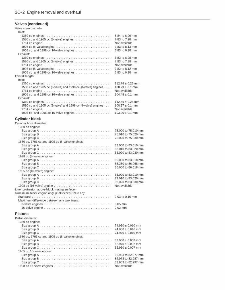
Valves (continued)Valve stem diameter:
Inlet:1360 cc engines . . . . . . . . . . . . . . . . . . . . . . . . . . . . . . . . . . . . . . . 6.84 to 6.99 mm1580 cc and 1905 cc (8-valve) engines . . . . . . . . . . . . . . . . . . . . . 7.83 to 7.98 mm1761 cc engine . . . . . . . . . . . . . . . . . . . . . . . . . . . . . . . . . . . . . . . . Not available1998 cc (8-valve) engine . . . . . . . . . . . . . . . . . . . . . . . . . . . . . . . . . 7.83 to 8.13 mm1905 cc and 1998 cc 16-valve engines . . . . . . . . . . . . . . . . . . . . . 6.83 to 6.98 mm
Exhaust:1360 cc engines . . . . . . . . . . . . . . . . . . . . . . . . . . . . . . . . . . . . . . . 6.83 to 6.98 mm1580 cc and 1905 cc (8-valve) engines . . . . . . . . . . . . . . . . . . . . . 7.83 to 7.98 mm1761 cc engine . . . . . . . . . . . . . . . . . . . . . . . . . . . . . . . . . . . . . . . . Not available1998 cc (8-valve) engine . . . . . . . . . . . . . . . . . . . . . . . . . . . . . . . . . 7.82 to 8.12 mm1905 cc and 1998 cc 16-valve engines . . . . . . . . . . . . . . . . . . . . . 6.83 to 6.98 mm
Overall length:Inlet:
1360 cc engines . . . . . . . . . . . . . . . . . . . . . . . . . . . . . . . . . . . . . . . 112.76 ± 0.25 mm1580 cc and 1905 cc (8-valve) and 1998 cc (8-valve) engines . . . . 108.79 ± 0.1 mm1761 cc engine . . . . . . . . . . . . . . . . . . . . . . . . . . . . . . . . . . . . . . . . Not available1905 cc and 1998 cc 16-valve engines . . . . . . . . . . . . . . . . . . . . . 104.48 ± 0.1 mm
Exhaust:1360 cc engines . . . . . . . . . . . . . . . . . . . . . . . . . . . . . . . . . . . . . . . 112.56 ± 0.25 mm1580 cc and 1905 cc (8-valve) and 1998 cc (8-valve) engines . . . . 108.37 ± 0.1 mm1761 cc engine . . . . . . . . . . . . . . . . . . . . . . . . . . . . . . . . . . . . . . . . Not available1905 cc and 1998 cc 16-valve engines . . . . . . . . . . . . . . . . . . . . . 103.00 ± 0.1 mm
Cylinder blockCylinder bore diameter:
1360 cc engine:Size group A . . . . . . . . . . . . . . . . . . . . . . . . . . . . . . . . . . . . . . . . . . 75.000 to 75.010 mmSize group B . . . . . . . . . . . . . . . . . . . . . . . . . . . . . . . . . . . . . . . . . . 75.010 to 75.020 mmSize group C . . . . . . . . . . . . . . . . . . . . . . . . . . . . . . . . . . . . . . . . . . 75.020 to 75.030 mm
1580 cc, 1761 cc and 1905 cc (8-valve) engines:Size group A . . . . . . . . . . . . . . . . . . . . . . . . . . . . . . . . . . . . . . . . . . 83.000 to 83.010 mmSize group B . . . . . . . . . . . . . . . . . . . . . . . . . . . . . . . . . . . . . . . . . . 83.010 to 83.020 mmSize group C . . . . . . . . . . . . . . . . . . . . . . . . . . . . . . . . . . . . . . . . . . 83.020 to 83.030 mm
1998 cc (8-valve) engines:Size group A . . . . . . . . . . . . . . . . . . . . . . . . . . . . . . . . . . . . . . . . . . 86.000 to 83.018 mmSize group B . . . . . . . . . . . . . . . . . . . . . . . . . . . . . . . . . . . . . . . . . . 86.250 to 86.268 mmSize group C . . . . . . . . . . . . . . . . . . . . . . . . . . . . . . . . . . . . . . . . . . 86.600 to 86.618 mm
1905 cc (16-valve) engine:Size group A . . . . . . . . . . . . . . . . . . . . . . . . . . . . . . . . . . . . . . . . . . 83.000 to 83.010 mmSize group B . . . . . . . . . . . . . . . . . . . . . . . . . . . . . . . . . . . . . . . . . . 83.010 to 83.020 mmSize group C . . . . . . . . . . . . . . . . . . . . . . . . . . . . . . . . . . . . . . . . . . 83.020 to 83.030 mm
1998 cc (16-valve) engine . . . . . . . . . . . . . . . . . . . . . . . . . . . . . . . . . . Not availableLiner protrusion above block mating surface - aluminium-block engine only (ie all except 1998 cc):
Standard . . . . . . . . . . . . . . . . . . . . . . . . . . . . . . . . . . . . . . . . . . . . . . . 0.03 to 0.10 mmMaximum difference between any two liners:
8-valve engines . . . . . . . . . . . . . . . . . . . . . . . . . . . . . . . . . . . . . . . . 0.05 mm16-valve engine . . . . . . . . . . . . . . . . . . . . . . . . . . . . . . . . . . . . . . . . 0.02 mm
PistonsPiston diameter:
1360 cc engine:Size group A . . . . . . . . . . . . . . . . . . . . . . . . . . . . . . . . . . . . . . . . . . 74.950 ± 0.010 mmSize group B . . . . . . . . . . . . . . . . . . . . . . . . . . . . . . . . . . . . . . . . . . 74.960 ± 0.010 mmSize group C . . . . . . . . . . . . . . . . . . . . . . . . . . . . . . . . . . . . . . . . . . 74.970 ± 0.010 mm
1580 cc, 1761 cc and 1905 cc (8-valve) engines:Size group A . . . . . . . . . . . . . . . . . . . . . . . . . . . . . . . . . . . . . . . . . . 82.960 ± 0.007 mmSize group B . . . . . . . . . . . . . . . . . . . . . . . . . . . . . . . . . . . . . . . . . . 82.970 ± 0.007 mmSize group C . . . . . . . . . . . . . . . . . . . . . . . . . . . . . . . . . . . . . . . . . . 82.980 ± 0.007 mm
1905 cc 16-valve engine:Size group A . . . . . . . . . . . . . . . . . . . . . . . . . . . . . . . . . . . . . . . . . . 82.963 to 82.977 mmSize group B . . . . . . . . . . . . . . . . . . . . . . . . . . . . . . . . . . . . . . . . . . 82.973 to 82.987 mmSize group C . . . . . . . . . . . . . . . . . . . . . . . . . . . . . . . . . . . . . . . . . . 82.983 to 82.997 mm
1998 cc 16-valve engines . . . . . . . . . . . . . . . . . . . . . . . . . . . . . . . . . . Not available
2C•2 Engine removal and overhaul

Connecting rodsMaximum weight difference between any two piston/connecting rod assemblies:
1360 cc engines . . . . . . . . . . . . . . . . . . . . . . . . . . . . . . . . . . . . . . . . . 5.0 g1580 cc, 1761 cc and 1905 cc engines . . . . . . . . . . . . . . . . . . . . . . . 13.0 g1998 cc engines . . . . . . . . . . . . . . . . . . . . . . . . . . . . . . . . . . . . . . . . . 7.0 g
CrankshaftEndfloat:
8-valve engines . . . . . . . . . . . . . . . . . . . . . . . . . . . . . . . . . . . . . . . . . . 0.07 to 0.32 mm16-valve engines . . . . . . . . . . . . . . . . . . . . . . . . . . . . . . . . . . . . . . . . . 0.07 to 0.27 mm
Main bearing journal diameter:1360 cc engines:
Standard . . . . . . . . . . . . . . . . . . . . . . . . . . . . . . . . . . . . . . . . . . . . . 49.965 to 49.981 mmUndersize . . . . . . . . . . . . . . . . . . . . . . . . . . . . . . . . . . . . . . . . . . . . 49.665 to 49.681 mm
1580 cc, 1905 cc and 1998 cc engines:Standard . . . . . . . . . . . . . . . . . . . . . . . . . . . . . . . . . . . . . . . . . . . . . 59.981 to 60.000 mmUndersize . . . . . . . . . . . . . . . . . . . . . . . . . . . . . . . . . . . . . . . . . . . . 59.681 to 59.700 mm
1761 cc engine . . . . . . . . . . . . . . . . . . . . . . . . . . . . . . . . . . . . . . . . . . Not availableBig-end bearing journal diameter:
1360 cc engines:Standard . . . . . . . . . . . . . . . . . . . . . . . . . . . . . . . . . . . . . . . . . . . . . 44.975 to 45.000 mmUndersize . . . . . . . . . . . . . . . . . . . . . . . . . . . . . . . . . . . . . . . . . . . . 44.675 to 44.700 mm
1580 cc, 1905 cc and 1998 cc engines:Standard . . . . . . . . . . . . . . . . . . . . . . . . . . . . . . . . . . . . . . . . . . . . . 49.984 to 50.000 mmUndersize . . . . . . . . . . . . . . . . . . . . . . . . . . . . . . . . . . . . . . . . . . . . 49.684 to 49.700 mm
1761 cc engine . . . . . . . . . . . . . . . . . . . . . . . . . . . . . . . . . . . . . . . . . . Not availableMaximum bearing journal out-of-round (all models) . . . . . . . . . . . . . . . 0.007 mmMain bearing running clearance:
1360 cc models*:Pre-February 1992 models . . . . . . . . . . . . . . . . . . . . . . . . . . . . . . . 0.023 to 0.083 mmFebruary 1992-on models . . . . . . . . . . . . . . . . . . . . . . . . . . . . . . . . 0.023 to 0.048 mm
1580 cc, 1761 cc and 1905 cc engines** . . . . . . . . . . . . . . . . . . . . . . . . . . . . . . . . . . . . . . . . 0.025 to 0.050 mm1998 cc engines . . . . . . . . . . . . . . . . . . . . . . . . . . . . . . . . . . . . . . . . . 0.038 to 0.069 mm
Big-end bearing running clearance - all models** . . . . . . . . . . . . . . . . . 0.025 to 0.050 mm
*On 1360 cc models, the main bearing shells were modified in February 1992, resulting in a reduction in the specified running clearance - see text for further information.
**These are suggested figures, typical for this type of engine - no exact values are stated by Peugeot.
Piston ringsNote: The following are suggested figures - no exact values are stated by Peugeot.End gaps:
Top compression ring:1360 cc engine . . . . . . . . . . . . . . . . . . . . . . . . . . . . . . . . . . . . . . . . 0.3 to 0.5 mm1580 cc engine . . . . . . . . . . . . . . . . . . . . . . . . . . . . . . . . . . . . . . . . 0.4 to 0.6 mm1905 cc engine . . . . . . . . . . . . . . . . . . . . . . . . . . . . . . . . . . . . . . . . 0.2 to 0.4 mm1761 cc and 1998 cc engines . . . . . . . . . . . . . . . . . . . . . . . . . . . . . 0.3 to 0.5 mm
Second compression ring:1360 cc engine . . . . . . . . . . . . . . . . . . . . . . . . . . . . . . . . . . . . . . . . 0.3 to 0.5 mm1580 cc and 1905 cc engines . . . . . . . . . . . . . . . . . . . . . . . . . . . . . 0.15 to 0.35 mm1761 cc and 1998 cc engines . . . . . . . . . . . . . . . . . . . . . . . . . . . . . 0.3 to 0.5 mm
Oil control ring:All models . . . . . . . . . . . . . . . . . . . . . . . . . . . . . . . . . . . . . . . . . . . . 0.3 to 0.5 mm
Torque wrench settings
TU series engineRefer to Chapter 2A Specifications
XU series engineRefer to Chapter 2B Specifications
Engine removal and overhaul 2C•3
2C
1 General information
Included in this Part of Chapter 2 are detailsof removing the engine/transmission from thecar and general overhaul procedures for thecylinder head, cylinder block/crankcase andall other engine internal components.
The information given ranges from adviceconcerning preparation for an overhaul andthe purchase of replacement parts, to detailedstep-by-step procedures covering removal,inspection, renovation and refitting of engineinternal components.
After Section 6, all instructions are basedon the assumption that the engine has beenremoved from the car. For informationconcerning in-car engine repair, as well as theremoval and refitting of those externalcomponents necessary for full overhaul, referto Part A or B of this Chapter (as applicable)and to Section 6. Ignore any preliminarydismantling operations described in Part A orB that are no longer relevant once the enginehas been removed from the car.
Apart from torque wrench settings, whichare given at the beginning of Part A or B (asapplicable), all specifications relating toengine overhaul are at the beginning of thisPart of Chapter 2.
2 Engine overhaul - general information
1 It is not always easy to determine when, orif, an engine should be completelyoverhauled, as a number of factors must beconsidered.2 High mileage is not necessarily anindication that an overhaul is needed, whilelow mileage does not preclude the need for anoverhaul. Frequency of servicing is probablythe most important consideration. An enginewhich has had regular and frequent oil andfilter changes, as well as other requiredmaintenance, should give many thousands ofmiles of reliable service. Conversely, aneglected engine may require an overhaulvery early in its life.3 Excessive oil consumption is an indicationthat piston rings, valve seals and/or valveguides are in need of attention. Make surethat oil leaks are not responsible beforedeciding that the rings and/or guides areworn. Perform a compression test, asdescribed in Part A of this Chapter, todetermine the likely cause of the problem.4 Check the oil pressure with a gauge fitted inplace of the oil pressure switch, and compareit with that specified. If it is extremely low, themain and big-end bearings, and/or the oilpump, are probably worn out.5 Loss of power, rough running, knocking ormetallic engine noises, excessive valve gear
noise, and high fuel consumption may alsopoint to the need for an overhaul, especially ifthey are all present at the same time. If acomplete service does not remedy thesituation, major mechanical work is the onlysolution.6 An engine overhaul involves restoring allinternal parts to the specification of a newengine. During an overhaul, the cylinder liners(where applicable), the pistons and the pistonrings are renewed. New main and big-endbearings are generally fitted; if necessary, thecrankshaft may be renewed, to restore thejournals. The valves are also serviced as well,since they are usually in less-than-perfectcondition at this point. While the engine isbeing overhauled, other components, such asthe distributor, starter and alternator, can beoverhauled as well. The end result should bean as-new engine that will give many trouble-free miles.
Note: Critical cooling system componentssuch as the hoses, thermostat and waterpump should be renewed when an engine isoverhauled. The radiator should be checkedcarefully, to ensure that it is not clogged orleaking. Also, it is a good idea to renew the oilpump whenever the engine is overhauled.
7 Before beginning the engine overhaul, readthrough the entire procedure, to familiariseyourself with the scope and requirements ofthe job. Overhauling an engine is not difficult ifyou follow all of the instructions carefully,have the necessary tools and equipment, andpay close attention to all specifications. It can,however, be time-consuming. Plan on the carbeing off the road for a minimum of twoweeks, especially if parts must be taken to anengineering works for repair or reconditioning.Check on the availability of parts and makesure that any necessary special tools andequipment are obtained in advance. Mostwork can be done with typical hand tools,although a number of precision measuringtools are required for inspecting parts todetermine if they must be renewed. Often theengineering works will handle the inspectionof parts and offer advice concerning recondi-tioning and renewal.
Note: Always wait until the engine has beencompletely dismantled, and until allcomponents (especially the cylinderblock/crankcase and the crankshaft) havebeen inspected, before deciding what serviceand repair operations must be performed byan engineering works. The condition of thesecomponents will be the major factor toconsider when determining whether tooverhaul the original engine, or to buy areconditioned unit. Do not, therefore,purchase parts or have overhaul work done onother components until they have beenthoroughly inspected. As a general rule, timeis the primary cost of an overhaul, so it doesnot pay to fit worn or sub-standard parts.
8 As a final note, to ensure maximum life andminimum trouble from a reconditioned engine,everything must be assembled with care, in aspotlessly-clean environment.
3 Engine/transmissionremoval - methods andprecautions
1 If you have decided that the engine must beremoved for overhaul or major repair work,several preliminary steps should be taken.2 Locating a suitable place to work isextremely important. Adequate work space,along with storage space for the car, will beneeded. If a workshop or garage is notavailable, at the very least, a flat, level, cleanwork surface is required.3 Cleaning the engine compartment andengine/transmission before beginning theremoval procedure will help keep tools cleanand organised.4 An engine hoist or A-frame will also benecessary. Ensure the equipment is rated inexcess of the combined weight of the engineand transmission. Safety is of primaryimportance, considering the potential hazardsin lifting the engine/transmission out of the car.5 If this is the first time you have removed anengine, an assistant should ideally beavailable. Advice and aid from someone moreexperienced would also be helpful. There aremany instances when one person cannotsimultaneously perform all of the operationsrequired when lifting the engine out of the car.6 Plan the operation ahead of time. Beforestarting work, arrange for the hire of or obtainall of the tools and equipment you will need.Some of the equipment necessary to performengine/transmission removal and installationsafely and with relative ease (in addition to anengine hoist) is as follows: a heavy duty trolleyjack, complete sets of spanners and socketsas described in the front of this manual,wooden blocks, and plenty of rags andcleaning solvent for mopping up spilled oil,coolant and fuel. If the hoist must be hired,make sure that you arrange for it in advance,and perform all of the operations possiblewithout it beforehand. This will save youmoney and time.7 Plan for the car to be out of use for quite awhile. An engineering works will be requiredto perform some of the work which the do-it-yourselfer cannot accomplish without specialequipment. These places often have a busyschedule, so it would be a good idea toconsult them before removing the engine, inorder to accurately estimate the amount oftime required to rebuild or repair componentsthat may need work.8 Always be extremely careful when removingand refitting the engine/transmission. Seriousinjury can result from careless actions. Planahead and take your time, and a job of thisnature, although major, can be accomplishedsuccessfully.
2C•4 Engine removal and overhaul

4 Engine and manualtransmission - removal,separation and refitting
4Note: Peugeot recommend that 8-valve XUengines are removed by lowering from theengine compartment, however in practise wefound that on models not fitted with airconditioning, there is ample room to lift theengine upwards. Lowering the engine wouldinvolve raising the front of the vehicle ontoaxle stands approximately 21 inches high andalso removing the engine subframe. Onmodels fitted with air conditioning the enginemay be lowered, or alternatively it can be liftedafter removing the condenser and front panel(the refrigerant must first be evacuated by aqualified engineer if this method is used).
RemovalNote: The engine can be removed from thecar only as a complete unit with thetransmission; the two are then separated foroverhaul.1 Park the vehicle on firm, level ground.Chock the rear wheels, then firmly apply thehandbrake. Jack up the front of the vehicle,and securely support it on axle stands (see“Jacking and Vehicle Support”). Remove bothfront roadwheels.2 Set the bonnet in the upright position, andremove the battery and tray as described inChapter 5A.3 On 8-valve XU engines remove the frontcross panel with reference to Chapter 11 (seenote at the beginning of this Section).4 Remove the complete air cleaner housingand duct assembly, as described in therelevant Part of Chapter 4 (see illustration).5 If the engine is to be dismantled, working asdescribed in Chapter 1, first drain the oil andremove the oil filter. Clean and refit the drainplug, tightening it securely.6 Drain the transmission oil as described inChapter 7A. Refit the drain and filler plugs,and tighten them to their specified torquesettings.7 Remove the alternator as described inChapter 5A.8 Where applicable, remove the powersteering pump as described in Chapter 10.
9 On models with air conditioning, unbolt thecompressor, and position it clear of theengine. Support the weight of the compressorby tying it to the vehicle body, to prevent anyexcess strain being placed on the compressorlines whilst the engine is removed. Do notdisconnect the refrigerant lines from thecompressor (refer to the warnings given inChapter 3).10 Drain the cooling system as described inChapter 1. Where necessary on 8-valve XUengines, remove the radiator (see Chapter 3).11 On carburettor models, carry out thefollowing operations, using the informationgiven in Chapter 4A:a) Disconnect the fuel feed hose from the
anti-percolation chamber.b) Disconnect the accelerator and choke
cables from the carburettor.c) Disconnect the braking system servo
vacuum hose from the inlet manifold.d) Remove the exhaust system front pipe.
12 On fuel injection models, carry out thefollowing operations, using the informationgiven in Chapter 4B or 4C (as applicable):a) Depressurise the fuel system, and
disconnect the fuel feed and return hoses.b) Disconnect the accelerator cable.c) Disconnect the fuel system wiring
connectors.d) Disconnect the purge valve and/or
braking system servo vacuum hoses fromthe inlet manifold (as applicable).
e) Remove the exhaust system front pipe.13 Referring to Chapter 3, release theretaining clip and disconnect the heater matrixhoses from their connection on the enginecompartment bulkhead.14 Working as described in Chapter 6,disconnect the clutch cable from thetransmission, and position it clear of theworking area (see illustration).15 Trace the wiring harness back from theengine to the wiring connector(s) in the enginecompartment. Release the locking ring(s) bytwisting them anti-clockwise and disconnectthe connectors. Also trace the harness lead(s)back to the relay box, situated beside thebattery. Unclip the wiring connector platefrom the front of the relay box cover thenundo the retaining nut and remove the cover.Lift up the engine harness lead cover then
undo the nut(s) and release the lead(s) fromthe relay box. Check that all the relevantconnectors have been disconnected, and thatthe wiring is released from any relevant clipsor ties, so that it is free to be removed with theengine/transmission.16 From underneath the vehicle, slacken andremove the nuts and bolts securing the rearmounting link to the mounting assembly andsubframe, and remove the link.17 Remove both driveshafts as described inChapter 8.18 Carry out the following operations, usingthe information given in Chapter 7A:a) Disconnect the gearchange selector
rod/link rods (as applicable) from thetransmission.
b) Disconnect the speedometer cable fromthe speedometer drive.
c) Disconnect the wiring connector(s) fromthe reversing light switch andspeedometer drive (as applicable).
19 Manoeuvre the engine hoist into position,and attach it to the lifting brackets bolted ontothe cylinder head. Raise the hoist until it issupporting the weight of the engine.20 Remove the right-hand engine mountingwith reference to Chapter 2A.
Note: On certain models, if the right-handengine mounting hydro-elastic unit is to berenewed because of wear/perishing, a specialtool is needed to unscrew it from the wingpanel, and for refitting and tightening to thespecified torque (see illustration).
21 Slacken and remove the centre nut andwasher from the engine/transmission left-hand mounting. Undo the two nuts andwashers securing the mounting to its bracketand remove the mounting from the enginecompartment and recover the spacer (wherefitted). To improve clearance, (where possible)undo the two retaining bolts and remove thebracket from the body.22 Make a final check that any componentswhich would prevent the removal of theengine/transmission from the car have beenremoved or disconnected. Ensure thatcomponents such as the gearchange selectorrod are secured so that they cannot bedamaged on removal.
Engine removal and overhaul 2C•5
4.20 Special tool for removing and refittingright-hand engine mounting
hydro-elastic unit4.14 Disconnecting the clutch cable4.4 Inlet air duct connection to the front
crossmember
2C
23 Lift the engine/transmission out of the car,ensuring that nothing is trapped or damaged.Enlist the help of an assistant during thisprocedure, as it will be necessary to tilt theassembly slightly to clear the body panels. Onmodels equipped with anti-lock brakes, greatcare must be taken to ensure that the anti-lock braking system unit is not damagedduring the removal procedure.24 Once the engine is high enough, lift it outover the front of the body, and lower the unitto the ground.
Separation25 With the engine/transmission assemblyremoved, support the assembly on suitableblocks of wood, on a workbench (or alter-natively, on a clean area of the workshopfloor).26 Undo the retaining bolts, and remove theflywheel lower cover plate (where fitted) fromthe transmission.27 On models with a “pull-type” clutchrelease mechanism (see Chapter 6 for furtherinformation), tap out the retaining pin orunscrew the retaining bolt (as applicable), andremove the clutch release lever from the topof the release fork shaft. This is necessary toallow the fork shaft to rotate freely, so that itdisengages from the release bearing as thetransmission is pulled away from the engine.Make an alignment mark across the centre ofthe clutch release fork shaft, using a scriber,paint or similar, and mark its relative positionon the transmission housing (see Chapter 7Afor further information).28 Slacken and remove the retaining bolts,and remove the starter motor from thetransmission.29 Ensure that both engine and transmissionare adequately supported, then slacken andremove the remaining bolts securing thetransmission housing to the engine. Note thecorrect fitted positions of each bolt (and therelevant brackets) as they are removed, to useas a reference on refitting.30 Carefully withdraw the transmission fromthe engine, ensuring that the weight of thetransmission is not allowed to hang on theinput shaft while it is engaged with the clutchfriction disc.31 If they are loose, remove the locatingdowels from the engine or transmission, andkeep them in a safe place.32 On models with a “pull-type” clutch, makea second alignment mark on the transmissionhousing, marking the relative position of therelease fork mark after removal. This shouldindicate the angle at which the release fork ispositioned. The mark can then be used toposition the release fork prior to installation, toensure that the fork correctly engages withthe clutch release bearing as the transmissionis installed.
Refitting33 If the engine and transmission have beenseparated, perform the operations described
below in paragraphs 34 to 42. If not, proceedas described from paragraph 43 onwards.34 Apply a smear of high-melting-pointgrease (Peugeot recommend the use ofMolykote BR2 plus - available from yourPeugeot dealer) to the splines of thetransmission input shaft. Do not apply toomuch, otherwise there is a possibility of thegrease contaminating the clutch friction plate.35 Ensure that the locating dowels arecorrectly positioned in the engine ortransmission.36 On models with a “pull-type” clutch,before refitting, position the clutch releasebearing so that its arrow mark is pointingupwards (bearing fork slots facing towards thefront of the engine), and align the release forkshaft mark with the second mark made on thetransmission housing (release fork positionedat approximately 60° to clutch housing face).This will ensure that the release fork andbearing will engage correctly as thetransmission is refitted to the engine.37 Carefully offer the transmission to theengine, until the locating dowels are engaged.Ensure that the weight of the transmission isnot allowed to hang on the input shaft as it isengaged with the clutch friction disc.38 On models with a “pull-type” clutch, withthe transmission fully engaged with theengine, check that the release fork andbearing are correctly engaged. If the releasefork and bearing are correctly engaged, themark on the release fork should be alignedwith the original mark made on thetransmission housing (see Chapter 7A forfurther information).39 Refit the transmission housing-to-enginebolts, ensuring that all the necessary bracketsare correctly positioned, and tighten them tothe specified torque setting.40 Refit the starter motor, and securelytighten its retaining bolts.41 On models with a “pull-type” clutchrelease mechanism, refit the clutch releaselever to the top of the release fork shaft,securing it in position with its retaining pin orbolt (as applicable).42 Where necessary, refit the lower flywheelcover plate to the transmission, and securelytighten its retaining bolts.43 Reconnect the hoist and lifting tackle tothe engine lifting brackets. With the aid of anassistant, lift the assembly over the enginecompartment.44 The assembly should be tilted asnecessary to clear the surroundingcomponents, as during removal; lower theassembly into position in the enginecompartment, manipulating the hoist andlifting tackle as necessary.45 With the engine/transmission in position,refit the right-hand engine/transmissionmounting bracket, tightening its retaining nutsand bolts (as applicable) by hand only at thisstage.46 Working on the left-hand mounting, refitthe mounting bracket (where removed) to the
body and tighten its retaining bolts to thespecified torque. Refit the mounting rubberand refit the mounting retaining nuts andwashers and the centre nut and washer,tightening them lightly only.47 From underneath the vehicle, refit the rearmounting link and install both its bolts.48 Rock the engine to settle it on itsmountings then go around and tighten all themounting nuts and bolts to their specifiedtorque settings. Where necessary, once theright-hand mounting bracket nuts have beentightened, refit the rubber damper and curvedretaining plate, tightening its retaining bolts tothe specified torque. The hoist can then bedetached from the engine and removed.49 The remainder of the refitting procedure isa direct reversal of the removal sequence,noting the following points:a) Ensure that the wiring loom is correctly
routed and retained by all the relevantretaining clips; all connectors should becorrectly and securely reconnected.
b) Prior to refitting the driveshafts to thetransmission, renew the driveshaft oilseals as described in Chapter 7A.
c) Ensure that all coolant hoses are correctlyreconnected, and securely retained bytheir retaining clips.
d) Adjust the clutch cable as described inChapter 6.
e) Adjust the choke cable and/or acceleratorcable (as applicable) as described in therelevant Part of Chapter 4.
f) Refill the engine and transmission withcorrect quantity and type of lubricant, asdescribed in Chapter 7A.
g) Refill the cooling system as described inChapter 1.
5 Engine and automatictransmission - removal,separation and refitting
4RemovalNote: The engine can be removed from thecar only as a complete unit with thetransmission; the two are then separated foroverhaul.1 Carry out the relevant operations describedin paragraphs 1 to 24 of Section 4, noting thatthe transmission oil draining procedure isgiven in Chapter 1. Before lifting the enginefrom the engine compartment, carry out thefollowing operations, using the informationgiven in Chapter 7B:a) Remove the transmission dipstick tube.b) Disconnect the wiring from the starter
inhibitor/reversing light switch and thespeedometer drive housing. Release theearth strap(s) from the top of thetransmission housing.
c) Disconnect the selector cable.d) Release the power steering pipe from the
transmission.e) Disconnect the speedometer cable.
2C•6 Engine removal and overhaul

Separation2 With the engine/transmission assemblyremoved, support the assembly on suitableblocks of wood, on a workbench (or failingthat, on a clean area of the workshop floor).3 Detach the kickdown cable from the throttlecam. Work back along the cable, freeing itfrom any retaining clips, and noting its correctrouting.4 Undo the retaining bolts and remove thedriveplate lower cover plate from thetransmission, to gain access to the torqueconverter retaining bolts. Slacken and removethe visible bolt. Rotate the crankshaft using asocket and extension bar on the pulley bolt,and undo the remaining bolts securing thetorque converter to the driveplate as theybecome accessible. There are three bolts intotal.5 Slacken and remove the retaining bolts,and remove the starter motor from thetransmission.6 To ensure that the torque converter doesnot fall out as the transmission is removed,secure it in position using a length of metalstrip bolted to one of the starter motor boltholes.7 Ensure that both the engine andtransmission are adequately supported, thenslacken and remove the remaining boltssecuring the transmission housing to theengine. Note the correct fitted positions ofeach bolt (and any relevant brackets) as theyare removed, to use as a reference onrefitting.8 Carefully withdraw the transmission fromthe engine. If the locating dowels are a loosefit in the engine/transmission, remove themand keep them in a safe place.
Refitting9 If the engine and transmission have beenseparated, perform the operations describedbelow in paragraphs 10 to 16. If not, proceedas described from paragraph 17 onwards.10 Ensure that the bush fitted to the centre ofthe crankshaft is in good condition. Apply alittle Molykote G1 grease (available from yourPeugeot dealer) to the torque convertercentring pin. Do not apply too much,otherwise there is a possibility of the greasecontaminating the torque converter.11 Ensure that the locating dowels arecorrectly positioned in the engine ortransmission.12 Carefully offer the transmission to theengine, until the locating dowels are engaged.13 Refit the transmission housing-to-enginebolts, ensuring that all the necessary bracketsare correctly positioned, and tighten them tothe specified torque setting.14 Remove the torque converter retainingstrap installed prior to removal. Align thetorque converter threaded holes with theretaining plate, and refit the three retainingbolts.15 Tighten the torque converter retaining
bolts to the specified torque setting, then refitthe driveplate lower cover.16 Refit the starter motor, and securelytighten its retaining bolts.17 Refit the engine to the vehicle withreference to Section 4.18 The remainder of the refitting procedure isa reversal of the removal sequence, noting thefollowing points:a) Ensure that the wiring loom is correctly
routed, and retained by all the relevantretaining clips; all connectors should becorrectly and securely reconnected.
b) Prior to refitting the driveshafts to thetransmission, renew the driveshaft oilseals as described in Chapter 7B.
c) Ensure that all coolant hoses are correctlyreconnected, and securely retained bytheir retaining clips.
d) Adjust the selector cable and kickdowncable as described in Chapter 7B.
e) Adjust the accelerator cable as describedin Chapter 4.
f) Refill the engine and transmission withcorrect quantity and type of lubricant, asdescribed in Chapter 1.
g) Refill the cooling system as described inChapter 1.
6 Engine overhaul - dismantling sequence
1 It is much easier to dismantle and work onthe engine if it is mounted on a portableengine stand. These stands can often be hiredfrom a tool hire shop. Before the engine ismounted on a stand, the flywheel/driveplateshould be removed, so that the stand boltscan be tightened into the end of the cylinderblock/crankcase.2 If a stand is not available, it is possible todismantle the engine with it blocked up on asturdy workbench, or on the floor. Be extra-careful not to tip or drop the engine whenworking without a stand.3 If you are going to obtain a reconditionedengine, all the external components must beremoved first, to be transferred to thereplacement engine (just as they will if you aredoing a complete engine overhaul yourself).These components include the following:a) Alternator mounting brackets.b) Power steering pump and air conditioning
compressor brackets (where fitted).c) Thermostat and housing, and coolant
outlet chamber/elbow (Chapter 3).d) Dipstick tube.e) Carburettor/fuel system components
(Chapter 4).f) All electrical switches and sensors.g) Inlet and exhaust manifolds (Chapter 4).h) Oil filter (Chapter 1).i) Fuel pump - carburettor engines only
(Chapter 4).j) Flywheel/driveplate (Part A or B of this
Chapter).
Note: When removing the externalcomponents from the engine, pay closeattention to details that may be helpful orimportant during refitting. Note the fittedposition of gaskets, seals, spacers, pins,washers, bolts, and other small items.4 If you are obtaining a “short” engine (whichconsists of the engine cylinder block/crankcase, crankshaft, pistons andconnecting rods all assembled), then thecylinder head, sump, oil pump, and timing beltwill have to be removed also.5 If you are planning a complete overhaul, theengine can be dismantled, and the internalcomponents removed, in the order givenbelow, referring to Part A or B of this Chapterunless otherwise stated.a) Inlet and exhaust manifolds (Chapter 4).b) Timing belt, sprockets and tensioner(s).c) Cylinder head.d) Flywheel/driveplate.e) Sump.f) Oil pump.g) Piston/connecting rod assemblies
(Section 10).h) Crankshaft (Section 11).
6 Before beginning the dismantling andoverhaul procedures, make sure that you haveall of the correct tools necessary. Refer to“Tools and working facilities” for furtherinformation.
7 Cylinder head - dismantling 3Note: New and reconditioned cylinder headsare available from the manufacturer, and fromengine overhaul specialists. Be aware thatsome specialist tools are required for thedismantling and inspection procedures, andnew components may not be readily available.It may therefore be more practical andeconomical for the home mechanic topurchase a reconditioned head, rather thandismantle, inspect and recondition the originalhead.1 Remove the cylinder head as described inPart A or B of this Chapter (as applicable).2 If not already done, remove the inlet andexhaust manifolds with reference to therelevant Part of Chapter 4.3 Remove the camshaft(s), followers andshims (as applicable) as described in Part A orB of this Chapter.4 Using a valve spring compressor, compresseach valve spring in turn until the split colletscan be removed. Release the compressor,and lift off the spring retainer, spring andspring seat. Using a pair of pliers, carefullyextract the valve stem seal from the top of theguide (see illustrations).5 If, when the valve spring compressor isscrewed down, the spring retainer refuses tofree and expose the split collets, gently tapthe top of the tool, directly over the retainer,with a light hammer. This will free the retainer.
Engine removal and overhaul 2C•7
2C
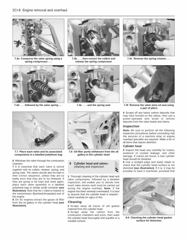
6 Withdraw the valve through the combustionchamber.7 It is essential that each valve is storedtogether with its collets, retainer, spring, andspring seat. The valves should also be kept intheir correct sequence, unless they are sobadly worn that they are to be renewed. Ifthey are going to be kept and used again,place each valve assembly in a labelledpolythene bag or similar small container (seeillustration). Note that No 1 valve is nearest tothe transmission (flywheel/driveplate) end ofthe engine.8 On XU engines extract the gauze oil filterfrom the oil gallery in the cylinder head (seeillustration).
8 Cylinder head and valves -cleaning and inspection 2
1 Thorough cleaning of the cylinder head andvalve components, followed by a detailedinspection, will enable you to decide howmuch valve service work must be carried outduring the engine overhaul. Note: If theengine has been severely overheated, it is bestto assume that the cylinder head is warped -check carefully for signs of this.
Cleaning2 Scrape away all traces of old gasketmaterial from the cylinder head.3 Scrape away the carbon from thecombustion chambers and ports, then washthe cylinder head thoroughly with paraffin or asuitable solvent.
4 Scrape off any heavy carbon deposits thatmay have formed on the valves, then use apower-operated wire brush to removedeposits from the valve heads and stems.
InspectionNote: Be sure to perform all the followinginspection procedures before concluding thatthe services of a machine shop or engineoverhaul specialist are required. Make a list ofall items that require attention.
Cylinder head5 Inspect the head very carefully for cracks,evidence of coolant leakage, and otherdamage. If cracks are found, a new cylinderhead should be obtained.6 Use a straight-edge and feeler blade tocheck that the cylinder head surface is notdistorted (see illustration). If it is, it may bepossible to have it machined, provided that
8.6 Checking the cylinder head gasketsurface for distortion
7.8 Oil filter partly withdrawn from the oilgallery in the cylinder head
7.7 Place each valve and its associatedcomponents in a labelled polythene bag
2C•8 Engine removal and overhaul
7.4a Compress the valve spring using aspring compressor . . .
7.4c Remove the spring retainer . . .
7.4f Remove the valve stem oil seal usinga pair of pliers
7.4e . . . and the spring seat7.4d . . . followed by the valve spring . . .
7.4b . . . then extract the collets andrelease the spring compressor

the cylinder head is not reduced to less thanthe specified height.7 Examine the valve seats in each of thecombustion chambers. If they are severelypitted, cracked, or burned, they will need tobe renewed or re-cut by an engine overhaulspecialist. If they are only slightly pitted, thiscan be removed by grinding-in the valveheads and seats with fine valve-grindingcompound, as described below.8 Check the valve guides for wear byinserting the relevant valve, and checking forside-to-side motion of the valve. A very smallamount of movement is acceptable. If themovement seems excessive, remove thevalve. Measure the valve stem diameter (seebelow), and renew the valve if it is worn. If thevalve stem is not worn, the wear must be inthe valve guide, and the guide must berenewed. The renewal of valve guides is bestcarried out by a Peugeot dealer or engineoverhaul specialist, who will have thenecessary tools available. Where no valvestem diameter is specified, seek the advice ofa Peugeot dealer on the best course of action.9 If renewing the valve guides, the valve seatsshould be re-cut or re-ground only after theguides have been fitted.
Valves10 Examine the head of each valve forpitting, burning, cracks, and general wear.Check the valve stem for scoring and wearridges. Rotate the valve, and check for anyobvious indication that it is bent. Look for pitsor excessive wear on the tip of each valvestem. Renew any valve that shows any suchsigns of wear or damage.11 If the valve appears satisfactory at thisstage, measure the valve stem diameter atseveral points using a micrometer (seeillustration). Any significant difference in thereadings obtained indicates wear of the valvestem. Should any of these conditions beapparent, the valve(s) must be renewed.12 If the valves are in satisfactory condition,they should be ground (lapped) into theirrespective seats, to ensure a smooth, gas-tight seal. If the seat is only lightly pitted, or ifit has been re-cut, fine grinding compoundonly should be used to produce the requiredfinish. Coarse valve-grinding compoundshould not be used, unless a seat is badlyburned or deeply pitted. If this is the case, the
cylinder head and valves should be inspectedby an expert, to decide whether seat re-cutting, or even the renewal of the valve orseat insert (where possible) is required.13 Valve grinding is done as follows. Placethe cylinder head upside-down on a bench.14 Smear a trace of (the appropriate gradeof) valve-grinding compound on the seat face,and press a suction grinding tool onto thevalve head (see illustration). With a semi-rotary action, grind the valve head to its seat,lifting the valve occasionally to redistribute thegrinding compound. A light spring placedunder the valve head will greatly ease thisoperation.15 If coarse grinding compound is beingused, work only until a dull, matt even surfaceis produced on both the valve seat and thevalve, then wipe off the used compound, andrepeat the process with fine compound. Whena smooth unbroken ring of light grey mattfinish is produced on both the valve and seat,the grinding operation is complete. Do notgrind-in the valves any further than absolutelynecessary, or the seat will be prematurelysunk into the cylinder head.16 When all the valves have been ground-in,carefully wash off all traces of grindingcompound using paraffin or a suitable solvent,before reassembling the cylinder head.
Valve components17 Examine the valve springs for signs ofdamage and discoloration. No minimum freelength is specified by Peugeot, so the onlyway of judging valve spring wear is bycomparison with a new component.18 Stand each spring on a flat surface, and
check it for squareness. If any of the springsare damaged, distorted or have lost theirtension, obtain a complete new set of springs.It is normal to renew the valve springs as amatter of course if a major overhaul is beingcarried out.19 Renew the valve stem oil seals regardlessof their apparent condition.
9 Cylinder head - reassembly 31 Lubricate the stems of the valves, andinsert the valves into their original locations(see illustration). If new valves are beingfitted, insert them into the locations to whichthey have been ground.2 Refit the spring seat then, working on thefirst valve, dip the new valve stem seal in freshengine oil. Carefully locate it over the valveand onto the guide. Take care not to damagethe seal as it is passed over the valve stem.Use a suitable socket or metal tube to pressthe seal firmly onto the guide (seeillustration).3 Locate the valve spring on top of its seat,then refit the spring retainer.4 Compress the valve spring, and locate thesplit collets in the recess in the valve stem.Release the compressor, then repeat theprocedure on the remaining valves.
5 With all the valves installed, place thecylinder head flat on the bench and, using ahammer and interposed block of wood, tapthe end of each valve stem to settle thecomponents.6 Refit the camshaft(s), followers and shims(as applicable) as described in Part A or B ofthis Chapter.7 On XU engines refit the gauze oil filter(clean) to the oil gallery in the cylinder head. Ifthe filter is damaged fit a new one.8 The cylinder head can then be refitted asdescribed in Part A or B of this Chapter.
Engine removal and overhaul 2C•9
9.1 Lubricate the valve stems prior to refitting
8.14 Grinding-in a valve8.11 Measuring a valve stem diameter
2C
9.2 Fitting a valve stem oil seal using a socket
Use a little dab of grease tohold the collets on the valvestem while the springcompressor is released.
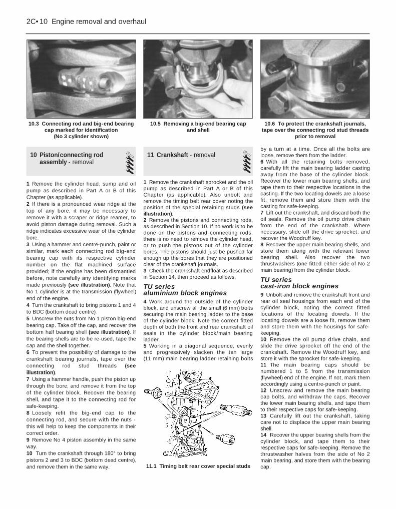
10 Piston/connecting rodassembly - removal 4
1 Remove the cylinder head, sump and oilpump as described in Part A or B of thisChapter (as applicable).2 If there is a pronounced wear ridge at thetop of any bore, it may be necessary toremove it with a scraper or ridge reamer, toavoid piston damage during removal. Such aridge indicates excessive wear of the cylinderbore.3 Using a hammer and centre-punch, paint orsimilar, mark each connecting rod big-endbearing cap with its respective cylindernumber on the flat machined surfaceprovided; if the engine has been dismantledbefore, note carefully any identifying marksmade previously (see illustration). Note thatNo 1 cylinder is at the transmission (flywheel)end of the engine.4 Turn the crankshaft to bring pistons 1 and 4to BDC (bottom dead centre).5 Unscrew the nuts from No 1 piston big-endbearing cap. Take off the cap, and recover thebottom half bearing shell (see illustration). Ifthe bearing shells are to be re-used, tape thecap and the shell together.6 To prevent the possibility of damage to thecrankshaft bearing journals, tape over theconnecting rod stud threads (seeillustration).7 Using a hammer handle, push the piston upthrough the bore, and remove it from the topof the cylinder block. Recover the bearingshell, and tape it to the connecting rod forsafe-keeping.8 Loosely refit the big-end cap to theconnecting rod, and secure with the nuts -this will help to keep the components in theircorrect order.9 Remove No 4 piston assembly in the sameway.10 Turn the crankshaft through 180° to bringpistons 2 and 3 to BDC (bottom dead centre),and remove them in the same way.
11 Crankshaft - removal 41 Remove the crankshaft sprocket and the oilpump as described in Part A or B of thisChapter (as applicable). Also unbolt andremove the timing belt rear cover noting theposition of the special retaining studs (seeillustration).2 Remove the pistons and connecting rods,as described in Section 10. If no work is to bedone on the pistons and connecting rods,there is no need to remove the cylinder head,or to push the pistons out of the cylinderbores. The pistons should just be pushed farenough up the bores that they are positionedclear of the crankshaft journals.3 Check the crankshaft endfloat as describedin Section 14, then proceed as follows.
TU series aluminium block engines 4 Work around the outside of the cylinderblock, and unscrew all the small (6 mm) boltssecuring the main bearing ladder to the baseof the cylinder block. Note the correct fitteddepth of both the front and rear crankshaft oilseals in the cylinder block/main bearingladder.5 Working in a diagonal sequence, evenlyand progressively slacken the ten large (11 mm) main bearing ladder retaining bolts
by a turn at a time. Once all the bolts areloose, remove them from the ladder.6 With all the retaining bolts removed,carefully lift the main bearing ladder castingaway from the base of the cylinder block.Recover the lower main bearing shells, andtape them to their respective locations in thecasting. If the two locating dowels are a loosefit, remove them and store them with thecasting for safe-keeping.7 Lift out the crankshaft, and discard both theoil seals. Remove the oil pump drive chainfrom the end of the crankshaft. Wherenecessary, slide off the drive sprocket, andrecover the Woodruff key.8 Recover the upper main bearing shells, andstore them along with the relevant lowerbearing shell. Also recover the twothrustwashers (one fitted either side of No 2main bearing) from the cylinder block.
TU series cast-iron block engines9 Unbolt and remove the crankshaft front andrear oil seal housings from each end of thecylinder block, noting the correct fittedlocations of the locating dowels. If thelocating dowels are a loose fit, remove themand store them with the housings for safe-keeping.10 Remove the oil pump drive chain, andslide the drive sprocket off the end of thecrankshaft. Remove the Woodruff key, andstore it with the sprocket for safe-keeping.11 The main bearing caps should benumbered 1 to 5 from the transmission(flywheel) end of the engine. If not, mark themaccordingly using a centre-punch or paint.12 Unscrew and remove the main bearingcap bolts, and withdraw the caps. Recoverthe lower main bearing shells, and tape themto their respective caps for safe-keeping.13 Carefully lift out the crankshaft, takingcare not to displace the upper main bearingshell.14 Recover the upper bearing shells from thecylinder block, and tape them to theirrespective caps for safe-keeping. Remove thethrustwasher halves from the side of No 2main bearing, and store them with the bearingcap.
2C•10 Engine removal and overhaul
10.3 Connecting rod and big-end bearingcap marked for identification
(No 3 cylinder shown)
10.6 To protect the crankshaft journals,tape over the connecting rod stud threads
prior to removal
11.1 Timing belt rear cover special studs
10.5 Removing a big-end bearing cap and shell

XU series engines15 Slacken and remove the retaining bolts,and remove the oil seal carrier from the front(timing belt) end of the cylinder block, alongwith its gasket (where fitted) (see illustration).16 Remove the oil pump drive chain, andslide the drive sprocket and spacer (wherefitted) off the end of the crankshaft. Removethe Woodruff key, and store it with thesprocket for safe-keeping (see illustrations).17 The main bearing caps should benumbered 1 to 5, starting from thetransmission (flywheel/driveplate) end of theengine (see illustration). If not, mark themaccordingly using a centre-punch. Also notethe correct fitted depth of the rear crankshaftoil seal in the bearing cap.18 On 1761 cc engines, undo the two bolts(one at the front of the block, and one at therear) securing the centre main bearing cap to
the block. Remove the bolts, along with theirsealing washers.19 On all engines, slacken and remove themain bearing cap retaining bolts/nuts, and liftoff each bearing cap. Recover the lowerbearing shells, and tape them to theirrespective caps for safe-keeping. Alsorecover the lower thrustwasher halves fromthe side of No 2 main bearing cap (seeillustration). Remove the rubber sealing stripsfrom the sides of No 1 main bearing cap, anddiscard them.20 Lift out the crankshaft, and discard therear oil seal (see illustration).21 Recover the upper bearing shells from thecylinder block, and tape them to theirrespective caps for safe-keeping (seeillustration). Remove the upper thrustwasherhalves from the side of No 2 main bearing,and store them with the lower halves.
Engine removal and overhaul 2C•11
11.16b . . . then slide off the drive sprocket . . .
11.19 Removing No 2 main bearing cap.Note the thrustwasher (arrowed)
11.17 Main bearing cap identificationmarkings (arrowed)
11.16c . . . and remove the Woodruff keyfrom the crankshaft
11.16a Remove the oil pump drive chain . . .
11.15 Removing the oil seal carrier fromthe front of the cylinder block - XU engine
2C
11.20 Lifting out the crankshaft - XU series engine
11.21 Remove the upper main bearingshells from the cylinder block/crankcase,
and store them with their lower shells
12.1 Cylinder block core plugs (arrowed)
12 Cylinder block/crankcase -cleaning and inspection 2
Cleaning1 Remove all external components andelectrical switches/sensors from the block.For complete cleaning, the core plugs shouldideally be removed (see illustration). Drill asmall hole in the plugs, then insert a self-tapping screw into the hole. Pull out the plugsby pulling on the screw with a pair of grips, orby using a slide hammer.2 On aluminium block engines with wet liners,remove the liners, referring to paragraph 18.3 Where applicable, undo the retaining boltand remove the piston oil jet spray tube frominside the cylinder block.4 Scrape all traces of gasket from the cylinderblock/crankcase, and from the main bearing

ladder (where fitted), taking care not todamage the gasket/sealing surfaces.5 Remove all oil gallery plugs (where fitted).The plugs are usually very tight - they mayhave to be drilled out, and the holes re-tapped. Use new plugs when the engine isreassembled.6 If any of the castings are extremely dirty, allshould be steam-cleaned.7 After the castings are returned, clean all oilholes and oil galleries one more time. Flush allinternal passages with warm water until thewater runs clear. Dry thoroughly, and apply alight film of oil to all mating surfaces, toprevent rusting. On cast-iron block engines,also oil the cylinder bores. If you have accessto compressed air, use it to speed up thedrying process, and to blow out all the oilholes and galleries.
8 If the castings are not very dirty, you can doan adequate cleaning job with hot (as hot asyou can stand!), soapy water and a stiff brush.Take plenty of time, and do a thorough job.Regardless of the cleaning method used, besure to clean all oil holes and galleries verythoroughly, and to dry all components well.On cast-iron block engines, protect thecylinder bores as described above, to preventrusting.9 All threaded holes must be clean, to ensureaccurate torque readings during reassembly.To clean the threads, run the correct-size tapinto each of the holes to remove rust,corrosion, thread sealant or sludge, and torestore damaged threads (see illustration). Ifpossible, use compressed air to clear theholes of debris produced by this operation.
10 Apply suitable sealant to the new oilgallery plugs, and insert them into the holes inthe block. Tighten them securely.11 Where applicable, clean the threads of thepiston oil jet retaining bolt, and apply a dropof thread-locking compound to the boltthreads. Refit the piston oil jet spray tube tothe cylinder block, and tighten its retainingbolt to the specified torque setting.12 If the engine is not going to bereassembled right away, cover it with a largeplastic bag to keep it clean; protect all matingsurfaces and the cylinder bores as describedabove, to prevent rusting.
Inspection
Cast-iron cylinder block13 Visually check the castings for cracks andcorrosion. Look for stripped threads in thethreaded holes. If there has been any historyof internal water leakage, it may be worthwhilehaving an engine overhaul specialist checkthe cylinder block/crankcase with specialequipment. If defects are found, have themrepaired if possible, or renew the assembly.14 Check each cylinder bore for scuffing andscoring. Check for a wear ridge at the top of thecylinder, indicating that the bore is badly worn.15 If the necessary measuring equipment isavailable, measure the bore diameter of eachcylinder liner at the top (just under the wearridge), centre, and bottom of the cylinderbore, parallel to the crankshaft axis.16 Next, measure the bore diameter at thesame three locations, at right-angles to thecrankshaft axis. Compare the results with thefigures given in the Specifications. Where nofigures are stated by Peugeot, if there is anydoubt about the condition of the cylinderbores seek the advice of a Peugeot dealer orsuitable engine reconditioning specialist.17 At the time of writing, it was not clearwhether oversize pistons were available for allmodels. Consult your Peugeot dealer for thelatest information on piston availability. Ifoversize pistons are available then it may bepossible to have the cylinder bores reboredand fit the oversize pistons. If it provesoversize pistons are not available, and thebores are worn, renewal of the block seems tobe the only option.
Aluminium cylinder block with wet liners18 Remove the liner clamps (where used),then use a hard wood drift to tap out eachliner from the inside of the cylinder block.When all the liners are released, tip thecylinder block/crankcase on its side andremove each liner from the top of the block.As each liner is removed, stick masking tapeon its left-hand (transmission side) face, andwrite the cylinder number on the tape. No 1cylinder is at the transmission (flywheel/driveplate) end of the engine. Remove the O-ring from the base of each liner, and discard(see illustrations).19 Check each cylinder liner for scuffing andscoring. Check for signs of a wear ridge at thetop of the liner, indicating that the bore isexcessively worn.20 If the necessary measuring equipment isavailable, measure the bore diameter of eachcylinder liner at the top (just under the wearridge), centre, and bottom of the cylinderbore, parallel to the crankshaft axis.21 Next, measure the bore diameter at thesame three locations, at right-angles to thecrankshaft axis. Compare the results with thefigures given in the Specifications.22 Repeat the procedure for the remainingcylinder liners.23 If the liner wear exceeds the permittedtolerances at any point, or if the cylinder linerwalls are badly scored or scuffed, thenrenewal of the relevant liner assembly will benecessary. If there is any doubt about thecondition of the cylinder bores, seek theadvice of a Peugeot dealer or engine recondi-tioning specialist.24 If renewal is necessary, new liners,complete with pistons and piston rings, canbe purchased from a Peugeot dealer. Notethat it is not possible to buy liners individually- they are supplied only as a matchedassembly complete with piston and rings.25 To allow for manufacturing tolerances,pistons and liners are separated into threesize groups. The size group of each piston isindicated by a letter (A, B or C) stamped ontoits crown, and the size group of each liner isindicated by a series of 1 to 3 notches on theupper lip of the liner; a single notch for group A, two notches for group B, and three
2C•12 Engine removal and overhaul
12.9 Cleaning a cylinder block threadedhole using a suitable tap
12.18b . . . and recover the bottom O-ring seal (arrowed)
12.18a On aluminium block engines,remove each liner . . .
Warning: Wear eye protectionwhen using compressed air!
Warning: Wear eye protectionwhen cleaning out these holesin this way!
A good alternative is toinject aerosol-applied water-dispersant lubricant intoeach hole, using the long
spout usually supplied.
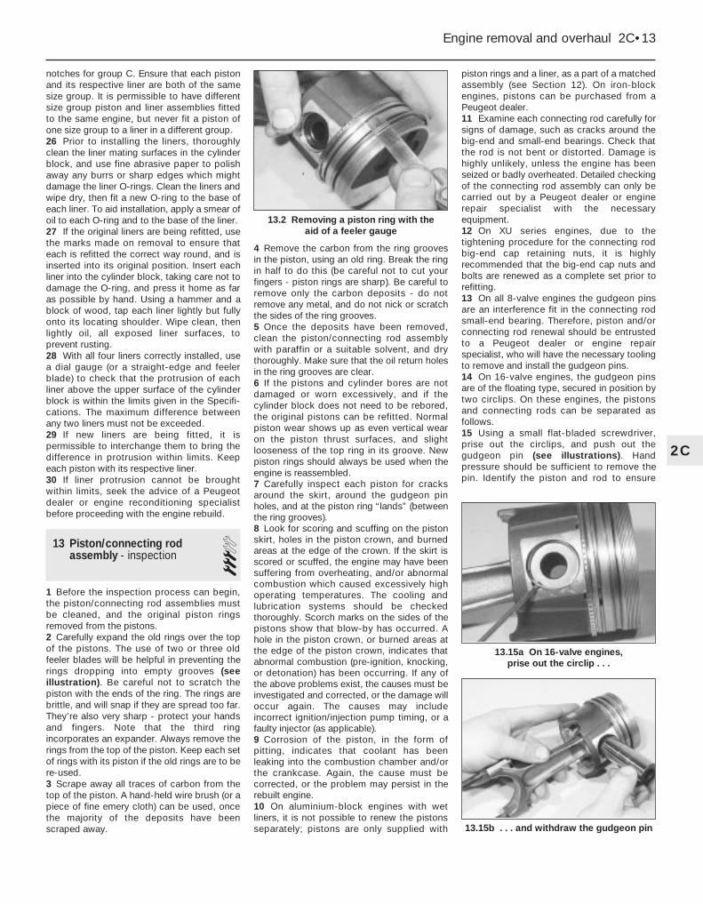
notches for group C. Ensure that each pistonand its respective liner are both of the samesize group. It is permissible to have differentsize group piston and liner assemblies fittedto the same engine, but never fit a piston ofone size group to a liner in a different group.26 Prior to installing the liners, thoroughlyclean the liner mating surfaces in the cylinderblock, and use fine abrasive paper to polishaway any burrs or sharp edges which mightdamage the liner O-rings. Clean the liners andwipe dry, then fit a new O-ring to the base ofeach liner. To aid installation, apply a smear ofoil to each O-ring and to the base of the liner.27 If the original liners are being refitted, usethe marks made on removal to ensure thateach is refitted the correct way round, and isinserted into its original position. Insert eachliner into the cylinder block, taking care not todamage the O-ring, and press it home as faras possible by hand. Using a hammer and ablock of wood, tap each liner lightly but fullyonto its locating shoulder. Wipe clean, thenlightly oil, all exposed liner surfaces, toprevent rusting.28 With all four liners correctly installed, usea dial gauge (or a straight-edge and feelerblade) to check that the protrusion of eachliner above the upper surface of the cylinderblock is within the limits given in the Specifi-cations. The maximum difference betweenany two liners must not be exceeded.29 If new liners are being fitted, it ispermissible to interchange them to bring thedifference in protrusion within limits. Keepeach piston with its respective liner.30 If liner protrusion cannot be broughtwithin limits, seek the advice of a Peugeotdealer or engine reconditioning specialistbefore proceeding with the engine rebuild.
13 Piston/connecting rodassembly - inspection 3
1 Before the inspection process can begin,the piston/connecting rod assemblies mustbe cleaned, and the original piston ringsremoved from the pistons.2 Carefully expand the old rings over the topof the pistons. The use of two or three oldfeeler blades will be helpful in preventing therings dropping into empty grooves (seeillustration). Be careful not to scratch thepiston with the ends of the ring. The rings arebrittle, and will snap if they are spread too far.They’re also very sharp - protect your handsand fingers. Note that the third ringincorporates an expander. Always remove therings from the top of the piston. Keep each setof rings with its piston if the old rings are to bere-used.3 Scrape away all traces of carbon from thetop of the piston. A hand-held wire brush (or apiece of fine emery cloth) can be used, oncethe majority of the deposits have beenscraped away.
4 Remove the carbon from the ring groovesin the piston, using an old ring. Break the ringin half to do this (be careful not to cut yourfingers - piston rings are sharp). Be careful toremove only the carbon deposits - do notremove any metal, and do not nick or scratchthe sides of the ring grooves.5 Once the deposits have been removed,clean the piston/connecting rod assemblywith paraffin or a suitable solvent, and drythoroughly. Make sure that the oil return holesin the ring grooves are clear.6 If the pistons and cylinder bores are notdamaged or worn excessively, and if thecylinder block does not need to be rebored,the original pistons can be refitted. Normalpiston wear shows up as even vertical wearon the piston thrust surfaces, and slightlooseness of the top ring in its groove. Newpiston rings should always be used when theengine is reassembled.7 Carefully inspect each piston for cracksaround the skirt, around the gudgeon pinholes, and at the piston ring “lands” (betweenthe ring grooves).8 Look for scoring and scuffing on the pistonskirt, holes in the piston crown, and burnedareas at the edge of the crown. If the skirt isscored or scuffed, the engine may have beensuffering from overheating, and/or abnormalcombustion which caused excessively highoperating temperatures. The cooling andlubrication systems should be checkedthoroughly. Scorch marks on the sides of thepistons show that blow-by has occurred. Ahole in the piston crown, or burned areas atthe edge of the piston crown, indicates thatabnormal combustion (pre-ignition, knocking,or detonation) has been occurring. If any ofthe above problems exist, the causes must beinvestigated and corrected, or the damage willoccur again. The causes may includeincorrect ignition/injection pump timing, or afaulty injector (as applicable).9 Corrosion of the piston, in the form ofpitting, indicates that coolant has beenleaking into the combustion chamber and/orthe crankcase. Again, the cause must becorrected, or the problem may persist in therebuilt engine.10 On aluminium-block engines with wetliners, it is not possible to renew the pistonsseparately; pistons are only supplied with
piston rings and a liner, as a part of a matchedassembly (see Section 12). On iron-blockengines, pistons can be purchased from aPeugeot dealer.11 Examine each connecting rod carefully forsigns of damage, such as cracks around thebig-end and small-end bearings. Check thatthe rod is not bent or distorted. Damage ishighly unlikely, unless the engine has beenseized or badly overheated. Detailed checkingof the connecting rod assembly can only becarried out by a Peugeot dealer or enginerepair specialist with the necessaryequipment.12 On XU series engines, due to thetightening procedure for the connecting rodbig-end cap retaining nuts, it is highlyrecommended that the big-end cap nuts andbolts are renewed as a complete set prior torefitting.13 On all 8-valve engines the gudgeon pinsare an interference fit in the connecting rodsmall-end bearing. Therefore, piston and/orconnecting rod renewal should be entrustedto a Peugeot dealer or engine repairspecialist, who will have the necessary toolingto remove and install the gudgeon pins.14 On 16-valve engines, the gudgeon pinsare of the floating type, secured in position bytwo circlips. On these engines, the pistonsand connecting rods can be separated asfollows.15 Using a small flat-bladed screwdriver,prise out the circlips, and push out thegudgeon pin (see illustrations). Handpressure should be sufficient to remove thepin. Identify the piston and rod to ensure
Engine removal and overhaul 2C•13
13.2 Removing a piston ring with the aid of a feeler gauge
2C
13.15a On 16-valve engines, prise out the circlip . . .
13.15b . . . and withdraw the gudgeon pin

correct reassembly. Discard the circlips - newones must be used on refitting.16 Examine the gudgeon pin and connectingrod small-end bearing for signs of wear ordamage. Wear can be cured by renewing boththe pin and bush. Bush renewal, however, is aspecialist job - press facilities are required,and the new bush must be reamed accurately.17 The connecting rods themselves shouldnot be in need of renewal, unless seizure orsome other major mechanical failure hasoccurred. Check the alignment of theconnecting rods visually, and if the rods arenot straight, take them to an engine overhaulspecialist for a more detailed check.18 Examine all components, and obtain anynew parts from your Peugeot dealer. If newpistons are purchased, they will be suppliedcomplete with gudgeon pins and circlips.Circlips can also be purchased individually.19 Position the piston so that the arrow onthe piston crown is positioned as shown inrelation to the connecting rod big-end bearingshell cutouts (see illustration). Apply a smearof clean engine oil to the gudgeon pin. Slide itinto the piston and through the connectingrod small-end. Check that the piston pivotsfreely on the rod, then secure the gudgeon pinin position with two new circlips. Ensure thateach circlip is correctly located in its groove inthe piston.
14 Crankshaft - inspection 2Checking crankshaft endfloat1 If the crankshaft endfloat is to be checked,this must be done when the crankshaft is stillinstalled in the cylinder block/crankcase, butis free to move (see Section 11).2 Check the endfloat using a dial gauge incontact with the end of the crankshaft. Pushthe crankshaft fully one way, and then zerothe gauge. Push the crankshaft fully the otherway, and check the endfloat. The result canbe compared with the specified amount, andwill give an indication as to whether newthrustwashers are required (see illustration).3 If a dial gauge is not available, feeler bladescan be used. First push the crankshaft fullytowards the flywheel/driveplate end of theengine, then use feeler blades to measure thegap between the web of No 2 crankpin andthe thrustwasher (see illustration).
Inspection4 Clean the crankshaft using paraffin or asuitable solvent, and dry it, preferably withcompressed air if available. Be sure to cleanthe oil holes with a pipe cleaner or similarprobe, to ensure that they are not obstructed.
5 Check the main and big-end bearingjournals for uneven wear, scoring, pitting andcracking.6 Big-end bearing wear is accompanied bydistinct metallic knocking when the engine isrunning (particularly noticeable when theengine is pulling from low speed) and someloss of oil pressure.7 Main bearing wear is accompanied bysevere engine vibration and rumble - gettingprogressively worse as engine speedincreases - and again by loss of oil pressure.8 Check the bearing journal for roughness byrunning a finger lightly over the bearingsurface. Any roughness (which will beaccompanied by obvious bearing wear)indicates that the crankshaft requiresregrinding (where possible) or renewal.9 If the crankshaft has been reground, checkfor burrs around the crankshaft oil holes (theholes are usually chamfered, so burrs shouldnot be a problem unless regrinding has beencarried out carelessly). Remove any burrs witha fine file or scraper, and thoroughly clean theoil holes as described previously.10 Using a micrometer, measure thediameter of the main and big-end bearingjournals, and compare the results with theSpecifications (see illustration). Bymeasuring the diameter at a number of pointsaround each journal’s circumference, you willbe able to determine whether or not thejournal is out-of-round. Take themeasurement at each end of the journal, nearthe webs, to determine if the journal istapered. Compare the results obtained withthose given in the Specifications. Where nospecified journal diameters are quoted, seekthe advice of a Peugeot dealer.11 Check the oil seal contact surfaces ateach end of the crankshaft for wear anddamage. If the seal has worn a deep groove inthe surface of the crankshaft, consult anengine overhaul specialist; repair may bepossible, but otherwise a new crankshaft willbe required.12 At the time of writing, it was not clearwhether Peugeot produce oversize bearingshells for all of these engines. On someengines, if the crankshaft journals have notalready been reground, it may be possible tohave the crankshaft reconditioned, and to fit
14.10 Measuring a crankshaft big-endjournal diameter
2C•14 Engine removal and overhaul
13.15c Piston and connecting rodcomponents
14.3 Checking crankshaft endfloat using feeler gauges
14.2 Checking crankshaft endfloat using a dial gauge
13.19 On 16-valve engines, on refittingensure that the piston arrow is positionedas shown, in relation to the connecting rod
bearing shell cutout (a)
Warning: Wear eye protectionwhen using compressed air!

undersize shells (see Section 18). If noundersize shells are available and thecrankshaft has worn beyond the specifiedlimits, it will have to be renewed. Consult yourPeugeot dealer or engine specialist for furtherinformation on parts availability.
15 Main and big-end bearings -inspection 2
1 Even though the main and big-end bearingsshould be renewed during the engineoverhaul, the old bearings should be retainedfor close examination, as they may revealvaluable information about the condition ofthe engine. The bearing shells are graded bythickness, the grade of each shell beingindicated by the colour code marked on it.2 Bearing failure can occur due to lack oflubrication, the presence of dirt or otherforeign particles, overloading the engine, orcorrosion (see illustration). Regardless of thecause of bearing failure, the cause must becorrected (where applicable) before theengine is reassembled, to prevent it fromhappening again.3 When examining the bearing shells, removethem from the cylinder block/crankcase, themain bearing ladder/caps (as appropriate), theconnecting rods and the connecting rod big-end bearing caps. Lay them out on a cleansurface in the same general position as theirlocation in the engine. This will enable you tomatch any bearing problems with thecorresponding crankshaft journal. Do nottouch any shell’s bearing surface with yourfingers while checking it, or the delicatesurface may be scratched.4 Dirt and other foreign matter gets into theengine in a variety of ways. It may be left inthe engine during assembly, or it may passthrough filters or the crankcase ventilationsystem. It may get into the oil, and from thereinto the bearings. Metal chips from machiningoperations and normal engine wear are oftenpresent. Abrasives are sometimes left inengine components after reconditioning,especially when parts are not thoroughlycleaned using the proper cleaning methods.Whatever the source, these foreign objectsoften end up embedded in the soft bearingmaterial, and are easily recognised. Largeparticles will not embed in the bearing, andwill score or gouge the bearing and journal.The best prevention for this cause of bearingfailure is to clean all parts thoroughly, andkeep everything spotlessly-clean duringengine assembly. Frequent and regular engineoil and filter changes are also recommended.5 Lack of lubrication (or lubricationbreakdown) has a number of interrelatedcauses. Excessive heat (which thins the oil),overloading (which squeezes the oil from thebearing face) and oil leakage (from excessivebearing clearances, worn oil pump or highengine speeds) all contribute to lubrication
breakdown. Blocked oil passages, whichusually are the result of misaligned oil holes ina bearing shell, will also oil-starve a bearing,and destroy it. When lack of lubrication is thecause of bearing failure, the bearing materialis wiped or extruded from the steel backing ofthe bearing. Temperatures may increase tothe point where the steel backing turns bluefrom overheating.6 Driving habits can have a definite effect onbearing life. Full-throttle, low-speed operation(labouring the engine) puts very high loads onbearings, tending to squeeze out the oil film.These loads cause the bearings to flex, whichproduces fine cracks in the bearing face(fatigue failure). Eventually, the bearingmaterial will loosen in pieces, and tear awayfrom the steel backing.7 Short-distance driving leads to corrosion ofbearings, because insufficient engine heat isproduced to drive off the condensed waterand corrosive gases. These products collectin the engine oil, forming acid and sludge. Asthe oil is carried to the engine bearings, theacid attacks and corrodes the bearingmaterial.8 Incorrect bearing installation during engineassembly will lead to bearing failure as well.Tight-fitting bearings leave insufficient bearingrunning clearance, and will result in oilstarvation. Dirt or foreign particles trappedbehind a bearing shell result in high spots onthe bearing, which lead to failure.9 Do not touch any shell’s bearing surfacewith your fingers during reassembly; there is arisk of scratching the delicate surface, or ofdepositing particles of dirt on it.10 As mentioned at the beginning of thisSection, the bearing shells should be renewedas a matter of course during engine overhaul;to do otherwise is false economy. Refer toSection 18 for details of bearing shellselection.
16 Engine overhaul - reassemblysequence
1 Before reassembly begins, ensure that allnew parts have been obtained, and that allnecessary tools are available. Read throughthe entire procedure carefully to familiariseyourself with the work involved, and to ensurethat all items necessary for reassembly of theengine are at hand. In addition to all normaltools and materials, thread-locking compoundwill be needed. A suitable tube of liquidsealant will also be required for the joint facesthat are fitted without gaskets. It isrecommended that Peugeot’s own product(s)are used, which are specially formulated forthis purpose.2 In order to save time and avoid problems,engine reassembly can be carried out in thefollowing order:
a) Crankshaft (Section 18).b) Piston/connecting rod assemblies
(Section 19).c) Oil pump .d) Sump (See Part A or B - as applicable).e) Flywheel (See Part A or B - as applicable).f) Cylinder head (See Part A or B - as
applicable).g) Timing belt tensioner and sprockets, and
timing belt (See Part A or B - asapplicable).
h) Engine external components.
3 At this stage, all engine components shouldbe absolutely clean and dry, with all faultsrepaired. The components should be laid out(or in individual containers) on a completelyclean work surface.
17 Piston rings - refitting 31 Before fitting new piston rings, the ring endgaps must be checked as follows.2 Lay out the piston/connecting rodassemblies and the new piston ring sets, sothat the ring sets will be matched with thesame piston and cylinder during the end gapmeasurement and subsequent enginereassembly.3 Insert the top ring into the first cylinder, andpush it down the bore using the top of thepiston. This will ensure that the ring remainssquare with the cylinder walls. Position thering near the bottom of the cylinder bore, atthe lower limit of ring travel. Note that the topand second compression rings are different.The second ring is easily identified by the stepon its lower surface, and by the fact that itsouter face is tapered.4 Measure the end gap using feeler blades.5 Repeat the procedure with the ring at thetop of the cylinder bore, at the upper limit ofits travel, and compare the measurements
Engine removal and overhaul 2C•15
15.2 Typical bearing failures
2C

with the figures given in the Specifications(see illustration). Where no figures are given,seek the advice of a Peugeot dealer or enginereconditioning specialist.6 If the gap is too small (unlikely if genuinePeugeot parts are used), it must be enlarged,or the ring ends may contact each otherduring engine operation, causing seriousdamage. Ideally, new piston rings providingthe correct end gap should be fitted. As a lastresort, the end gap can be increased by filingthe ring ends very carefully with a fine file.Mount the file in a vice equipped with softjaws, slip the ring over the file with the endscontacting the file face, and slowly move thering to remove material from the ends. Takecare, as piston rings are sharp, and are easilybroken.7 With new piston rings, it is unlikely that theend gap will be too large. If the gaps are toolarge, check that you have the correct ringsfor your engine and for the particular cylinderbore size.8 Repeat the checking procedure for eachring in the first cylinder, and then for the ringsin the remaining cylinders. Remember to keeprings, pistons and cylinders matched up.9 Once the ring end gaps have been checkedand if necessary corrected, the rings can befitted to the pistons.10 Fit the piston rings using the sametechnique as for removal. Fit the bottom (oilcontrol) ring first, and work up. When fittingthe oil control ring, first insert the expander(where fitted), then fit the ring with its gappositioned 180° from the expander gap.Ensure that the second compression ring isfitted the correct way up, with its identificationmark (either a dot of paint or the word “TOP”stamped on the ring surface) at the top, andthe stepped surface at the bottom (seeillustration). Arrange the gaps of the top andsecond compression rings 120° either side ofthe oil control ring gap. Note: Always followany instructions supplied with the new pistonring sets - different manufacturers may specifydifferent procedures. Do not mix up the topand second compression rings, as they havedifferent cross-sections.
18 Crankshaft - refitting andmain bearing runningclearance check
4Selection of new bearing shellsTU series engine1 On early engines, both upper and lowermain bearing shells were of the samethickness, with only two sizes of bearingshells being available: a standard size for usewith the standard crankshaft, and a set ofoversize bearing shells for use once thecrankshaft bearing journals have beenreground.2 However, since February 1992, thespecified main bearing running clearance hasbeen significantly reduced. This has beenachieved by the introduction of three differentgrades of bearing shell, in both standard sizesand oversizes. The grades are indicated by acolour-coding marked on the edge of eachshell, which denotes the shell’s thickness, aslisted in the following table. The upper shell onall bearings is of the same size (class B,colour code black), and the running clearanceis controlled by fitting a lower bearing shell of
the required thickness. This arrangement hasbeen fitted to all engines produced sinceFebruary 1992 and, if possible, should also befitted to earlier engines during overhaul. Seekthe advice of your Peugeot dealer on partsavailability and the best course of action whenordering new bearing shells.
Aluminium block engineBearing Thickness (mm)colour code Standard UndersizeBlue (class A) 1.823 1.973Black (class B) 1.835 1.985Green (class C) 1.848 1.998
Cast-iron block engine Bearing Thickness (mm)colour code Standard UndersizeBlue (class A) 1.844 1.994Black (class B) 1.858 2.008Green (class C) 1.869 2.019
3 On early engines, the correct size of bearingshell must be selected by measuring therunning clearance as described under thesub-heading below.4 On engines produced since February 1992,when the new bearing shell sizes wereintroduced, the crankshaft and cylinderblock/crankcase have reference marks onthem, to identify the size of the journals andbearing bores.5 The cylinder block reference marks are onthe right-hand (timing belt) end of the block,and the crankshaft reference marks are on theright-hand (timing belt) end of the crankshaft,on the right-hand web of No 4 crankpin (seeillustration). These marks can be used toselect bearing shells of the required thicknessas follows.6 On both the crankshaft and block there aretwo lines of identification: a bar code, which isused by Peugeot during production, and arow of five letters. The first letter in thesequence refers to the size of No 1 bearing (atthe flywheel/driveplate end). The last letter inthe sequence (which is followed by an arrow)refers to the size of No 5 main bearing. Thesemarks can be used to select the requiredbearing shell grade as follows.7 Obtain the identification letter of both therelevant crankshaft journal and the cylinderblock bearing bore. Noting that the cylinder
2C•16 Engine removal and overhaul
17.5 Measuring a piston ring end gap
1 Oil control ring2 Second compression ring3 Top compression ring
17.10 Piston ring fitting diagram (typical)
18.5 Cylinder block and crankshaft mainbearing reference marking locations -
TU series engines

block letters are listed across the top of thechart, and the crankshaft letters down theside, trace a vertical line down from therelevant cylinder block letter, and a horizontalline across from the relevant crankshaft letter,and find the point at which both lines cross.This crossover point will indicate the grade oflower bearing shell required to give thecorrect main bearing running clearance. Forexample, the illustration shows cylinder blockreference G, and crankshaft reference T,crossing at a point within the area of Class A,indicating that a blue-coded (Class A) lowerbearing shell is required to give the correctmain bearing running clearance (seeillustration).8 Repeat this procedure so that the requiredbearing shell grade is obtained for each of thefive main bearing journals.
XU series engine9 On some early engines, both the upper andlower bearing shells were of the samethickness.10 However, on later engines the mainbearing running clearance was significantlyreduced. To enable this to be done, fourdifferent grades of bearing shell wereintroduced. The grades are indicated by acolour-coding marked on the edge of eachshell, which denotes the shell’s thickness, aslisted in the following table. The upper shell onall bearings is of the same size, and therunning clearance is controlled by fitting alower bearing shell of the required thickness.Note: On all XU series engines, upper shellsare easily distinguished from lower shells, bytheir grooved bearing surface; the lower shellshave a plain surface. It was not clear at the time of writing whether undersize bearingshells are available for 1998 cc engine. Referto your Peugeot dealer for the latestinformation.
1580 cc, 1761 cc and 1905 cc enginesBearing colour Thickness (mm)code Standard UndersizeUpper bearing:
Yellow 1.856 2.006Lower bearing:
Blue (Class A) 1.836 1.986Black (Class B) 1.848 1.998Green (Class C) 1.859 2.009Red (Class D) 1.870 2.020
1998 cc enginesBearing colour Thickness (mm)code Standard UndersizeUpper bearing:
Black 1.847 N/ALower bearing:
Blue (Class A) 1.844 N/ABlack (Class B) 1.857 N/AGreen (Class C) 1.866 N/ARed (Class D) 1.877 N/A
11 On most later engines, new bearing shellscan be selected using the reference marks onthe cylinder block/crankcase. The cylinderblock marks identify the diameter of thebearing bores, and the crankshaft marks thediameter of the crankshaft journals. Where nomarks are present, the bearing shells can onlybe selected by checking the runningclearance (see below).12 The cylinder block reference marks are onthe left-hand (flywheel/driveplate) end of theblock, and the crankshaft reference marks areon the end web of the crankshaft (seeillustration). These marks can be used toselect bearing shells of the required thicknessas follows.13 On both the crankshaft and block thereare two lines of identification: a bar code,which is used by Peugeot during production,and a row of five letters. The first letter in thesequence refers to the size of No 1 bearing (at
the flywheel/driveplate end). The last letter inthe sequence (which is followed by an arrow)refers to the size of No 5 main bearing. Thesemarks can be used to select the requiredbearing shell grade as follows.14 Obtain the identification number/letter ofboth the relevant crankshaft journal and thecylinder block bearing bore. Noting that thecrankshaft references are listed across thetop of the chart, and the cylinder blockreferences down the side, trace a vertical linedown from the relevant crankshaft reference,and a horizontal line across from the relevantcylinder block reference, and find the point atwhich both lines cross. This crossover pointwill indicate the grade of lower bearing shellrequired to give the correct main bearingrunning clearance. For example, theillustration shows crankshaft reference 6, andcylinder block reference H, crossing at a pointwithin the RED area, indicating that a Red-coded (Class D) lower bearing shell is requiredto give the correct main bearing runningclearance (see illustration).15 Repeat this procedure so that therequired bearing shell grade is obtained foreach of the five main bearing journals.16 Seek the advice of your Peugeot dealeron parts availability, and on the best course ofaction when ordering new bearing shells.Note: On early models, at overhaul it isrecommended that the later bearing shellarrangement is fitted. This, however, shouldonly be done if the lubrication systemcomponents are upgraded (necessitatingreplacement of the oil pump relief valve pistonand spring as well as the pump sprocket and
Engine removal and overhaul 2C•17
A Bar Code (for production use only)B Reference marks
18.12 Cylinder block and crankshaft mainbearing reference marking locations -
XU series engines
18.7 Main bearing shell selection chart, for use with TU series engines - see text for further information
2C

drive chain) at the same time. If the newbearing arrangement is to be used withoutuprating the lubrication system, Peugeot statethat Blue (Class A) lower bearing shells shouldbe fitted. Refer to your Peugeot dealer forfurther information.17 Since there are no bearing identificationmarks, the relevant main bearing shell grademust be selected by measuring the mainbearing running clearance.
Main bearing running clearance checkTU series engine18 On early engines, if the modified bearingshells are to be fitted, obtain a set of newblack (Class B) upper bearing shells and newblue (Class A) lower bearing shells. On later(February 1992-on) engines where themodified bearing shells are already fitted, therunning clearance check can be carried outusing the original bearing shells. However, it ispreferable to use a new set, since the resultsobtained will be more conclusive.19 Clean the backs of the bearing shells, andthe bearing locations in both the cylinderblock/crankcase and the main bearing ladder.20 Press the bearing shells into theirlocations, ensuring that the tab on each shellengages in the notch in the cylinder
block/crankcase or main bearing ladderlocation. Take care not to touch any shell’sbearing surface with your fingers. Note thatthe grooved bearing shells, both upper andlower, are fitted to Nos 2 and 4 main bearings(see illustration). If the original bearing shellsare being used for the check, ensure that theyare refitted in their original locations. Theclearance can be checked in either of twoways.21 One method (which will be difficult toachieve without a range of internalmicrometers or internal/external expandingcalipers) is to refit the main bearing laddercasting to the cylinder block/crankcase, withthe bearing shells in place. With the castingretaining bolts correctly tightened, measurethe internal diameter of each assembled pairof bearing shells. If the diameter of eachcorresponding crankshaft journal is measuredand then subtracted from the bearing internaldiameter, the result will be the main bearingrunning clearance.22 The second (and more accurate) methodis to use a product known as “Plastigauge”.This consists of a fine thread of perfectly-round plastic, which is compressed betweenthe bearing shell and the journal. When theshell is removed, the plastic is deformed, andcan be measured with a special card gauge
supplied with the kit. The running clearance isdetermined from this gauge. Plastigaugeshould be available from your Peugeot dealer,otherwise enquiries at one of the largerspecialist motor factors should produce thename of a stockist in your area. Theprocedure for using Plastigauge is as follows.23 With the main bearing upper shells inplace, carefully lay the crankshaft in position.Do not use any lubricant; the crankshaftjournals and bearing shells must be perfectlyclean and dry.24 Cut several lengths of the appropriate-size Plastigauge (they should be slightlyshorter than the width of the main bearings),and place one length on each crankshaftjournal axis (see illustration).25 With the main bearing lower shells inposition, refit the main bearing ladder casting,tightening its retaining bolts as described inparagraph 45. Take care not to disturb thePlastigauge, and do not rotate the crankshaftat any time during this operation.26 Remove the main bearing ladder casting,again taking great care not to disturb thePlastigauge or rotate the crankshaft.27 Compare the width of the crushedPlastigauge on each journal to the scaleprinted on the Plastigauge envelope, to obtainthe main bearing running clearance (seeillustration). Compare the clearancemeasured with that given in the Specificationsat the start of this Chapter.28 If the clearance is significantly differentfrom that expected, the bearing shells may bethe wrong size (or excessively worn, if theoriginal shells are being re-used). Beforedeciding that different-size shells are required,make sure that no dirt or oil was trappedbetween the bearing shells and the caps orblock when the clearance was measured. Ifthe Plastigauge was wider at one end than atthe other, the crankshaft journal may betapered.29 If the clearance is not as specified, usethe reading obtained, along with the shellthicknesses quoted above, to calculate thenecessary grade of bearing shells required.When calculating the bearing clearancerequired, bear in mind that it is always betterto have the running clearance towards the
2C•18 Engine removal and overhaul
18.14 Main bearing shell selection chart, for use with XU series engines - see text for further information
18.20 On TU series engines, note that thegrooved bearing shells are fitted to Nos 2 and 4 main bearing journals
18.27 Measuring the width of thedeformed Plastigauge using the scale on
the card provided
18.24 Plastigauge in place on a crankshaftmain bearing journal
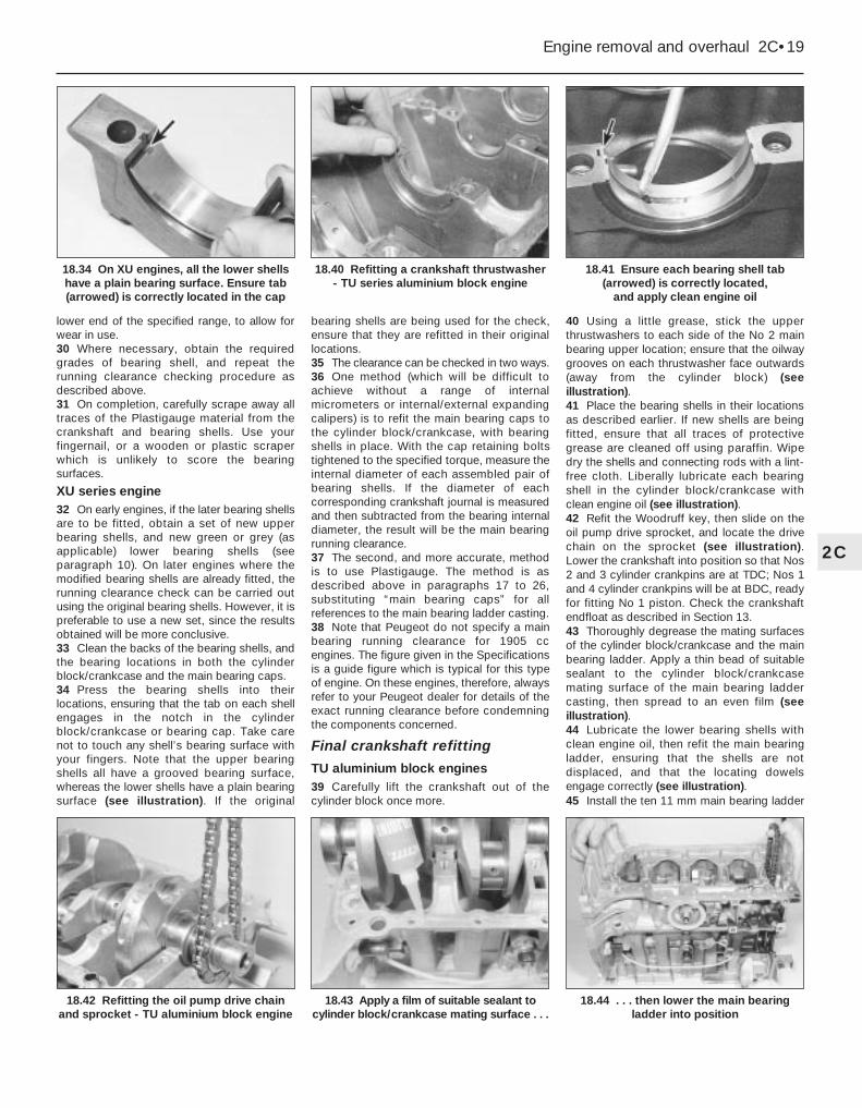
lower end of the specified range, to allow forwear in use.30 Where necessary, obtain the requiredgrades of bearing shell, and repeat therunning clearance checking procedure asdescribed above.31 On completion, carefully scrape away alltraces of the Plastigauge material from thecrankshaft and bearing shells. Use yourfingernail, or a wooden or plastic scraperwhich is unlikely to score the bearingsurfaces.
XU series engine32 On early engines, if the later bearing shellsare to be fitted, obtain a set of new upperbearing shells, and new green or grey (asapplicable) lower bearing shells (seeparagraph 10). On later engines where themodified bearing shells are already fitted, therunning clearance check can be carried outusing the original bearing shells. However, it ispreferable to use a new set, since the resultsobtained will be more conclusive.33 Clean the backs of the bearing shells, andthe bearing locations in both the cylinderblock/crankcase and the main bearing caps.34 Press the bearing shells into theirlocations, ensuring that the tab on each shellengages in the notch in the cylinderblock/crankcase or bearing cap. Take carenot to touch any shell’s bearing surface withyour fingers. Note that the upper bearingshells all have a grooved bearing surface,whereas the lower shells have a plain bearingsurface (see illustration). If the original
bearing shells are being used for the check,ensure that they are refitted in their originallocations.35 The clearance can be checked in two ways.36 One method (which will be difficult toachieve without a range of internalmicrometers or internal/external expandingcalipers) is to refit the main bearing caps tothe cylinder block/crankcase, with bearingshells in place. With the cap retaining boltstightened to the specified torque, measure theinternal diameter of each assembled pair ofbearing shells. If the diameter of eachcorresponding crankshaft journal is measuredand then subtracted from the bearing internaldiameter, the result will be the main bearingrunning clearance.37 The second, and more accurate, methodis to use Plastigauge. The method is asdescribed above in paragraphs 17 to 26,substituting “main bearing caps” for allreferences to the main bearing ladder casting.38 Note that Peugeot do not specify a mainbearing running clearance for 1905 ccengines. The figure given in the Specificationsis a guide figure which is typical for this typeof engine. On these engines, therefore, alwaysrefer to your Peugeot dealer for details of theexact running clearance before condemningthe components concerned.
Final crankshaft refitting
TU aluminium block engines39 Carefully lift the crankshaft out of thecylinder block once more.
40 Using a little grease, stick the upperthrustwashers to each side of the No 2 mainbearing upper location; ensure that the oilwaygrooves on each thrustwasher face outwards(away from the cylinder block) (seeillustration).41 Place the bearing shells in their locationsas described earlier. If new shells are beingfitted, ensure that all traces of protectivegrease are cleaned off using paraffin. Wipedry the shells and connecting rods with a lint-free cloth. Liberally lubricate each bearingshell in the cylinder block/crankcase withclean engine oil (see illustration).42 Refit the Woodruff key, then slide on theoil pump drive sprocket, and locate the drivechain on the sprocket (see illustration).Lower the crankshaft into position so that Nos2 and 3 cylinder crankpins are at TDC; Nos 1and 4 cylinder crankpins will be at BDC, readyfor fitting No 1 piston. Check the crankshaftendfloat as described in Section 13.43 Thoroughly degrease the mating surfacesof the cylinder block/crankcase and the mainbearing ladder. Apply a thin bead of suitablesealant to the cylinder block/crankcasemating surface of the main bearing laddercasting, then spread to an even film (seeillustration).44 Lubricate the lower bearing shells withclean engine oil, then refit the main bearingladder, ensuring that the shells are notdisplaced, and that the locating dowelsengage correctly (see illustration).45 Install the ten 11 mm main bearing ladder
Engine removal and overhaul 2C•19
18.41 Ensure each bearing shell tab(arrowed) is correctly located,
and apply clean engine oil
18.44 . . . then lower the main bearingladder into position
18.43 Apply a film of suitable sealant tocylinder block/crankcase mating surface . . .
18.42 Refitting the oil pump drive chainand sprocket - TU aluminium block engine
18.40 Refitting a crankshaft thrustwasher- TU series aluminium block engine
18.34 On XU engines, all the lower shellshave a plain bearing surface. Ensure tab(arrowed) is correctly located in the cap
2C

retaining bolts, and tighten them all by handonly. Working progressively outwards fromthe centre bolts, tighten the ten bolts, by aturn at a time, to the specified Stage 1 torquewrench setting. Once all the bolts have beentightened to the Stage 1 setting, angle-tightenthe bolts through the specified Stage 2 angleusing a socket and extension bar. It isrecommended that an angle-measuringgauge is used during this stage of thetightening, to ensure accuracy (seeillustrations). If a gauge is not available, use adab of white paint to make alignment marksbetween the bolt head and casting prior totightening; the marks can then be used tocheck that the bolt has been rotatedsufficiently during tightening.46 Refit all the 6 mm bolts securing the mainbearing ladder to the base of the cylinderblock, and tighten them to the specifiedtorque. Check that the crankshaft rotatesfreely.47 Refit the piston/connecting rodassemblies to the crankshaft as described inSection 18.48 Ensuring that the drive chain is correctlylocated on the sprocket, refit the oil pump andsump as described in Part A of this Chapter.49 Fit two new crankshaft oil seals asdescribed in Part A.50 Refit the flywheel as described in Part A ofthis Chapter.51 Where removed, refit the cylinder head asdescribed in Part A. Also refit the crankshaftsprocket and timing belt as described in Part A.
TU series cast-iron block engine52 Carefully lift the crankshaft out of thecylinder block once more.53 Using a little grease, stick the upperthrustwashers to each side of No 2 mainbearing upper location. Ensure the oilwaygrooves on each thrustwasher face outwards(away from the cylinder block) (see illustration).54 Place the bearing shells in their locationsas described earlier (see illustration). If newshells are being fitted, ensure that all traces ofprotective grease are cleaned off usingparaffin. Wipe dry the shells and connectingrods with a lint-free cloth. Liberally lubricateeach bearing shell in the cylinder block/crankcase and cap with clean engine oil.55 Lower the crankshaft into position so thatNos 2 and 3 cylinder crankpins are at TDC;Nos 1 and 4 cylinder crankpins will be at BDC,ready for fitting No 1 piston. Check thecrankshaft endfloat, referring to Section 14.56 Lubricate the lower bearing shells in themain bearing caps with clean engine oil. Makesure that the locating lugs on the shellsengage with the corresponding recesses inthe caps.57 Fit the main bearing caps to their correctlocations, ensuring that they are fitted thecorrect way round (the bearing shell lugrecesses in the block and caps must be onthe same side). Insert the bolts loosely.58 Tighten the main bearing cap bolts to thespecified Stage 1 torque wrench setting.Once all the bolts have been tightened to theStage 1 setting, angle-tighten the boltsthrough the specified Stage 2 angle, using asocket and extension bar. It is recommended
that an angle-measuring gauge is used duringthis stage of the tightening, to ensureaccuracy. If a gauge is not available, use adab of white paint to make alignment marksbetween the bolt head and casting prior totightening; the marks can then be used tocheck that the bolt has been rotatedsufficiently during tightening.59 Check that the crankshaft rotates freely.60 Refit the piston/connecting rodassemblies to the crankshaft as described inSection 19.61 Refit the Woodruff key to the crankshaftgroove, and slide on the oil pump drivesprocket. Locate the drive chain on thesprocket.62 Ensure that the mating surfaces of frontoil seal housing and cylinder block are cleanand dry. Note the correct fitted depth of thefront oil seal then, using a large flat-bladedscrewdriver, lever the seal out of the housing.63 Apply a smear of suitable sealant to the oilseal housing mating surface, and make surethat the locating dowels are in position. Slidethe housing over the end of the crankshaft,and into position on the cylinder block.Tighten the housing retaining bolts securely.64 Repeat the operations in paragraphs 62and 63, and fit the rear oil seal housing.65 Fit a new front and rear crankshaft oil sealas described in Part A of this Chapter.66 Ensuring that the chain is correctlylocated on the drive sprocket, refit the oilpump and sump as described in Part A of thisChapter.67 Refit the flywheel (Part A of this Chapter).68 Where removed, refit the cylinder headand install the crankshaft sprocket and timingbelt - see the relevant Sections of Part A.
XU series engines69 Carry out the operations described abovein paragraphs 52 to 56.70 Fit main bearing caps Nos 2 to 5 to theircorrect locations, ensuring that they are fittedthe correct way round (the bearing shell tabrecesses in the block and caps must be onthe same side). Insert the bolts/nuts,tightening them only loosely at this stage.71 Apply a small amount of sealant to No 1main bearing cap face mating on the cylinderblock, around the sealing strip holes (seeillustration).
2C•20 Engine removal and overhaul
18.45a Tighten ten 11 mm main bearingbolts to the stage 1 torque setting . . .
18.53 Fitting a thrustwasher to No 2 main bearing upper location
18.71 Applying sealant to the cylinderblock No 1 main bearing cap mating face
18.54 Ensure tab (arrowed) is located inthe cap when fitting the bearing shells
18.45b . . . then angle-tighten themthrough the specified stage 2 angle

72 Locate the tab of each sealing strip overthe pins on the base of No 1 bearing cap, andpress the strips into the bearing cap grooves.It is now necessary to obtain two thin metalstrips, of 0.25 mm thickness or less, in orderto prevent the strips moving when the cap isbeing fitted. Peugeot garages use the toolshown, which acts as a clamp. Metal strips(such as old feeler blades) can be used,provided all burrs which may damage thesealing strips are first removed (seeillustrations).73 Where applicable, oil both sides of themetal strips, and hold them on the sealingstrips. Fit the No 1 main bearing cap, insertthe bolts loosely, then carefully pull out themetal strips in a horizontal direction, using apair of pliers (see illustrations).74 Tighten all the main bearing capbolts/nuts evenly to the specified torque.Using a sharp knife, trim off the ends of theNo 1 bearing cap sealing strips, so that theyprotrude above the cylinder block/crankcasemating surface by approximately 1 mm (seeillustrations).75 On 1580 cc, 1761 cc and 1905 ccengines, refit the centre main bearing sideretaining bolts and sealing washers (one at thefront of the block, and one at the rear) andtighten them both to the specified torque.76 Fit a new crankshaft rear oil seal asdescribed in Part B of this Chapter.77 Refit the piston/connecting rodassemblies to the crankshaft as described inSection 19.
78 Refit the Woodruff key, then slide on theoil pump drive sprocket and spacer (wherefitted), and locate the drive chain on thesprocket.79 Ensure that the mating surfaces of thefront oil seal carrier and cylinder block areclean and dry. Note the correct fitted depth ofthe oil seal then, using a large flat-bladedscrewdriver, lever the old seal out of thehousing.80 Apply a smear of suitable sealant to the oilseal carrier mating surface. Ensure that thelocating dowels are in position, then slide thecarrier over the end of the crankshaft and intoposition on the cylinder block. Tighten thecarrier retaining bolts to the specified torque.81 Fit a new crankshaft front oil seal asdescribed in Part B of this Chapter.82 Ensuring that the drive chain is correctlylocated on the sprocket, refit the oil pump andsump -refer to Part B or C of this Chapter.83 Where removed, refit the rear timing coverand cylinder head as described in Part B.
19 Piston/connecting rodassembly - refitting and big-end bearing clearance check
4Selection of bearing shells1 On most engines, there are two sizes ofbig-end bearing shell produced by Peugeot; astandard size for use with the standardcrankshaft, and an oversize for use once thecrankshaft journals have been reground.
2 Consult your Peugeot dealer for the latestinformation on parts availability. To be safe,always quote the diameter of the crankshaftbig-end crankpins when ordering bearingshells.3 Prior to refitting the piston/connecting rodassemblies, the big-end bearing runningclearance should be checked as follows.
Big-end bearing running clearance check4 Clean the backs of the bearing shells, andthe bearing locations in both the connectingrod and bearing cap.5 Press the bearing shells into their locations,ensuring that the tab on each shell engages inthe notch in the connecting rod and cap. Takecare not to touch any shell’s bearing surfacewith your fingers (see illustration). If the
Engine removal and overhaul 2C•21
18.73a Fitting No 1 main bearing cap,using metal strips to retain the side seals
18.74b . . . then trim the sealing strips, sothat they protrude above the cylinder block
mating surface by approximately 1 mm
18.74a With all bearing caps correctlyinstalled, tighten their retaining nuts and
bolts to the specified torque . . .
18.73b Removing a metal strip from No 1main bearing cap using a pair of pliers
18.72b Using the Peugeot special tool tofit No 1 main bearing cap
18.72a Fitting a sealing strip to No 1 main bearing cap
2C
19.5 Fitting a bearing shell to a connectingrod - ensure tab (arrowed) engages with
the recess in the connecting rod

original bearing shells are being used for thecheck, ensure that they are refitted in theiroriginal locations. The clearance can bechecked in either of two ways.6 One method is to refit the big-end bearingcap to the connecting rod, ensuring that theyare fitted the correct way around (seeparagraph 20), with the bearing shells inplace. With the cap retaining nuts correctlytightened, use an internal micrometer orvernier caliper to measure the internaldiameter of each assembled pair of bearingshells. If the diameter of each correspondingcrankshaft journal is measured and thensubtracted from the bearing internal diameter,the result will be the big-end bearing runningclearance.7 The second, and more accurate, method isto use Plastigauge (see Section 18).8 Ensure that the bearing shells are correctlyfitted. Place a strand of Plastigauge on each(cleaned) crankpin journal.9 Refit the (clean) piston/connecting rodassemblies to the crankshaft, and refit thebig-end bearing caps, using the marks madeor noted on removal to ensure that they arefitted the correct way around.10 Tighten the bearing cap nuts as describedbelow in paragraph 21 or 22 (as applicable).Take care not to disturb the Plastigauge orrotate the connecting rod during thetightening sequence.11 Dismantle the assemblies without rotatingthe connecting rods. Use the scale printed onthe Plastigauge envelope to obtain the big-end bearing running clearance.12 If the clearance is significantly differentfrom that expected, the bearing shells may bethe wrong size (or excessively worn, if theoriginal shells are being re-used). Make surethat no dirt or oil was trapped between thebearing shells and the caps or block when theclearance was measured. If the Plastigaugewas wider at one end than at the other, thecrankshaft journal may be tapered.13 Note that Peugeot do not specify arecommended big-end bearing runningclearance. The figure given in the Specifica-tions is a guide figure, which is typical for this
type of engine. Before condemning thecomponents concerned, refer to your Peugeotdealer or engine reconditioning specialist forfurther information on the specified runningclearance. Their advice on the best course ofaction to be taken can then also be obtained.14 On completion, carefully scrape away alltraces of the Plastigauge material from thecrankshaft and bearing shells. Use yourfingernail, or some other object which isunlikely to score the bearing surfaces.
Final piston/connecting rodrefitting15 Note that the following procedureassumes that the cylinder liners (where fitted)are in position in the cylinder block/crankcaseas described in Section 12, and that thecrankshaft and main bearing ladder/caps arein place (see Section 18).16 Ensure that the bearing shells arecorrectly fitted as described earlier. If newshells are being fitted, ensure that all traces ofthe protective grease are cleaned off usingparaffin. Wipe dry the shells and connectingrods with a lint-free cloth.17 Lubricate the cylinder bores, the pistons,and piston rings, then lay out eachpiston/connecting rod assembly in itsrespective position.18 Start with assembly No 1. Make sure thatthe piston rings are still spaced as describedin Section 17, then clamp them in positionwith a piston ring compressor.19 Insert the piston/connecting rod assemblyinto the top of cylinder/liner No 1. On petrolengines, ensure that the arrow on the pistoncrown is pointing towards the timing belt endof the engine and on Diesel engines ensurethat the cloverleaf-shaped cut-out on thepiston crown is towards the front (oil filterside) of the cylinder block. Using a block ofwood or hammer handle against the pistoncrown, tap the assembly into the cylinder/lineruntil the piston crown is flush with the top ofthe cylinder/liner (see illustration).20 Ensure that the bearing shell is stillcorrectly installed. Liberally lubricate thecrankpin and both bearing shells. Taking carenot to mark the cylinder/liner bores, pull the
piston/connecting rod assembly down thebore and onto the crankpin. Refit the big-endbearing cap, tightening its retaining nutsfinger-tight at first. Note that the faces withthe identification marks must match (whichmeans that the bearing shell locating tabsabut each other). 21 On TU series engines, tighten the bearingcap retaining nuts evenly and progressively tothe specified torque setting.22 On XU series engines, tighten the bearingcap retaining nuts evenly and progressively tothe stage 1 torque setting. Fully slacken bothnuts, then tighten them to the stage 2 torquesetting. Once both nuts have been tightenedto the stage 2 setting, angle-tighten themthrough the specified stage 3 angle, using asocket and extension bar. It is recommendedthat an angle-measuring gauge is used duringthis stage of the tightening, to ensureaccuracy (see illustrations). If a gauge is notavailable, use a dab of white paint to makealignment marks between the nut and bearingcap prior to tightening; the marks can then beused to check that the nut has been rotatedsufficiently during tightening.23 On all engines, once the bearing capretaining nuts have been correctly tightened,rotate the crankshaft. Check that it turnsfreely; some stiffness is to be expected if newcomponents have been fitted, but thereshould be no signs of binding or tight spots.24 Refit the remaining three piston/connecting rod assemblies in the same way.25 Refit the cylinder head and oil pump asdescribed in Part A or B of this Chapter (asapplicable).
20 Engine - initial start-up after overhaul
1 With the engine refitted in the vehicle,double-check the engine oil and coolantlevels. Make a final check that everything hasbeen reconnected, and that there are no toolsor rags left in the engine compartment.2 Remove the spark plugs. On models with adistributor, disable the ignition system by
2C•22 Engine removal and overhaul
19.19 Tap the piston into the bore using ahammer handle
19.22b . . . then through the anglespecified for stage 3
19.22a On XU series engines, tighten thebig-end bearing cap nuts to the stage 1
specified torque, then fully slacken themand tighten them to the stage 2 torque . . .

disconnecting the ignition HT coil lead fromthe distributor cap, and earthing it on thecylinder block. Use a jumper lead or similarwire to make a good connection. On modelswith a static (distributorless) ignition system,disable the ignition system by disconnectingthe LT wiring connector from the ignition HTcoil, referring to Chapter 5B for information.3 Turn the engine on the starter until the oilpressure warning light goes out. Refit thespark plugs, and reconnect the spark plug(HT) leads, referring to Chapter 1 for furtherinformation. Reconnect any HT leads or wiringwhich was disconnected in paragraph 2.4 Start the engine, noting that this may take a
little longer than usual, due to the fuel systemcomponents having been disturbed.5 While the engine is idling, check for fuel,water and oil leaks. Don’t be alarmed if thereare some odd smells and smoke from partsgetting hot and burning off oil deposits. On16-valve engines, some valvegear noise maybe heard at first; this should disappear as theoil circulates fully around the engine, andnormal pressure is restored in the hydraulictappet mechanism.6 Assuming all is well, keep the engine idlinguntil hot water is felt circulating through thetop hose, then switch off the engine.7 Check the ignition timing and the idle
speed settings, then switch the engine off.8 After a few minutes, recheck the oil andcoolant levels as described in Chapter 1, andtop-up as necessary.9 If they were tightened as described, there isno need to re-tighten the cylinder head boltsonce the engine has first run after reassembly.10 If new pistons, rings or crankshaftbearings have been fitted, the engine must betreated as new, and run-in for the first 500 miles (800 km). Do not operate the engineat full-throttle, or allow it to labour at lowengine speeds in any gear. It is recommendedthat the oil and filter be changed at the end ofthis period.
Engine removal and overhaul 2C•23
2C

3
ThermostatOpening temperatures:
Starts to open:1360 cc engines . . . . . . . . . . . . . . . . . . . . . . . . . . . . . . . . . . . . . . . 88°C1580 cc engines:
All except B2A (XU52C) and BDY (XU5M) engines . . . . . . . . . . . 88°CB2A (XU52C) and BDY (XU5M) engines . . . . . . . . . . . . . . . . . . . 82°C
1761 cc engines . . . . . . . . . . . . . . . . . . . . . . . . . . . . . . . . . . . . . . . 88°C1905 cc engines:
All except D2H (XU92C), D5A (XU92C) and D6D (XU9J2) engines . . . . . . . . . . . . . . . . . . . . . . . . . . . . . . . . . 88°CD2H (XU92C), D5A (XU92C) and D6D (XU9J2) engines . . . . . . . 82°C
1998 cc engines:RFX (XU10J2C) and RFY (XU10J4) engines . . . . . . . . . . . . . . . . 89°CRGZ (XU10J4) engine . . . . . . . . . . . . . . . . . . . . . . . . . . . . . . . . . 88°C
Fully open:1360 cc engines . . . . . . . . . . . . . . . . . . . . . . . . . . . . . . . . . . . . . . . 100°C1580 cc engines
All except B2A (XU52C), B3B (XU51C) and BDY (XU5M engines . . . . . . . . . . . . . . . . . . . . . . . . . . . . . . . . . . 100°CB2A (XU52C) engine . . . . . . . . . . . . . . . . . . . . . . . . . . . . . . . . . . 93°CB3B (XU51C) engine . . . . . . . . . . . . . . . . . . . . . . . . . . . . . . . . . . 102°CBDY (XU5M) engine . . . . . . . . . . . . . . . . . . . . . . . . . . . . . . . . . . . 94°C
1761 cc engines . . . . . . . . . . . . . . . . . . . . . . . . . . . . . . . . . . . . . . . 100°C1905 cc engines:
All except D2H (XU92C), D5A (XU92C) and D6D (XU9J2) engines . . . . . . . . . . . . . . . . . . . . . . . . . . . . . . . . . 100°CD2H (XU92C) and D5A (XU92C) engines . . . . . . . . . . . . . . . . . . 93°CD6D (XU9J2) engine . . . . . . . . . . . . . . . . . . . . . . . . . . . . . . . . . . 94°C
1998 cc enginesRFX (XU10J2C) and RFY (XU10J4) engines . . . . . . . . . . . . . . . . 101°CRGZ (XU10J4) engine . . . . . . . . . . . . . . . . . . . . . . . . . . . . . . . . . 100°C
Torque wrench settings Nm lbf ftCoolant pump housing bolts (aluminium block engine):
Smaller bolts . . . . . . . . . . . . . . . . . . . . . . . . . . . . . . . . . . . . . . . . . . . . 30 22Larger bolts . . . . . . . . . . . . . . . . . . . . . . . . . . . . . . . . . . . . . . . . . . . . . 65 48
Coolant pump securing bolts (iron block engine) . . . . . . . . . . . . . . . . . . 15 11
Chapter 3Cooling, heating and ventilation systems
Air conditioning system - general information and precautions . . . . .10Air conditioning system components - removal and refitting . . . . . . .11Antifreeze mixture . . . . . . . . . . . . . . . . . . . . . . . . . . . . . .See Chapter 1Coolant pump - removal and refitting . . . . . . . . . . . . . . . . . . . . . . . . . .7Coolant level check . . . . . . . . . . . . . . . . . . . . . . .See “Weekly checks”Cooling system electrical switches and sensors -
testing, removal and refitting . . . . . . . . . . . . . . . . . . . . . . . . . . . . . .6Cooling system - draining . . . . . . . . . . . . . . . . . . . . . . . .See Chapter 1Cooling system - filling . . . . . . . . . . . . . . . . . . . . . . . . . .See Chapter 1
Cooling system - flushing . . . . . . . . . . . . . . . . . . . . . . . .See Chapter 1Cooling system hoses - disconnection and renewal . . . . . . . . . . . . . .2Electric cooling fan(s) - testing, removal and refitting . . . . . . . . . . . . .5General information and precautions . . . . . . . . . . . . . . . . . . . . . . . . . .1Heating and ventilation system - general information . . . . . . . . . . . . .8Heater/ventilation components - removal and refitting . . . . . . . . . . . .9Pollen filter renewal . . . . . . . . . . . . . . . . . . . . . . . . . . . . .See Chapter 1Radiator - removal, inspection and refitting . . . . . . . . . . . . . . . . . . . . .3Thermostat - removal, testing and refitting . . . . . . . . . . . . . . . . . . . . .4
3•1
Easy, suitable fornovice with littleexperience
Fairly easy, suitablefor beginner withsome experience
Fairly difficult,suitable for competentDIY mechanic
Difficult, suitable forexperienced DIYmechanic
Very difficult,suitable for expertDIY or professional
Degrees of difficulty
Specifications
Contents

1 General information andprecautions
General informationThe cooling system is of pressurised type,
comprising a coolant pump driven by thetiming belt, an aluminium crossflow radiatorwith integral expansion tank, electric coolingfan(s), a thermostat, heater matrix, and allassociated hoses and switches.
The system functions as follows. Coldcoolant in the bottom of the radiator passesthrough the bottom hose to the coolant pump,where it is pumped around the cylinder blockand head passages, and through the oilcooler(s) (where fitted). After cooling thecylinder bores, combustion surfaces andvalve seats, the coolant reaches theunderside of the thermostat, which is initiallyclosed. The coolant passes through theheater, and is returned via the cylinder blockto the coolant pump.
When the engine is cold, the coolantcirculates only through the cylinder block,cylinder head, and heater. When the coolantreaches a predetermined temperature, thethermostat opens, and the coolant passesthrough the top hose to the radiator. As thecoolant circulates through the radiator, it iscooled by the inrush of air when the car is inforward motion. The airflow is supplementedby the action of the electric cooling fan(s)when necessary. Upon reaching the bottom ofthe radiator, the coolant has now cooled, andthe cycle is repeated.
When the engine is at normal operatingtemperature, the coolant expands, and someof it is displaced into the expansion tank,incorporated in the side of the radiator.Coolant collects in the tank, and is returned tothe radiator when the system cools.
On models with automatic transmission, aproportion of the coolant is recirculated fromthe bottom of the radiator through thetransmission fluid cooler mounted on thetransmission. On models fitted with an engineoil cooler, the coolant is also passed throughthe oil cooler.
The electric cooling fan(s) mounted in frontof the radiator are controlled by athermostatic switch. At a predeterminedcoolant temperature, the switch/sensoractuates the fan.
Precautions
2 Cooling system hoses -disconnection and renewal 2
Note: Refer to the warnings given in Section 1of this Chapter before proceeding. Hosesshould only be disconnected once the enginehas cooled sufficiently to avoid scalding.1 If the checks described in Chapter 1 reveala faulty hose, it must be renewed as follows.2 First drain the cooling system (see Chapter 1). If the coolant is not due forrenewal, it may be re-used, providing it iscollected in a clean container.3 To disconnect a hose, proceed as follows,according to the type of hose connection.
Conventional hose connections -general instructions4 On conventional connections, the clipsused to secure the hoses in position may beeither standard worm-drive clips ordisposable crimped types. The crimped typeof clip is not designed to be re-used andshould be replaced with a worm drive type onreassembly.5 To disconnect a hose, use a screwdriver toslacken or release the clips, then move themalong the hose, clear of the relevantinlet/outlet. Carefully work the hose free. Thehoses can be removed with relative easewhen new - on an older car, they may havestuck.6 If a hose proves to be difficult to remove, tryto release it by rotating its ends beforeattempting to free it. Gently prise the end of
the hose with a blunt instrument (such as aflat-bladed screwdriver), but do not apply toomuch force, and take care not to damage thepipe stubs or hoses. Note in particular that theradiator inlet stub is fragile; do not useexcessive force when attempting to removethe hose. If all else fails, cut the hose with asharp knife, then slit it so that it can be peeledoff in two pieces. Although this may proveexpensive if the hose is otherwiseundamaged, it is preferable to buying a newradiator. Check first, however, that a newhose is readily available.7 When fitting a hose, first slide the clips ontothe hose, then work the hose into position. Ifcrimped-type clips were originally fitted, usestandard worm-drive clips when refitting thehose. If the hose is stiff, use a little soapywater as a lubricant, or soften the hose bysoaking it in hot water. Do not use oil orgrease, which may attack the rubber.8 Work the hose into position, checking that itis correctly routed, then slide each clip backalong the hose until it passes over the flaredend of the relevant inlet/outlet, beforetightening the clip securely.9 Refill the cooling system with reference toChapter 1.10 Check thoroughly for leaks as soon aspossible after disturbing any part of thecooling system.
Radiator hose(s) - bayonet-type connectionNote: A new O-ring should be used whenreconnecting the hose.
Removal11 On later models, the radiator hoses areconnected to the radiator using a plasticbayonet-type connection. To disconnect thistype of connector, proceed as follows.12 Twist the end of the hose (with theconnector) anti-clockwise until the clips onthe connector are clear of the retaining lugson the radiator stub, then pull the end of thehose from the radiator. Recover the O-ringfrom the end of the hose connector (seeillustrations).
Refitting13 Fit a new O-ring to the hose connector,then reconnect the hose using a reversal of
3•2 Cooling, heating and ventilation systems
2.12a Twist the connector until the clips (A) are clear of the lugs (B)
Warning: Do not attempt toremove the expansion tank fillercap, or to disturb any part of thecooling system, while the
engine is hot, as there is a high risk ofscalding. If the expansion tank filler capmust be removed before the engine andradiator have fully cooled (even thoughthis is not recommended), the pressure inthe cooling system must first be relieved.
Cover the cap with a thick layer of cloth,to avoid scalding, and slowly unscrew thefiller cap until a hissing sound is heard.When the hissing has stopped, indicatingthat the pressure has reduced, slowlyunscrew the filler cap until it can beremoved; if more hissing sounds areheard, wait until they have stopped beforeunscrewing the cap completely. At alltimes, keep well away from the filler capopening, and protect your hands.
Do not allow antifreeze to come intocontact with your skin, or with the paintedsurfaces of the vehicle. Rinse off spillsimmediately, with plenty of water. Neverleave antifreeze lying around in an opencontainer, or in a puddle in the drivewayor on the garage floor. Children and petsare attracted by its sweet smell, butantifreeze can be fatal if ingested.
If the engine is hot, the electric coolingfan may start rotating even if the engine isnot running. Be careful to keep yourhands, hair, and any loose clothing wellclear when working in the enginecompartment.
Refer to Section 10 for precautions tobe observed when working on modelsequipped with air conditioning.

the removal procedure. Twist the end of thehose fully clockwise to ensure that theretaining clips are engaged with the lugs onthe radiator stub.
3 Radiator - removal, inspectionand refitting 3
Removal1 Disconnect the battery negative lead.2 Where applicable, disconnect the wiringfrom the coolant level sensor, mounted in theright-hand side of the radiator.3 Similarly, where applicable disconnect thewiring from the cooling fan switch, mountedleft-hand side of the radiator.4 Drain the cooling system as described inChapter 1.5 Where applicable, depress the securing
clip, and release the air inlet tube from thebody front panel, above the radiator (seeillustrations).6 Where applicable, disconnect the wiringplug and the vacuum hose from the MAPsensor, located above the radiator, thenunscrew the two bolts securing the sensormounting bracket to the body front panel, andremove the sensor.7 Disconnect the upper radiator hose fromthe left-hand end of the radiator, withreference to Section 2.8 It is now necessary to disconnect the lowerradiator hose(s) from the right-hand side ofthe radiator. On some models, particularlythose where conventional hose clips are used,this is a straightforward task. On other models(where bayonet connectors are used on alarge-capacity radiator), it is impossible togain access to the lower radiator hoseconnections without removing the body frontpanel assembly, as described in Chapter 11(see illustration).9 Once all the radiator hoses have beendisconnected, proceed as follows.10 If not already done, working at the top ofthe radiator, release the two securing clips,and tilt the radiator back towards the engine(see illustration).11 Lift the radiator from the enginecompartment (see illustration).
Inspection12 If the radiator has been removed due tosuspected blockage, reverse-flush it asdescribed in Chapter 1. Clean dirt and debrisfrom the radiator fins, using an air line (inwhich case, wear eye protection) or a soft
brush. Be careful, as the fins are sharp, andeasily damaged.13 If necessary, a radiator specialist canperform a “flow test” on the radiator, toestablish whether an internal blockage exists.14 A leaking radiator must be referred to aspecialist for permanent repair. Do notattempt to weld or solder a leaking radiator,as damage to the plastic components mayresult.15 In an emergency, minor leaks from theradiator can be cured by using a suitableradiator sealant, in accordance with itsmanufacturer’s instructions, with the radiatorin situ.16 If the radiator is to be sent for repair orrenewed, remove all hoses, and the coolingfan switch (where fitted).17 Inspect the condition of the radiatormounting rubbers, and renew them ifnecessary.
Refitting18 Refitting is a reversal of removal, bearingin mind the following points:
a) Ensure that the lower lugs on the radiatorare correctly engaged with the mountingrubbers in the body panel.
b) Reconnect the hoses with reference toSection 2, using new O-rings whereapplicable.
c) Where applicable, refit the body frontpanel assembly, referring to Chapter 11.
d) On completion, refill the cooling systemas described in Chapter 1.
4 Thermostat - removal, testingand refitting 3
RemovalNote: A new sealing ring may be required onrefitting.1 Disconnect the battery negative lead.2 Drain the cooling system as described inChapter 1.3 Where necessary, release any relevantwiring and hoses from the retaining clips, andposition clear of the thermostat housing toimprove access. On some models, access is
Cooling, heating and ventilation systems 3•3
3.5b . . . and withdraw the air intake tube
3.11 Lifting out the radiator3.10 Releasing a radiator upper securing clip
3.8 Lower radiator hose connectionsviewed with body front panel removed
3.5a Depress the securing clip . . .
2.12b Recover the O-ring (arrowed) fromthe end of the hose connector
3

also improved if the air cleaner ducting isremoved is removed (see Chapter 4).4 Unscrew the retaining bolts, and carefullywithdraw the thermostat housing cover toexpose the thermostat. Take care not to strainthe coolant hose(s) connected to the cover(see illustrations).5 Lift the thermostat from the housing, andrecover the sealing ring(s) (see illustration).
Testing6 A rough test of the thermostat may bemade by suspending it with a piece of string ina container full of water. Heat the water tobring it to the boil - the thermostat must openby the time the water boils. If not, renew it.7 If a thermometer is available, the preciseopening temperature of the thermostat maybe determined; compare with the figuresgiven in the Specifications. The openingtemperature is also marked on the thermostat.8 A thermostat which fails to close as thewater cools must also be renewed.
Refitting9 Refitting is a reversal of removal, bearing inmind the following points:a) Examine the sealing ring(s) for signs of
damage or deterioration, and if necessary,renew.
b) Ensure that the thermostat is fitted thecorrect way round, with the spring(s)facing into the housing.
c) On completion, refill the cooling systemas described in Chapter 1.
5 Electric cooling fan(s) -testing, removal and refitting 4
Testing1 Current supply to the cooling fan(s) is viathe ignition switch (see Chapter 10) and a fuse(see Chapter 12). The circuit is completed bythe cooling fan thermostatic switch, which (onmost models) is mounted in the radiator. Onmodels with air conditioning, the cooling fansare controlled by the “Bitron” sensor - seeSection 6.2 If a fan does not appear to work, run the
engine until normal operating temperature isreached, then allow it to idle. The fan shouldcut in within a few minutes (before thetemperature gauge needle enters the redsection, or before the coolant temperaturewarning light comes on). If not, switch off theignition and disconnect the wiring plug fromthe cooling fan switch. Bridge the twocontacts in the wiring plug using a length ofspare wire, and switch on the ignition. If thefan now operates, the switch is probablyfaulty, and should be renewed.3 If the fan still fails to operate, check thatbattery voltage is available at the feed wire tothe switch; if not, then there is a fault in thefeed wire (possibly due to a fault in the fanmotor, or a blown fuse). If there is no problemwith the feed, check that there is continuitybetween the switch earth terminal and a goodearth point on the body; if not, then the earthconnection is faulty, and must be re-made.4 If the switch and the wiring are in goodcondition, the fault must lie in the motor itself.The motor can be checked by disconnecting itfrom the wiring loom, and connecting a 12-volt supply directly to it.
Removal5 Remove the radiator (see Section 3).6 Remove the front grille panel (Chapter 11).7 Working behind the fan blades, unscrewthe three motor securing bolts, and withdrawthe motor/fan assembly forwards from theshroud (see illustration). The plug on themotor will be released from the wiringconnector as the motor is pulled forwards.
Refitting8 Refitting is a reversal of removal, but refitthe radiator with reference to Section 3.
6 Cooling system electricalswitches and sensors -testing, removal and refitting
2Electric cooling fan thermostaticswitch - models without airconditioning
Testing1 Testing of the switch is described inSection 5, as part of the electric cooling fantest procedure.
Removal2 The switch is located in the left-hand sideof the radiator. The engine and radiator shouldbe cold before removing the switch.3 Disconnect the battery negative lead.4 Partially drain the cooling system to justbelow the level of the switch (see Chapter 1).Alternatively, have ready a suitable bung toplug the switch aperture in the radiator whenthe switch is removed. If this method is used,take great care not to damage the radiator,and do not use anything which will allowforeign matter to enter the radiator.5 Disconnect the wiring plug from the switch.6 Carefully unscrew the switch from theradiator, and recover the sealing ring. If thesystem has not been drained, plug the switchaperture to prevent further coolant loss.
Refitting7 Refitting is a reversal of removal, using anew sealing ring. Tighten the switch, and refill(or top-up) the cooling system (see Chapter 1).8 On completion, start the engine and run ituntil it reaches normal operating temperature.Continue to run the engine, and check that thecooling fan cuts in and out correctly.
Electric cooling fan thermostaticswitch - models with airconditioning9 On most models fitted with air conditioning,the cooling fans are controlled by the “Bitron”sensor. This is located in the thermostat
3•4 Cooling, heating and ventilation systems
4.4a Thermostat housing cover retainingbolts (arrowed) - 1.4 litre engine
4.5 Removing the sealing ring from thethermostat flange
5.7 Fan motor securing bolts (arrowed) -viewed from rear (grille panel side)
4.4b Thermostat housing cover (arrowed)- 2.0 litre engine

housing, and is described in more detail laterin this Section.10 On some later models with airconditioning, the cooling fan(s) is/arecontrolled by a switch mounted in theradiator, as described previously for modelswithout air conditioning. It will be self-evidentwhich type of switch is used. If no switch isfitted to the radiator, the “Bitron” sensor isused to control the fan(s).
Coolant temperature gauge/temperature warning lightsender
Testing11 The coolant temperature gauge/warninglight sender is screwed into the thermostathousing.12 The temperature gauge (where fitted) isfed with a stabilised voltage from theinstrument panel feed (via the ignition switchand a fuse). The gauge earth is controlled bythe sender. The sender contains a thermistor -an electronic component whose electricalresistance decreases at a predetermined rateas its temperature rises. When the coolant iscold, the sender resistance is high, currentflow through the gauge is reduced, and thegauge needle points towards the blue (cold)end of the scale. As the coolant temperaturerises and the sender resistance falls, currentflow increases, and the gauge needle movestowards the upper end of the scale. If thesender is faulty, it must be renewed.13 On models with a temperature warninglight, the light is fed with a voltage from theinstrument panel. The light earth is controlledby the sender. The sender is effectively aswitch, which operates at a predeterminedtemperature to earth the light and completethe circuit. If the light is fitted in addition to agauge, the senders for the gauge and light areincorporated in a single unit, with two wires,one each for the light and gauge earths. Onmodels with air conditioning, the light isoperated via the “Bitron” sensor - seeparagraphs 19 to 21.14 If the gauge develops a fault, first checkthe other instruments; if they do not work atall, check the instrument panel electrical feed.If the readings are erratic, there may be a faultin the voltage stabiliser, which will necessitaterenewal of the stabiliser (the stabiliser isintegral with the instrument panel printedcircuit board - see Chapter 12). If the fault liesin the temperature gauge alone, check it asfollows.15 If the gauge needle remains at the “cold”end of the scale when the engine is hot,disconnect the sender wiring plug, and earththe relevant wire to the cylinder head. If theneedle then deflects when the ignition isswitched on, the sender unit is proved faulty,and should be renewed. If the needle stilldoes not move, remove the instrument panel(Chapter 12) and check the continuity of thewire between the sender unit and the gauge,
and the feed to the gauge unit. If continuity isshown, and the fault still exists, then thegauge is faulty, and the gauge unit should berenewed.16 If the gauge needle remains at the “hot”end of the scale when the engine is cold,disconnect the sender wire. If the needle thenreturns to the “cold” end of the scale whenthe ignition is switched on, the sender unit isproved faulty, and should be renewed. If theneedle still does not move, check theremainder of the circuit as describedpreviously.17 The same basic principles apply to testingthe warning light. The light should illuminatewhen the relevant sender wire is earthed.
Removal and refitting18 The procedure is similar to that describedpreviously in this Section for the electriccooling fan thermostatic switch. On somemodels, access to the switch is very poor, andother components may need to be removedbefore the sender unit can be reached.
“Bitron” temperature sensor -models with air conditioning
Testing19 The sensor forms part of the airconditioning “Bitron” control system (seeSection 11). Testing of the sensor should beentrusted to a Peugeot dealer.
Removal and refitting20 The “Bitron” temperature sensor isscrewed into the thermostat housing, which isbolted onto the left-hand end of the cylinderhead.21 The procedure is similar to that describedpreviously in this Section for the electriccooling fan thermostatic switch. On somemodels, access to the switch is very poor, andother components may need to be removedbefore the sender unit can be reached.
Coolant temperature sensor -fuel injection models
Testing22 The fuel injection system coolanttemperature sensor is screwed into thethermostat housing, which is bolted onto theleft-hand end of the cylinder head.23 The sensor is a thermistor (see paragraph12). The fuel injection/engine managementelectronic control unit (ECU) supplies thesensor with a set voltage and then, bymeasuring the current flowing in the sensorcircuit, it determines the engine’stemperature. This information is then used, inconjunction with other inputs, to control theinjector opening time (pulse width). On somemodels, the idle speed and/or ignition timingsettings are also temperature-dependent.24 If the sensor circuit should fail to provideadequate information, the ECU’s back-upfacility will override the sensor signal. In thisevent, the ECU assumes a predeterminedsetting which will allow the fuel
injection/engine management system to run,albeit at reduced efficiency. When this occurs,the warning light on the instrument panel willcome on, and the advice of a Peugeot dealershould be sought. The sensor itself can onlybe tested using special Peugeot diagnosticequipment. Do not attempt to test the circuitusing any other equipment, as there is a highrisk of damaging the ECU.
Removal and refitting25 The procedure is similar to that describedpreviously in this Section for the electriccooling fan thermostatic switch. On somemodels, access to the switch is very poor, andcertain components may need to be removedbefore the sensor can be reached.
7 Coolant pump - removal and refitting 4
Note: A new pump gasket or O-ring (asapplicable) will be required on refitting.
Removal1 The coolant pump is driven by the timingbelt, and is bolted to the cylinder block at thetiming belt end of the engine. Note that on 1.4litre aluminium cylinder block engines, thecoolant pump is bolted to a separate housingwhich is in turn bolted to the side of thecylinder block.2 Drain the cooling system as described inChapter 1.3 Remove the timing belt as described inChapter 2.4 Where necessary, for access to the coolantpump, remove the timing belt tensionerand/or the rear timing belt cover as describedin Chapter 2.5 On 1.4 litre engines, support the engine byplacing a trolley jack and interposed block ofwood under the sump, then remove the upperengine mounting as described in Chapter 2.6 Remove the securing bolts, and withdrawthe pump from the cylinder block (access ismost easily obtained from under the wheelarch). Recover the gasket or the O-ring, asapplicable (see illustrations).7 On 1.4 litre aluminium cylinder blockengines, if desired, the pump impeller housingcan be removed from the rear of the coolantpump housing. Access is most easilyobtained from underneath the vehicle (it maybe necessary to remove the exhaust heatshield). Disconnect the coolant hoses fromthe impeller housing (be prepared for coolantspillage), then remove the securing bolts andwithdraw the impeller housing. Again, recoverthe O-ring.
Refitting8 Ensure that all mating faces are clean.9 Where applicable, refit the impeller housingto the pump housing, using a new O-ring.Reconnect the coolant hoses.
Cooling, heating and ventilation systems 3•5
3

10 Refit the pump using a new gasket or O-ring, as applicable.11 Where applicable, refit the upper enginemounting, with reference to Chapter 2, thenremove the jack from under the sump.12 Where applicable refit the rear timing beltcover and/or the timing belt tensioner withreference to Chapter 2.13 Refit the timing belt (refer to Chapter 2).14 Refill the cooling system (see Chapter 1).
8 Heating and ventilationsystem - general information
1 The heating/ventilation system consists of ablower motor (housed behind the facia), facelevel vents in the centre and at each end ofthe facia, and air ducts to the front footwells.2 Two types of system are fitted to the modelrange. On basic specification models, theheating/ventilation system is manually-controlled. On higher specification models,the system is electronically-controlled. Thecomponents of both systems are identical,with the exception of the control unit.Additionally, on models with the electroni-cally-controlled system, temperature sensorsand a thermostat are fitted to automaticallycontrol the temperature of the air inside thevehicle according to the position of thetemperature control knob.3 The control unit is located in the facia, andthe controls operate flap valves to deflect andmix the air flowing through the various parts ofthe heating/ventilation system. The flap valves
are contained in the air distribution housing,which acts as a central distribution unit,passing air to the various ducts and vents.4 Cold air enters the system through the grilleat the rear of the engine compartment. Ifrequired, the airflow is boosted by the blower,and then flows through the various ducts,according to the settings of the controls. Staleair is expelled through ducts at the rear of thevehicle. If warm air is required, the cold air ispassed over the heater matrix, which isheated by the engine coolant.5 A recirculation switch enables the outsideair supply to be closed off, while the air insidethe vehicle is recirculated. This can be usefulto prevent unpleasant odours entering fromoutside the vehicle, but should only be usedbriefly, as the recirculated air inside thevehicle will soon become stale.
9 Heater/ventilationcomponents - removal andrefitting
3Heater/ventilation control unit -models up to 1992
Removal1 Disconnect the battery negative lead.2 Where applicable, remove the radio/cassette player as described in Chapter 12.3 Move the steering column to its lowestposition.4 Remove the lighting control stalk switch(right-hand-drive models) or the wash/wipe
control stalk switch (left-hand-drive models),as described in Chapter 12. Note that there isno need to disconnect the switch wiring, butthe switch must be moved to allow clearancefor removal of the centre facia panel.5 Unclip the trim panel from the lower edge ofthe instrument panel to expose the uppercentre facia panel securing screw. Removethe screw (see illustration).6 Unclip the oddments tray from the front ofthe facia centre panel.7 Unclip the ashtray and remove it from thefacia.8 Unscrew the five centre facia panelsecuring screws exposed by removal of theoddments tray and ashtray (see illustration).9 Pull the centre facia panel forwards fromthe facia, then reach behind the panel anddisconnect the wiring from the switches,clock, and cigarette lighter, as applicable.Note the locations of the wiring connectors toensure correct refitting, and remove the faciapanel.10 Unscrew the four heater control unitsecuring screws, then manipulate the unitfrom the facia, and disconnect the controlcables and/or wiring plugs (see illustration).The cables can be disconnected afterreleasing the metal spring clips securing thecable sheaths to the control unit.
Refitting11 Refitting is a reversal of removal, but notethat the control cables must be reconnectedin the order shown (see illustration).12 Refit the radio/cassette player withreference to Chapter 12.
3•6 Cooling, heating and ventilation systems
7.6a Withdraw the coolant pump . . . 7.6c Removing the coolant pump (1.6 litreengine) - shown with engine removed
9.10 Two heater control unit securingscrews (arrowed) - models up to 1992
9.8 Centre facia panel securing screws(arrowed) - models up to 1992
9.5 Removing the upper centre facia panelsecuring screw - models up to 1992
7.6b . . . and recover the O-ring - 1.4 litre engine shown

Heater/ventilation control unit -models from 1993Note: Refer to the facia removal procedure inChapter 11 for relevant illustrations of faciahousing removal.
Removal13 Disconnect the battery negative lead.14 Remove the centre console (Chapter 11).15 Open the ashtray cover, and unscrew thetwo screws located at the bottom of theashtray housing.16 Where applicable, remove the radio/cassette player with reference to Chapter 12.On models not fitted with a radio/cassetteplayer, prise out the oddments tray.17 Remove the two securing screws from thetop of the radio/cassette player/oddmentstray housing, then withdraw the housing fromthe facia. Where applicable, disconnect thewiring plug(s) from the rear of the housing.18 Prise the blanking plate from the topcorner of the facia centre ventilation nozzlehousing. Remove the now-exposed securingscrew.19 Remove the four housing securing screwslocated under the heater control panel. Twoscrews are accessible from the front of thehousing, and two screws from underneath.20 Carefully prise the switches from belowthe centre facia ventilation nozzles to revealthe remaining housing securing screw.Remove the screw.21 Pull the housing forwards, and disconnectthe wiring from the clock, then withdraw thehousing.
22 Remove the two securing screws locatedat the top of the heater control unit (seeillustration).23 Pull the control unit forwards from thefacia.24 Working at the top of the unit, disconnectthe two control cables and the wiring plug.The cables can be disconnected afterreleasing the metal spring clips securing thecable sheaths to the control unit (seeillustration). Note the cable locations toensure correct refitting.25 Working under the unit, disconnect theremaining control cable, then withdraw theunit.
Refitting26 Refitting is a reversal of removal, ensuringthat the cables are correctly routed andsecurely reconnected.
Heater/ventilation control cables
Removal27 Disconnect the cables from the heatercontrol unit by removing the control unit asdescribed previously in this Section.28 With the heater control unit removed,access can be gained to the cableconnections on the heater unit, behind thefacia (see illustration). Access may beimproved by removing surrounding panelswith reference to Chapter 11.29 Note the locations and routing of thecables to ensure correct refitting.
Refitting30 Refitting is a reversal of removal, bearingin mind the following points.a) The cables are of a preset length, and no
adjustment is required; small adjustmentscan be made by repositioning the cablesheaths in the securing clips.
b) When reconnecting the air inlet flap cable,the cable must be routed around the airinlet duct, not behind it (see illustration).
c) Refit the heater control unit as describedpreviously in this Section.
Heater matrix
Removal31 Remove the complete facia assembly asdescribed in Chapter 11.32 Drain the cooling system (Chapter 1).
33 Place a tray under the heater pipeconnections in the passenger compartment,and place absorbent cloths on the carpet, incase of coolant spillage.34 Where applicable, unscrew the boltsecuring the heater pipes.35 Unscrew the screw(s) securing the heaterpipes to the connector on the heater matrix(see illustration).
Cooling, heating and ventilation systems 3•7
9.24 Disconnect the control cables fromthe heater control unit - models from 1993
9.35 Remove the screw securing theheater pipes to the matrix connector
9.30 Correct routing of heater air inlet flapcontrol cable - models up to 1992
9.28 Heater control cable metal spring clip(arrowed) at heater unit
9.22 Remove the heater control unitsecuring screws - models from 1993
9.11 Heater control cables reconnectionsequence - models up to 1992
3
1 Incorrect routing 2 Correct routing
To avoid draining thecooling system, clamp thecoolant hoses as close aspossible to the heater matrix
pipes, in the engine compartment.

36 To remove the matrix from the heaterassembly, unscrew the two securing screws,then carefully withdraw the matrix from itshousing in the heater assembly, moving theheater pipes aside as the matrix is withdrawn.Recover the O-rings from the matrix pipeconnections (see illustrations).
Refitting37 Refitting is a reversal of removal, bearingin mind the following points.a) Use new O-rings when reconnecting the
heater matrix pipes to the connector onthe heater matrix.
b) Refit the facia assembly (see Chapter 11).c) On completion, refill (or top-up) the
cooling system as described in Chapter 1.
Complete heater assembly -models without air conditioningRemoval38 Remove the complete facia assembly asdescribed in Chapter 11.
39 Drain the cooling system (see Chapter 1).40 Working in the engine compartment,disconnect the coolant hoses from the heatermatrix (it may be necessary to removesurrounding components for access on somemodels).41 Where applicable, remove the securing
screws, and remove the plastic shields fromthe heater air inlet, and the windscreen wipermotor in the scuttle at the rear of the enginecompartment. This will expose the heatersecuring bolts (see illustration).42 Working in the scuttle, unscrew the heatersecuring bolts.43 Unclip the air ducts connecting the heaterassembly to the floor heating.44 Place a tray under the heater pipeconnections in the passenger compartment,and place absorbent cloths on the carpet, incase of coolant spillage.45 Where applicable, unscrew the boltsecuring the heater pipes.46 Unscrew the screw(s) securing the heaterpipes to the connector on the heater matrix.47 Unscrew the bolt from the lower right-handcorner of the heater unit (see illustration).48 Disconnect the wiring plugs from theheater assembly, and release the wiringharnesses from any clips. Note the routing ofthe wiring to ensure correct refitting.49 Pull the heater assembly back from thebulkhead to disengage the matrix connectorfrom the heater pipes. Withdraw the heaterassembly from the vehicle (complete with thecontrol unit), being prepared for coolantspillage. Recover the O-rings from the matrixpipe connections.
Refitting50 Refitting is a reversal of removal, bearingin mind the following points.
a) Use new O-rings when reconnecting theheater matrix pipes to the connector onthe heater matrix.
b) Ensure that the wiring harnesses arerouted as noted before removal.
c) Refit the facia assembly as described inChapter 11.
d) On completion, refill (or top-up) thecooling system as described in Chapter 1.
Complete heater assembly -models with air conditioning
Removal51 Before carrying out any work, have the airconditioning refrigerant circuit discharged bya qualified air conditioning specialist.52 Working in the engine compartment,unscrew the nuts securing the clamp to theevaporator refrigerant pipes at the enginecompartment bulkhead.53 Slide the clamp back along the pipes,away from the bulkhead.54 Pull the two refrigerant pipes from therelief valve on the bulkhead.55 Proceed as described in paragraphs 38 to49 inclusive, but note that it will be necessaryto disconnect the wiring plugs from the airconditioning electrical components mountedon the heater assembly. Note the locations ofthe connectors, and the routing of the wiringharnesses.
Refitting56 Refitting is a reversal of removal, notingthe following points.
a) Ensure that all wiring plugs are correctlyreconnected, and that the wiring is routedas noted before removal.
b) Use new O-rings when reconnecting theheater matrix pipes to the connector onthe heater matrix.
c) Use new O-rings when reconnecting therefrigerant pipes to the relief valve at thebulkhead.
d) On completion, refill (or top-up) thecooling system as described in Chapter 1,and have the refrigerant circuit rechargedby a qualified air conditioning specialist.
3•8 Cooling, heating and ventilation systems
9.36a Remove the two securing screws . . .
9.36c . . . and recover the O-rings from thepipe connections
9.47 Heater unit lower right-hand securingbolt (arrowed)
9.41 Plastic shield securing screws (1) andheater securing bolt (2)
9.36b . . . then withdraw the heater matrix . . .
To avoid draining thecooling system, clamp thecoolant hoses as close aspossible to the heater matrix
pipes, in the engine compartment.
Warning: Do not attempt toremove the heater unit until theair conditioning refrigerantcircuit has been discharged by aqualified expert.
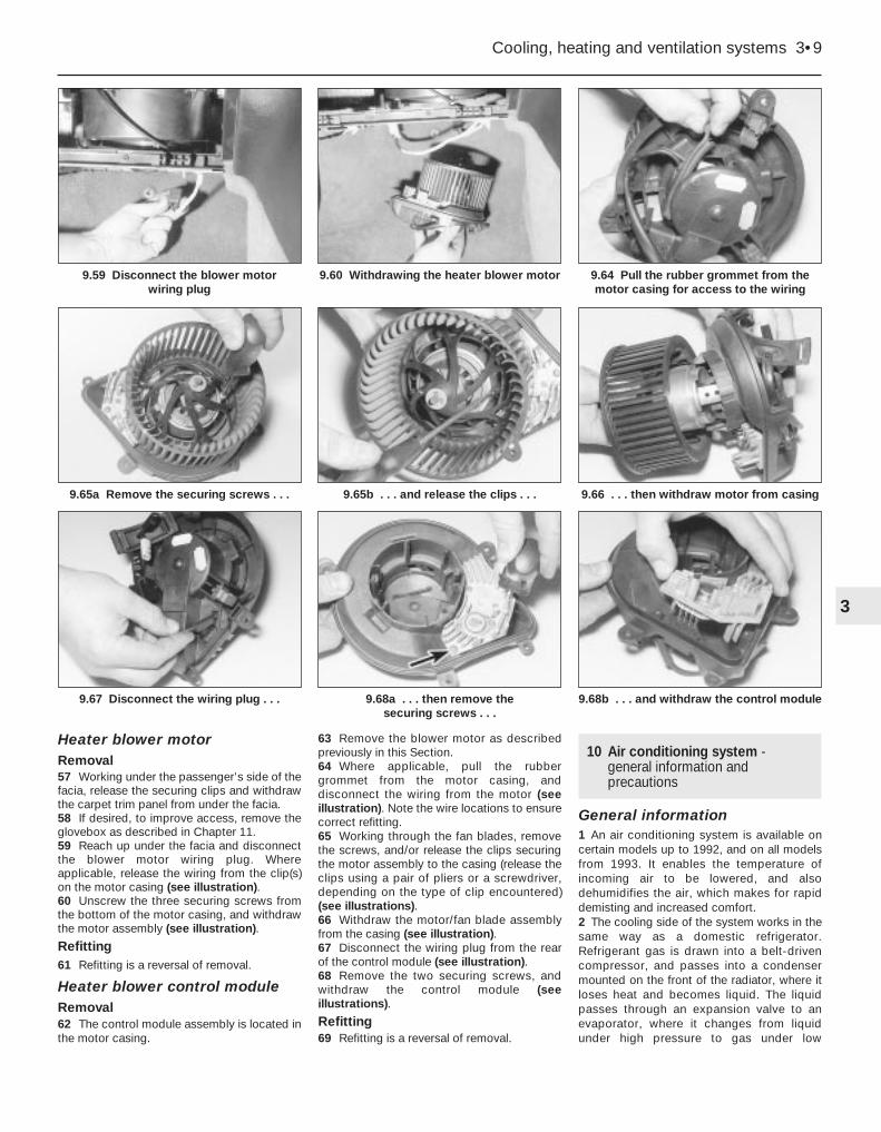
Heater blower motorRemoval57 Working under the passenger’s side of thefacia, release the securing clips and withdrawthe carpet trim panel from under the facia.58 If desired, to improve access, remove theglovebox as described in Chapter 11.59 Reach up under the facia and disconnectthe blower motor wiring plug. Whereapplicable, release the wiring from the clip(s)on the motor casing (see illustration).60 Unscrew the three securing screws fromthe bottom of the motor casing, and withdrawthe motor assembly (see illustration).
Refitting61 Refitting is a reversal of removal.
Heater blower control moduleRemoval62 The control module assembly is located inthe motor casing.
63 Remove the blower motor as describedpreviously in this Section.64 Where applicable, pull the rubbergrommet from the motor casing, anddisconnect the wiring from the motor (seeillustration). Note the wire locations to ensurecorrect refitting.65 Working through the fan blades, removethe screws, and/or release the clips securingthe motor assembly to the casing (release theclips using a pair of pliers or a screwdriver,depending on the type of clip encountered)(see illustrations).66 Withdraw the motor/fan blade assemblyfrom the casing (see illustration).67 Disconnect the wiring plug from the rearof the control module (see illustration).68 Remove the two securing screws, andwithdraw the control module (seeillustrations).
Refitting69 Refitting is a reversal of removal.
10 Air conditioning system -general information andprecautions
General information1 An air conditioning system is available oncertain models up to 1992, and on all modelsfrom 1993. It enables the temperature ofincoming air to be lowered, and alsodehumidifies the air, which makes for rapiddemisting and increased comfort.2 The cooling side of the system works in thesame way as a domestic refrigerator.Refrigerant gas is drawn into a belt-drivencompressor, and passes into a condensermounted on the front of the radiator, where itloses heat and becomes liquid. The liquidpasses through an expansion valve to anevaporator, where it changes from liquidunder high pressure to gas under low
Cooling, heating and ventilation systems 3•9
9.64 Pull the rubber grommet from themotor casing for access to the wiring
9.66 . . . then withdraw motor from casing9.65b . . . and release the clips . . .9.65a Remove the securing screws . . .
9.60 Withdrawing the heater blower motor9.59 Disconnect the blower motor wiring plug
3
9.67 Disconnect the wiring plug . . . 9.68a . . . then remove the securing screws . . .
9.68b . . . and withdraw the control module

pressure. This change is accompanied by adrop in temperature, which cools theevaporator. The refrigerant returns to thecompressor, and the cycle begins again.3 Air blown through the evaporator passes tothe air distribution unit, where it is mixed withhot air blown through the heater matrix toachieve the desired temperature in thepassenger compartment.4 The heating side of the system works in thesame way as on models without airconditioning (see Section 9).5 The operation of the system is controlledelectronically by the “Bitron” control unit,which controls the electric cooling fan(s), thecompressor, and the facia-mounted warninglight. Any problems with the system should bereferred to a Peugeot dealer.
Precautions6 When an air conditioning system is fitted, itis necessary to observe special precautionswhenever dealing with any part of the system,
or its associated components. If for anyreason the system must be disconnected,entrust this task to your Peugeot dealer or arefrigeration engineer.
7 The refrigerant is potentially dangerous,and should only be handled by qualifiedpersons. If it is splashed onto the skin, it cancause frostbite. It is not itself poisonous, butin the presence of a naked flame (including acigarette) it forms a poisonous gas.Uncontrolled discharging of the refrigerant isdangerous, and potentially damaging to theenvironment.8 Do not operate the air conditioning systemif it is known to be short of refrigerant, as thismay damage the compressor.
11 Air conditioning systemcomponents - removal andrefitting
4
The only operation which can be carried outeasily without discharging the refrigerant isrenewal of the compressor drivebelt. This isdescribed in Chapter 1. (The “Bitron”temperature sensor may be renewed usingthe information in Section 6.) All otheroperations must be referred to a Peugeotdealer or an air conditioning specialist.
If necessary, the compressor can beunbolted and moved aside, withoutdisconnecting its flexible hoses, afterremoving the drivebelt.
3•10 Cooling, heating and ventilation systems
Warning: Do not attempt toopen the refrigerant circuit.Refer to the precautions givenin Section 10.
Warning: The refrigerationcircuit may contain a liquidrefrigerant (Freon), and it istherefore dangerous to
disconnect any part of the system withoutspecialised knowledge and equipment.

4A
Fuel pumpType . . . . . . . . . . . . . . . . . . . . . . . . . . . . . . . . . . . . . . . . . . . . . . . . . Mechanical, driven by eccentric on camshaft
CarburettorType . . . . . . . . . . . . . . . . . . . . . . . . . . . . . . . . . . . . . . . . . . . . . . . . . Solex 34-34 Z1, Solex 32-34 Z2 or Weber 36 TLPApplication:
XU engine . . . . . . . . . . . . . . . . . . . . . . . . . . . . . . . . . . . . . . . . . . . . . . Solex 34-34Z1 or Solex 32-34 Z2TU engine . . . . . . . . . . . . . . . . . . . . . . . . . . . . . . . . . . . . . . . . . . . . . . Weber 34 TLP
Choke type . . . . . . . . . . . . . . . . . . . . . . . . . . . . . . . . . . . . . . . . . . . . . . . Manual, cable-operatedSolex carburettor
Float height setting . . . . . . . . . . . . . . . . . . . . . . . . . . . . . . . . . . . . . . . 33.5 mmThrottle valve fast idle setting . . . . . . . . . . . . . . . . . . . . . . . . . . . . . . . 0.5 mmChoke pull-down setting . . . . . . . . . . . . . . . . . . . . . . . . . . . . . . . . . . . 6.0 mm
Weber carburettorFloat height setting . . . . . . . . . . . . . . . . . . . . . . . . . . . . . . . . . . . . . . . 32.0 mmChoke opening after starting . . . . . . . . . . . . . . . . . . . . . . . . . . . . . . . 5.0 mm
Recommended fuelMinimum octane rating:
TU3 (K1G) engine (carburettor) . . . . . . . . . . . . . . . . . . . . . . . . . . . . . . 97 RON leaded or 98 RON (super) unleadedAll other models (both carburettor and fuel injection)without a catalytic converter . . . . . . . . . . . . . . . . . . . . . . . . . . . . . . . 95 RON unleaded* or 97 RON leaded
All other models with a catalytic converter . . . . . . . . . . . . . . . . . . . . . 95 RON unleaded or 98 RON (super) unleaded
*On some early models the ignition timing must be retarded by 3° in order to use 95 RON unleaded fuel - check with your Peugeot dealer.
Torque wrench settings Nm lbf ftFuel pump retaining bolts . . . . . . . . . . . . . . . . . . . . . . . . . . . . . . . . . . . . 16 12Inlet manifold retaining nuts . . . . . . . . . . . . . . . . . . . . . . . . . . . . . . . . . . 8 6Exhaust manifold retaining nuts . . . . . . . . . . . . . . . . . . . . . . . . . . . . . . . 16 12Exhaust system fasteners:
Front pipe-to-manifold nuts . . . . . . . . . . . . . . . . . . . . . . . . . . . . . . . . 30 22Front pipe mounting bolt . . . . . . . . . . . . . . . . . . . . . . . . . . . . . . . . . . 35 26
Chapter 4 Part A:Fuel/exhaust systems - carburettor models
Accelerator cable - removal, refitting and adjustment . . . . . . . . . . . . .7Accelerator pedal - removal and refitting . . . . . . . . . . . . . . . . . . . . . . .8Air cleaner air temperature control system -
general information and component renewal . . . . . . . . . . . . . . . . . .3Air cleaner assembly - removal and refitting . . . . . . . . . . . . . . . . . . . .2Air cleaner filter element renewal . . . . . . . . . . . . . . . . . .See Chapter 1Carburettor - fault diagnosis, overhaul and adjustments . . . . . . . . . .13Carburettor - general information . . . . . . . . . . . . . . . . . . . . . . . . . . . .11Carburettor - removal and refitting . . . . . . . . . . . . . . . . . . . . . . . . . . .12Choke cable - removal, refitting and adjustment . . . . . . . . . . . . . . . . .9Exhaust manifold - removal and refitting . . . . . . . . . . . . . . . . . . . . . .15
Exhaust system check . . . . . . . . . . . . . . . . . . . . . . . . . . .See Chapter 1Exhaust system - general information, removal and refitting . . . . . . .16Fuel filter renewal . . . . . . . . . . . . . . . . . . . . . . . . . . . . . . .See Chapter 1Fuel gauge sender unit - removal and refitting . . . . . . . . . . . . . . . . . . .5Fuel pump - testing, removal and refitting . . . . . . . . . . . . . . . . . . . . . .4Fuel tank - removal and refitting . . . . . . . . . . . . . . . . . . . . . . . . . . . . . .6General information and precautions . . . . . . . . . . . . . . . . . . . . . . . . . .1Idle speed and mixture adjustment . . . . . . . . . . . . . . . . .See Chapter 1Inlet manifold - removal and refitting . . . . . . . . . . . . . . . . . . . . . . . . .14Unleaded petrol - general information and usage . . . . . . . . . . . . . . .10
4A•1
Easy, suitable fornovice with littleexperience
Fairly easy, suitablefor beginner withsome experience
Fairly difficult,suitable for competentDIY mechanic
Difficult, suitable forexperienced DIYmechanic
Very difficult,suitable for expertDIY or professional
Degrees of difficulty
Specifications
Contents

1 General information andprecautions
The fuel system consists of a fuel tankmounted under the rear of the car, amechanical fuel pump, and a carburettor. Thefuel pump is operated by an eccentric on thecamshaft, and is mounted on the rear of thecylinder head. The air cleaner contains adisposable paper filter element, andincorporates a flap valve air temperaturecontrol system; this allows cold air from theoutside of the car, and warm air from theexhaust manifold, to enter the air cleaner inthe correct proportions.
The fuel pump lifts fuel from the fuel tank tothe carburettor via a filter located in the rear ofthe engine compartment, and supplies it to thecarburettor via an anti-percolation chamber.The anti-percolation chamber ensures that thesupply of fuel to the carburettor is kept at aconstant pressure, and is free of air bubbles.Excess fuel is returned from the anti-percolation chamber to the fuel tank.
The carburettor is either a Solex 34-34 Z1 orSolex 32-34 Z2 twin-choke carburettor, orWeber 36TLP single-choke carburettor (seeSection 11), mixture enrichment for cold startingis by automatic choke on the Solex carburettorand a cable-operated choke control on theWeber carburettor. On the Solex carburettor avacuum-operated choke unloader, acceleratorpump and full load enrichener device are fittedto govern the fuel requirements of the engineover its full operating range.
The exhaust system consists of three orfour sections according to model. The frontpipe is in one or two sections; where it is intwo sections the rear section may be plain orinclude a catalytic converter, where it is in onesection it may include a catalytic converter. Allmodels are fitted with an Intermediate pipeand silencer, and a tailpipe and silencer. Thesystem is suspended throughout its entirelength by rubber mountings.
2 Air cleaner assembly -removal and refitting 2
Removal
TU engine1 Slacken the retaining clips (where fitted),and disconnect the vacuum hose andbreather hose from the front of the air cleanerhousing-to-carburettor duct (see illustration).Where the crimped-type Peugeot hose clipsare fitted, cut the clips and discard them; usestandard worm-drive hose clips on refitting.2 Slacken the retaining clips, then lift the ductoff the top of the carburettor and air cleanerhousing. Disconnect the air temperaturecontrol valve hose from the end of the duct,and remove the duct from the enginecompartment (see illustrations). Recover therubber sealing ring(s) from the top of thecarburettor and/or air cleaner housing (asapplicable).3 Disconnect the inlet duct from the front of
the air cleaner housing, and remove the aircleaner housing from the enginecompartment.4 To remove the inlet duct assembly, undothe retaining bolts securing the duct to theleft-hand wing valance, then release thefastener securing the rear of the duct to thecylinder head (see illustration). Disconnectthe hot-air inlet hose from the exhaustmanifold shroud, and remove the duct andhose assembly from the engine compartment.
XU engine5 Using an Allen key, unscrew the boltsecuring the air inlet duct to the top of thecarburettor. Loosen the clip and disconnectthe duct (see illustration).6 Loosen the clip and disconnect the air inletduct from the filter housing top cover.7 Release the clips and remove the top coverfrom the air filter housing.8 Remove the filter element from inside thelower housing.9 Release the lower housing from themounting rubbers then disconnect the inletduct and hoses as applicable.
Refitting10 Refitting is a reversal of the removalprocedure, noting the following points:a) Examine the rubber sealing ring(s) for
signs of damage or deterioration, and ifnecessary renew. Note that, on somemodels, the carburettor seal is fitted withan O-ring; this should also be renewed ifit is damaged.
4A•2 Fuel/exhaust systems - carburettor models
2.1 On the TU engine disconnect thevacuum and breather hoses (arrowed)
from the front of the duct . . .
2.2b . . . and remove the duct,disconnecting the air temperature control
valve hose (arrowed)
2.5 On the XU engine unscrew the boltsecuring the air inlet duct,
then loosen the clip
2.4 Undo the intake duct front bolt thenrelease the rear fastener, and remove the
duct and hose assembly (TU engine)
2.2a . . . slacken the retaining clips . . .Warning: Many of theprocedures in this Chapterrequire the removal of fuel lines
and connections, which may result insome fuel spillage. Before carrying outany operation on the fuel system, refer tothe precautions given in “Safety first!” atthe beginning of this manual, and followthem implicitly. Petrol is a highlydangerous and volatile liquid, and theprecautions necessary when handling itcannot be overstressed.

b) Where applicable, ensure that the aircleaner housing locating peg is correctlyengaged with its mounting on the top ofthe transmission (see illustration).
c) Prior to tightening the air cleaner-to-carburettor duct retaining clips, ensurethat the duct is correctly seated on boththe air cleaner housing and carburettorflanges.
3 Air cleaner air temperaturecontrol system - informationand component renewal
2General information
TU engine1 The system is controlled by a heat-sensitivevacuum switch, mounted in the end of the aircleaner housing-to-carburettor duct. Whenthe engine is started from cold, the switch isopen, allowing inlet manifold depression toact on the air temperature control valvediaphragm in the inlet duct. This vacuumcauses the diaphragm to rise, drawing a flapvalve across the cold-air inlet, thus allowingonly (warmed) air from the exhaust manifold toenter the air cleaner.2 As the temperature of the exhaust-warmedair in the air cleaner-to-carburettor duct rises,the wax capsule in the vacuum switchdeforms and closes the switch, cutting off thevacuum supply to the air temperature controlvalve assembly. As the vacuum supply is cut,the flap is gradually lowered across the hot-air
inlet until, when the engine is fully warmed-upto normal operating temperature, only cold airfrom the front of the car is entering the aircleaner.3 To check the system, allow the engine tocool down completely, then slacken theretaining clip and disconnect the inlet ductfrom the front of the control valve assembly;the flap valve in the duct should be securelyseated across the hot-air inlet. Start theengine; the flap should immediately rise toclose off the cold-air inlet, and should thenlower steadily as the engine warms up, until itis eventually seated across the hot-air inletagain.4 To check the vacuum switch, disconnectthe vacuum pipe from the control valve whenthe engine is running, and place a finger overthe pipe end. When the engine is cold, fullinlet manifold vacuum should be present inthe pipe, and when the engine is at normaloperating temperature, there should be novacuum in the pipe.5 To check the air temperature control valveassembly, slacken the retaining clip anddisconnect the inlet duct from the front of thevalve assembly; the flap valve should besecurely seated across the hot-air inlet.Disconnect the vacuum pipe, and suck hardat the control valve stub; the flap should riseto shut off the cold-air inlet.6 If either component is faulty, it must berenewed.
XU engine7 Cold air is drawn into the system from theinlet duct fitted to the front panel.
8 Hot air is drawn from the collector plateover the exhaust manifold. These two ductsjoin together at the air inlet mixer housingwhich contains a control flap operated by awax thermostat (see illustrations).9 When the engine is cold the thermostatcontracts and the control flap closes off thecold air duct and opens the hot air duct. Asthe air being collected from the exhaustmanifold becomes warmer, so the thermostatprogressively closes off the warm air duct andopens the cold air duct.10 If the thermostat should fail, renew themixer housing.11 All the ducts are held by worm drive clips.12 Additional breather pipes are connectedto the air filter housing on certain models.
Vacuum switch (TU engine) - renewal13 Remove the air cleaner housing-to-carburettor duct, as described in para-graphs 1 and 2 of Section 2.14 Bend up the tangs on the switch retainingclip, then remove the clip, along with its seal,and withdraw the switch from inside the duct(see illustrations). Examine the seal for damageor deterioration, and renew if necessary.15 On refitting, ensure that the switch andduct mating surfaces are clean and dry, andposition the switch inside the duct.16 Fit the seal over the switch unions, andrefit the retaining clip. Ensure that the switchis pressed firmly against the duct, and secureit in position by bending down the retainingclip tangs. Refit the duct as described inSection 2.
Fuel/exhaust systems - carburettor models 4A•3
3.8b Wax thermostat on the air inlet mixerhousing (XU engine)
3.14c . . . then withdraw the vacuumswitch from inside the duct
3.14b . . . and seal . . .3.14a Remove the retaining clip . . .
3.8a Hot-air collector plate on exhaustmanifold (XU engine)
4A
2.10 Air cleaner housing peg andmounting rubber (arrowed)

Air temperature control valve(TU engine) - renewal17 Disconnect the vacuum pipe from the airtemperature control valve, then slacken theretaining clips securing the inlet ducts to thevalve (see illustration).18 Disconnect both inlet ducts and the hot-air inlet hose from the control valve assembly,and remove it from the vehicle.19 Refitting is the reverse of the removalprocedure, noting that the air temperaturecontrol valve assembly can only be renewedas a complete unit.
4 Fuel pump - testing, removal and refitting 2
Note: Refer to the warning note in Section 1before proceeding.
Testing1 To test the fuel pump on the engine,disconnect the outlet pipe which leads to thecarburettor. Hold a wad of rag by the pumpoutlet while an assistant spins the engine onthe starter. Keep your hands away from theelectric cooling fan. Regular spurts of fuelshould be ejected as the engine turns. Becareful not to spill fuel onto hot enginecomponents.2 The pump can also be tested by removingit. With the pump outlet pipe disconnectedbut the inlet pipe still connected, hold the wadof rag by the outlet. Operate the pump leverby hand, moving it in and out; if the pump is ina satisfactory condition, the lever shouldmove and return smoothly, and a strong jet offuel should be ejected.
Removal3 Identify the pump inlet and outlet hoses,and slacken both retaining clips (seeillustration). Where the crimped-typePeugeot hose clips are fitted, cut the clips anddiscard them; use standard worm-drive hoseclips on refitting. Place wads of rag beneaththe hose unions to catch any spilled fuel, thendisconnect both hoses from the pump; plugthe hose ends to minimise fuel loss.
TU engine4 Where fitted remove the insulating coverfrom the fuel pump, then slacken and removethe bolts securing the pump to the rear of thecylinder head. Remove the pump along withits insulating block. Check the block andrenew it if necessary.
XU engine5 Unscrew the nuts securing the pump to thedistributor end of the cylinder head and lift offthe pump (see illustration).6 Remove the insulating block from the studson the cylinder head.
Refitting7 Ensure that the pump and cylinder headmating surfaces are clean and dry, then offerup the insulating block and refit the pump tothe cylinder head. Tighten the pump retainingbolts/nuts to the specified torque, then refitthe pump insulating cover where fitted8 Reconnect the inlet and outlet hoses to therelevant pump unions, and securely tightentheir retaining clips.
5 Fuel gauge sender unit -removal and refitting 3
Note: Refer to the warning note in Section 1before proceeding.
Removal1 Disconnect the battery negative lead.
2 For access to the sender unit, fold the rearseat cushion forwards or remove the rearseats as described in Chapter 11.3 Using a screwdriver, carefully prise theplastic access cover from the floor to exposethe sender unit (see illustration).4 Disconnect the wiring connector from thesender unit (see illustration).
5 Mark the hoses for identification purposes,then slacken the feed and return hose clips.Where the crimped-type Peugeot hose clipsare fitted, cut the clips and discard them; usestandard worm-drive hose clips on refitting.Disconnect both hoses from the top of thesender unit, and plug the hose ends.6 Noting the alignment marks on the tank,sender unit and the locking ring, unscrew thering and remove it from the tank. This is bestachieved by using a screwdriver on the raisedribs of the locking ring, as follows. Carefullytap the screwdriver to turn the ring anti-clockwise until it can be unscrewed by hand.7 Carefully lift the sender unit from the top ofthe fuel tank, taking great care not to bend thesender unit float arm, or to spill fuel onto theinterior of the vehicle. Recover the rubbersealing ring and discard it - a new one mustbe used on refitting. If necessary remove thefilter from the bottom of the unit and wash it inclean fuel.
4A•4 Fuel/exhaust systems - carburettor models
3.17 Air temperature control valveassembly (TU engine)
4.5 Removing the fuel pump (XU engine)
5.4 Electrical plug (A) and fuel hoseconnections (B) on fuel gauge sender
5.3 Remove the plastic access cover . . .
4.3 Arrows on raised fuel pump unionsindicate the direction of fuel flow
Tape the connector to thevehicle body, in order toprevent it from disappearingbehind the tank .

Refitting8 Refitting is a reversal of the removalprocedure, noting the following points:a) Prior to refitting, fit a new rubber sealing
ring to the sender unit.b) Refit the sender unit to the tank, aligning
its arrow with the centre of the threealignment marks on the fuel tank. Securethe sender in position with the lockingring, and check that the locking ring,sender unit and fuel tank marks are allcorrectly aligned.
c) Ensure that the feed and return hoses arecorrectly reconnected and securelyretained by their clips.
6 Fuel tank - removal and refitting 3
Note: Refer to the warning note in Section 1before proceeding.
Removal1 Before removing the fuel tank, all fuel mustbe drained from the tank. Since a fuel tankdrain plug is not provided, it is preferable tocarry out the removal operation when the tankis nearly empty. Before proceeding,disconnect the battery negative lead andsyphon or hand-pump the remaining fuel fromthe tank.2 Remove the exhaust system and relevantheat shield(s) as described in Section 16.3 From underneath the vehicle, disconnectthe handbrake cable at the equaliser bracket.4 Release the handbrake primary cable fromthe clips in the fuel tank. Position the cableclear of the tank, so that it will not hinder theremoval procedure.5 Disconnect the wiring connector from thefuel gauge sender unit, as described inSection 5.6 Working at the right-hand side of the fueltank, release the retaining clips thendisconnect the filler neck vent pipe and mainfiller neck hose from the fuel tank/filler neck.Where necessary, also disconnect thebreather hose(s). Some breather hoses arejoined to the tank with quick-release fittings; todisconnect these fittings, slide the cover along
the hose then depress the centre ring and pullthe hose out of its fitting (see illustration).7 Trace the fuel feed and return hoses backfrom the right-hand side of the tank to theirunion with the fuel pipes. Slacken theretaining clips and disconnect both hosesfrom the fuel pipes. Where the crimped-typePeugeot hose clips are fitted, cut the clips anddiscard them; use standard worm-drive hoseclips on refitting. Plug the hose and pipe ends,to prevent the entry of dirt into the system.8 Place a trolley jack with an interposed blockof wood beneath the tank, then raise the jackuntil it is supporting the weight of the tank.9 Slacken and remove the retaining nut andbolts, then remove the two support rods fromthe underside of the tank (see illustration).10 Slowly lower the fuel tank out of position,disconnecting any other relevant vent pipes asthey become accessible (where necessary),and remove the tank from underneath the car.11 If the tank is contaminated with sedimentor water, remove the sender unit (Section 5),and swill the tank out with clean fuel. The tankis injection-moulded from a synthetic material- if seriously damaged, it should be renewed.However, in certain cases, it may be possibleto have small leaks or minor damage repaired.Seek the advice of a specialist beforeattempting to repair the fuel tank.
Refitting12 Refitting is the reverse of the removalprocedure, noting the following points:
a) When lifting the tank back into position,take care to ensure that none of the hoses
become trapped between the tank andvehicle body.
b) Ensure that all pipes and hoses arecorrectly routed, and securely held inposition with their retaining clips.
c) Reconnect the handbrake cables andadjust the handbrake (see Chapter 9).
d) On completion, refill the tank with a smallamount of fuel, and check for signs ofleakage prior to taking the vehicle out onthe road.
7 Accelerator cable - removal,refitting and adjustment 2
Removal1 Working in the engine compartment, freethe accelerator inner cable from thecarburettor throttle cam, then pull the outercable out from its mounting bracket rubbergrommet (see illustrations). Where fitted,slide the flat washer off the end of the cable,and remove the spring clip.2 Working back along the length of the cable,free it from any retaining clips or ties, notingits correct routing.3 Where necessary remove the lower trimfrom below the driver’s side of the facia panel.4 Working from inside the vehicle, disconnectthe cable from the accelerator pedal bydepressing the lugs on the plastic end fittingand pushing the fitting from the pedal (seeillustration).
Fuel/exhaust systems - carburettor models 4A•5
7.1a Accelerator cable connection on thethrottle quadrant (arrowed)
8 Cover 9 Centre ring 10 Hose
7.4 Accelerator cable connection toaccelerator pedal (arrowed)
7.1b Outer cable end fitting
6.9 Fuel tank support strap bolt
4A
6.6 Tank breather quick-release connector

5 Release the outer cable from its retainer onthe pedal mounting bracket, then tie a lengthof string to the end of the cable.6 Return to the engine compartment, releasethe cable grommet from the bulkhead andwithdraw the cable. When the end of thecable appears, untie the string and leave it inposition - it can then be used to draw thecable back into position on refitting.
Refitting7 Tie the string to the end of the cable, thenuse the string to draw the cable into positionthrough the bulkhead. Once the cable end isvisible, untie the string, then clip the outercable into its pedal bracket retainer, and clipthe inner cable into position in the pedal end.The remaining procedure is a reversal ofremoval, but adjust it as follows.
Adjustment8 Remove the spring clip from the acceleratorouter cable. Ensuring that the throttle cam isfully against its stop, gently pull the cable outof its grommet until all free play is removedfrom the inner cable.9 With the cable held in this position, refit thespring clip to the last exposed outer cablegroove in front of the rubber grommet andwasher. When the clip is refitted and the outercable is released, there should be only a smallamount of free play in the inner cable (seeillustration).10 Have an assistant depress the acceleratorpedal, and check that the throttle cam opensfully and returns smoothly to its stop.11 For models fitted with automatictransmission refer to Chapter 7, Part B.
8 Accelerator pedal - removal and refitting 2
Removal1 Disconnect the accelerator cable from thepedal as described in Section 7.2 Remove the screws from the pedal pivotbush and lift out the pedal (see illustration).3 Examine the pivot bush and shaft for signsof wear, and renew as necessary.
Refitting4 Refitting is a reversal of the removalprocedure, applying a little multi-purposegrease to the pedal pivot point. Oncompletion, adjust the accelerator cable asdescribed in Section 7.
9 Choke cable - removal,refitting and adjustment 2
Removal1 Release the choke inner cable from thecarburettor linkage.2 Slacken and remove the retaining bolt andremove the outer cable retaining clamp.3 Slacken the retaining clip securing therubber collar to the outer cable, and slide thecollar off the cable. Where the originalcrimped-type Peugeot hose clip is still fitted,cut the clip and discard it; use a standardworm-drive hose clip on refitting.4 Working back along the length of the cable,free it from any retaining clips or ties, notingits correct routing. Tie a length of string to theend of the choke inner cable.5 Working from inside the vehicle, pull thechoke lever fully out, to gain access to theretaining screw. Unclip the choke lever fromthe facia and withdraw the lever and cableassembly from the facia, disconnecting thewiring from the lever switch (where fitted) as itbecomes accessible. Once the end of thecable appears through the lever aperture,untie the string and leave it in position in thevehicle - it can then be used to draw the cableback into position on refitting.
Refitting6 Tie the string to the end of the choke cable,then use the string to draw the cable intoposition through the bulkhead into the enginecompartment. Once the cable end is fully inposition, untie the string.7 Reconnect the wiring connector (wherefitted), and clip the choke lever in its faciapanel aperture.8 From within the engine compartment,ensure that the outer cable is correctly seatedin the bulkhead grommet. Work along the
cable, securing it in position with all therelevant retaining clips and ties, and ensuringthat the cable is correctly routed.9 Slide the rubber collar and retaining cliponto the end of the cable, then engage theinner end of the cable with carburettorlinkage. Align the rubber collar with thecarburettor bracket, then refit the retainingclip and securely tighten its retaining bolt.Adjust the cable as described below.
Adjustment10 Slacken the clip securing the rubber collarto the outer cable. Where the crimped-typePeugeot hose clip is still fitted, cut the clipand discard it; use a standard worm-drivehose clip on refitting (see illustration).11 Ensuring that the choke lever is flush withthe facia panel and the carburettor linkage isfully against its stop, move the outer cable inthe rubber collar until the position is foundwhere there is only a small amount of free playpresent in the inner cable. Hold the outercable in this position, and securely tighten theclip securing the rubber collar to the outercable.12 Have an assistant operate the chokelever, and check that the choke linkage closesfully and returns smoothly to its stop. Ifnecessary, repeat the adjustment procedure.
10 Unleaded petrol - generalinformation and usage
Note: The information given in this Chapter iscorrect at the time of writing. If updatedinformation is required, check with a Peugeotdealer. If travelling abroad, consult one of themotoring organisations (or a similar authority)for advice on the fuel available.
The fuel recommended by Peugeot is givenin the Specifications Section of this Chapter,followed by the equivalent petrol currently onsale in the UK.
All Peugeot 405 carburettor models aredesigned to run on 95 octane petrol. Bothleaded and unleaded petrol can be usedwithout modification. Super leaded (97 octane, UK “4-star”) and super unleaded(98 octane) petrol can also be used if wished,though there is no advantage in doing so.
9.10 Choke cable-to-rubber collarretaining clip (arrowed)
4A•6 Fuel/exhaust systems - carburettor models
7.9 Adjusting the accelerator cable 8.2 Accelerator pedal pivot bush

11 Carburettor - general information
The Solex 34-34 Z1 carburettor is adowndraught progressive twin-venturiinstrument. The throttle linkages are arrangedso that the secondary throttle valve will notstart to open until the primary valve is abouttwo-thirds open, but at full throttle both valvesare fully open. The choke control is eitherautomatic or manual. On some early models acarburettor cooling system was fitted whichallows the radiator cooling fan to run for amaximum of 12 minutes after the engine hasbeen switched off.
The Weber 34TLP carburettor is a singlechoke downdraught type instrument fittedwith a manual choke.
12 Carburettor - removal and refitting 3
Note: Refer to the warning note in Section 1before proceeding. Where original crimped-type Peugeot hose clips are still fitted, theclips should be cut and discarded; obtainsome worm-drive hose clips for refitting.
Removal1 Disconnect the battery negative terminal.2 Remove the air cleaner-to-carburettor ductas described in Section 2.3 Disconnect the accelerator cable from thethrottle quadrant as described in Section 8.4 Disconnect the distributor vacuum pipe(see illustration).5 Disconnect the float chamber breather
pipes. The upper pipe connects with the airfilter housing (see illustration).6 Either drain the cooling system or clampthe automatic choke and carburettor baseheating pipes, then disconnect the pipes (seeillustrations).7 Disconnect the float chamber solenoidvalve wiring (see illustration).8 Disconnect the fuel inlet pipe either at thefuel pump or the fuel reservoir on the side ofthe carburettor and blank off the hose.9 Remove the single carburettor securing nutand lift off the fuel reservoir (see illustration).10 Remove the remaining carburettor nutsand lift off the carburettor (see illustrations).11 Remove the insulating spacer and/orgasket(s) (see illustration). Discard thegasket(s); new ones must be used on refitting.Plug the inlet manifold port with a wad ofclean cloth, to prevent the entry of debris.
Fuel/exhaust systems - carburettor models 4A•7
12.6a Automatic choke coolant pipeconnection . . .
12.9 Lifting off the fuel reservoir12.7 Disconnecting the float chamberbreather solenoid wiring
12.6b . . . and base heating pipes
12.5 Disconnecting the float chamberbreather pipe
4A
12.4 Disconnecting the distributor vacuum pipe
12.10a Remove the remaining nuts . . . 12.10b . . . and lift off the carburettor 12.11 Removing the insulating spacer

Refitting12 Refitting is the reverse of the removalprocedure, noting the following points:
a) Ensure that the carburettor and inletmanifold sealing faces are clean and flat.Fit a new gasket, and securely tighten thecarburettor retaining nuts.
b) Use the notes made on dismantling toensure that all hoses are refitted to theiroriginal positions and, where necessary,are securely held by their retaining clips.
c) Where the original crimped-type Peugeothose clips were fitted, discard them; usestandard worm-drive hose clips whenrefitting.
d) Refit and adjust the choke andaccelerator cables as described inSections 7 and 9.
e) Refit the air cleaner duct as described inSection 2.
f) On completion, check and, if necessary,adjust the idle speed and mixture settingsas described in Chapter 1.
13 Carburettor - fault diagnosis,overhaul and adjustments 2
Fault diagnosis1 If a carburettor fault is suspected, alwayscheck first that the ignition timing is correctlyset, that the spark plugs are in good conditionand correctly gapped, that the acceleratorand choke cables are correctly adjusted, andthat the air cleaner filter element is clean; referto the relevant Sections of Chapter 1, Chapter5 or this Chapter. If the engine is running veryroughly, first check the valve clearances asdescribed in Chapter 1, then check thecompression pressures as described inChapter 2.2 If careful checking of all the aboveproduces no improvement, the carburettormust be removed for cleaning and overhaul.3 Prior to overhaul, check the availability ofcomponent parts before starting work; notethat most sealing washers, screws andgaskets are available in kits, as are some ofthe major sub-assemblies. In most cases, itwill be sufficient to dismantle the carburettorand to clean the jets and passages.
OverhaulNote: Refer to the warning note in Section 1before proceeding. Only carry out theprocedures described in this Section, asspecial gauges are required for a moredetailed overhaul. The following procedureapplies to the Solex 34-34 Z1 carburettor.4 Remove the carburettor from the vehicle asdescribed in Section 12.5 Unscrew the idle cut-off solenoid from thecarburettor body, and remove it along with itsplunger and spring. To test the solenoid,connect a 12-volt battery to it (positive
terminal to the solenoid terminal, negativeterminal to the solenoid body), and check thatthe plunger is retracted fully into the body.Disconnect the battery, and check that theplunger is pushed out by spring pressure. Ifthe valve does not perform as expected, andcleaning does not improve the situation, thesolenoid valve must be renewed.6 Remove the five screws and lift off thecarburettor upper body.7 Tap out the float pivot pin and remove thefloat assembly, needle valve, and floatchamber gasket. Check that the needle valveanti-vibration ball is free in the valve end, thenexamine the needle valve tip and seat for wearor damage. Examine the float assembly andpivot pin for signs of wear and damage. Thefloat assembly must be renewed if it appearsto be leaking - shake the float to detect thepresence of fuel inside.8 Unscrew the fuel inlet union and inspect thefuel filter. Clean the filter housing of debrisand dirt, and renew the filter if it is blocked.9 Undo the four screws, detach theaccelerator pump cover, and remove thepump diaphragm and spring, noting whichway around they are fitted. Examine thediaphragm for signs of damage anddeterioration, and renew if necessary.Remove the choke pull-down diaphragm andpart-load enrichment diaphragms, andexamine them in the same way.10 Unscrew the idle jet from the upper body.11 Unscrew both the primary and secondarycombined air correction jets and emulsiontubes.12 Using a long thin screwdriver, unscrewthe main jets from the bottom of the emulsiontube drillings. Invert the carburettor and catchthe jets as they fall out of the drillings.13 Remove the idle mixture adjustmentscrew tamperproof cap. Screw the screw inuntil it seats lightly, counting the exactnumber of turns required to do this, thenunscrew it. On refitting, screw the screw inuntil it seats lightly, then back the screw off bythe number of turns noted on removal, toreturn the screw to its original position.14 Clean the jets, carburettor bodyassemblies, float chamber and internaldrillings. An air line may be used to clear theinternal passages once the carburettor is fullydismantled. Caution: If high pressure air isdirected into drillings and passages wherea diaphragm is fitted, the diaphragm islikely to be damaged.
15 Use a straight edge to check allcarburettor body assembly mating surfacesfor distortion.16 To test the carburettor heating element,connect a multimeter, set to the resistance
function, between the heater wiring terminaland the carburettor body. A resistancereading of approximately 0.25 to 0.5 ohmsshould be obtained. If an open-circuit ispresent, or an extremely high resistancereading is obtained, it is likely that the heatingelement is faulty. A heating element repair kitis available from your Peugeot dealer. Torenew the element undo the screw andremove the retaining plate, then slide theelement holder, pin, element and insulatingplate, noting each component correct fittedlocation. Fit the new components, ensuringeach one is correctly positioned, and securelytighten the retaining screws. Note: Ensurethat the insulating plate is correctly positionedbetween the heating element and body so thatthere is no danger of the element shorting outon the carburettor body.17 On reassembly renew any worncomponents and fit a complete set of newgaskets and seals. A jet kit and a gasket andseal kit are available from your Peugeotdealer.18 Reassembly is a reversal of thedismantling procedure. Ensure that all jets aresecurely locked in position, but take greatcare not to overtighten them. Ensure that allmating surfaces are clean and dry, and that allbody sections are correctly assembled withtheir fuel and air passages correctly aligned.Prior to refitting the carburettor to the vehicle,set the float height, throttle valve fast idle andchoke pull-down settings as described below.
Adjustments
Idle speed and mixture19 Refer to Chapter 1.
Float height setting (Solex carburettor)20 Invert the carburettor body, so that thefloat is at the top and the needle valve isdepressed. Measure the distance betweenthe upper edge of the float and the sealingface of the upper body (with its gasket fitted).This measurement should be as given in theSpecifications at the start of this Chapter.21 If necessary, the float height can beadjusted by carefully bending the small tangon the float arm which contacts the needlevalve.
Throttle valve fast idle setting (Solex carburettor)22 Invert the carburettor and pull thecarburettor choke linkage to fully close thechoke valve. The fast idle screw will buttagainst the fast idle cam and force the throttlevalve open slightly.23 Using the shank of a twist drill, measurethe clearance between the edge of the throttlevalve and bore, and compare this to theclearance given in the Specifications at thestart of this Chapter. If necessary, adjust byturning the fast idle adjustment screw in theappropriate direction until the specifiedclearance is obtained (see illustration).
4A•8 Fuel/exhaust systems - carburettor models
Aerosol cans of carburettorcleaner are widely availableand can prove very useful inhelping to clear internal
passages of stubborn obstructions.

Choke pull-down setting (Solex carburettor)24 Pull the carburettor choke linkage to fullyclose the choke valve, and hold the linkage inthis position.25 Attach a hand-held vacuum pump to thechoke pull-down diaphragm, and apply avacuum to the diaphragm so that thediaphragm rod is pulled fully into thediaphragm body. In the absence of a vacuumpump, the rod can be pushed into thediaphragm with a small screwdriver.26 With the rod fully retracted, use the shankof a twist drill to measure the clearancebetween the edge of the choke valve andbore, and compare this to the clearance givenin the Specifications (see illustration). Ifnecessary, remove the plug from thediaphragm cover and adjust by turning theadjustment screw. Once the pull-down settingis correctly adjusted, refit the plug to thediaphragm cover and remove the vacuumpump (where used).
Float height setting (Weber carburettor)27 For float and level settings, remove thefloat chamber cover and hold it vertically.
28 With the gasket in position, use a steelrule or vernier calipers to check the height ofthe floats. Bend the float tongue andconnecting bars if necessary.
Choke opening after starting (Weber carburettor)29 Remove the air inlet from the top of thecarburettor. Pull the choke control knob outfully to close the choke flap.30 Disconnect the vacuum pipe from theanti-flood capsule.31 Connect a hand vacuum pump (or amodified bicycle pump) to the capsule. Applyvacuum (400 mm Hg approx.) to the capsule.The choke flap should open far enough toadmit a drill shank or rod 5 mm in diameter.32 Adjust if necessary by means of the screwon the anti-flood capsule.33 Disconnect the vacuum pump, remakethe original vacuum connection, and close thechoke flap.34 Having adjusted the anti-flood capsule,move the choke opening roller into the recessof the cam as shown (see illustration).35 Check that the choke flap opening justadmits a drill shank or rod 8 mm in diameter.36 Adjust by turning the nut shown (seeillustration) after removing the carburettor.
14 Inlet manifold - removal and refitting 3
Note: Refer to the warning note in Section 1before proceeding.
Removal1 Remove the carburettor as described inSection 12.2 On TU engines, drain the cooling system asdescribed in Chapter 1, and disconnect thecoolant hose from the base of the manifold.3 Disconnect the brake vacuum servo hose atthe manifold.4 Disconnect the oil filler cap breather hosefrom the manifold.5 Unbolt the oil filler tube bracket.6 Unscrew the retaining nuts, thenmanoeuvre the manifold away from the headand out of the engine compartment. Note thaton the TU engine there is no manifold gasket.A gasket is however fitted on XU engines. OnXU engines note the centre clamp secured byone nut (see illustration).
Refitting7 Refitting is the reverse of the removalprocedure, noting the following points:
a) Ensure that the manifold and cylinderhead mating surfaces are clean and dry.Fit a new gasket on XU engines, andapply a thin coating of suitable sealingcompound to the manifold mating surfaceon TU engines. Install the manifold andtighten its retaining nuts to the specifiedtorque setting.
b) Ensure that all relevant hoses arereconnected to their original positions andare securely held (where necessary) bytheir retaining clips.
c) Refit the carburettor as described inSection 12.
d) Where applicable, refill the cooling systemas described in Chapter 1.
Fuel/exhaust systems - carburettor models 4A•9
14.6 Inlet manifold centre clamp on the XU engine
13.36 Choke mechanical openingadjustment nut (4) (Weber carburettor)
4A
13.23 Throttle valve fast idle setting (Solex carburettor)
13.34 Checking the choke mechanicalopening (Weber carburettor)
Adjust until clearance X is as specifiedAdjust screw Y until clearance X is as given inthe Specifications
a Cam 3 Roller
13.26 Choke pull-down setting (using ascrewdriver to retract the diaphragm rod)
(Solex carburettor)
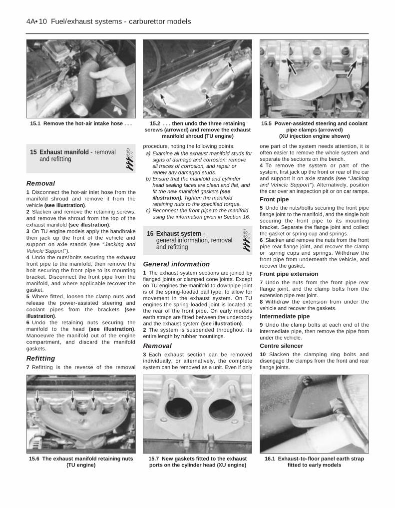
15 Exhaust manifold - removaland refitting 3
Removal1 Disconnect the hot-air inlet hose from themanifold shroud and remove it from thevehicle (see illustration).2 Slacken and remove the retaining screws,and remove the shroud from the top of theexhaust manifold (see illustration).3 On TU engine models apply the handbrakethen jack up the front of the vehicle andsupport on axle stands (see “Jacking andVehicle Support”).4 Undo the nuts/bolts securing the exhaustfront pipe to the manifold, then remove thebolt securing the front pipe to its mountingbracket. Disconnect the front pipe from themanifold, and where applicable recover thegasket.5 Where fitted, loosen the clamp nuts andrelease the power-assisted steering andcoolant pipes from the brackets (seeillustration).6 Undo the retaining nuts securing themanifold to the head (see illustration).Manoeuvre the manifold out of the enginecompartment, and discard the manifoldgaskets.
Refitting7 Refitting is the reverse of the removal
procedure, noting the following points:a) Examine all the exhaust manifold studs for
signs of damage and corrosion; removeall traces of corrosion, and repair orrenew any damaged studs.
b) Ensure that the manifold and cylinderhead sealing faces are clean and flat, andfit the new manifold gaskets (seeillustration). Tighten the manifoldretaining nuts to the specified torque.
c) Reconnect the front pipe to the manifoldusing the information given in Section 16.
16 Exhaust system - general information, removaland refitting
3General information1 The exhaust system sections are joined byflanged joints or clamped cone joints. Excepton TU engines the manifold to downpipe jointis of the spring-loaded ball type, to allow formovement in the exhaust system. On TUengines the spring-loaded joint is located atthe rear of the front pipe. On early modelsearth straps are fitted between the underbodyand the exhaust system (see illustration).2 The system is suspended throughout itsentire length by rubber mountings.
Removal3 Each exhaust section can be removedindividually, or alternatively, the completesystem can be removed as a unit. Even if only
one part of the system needs attention, it isoften easier to remove the whole system andseparate the sections on the bench.4 To remove the system or part of thesystem, first jack up the front or rear of the carand support it on axle stands (see “Jackingand Vehicle Support”). Alternatively, positionthe car over an inspection pit or on car ramps.
Front pipe5 Undo the nuts/bolts securing the front pipeflange joint to the manifold, and the single boltsecuring the front pipe to its mountingbracket. Separate the flange joint and collectthe gasket or spring cup and springs.6 Slacken and remove the nuts from the frontpipe rear flange joint, and recover the clampor spring cups and springs. Withdraw thefront pipe from underneath the vehicle, andrecover the gasket.
Front pipe extension7 Undo the nuts from the front pipe rearflange joint, and the clamp bolts from theextension pipe rear joint.8 Withdraw the extension from under thevehicle and recover the gaskets.
Intermediate pipe9 Undo the clamp bolts at each end of theintermediate pipe, then remove the pipe fromunder the vehicle.
Centre silencer10 Slacken the clamping ring bolts anddisengage the clamps from the front and rearflange joints.
4A•10 Fuel/exhaust systems - carburettor models
15.1 Remove the hot-air intake hose . . . 15.5 Power-assisted steering and coolantpipe clamps (arrowed)
(XU injection engine shown)
16.1 Exhaust-to-floor panel earth strapfitted to early models
15.7 New gaskets fitted to the exhaustports on the cylinder head (XU engine)
15.6 The exhaust manifold retaining nuts(TU engine)
15.2 . . . then undo the three retainingscrews (arrowed) and remove the exhaust
manifold shroud (TU engine)

11 Unhook the centre silencer from itsmounting rubber and remove it fromunderneath the vehicle.
Tailpipe and silencer12 Slacken the tailpipe clamping ring boltsand disengage the clamp from the flangejoint.13 Unhook the tailpipe from its mountingrubbers and remove it from the vehicle.
Complete system14 Undo the nuts securing the front pipeflange joint to the manifold, and the single boltsecuring the front pipe to its mountingbracket. Separate the flange joint and collectthe gasket. Free the system from all itsmounting rubbers and lower it from under thevehicle.
Heat shield(s)15 The heat shields are secured to theunderside of the body (and on some modelsto the fuel tank) by various nuts and bolts (see illustration). Each shield can beremoved once the relevant exhaust sectionhas been removed. If a shield is being
removed to gain access to a componentlocated behind it, it may prove sufficient insome cases to remove the retaining nutsand/or bolts, and simply lower the shield,without disturbing the exhaust system.
Refitting16 Each section is refitted by reversing theremoval sequence, noting the following:a) Ensure that all traces of corrosion have
been removed from the flanges andrenew all necessary gaskets.
b) Inspect the rubber mountings for signs ofdamage or deterioration, and renew asnecessary.
c) Prior to assembling the spring-loadedjoint, a smear of high-temperature greaseshould be applied to the joint matingsurfaces.
d) Where joints are secured together by aclamping ring, apply a smear of exhaustsystem jointing paste to the flange joint,to ensure a gas-tight seal. Tighten theclamping ring nuts evenly andprogressively to the specified torquesetting, so that the clearance between theclamp halves remains equal on eitherside.
e) Prior to tightening the exhaust systemfasteners, ensure that all rubbermountings are correctly located, and thatthere is adequate clearance between theexhaust system and vehicle underbody.Move the system side-to-side, and up-and-down, to ensure it will not hitanything when the car is moving.
Fuel/exhaust systems - carburettor models 4A•11
16.15 Heat shield on the underside of the fuel tank
4A
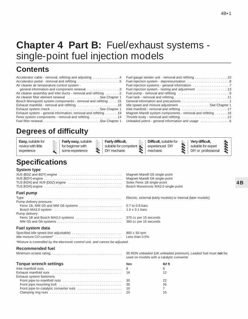
4B
System typeXU5 (BDZ and BDY) engine . . . . . . . . . . . . . . . . . . . . . . . . . . . . . . . . . . Magneti Marelli G5 single-pointXU5 (BDY) engine . . . . . . . . . . . . . . . . . . . . . . . . . . . . . . . . . . . . . . . . . . Magneti Marelli G6 single-pointTU3 (KDX) and XU9 (DDZ) engine . . . . . . . . . . . . . . . . . . . . . . . . . . . . . Solex Fenix 1B single-pointTU3 (KDX) engine . . . . . . . . . . . . . . . . . . . . . . . . . . . . . . . . . . . . . . . . . . Bosch Monotronic MA3.0 single-point
Fuel pumpType . . . . . . . . . . . . . . . . . . . . . . . . . . . . . . . . . . . . . . . . . . . . . . . . . Electric, external (early models) or internal (later models)Pump delivery pressure:
Fenix 1B, MM G5 and MM G6 systems . . . . . . . . . . . . . . . . . . . . . . . 0.7 to 0.8 barsBosch MA3.0 system . . . . . . . . . . . . . . . . . . . . . . . . . . . . . . . . . . . . . 1.0 ± 0.1 bars
Pump delivery:Fenix 1B and Bosch MA3.0 systems . . . . . . . . . . . . . . . . . . . . . . . . . 370 cc per 15 secondsMM G5 and G6 systems . . . . . . . . . . . . . . . . . . . . . . . . . . . . . . . . . . . 360 cc per 15 seconds
Fuel system dataSpecified idle speed (not adjustable) . . . . . . . . . . . . . . . . . . . . . . . . . . . 850 ± 50 rpmIdle mixture CO content* . . . . . . . . . . . . . . . . . . . . . . . . . . . . . . . . . . . . Less than 0.5%
*Mixture is controlled by the electronic control unit, and cannot be adjusted.
Recommended fuelMinimum octane rating . . . . . . . . . . . . . . . . . . . . . . . . . . . . . . . . . . . . . . 95 RON unleaded (UK unleaded premium). Leaded fuel must not be
used on models with a catalytic converter
Torque wrench settings Nm lbf ftInlet manifold nuts . . . . . . . . . . . . . . . . . . . . . . . . . . . . . . . . . . . . . . . . . 8 6Exhaust manifold nuts . . . . . . . . . . . . . . . . . . . . . . . . . . . . . . . . . . . . . . 16 12Exhaust system fasteners:
Front pipe-to-manifold nuts . . . . . . . . . . . . . . . . . . . . . . . . . . . . . . . . 30 22Front pipe mounting bolt . . . . . . . . . . . . . . . . . . . . . . . . . . . . . . . . . . 35 26Front pipe-to-catalytic converter nuts . . . . . . . . . . . . . . . . . . . . . . . . 10 7Clamping ring nuts . . . . . . . . . . . . . . . . . . . . . . . . . . . . . . . . . . . . . . . 20 15
Chapter 4 Part B: Fuel/exhaust systems -single-point fuel injection models
Accelerator cable - removal, refitting and adjusting . . . . . . . . . . . . . . .4Accelerator pedal - removal and refitting . . . . . . . . . . . . . . . . . . . . . . .5Air cleaner air temperature control system -
general information and component renewal . . . . . . . . . . . . . . . . . .3Air cleaner assembly and inlet ducts - removal and refitting . . . . . . . .2Air cleaner filter element renewal . . . . . . . . . . . . . . . . . .See Chapter 1Bosch Monopoint system components - removal and refitting . . . . .15Exhaust manifold - removal and refitting . . . . . . . . . . . . . . . . . . . . . .18Exhaust system check . . . . . . . . . . . . . . . . . . . . . . . . . . .See Chapter 1Exhaust system - general information, removal and refitting . . . . . . .19Fenix system components - removal and refitting . . . . . . . . . . . . . . .14Fuel filter renewal . . . . . . . . . . . . . . . . . . . . . . . . . . . . . . .See Chapter 1
Fuel gauge sender unit - removal and refitting . . . . . . . . . . . . . . . . . .10Fuel injection system - depressurisation . . . . . . . . . . . . . . . . . . . . . . .8Fuel injection systems - general information . . . . . . . . . . . . . . . . . . . .7Fuel injection system - testing and adjustment . . . . . . . . . . . . . . . . .13Fuel pump - removal and refitting . . . . . . . . . . . . . . . . . . . . . . . . . . . .9Fuel tank - removal and refitting . . . . . . . . . . . . . . . . . . . . . . . . . . . . .11General information and precautions . . . . . . . . . . . . . . . . . . . . . . . . . .1Idle speed and mixture adjustment . . . . . . . . . . . . . . . . .See Chapter 1Inlet manifold - removal and refitting . . . . . . . . . . . . . . . . . . . . . . . . .17Magneti Marelli system components - removal and refitting . . . . . . .16Throttle body - removal and refitting . . . . . . . . . . . . . . . . . . . . . . . . .12Unleaded petrol - general information and usage . . . . . . . . . . . . . . . .6
4B•1
Easy, suitable fornovice with littleexperience
Fairly easy, suitablefor beginner withsome experience
Fairly difficult,suitable for competentDIY mechanic
Difficult, suitable forexperienced DIYmechanic
Very difficult,suitable for expertDIY or professional
Degrees of difficulty
Specifications
Contents

1 General information andprecautions
The fuel system consists of a fuel tank(which is mounted under the rear of the car,with an electric fuel pump immersed in it), afuel filter, fuel feed and return lines, and thethrottle body assembly (which incorporatesthe single fuel injector and the fuel pressureregulator). In addition, there is an ElectronicControl Unit (ECU) and various sensors,electrical components and related wiring. Theair cleaner contains a disposable paper filterelement, and incorporates a flap valve airtemperature control system. This allows coldair from the outside of the car and warm airfrom around the exhaust manifold to enter theair cleaner in the correct proportions.
Refer to Section 7 for further information onthe operation of each fuel injection system,and to Section 18 for information on theexhaust system.
Throughout Part B, it is occasionallynecessary to identify vehicles by their enginecodes rather than by engine capacity. Refer tothe relevant Part of Chapter 2 for furtherinformation on engine code identification.
Note: Residual pressure will remain in thefuel lines long after the vehicle was last used.When disconnecting any fuel line, firstdepressurise the fuel system as described inSection 8.
2 Air cleaner assembly andinlet ducts - removal andrefitting
2Refer to Chapter 4A, Section 2, substituting
“throttle body” for all references to thecarburettor.
3 Air cleaner air temperaturecontrol system - informationand component renewal
2Refer to Chapter 4A, Section 3, substituting
“throttle body” for all references to thecarburettor.
4 Accelerator cable - removal,refitting and adjustment 2
Note: For automatic transmission modelsrefer to Chapter 7B.
Removal and refitting1 Refer to Chapter 4A, Section 7 substituting“throttle body” for all references to thecarburettor. Adjust the cable as describedbelow.
Adjustment2 Remove the spring clip from the acceleratorouter cable then, ensuring that the throttlecam is fully against its stop, gently pull thecable out of its grommet until all free play isremoved from the inner cable.3 With the cable held in this position, ensurethat the flat washer is pressed securelyagainst the grommet, then fit the spring clip tothe third outer cable groove visible in front ofthe rubber grommet and washer (seeillustration). This will leave a fair amount offreeplay in the inner cable which is necessaryto ensure correct operation of the idle controlstepper motor (see Section 14).
4 Have an assistant depress the acceleratorpedal and check that the throttle cam opensfully and returns smoothly to its stop.
5 Accelerator pedal - removal and refitting 2
Refer to Chapter 4A, Section 8.
6 Unleaded petrol - generalinformation and usage
Note: The information given in this Chapter iscorrect at the time of writing. If updatedinformation is thought to be required, checkwith a Peugeot dealer. If travelling abroad,consult one of the motoring organisations (or asimilar authority) for advice on the fuelavailable.
The fuel recommended by Peugeot is givenin the Specifications Section of this Chapter,followed by the equivalent petrol currently onsale in the UK.
All Peugeot 405 single-point injectionmodels are designed to run on fuel with aminimum octane rating of 95 (RON). Allmodels are equipped with catalyticconverters, and therefore must be run onunleaded fuel only. Under no circumstancesshould leaded (UK “4-star”) fuel be used, asthis may damage the catalytic converter.
Super unleaded petrol (98 octane) can alsobe used in all models if wished, though thereis no advantage in doing so.
7 Fuel injection systems -general information
Note: The fuel injection ECU is of the “self-learning” type, meaning that as it operates, italso monitors and stores the settings whichgive optimum engine performance under alloperating conditions. When the battery isdisconnected, these settings are lost and theECU reverts to the base settings programmedinto its memory at the factory. On restarting,this may lead to the engine running/idlingroughly for a short while, until the ECU has re-learned the optimum settings. This process isbest accomplished by taking the vehicle on aroad test (for approximately 15 minutes),covering all engine speeds and loads,concentrating mainly in the 2500 to 3500 rpmregion.
Fenix 1B system1 The Fenix 1B system is an integratedsingle-point fuel injection/ignition system.Using inputs from various sensors, theelectronic control unit computes the optimumfuel injector pulse duration, and ignitionadvance setting, to suit the prevailing engineoperating conditions.2 The electronic control unit receives signalsfrom the following sensors.a) Engine speed/position sensor.b) Manifold absolute pressure (MAP) sensor.c) Inlet air temperature sensor.d) Throttle position sensor.e) Coolant temperature sensor.f) Oxygen sensor.
3 The fuel injection unit houses the fuelinjector, the fuel pressure regulator, thethrottle position switch, and the idle speedcontrol valve. The single fuel injector injectsfuel upstream of the throttle valve.4 Idle speed is controlled by the electroniccontrol unit, via the idle speed control valve.5 The oxygen sensor allows the electroniccontrol unit to control the air/fuel mixturewithin very fine limits, to enable the use of acatalytic converter.6 All the information supplied to theelectronic control unit is computed andcompared with pre-set values stored in the
4B•2 Fuel/exhaust systems - single-point fuel injection models
4.3 Adjust the accelerator cable asdescribed in text
Warning: Many of theprocedures in this Chapterrequire the removal of fuel linesand connections, which may
result in some fuel spillage. Beforecarrying out any operation on the fuelsystem, refer to the precautions given in“Safety first!” at the beginning of thismanual, and follow them implicitly. Petrolis a highly dangerous and volatile liquid,and the precautions necessary whenhandling it cannot be overstressed.

module memory, to determine the requiredperiod of injection.7 The electronic control unit constantly variesthe fuel mixture, engine idle speed, andignition timing to provide optimum engineefficiency under all operating conditions, andto reduce exhaust gas emissions. The mixturestrength is accurately controlled to maintain itwithin the operating limits of the catalyticconverter.
Bosch Monopoint MA3.0 system8 The Bosch Monopoint MA3.0 enginemanagement (fuel injection/ignition) systemincorporates a closed-loop catalytic converterand an evaporative emission control system,and complies with the latest emission controlstandards. The system operates as follows.9 The fuel pump, immersed in the fuel tank,pumps fuel from the fuel tank to the fuelinjector, via a filter mounted underneath therear of the vehicle. Fuel supply pressure iscontrolled by the pressure regulator in thethrottle body assembly. The regulatoroperates by allowing excess fuel to return tothe tank.10 The electrical control system consists ofthe ECU, along with the following sensors.
a) Throttle potentiometer - informs the ECUof the throttle position, and the rate ofthrottle opening or closing.
b) Coolant temperature sensor - informs theECU of engine temperature.
c) Inlet air temperature sensor - informs theECU of the temperature of the air passingthrough the throttle body.
d) Lambda sensor - informs the ECU of theoxygen content of the exhaust gases(explained in Part D of this Chapter).
e) Microswitch (built into the idle speedstepper motor) - informs the ECU whenthe throttle valve is closed (ie when theaccelerator pedal is released).
f) Crankshaft sensor - informs the ECU ofengine speed and crankshaft position
g) Vehicle speed sensor (fitted to thegearbox) - informs the ECU of road speed.
11 All the above information is analysed bythe ECU and, based on this, the ECUdetermines the appropriate ignition andfuelling requirements for the engine. The ECUcontrols the fuel injector by varying its pulsewidth - the length of time the injector is heldopen - to provide a richer or weaker mixture,as appropriate. The mixture is constantlyvaried by the ECU, to provide the best settingfor cranking, starting (with either a hot or coldengine), warm-up, idle, cruising, andacceleration. Refer to Chapter 5 for furtherinformation on the ignition system.12 The ECU also has full control over theengine idle speed, via a stepper motor whichis fitted to the throttle body. The motorpushrod rests against a cam on the throttlevalve spindle. When the throttle valve isclosed, the ECU uses the motor to vary theopening of the throttle valve and so controlsthe idle speed.
13 The ECU also controls the exhaust andevaporative emission control systems, whichare described in Part D of this Chapter.14 If there is an error in any of the readingsobtained from either the coolant temperaturesensor, the inlet air temperature sensor or thelambda sensor, the ECU enters its back-upmode. In this event, the ECU ignores theabnormal sensor signal, and assumes a pre-programmed value which will allow the engineto continue running (albeit at reducedefficiency). If the ECU enters this back-upmode, the warning light on the instrumentpanel will come on, and the relevant faultcode will be stored in the ECU memory.15 If the warning light comes on, the vehicleshould be taken to a Peugeot dealer at theearliest opportunity. A complete test of theengine management system can then becarried out, using a special electronicdiagnostic test unit which is simply pluggedinto the system’s diagnostic connector.
Magneti Marelli G5 and G6 systems16 A Magneti Marelli engine management(fuel injection/ignition) system is fitted to 1580 cc XU5 engines.17 The fuel injection side of the systemoperates as described in the followingparagraphs. Refer to Chapter 5 for informationon the ignition side of the system.18 The fuel pump, immersed in the fuel tank,pumps fuel from the fuel tank to the fuelinjector, via a filter. Fuel supply pressure iscontrolled by the pressure regulator in thethrottle body assembly. The regulatoroperates by allowing excess fuel to return tothe tank. To reduce emissions and to improvedriveability when the engine is cold, enginecoolant is passed through the manifold andaround the throttle body assembly.19 The electrical control system consists ofthe ECU, along with the following sensors.
a) Manifold absolute pressure (MAP) sensor- informs the ECU of the load on theengine (expressed in terms of inletmanifold vacuum).
b) Crankshaft sensor - informs the ECU ofthe crankshaft position and engine speed.
c) Throttle potentiometer - informs the ECUof the throttle position, and the rate ofthrottle opening/closing.
d) Coolant temperature sensor - informs theECU of the engine temperature.
e) Fuel/air mixture temperature sensor -informs the ECU of the fuel/air mixturecharge temperature entering the engine.
f) Lambda (oxygen) sensor - informs theECU of the oxygen content of the exhaustgases (explained in greater detail in Part Dof this Chapter).
20 In addition, the ECU senses batteryvoltage (adjusting the injector pulse width tosuit, and using the stepper motor to increasethe idle speed and, therefore, the alternatoroutput if the voltage is too low). Short-circuitprotection and diagnostic capabilities are
incorporated into the ECU, and it can bothreceive and transmit information via theengine management circuit diagnosticconnector, thus permitting engine diagnosisand tuning by special diagnostic equipment.21 All the above signals are compared by theECU, using digital techniques, with set valuespre-programmed (mapped) into its memory.Based on this information, the ECU selectsthe response appropriate to those values andcontrols the ignition HT coil (see Chapter 5),and the fuel injector (varying its pulse width -the length of time the injector is held open - toprovide a richer or weaker mixture, asappropriate). The mixture, idle speed andignition timing are constantly varied by theECU, to provide the best settings for cranking,starting (with either a hot or cold engine),warm-up, idle, cruising and acceleration.22 The ECU regulates the engine idle speedvia a stepper motor which is fitted to thethrottle body. The motor has a pushrodcontrolling the opening of an air passagewhich bypasses the throttle valve. When thethrottle valve is closed, the ECU controls themovement of the motor pushrod, whichregulates the amount of air which flowsthrough the throttle body passage, and socontrols the idle speed. The bypass passageis also used as an additional air supply duringcold starting.23 The ECU also controls the exhaust andevaporative emission control systems, whichare described in Part D of this Chapter.24 If there is an error in any of the readingsobtained from any of the engine managementcircuit sensors, the ECU enters its back-upmode. In this event, the ECU ignores theabnormal sensor signal, and assumes a pre-programmed value which will allow the engineto continue running (albeit at reducedefficiency). On entering this back-up mode,the engine management warning light in theinstrument panel will come on, informing thedriver of the fault, and the relevant fault codewill be stored in the ECU memory.25 If the warning light comes on, the vehicleshould be taken to a Peugeot dealer at theearliest opportunity. A complete test of theengine management system can then becarried out, using a special electronicdiagnostic test unit which is simply pluggedinto the system’s diagnostic connector.
8 Fuel injection system -depressurisation 2
Note: Refer to the warning note in Section 1before proceeding.
Fuel/exhaust systems - single-point fuel injection models 4B•3
4B
Warning: The followingprocedure will merely relievethe pressure in the fuel system -remember that fuel will still be
present in the system components, andtake precautions accordingly beforedisconnecting any of them.

1 The fuel system referred to in this Section isdefined as the tank-mounted fuel pump, thefuel filter, the fuel injector and the pressureregulator in the injector housing, and themetal pipes and flexible hoses of the fuel linesbetween these components. All these containfuel which will be under pressure while theengine is running, and/or while the ignition isswitched on. The pressure will remain forsome time after the ignition has beenswitched off, and it must be relieved in acontrolled fashion when any of thesecomponents are disturbed for servicing work.2 Disconnect the battery negative terminal.3 Place a suitable container beneath theconnection or union to be disconnected, andhave a large rag ready to soak up anyescaping fuel not being caught by thecontainer.4 Slowly loosen the connection or union nutto avoid a sudden release of pressure, andposition the rag around the connection, tocatch any fuel spray which may be expelled.Once the pressure is released, disconnect thefuel line. Plug the pipe ends, to minimise fuelloss and prevent the entry of dirt into the fuelsystem.5 An alternative method of depressurising thefuel system is to remove either the fuel pumpfuse or the fuel pump relay and start theengine. Allow the engine to idle until it stops.Turn the engine over on the starter once ortwice to ensure that all pressure is released,then switch off the ignition. Always disconnectthe battery negative lead before carrying outwork on the fuel system, and do not forget torefit the fuse or relay when work is complete.
9 Fuel pump - removal and refitting 2
Note: Refer to the warning note in Section 1before proceeding. The fuel pump is mountedeither on the outside of the fuel tank (external)or on the inside of the fuel tank (internal)according to model.
RemovalExternal mounted1 Depressurise the fuel system (Section 8).
2 Disconnect the battery negative lead.3 Chock the front wheels then jack up therear of the vehicle and support on axle stands(see “Jacking and Vehicle Support”).4 Disconnect the electrical connections onthe pump (see illustration).5 Loosen the clips and disconnect the inletand outlet fuel hoses.6 Cut through the plastic cable-tie and slidethe pump from the rubber mounting straps.
Internal mounted7 For access to the fuel pump, tilt or removethe rear seat as described in Chapter 11.8 Using a screwdriver, carefully prise theplastic access cover from the floor to exposethe fuel pump. The pump is located under theright-hand cover.9 Disconnect the wiring connector from thefuel pump, and tape the connector to thevehicle body, to prevent it from disappearingbehind the tank (see illustration).10 Mark the hoses for identificationpurposes, then slacken the feed and returnhose retaining clips. Where the crimped-typePeugeot hose clips are fitted, cut the clips anddiscard them; use standard worm-drive hoseclips on refitting. Disconnect both hoses fromthe top of the pump, and plug the hose ends.11 Noting the alignment marks on the tank,pump cover and the locking ring, unscrew thering and remove it from the tank (seeillustration). This is best accomplished byusing a screwdriver on the raised ribs of thelocking ring. Carefully tap the screwdriver to
turn the ring anti-clockwise until it can beunscrewed by hand.12 Displace the pump cover, then reach intothe tank and unclip the pump from the tankbase. Lift the fuel pump assembly out of thefuel tank, taking great care not to damage thefilter, or to spill fuel onto the interior of thevehicle. Recover the rubber sealing ring anddiscard it - a new one must be used onrefitting (see illustrations).13 Note that the fuel pump is only availableas a complete assembly - no components areavailable separately.
RefittingExternal mounted14 Slide the pump into the rubber mountingstraps and secure with a new plastic cable-tie.15 Reconnect the fuel inlet and outlet hoses.16 Reconnect the electrical connections.17 Lower the vehicle to the ground andreconnect the battery negative lead.18 Start the engine and check for leaks.
Internal mounted19 Ensure that the fuel pump pick-up filter isclean and free of debris. Fit the new sealingring to the top of the fuel tank.20 Carefully manoeuvre the pump assemblyinto the fuel tank, and clip it into position inthe base of the tank.21 Align the mark on the fuel pump coverwith the centre of the three alignment markson the fuel tank, then refit the locking ring.Securely tighten the locking ring, then check
4B•4 Fuel/exhaust systems - single-point fuel injection models
9.11 Unscrew the locking ring . . .
9.12b . . . and recover the rubber sealing ring
9.12a . . . then lift out the fuel pump . . .
9.9 Unplug the wiring connector thenrelease the fuel feed and return hoses
(arrowed) from the fuel pump
9.4 Fuel pump showing electricalconnections (A) and fuel hoses (B)

that the locking ring, pump cover and tankmarks are all correctly aligned (seeillustration).22 Reconnect the feed and return hoses tothe top of the fuel pump, using the marksmade on removal to ensure that they arecorrectly reconnected, and securely tightentheir retaining clips.23 Reconnect the pump wiring connector.24 Reconnect the battery negative terminaland start the engine. Check the fuel pumpfeed and return hoses unions for signs ofleakage.25 If all is well, refit the plastic access cover.Tilt or refit the rear seat as described inChapter 11 (as applicable).
10 Fuel gauge sender unit -removal and refitting 3
Refer to Chapter 4A, Section 5, noting thatthere where the fuel pump is mountedexternally there are no fuel pipe connectionsto the sender unit (see illustration).
11 Fuel tank - removal and refitting 3
Refer to Chapter 4A, Section 6, noting thatit will be necessary to depressurise the fuelsystem before the feed and return hoses aredisconnected (see Section 8). It will also be
necessary to disconnect the wiring connectorfrom the internal fuel pump before loweringthe tank out of position.
12 Throttle body - removal and refitting 3
Note: Refer to the warning note in Section 1before proceeding.
Removal1 Disconnect the battery negative terminal.2 Remove the air cleaner housing-to-throttlebody duct, using the information given inSection 2 (see illustration).3 Depress the retaining clips and disconnectthe wiring connectors from the throttlepotentiometer, the idle control stepper motor
(where fitted), and the injector wiring loomconnector which is situated on the side of thethrottle body (see illustrations).4 Bearing in mind the information in Section 8about depressurising the fuel system, releasethe retaining clips and disconnect the fuelfeed and return hoses from the throttle bodyassembly. If the original crimped-typePeugeot clips are still fitted, cut the clips anddiscard them; use standard worm-drive hoseclips on refitting (see illustration).5 Disconnect the accelerator inner cable fromthe throttle cam, then withdraw the outercable from the mounting bracket, along withits flat washer and spring clip.6 Disconnect the idle control auxiliary airvalve and/or purge valve hose from thethrottle body (as applicable).7 Slacken and remove the bolts securing thethrottle body assembly to the inlet manifold,then remove the assembly along with itsgasket (see illustration).8 If necessary, with the throttle bodyremoved, undo the retaining screws andseparate the upper and lower sections, notingthe gasket which is fitted between the two.
Refitting9 Refitting is a reverse of the removalprocedure, bearing in mind the followingpoints:a) Where applicable, ensure that the mating
surfaces of the upper and lower throttlebody sections are clean and dry. Fit a newgasket and reassemble the two sections,tightening the retaining screws securely.
Fuel/exhaust systems - single-point fuel injection models 4B•5
12.2 Air cleaner housing-to-throttle bodyduct (Magneti Marelli fuel injection system)
12.4 Fuel feed and return hoseconnections (arrowed) - later model shown
12.3b . . . the injector wiring loomconnector and the stepper motor
12.3a Disconnect the wiring connectorsfrom the throttle potentiometer . . .
10.1 Removing the fuel gauge sender unit9.21 On refitting tighten the locking ringuntil it is correctly aligned with the fuel
tank mark (arrowed)
4B
12.7 Throttle body retaining screws(arrowed) on the Bosch Monopoint system
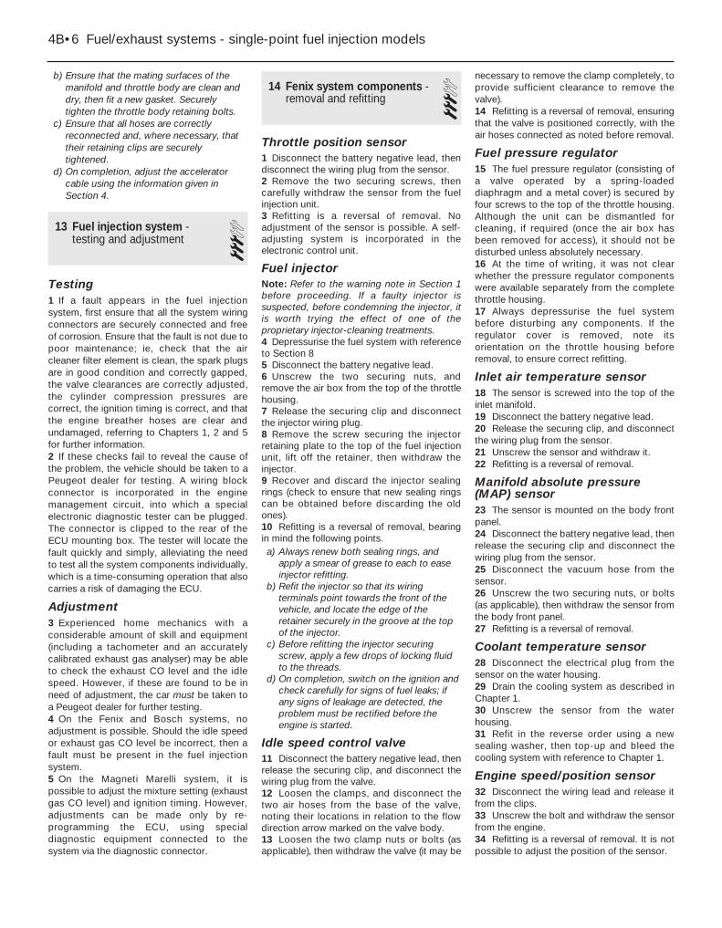
b) Ensure that the mating surfaces of themanifold and throttle body are clean anddry, then fit a new gasket. Securelytighten the throttle body retaining bolts.
c) Ensure that all hoses are correctlyreconnected and, where necessary, thattheir retaining clips are securelytightened.
d) On completion, adjust the acceleratorcable using the information given inSection 4.
13 Fuel injection system -testing and adjustment 3
Testing1 If a fault appears in the fuel injectionsystem, first ensure that all the system wiringconnectors are securely connected and freeof corrosion. Ensure that the fault is not due topoor maintenance; ie, check that the aircleaner filter element is clean, the spark plugsare in good condition and correctly gapped,the valve clearances are correctly adjusted,the cylinder compression pressures arecorrect, the ignition timing is correct, and thatthe engine breather hoses are clear andundamaged, referring to Chapters 1, 2 and 5for further information.2 If these checks fail to reveal the cause ofthe problem, the vehicle should be taken to aPeugeot dealer for testing. A wiring blockconnector is incorporated in the enginemanagement circuit, into which a specialelectronic diagnostic tester can be plugged.The connector is clipped to the rear of theECU mounting box. The tester will locate thefault quickly and simply, alleviating the needto test all the system components individually,which is a time-consuming operation that alsocarries a risk of damaging the ECU.
Adjustment3 Experienced home mechanics with aconsiderable amount of skill and equipment(including a tachometer and an accuratelycalibrated exhaust gas analyser) may be ableto check the exhaust CO level and the idlespeed. However, if these are found to be inneed of adjustment, the car must be taken toa Peugeot dealer for further testing.4 On the Fenix and Bosch systems, noadjustment is possible. Should the idle speedor exhaust gas CO level be incorrect, then afault must be present in the fuel injectionsystem.5 On the Magneti Marelli system, it ispossible to adjust the mixture setting (exhaustgas CO level) and ignition timing. However,adjustments can be made only by re-programming the ECU, using specialdiagnostic equipment connected to thesystem via the diagnostic connector.
14 Fenix system components -removal and refitting 3
Throttle position sensor1 Disconnect the battery negative lead, thendisconnect the wiring plug from the sensor.2 Remove the two securing screws, thencarefully withdraw the sensor from the fuelinjection unit.3 Refitting is a reversal of removal. Noadjustment of the sensor is possible. A self-adjusting system is incorporated in theelectronic control unit.
Fuel injectorNote: Refer to the warning note in Section 1before proceeding. If a faulty injector issuspected, before condemning the injector, itis worth trying the effect of one of theproprietary injector-cleaning treatments.4 Depressurise the fuel system with referenceto Section 85 Disconnect the battery negative lead.6 Unscrew the two securing nuts, andremove the air box from the top of the throttlehousing.7 Release the securing clip and disconnectthe injector wiring plug.8 Remove the screw securing the injectorretaining plate to the top of the fuel injectionunit, lift off the retainer, then withdraw theinjector.9 Recover and discard the injector sealingrings (check to ensure that new sealing ringscan be obtained before discarding the oldones).10 Refitting is a reversal of removal, bearingin mind the following points.a) Always renew both sealing rings, and
apply a smear of grease to each to easeinjector refitting.
b) Refit the injector so that its wiringterminals point towards the front of thevehicle, and locate the edge of theretainer securely in the groove at the topof the injector.
c) Before refitting the injector securingscrew, apply a few drops of locking fluidto the threads.
d) On completion, switch on the ignition andcheck carefully for signs of fuel leaks; ifany signs of leakage are detected, theproblem must be rectified before theengine is started.
Idle speed control valve11 Disconnect the battery negative lead, thenrelease the securing clip, and disconnect thewiring plug from the valve.12 Loosen the clamps, and disconnect thetwo air hoses from the base of the valve,noting their locations in relation to the flowdirection arrow marked on the valve body.13 Loosen the two clamp nuts or bolts (asapplicable), then withdraw the valve (it may be
necessary to remove the clamp completely, toprovide sufficient clearance to remove thevalve).14 Refitting is a reversal of removal, ensuringthat the valve is positioned correctly, with theair hoses connected as noted before removal.
Fuel pressure regulator15 The fuel pressure regulator (consisting ofa valve operated by a spring-loadeddiaphragm and a metal cover) is secured byfour screws to the top of the throttle housing.Although the unit can be dismantled forcleaning, if required (once the air box hasbeen removed for access), it should not bedisturbed unless absolutely necessary.16 At the time of writing, it was not clearwhether the pressure regulator componentswere available separately from the completethrottle housing.17 Always depressurise the fuel systembefore disturbing any components. If theregulator cover is removed, note itsorientation on the throttle housing beforeremoval, to ensure correct refitting.
Inlet air temperature sensor18 The sensor is screwed into the top of theinlet manifold.19 Disconnect the battery negative lead.20 Release the securing clip, and disconnectthe wiring plug from the sensor.21 Unscrew the sensor and withdraw it.22 Refitting is a reversal of removal.
Manifold absolute pressure(MAP) sensor23 The sensor is mounted on the body frontpanel.24 Disconnect the battery negative lead, thenrelease the securing clip and disconnect thewiring plug from the sensor.25 Disconnect the vacuum hose from thesensor.26 Unscrew the two securing nuts, or bolts(as applicable), then withdraw the sensor fromthe body front panel.27 Refitting is a reversal of removal.
Coolant temperature sensor28 Disconnect the electrical plug from thesensor on the water housing.29 Drain the cooling system as described inChapter 1.30 Unscrew the sensor from the waterhousing.31 Refit in the reverse order using a newsealing washer, then top-up and bleed thecooling system with reference to Chapter 1.
Engine speed/position sensor32 Disconnect the wiring lead and release itfrom the clips.33 Unscrew the bolt and withdraw the sensorfrom the engine.34 Refitting is a reversal of removal. It is notpossible to adjust the position of the sensor.
4B•6 Fuel/exhaust systems - single-point fuel injection models

15 Bosch Monopoint systemcomponents - removal andrefitting
3Note: Check the availability of individualcomponents with your Peugeot dealer beforedismantling.
Fuel injectorNote: Refer to the warning note in Section 1before proceeding. If a faulty injector issuspected, before condemning the injector, itis worth trying the effect of one of theproprietary injector-cleaning treatments.1 Remove the inlet air temperature sensor asdescribed later in this Section.2 Lift out the injector and recover its lowersealing ring.3 Refitting is a reversal of the removalprocedure ensuring that the injector sealingring(s) and injector cap O-ring are in goodcondition. When refitting the injector capensure that the injector pins are aligned withthe cap terminals, the terminals are marked “+”and “-” for identification (see illustrations).
Fuel pressure regulatorNote: Refer to the warning note in Section 1before proceeding. At the time of writing, thefuel pressure regulator assembly was notavailable separately from the throttle bodyassembly. Refer to a Peugeot dealer for thelatest information. Although the unit can bedismantled for cleaning, if required, it shouldnot be disturbed unless absolutely necessary.4 Disconnect the battery negative terminal.5 Remove the air cleaner-to-throttle bodyduct, using the information given in Section 2.6 Using a marker pen, make alignment marksbetween the regulator cover and throttlebody, then slacken and remove the coverscrews (see illustration). As the screws areslackened, place a clean rag over the cover tocatch any fuel spray which may be released.7 Lift off the cover, then remove the springand withdraw the diaphragm, noting itscorrect fitted orientation. Remove all traces ofdirt and examine the diaphragm for signs ofsplitting. If damage is found, it will probablybe necessary to renew the throttle bodyassembly.
8 Refitting is a reverse of the removalprocedure, ensuring that the diaphragm andcover are fitted the correct way round, andthat the retaining screws are securelytightened.
Idle control stepper motor9 Disconnect the battery negative terminal.10 Depress the retaining clip and disconnectthe wiring connector from the idle controlstepper motor.11 Undo the retaining screws and removethe motor from the front of the throttle body(see illustration).12 Refitting is a reverse of the removalprocedure, ensuring that the motor retainingscrews are securely tightened.
Throttle potentiometer13 The throttle potentiometer is a sealed unit,and under no circumstances should it be
disturbed. For this reason, on some models, itis secured to the throttle body assembly bytamperproof screws. If the throttlepotentiometer is faulty, the complete throttlebody assembly must be renewed - refer toyour Peugeot dealer for the latest information.
Inlet air temperature sensorNote: Refer to the warning note in Section 1before proceeding.14 The inlet air temperature sensor is anintegral part of the throttle body injector cap.To remove the cap, first disconnect thebattery negative terminal, then remove the aircleaner-to-throttle body duct using theinformation given in Section 2.15 Undo the three retaining screws andremove the circular plastic ring from the top ofthe throttle body and recover its sealing ring(see illustrations).16 Depress the retaining clip and disconnect
Fuel/exhaust systems - single-point fuel injection models 4B•7
15.3c On refitting, ensure cap terminalsare aligned with injector pins (arrowed)
15.15a Undo the three retaining screws(arrowed) . . .
15.11 Idle control stepper motor retaining screws (arrowed)
15.6 Fuel pressure regulator retaining screws (arrowed)
15.3b . . . then lift off the cap and withdrawthe injector
15.3a Undo the injector cap screw, notingthe use of rag to catch fuel spray . . .
4B
15.15b . . . then lift off the plastic ring andrecover the sealing ring

the wiring connector from the injector wiringconnector (see illustration).17 Undo the injector cap retaining screw,then lift off the cap and recover the gasketand/or sealing ring (as applicable). Note thatas the cap screw is slackened, place a ragover the injector to catch any fuel spray whichmay be released.18 Refitting is a reversal of the removalprocedure ensuring that the injector capgasket and/or O-ring is in good condition.Take care to ensure that the cap terminals arecorrectly aligned with the injector pins andsecurely tighten the cap retaining screw.
Coolant temperature sensor19 Refer to Chapter 3.
Electronic control unit (ECU)20 The ECU is located in the plastic boxwhich is mounted onto the rear of the batterymounting tray.21 To remove the ECU, first disconnect thebattery.22 Unclip the cover from the box, then lift theretaining clip and disconnect the wiringconnector from the ECU.23 Undo the retaining nut and release therelay unit from the rear of the ECU box.24 Undo the retaining screws and removethe ECU and box assembly from the batterytray. If necessary, undo the retaining screwsand separate the ECU and box.25 Refitting is a reverse of the removalprocedure ensuring that the wiring connectoris securely reconnected.
Fuel injection system relay unit26 The relay unit is mounted onto the rear ofthe ECU plastic box which is situated directlybehind the battery.27 To remove the relay unit, first disconnectthe battery.28 Undo the retaining nut, then disconnectthe wiring connector and remove the relay unitfrom the vehicle.29 Refitting is the reverse of removal,ensuring that the relay unit is securely clippedin position.
Crankshaft sensor30 The crankshaft sensor is situated on thefront face of the transmission (clutch) housing.
31 To remove the sensor, first disconnect thebattery negative terminal.32 Trace the wiring back from the sensor tothe wiring connector, and disconnect it fromthe main harness.33 Prise out the rubber grommet, then undothe retaining bolt and withdraw the sensorfrom the transmission.34 Refitting is a reverse of the removalprocedure. Ensure that the sensor retainingbolt is securely tightened, and that thegrommet is correctly seated in thetransmission housing.
Vehicle speed sensor35 The vehicle speed sensor is an integralpart of the speedometer drive housing. Referto Chapter 7A, Section 7 for removal andrefitting details.
16 Magneti Marelli systemcomponents - removal andrefitting
3Note: Check the availability of individualcomponents with your Peugeot dealer beforedismantling.
Fuel injectorNote: Refer to the warning note in Section 1before proceeding.Note: If a faulty injector is suspected, beforecondemning the injector, it is worth trying theeffect of one of the proprietary injector-cleaning treatments. If this fails, the vehicleshould be taken to a Peugeot dealer fortesting using the appropriate specialistequipment. At the time of writing, it appearsthat neither the fuel injector nor its seals areavailable separately and, if faulty, thecomplete upper throttle body assembly mustbe renewed. Refer to your Peugeot dealer forfurther information on parts availability.1 Disconnect the battery negative terminal.2 Remove the air cleaner-to-throttle bodyduct using the information given in Section 2.3 Release the retaining tangs and disconnectthe injector wiring connector (seeillustration).4 Undo the retaining screw, then remove theretaining clip and lift the injector out of the
housing, noting its sealing ring. Note that asthe screw is slackened, place a rag over theinjector to catch any fuel spray which may bereleased.5 Refitting is a reverse of the removalprocedure ensuring that the injector sealingring is in good condition.
Fuel pressure regulatorNote: Refer to the warning note at the start ofthis Section before proceeding.Note: At the time of writing, it appears that thefuel pressure regulator is not availableseparately. If the fuel pressure regulatorassembly is faulty, the complete upper throttlebody assembly must be renewed. Refer to aPeugeot dealer for further information on partsavailability. Although the unit can bedismantled for cleaning, if required, it shouldnot be disturbed unless absolutely necessary.6 Disconnect the battery negative terminal.7 Remove the air cleaner-to-throttle bodyduct using the information given in Section 2.8 Using a suitable marker pen, makealignment marks between the regulator coverand throttle body, then undo the four retainingscrews. Note that as the screws areslackened, place a rag over the cover to catchany fuel spray which may be released.9 Lift off the cover, then remove the springand withdraw the diaphragm whilst noting itscorrect fitted orientation. Remove all traces ofdirt and examine the diaphragm for splitting. Ifdamage is found, it will be necessary to renewthe complete upper throttle body assembly asdescribed earlier in this Section.10 Refitting is a reverse of the removalprocedure ensuring that the diaphragm andcover are fitted the correct way around andthe retaining screws are securely tightened.
Idle control stepper motor11 Disconnect the battery negative terminal.12 To remove the stepper motor, depress theretaining tabs and disconnect the wiringconnector. Undo the two retaining screws andwithdraw the motor from the side of thethrottle body assembly.13 Refitting is a reverse of removal.
Throttle potentiometer14 Disconnect the battery negative terminal,then depress the retaining tabs anddisconnect the wiring connect from thethrottle potentiometer (see illustration).15 Undo the two retaining screws andremove the throttle potentiometer from theside of the throttle body assembly.16 Refitting is a reversal of the removalprocedure ensuring that the throttlepotentiometer tang is correctly engaged withthe throttle spindle.
Inlet air temperature sensor17 The inlet air temperature sensor isscrewed into the underside of the upperthrottle body where it is situated on the left-hand side of the fuel injector.
4B•8 Fuel/exhaust systems - single-point fuel injection models
15.16 Disconnecting the injector wiringconnector. Injector screw is arrowed
16.3 Injector wiring connector (arrowed)

18 To remove the sensor, first disconnect thebattery negative terminal.19 Disconnect the wiring connector, thenundo the retaining screw and remove the inletair temperature sensor from the throttle body.Note: The sensor retaining screw is verydifficult to reach. If it proves impossible tounscrew, the throttle body will have to beremoved to permit sensor removal.20 Refitting is a reverse of removal.
Manifold absolute pressure(MAP) sensor21 The MAP sensor is mounted onto abracket which is situated on the enginecompartment bulkhead, behind the throttlebody.22 To remove the sensor, first disconnect thebattery negative terminal.23 Slacken and remove the three retainingbolts, then free the MAP sensor from thebracket. Disconnect the wiring connector andvacuum hose and remove the sensor from theengine compartment.24 Refitting is a reversal of the removalprocedure.
Coolant temperature sensor25 Refer to Chapter 3.
Crankshaft sensor26 Refer to Section 14.
Electronic control unit (ECU)27 Refer to Section 14.
Fuel injection system relay unit28 Refer to Section 14.
Throttle body heating element29 The throttle body heating element issituated in the front of the throttle body.30 To remove the element, first disconnectthe battery negative terminal.31 Remove the air cleaner housing-to-throttle body duct using the information givenin Section 2.32 Disconnect the wiring connectors fromthe inlet air temperature sensor and theinjector. Also disconnect the main wiringconnector from the throttle body and free theconnector from its mounting bracket.33 Undo the retaining screws and free theaccelerator mounting bracket from the throttlebody. As the bracket is released, recover thespring from the front of the heating element.34 Ease the heating element out from thethrottle housing and remove it along with thewiring connector and wiring harness. Examinethe O-ring for signs of damage ordeterioration and renew if necessary.35 Refitting is a reversal of removal; wherenecessary, use a new O-ring.
17 Inlet manifold - removal and refitting 3
Removal1 Remove the throttle body (Section 12).2 Drain the cooling system (see Chapter 1).3 Slacken the retaining clip and disconnectthe coolant hose(s) from the manifold.4 Slacken the retaining clip and disconnectthe vacuum servo unit hose from the left-handside of the manifold.5 Make a final check that all the necessaryvacuum/breather hoses have beendisconnected from the manifold.6 Unscrew the retaining nuts, thenmanoeuvre the manifold away from the headand out of the engine compartment. Note thatthere is no manifold gasket.
Refitting7 Refitting is the reverse of the removalprocedure, noting the following points:a) Ensure that the manifold and cylinder
head mating surfaces are clean and dry,and apply a thin coating of suitable
sealing compound to the manifold matingsurface. Refit the manifold and tighten itsretaining nuts to the specified torque.
b) Ensure that all relevant hoses arereconnected to their original positions andsecurely held (where necessary) by theirretaining clips.
c) Refit the throttle body as described inSection 12.
d) On completion, refill the cooling systemas described in Chapter 1.
18 Exhaust manifold - removal and refitting 3
Removal1 Refer to Chapter 4A, Section 15, noting thatthe lambda (oxygen) sensor wiring connectorsshould be disconnected. Alternatively, caremust be taken to support the front pipe, toavoid any strain being placed on the sensorwiring.
Refitting2 Refitting is the reverse of the removalprocedure, noting the following points:
a) Examine all the exhaust manifold studs forsigns of damage and corrosion; removeall traces of corrosion, and repair orrenew any damaged studs.
b) Ensure that the manifold and cylinderhead sealing faces are clean and flat, andfit the new manifold gaskets. Tighten themanifold retaining nuts to the specifiedtorque.
c) Reconnect the front pipe to the manifold.
19 Exhaust system - general information, removaland refitting
3Refer to Chapter 4A, Section 16, however
note that it will be necessary to disconnectthe lambda (oxygen) sensor wiring connectorsin order to remove the front pipe/completesystem. On refitting, ensure that the sensorwiring is retained by all the relevant retainingclips so that it is in no danger of contactingthe hot exhaust/engine.
Fuel/exhaust systems - single-point fuel injection models 4B•9
4B
16.14 Throttle potentiometer wiringconnector (arrowed)

4CSystem typeXU5 (BFZ), XU7 (LFZ), XU10 (RFX), XU10 (R6D) engine . . . . . . . . . . . . . Magneti Marelli 8P multi-pointXU5 (BFZ) engine . . . . . . . . . . . . . . . . . . . . . . . . . . . . . . . . . . . . . . . . . . Sagem-Lucas 4GJ multi-pointXU7 (LFZ) engine . . . . . . . . . . . . . . . . . . . . . . . . . . . . . . . . . . . . . . . . . . Bosch Motronic MP5.1 multi-pointXU9 (D6A and D6D) engine . . . . . . . . . . . . . . . . . . . . . . . . . . . . . . . . . . Bosch L3.1-Jetronic multi-pointXU9 (D6D) engine . . . . . . . . . . . . . . . . . . . . . . . . . . . . . . . . . . . . . . . . . . Bosch Motronic MP3.1 multi-pointXU9 (DKZ and DFZ) engine . . . . . . . . . . . . . . . . . . . . . . . . . . . . . . . . . . Bosch LU2-Jetronic multi-pointXU9 (DKZ and DFV), XU9 (DFW 16-valve) engine . . . . . . . . . . . . . . . . . Bosch Motronic M1.3 multi-pointXU9 (D6C) 16-valve engine . . . . . . . . . . . . . . . . . . . . . . . . . . . . . . . . . . . Bosch Motronic ML4.1 multi-pointXU10 (RFY 16-valve), XU10 (RFT) engine . . . . . . . . . . . . . . . . . . . . . . . . Bosch Motronic MP3.2 multi-point
Fuel system dataFuel pump type . . . . . . . . . . . . . . . . . . . . . . . . . . . . . . . . . . . . . . . . . . . . Electric, external (early models) or internal (later models)Fuel pump regulated constant pressure (at specified idle speed):
Bosch L3.1 system . . . . . . . . . . . . . . . . . . . . . . . . . . . . . . . . . . . . . . . 2.5 barsOther Bosch systems . . . . . . . . . . . . . . . . . . . . . . . . . . . . . . . . . . . . . 3.0 ± 0.2 barsMagneti Marelli system . . . . . . . . . . . . . . . . . . . . . . . . . . . . . . . . . . . . 2.5 ± 0.2 barsSagem-Lucas system . . . . . . . . . . . . . . . . . . . . . . . . . . . . . . . . . . . . . Not available
Specified idle speed:Bosch L3.1 system . . . . . . . . . . . . . . . . . . . . . . . . . . . . . . . . . . . . . . . 925 ± 25 rpmOther systems . . . . . . . . . . . . . . . . . . . . . . . . . . . . . . . . . . . . . . . . . . . 850 ± 50 rpm (not adjustable - controlled by ECU)
Idle mixture CO content . . . . . . . . . . . . . . . . . . . . . . . . . . . . . . . . . . . . . Less than 1.0 % (not adjustable- controlled by ECU)
Recommended fuelMinimum octane rating:
TU3 (K1A), TU3A (K1G), XU92C (D2D), XU9J2 (D6A),XU9J4 (D6C), XU52C (B2A) engines . . . . . . . . . . . . . . . . . . . . . . . . . . 97 RON leaded*All other engines . . . . . . . . . . . . . . . . . . . . . . . . . . . . . . . . . . . . . . . . . 95 RON unleaded (UK unleaded premium). Leaded fuel must not be
used on models with a catalytic converter*It may be possible to use unleaded if the ignition is retarded by 3° - check with your Peugeot dealer.
Chapter 4 Part C: Fuel/exhaust systems -multi-point fuel injection models
ACAV inlet system (16-valve models) - general information, removal and refitting . . . . . . . . . . . . . . . . . . .19
Accelerator cable - removal, refitting and adjustment . . . . . . . . . . . . .3Accelerator pedal - removal and refitting . . . . . . . . . . . . . . . . . . . . . . .4Air cleaner assembly and inlet ducts - removal and refitting . . . . . . . .2Air cleaner filter element renewal . . . . . . . . . . . . . . . . . .See Chapter 1Bosch L3.1-Jetronic system components -
removal, refitting and adjustments . . . . . . . . . . . . . . . . . . . . . . . . .14Bosch LU2-Jetronic system components -
removal, refitting and adjustments . . . . . . . . . . . . . . . . . . . . . . . . .15Bosch Motronic system components -
removal, refitting and adjustments . . . . . . . . . . . . . . . . . . . . . . . . .16Electronic control unit - removal and refitting . . . . . . . . . . . . . . . . . .13Exhaust manifold - removal and refitting . . . . . . . . . . . . . . . . . . . . . .20Exhaust system check . . . . . . . . . . . . . . . . . . . . . . . . . . .See Chapter 1
Exhaust system - general information, removal and refitting . . . . . . .21Fuel filter renewal . . . . . . . . . . . . . . . . . . . . . . . . . . . . . . .See Chapter 1Fuel gauge sender unit - removal and refitting . . . . . . . . . . . . . . . . . . .9Fuel injection system - depressurisation . . . . . . . . . . . . . . . . . . . . . . .7Fuel injection system - testing and adjustment . . . . . . . . . . . . . . . . .11Fuel injection systems - general information . . . . . . . . . . . . . . . . . . . .6Fuel pump - removal and refitting . . . . . . . . . . . . . . . . . . . . . . . . . . . .8Fuel tank - removal and refitting . . . . . . . . . . . . . . . . . . . . . . . . . . . . .10General information . . . . . . . . . . . . . . . . . . . . . . . . . . . . . . . . . . . . . . .1Idle speed and mixture adjustment . . . . . . . . . . . . . . . . .See Chapter 1Inlet manifold - removal and refitting . . . . . . . . . . . . . . . . . . . . . . . . .18Magneti Marelli system components -
removal, refitting and adjustments . . . . . . . . . . . . . . . . . . . . . . . . .17Throttle housing - removal and refitting . . . . . . . . . . . . . . . . . . . . . . .12Unleaded petrol - general information and usage . . . . . . . . . . . . . . . .5
4C•1
Easy, suitable fornovice with littleexperience
Fairly easy, suitablefor beginner withsome experience
Fairly difficult,suitable for competentDIY mechanic
Difficult, suitable forexperienced DIYmechanic
Very difficult,suitable for expertDIY or professional
Degrees of difficulty
Specifications
Contents
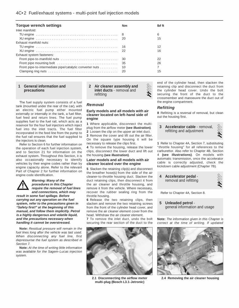
1 General information andprecautions
The fuel supply system consists of a fueltank (mounted under the rear of the car), withan electric fuel pump either mountedexternally or internally in the tank, a fuel filter,fuel feed and return lines. The fuel pumpsupplies fuel to the fuel rail, which acts as areservoir for the four fuel injectors which injectfuel into the inlet tracts. The fuel filterincorporated in the feed line from the pump tothe fuel rail ensures that the fuel supplied tothe injectors is clean.
Refer to Section 6 for further information onthe operation of each fuel injection system,and to Section 21 for information on theexhaust system. Throughout this Section, it isalso occasionally necessary to identifyvehicles by their engine codes rather than byengine capacity alone. Refer to the relevantPart of Chapter 2 for further information onengine code identification.
Note: Residual pressure will remain in thefuel lines long after the vehicle was last used.When disconnecting any fuel line, firstdepressurise the fuel system as described inSection 7.
Note: At the time of writing little informationwas available for the Sagem-Lucas injectionsystem.
2 Air cleaner assembly andinlet ducts - removal andrefitting
2Removal
Early models and all models with aircleaner located on left-hand side ofengine1 Where applicable, disconnect the multi-plug from the airflow meter (see illustration).2 Loosen the clip on the upper air inlet duct.3 Remove the cover and lift out the air filter.On the square type housing it will benecessary to release the clips first.4 To remove the housing, release the lowerclips, disconnect the lower duct and lift outthe housing (see illustration).
Later models and all models with aircleaner located over the engine5 Slacken the retaining clip(s) and disconnectthe breather hose(s) from the side of the aircleaner-to-throttle housing duct. Slacken theduct retaining clips, then disconnect it fromthe air cleaner and throttle housing, andremove it from the vehicle. Where necessary,recover the rubber sealing ring from thethrottle housing.6 Release the two retaining clips, thenslacken and remove the two retaining screwsfrom the front of the cylinder head cover, andremove the air cleaner element cover from thehead. Withdraw the air cleaner element.7 To remove the inlet duct, undo the boltsecuring the rear section of the duct to the
end of the cylinder head, then slacken theretaining clip and disconnect the duct fromthe cylinder head cover. Undo the boltsecuring the front of the duct to thecrossmember and manoeuvre the duct out ofthe engine compartment.
Refitting8 Refitting is a reversal of removal, but cleanout the housing first.
3 Accelerator cable - removal,refitting and adjustment 2
1 Refer to Chapter 4A, Section 7, substituting“throttle housing” for all references to thecarburettor. Also refer to Chapter 4B, Section4 (see illustrations). On models withautomatic transmission, once the acceleratorcable is correctly adjusted, check thekickdown cable adjustment (Chapter 7B).
4 Accelerator pedal - removal and refitting 2
Refer to Chapter 4A, Section 8.
5 Unleaded petrol - general information and usage
Note: The information given in this Chapter iscorrect at the time of writing. If updated
2.4 Removing the air cleaner housing2.1 Disconnecting the airflow meter multi-plug (Bosch L3.1-Jetronic)
Torque wrench settings Nm lbf ftInlet manifold:
TU engine . . . . . . . . . . . . . . . . . . . . . . . . . . . . . . . . . . . . . . . . . . . . . . 8 6XU engine . . . . . . . . . . . . . . . . . . . . . . . . . . . . . . . . . . . . . . . . . . . . . . 20 15
Exhaust manifold nuts:TU engine . . . . . . . . . . . . . . . . . . . . . . . . . . . . . . . . . . . . . . . . . . . . . . 16 12XU engine . . . . . . . . . . . . . . . . . . . . . . . . . . . . . . . . . . . . . . . . . . . . . . 22 16
Exhaust system fasteners:Front pipe-to-manifold nuts . . . . . . . . . . . . . . . . . . . . . . . . . . . . . . . . 30 22Front pipe mounting bolt . . . . . . . . . . . . . . . . . . . . . . . . . . . . . . . . . . 35 26Front pipe-to-intermediate pipe/catalytic converter nuts . . . . . . . . . . 10 7Clamping ring nuts . . . . . . . . . . . . . . . . . . . . . . . . . . . . . . . . . . . . . . . 20 15
4C•2 Fuel/exhaust systems - multi-point fuel injection models
Warning: Many of theprocedures in this Chapterrequire the removal of fuel linesand connections, which may
result in some fuel spillage. Beforecarrying out any operation on the fuelsystem, refer to the precautions given in“Safety first!” at the beginning of thismanual, and follow them implicitly. Petrolis a highly dangerous and volatile liquid,and the precautions necessary whenhandling it cannot be overstressed.

information is thought to be required, checkwith a Peugeot dealer. If travelling abroad,consult one of the motoring organisations (or asimilar authority) for advice on the fuelavailable.
The fuel recommended by Peugeot is givenin the Specifications Section of this Chapter,followed by the equivalent petrol currently onsale in the UK.
All multi-point injection models aredesigned to run on fuel with a minimumoctane rating of 95 (RON). All models with acatalytic converter must be run on unleadedfuel only. Under no circumstances shouldleaded fuel (UK “4-star”) be used, as this maydamage the converter.
6 Fuel injection systems -general information
Note: On later models the fuel injection ECUis of the “self-learning” type, meaning that as itoperates, it also monitors and stores thesettings which give optimum engineperformance under all operating conditions.When the battery is disconnected, thesesettings are lost and the ECU reverts to thebase settings programmed into its memory atthe factory. On restarting, this may lead to theengine running/idling roughly for a short while,until the ECU has re-learned the optimumsettings. This process is best accomplished bytaking the vehicle on a road test (forapproximately 15 minutes), covering all enginespeeds and loads, concentrating mainly in the2500 to 3500 rpm region.
Bosch L3.1 (Jetronic) system1 The Bosch L3.1 fuel injection system is ofthe intermittent type operating under lowpressure. Fuel is drawn from the rear-mounted fuel tank by an externally-mountedfuel pump and delivered through an in-linefilter to the injectors. A pressure regulatormounted on the outlet side of the fuel rail, andconnected by pipe to the inlet manifold tosense vacuum, maintains a constant pressureat the injectors according to the depression inthe inlet manifold, returning excess fuel to thefuel tank.2 A pulse damper on the inlet side of the fuel
rail damps out the pressure pulses caused bythe operation of the injectors.3 The electronic control unit (ECU) andairflow meter are mounted on the air filterhousing. The ECU uses signals from varioussensors to determine the opening period ofthe injectors for any given engine operatingcondition. The inputs are as follows.a) Amount of air being drawn in by the
engine via the airflow meter.b) Inlet air temperature via the thermistor
mounted in the airflow meter.c) Engine speed and angular position via the
injection (coolant) thermistor.d) Throttle position via the throttle switch
unit.4 The injectors operate simultaneously,spraying fuel onto the inlet side of the inletvalves.5 A supplementary air device is fitted to thesystem to compensate for the extra fuelrequired during cold start conditions.
Bosch LU2-Jetronic system6 The principle of operation of the LU2-Jetronic system is similar to that described forthe L3.1-Jetronic system but with thefollowing differences.a) A single-barrel throttle body is fitted.b) An oxygen sensor is fitted.c) A catalytic converter is fitted.
7 The most significant difference is that theLU2-Jetronic system incorporates an oxygensensor in the exhaust system, which enablesthe electronic control unit to carry out finefuel/air mixture adjustment to allow the use ofa catalytic converter.
Bosch Motronic MP3.1 system8 The principle of operation of the MotronicMP3.1 system is similar to that described forthe L3.1-Jetronic system but with thefollowing differences.a) The ECU controls the ignition system in
addition to the fuel injection system,providing an integrated enginemanagement system.
b) A static (distributorless)ignition system isused.
c) An inlet air temperature sensor and amanifold absolute pressure (MAP) sensorare used in place of the airflow meter.
d) An engine speed/position sensor is usedto provide information on engine speedand crankshaft position.
Bosch Motronic M1.3 system9 The principle of operation of the MotronicM1.3 system is similar to that described forthe L3.1-Jetronic system but with thefollowing differences.a) The ECU controls the ignition system and
the fuel injection system, providing anintegrated engine management system.
b) An engine speed/position sensor is usedto provide information on engine speedand crankshaft position.
c) The ECU controls the idle speed under allengine operating conditions, via an idlespeed control valve. No supplementary airdevice is fitted.
d) An oxygen sensor is fitted to enable theECU to control the air/fuel mixture veryaccurately, allowing the use of a catalyticconverter.
e) A knock sensor, mounted in the cylinderblock is used to detect the onset ofengine knock, or pre-ignition. Thisenables the ECU to select the optimumignition advance for the prevailing engineoperating conditions without risk ofdamage to the engine.
Bosch Motronic ML4.1 system10 The principle of operation of the MotronicML4.1 system is similar to that described forthe L3.1-Jetronic system but with thefollowing differences.a) The ECU incorporates a cold start
function and a fault memory.b) The mixture adjustment by-pass screw is
replaced by an adjustment screw on thethrottle potentiometer.
c) The throttle housing has a double body.d) Idle speed is maintained at a
predetermined level (regardless of load)by an idle speed valve.
Bosch Motronic MP5.1 system11 The Bosch Motronic MP5.1 enginemanagement (fuel injection/ignition) systemincorporates a closed-loop catalytic converterand an evaporative emission control system,and complies with the very latest emissioncontrol standards. Refer to Chapter 5 fordetaisl on the ignition side of the system; thefuel side of the system operates as follows.12 The fuel pump (which is immersed in thefuel tank) supplies fuel from the tank to thefuel rail, via a filter mounted underneath therear of the vehicle. Fuel supply pressure iscontrolled by the pressure regulator in the fuelrail. When the optimum operating pressure ofthe fuel system is exceeded, the regulatorallows excess fuel to return to the tank.13 The electrical control system consists ofthe ECU, along with the following sensors:a) Throttle potentiometer - informs the ECU
of the throttle position, and the rate ofthrottle opening/closing.
Fuel/exhaust systems - multi-point fuel injection models 4C•3
3.1b Disconnecting the accelerator cableend fitting (Bosch L3.1 system)
3.1a Disconnecting accelerator cable fromthe throttle quadrant (Bosch L3.1 system)
4C

b) Coolant temperature sensor - informs theECU of engine temperature.
c) Inlet air temperature sensor - informs theECU of the temperature of the air passingthrough the throttle housing.
d) Lambda sensor - informs the ECU of theoxygen content of the exhaust gases(explained in Part D of this Chapter).
e) Crankshaft sensor - informs the ECU ofcrankshaft position and speed of rotation.
f) Manifold Absolute Pressure (MAP) sensor- informs the ECU of the load on theengine (expressed in terms of inletmanifold vacuum).
g) Vehicle speed sensor - informs the ECUof the vehicle speed.
14 All the above signals are analysed by theECU which selects the fuelling responseappropriate to those values. The ECU controlsthe fuel injectors (varying the pulse width - thelength of time the injectors are held open - toprovide a richer or weaker mixture, asappropriate). The mixture is constantly variedby the ECU, to provide the best setting forcranking, starting (with either a hot or coldengine), warm-up, idle, cruising andacceleration.15 The ECU also has full control over theengine idle speed, via an auxiliary air valvewhich bypasses the throttle valve. When thethrottle valve is closed, the ECU controls theopening of the valve, which in turn regulatesthe amount of air entering the manifold, andso controls the idle speed.16 The ECU also controls the exhaust andevaporative emission control systems, whichare described in Part D of this Chapter.17 An electric heating element is fitted to thethrottle housing; the heater is supplied withcurrent by the ECU, and warms the throttlehousing on cold starts to prevent possibleicing of the throttle valve.18 If there is an abnormality in any of thereadings obtained from either the coolanttemperature sensor, the inlet air temperaturesensor or the lambda sensor, the ECU entersits back-up mode. In this event, it ignores theabnormal sensor signal and assumes a pre-programmed value which will allow the engineto continue running (albeit at reducedefficiency). If the ECU enters this back-upmode, the warning light on the instrumentpanel will come on, and the relevant faultcode will be stored in the ECU memory.19 If the warning light comes on, the vehicleshould be taken to a Peugeot dealer at theearliest opportunity. A complete test of theengine management system can then becarried out, using a special electronicdiagnostic test unit which is simply pluggedinto the system’s diagnostic connector.
Magneti Marelli 8P system20 The Magneti Marelli 8P enginemanagement (fuel injection/ignition) system isvery similar in operation to the Bosch MP5.1system described above, apart from the idlespeed control system.
21 On the Magneti Marelli system, the idlespeed is controlled by the ECU via a steppermotor fitted to the throttle housing. The motorhas a pushrod controlling the opening of anair passage which bypasses the throttle valve.When the throttle valve is closed, the ECUcontrols the movement of the motor pushrod,which regulates the amount of air which flowsthrough the throttle housing passage, socontrolling the idle speed. The bypasspassage is also used as an additional airsupply during cold starting.
7 Fuel injection system - depressurisation 2
Note: Refer to the warning note in Section 1before proceeding.
1 The fuel system referred to in this Section isdefined as the tank-mounted fuel pump, thefuel filter, the fuel injectors, the fuel rail andthe pressure regulator, and the metal pipesand flexible hoses of the fuel lines betweenthese components. All these contain fuelwhich will be under pressure while the engineis running, and/or while the ignition isswitched on. The pressure will remain forsome time after the ignition has beenswitched off, and must be relieved in acontrolled fashion when any of thesecomponents are disturbed for servicing work.2 Disconnect the battery negative terminal.3 Place a container beneath the connection/union to be disconnected, and have a largerag ready to soak up any escaping fuel notbeing caught by the container.4 Slowly loosen the connection or union nutto avoid a sudden release of pressure, andwrap the rag around the connection, to catchany fuel spray. Once the pressure is released,disconnect the fuel line. Plug the pipe ends, tominimise fuel loss and prevent the entry of dirtinto the fuel system.
8 Fuel pump - removal and refitting 3
Refer to Chapter 4B, Section 9.
9 Fuel gauge sender unit -removal and refitting 3
Refer to Chapter 4A, Section 5. Where thefuel pump is mounted externally there are nofuel pipe connections to the sender unit.
10 Fuel tank - removal and refitting 3
Refer to Chapter 4A, Section 6, noting thatit will be necessary to depressurise the fuelsystem before the feed and return hoses aredisconnected (see Section 7). It will also benecessary to disconnect the wiring connectorfrom the internal fuel pump before loweringthe tank out of position.
11 Fuel injection system -testing and adjustment 2
Testing1 If a fault appears in the fuel injectionsystem, first ensure that all the system wiringconnectors are securely connected and freeof corrosion. Ensure that the fault is not due topoor maintenance; ie, check that the aircleaner filter element is clean, the spark plugsare in good condition and correctly gapped,the cylinder compression pressures arecorrect, the ignition timing is correct, and thatthe engine breather hoses are clear andundamaged, referring to Chapters 1, 2 and 5for further information.2 If these checks fail to reveal the cause ofthe problem, the vehicle should be taken to asuitably-equipped Peugeot dealer for testing.On later models a wiring block connector isincorporated in the engine managementcircuit, into which a special electronicdiagnostic tester can be plugged. The testerwill locate the fault quickly and simply,alleviating the need to test all the systemcomponents individually, which is a time-consuming operation that carries a risk ofdamaging the ECU.
Adjustment
Bosch L3.1 and MP3.1 systems3 Before attempting to adjust the idle speedor mixture (CO), ensure that the followingconditions are met.a) Ignition system is in good condition and
correctly adjusted.b) Air filter is clean.c) Throttle initial positions correctly adjusted.d) Throttle switch correctly adjusted.e) Engine must be hot, the cooling fan
having cut in at least once, but the fanmust not be running during the actualadjustment.
4 Idle speed is adjusted using the idle speedadjustment screw on the throttle housing (seeillustration). Turn the screw clockwise todecrease the idle speed, or anti-clockwise toincrease the speed.5 To adjust the idle mixture, prise out thetamperproof cap covering the mixture (CO)adjustment screw on the airflow meter unit.
4C•4 Fuel/exhaust systems - multi-point fuel injection models
Warning: The followingprocedure will merely relievethe pressure in the fuel system -remember that fuel will still be
present in the system components andtake precautions accordingly beforedisconnecting any of them.
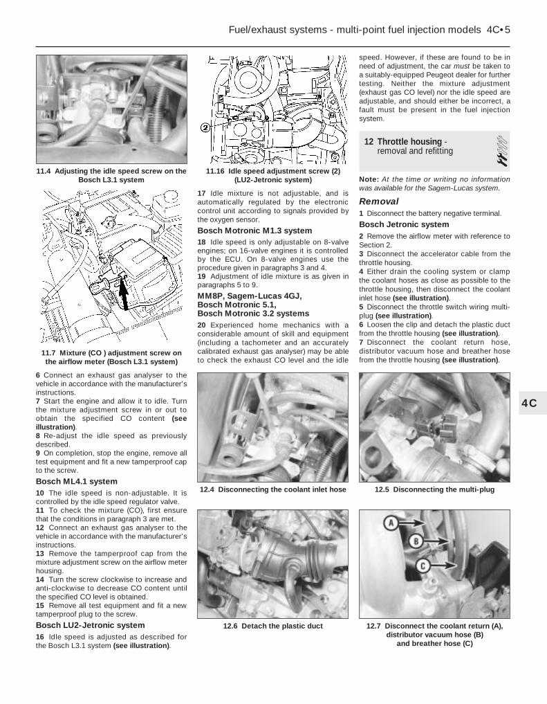
6 Connect an exhaust gas analyser to thevehicle in accordance with the manufacturer’sinstructions.7 Start the engine and allow it to idle. Turnthe mixture adjustment screw in or out toobtain the specified CO content (seeillustration).8 Re-adjust the idle speed as previouslydescribed.9 On completion, stop the engine, remove alltest equipment and fit a new tamperproof capto the screw.
Bosch ML4.1 system10 The idle speed is non-adjustable. It iscontrolled by the idle speed regulator valve.11 To check the mixture (CO), first ensurethat the conditions in paragraph 3 are met.12 Connect an exhaust gas analyser to thevehicle in accordance with the manufacturer’sinstructions.13 Remove the tamperproof cap from themixture adjustment screw on the airflow meterhousing.14 Turn the screw clockwise to increase andanti-clockwise to decrease CO content untilthe specified CO level is obtained.15 Remove all test equipment and fit a newtamperproof plug to the screw.
Bosch LU2-Jetronic system16 Idle speed is adjusted as described forthe Bosch L3.1 system (see illustration).
17 Idle mixture is not adjustable, and isautomatically regulated by the electroniccontrol unit according to signals provided bythe oxygen sensor.
Bosch Motronic M1.3 system18 Idle speed is only adjustable on 8-valveengines; on 16-valve engines it is controlledby the ECU. On 8-valve engines use theprocedure given in paragraphs 3 and 4.19 Adjustment of idle mixture is as given inparagraphs 5 to 9.
MM8P, Sagem-Lucas 4GJ, Bosch Motronic 5.1, Bosch Motronic 3.2 systems20 Experienced home mechanics with aconsiderable amount of skill and equipment(including a tachometer and an accuratelycalibrated exhaust gas analyser) may be ableto check the exhaust CO level and the idle
speed. However, if these are found to be inneed of adjustment, the car must be taken toa suitably-equipped Peugeot dealer for furthertesting. Neither the mixture adjustment(exhaust gas CO level) nor the idle speed areadjustable, and should either be incorrect, afault must be present in the fuel injectionsystem.
12 Throttle housing - removal and refitting 2
Note: At the time or writing no informationwas available for the Sagem-Lucas system.
Removal1 Disconnect the battery negative terminal.
Bosch Jetronic system2 Remove the airflow meter with reference toSection 2.3 Disconnect the accelerator cable from thethrottle housing.4 Either drain the cooling system or clampthe coolant hoses as close as possible to thethrottle housing, then disconnect the coolantinlet hose (see illustration).5 Disconnect the throttle switch wiring multi-plug (see illustration).6 Loosen the clip and detach the plastic ductfrom the throttle housing (see illustration).7 Disconnect the coolant return hose,distributor vacuum hose and breather hosefrom the throttle housing (see illustration).
Fuel/exhaust systems - multi-point fuel injection models 4C•5
11.16 Idle speed adjustment screw (2)(LU2-Jetronic system)
12.7 Disconnect the coolant return (A),distributor vacuum hose (B)
and breather hose (C)
12.6 Detach the plastic duct
12.5 Disconnecting the multi-plug12.4 Disconnecting the coolant inlet hose
4C
11.4 Adjusting the idle speed screw on theBosch L3.1 system
11.7 Mixture (CO ) adjustment screw onthe airflow meter (Bosch L3.1 system)

8 Unscrew the Allen bolts and remove thethrottle housing (see illustration).
Bosch LU2-Jetronic system9 Release the securing clip, and disconnectthe wiring plug from the throttle positionswitch.10 Loosen the securing clamp, anddisconnect the air trunking from the front ofthe throttle body.11 Disconnect the accelerator cable.12 Disconnect the vacuum and/or breatherhoses from the throttle body, noting theirlocations to ensure correct refitting.13 Unscrew the three throttle body securingnuts, and recover the washers. Remove thethrottle cable bracket from the top throttlebody securing stud, noting its orientation.
Bosch Motronic system14 Slacken the retaining clip, thendisconnect the inlet duct from the throttlehousing and recover the sealing ring.15 Disconnect the accelerator inner cablefrom the throttle cam, then withdraw the outercable from the mounting bracket, along withits flat washer and spring clip.16 Depress the retaining clip and disconnectthe wiring connector(s) from the throttlepotentiometer, and, where necessary, fromthe electric heating element, the airtemperature sensor.17 Slacken and remove the three retainingscrews and remove the throttle housing fromthe inlet manifold. Recover the O-ring frommanifold and discard it; a new one must beused on refitting.
Magneti Marelli 8P system18 Remove the air cleaner-to-throttlehousing duct as described in Section 2.19 As applicable, carefully lever theaccelerator linkage rod off its throttle housingballjoint, or disconnect the accelerator innercable from the throttle cam, then withdraw theouter cable from the mounting bracket alongwith its flat washer and spring clip. Wherenecessary, also disconnect the kickdowncable as described in Chapter 7B (seeillustration).20 Depress the retaining clips, anddisconnect the wiring connectors from thethrottle potentiometer, the electric heatingelement, the air temperature sensor and idlecontrol stepper motor (as applicable).21 Release the retaining clips (where fitted),and disconnect all the relevant vacuum andbreather hoses from the throttle housing. Makeidentification marks on the hoses, to ensurethey are connected correctly on refitting.22 Slacken and remove the three retainingscrews, and remove the throttle housing fromthe inlet manifold. Remove the O-ring from themanifold, and discard it - a new one must beused on refitting.
Refitting23 Refitting is a reversal of the removalprocedure, noting the following points:a) Fit a new O-ring to the manifold, then refit
the throttle housing and securely tightenits nuts or screws (as applicable).
b) Ensure all hoses are correctly reconnectedand, where necessary, are securely held inposition by the retaining clips.
c) Ensure all wiring is correctly routed, andthe connectors are securely reconnected.
d) On completion, adjust the acceleratorcable as described in Section 3 and,where necessary, the kickdown cable asdescribed in Chapter 7B.
13 Electronic control unit -removal and refitting 3
Removal1 With the exception of the Bosch L3.1-Jetronic system, the electronic control unit is
located behind the engine compartmentbulkhead on the left-hand side. On the L3.1system it is located on the air cleaner coverand is removed by removing the cover asdescribed in Section 2. Proceed as follows forother models.2 To remove the unit first disconnect thebattery negative lead.3 Open the bonnet and unclip the cover fromthe top of the engine compartment bulkhead.4 Release the clip, and disconnect the wiringplug from the electronic control unit.5 Unscrew the clamp bolts or nuts, asapplicable, securing the ECU to the housing,then carefully withdraw the unit from itslocation. On some models, it may benecessary to disconnect the control unitwiring harness earth lead before the unit canbe withdrawn.6 Where applicable, separate the control unitfrom its mounting bracket.
Refitting7 Refitting is a reversal of removal, ensuringthat the wiring harness earth lead is correctlyreconnected where applicable.
14 Bosch L3.1-Jetronic systemcomponents - removal,refitting and adjustments
3Throttle initial position1 Disconnect the accelerator cable andthrottle switch.2 Loosen the throttle switch unit mountingbolts and turn the unit fully anti-clockwise,then tighten the mounting bolts.
Primary barrel3 Prise out the tamperproof cap from thethrottle stop screw and loosen the screw until itis clear of the throttle lever (see illustration).4 Place a 0.05 mm feeler blade between thelever and the screw and tighten the screwuntil it just contacts the feeler blade withouttrapping it (see illustration). The throttle levermust not be moved.
14.4 Adjusting the throttle initial position
4C•6 Fuel/exhaust systems - multi-point fuel injection models
12.8 Removing the throttle housing
14.3 Tamperproof cap covering primarythrottle stop screw (arrowed)
12.19 Accelerator cable and kickdowncable connections on the throttle housing(Magneti Marelli 8P fuel injection system)

5 Remove the feeler blade then turn thescrew in by a further quarter turn. Fit a newtamperproof cap.
Secondary barrel6 The procedure is as described for theprimary barrel but using the secondary throttleadjustment screw (see illustrations).7 On completion of the adjustment, apply adrop of thread locking compound to the headof the adjustment screw.8 Adjust the throttle switch.9 Reconnect the throttle switch andaccelerator cable.
Throttle switch10 To remove the unit, disconnect the multi-plug and unbolt the unit from the throttlehousing.11 To adjust the switch proceed as follows.12 The throttle valve initial opening positionmust be correctly adjusted.
Idling switch13 Loosen the switch bolts and turn itclockwise as far as it will go, then bring it backuntil the switch can be heard to operate (seeillustration).14 Tighten the mounting bolts with theswitch held in this position.15 To check that the adjustment is correct,disconnect the multi-plug and connect anohmmeter to terminals 2 and 18 on theswitch.16 The ohmmeter should read zero ohms.17 Fully depress the accelerator pedal, whenthe ohmmeter should read infinity.18 If these readings are incorrect, re-adjustthe switch.
Full load switch19 Connect the ohmmeter to terminals 3 and18 on the switch. The reading should indicateinfinity.20 Fully depress the accelerator pedal, whenthe reading should be zero ohms.21 If these readings are incorrect, renew thethrottle switch.22 Reconnect the multi-plug.
Airflow meter and ECU23 The airflow meter and ECU are removedas described in Section 2.
Fuel rail and injectorsNote: Refer to the warning note in Section 1before proceeding.Note: If a faulty injector is suspected, beforecondemning the injector, it is worth trying theeffect of one of the proprietary injector-cleaning treatments.24 Depressurise the fuel system.25 Disconnect the sensor pipe on the fuelpressure regulator and remove the bolt fromthe regulator support bracket on the inletmanifold.26 Number the injector electrical plugs thendisconnect them from the injectors.27 Disconnect the inlet and outlet fuel hoses,being prepared for any fuel spillage.28 Unbolt the fuel rail and pull it and theinjectors upward to release them from thecylinder head (see illustrations).29 Pull out the clips securing the injectors to
the fuel rail and pull out the injectors. Numberthem for refitting in the same positions (seeillustration).30 Check the condition of the O-ring sealsand renew them as necessary (seeillustration).31 Clean the injector nozzles using injectorcleaning fluid. Note: Fouling of the injectornozzles can cause the following symptoms.a) Difficult hot starting.b) Persistent stalling.c) Misfiring when cold.d) Misfire when hot between 1000 and
2000 rpm.e) Loss of performance.
32 Refitting is a reversal of removal.
Fuel pressure regulator33 Depressurise the system.34 Disconnect the sensor pipe.35 Disconnect the fuel hose.
Fuel/exhaust systems - multi-point fuel injection models 4C•7
14.13 Throttle switch unit mounting bolts(A) and plug terminal numbers
14.29 Removing an injector from the fuel rail
14.28b . . . and pulling up the rail andinjectors
14.28a Removing a fuel rail bolt . . .
14.6b . . . and viewed from underneath14.6a Secondary throttle adjusting screw(arrowed) . . .
4C
14.30 Injector O-ring seals (arrowed)

36 Remove the bolt from the support bracketon the inlet manifold.37 Unbolt and remove the regulator from thefuel rail (see illustration).38 Refit in reverse order.
Fuel pump damper39 Depressurise the fuel system.40 Disconnect the fuel hose unions from thedamper (see illustration).41 Unscrew the nut securing the damper tothe support bracket and remove the damper.42 Refit in reverse order.
Supplementary air device43 Disconnect the battery then remove thebattery and battery tray.44 Remove the nuts securing the waterhousing to the cylinder head.45 Disconnect the wiring and air hoses fromthe air device (see illustration).46 Tilt the water housing to gain access tothe air device securing bolts and remove thebolts and air device.47 Refit in reverse order.
Injection thermistor48 Disconnect the wiring from the thermistoron the water housing (see illustration).49 Drain the cooling system.50 Unscrew the thermistor from the waterhousing.51 Refit in reverse order, using a new sealingwasher.52 Top-up and bleed the cooling system.
Fuel filter53 Disconnect the battery negative lead.54 Depressurise the fuel system.55 Disconnect the inlet and outlet hoses fromthe filter (see illustration).56 Loosen the rubber mounting strap clampnut and slide the filter from the clamp.57 Refit in reverse order, ensuring anydirectional arrows on the filter are facing thedirection of fuel flow.
15 Bosch LU2-Jetronic systemcomponents - removal,refitting and adjustments
3Throttle initial position1 The throttle initial position is set inproduction, and will not normally requireadjustment unless the throttle housing hasbeen tampered with. Adjustment should beentrusted to a Peugeot dealer.
Throttle switch unit2 Disconnect the battery negative lead.3 Disconnect the wiring plug from the switch.4 Remove the two securing screws, andwithdraw the switch from the throttle body.5 Commence refitting by initially adjusting theswitch as described later.6 Refitting is reversal of removal, but ensurethat the switch wiper engages correctly withthe flats on the end of the throttle spindle.7 The throttle initial position must be correctly
adjusted before attempting to adjust thethrottle switch.8 Slacken the throttle switch securing screws.9 Turn the switch unit fully clockwise, thenturn it slowly back until the idling contacts areheard to close.10 Tighten the securing screws.11 Pull the wiring from the switch, thenconnect an ohmmeter between terminals 2and 18 in the switch - the ohmmeter shouldread zero.12 Operate the throttle linkage, and theohmmeter should read infinity.13 If the readings are not correct, repeat theadjustment.14 Connect an ohmmeter between switchterminals 3 and 18 - the ohmmeter shouldread infinity.15 Fully open the throttle, and the ohmmetershould read zero.16 If the specified readings cannot beobtained, renew the switch.17 Reconnect the switch wiring plug oncompletion.
Airflow meter18 The airflow meter is removed asdescribed in Section 2.
Electronic control unit (ECU)19 Refer to Section 13.
Fuel injectorsNote: Refer to the warning note in Section 1before proceeding.Note: If a faulty injector is suspected, beforecondemning the injector, it is worth trying theeffect of one of the proprietary injector-cleaning treatments.20 Depressurise the fuel system.21 Disconnect the battery negative lead.22 Disconnect the wiring plugs from the fuelinjectors, labelling them if necessary to ensurecorrect refitting.23 Disconnect the vacuum hose from the topof the fuel pressure regulator.24 Unscrew the four bolts securing the fuelrail to the inlet manifold then carefully lift therail, complete with pressure regulator and fuelinjectors, from the inlet manifold, taking carenot to strain any of the hoses or pipes.
4C•8 Fuel/exhaust systems - multi-point fuel injection models
14.37 Regulator-to-fuel rail bolts (arrowed)- assembly removed for clarity
14.45 Disconnecting the supplementaryair device plug
14.55 Fuel filter showing fuel hoses (A)and clamp bolt (B)
14.48 Disconnecting the injectionthermistor wiring
14.40 Fuel pump damper showing fuelhose connections

25 To remove a fuel injector from the fuel rail,carefully remove the metal securing clip, thenpull the injector from the rail. Be prepared forfuel spillage.26 Refitting is a reversal of removal, but usenew injector O-rings.
Fuel pressure regulatorNote: Refer to the warning note in Section 1before proceeding.27 For improved access to the regulatorlower securing nut, remove the fuel rail.28 If not already done, disconnect thevacuum hose from the top of the pressureregulator.29 Slacken the hose clip, and disconnect thefuel return hose from the bottom of thepressure regulator. Be prepared for fuelspillage.30 Unscrew the two bolts securing thepressure regulator to the fuel rail bracketassembly, whilst counterholding the nuts.Note that on some models a hose bracket issecured by the upper bolt.31 Pull the regulator from the end of the fuelrail, and recover the O-ring.32 Refitting is a reversal of removal, but use anew O-ring when refitting the pressureregulator to the fuel rail, and where applicable,use new injector O-rings.
Oxygen sensor33 The sensor is located in the exhaustdownpipe. When handling the sensor, notethat it is fragile; take care not to drop it, anddo not allow it to contact fuel or siliconesubstances.34 Start the engine and run it until it reachesnormal operating temperature, then switch offand disconnect the battery negative lead.35 If access is required from below, jack upthe front of the car and support it on axlestands (see “Jacking and Vehicle Support).36 Release the securing clips, and separatethe two halves of the sensor wiring connector.37 Using a suitable spanner, unscrew it fromthe exhaust downpipe.38 Refitting is a reversal of removal, bearingin mind the following points.a) Apply anti-seize compound to the threads
of the sensor.b) The sensor must be tightened securely;
this will require the use of either a deepsocket, slotted to allow for the sensorwiring, or of a spanner.
16 Bosch Motronic systemcomponents - removal,refitting and adjustments
3Fuel rail and injectorsNote: Refer to the warning note in Section 1before proceeding. If a faulty injector issuspected, before condemning the injector, itis worth trying the effect of one of theproprietary injector-cleaning treatments.
1 Disconnect the battery negative terminal.2 Disconnect the vacuum pipe from the fuelpressure regulator, then slacken and removethe retaining nut and bolt and release thewiring/hose retaining clip from the end of thefuel rail.3 Bearing in mind the information given inSection 7, slacken the retaining clips anddisconnect the fuel feed and return hosesfrom the fuel rail. Where the original crimped-type Peugeot hose clips are still fitted, cutthem and discard; replace them with standardworm-type hose clips on refitting.4 Depress the retaining tangs and disconnectthe wiring connectors from the four injectors.5 Slacken and remove the fuel rail retainingbolts and nuts, then carefully ease the fuel railand injector assembly out from the inletmanifold and remove it from the vehicle.Remove the O-rings from the end of eachinjector and discard them; they must berenewed whenever they are disturbed.6 Slide out the retaining clip(s) and removethe relevant injector(s) from the fuel rail.Remove the upper O-ring from each disturbedinjector and discard; all disturbed O-ringsmust be renewed.7 Refitting is a reversal of the removalprocedure, noting the following points.a) Fit new O-rings to all disturbed injector
unions.b) Apply a smear of engine oil to the O-rings
to aid installation, then ease the injectorsand fuel rail into position ensuring thatnone of the O-rings are displaced.
c) On completion, start the engine andcheck for fuel leaks.
Fuel pressure regulatorNote: Refer to the warning note in Section 1before proceeding.8 Disconnect the vacuum pipe from theregulator. Note that access to the regulator ispoor with the fuel rail in position, if necessary,remove the fuel rail as described earlier, thenremove the regulator.9 Place a wad of rag over the regulator, tocatch any fuel spray which may be released,then remove the retaining clip and ease theregulator out from the fuel rail.10 Refitting is a reversal of the removalprocedure. Examine the regulator seal forsigns of damage or deterioration and renew ifnecessary.
Throttle potentiometer11 Disconnect the battery negative terminal.12 Depress the retaining clip and disconnectthe wiring connector from the throttlepotentiometer.13 Slacken and remove the two retaining
screws, then disengage the potentiometerfrom the throttle valve spindle and remove itfrom the vehicle.14 Refitting is a reversal of the removalprocedure ensuring that the potentiometer iscorrectly engaged with the throttle valvespindle.
Electronic Control Unit (ECU)15 Refer to Section 13.
Idle speed auxiliary air valve16 The auxiliary air valve is mounted onto theunderside of the inlet manifold.17 To remove it, first disconnect the batterynegative terminal.18 Depress the retaining clip and disconnectthe wiring connector from the air valve.19 Slacken the retaining clips and disconnectboth vacuum hoses from the end of theauxiliary air valve.20 Slide the valve out from its mountingrubber and remove it from the enginecompartment.21 Refitting is a reversal of the removalprocedure. Examine the mounting rubber forsigns of deterioration and renew it ifnecessary.
Manifold absolute pressure(MAP) sensor22 The MAP sensor is situated on the right-hand side of the engine compartment where itis mounted onto the wing valance. To removeit, first disconnect the battery negativeterminal.23 Undo the retaining nut and free the MAPsensor from the body.24 Disconnect the wiring connector andvacuum hose and remove the MAP sensorfrom the engine compartment.25 Refitting is the reversal of the removalprocedure.
Coolant temperature sensor26 Refer to Chapter 3.
Inlet air temperature sensor27 The inlet air temperature sensor isscrewed into the top of the air cleanerhousing. To remove the sensor firstdisconnect the battery negative terminal.28 Disconnect the wiring connector, thenunscrew the sensor and remove it from thevehicle.29 Refitting is the reversal of removal.
Crankshaft sensor30 The crankshaft sensor is situated on thefront face of the transmission clutch housing.31 To remove the sensor, first disconnect thebattery negative terminal.32 Trace the wiring back from the sensor tothe wiring connector and disconnect it fromthe main harness.33 Prise out the rubber grommet, then undothe retaining bolt and withdraw the sensorfrom the transmission.34 Refitting is reversal of the removal
Fuel/exhaust systems - multi-point fuel injection models 4C•9
4C
Warning: During the proceduredescribed in this Section it isvery important not to allow fuelto spill into the engine,
otherwise a hydraulic lock may occurcausing extensive engine damage.

procedure ensuring that the sensor retainingbolt is securely tightened and the grommet iscorrectly seated in the transmission housing.
Fuel injection system relay unit35 The relay unit is mounted onto the rear ofthe ECU plastic box which is situated directlybehind the battery.36 To remove the relay unit, first disconnectthe battery.37 Undo the retaining nut, then disconnectthe wiring connector and remove the relay unitfrom the vehicle.38 Refitting is the reverse of removal,ensuring that the relay unit is securely clippedin position.
17 Magneti Marelli systemcomponents - removal,refitting and adjustments
31.8 litre models
Fuel injectorsNote: Refer to the warning note in Section 1before proceeding. If a faulty injector issuspected, before condemning the injector, itis worth trying the effect of one of theproprietary injector-cleaning treatments.1 Disconnect the battery negative terminal.2 Remove the air cleaner-to-throttle housingduct as described in Section 2.3 Undo the two bolts securing the wiring trayto the top of the manifold, and position thetray clear of the injectors.4 Depress the retaining clip(s) and disconnectthe wiring connector(s) from the injector(s).5 Slacken the retaining screw and remove theinjector retaining plate; Nos 1 and 2 injectorsare retained by one plate, Nos 3 and 4 byanother.6 Place a wad of clean rag over the injector,to catch any fuel spray which may bereleased, then carefully ease the relevantinjector(s) out of the manifold. Remove the O-rings from the end of each disturbed injector,and discard them - these must be renewedwhenever they are disturbed.7 On refitting the injectors, fit new O-rings tothe end of each injector. Apply a smear ofengine oil to the O-ring, to aid installation,then ease the injector(s) back into position inthe manifold.8 Ensure each injector connector is correctlypositioned, then refit the retaining plate andsecurely tighten its retaining screw.Reconnect the wiring connector(s) to theinjector(s).9 Refit the wiring tray to the top of themanifold and securely tighten its retainingbolts.10 Refit the air cleaner-to-throttle body ductand reconnect the battery. Start the engineand check the injectors for signs of leakage.
Fuel pressure regulator11 Refer to Section 13.
Throttle potentiometer12 The throttle potentiometer is fitted to theright-hand side of the throttle housing. Toremove the potentiometer, first disconnect thebattery negative terminal.13 Depress the retaining clip and disconnectthe potentiometer wiring connector.14 Slacken and remove the two retainingscrews, and remove the potentiometer fromthe throttle housing.15 Refitting is the reverse of removal,ensuring that the potentiometer is correctlyengaged with the throttle valve spindle.
Electronic Control Unit (ECU)16 Refer to Section 13.
Idle speed control stepper motor17 The idle speed control stepper motor is located on the front of the throttle housing assembly. Before removing themotor, first disconnect the battery negativeterminal.18 Release the retaining clip and disconnectthe wiring connector from the motor.19 Slacken and remove the two retainingscrews, and withdraw the motor from thethrottle housing.20 Refitting is a reversal of the removalprocedure.
Manifold absolute pressure (MAP)sensor21 Refer to Section 13.
Coolant temperature sensor22 Refer to Chapter 3.
Inlet air temperature sensor23 The inlet air temperature sensor is locatedin the throttle housing.24 To remove the sensor, first remove thethrottle potentiometer as described inparagraphs 12 to 14.25 Depress the retaining clip and disconnectthe wiring connector from the air temperaturesensor.26 Remove the screw securing the sensorconnector to the top of the throttle housing,then carefully ease the sensor out of positionand remove it from the throttle housing.Examine the sensor O-ring for signs ofdamage or deterioration, and renew ifnecessary.27 Refitting is a reversal of the removalprocedure, using a new O-ring wherenecessary, and ensuring that the throttlepotentiometer is correctly engaged with thethrottle valve spindle.
Crankshaft sensor28 Refer to Section 13.
Fuel injection system relay unit29 Refer to Section 13.
Throttle housing heating element30 The throttle housing heating element isfitted to the top of the throttle housing. Toremove the element, first disconnect thebattery negative terminal.
31 Depress the retaining tangs anddisconnect the wiring connector from theheating element.32 Undo the screw(s) securing the wiringconnector to the throttle housing, thendisplace the connector and carefully withdrawthe heating element from the throttle housing(see illustration). Examine the element O-ring(where fitted) for signs of damage ordeterioration, and renew if necessary.33 Refitting is a reversal of the removalprocedure, taking great care to ensure thatthe element wiring does not become trappedas the wiring connector bolt(s) are tightened.
2.0 litre models
Fuel rail and injectorsNote: Refer to the warning note in Section 1before proceeding. If a faulty injector issuspected, before condemning the injector, itis worth trying the effect of one of theproprietary injector-cleaning treatments.34 Disconnect the battery negative terminal.35 Remove the air cleaner-to-throttle housingduct, using the information in Section 2.36 Disconnect the vacuum pipe from the fuelpressure regulator.37 Release the retaining clip and free thevarious hoses from the top of the fuel rail.38 Bearing in mind the information given inSection 7, slacken the retaining clip, anddisconnect the fuel feed and return hosesfrom the ends of the fuel rail. Where theoriginal crimped-type Peugeot hose clips arestill fitted, cut them off and discard them; usestandard worm-drive hose clips on refitting.39 Depress the retaining clips anddisconnect the wiring connectors from thefour injectors.40 Slacken and remove the three fuel railretaining bolts, then carefully ease the fuel railand injector assembly out from the inletmanifold, and remove it from the vehicle.Remove the O-rings from the end of eachinjector and discard them; these must berenewed whenever they are disturbed.41 Slide out the retaining clip(s) and removethe relevant injector(s) from the fuel rail.Remove the upper O-ring from each injectoras it is removed, and discard it; all O-ringsmust be renewed once they have beendisturbed.
4C•10 Fuel/exhaust systems - multi-point fuel injection models
17.32 Throttle housing heating element

42 Refitting is a reversal of the removalprocedure, noting the following points:a) Fit new O-rings to all disturbed injectors.b) Apply a smear of engine oil to the O-rings
to aid installation, then ease the injectorsand fuel rail into position, ensuring thatnone of the O-rings are displaced.
c) On completion, start the engine andcheck for fuel leaks.
Fuel pressure regulator43 Refer to Section 13.
Throttle potentiometer44 Remove the throttle housing as describedin Section 12.45 Undo the two retaining screws andremove the potentiometer from the base ofthe throttle housing.46 On refitting, ensure that the potentiometeris correctly engaged with the throttle valvespindle, and securely tighten its retainingscrews.47 Refit the throttle housing as described inSection 12.
Electronic control unit (ECU)48 The ECU is situated inside its ownprotective compartment in the battery tray. Toremove the ECU, first disconnect the batterynegative terminal.49 Unclip the lid from the plastic box anddisconnect the wiring connector from theECU.50 Slide the ECU out of the box and, ifnecessary, undo the retaining nuts andseparate it from its mounting plate.51 Refitting is the reverse of removal,ensuring that the wiring connector is securelyreconnected.
Idle speed control stepper motor52 Refer to the information given inparagraphs 17 to 20 of this Section.
Manifold absolute pressure (MAP)sensor53 The MAP sensor is situated on the right-hand side of the engine compartment,mounted on the front suspension mountingturret. To remove the sensor, first disconnectthe battery negative terminal.54 Undo the three retaining nuts and free thesensor from the underside of the mountingbracket.55 Depress the retaining clip, disconnect thewiring connector and vacuum hose from thesensor, and remove the sensor from theengine compartment.56 Refitting is a reversal of the removalprocedure.
Coolant temperature sensor57 Refer to Chapter 3.
Inlet air temperature sensor58 The inlet air temperature sensor is locatedin the base of the throttle housing.59 To remove the sensor, first remove thethrottle housing as described in Section 12,
then undo the two retaining screws andremove the throttle potentiometer from thebase of the housing.60 Trace the wiring back from the sensor toits wiring connector, and remove the screwsecuring the connector to the throttle housing.61 Carefully ease the sensor out of position,and remove it from the throttle housing.Examine the sensor O-ring for signs ofdamage or deterioration, and renew ifnecessary.62 Refitting is a reversal of removal, using anew O-ring where necessary.
Crankshaft sensor63 Refer to Section 13.
Fuel injection system relay unit64 Refer to Section 13.
Throttle housing heating element65 Refer to the information given inparagraphs 30 to 33 of this Section.
Vehicle speed sensor66 The vehicle speed sensor is an integralpart of the transmission speedometer driveassembly. Refer to Chapter 7A for removaland refitting details.
Knock sensor67 The knock sensor is screwed onto therear face of the cylinder block.68 To gain access to the sensor, firmly applythe handbrake, then jack up the front of thevehicle and support it on axle stands (see“Jacking and Vehicle Support”). Access to thesensor can then be gained from underneaththe vehicle.
69 Trace the wiring back from the sensor toits wiring connector, and disconnect it fromthe main loom.70 Slacken and remove the bolt securing thesensor to the cylinder block, and remove itfrom underneath the vehicle.71 Refitting is a reversal of the removalprocedure, ensuring that the sensor wiring iscorrectly routed and its retaining bolt securelytightened.
18 Inlet manifold - removal and refitting 3
Removal1 Disconnect the battery negative terminaland proceed as described under the relevantsub-heading.
Bosch L3.1-Jetronic system2 Remove the fuel rail as describedpreviously. There is no need to disconnectany fuel hoses. Lay the rail to one side.3 Disconnect the brake servo vacuum hose(see illustration).4 Remove the throttle housing as describedpreviously.5 Disconnect and unbolt the ignition coil.6 Disconnect the supplementary air device airhose from the manifold (see illustration).7 Remove the bolt from the starter bracket(see illustration).8 Unbolt the oil filler tube support bracket(see illustration).
Fuel/exhaust systems - multi-point fuel injection models 4C•11
18.8 Oil filler tube support bracket18.7 Removing the bolt from the starter bracket
18.6 Supplementary air device air hoseconnection on inlet manifold
18.3 Disconnecting the brake servovacuum hose
4C
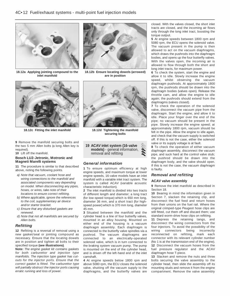
9 Remove the manifold securing bolts andthe two 5 mm Allen bolts (a long Allen key isrequired).10 Lift off the manifold.
Bosch LU2-Jetronic, Motronic andMagneti Marelli systems11 The procedure is similar to that describedabove, noting the following points.
a) Note that vacuum, coolant hose andwiring connections to the manifold andassociated components vary dependingon model. When disconnecting any pipes,hoses, or wires, take note of theirlocations to ensure correct refitting.
b) Where applicable, ignore the referencesto the coil, supplementary air deviceand/or starter bracket.
c) Ensure that any disturbed gaskets arerenewed.
d) Note that not all manifolds are secured byAllen bolts.
Refitting12 Refitting is a reversal of removal using anew gasket/seal or jointing compound asnecessary. Ensure that the locating dowelsare in position and tighten all bolts to theirspecified torque (see illustrations).Note: The engine gasket kit contains gasketsfor both carburettor and injection typemanifolds. The injection type gasket has cut-outs for the injector ports. Ensure that thecorrect gasket is fitted. The carburettor typewill partially obstruct the injector ports causingerratic running and loss of power.
19 ACAV inlet system (16-valvemodels) - general information,removal and refitting
3General information1 To ensure optimum efficiency at highengine speeds, and maximum torque at lowerengine speeds, 16-valve models have an inletmanifold with a variable inlet tract system. Thesystem is called ACAV (variable acousticcharacteristic induction).2 The inlet manifold is divided into two tractsof different length and diameter; a long tract(for low-speed torque) which is 650 mm long,diameter 36 mm, and a short tract (for high-speed power) which is 370 mm long, diameter45 mm.3 Situated between the manifold and thecylinder head is a line of four butterfly valves,mounted in an alloy housing. Mounted oneither end of the housing is a vacuumdiaphragm assembly. Each diaphragm isconnected to the butterfly valve spindles via apushrod. The vacuum diaphragms areconnected to an electrically-operatedsolenoid valve, which is in turn connected tothe braking system vacuum pump. The pumpis mounted on the end of the cylinder head,and is driven off the left-hand end of the inletcamshaft.4 At engine speeds below 1800 rpm andabove 5080 rpm, the ECU closes the solenoidvalve, shutting off the vacuum supply to thediaphragms, and the butterfly valves are
closed. With the valves closed, the short inlettracts are closed, and the incoming air flowsonly through the long inlet tract, boosting thetorque output.5 At engine speeds between 1800 rpm and5080 rpm, the ECU opens the solenoid valve.The vacuum present in the pump is thenallowed to act on the vacuum diaphragms,which draws the pushrods into the diaphragmbodies, and opens up the four butterfly valves.With the valves open, the incoming air isallowed to flow through both the short andlong inlet tracts, for maximum power.6 To check the system, start the engine andallow it to idle. Slowly increase the enginespeed, whilst observing the vacuumdiaphragm pushrods. At approximately 1800rpm, the pushrods should be drawn into thediaphragm bodies (valves open). Release thethrottle cam, and allow the engine to idleagain; the pushrods should extend from thediaphragms (valves closed).7 To check the operation of the solenoidvalve, disconnect the vacuum pipe from thediaphragm. Start the engine, and allow it toidle. Place your finger over the end of thepipe; no vacuum should be present in thepipe. Slowly increase the engine speed; atapproximately 1800 rpm, vacuum should befelt in the pipe. Allow the engine to idle again,and check that the vacuum supply is switchedoff. If this is not the case, either the solenoidvalve or its supply voltage is at fault.8 To check the operation of either vacuumdiaphragm assembly, disconnect the vacuumpipe, and suck hard at the control valve stub;the pushrod should be drawn into thediaphragm body, and the valve should open.If this is not the case, the vacuum diaphragmis faulty.
Removal and refitting
ACAV valve assembly9 Remove the inlet manifold as described inSection 18.10 Bearing in mind the information given inSection 7, slacken the retaining clip, anddisconnect the fuel feed and return hosesfrom their unions on the fuel rail. Where theoriginal crimped-type Peugeot hose clips arestill fitted, cut them off and discard them; usestandard worm-drive hose clips on refitting.11 Depress the retaining tangs, anddisconnect the wiring connectors from thefour injectors. To avoid the possibility of thewiring connectors being incorrectlyreconnected on refitting, mark eachconnector with its relevant cylinder number(No 1 is at the transmission end of the engine).12 Disconnect the vacuum hoses from thefuel pressure regulator and the ACAVdiaphragm hose T-piece.13 Slacken and remove the nuts and threebolts securing the valve assembly to thecylinder head, then slide the assembly off itsmounting studs and remove it from the enginecompartment. Remove the valve assembly
4C•12 Fuel/exhaust systems - multi-point fuel injection models
18.12a Applying jointing compound to theinlet manifold
18.12c Fitting the inlet manifold 18.12d Tightening the manifold securing bolts
18.12b Ensure locating dowels (arrowed)are in position
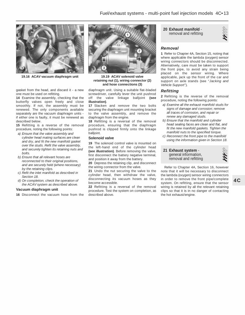
gasket from the head, and discard it - a newone must be used on refitting.14 Examine the assembly, checking that thebutterfly valves open freely and closesmoothly. If not, the assembly must berenewed. The only components availableseparately are the vacuum diaphragm units -if either one is faulty, it must be renewed asdescribed below.15 Refitting is a reverse of the removalprocedure, noting the following points:a) Ensure that the valve assembly and
cylinder head mating surfaces are cleanand dry, and fit the new manifold gasketover the studs. Refit the valve assembly,and securely tighten its retaining nuts andbolts.
b) Ensure that all relevant hoses arereconnected to their original positions,and are securely held (where necessary)by the retaining clips.
c) Refit the inlet manifold as described inSection 18.
d) On completion, check the operation ofthe ACAV system as described above.
Vacuum diaphragm unit16 Disconnect the vacuum hose from the
diaphragm unit. Using a suitable flat-bladedscrewdriver, carefully lever the unit pushrodoff the valve linkage balljoint (seeillustration).17 Slacken and remove the two boltssecuring the diaphragm unit mounting bracketto the valve assembly, and remove thediaphragm from the engine.18 Refitting is a reversal of the removalprocedure, ensuring that the diaphragmpushrod is clipped firmly onto the linkageballjoint.
Solenoid valve19 The solenoid control valve is mounted onthe left-hand end of the cylinder head (see illustration). Before removing the valve, first disconnect the battery negative terminal,and position it away from the battery.20 Depress the retaining clip, and disconnectthe wiring connector from the valve.21 Undo the nut securing the valve to thecylinder head, then withdraw the valve,disconnecting its vacuum hoses as theybecome accessible.22 Refitting is a reversal of the removalprocedure. Test the system on completion, asdescribed above.
20 Exhaust manifold - removal and refitting 2
Removal1 Refer to Chapter 4A, Section 15, noting thatwhere applicable the lambda (oxygen) sensorwiring connectors should be disconnected.Alternatively, care must be taken to supportthe front pipe, to avoid any strain beingplaced on the sensor wiring. Whereapplicable, jack up the front of the car andsupport on axle stands (see “Jacking andVehicle Support”).
Refitting2 Refitting is the reverse of the removalprocedure, noting the following points:a) Examine all the exhaust manifold studs for
signs of damage and corrosion; removeall traces of corrosion, and repair orrenew any damaged studs.
b) Ensure that the manifold and cylinderhead sealing faces are clean and flat, andfit the new manifold gaskets. Tighten themanifold nuts to the specified torque.
c) Reconnect the front pipe to the manifoldusing the information given in Section 18.
21 Exhaust system -general information, removal and refitting
3Refer to Chapter 4A, Section 16, however
note that it will be necessary to disconnectthe lambda (oxygen) sensor wiring connectorsin order to remove the front pipe/completesystem. On refitting, ensure that the sensorwiring is retained by all the relevant retainingclips so that it is in no danger of contactingthe hot exhaust/engine.
Fuel/exhaust systems - multi-point fuel injection models 4C•13
19.19 ACAV solenoid valve retaining nut (1), wiring connector (2)
and hose connections (3)
19.16 ACAV vacuum diaphragm unit
4C

4D
Chapter 4 Part D:Emission control systems
Catalytic converter - general information and precautions . . . . . . . . .3Emission control system check . . . . . . . . . . . . . . . . . . . .See Chapter 1
Emission control systems - testing and component renewal . . . . . . . .2General information . . . . . . . . . . . . . . . . . . . . . . . . . . . . . . . . . . . . . . .1
4D•1
Easy, suitable fornovice with littleexperience
Fairly easy, suitablefor beginner withsome experience
Fairly difficult,suitable for competentDIY mechanic
Difficult, suitable forexperienced DIYmechanic
Very difficult,suitable for expertDIY or professional
Degrees of difficulty
Contents
1 General information
1 All models have various built-in fuel systemfeatures which help to minimise emissions,and all models have at least the crankcaseemission-control system described below.Models with a catalytic converter are alsofitted with the exhaust and evaporativeemission control systems.2 Most models are able to run on 95 RONunleaded fuel, but the following early enginesmust use 97 RON leaded fuel. However it maybe possible to use unleaded fuel if the ignitionis retarded by 3° - check with your Peugeotdealer.a) TU3 (K1A)b) TU3A (K1G)c) XU92C (D2D)d) XU9J2 (D6A)e) XU9J4 (D6C)f) XU52C (B2A)
Crankcase emission control3 To reduce the emission of unburnedhydrocarbons from the crankcase into theatmosphere, the engine is sealed, and theblow-by gases and oil vapour are drawn fromthe crankcase, through a wire-mesh oilseparator, into the inlet tract, to be burned bythe engine during normal combustion.4 Under conditions of high manifolddepression (idling, deceleration) the gases willbe sucked positively out of the crankcase.Under conditions of low manifold depression(acceleration, full-throttle running) the gasesare forced out of the crankcase by the(relatively) higher crankcase pressure; if theengine is worn, the raised crankcase pressure(due to increased blow-by) will cause some ofthe flow to return under all manifoldconditions.
Exhaust emission control5 To minimise the amount of pollutants whichescape into the atmosphere, some models
are fitted with a catalytic converter in theexhaust system. On all models where acatalytic converter is fitted, the system is ofthe “closed-loop” type; a lambda (oxygen)sensor in the exhaust system provides the fuelinjection/ignition system ECU with constantfeedback, enabling the ECU to adjust themixture to provide the best possibleconditions for the converter to operate.6 The lambda sensor has a built-in heatingelement, controlled by the ECU through thelambda sensor relay, to quickly bring thesensor’s tip to an efficient operatingtemperature. The sensor’s tip is sensitive tooxygen, and sends the ECU a varying voltagedepending on the amount of oxygen in theexhaust gases. If the inlet air/fuel mixture istoo rich, the exhaust gases are low in oxygen,so the sensor sends a low-voltage signal. Thevoltage rises as the mixture weakens and theamount of oxygen in the exhaust gases rises.Peak conversion efficiency of all majorpollutants occurs if the inlet air/fuel mixture ismaintained at the chemically-correct ratio forthe complete combustion of petrol - 14.7parts (by weight) of air to 1 part of fuel (the
“stoichiometric” ratio). The sensor outputvoltage alters in a large step at this point, theECU using the signal change as a referencepoint, and correcting the inlet air/fuel mixtureaccordingly by altering the fuel injector pulsewidth (the length of time that the injector isopen).
Evaporative emission control7 To minimise the escape into theatmosphere of unburned hydrocarbons, anevaporative emissions control system is fittedto later models (see illustration). The fueltank filler cap is sealed, and a charcoalcanister, mounted underneath the front left-hand wing, collects the petrol vapoursgenerated in the tank when the car is parked.The canister stores them until they can becleared from the canister (under the control ofthe fuel injection/ignition system ECU) via thepurge solenoid valve. When the valve isopened, the fuel vapours pass into the inlettract, to be burned by the engine duringnormal combustion.8 To ensure that the engine runs correctlywhen it is cold and/or idling, the ECU does not
1.7 Evaporative emissions control system1 Fuel filler cap2 Charcoal canister3 Hose
4 Calibrated orifice5 Hose6 Solenoid valve
7 Coolant temperature sensor
10 Safety valve

open the purge control valve until the enginehas warmed up and is under load; the valvesolenoid is then modulated on and off, toallow the stored vapour to pass into the inlettract.
2 Emission control systems -testing and componentrenewal
2Crankcase emission control1 The components of this system require noroutine attention, other than to check that thehoses are clear and undamaged at regularintervals.
Evaporative emission control
Testing2 If the system is thought to be faulty,disconnect the hoses from the charcoalcanister and purge control valve, and checkthat they are clear by blowing through them. Ifthe purge control valve or charcoal canisterare thought to be faulty, they must berenewed.
Charcoal canister - renewal3 Jack up the front of the car and support onaxle stands (see “Jacking and VehicleSupport”). Remove the left-hand front wheel.4 Remove the left-hand front wheel arch linerwith reference to Chapter 11.5 Disconnect the hoses from the canister,noting their locations to ensure correctrefitting.6 Unscrew the clamp bolt, and lift thecanister from its clamp on the body panel.Alternatively, the complete clampbracket/canister assembly can be removed ifdesired. Store or dispose of the canistercarefully - it may contain fuel vapour.7 Refitting is a reversal of removal, but ensurethat the hoses are correctly reconnected asnoted before removal.
Purge valve(solenoid valve) - renewal8 The purge valve is located in the hoserunning from the carbon canister to thethrottle body/inlet manifold. The valve may bemounted on a bracket, or may simply beattached to the hoses, depending on model.
9 To remove the valve, first disconnect thebattery negative lead.10 Where applicable, unbolt the valvebracket, then disconnect the wiring plug.11 Disconnect the hoses from the valve,noting their locations to ensure correctrefitting, then withdraw the valve.12 Refitting is a reversal of removal, ensuringthat the hoses are correctly reconnected, asnoted before removal.
Exhaust emission control
Testing13 The performance of the catalyticconverter can be checked only by measuringthe idle mixture setting (exhaust gas COcontent) using an accurately calibratedexhaust gas analyser.14 If the CO level at the tailpipe is too high,the vehicle should be taken to a Peugeotdealer so that the complete fuel injection andignition systems, including the lambda sensor,can be thoroughly checked using the specialdiagnostic equipment.15 Once this has been done, any fault mustlie in the catalytic converter, which should berenewed as described below.
Catalytic converter - renewal16 Refer to Part A of this Chapter, for thecentre silencer.
Lambda sensor - renewalNote: The lambda sensor is fragile, and willnot work if it is dropped or knocked, if itspower supply is disrupted, or if any cleaningmaterials are used on it.17 According to model the Lambda sensor islocated either in the exhaust downpipe or inthe exhaust centre section.18 Where necessary, jack up the front of thecar and support on axle stands (see “Jackingand Vehicle Support”).19 Trace the wiring back from the lambdasensor to the connector and disconnect it.20 Unscrew the sensor and remove it alongwith its sealing washer.21 Refitting is a reversal of the removalprocedure, using a new sealing washer.Ensure that the sensor is securely tightened.Check that the wiring is correctly routed, andin no danger of contacting either the exhaustsystem or the engine.
3 Catalytic converter - generalinformation and precautions
The catalytic converter is a reliable andsimple device, which needs no maintenancein itself, but there are some facts of which anowner should be aware, if the converter is tofunction properly for its full service life.a) DO NOT use leaded petrol in a car
equipped with a catalytic converter - thelead will coat the precious metals,reducing their converting efficiency, andwill eventually destroy the converter.
b) Always keep the ignition and fuel systemswell-maintained in accordance with themanufacturer’s schedule.
c) If the engine develops a misfire, do notdrive the car at all (or at least as little aspossible) until the fault is cured.
d) DO NOT push- or tow-start the car - thiswill soak the catalytic converter inunburned fuel, causing it to overheatwhen the engine does start.
e) DO NOT switch off the ignition at highengine speeds.
f) DO NOT use fuel or engine oil additives -these may contain substances harmful tothe catalytic converter.
g) DO NOT continue to use the car if theengine burns oil to the extent of leaving avisible trail of blue smoke.
h) Remember that the catalytic converteroperates at very high temperatures. DONOT, therefore, park the car in dryundergrowth, or over long grass or pilesof dead leaves after a long run.
i) Remember that the catalytic converter isFRAGILE - do not strike it with toolsduring servicing work.
j) In some cases, a sulphurous smell (likethat of rotten eggs) may be noticed fromthe exhaust. This is common to manycatalytic converter-equipped cars, andonce the car has covered a few thousandmiles the problem should disappear.
k) The catalytic converter, used on a well-maintained and well-driven car, shouldlast for between 50 000 and 100 000miles - if the converter is no longereffective, it must be renewed.
4D•2 Emission control systems

5A
System type . . . . . . . . . . . . . . . . . . . . . . . . . . . . . . . . . . . . . . . . . . . 12-volt, negative earth
BatteryType . . . . . . . . . . . . . . . . . . . . . . . . . . . . . . . . . . . . . . . . . . . . . . . . . Fulmen, Delco or StecoCharge condition:
Poor . . . . . . . . . . . . . . . . . . . . . . . . . . . . . . . . . . . . . . . . . . . . . . . . . 12.5 voltsNormal . . . . . . . . . . . . . . . . . . . . . . . . . . . . . . . . . . . . . . . . . . . . . . . . 12.6 voltsGood . . . . . . . . . . . . . . . . . . . . . . . . . . . . . . . . . . . . . . . . . . . . . . . . . 12.7 volts
AlternatorType . . . . . . . . . . . . . . . . . . . . . . . . . . . . . . . . . . . . . . . . . . . . . . . . . Valeo, Bosch or Mitsubishi (depending on model)
Starter motorType . . . . . . . . . . . . . . . . . . . . . . . . . . . . . . . . . . . . . . . . . . . . . . . . . Valeo or Bosch (depending on model)
Chapter 5 Part A:Starting and charging systems
Alternator drivebelt - removal, refitting and tensioning . . . . . . . . . . . .6Alternator - removal and refitting . . . . . . . . . . . . . . . . . . . . . . . . . . . . .7Alternator - testing and overhaul . . . . . . . . . . . . . . . . . . . . . . . . . . . . .8Battery check . . . . . . . . . . . . . . . . . . . . . . . . . . . .See “Weekly checks”Battery - removal and refitting . . . . . . . . . . . . . . . . . . . . . . . . . . . . . . .4Battery - testing and charging . . . . . . . . . . . . . . . . . . . . . . . . . . . . . . .3Charging system - testing . . . . . . . . . . . . . . . . . . . . . . . . . . . . . . . . . .5Electrical fault-finding - general information . . . . . . . . . . . . . . . . . . . . .2Electrical system check . . . . . . . . . . . . . . . . . . . .See “Weekly checks”
General information and precautions . . . . . . . . . . . . . . . . . . . . . . . . . .1Ignition switch - removal and refitting . . . . . . . . . . . . . . . . . . . . . . . .12Oil level sensor - removal and refitting . . . . . . . . . . . . . . . . . . . . . . . .14Oil pressure warning light switch - removal and refitting . . . . . . . . . .13Oil temperature sensor - removal and refitting . . . . . . . . . . . . . . . . . .15Starter motor - removal and refitting . . . . . . . . . . . . . . . . . . . . . . . . .10Starter motor - testing and overhaul . . . . . . . . . . . . . . . . . . . . . . . . .11Starting system - testing . . . . . . . . . . . . . . . . . . . . . . . . . . . . . . . . . . .9
5A•1
Easy, suitable fornovice with littleexperience
Fairly easy, suitablefor beginner withsome experience
Fairly difficult,suitable for competentDIY mechanic
Difficult, suitable forexperienced DIYmechanic
Very difficult,suitable for expertDIY or professional
Degrees of difficulty
Specifications
Contents
1 General information andprecautions
General informationThe engine electrical system consists
mainly of the charging and starting systems.Because of their engine-related functions,these components are covered separatelyfrom the body electrical devices such as thelights, instruments, etc (which are covered inChapter 12). Refer to Part B for information onthe ignition system.
The electrical system is of the 12-voltnegative earth type.
The battery is of the low maintenance or“maintenance-free” (sealed for life) type and ischarged by the alternator, which is belt-drivenfrom the crankshaft pulley.
The starter motor is of the pre-engagedtype incorporating an integral solenoid. On
starting, the solenoid moves the drive pinioninto engagement with the flywheel ring gearbefore the starter motor is energised. Oncethe engine has started, a one-way clutchprevents the motor armature being driven bythe engine until the pinion disengages fromthe flywheel.
PrecautionsFurther details of the various systems are
given in the relevant Sections of this Chapter.While some repair procedures are given, theusual course of action is to renew thecomponent concerned. The owner whoseinterest extends beyond component renewalshould obtain a copy of the “AutomobileElectrical & Electronic Systems Manual”,available from the publishers of this manual.
It is necessary to take extra care whenworking on the electrical system to avoiddamage to semi-conductor devices (diodesand transistors), and to avoid the risk ofpersonal injury. In addition to the precautions
given in “Safety first!” at the beginning of thismanual, observe the following when workingon the system:
Always remove rings, watches, etc beforeworking on the electrical system. Even withthe battery disconnected, capacitivedischarge could occur if a component’s liveterminal is earthed through a metal object.This could cause a shock or nasty burn.
Do not reverse the battery connections.Components such as the alternator,electronic control units, or any othercomponents having semi-conductor circuitrycould be irreparably damaged.
If the engine is being started using jumpleads and a slave battery, connect thebatteries positive-to-positive and negative-to-negative (see “Roadside Repairs - jumpstarting”). This also applies when connectinga battery charger.
Never disconnect the battery terminals,the alternator, any electrical wiring or anytest instruments when the engine is running.

Do not allow the engine to turn thealternator when the alternator is notconnected.
Never “test” for alternator output by“flashing” the output lead to earth.
Never use an ohmmeter of the typeincorporating a hand-cranked generator forcircuit or continuity testing.
Always ensure that the battery negativelead is disconnected when working on theelectrical system.
Before using electric-arc weldingequipment on the car, disconnect thebattery, alternator and components such asthe fuel injection/ignition electronic controlunit to protect them from the risk of damage.
The radio/cassette unit fitted as standardequipment by Peugeot is equipped with abuilt-in security code to deter thieves. If thepower source to the unit is cut, the anti-theftsystem will activate. Even if the powersource is immediately reconnected, theradio/ cassette unit will not function until thecorrect security code has been entered.Therefore, if you do not know the correctsecurity code for the radio/cassette unit donot disconnect the battery negative terminalof the battery or remove the radio/cassetteunit from the vehicle. If a Peugeotradio/cassette unit is fitted, refer to“Radio/cassette unit anti-theft system -precaution” in the reference section at therear of this manual.
2 Electrical fault-finding -general information
Refer to Chapter 12.
3 Battery - testing and charging 1Standard and low maintenancebattery - testing1 If the vehicle covers a small annual mileage,it is worthwhile checking the specific gravityof the electrolyte every three months todetermine the state of charge of the battery.Use a hydrometer to make the check andcompare the results with the following table.The temperatures quoted in the table areambient (air) temperatures. Note that thespecific gravity readings assume anelectrolyte temperature of 15°C (60°F); forevery 10°C (50°F) below 15°C (60°F) subtract0.007. For every 10°C (50°F) above 15°C(60°F) add 0.007.
Above Below 25°C(77°F) 25°C(77°F)
Fully-charged 1.210 to 1.230 1.270 to 1.29070% charged 1.170 to 1.190 1.230 to 1.250Discharged 1.050 to 1.070 1.110 to 1.130
2 If the battery condition is suspect, first
check the specific gravity of electrolyte ineach cell. A variation of 0.040 or morebetween any cells indicates loss of electrolyteor deterioration of the internal plates.3 If the specific gravity variation is 0.040 ormore, the battery should be renewed. If thecell variation is satisfactory but the battery isdischarged, it should be charged asdescribed later in this Section.
Maintenance-free battery - testing4 In cases where a “sealed for life”maintenance-free battery is fitted, topping-upand testing of the electrolyte in each cell is notpossible. The condition of the battery cantherefore only be tested using a batterycondition indicator or a voltmeter.5 Certain models may be fitted with a “Delco”type maintenance-free battery, with a built-incharge condition indicator. The indicator islocated in the top of the battery casing, andindicates the condition of the battery from itscolour. If the indicator shows green, then thebattery is in a good state of charge. If theindicator turns darker, eventually to black,then the battery requires charging, asdescribed later in this Section. If the indicatorshows clear/yellow, then the electrolyte levelin the battery is too low to allow further use,and the battery should be renewed. Do notattempt to charge, load or jump start a batterywhen the indicator shows clear/yellow.6 If testing the battery using a voltmeter,connect the voltmeter across the battery andcompare the result with those given in theSpecifications under “charge condition”. Thetest is only accurate if the battery has notbeen subjected to any kind of charge for theprevious six hours. If this is not the case,switch on the headlights for 30 seconds, thenwait four to five minutes before testing thebattery after switching off the headlights. Allother electrical circuits must be switched off,so check that the doors and tailgate are fullyshut when making the test.7 If the voltage reading is less than 12.2 volts,then the battery is discharged, whilst areading of 12.2 to 12.4 volts indicates apartially discharged condition.8 If the battery is to be charged, remove itfrom the vehicle (Section 4) and charge it asdescribed later in this Section.
Standard and low maintenancebattery - chargingNote: The following is a guide only. Alwaysrefer to the manufacturer’s recommendations(often printed on a label attached to thebattery) before charging a battery.9 Charge the battery at a rate of 3.5 to 4amps and continue to charge the battery atthis rate unt il no further rise in specific gravityis noted over a four hour period.10 Alternatively, a trickle charger charging atthe rate of 1.5 amps can safely be usedovernight.11 Specially rapid “boost” chargers whichclaim to restore the battery in 1 to 2 hours are
not recommended, as they can cause damageto the battery plates through overheating.12 While charging the battery, note that thetemperature of the electrolyte should neverexceed 37.8°C (100°F).
Maintenance-free battery - chargingNote: The following is a guide only. Alwaysrefer to the manufacturer’s recommendations(often printed on a label attached to thebattery) before charging a battery.13 This battery type takes considerablylonger to fully recharge than the standardtype, the time taken being dependent on theextent of discharge, but it can take anythingup to three days.14 A constant voltage type charger isrequired, to be set, when connected, to 13.9to 14.9 volts with a charger current below 25amps. Using this method, the battery shouldbe usable within three hours, giving a voltagereading of 12.5 volts, but this is for a partiallydischarged battery and, as mentioned, fullcharging can take considerably longer.15 If the battery is to be charged from a fullydischarged state (condition reading less than12.2 volts), have it recharged by your Peugeotdealer or local automotive electrician, as thecharge rate is higher and constant supervisionduring charging is necessary.
4 Battery - removal and refitting 1Note: On models with a Peugeot anti-theftalarm system, disable the alarm beforedisconnecting the battery (see Chapter 12). Ifa Peugeot radio/cassette unit is fitted, refer to“Radio/cassette unit anti-theft system -precaution”.
Removal1 The battery is located at the right-hand rearcorner of the engine compartment.2 Disconnect the battery terminals, negativeterminal first, by unscrewing the wing nuts orclamp bolts. The negative terminal mustalways be disconnected first, andreconnected last (see illustration).
4.2 Battery positive terminal (A), negative terminal (B), clamp (C) and
fuel damper bracket (D)
5A•2 Starting and charging systems

3 Unscrew the nuts and remove the batteryclamp.4 Lift the battery from the battery tray. Notethe fuel damper bracket on fuel injectionmodels and the fuel pipes on carburettormodels.5 If necessary, release the wiring clips andunbolt the battery tray from the enginecompartment.
Refitting6 Refitting is a reversal of removal, but smearpetroleum jelly on the terminals whenreconnecting the leads, and always reconnectthe positive lead first, and the negative leadlast.
5 Charging system - testing 2Note: Refer to the warnings given in “Safetyfirst!” and in Section 1 of this Chapter beforestarting work.1 If the ignition warning light fails to illuminatewhen the ignition is switched on, first checkthe alternator wiring connections for security.If satisfactory, check that the warning lightbulb has not blown, and that the bulbholder issecure in its location in the instrument panel.If the light still fails to illuminate, check thecontinuity of the warning light feed wire fromthe alternator to the bulbholder. If all issatisfactory, the alternator is at fault, andshould be renewed or taken to an auto-electrician for testing and repair.2 If the ignition warning light illuminates whenthe engine is running, stop the engine andcheck that the drivebelt is correctly tensioned(see Chapter 1) and that the alternatorconnections are secure. If all is so farsatisfactory, have the alternator checked byan auto-electrician for testing and repair.3 If the alternator output is suspect eventhough the warning light functions correctly,the regulated voltage may be checked asfollows.4 Connect a voltmeter across the batteryterminals, and start the engine.5 Increase the engine speed until thevoltmeter reading remains steady; the reading
should be approximately 12 to 13 volts, andno more than 14 volts.6 Switch on as many electrical accessories(eg, the headlights, heated rear window andheater blower) as possible, and check that thealternator maintains the regulated voltage ataround 13 to 14 volts.7 If the regulated voltage is not as stated, thefault may be due to worn brushes, weak brushsprings, a faulty voltage regulator, a faultydiode, a severed phase winding, or worn ordamaged slip rings. The alternator should berenewed or taken to an auto-electrician fortesting and repair.
6 Alternator drivebelt -removal, refitting andtensioning
2Refer to the procedure given for the
auxiliary drivebelt in Chapter 1.
7 Alternator -removal and refitting 3
Removal1 Disconnect the battery negative lead.2 Disconnect the electrical connections onthe rear of the alternator (see illustration).3 Loosen the alternator mounting andadjustment strap bolts, push the alternatorinward and slip the drivebelt off the pulley.4 Remove the adjustment strap bolts andalternator pivot bolts and lift off the alternator(see illustrations).
Refitting5 Refit in reverse order, tensioning the belt asdescribed in Section 6.
8 Alternator -testing and overhaul 2
If the alternator is thought to be suspect, itshould be removed from the vehicle and takento an auto-electrician for testing. Most auto-
electricians will be able to supply and fitbrushes at a reasonable cost. However, checkon the cost of repairs before proceeding as itmay prove more economical to obtain a newor exchange motor.
9 Starting system - testing 2Note: Refer to the precautions given in“Safety first!” and in Section 1 of this Chapterbefore starting work.1 If the starter motor fails to operate when theignition key is turned to the appropriateposition, the following possible causes maybe to blame.a) The battery is faulty.b) The electrical connections between the
switch, solenoid, battery and startermotor are somewhere failing to pass thenecessary current from the batterythrough the starter to earth.
c) The solenoid is faulty.d) The starter motor is mechanically or
electrically defective.2 To check the battery, switch on theheadlights. If they dim after a few seconds,this indicates that the battery is discharged -recharge (see Section 3) or renew the battery.If the headlights glow brightly, operate theignition switch and observe the lights. If theydim, then this indicates that current isreaching the starter motor - therefore, the faultmust lie in the starter motor. If the lightscontinue to glow brightly (and no clickingsound can be heard from the starter motorsolenoid), this indicates that there is a fault inthe circuit or solenoid - refer to the followingparagraphs. If the starter motor turns slowlywhen operated, but the battery is in goodcondition, then this indicates that either thestarter motor is faulty, or there is considerableresistance somewhere in the circuit.3 If a fault in the circuit is suspected,disconnect the battery leads (including theearth connection to the body), the starter/solenoid wiring, and the engine/transmissionearth strap. Thoroughly clean the connections,reconnect the leads and wiring, then use avoltmeter or test light to check that full battery
Starting and charging systems 5A•3
7.4b . . . and lower bolt (arrowed)7.4a Slacken and remove the alternatorupper mounting bolt . . .
7.2 Connections on the rear of thealternator
5A

voltage is available at the battery positive leadconnection to the solenoid, and that the earthis sound. Smear petroleum jelly around thebattery terminals to prevent corrosion -corroded connections are among the mostfrequent causes of electrical system faults.4 If the battery and all connections are ingood condition, check the circuit bydisconnecting the wire from the solenoidblade terminal. Connect a voltmeter or testlight between the wire end and a good earth(such as the battery negative terminal), andcheck that the wire is live when the ignitionswitch is turned to the “start” position. If it is,then the circuit is sound - if not, the circuitwiring can be checked as described inChapter 12.5 The solenoid contacts can be checked byconnecting a voltmeter or test light betweenthe battery positive feed connection on thestarter side of the solenoid, and earth. Whenthe ignition switch is turned to the “start”position, there should be a reading or lightedbulb, as applicable. If there is no reading orlighted bulb, the solenoid is faulty, and shouldbe renewed.6 If the circuit and solenoid are provedsound, the fault must lie in the starter motor.In this event, it may be possible to have thestarter motor overhauled by a specialist, butcheck on the cost of spares beforeproceeding, as it may prove more economicalto obtain a new or exchange motor.
10 Starter motor -removal and refitting 3
Removal1 Disconnect the battery negative lead.2 Disconnect the electrical connections to thestarter motor (see illustration).3 Where necessary, loosen the bolts securingthe rear support bracket to the cylinder block(see illustration).4 Where necessary, unscrew the nutssecuring the rear of the starter motor to thesupport bracket.5 Remove the bolts securing the starter
motor to the gearbox housing (seeillustration). Note the location of any bracketsto ensure correct refitting.6 Unclip the crankcase breather hose fromthe bracket.7 Swing the bracket rearward, thenmanoeuvre the starter motor from the engine.
Refitting8 Refitting is a reversal of the removalprocedure.
11 Starter motor -testing and overhaul 2
If the starter motor is thought to be suspect,it should be removed from the vehicle andtaken to an auto-electrician for testing. Mostauto-electricians will be able to supply and fitbrushes at a reasonable cost. However, checkon the cost of repairs before proceeding as itmay prove more economical to obtain a newor exchange motor.
12 Ignition switch -removal and refitting 2
The ignition switch is integral with thesteering column lock, and can be removedwith reference to Chapter 10.
13 Oil pressure warning lightswitch - removal and refitting 2
Removal1 The switch is located at the front of thecylinder block, above the oil filter mounting.Note that on some models access to theswitch may be improved if the vehicle isjacked up and supported on axle stands sothat the switch can be reached fromunderneath (see “Jacking and VehicleSupport”).2 Disconnect the battery negative lead.
3 Remove the protective sleeve from thewiring plug (where applicable), thendisconnect the wiring from the switch.4 Unscrew the switch from the cylinder block,and recover the sealing washer. Be preparedfor oil spillage, and if the switch is to be leftremoved from the engine for any length oftime, plug the hole in the cylinder block.
Refitting5 Examine the sealing washer for signs ofdamage or deterioration and if necessaryrenew.6 Refit the switch, complete with washer, andtighten it securely. Reconnect the wiringconnector.7 Lower the vehicle to the ground then checkand, if necessary, top-up the engine oil asdescribed in Chapter 1.
14 Oil level sensor -removal and refitting 2
According to model the oil level sensor islocated on the front side of the cylinder blockjust to the right of the oil filter, or on the rearleft-hand side of the cylinder block.
The removal and refitting procedure is asdescribed for the oil pressure switch inSection 13. Access is most easily obtainedfrom underneath the vehicle (see illustration).
5A•4 Starting and charging systems
10.5 Unscrew the starter motor securing bolts (1). Note the location
of the bracket (2)
14.2 Removing the oil level sensor fromthe cylinder block
10.3 Starter support bracket bolts(arrowed) on an early model
10.2 Unscrew the two nuts (arrowed) anddisconnect the wiring from the rear of the
starter motor

15 Oil temperature sensor -removal and refitting 2
Removal1 The oil temperature sensor is screwed intothe sump (see illustration).2 To gain access to the sensor, firmly applythe handbrake then jack up the front of thevehicle and support it on axle stands (see“Jacking and Vehicle Support”).3 Drain the engine oil into a clean container
then refit the drain plug and tighten it to thespecified torque setting (see Chapter 1).4 Disconnect the wiring connector thenunscrew the sensor from the sump, andremove it from underneath the vehicle alongwith its sealing washer.
Refitting5 Examine the sealing washer for signs ofdamage or deterioration and if necessaryrenew.6 Refit the sensor, tightening it securely, andreconnect the wiring connector.7 Lower the vehicle to the ground and refillthe engine with oil as described in Chapter 1.
Starting and charging systems 5A•5
15.1 The oil temperature sensor isscrewed into the sump
5A

5B
System typeCarburettor, L3.1-Jetronic and LU2-Jetronic models . . . . . . . . . . . . . . Breakerless electronic ignition systemOther models except XU10J4 (16-valve) . . . . . . . . . . . . . . . . . . . . . . . . Integral ignition system controlled by engine management ECUXU10J4 (16-valve) models . . . . . . . . . . . . . . . . . . . . . . . . . . . . . . . . . . . Direct ignition system controlled by engine management ECU
Firing order . . . . . . . . . . . . . . . . . . . . . . . . . . . . . . . . . . . . . . . . . . . . 1-3-4-2 (number 1 cylinder at transmission end)
Ignition timingCarburettor models*:
TU3 engine . . . . . . . . . . . . . . . . . . . . . . . . . . . . . . . . . . . . . . . . . . . . . 8° BTDC at 750 rpmXU5 (B2A) and XU9 (D2H) engines . . . . . . . . . . . . . . . . . . . . . . . . . . . 10° BTDC at 750 rpm
Fuel injection models*:L3.1-Jetronic fuel injection models . . . . . . . . . . . . . . . . . . . . . . . . . . . 5° BTDC at 900 rpmLU2-Jetronic fuel injection models . . . . . . . . . . . . . . . . . . . . . . . . . . . 10° BTDC at 850 rpmAll other fuel injection models . . . . . . . . . . . . . . . . . . . . . . . . . . . . . . . ECU controlled (non-adjustable)
*Note: If unleaded fuel is used in the following engines, the ignition timing must be retarded by 3° - check with your Peugeot dealer.a) TU3 (K1A)b) TU3A (K1G)c) XU92C (D2D)d) XU9J2 (D6A)e) XU9J4 (D6C)f) XU52C (B2A)
Ignition HT coil resistances*:Primary windings . . . . . . . . . . . . . . . . . . . . . . . . . . . . . . . . . . . . . . . . 0.7 ohmsSecondary windings . . . . . . . . . . . . . . . . . . . . . . . . . . . . . . . . . . . . . . 6.6 K ohms
Impulse generator resistance . . . . . . . . . . . . . . . . . . . . . . . . . . . . . . . . . 300 ohms*The above specifications are approximate values and are accurate only when the coil is at 20°C. See text for further information
Torque wrench settings Nm lbf ftDistributor mounting nuts . . . . . . . . . . . . . . . . . . . . . . . . . . . . . . . . . . . . 8 5
Chapter 5 Part B:Ignition system
Distributor - removal and refitting . . . . . . . . . . . . . . . . . . . . . . . . . . . . .4Ignition HT coil(s) - removal, testing and refitting . . . . . . . . . . . . . . . . .3Ignition system - general information . . . . . . . . . . . . . . . . . . . . . . . . . .1Ignition system - testing . . . . . . . . . . . . . . . . . . . . . . . . . . . . . . . . . . . .2
Ignition system amplifier unit(s) - removal and refitting . . . . . . . . . . . .5Ignition system check . . . . . . . . . . . . . . . . . . . . . . . . . . .See Chapter 1Ignition timing - checking and adjustment . . . . . . . . . . . . . . . . . . . . . .6Spark plugs . . . . . . . . . . . . . . . . . . . . . . . . . . . . . . . . . . .See Chapter 1
5B•1
Easy, suitable fornovice with littleexperience
Fairly easy, suitablefor beginner withsome experience
Fairly difficult,suitable for competentDIY mechanic
Difficult, suitable forexperienced DIYmechanic
Very difficult,suitable for expertDIY or professional
Degrees of difficulty
Specifications
Contents
1 Ignition system - general information
Breakerless Electronic ignition system
All carburettor models, and models fittedwith the Bosch L3.1-Jetronic and Bosch LU2-Jetronic fuel injection systems are equipped
with a breakerless electronic ignition systemis used. The system comprises solely of theHT ignition coil and a distributor mounted onthe left-hand end of the cylinder head anddriven by the camshaft. On carburettormodels the coil is mounted on a bracketattached to the cylinder block, and on modelsfitted with L3.1 and LU2 systems it is mountedon the inlet manifold.
The distributor contains a reluctor mountedonto its shaft and a magnet and stator fixed to
its body. The ignition amplifier unit is alsomounted onto the side of the distributor body.The system operates as follows.
When the ignition is switched on but theengine is stationary the transistors in theamplifier unit prevent current flowing throughthe ignition system primary (LT) circuit.
As the crankshaft rotates, the reluctormoves through the magnetic field created bythe stator. When the reluctor teeth are inalignment with the stator projections a small
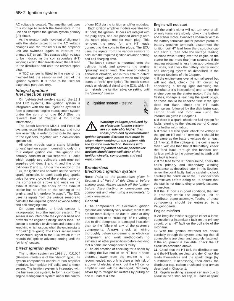
AC voltage is created. The amplifier unit usesthis voltage to switch the transistors in theunit and complete the ignition system primary(LT) circuit.
As the reluctor teeth move out of alignmentwith the stator projections the AC voltagechanges and the transistors in the amplifierunit are switched again to interrupt theprimary (LT) circuit. This causes a high voltageto be induced in the coil secondary (HT)windings which then travels down the HT leadto the distributor and onto the relevant sparkplug.
A TDC sensor is fitted to the rear of theflywheel but the sensor is not part of theignition system. It is there to be used fordiagnostic purposes only.
Integral ignition/fuel injection system
On fuel-injected models except the L3.1and LU2 systems, the ignition system isintegrated with the fuel injection system toform a combined engine management systemunder the control of one ECU (See therelevant Part of Chapter 4 for furtherinformation).
The Bosch Motronic ML4.1 and Fenix 1Bsystems retain the distributor cap and rotorarm assembly in order to distribute the sparkto the cylinders, together with a conventionalignition coil.
All other models use a static (distribu-torless) ignition system, consisting only of afour output ignition coil. The ignition coilactually consists of two separate HT coilswhich supply two cylinders each (one coilsupplies cylinders 1 and 4, and the othercylinders 2 and 3). Under the control of theECU, the ignition coil operates on the “wastedspark” principle, ie. each spark plug sparkstwice for every cycle of the engine, once onthe compression stroke and once on theexhaust stroke - the spark on the exhauststroke has no effect on the running of theengine, and is therefore “wasted”. The ECUuses its inputs from the various sensors tocalculate the required ignition advance settingand coil charging time.
On some models a knock sensor isincorporated into the ignition system. Thesensor is mounted onto the cylinder head andprevents the engine “pinking” under load. Thesensor is sensitive to vibration and detects theknocking which occurs when the engine startsto “pink” (pre-ignite). The knock sensor sendsan electrical signal to the ECU which in turnretards the ignition advance setting until the“pinking” ceases.
Direct ignition systemThe ignition system on 1998 cc XU10J4
(16-valve) models is of the “direct” type. Thesystem components consist of two amplifiermodules, four ignition HT coils, and a knocksensor. The ignition system is integrated withthe fuel injection system, to form a combinedengine management system under the control
of one ECU via the ignition amplifier modules.Each ignition amplifier module operates two
HT coils; the ignition HT coils are integral withthe plug caps, and are pushed directly ontothe spark plugs, one for each plug. Thisremoves the need for any HT leadsconnecting the coils to the plugs. The ECUuses the inputs from the various sensors tocalculate the required ignition advance settingand coil charging time.
The knock sensor is mounted onto thecylinder head, and prevents the engine“pinking” under load. The sensor detectsabnormal vibration, and is thus able to detectthe knocking which occurs when the enginestarts to “pink” (pre-ignite). The knock sensorsends an electrical signal to the ECU, which inturn retards the ignition advance setting untilthe “pinking” ceases.
2 Ignition system - testing 2
Breakerless Electronic ignition systemNote: Refer to the precautions given inSection 1 of Part A of this Chapter beforestarting work. Always switch off the ignitionbefore disconnecting or connecting anycomponent and when using a multi-meter tocheck resistances.
General1 The components of electronic ignitionsystems are normally very reliable; most faultsare far more likely to be due to loose or dirtyconnections or to “tracking” of HT voltagedue to dirt, dampness or damaged insulationthan to the failure of any of the system’scomponents. Always check all wiringthoroughly before condemning an electricalcomponent and work methodically toeliminate all other possibilities before decidingthat a particular component is faulty.2 The old practice of checking for a spark byholding the live end of an HT lead a shortdistance away from the engine is notrecommended; not only is there a high risk ofa powerful electric shock, but the HT coil oramplifier unit will be damaged. Similarly,never try to “diagnose” misfires by pulling offone HT lead at a time.
Engine will not start3 If the engine either will not turn over at all,or only turns very slowly, check the batteryand starter motor. Connect a voltmeter acrossthe battery terminals (meter positive probe tobattery positive terminal), disconnect theignition coil HT lead from the distributor capand earth it, then note the voltage readingobtained while turning over the engine on thestarter for (no more than) ten seconds. If thereading obtained is less than approximately9.5 volts, first check the battery, starter motorand charging system as described in therelevant Sections of this Chapter.4 If the engine turns over at normal speed butwill not start, check the HT circuit byconnecting a timing light (following themanufacturer’s instructions) and turning theengine over on the starter motor; if the lightflashes, voltage is reaching the spark plugs,so these should be checked first. If the lightdoes not flash, check the HT leadsthemselves followed by the distributor cap,carbon brush and rotor arm using theinformation given in Chapter 1.5 If there is a spark, check the fuel system forfaults referring to the relevant part of Chapter4 for further information.6 If there is still no spark, check the voltage atthe ignition HT coil “+” terminal; it should bethe same as the battery voltage (ie, at least11.7 volts). If the voltage at the coil is morethan 1 volt less than that at the battery, checkthe feed back through the fusebox andignition switch to the battery and its earth untilthe fault is found.7 If the feed to the HT coil is sound, check thecoil’s primary and secondary windingresistance as described later in this Section;renew the coil if faulty, but be careful to checkcarefully the condition of the LT connectionsthemselves before doing so, to ensure thatthe fault is not due to dirty or poorly-fastenedconnectors.8 If the HT coil is in good condition, the faultis probably within the amplifier unit ordistributor stator assembly. Testing of thesecomponents should be entrusted to aPeugeot dealer.
Engine misfires9 An irregular misfire suggests either a looseconnection or intermittent fault on the primarycircuit, or an HT fault on the coil side of therotor arm.10 With the ignition switched off, checkcarefully through the system ensuring that allconnections are clean and securely fastened.If the equipment is available, check the LTcircuit as described above.11 Check that the HT coil, the distributor capand the HT leads are clean and dry. Check theleads themselves and the spark plugs (bysubstitution, if necessary), then check thedistributor cap, carbon brush and rotor arm asdescribed in Chapter 1.12 Regular misfiring is almost certainly due toa fault in the distributor cap, HT leads or spark
5B•2 Ignition system
Warning: Voltages produced byan electronic ignition systemare considerably higher thanthose produced by conventional
ignition systems. Extreme care must betaken when working on the system withthe ignition switched on. Persons withsurgically-implanted cardiac pacemakerdevices should keep well clear of theignition circuits, components and testequipment.
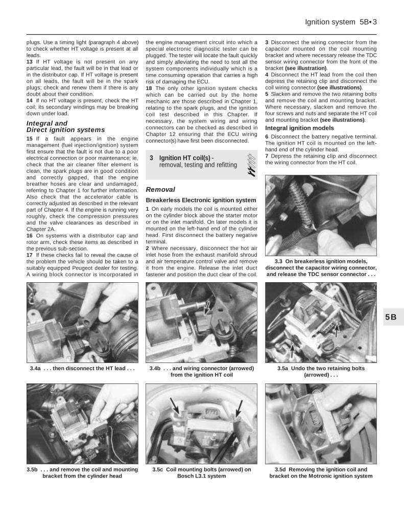
plugs. Use a timing light (paragraph 4 above)to check whether HT voltage is present at allleads.13 If HT voltage is not present on anyparticular lead, the fault will be in that lead orin the distributor cap. If HT voltage is presenton all leads, the fault will be in the sparkplugs; check and renew them if there is anydoubt about their condition.14 If no HT voltage is present, check the HTcoil; its secondary windings may be breakingdown under load.
Integral and Direct ignition systems15 If a fault appears in the enginemanagement (fuel injection/ignition) systemfirst ensure that the fault is not due to a poorelectrical connection or poor maintenance; ie,check that the air cleaner filter element isclean, the spark plugs are in good conditionand correctly gapped, that the enginebreather hoses are clear and undamaged,referring to Chapter 1 for further information.Also check that the accelerator cable iscorrectly adjusted as described in the relevantpart of Chapter 4. If the engine is running veryroughly, check the compression pressuresand the valve clearances as described inChapter 2A.16 On systems with a distributor cap androtor arm, check these items as described inthe previous sub-section.17 If these checks fail to reveal the cause ofthe problem the vehicle should be taken to asuitably equipped Peugeot dealer for testing.A wiring block connector is incorporated in
the engine management circuit into which aspecial electronic diagnostic tester can beplugged. The tester will locate the fault quicklyand simply alleviating the need to test all thesystem components individually which is atime consuming operation that carries a highrisk of damaging the ECU.18 The only other ignition system checkswhich can be carried out by the homemechanic are those described in Chapter 1,relating to the spark plugs, and the ignitioncoil test described in this Chapter. Ifnecessary, the system wiring and wiringconnectors can be checked as described inChapter 12 ensuring that the ECU wiringconnector(s) have first been disconnected.
3 Ignition HT coil(s) - removal, testing and refitting 2
Removal
Breakerless Electronic ignition system1 On early models the coil is mounted eitheron the cylinder block above the starter motoror on the inlet manifold. On later models it ismounted on the left-hand end of the cylinderhead. First disconnect the battery negativeterminal.2 Where necessary, disconnect the hot airinlet hose from the exhaust manifold shroudand air temperature control valve and removeit from the engine. Release the inlet ductfastener and position the duct clear of the coil.
3 Disconnect the wiring connector from thecapacitor mounted on the coil mountingbracket and where necessary release the TDCsensor wiring connector from the front of thebracket (see illustration).4 Disconnect the HT lead from the coil thendepress the retaining clip and disconnect thecoil wiring connector (see illustrations).5 Slacken and remove the two retaining boltsand remove the coil and mounting bracket.Where necessary, slacken and remove thefour screws and nuts and separate the HT coiland mounting bracket (see illustrations).
Integral ignition models6 Disconnect the battery negative terminal.The ignition HT coil is mounted on the left-hand end of the cylinder head.7 Depress the retaining clip and disconnectthe wiring connector from the HT coil.
Ignition system 5B•3
3.4b . . . and wiring connector (arrowed)from the ignition HT coil
3.5c Coil mounting bolts (arrowed) onBosch L3.1 system
3.5b . . . and remove the coil and mountingbracket from the cylinder head
3.5a Undo the two retaining bolts(arrowed) . . .
3.4a . . . then disconnect the HT lead . . .
3.3 On breakerless ignition models,disconnect the capacitor wiring connector,and release the TDC sensor connector . . .
5B
3.5d Removing the ignition coil andbracket on the Motronic ignition system
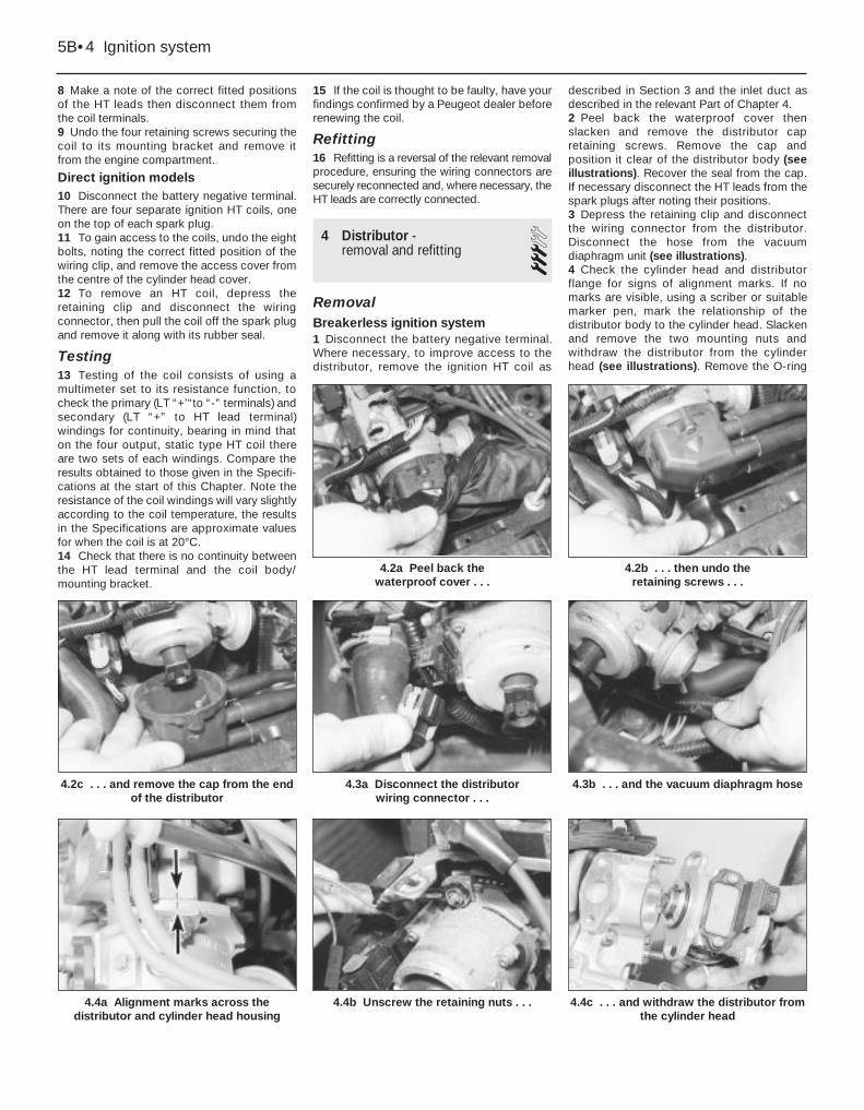
8 Make a note of the correct fitted positionsof the HT leads then disconnect them fromthe coil terminals.9 Undo the four retaining screws securing thecoil to its mounting bracket and remove itfrom the engine compartment.
Direct ignition models10 Disconnect the battery negative terminal.There are four separate ignition HT coils, oneon the top of each spark plug.11 To gain access to the coils, undo the eightbolts, noting the correct fitted position of thewiring clip, and remove the access cover fromthe centre of the cylinder head cover.12 To remove an HT coil, depress theretaining clip and disconnect the wiringconnector, then pull the coil off the spark plugand remove it along with its rubber seal.
Testing13 Testing of the coil consists of using amultimeter set to its resistance function, tocheck the primary (LT “+’“to “-” terminals) andsecondary (LT “+” to HT lead terminal)windings for continuity, bearing in mind thaton the four output, static type HT coil thereare two sets of each windings. Compare theresults obtained to those given in the Specifi-cations at the start of this Chapter. Note theresistance of the coil windings will vary slightlyaccording to the coil temperature, the resultsin the Specifications are approximate valuesfor when the coil is at 20°C.14 Check that there is no continuity betweenthe HT lead terminal and the coil body/mounting bracket.
15 If the coil is thought to be faulty, have yourfindings confirmed by a Peugeot dealer beforerenewing the coil.
Refitting16 Refitting is a reversal of the relevant removalprocedure, ensuring the wiring connectors aresecurely reconnected and, where necessary, theHT leads are correctly connected.
4 Distributor - removal and refitting 3
RemovalBreakerless ignition system1 Disconnect the battery negative terminal.Where necessary, to improve access to thedistributor, remove the ignition HT coil as
described in Section 3 and the inlet duct asdescribed in the relevant Part of Chapter 4.2 Peel back the waterproof cover thenslacken and remove the distributor capretaining screws. Remove the cap andposition it clear of the distributor body (seeillustrations). Recover the seal from the cap.If necessary disconnect the HT leads from thespark plugs after noting their positions.3 Depress the retaining clip and disconnectthe wiring connector from the distributor.Disconnect the hose from the vacuumdiaphragm unit (see illustrations).4 Check the cylinder head and distributorflange for signs of alignment marks. If nomarks are visible, using a scriber or suitablemarker pen, mark the relationship of thedistributor body to the cylinder head. Slackenand remove the two mounting nuts andwithdraw the distributor from the cylinderhead (see illustrations). Remove the O-ring
4.2a Peel back the waterproof cover . . .
4.2b . . . then undo the retaining screws . . .
5B•4 Ignition system
4.2c . . . and remove the cap from the endof the distributor
4.3b . . . and the vacuum diaphragm hose
4.4c . . . and withdraw the distributor fromthe cylinder head
4.4b Unscrew the retaining nuts . . .4.4a Alignment marks across thedistributor and cylinder head housing
4.3a Disconnect the distributor wiring connector . . .

from the end of the distributor body anddiscard it; a new one must be used onrefitting.
Integral ignition system withdistributor5 Disconnect the battery negative terminal. Ifnecessary, to improve access to thedistributor, remove the airflow meter asdescribed in Chapter 4.6 Peel back the waterproof cover, slackenand remove the distributor cap retainingscrews, then remove the cap and position itclear of the distributor body. Recover the sealfrom the cap. If necessary, disconnect the HTleads from the spark plugs after noting theirpositions - on 16-valve engines it will benecessary to remove the cover plate over thespark plugs.7 On 8-valve engines slacken and remove thetwo mounting bolts and washers, andwithdraw the distributor from the cylinderhead. Remove the O-ring from the end of thedistributor body, and discard it; a new onemust be used on refitting.8 On XU9J4 16-valve engines undo the threeTorx-headed screws securing the rotor to therotor drive flange and lift off the rotor, thenunscrew the screw from the centre of thedrive flange and withdraw the flange. Removethe plastic base plate from the end of thecylinder head (see illustrations).
Refitting
Breakerless ignition system9 Lubricate the new O-ring with a smear ofengine oil and fit it to the groove in the
distributor body. Examine the distributor capseal for wear or damage and renew ifnecessary.10 Align the distributor rotor shaft drivecoupling key with the slots in the camshaftend noting that the slots are offset to ensurethat the distributor can only be fitted in oneposition (see illustration). Carefully insert thedistributor into the cylinder head whilstrotating the rotor arm slightly to ensure thatthe coupling is correctly engaged. Refit thedistributor retaining nuts, tightening themlightly only.11 Ensure that the seal is correctly located inits groove then refit the cap assembly to thedistributor and tighten its retaining screwssecurely. Fold the waterproof cover back overthe distributor cap ensuring it is correctlylocated. Where necessary reconnect the HTleads to the spark plugs.12 Reconnect the vacuum hose to thediaphragm unit and the distributor wiringconnector. Where necessary, refit the ignitionHT coil as described in Section 3, and the inletduct as described in Chapter 4.13 Reconnect the battery negative terminal,then check and if necessary adjust the ignitiontiming as described in Section 6. Tighten thedistributor mounting nuts to the specifiedtorque.
Integral ignition system with distributor14 On XU9J4 16-valve engines refit theplastic base plate to the end of the cylinderhead, then refit the drive flange using lockingfluid on the threads of the drive flange screw.
Tighten the centre screw. Refit the rotor andtighten the Torx-headed screws.15 On 8-valve engines lubricate the new O-ring with a smear of engine oil and fit it to thegroove in the distributor body. Examine thedistributor cap seal for wear or damage andrenew if necessary. Align the distributor rotorshaft drive coupling key with the slots in thecamshaft end noting that the slots are offsetto ensure that the distributor can only be fittedin one position. Carefully insert the distributorinto the cylinder head whilst rotating the rotorarm slightly to ensure that the coupling iscorrectly engaged. Refit the distributorretaining nuts, tightening them securely.16 Ensure that the seal is correctly located inits groove then refit the cap assembly to thedistributor and tighten its retaining screwssecurely. Fold the waterproof cover back overthe distributor cap ensuring it is correctlylocated.17 Where necessary reconnect the HT leadsto the spark plugs (see illustration) and on 16-valve engines refit the cover plate.
5 Ignition system amplifierunit(s) - removal and refitting 2
Removal1 Disconnect the battery negative terminal.
Breakerless ignition system2 The amplifier unit is mounted onto the sideof the distributor body (see illustration). Toimprove access to the unit, disengage the hotair inlet hose from the control valve andmanifold shroud and remove it from thevehicle.3 Disconnect the wiring connector then undothe two retaining screws and remove theamplifier unit.
Integral ignition system4 The amplifier unit is located in the right-hand rear corner of the engine compartment.5 To remove the unit, disconnect the wiringconnector, undo the two retaining screws andremove the amplifier from its mountingbracket.
Ignition system 5B•5
4.10 Off-set drive slots on the camshaft
5.2 On breakerless ignition systems theamplifier unit is mounted on the side
of the distributor body
4.17 Distributor cap and HT leads on theXU9J4 16-valve model
4.8b Rotor drive flange4.8a On XU9J4 16-valve engines undo therotor screws and remove the rotor
5B
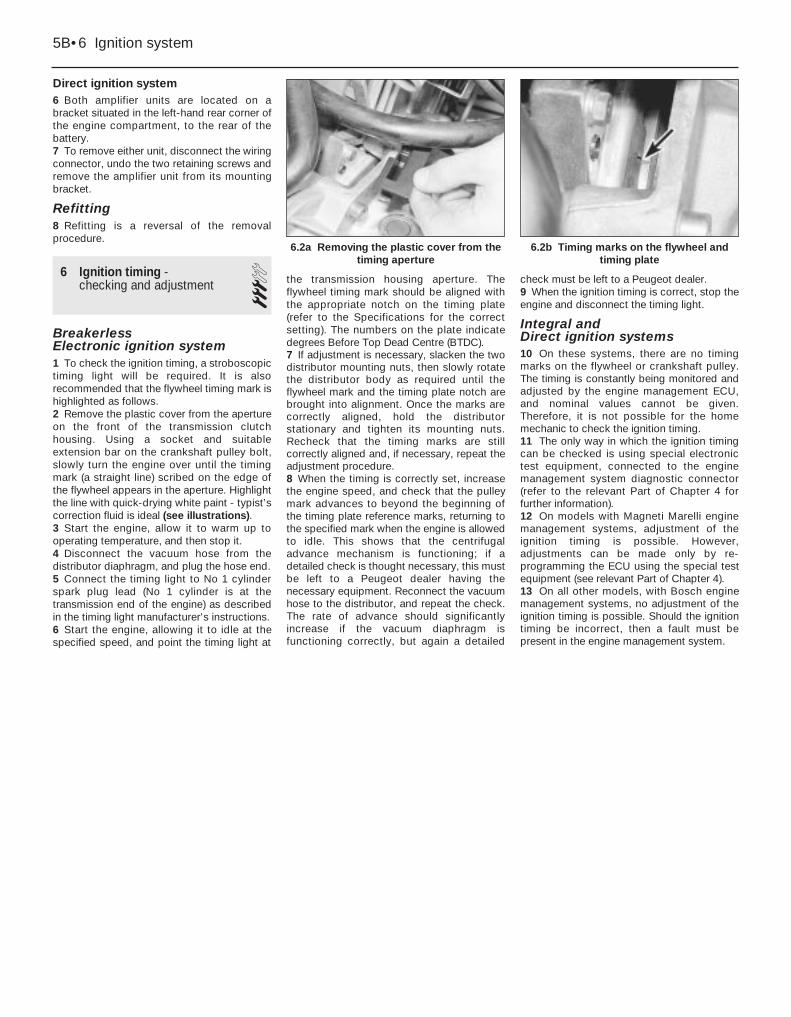
Direct ignition system6 Both amplifier units are located on abracket situated in the left-hand rear corner ofthe engine compartment, to the rear of thebattery.7 To remove either unit, disconnect the wiringconnector, undo the two retaining screws andremove the amplifier unit from its mountingbracket.
Refitting8 Refitting is a reversal of the removalprocedure.
6 Ignition timing - checking and adjustment 3
Breakerless Electronic ignition system1 To check the ignition timing, a stroboscopictiming light will be required. It is alsorecommended that the flywheel timing mark ishighlighted as follows.2 Remove the plastic cover from the apertureon the front of the transmission clutchhousing. Using a socket and suitableextension bar on the crankshaft pulley bolt,slowly turn the engine over until the timingmark (a straight line) scribed on the edge ofthe flywheel appears in the aperture. Highlightthe line with quick-drying white paint - typist’scorrection fluid is ideal (see illustrations).3 Start the engine, allow it to warm up tooperating temperature, and then stop it.4 Disconnect the vacuum hose from thedistributor diaphragm, and plug the hose end.5 Connect the timing light to No 1 cylinderspark plug lead (No 1 cylinder is at thetransmission end of the engine) as describedin the timing light manufacturer’s instructions.6 Start the engine, allowing it to idle at thespecified speed, and point the timing light at
the transmission housing aperture. Theflywheel timing mark should be aligned withthe appropriate notch on the timing plate(refer to the Specifications for the correctsetting). The numbers on the plate indicatedegrees Before Top Dead Centre (BTDC).7 If adjustment is necessary, slacken the twodistributor mounting nuts, then slowly rotatethe distributor body as required until theflywheel mark and the timing plate notch arebrought into alignment. Once the marks arecorrectly aligned, hold the distributorstationary and tighten its mounting nuts.Recheck that the timing marks are stillcorrectly aligned and, if necessary, repeat theadjustment procedure.8 When the timing is correctly set, increasethe engine speed, and check that the pulleymark advances to beyond the beginning ofthe timing plate reference marks, returning tothe specified mark when the engine is allowedto idle. This shows that the centrifugaladvance mechanism is functioning; if adetailed check is thought necessary, this mustbe left to a Peugeot dealer having thenecessary equipment. Reconnect the vacuumhose to the distributor, and repeat the check.The rate of advance should significantlyincrease if the vacuum diaphragm isfunctioning correctly, but again a detailed
check must be left to a Peugeot dealer.9 When the ignition timing is correct, stop theengine and disconnect the timing light.
Integral and Direct ignition systems10 On these systems, there are no timingmarks on the flywheel or crankshaft pulley.The timing is constantly being monitored andadjusted by the engine management ECU,and nominal values cannot be given.Therefore, it is not possible for the homemechanic to check the ignition timing.11 The only way in which the ignition timingcan be checked is using special electronictest equipment, connected to the enginemanagement system diagnostic connector(refer to the relevant Part of Chapter 4 forfurther information).12 On models with Magneti Marelli enginemanagement systems, adjustment of theignition timing is possible. However,adjustments can be made only by re-programming the ECU using the special testequipment (see relevant Part of Chapter 4).13 On all other models, with Bosch enginemanagement systems, no adjustment of theignition timing is possible. Should the ignitiontiming be incorrect, then a fault must bepresent in the engine management system.
5B•6 Ignition system
6.2a Removing the plastic cover from thetiming aperture
6.2b Timing marks on the flywheel andtiming plate
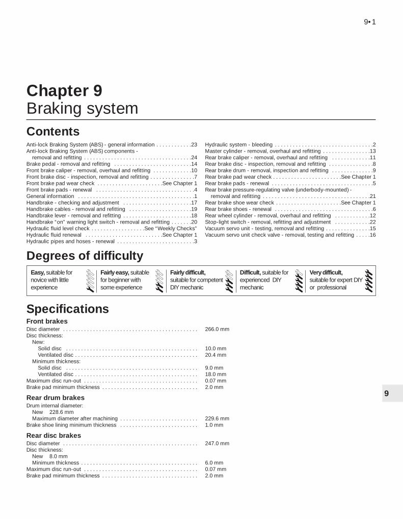
9
Front brakesDisc diameter . . . . . . . . . . . . . . . . . . . . . . . . . . . . . . . . . . . . . . . . . . . . . 266.0 mmDisc thickness:
New:Solid disc . . . . . . . . . . . . . . . . . . . . . . . . . . . . . . . . . . . . . . . . . . . . 10.0 mmVentilated disc . . . . . . . . . . . . . . . . . . . . . . . . . . . . . . . . . . . . . . . . . 20.4 mm
Minimum thickness:Solid disc . . . . . . . . . . . . . . . . . . . . . . . . . . . . . . . . . . . . . . . . . . . . 9.0 mmVentilated disc . . . . . . . . . . . . . . . . . . . . . . . . . . . . . . . . . . . . . . . . . 18.0 mm
Maximum disc run-out . . . . . . . . . . . . . . . . . . . . . . . . . . . . . . . . . . . . . . 0.07 mmBrake pad minimum thickness . . . . . . . . . . . . . . . . . . . . . . . . . . . . . . . . 2.0 mm
Rear drum brakesDrum internal diameter:
New 228.6 mmMaximum diameter after machining . . . . . . . . . . . . . . . . . . . . . . . . . . 229.6 mm
Brake shoe lining minimum thickness . . . . . . . . . . . . . . . . . . . . . . . . . . 1.0 mm
Rear disc brakesDisc diameter . . . . . . . . . . . . . . . . . . . . . . . . . . . . . . . . . . . . . . . . . . . . . 247.0 mmDisc thickness:
New 8.0 mmMinimum thickness . . . . . . . . . . . . . . . . . . . . . . . . . . . . . . . . . . . . . . . 6.0 mm
Maximum disc run-out . . . . . . . . . . . . . . . . . . . . . . . . . . . . . . . . . . . . . . 0.07 mmBrake pad minimum thickness . . . . . . . . . . . . . . . . . . . . . . . . . . . . . . . . 2.0 mm
Chapter 9Braking system
Anti-lock Braking System (ABS) - general information . . . . . . . . . . . .23Anti-lock Braking System (ABS) components -
removal and refitting . . . . . . . . . . . . . . . . . . . . . . . . . . . . . . . . . . . .24Brake pedal - removal and refitting . . . . . . . . . . . . . . . . . . . . . . . . . .14Front brake caliper - removal, overhaul and refitting . . . . . . . . . . . . .10Front brake disc - inspection, removal and refitting . . . . . . . . . . . . . . .7Front brake pad wear check . . . . . . . . . . . . . . . . . . . . . .See Chapter 1Front brake pads - renewal . . . . . . . . . . . . . . . . . . . . . . . . . . . . . . . . .4General information . . . . . . . . . . . . . . . . . . . . . . . . . . . . . . . . . . . . . . .1Handbrake - checking and adjustment . . . . . . . . . . . . . . . . . . . . . . .17Handbrake cables - removal and refitting . . . . . . . . . . . . . . . . . . . . .19Handbrake lever - removal and refitting . . . . . . . . . . . . . . . . . . . . . . .18Handbrake “on” warning light switch - removal and refitting . . . . . . .20Hydraulic fluid level check . . . . . . . . . . . . . . . . . .See “Weekly Checks”Hydraulic fluid renewal . . . . . . . . . . . . . . . . . . . . . . . . . .See Chapter 1Hydraulic pipes and hoses - renewal . . . . . . . . . . . . . . . . . . . . . . . . . .3
Hydraulic system - bleeding . . . . . . . . . . . . . . . . . . . . . . . . . . . . . . . . .2Master cylinder - removal, overhaul and refitting . . . . . . . . . . . . . . . .13Rear brake caliper - removal, overhaul and refitting . . . . . . . . . . . . .11Rear brake disc - inspection, removal and refitting . . . . . . . . . . . . . . .8Rear brake drum - removal, inspection and refitting . . . . . . . . . . . . . .9Rear brake pad wear check . . . . . . . . . . . . . . . . . . . . . . .See Chapter 1Rear brake pads - renewal . . . . . . . . . . . . . . . . . . . . . . . . . . . . . . . . . .5Rear brake pressure-regulating valve (underbody-mounted) -
removal and refitting . . . . . . . . . . . . . . . . . . . . . . . . . . . . . . . . . . . .21Rear brake shoe wear check . . . . . . . . . . . . . . . . . . . . . .See Chapter 1Rear brake shoes - renewal . . . . . . . . . . . . . . . . . . . . . . . . . . . . . . . . .6Rear wheel cylinder - removal, overhaul and refitting . . . . . . . . . . . .12Stop-light switch - removal, refitting and adjustment . . . . . . . . . . . .22Vacuum servo unit - testing, removal and refitting . . . . . . . . . . . . . . .15Vacuum servo unit check valve - removal, testing and refitting . . . . .16
9•1
Specifications
Contents
Easy, suitable fornovice with littleexperience
Fairly easy, suitablefor beginner withsome experience
Fairly difficult,suitable for competentDIY mechanic
Difficult, suitable forexperienced DIYmechanic
Very difficult,suitable for expert DIYor professional
Degrees of difficulty
54321

1 General information
The braking system is of the servo-assisted, dual-circuit hydraulic type. Thearrangement of the hydraulic system is suchthat each circuit operates one front and onerear brake from a tandem master cylinder.Under normal circumstances, both circuitsoperate in unison. However, in the event ofhydraulic failure in one circuit, full brakingforce will still be available at two wheels.
Some large-capacity engine models havedisc brakes all round as standard; othermodels are fitted with front disc brakes andrear drum brakes. ABS is fitted as standard tocertain models, and is offered as an option onmost other models (refer to Section 23 forfurther information on ABS operation).
The front disc brakes are actuated bysingle-piston sliding type calipers, whichensure that equal pressure is applied to eachdisc pad.
On models with rear drum brakes, the rearbrakes incorporate leading and trailing shoes,which are actuated by twin-piston wheelcylinders. On models not equipped with anunderbody-mounted rear brake pressureregulating valve, the wheel cylindersincorporate integral pressure-regulatingvalves, which control the hydraulic pressureapplied to the rear brakes. The regulatingvalves help to prevent rear wheel lock-upduring emergency braking. On some models,an underbody-mounted load-sensitive rearpressure-regulating valve is fitted. A self-adjust mechanism is incorporated, toautomatically compensate for brake shoewear. As the brake shoe linings wear, thefootbrake operation automatically operatesthe adjuster mechanism, which effectively
lengthens the shoe strut and repositions thebrake shoes, to remove the lining-to-drumclearance.
On models with rear disc brakes, thebrakes are actuated by single-piston slidingcalipers which incorporate mechanicalhandbrake mechanisms. A load-sensitivepressure-regulating valve is fitted to regulatethe hydraulic pressure applied to the rearbrakes. The regulating valve is similar to thatfitted to drum brake models with ABS, andhelps to prevent rear wheel lock-up duringemergency braking.
On all models, the handbrake provides anindependent mechanical means of rear brakeapplication.
Note: When servicing any part of thesystem, work carefully and methodically; alsoobserve scrupulous cleanliness whenoverhauling any part of the hydraulic system.Always renew components (in axle sets, whereapplicable) if in doubt about their condition,and use only genuine Peugeot replacementparts, or at least those of known good quality.Note the warnings given in “Safety first” and atrelevant points in this Chapter concerning thedangers of asbestos dust and hydraulic fluid.
2 Hydraulic system - bleeding 2
General1 The correct operation of any hydraulicsystem is only possible after removing all airfrom the components and circuit; this isachieved by bleeding the system.2 During the bleeding procedure, add onlyclean, unused hydraulic fluid of therecommended type; never re-use fluid thathas already been bled from the system.Ensure that sufficient fluid is available beforestarting work.3 If there is any possibility of incorrect fluidbeing already in the system, the brakecomponents and circuit must be flushedcompletely with uncontaminated, correctfluid, and new seals should be fitted to thevarious components.4 If hydraulic fluid has been lost from thesystem, or air has entered because of a leak,ensure that the fault is cured beforeproceeding further.
Torque wrench settings Nm lbf ftHydraulic pipe unions . . . . . . . . . . . . . . . . . . . . . . . . . . . . . . . . . . . . . . . 15 11Front brake caliper:
Guide pin bolts (Girling caliper)** . . . . . . . . . . . . . . . . . . . . . . . . . . . . 35 26Caliper mounting bolts (Bendix caliper):*^:
Early (solid) type hub carrier . . . . . . . . . . . . . . . . . . . . . . . . . . . . . . 120 89Later (hollow) type hub carrier . . . . . . . . . . . . . . . . . . . . . . . . . . . . 105 77
Caliper mounting bracket bolts (Girling caliper):*^Early (solid) type hub carrier . . . . . . . . . . . . . . . . . . . . . . . . . . . . . . 120 89Later (hollow) type hub carrier . . . . . . . . . . . . . . . . . . . . . . . . . . . . 105 77
Rear brake caliper:Guide pin bolts* . . . . . . . . . . . . . . . . . . . . . . . . . . . . . . . . . . . . . . . . . 35 26Caliper mounting bracket bolts* . . . . . . . . . . . . . . . . . . . . . . . . . . . . . 55 41
Master cylinder-to-servo unit nuts . . . . . . . . . . . . . . . . . . . . . . . . . . . . . 15 11Brake pedal pivot bolt nut . . . . . . . . . . . . . . . . . . . . . . . . . . . . . . . . . . . 20 15Vacuum servo unit securing nuts . . . . . . . . . . . . . . . . . . . . . . . . . . . . . . 20 15ABS wheel sensor securing bolts* . . . . . . . . . . . . . . . . . . . . . . . . . . . . . 10 7ABS wheel sensor adjuster bolt (Bendix “integral” ABS) . . . . . . . . . . . . 3 2ABS hydraulic modulator mounting nuts . . . . . . . . . . . . . . . . . . . . . . . . 20 15Roadwheel bolts . . . . . . . . . . . . . . . . . . . . . . . . . . . . . . . . . . . . . . . . . . . 85 63*Use thread-locking compound.**Use new bolts coated with thread-locking compound^Refer to note in Chapter 10, Section 2.
9•2 Braking system
Warning: Hydraulic fluid ispoisonous; wash offimmediately and thoroughly inthe case of skin contact, and
seek immediate medical advice if any fluidis swallowed or gets into the eyes. Certaintypes of hydraulic fluid are inflammable,and may ignite when allowed into contactwith hot components; when servicing anyhydraulic system, it is safest to assume
that the fluid is inflammable, and to takeprecautions against the risk of fire asthough it is petrol that is being handled.Hydraulic fluid is also an effective paintstripper, and will attack plastics; if any isspilt, it should be washed off immediately,using copious quantities of fresh water.Finally, it is hygroscopic (it absorbsmoisture from the air) - old fluid may becontaminated and unfit for further use.When topping-up or renewing the fluid,always use the recommended type, andensure that it comes from a freshly-opened sealed container.
Warning: Do not attempt tobleed any part of the hydraulicsystem on models equippedwith the Bendix “integral” ABS.
Special equipment is required, and thetask must be referred to a Peugeot dealer.

5 Park the vehicle on level ground, switch offthe engine and select first or reverse gear, thenchock the wheels and release the handbrake.6 Check that all pipes and hoses are secure,unions tight and bleed screws closed. Cleanany dirt from around the bleed screws.7 Unscrew the master cylinder reservoir cap,and top the master cylinder reservoir up to the“MAX” level line; refit the cap loosely, andremember to maintain the fluid level at leastabove the “MIN” level line throughout theprocedure, or there is a risk of further airentering the system.8 There are a number of one-man, do-it-yourselfbrake bleeding kits currently available from motor accessory shops. It is recommended thatone of these kits is used whenever possible, as they greatly simplify the bleeding operation,and also reduce the risk of expelled air and fluid being drawn back into the system. If such a kit is not available, the basic (two-man) method must be used, which is described indetail below.9 If a kit is to be used, prepare the vehicle asdescribed previously, and follow the kitmanufacturer’s instructions, as the proceduremay vary slightly according to the type beingused; generally, they are as outlined below inthe relevant sub-section.10 Whichever method is used, the samesequence must be followed to ensure theremoval of all air from the system.
Bleeding sequence
Conventional braking systema) Right-hand rear wheel.b) Left-hand front wheel.c) Left-hand rear wheel.d) Right-hand front wheel.
Bendix “additional” ABSNote: Before carrying out any bleeding,switch off the ignition, and disconnect the 3-pin brown wiring connector from the hydraulicmodulator assembly (see illustration).a) Rear brake furthest from master cylinder.b) Rear brake nearest master cylinder.c) Front brake furthest from master cylinder.
d) Front brake nearest master cylinder.e) Hydraulic modulator (see illustration).
Bosch “additional” ABSNote: Before carrying out any bleeding,switch off the ignition, and disconnect the 4-pin black wiring connector from the hydraulicmodulator assembly.a) Left-hand front wheel.b) Right-hand front wheel.c) Left-hand rear wheel.d) Right-hand rear wheel.
Note: If difficulty is experienced in bleedingthe hydraulic circuit on models with Bosch“additional” ABS, using the above sequence,try bleeding the complete system working inthe following order:a) Right-hand rear brake.b) Left-hand rear brake.c) Left-hand front brake.d) Right-hand front brake.
Bleeding - basic (two-man) method11 Collect a clean glass jar, a suitable lengthof plastic or rubber tubing which is a tight fitover the bleed screw, and a ring spanner to fitthe screw. The help of an assistant will also berequired.12 Remove the dust cap from the first screwin the sequence (see illustrations). Fit thespanner and tube to the screw, place the
other end of the tube in the jar, and pour insufficient fluid to cover the end of the tube.13 Ensure that the master cylinder reservoirfluid level is maintained at least above the“MIN” level line throughout the procedure.14 Have the assistant fully depress the brakepedal several times to build up pressure, thenmaintain it on the final downstroke.15 While pedal pressure is maintained,unscrew the bleed screw (approximately oneturn) and allow the compressed fluid and air toflow into the jar. The assistant should maintainpedal pressure, following it down to the floor ifnecessary, and should not release it untilinstructed to do so. When the flow stops,tighten the bleed screw again, have theassistant release the pedal slowly, andrecheck the reservoir fluid level.16 Repeat the steps given in paragraphs 14and 15 until the fluid emerging from the bleedscrew is free from air bubbles. If the mastercylinder has been drained and refilled, and airis being bled from the first screw in thesequence, allow approximately five secondsbetween cycles for the master cylinderpassages to refill.17 When no more air bubbles appear, tightenthe bleed screw securely, remove the tubeand spanner, and refit the dust cap. Do notovertighten the bleed screw.18 Repeat the procedure on the remainingscrews in the sequence, until all air isremoved from the system and the brake pedalfeels firm again.
Bleeding - using a one-way valve kit19 As their name implies, these kits consistof a length of tubing with a one-way valvefitted, to prevent expelled air and fluid beingdrawn back into the system; some kits includea translucent container, which can bepositioned so that the air bubbles can bemore easily seen flowing from the end of thetube.20 The kit is connected to the bleed screw,which is then opened. The user returns to thedriver’s seat, depresses the brake pedal witha smooth, steady stroke, and slowly releasesit; this is repeated until the expelled fluid isclear of air bubbles (see illustration).21 Note that these kits simplify work so
Braking system 9•3
2.12a Bleed nipple (arrowed) on front disc caliper
2.12b Bleed nipple (arrowed) on rearwheel cylinder
2.10b Bleed the hydraulic modulator usingthe bleed screws (1) first, and (2) second -
Bendix “additional” ABS
2.10a Disconnect the 3-pin brown wiringconnector before bleeding the Bendix
“additional” ABS
9

much that it is easy to forget the mastercylinder reservoir fluid level; ensure that this ismaintained at least above the “MIN” level lineat all times.
Bleeding - using a pressure-bleeding kit22 These kits are usually operated by thereservoir of pressurised air contained in thespare tyre. However, note that it will probablybe necessary to reduce the pressure to alower level than normal; refer to theinstructions supplied with the kit.23 By connecting a pressurised, fluid-filledcontainer to the master cylinder reservoir,bleeding can be carried out simply by openingeach screw in turn (in the specified sequence),and allowing the fluid to flow out until no moreair bubbles can be seen in the expelled fluid.24 This method has the advantage that thelarge reservoir of fluid provides an additionalsafeguard against air being drawn into thesystem during bleeding.25 Pressure-bleeding is particularly effectivewhen bleeding “difficult” systems, or whenbleeding the complete system at the time ofroutine fluid renewal.
All methods26 When bleeding is complete, and firmpedal feel is restored, wash off any spilt fluid,tighten the bleed screws securely, and refittheir dust caps.27 Check the hydraulic fluid level in themaster cylinder reservoir, and top-up ifnecessary (Chapter 1).28 Discard any hydraulic fluid that has beenbled from the system; it will not be fit for re-use.29 Check the feel of the brake pedal. If itfeels at all spongy, air must still be present inthe system, and further bleeding is required.Failure to bleed satisfactorily after areasonable repetition of the bleedingprocedure may be due to worn mastercylinder seals.30 On models with ABS, reconnect the wiringconnector to the hydraulic modulatorassembly.
3 Hydraulic pipes and hoses -renewal 4
Note: Before starting work, refer to the note atthe beginning of Section 2 concerning thedangers of hydraulic fluid.1 If any pipe or hose is to be renewed,minimise fluid loss by first removing themaster cylinder reservoir cap, then tighteningit down onto a piece of polythene to obtain anairtight seal. Alternatively, flexible hoses canbe sealed, if required, using a proprietarybrake hose clamp; metal brake pipe unionscan be plugged (if care is taken not to allowdirt into the system) or capped immediatelythey are disconnected. Place a wad of ragunder any union that is to be disconnected, tocatch any spilt fluid.2 If a flexible hose is to be disconnected,unscrew the brake pipe union nut beforeremoving the spring clip which secures thehose to its mounting bracket (seeillustration).3 To unscrew the union nuts, it is preferableto obtain a brake pipe spanner of the correctsize; these are available from most largemotor accessory shops. Failing this, a close-fitting open-ended spanner will be required,though if the nuts are tight or corroded, theirflats may be rounded-off if the spanner slips.In such a case, a self-locking wrench is oftenthe only way to unscrew a stubborn union, butit follows that the pipe and the damaged nutsmust be renewed on reassembly. Alwaysclean a union and surrounding area beforedisconnecting it. If disconnecting acomponent with more than one union, make acareful note of the connections beforedisturbing any of them.4 If a brake pipe is to be renewed, it can beobtained, cut to length and with the unionnuts and end flares in place, from Peugeotdealers. All that is then necessary is to bend itto shape, following the line of the original,before fitting it to the car. Alternatively, mostmotor accessory shops can make up brakepipes from kits, but this requires very carefulmeasurement of the original, to ensure thatthe replacement is of the correct length. Thesafest answer is usually to take the original tothe shop as a pattern.
5 On refitting, do not overtighten the unionnuts. It is not necessary to exercise bruteforce to obtain a sound joint.6 Ensure that the pipes and hoses arecorrectly routed, with no kinks, and that theyare secured in the clips or brackets provided.After fitting, remove the polythene from thereservoir, and bleed the hydraulic system asdescribed in Section 2. Wash off any spiltfluid, and check carefully for fluid leaks.
4 Front brake pads - renewal 2
1 Apply the handbrake, then jack up the frontof the vehicle and support it on axle stands(see “Jacking and Vehicle Support”). Removethe front roadwheels.2 Trace the brake pad wear sensor wiringback from the pads, and disconnect it fromthe wiring connector (see illustration). Notethe routing of the wiring, and free it from anyrelevant retaining clips.3 Push the piston into its bore by pulling thecaliper outwards.4 There are two different types of front brakecaliper fitted to the models covered in thismanual as follows.a) Models with solid front discs -
Bendix calipers.b) Models with ventilated front discs -
Girling calipers.
9•4 Braking system
4.2 Disconnecting the pad wear sensorwiring connector
3.2 Flexible hose-to-rigid pipe union atfront wheel arch
2.20 Using a one-man brake bleeding kiton a front caliper
Warning: Renew both sets offront brake pads at the sametime - never renew the pads ononly one wheel, as uneven
braking may result. Note that the dustcreated by wear of the pads may containasbestos, which is a health hazard. Neverblow it out with compressed air, and don’tinhale any of it. An approved filteringmask should be worn when working onthe brakes. DO NOT use petrol orpetroleum-based solvents to clean brakeparts; use brake cleaner or methylatedspirit only.

Bendix caliperNote: A new pad retaining plate spring clipshould be used on refitting.5 Using pliers, extract the small spring clipfrom the pad retaining plate, and then slidethe plate out of the caliper (see illustrations).6 Withdraw the pads from the caliper, thenmake a note of the correct fitted position ofeach anti-rattle spring, and remove the springfrom each pad (see illustration).7 First measure the thickness of each brakepad’s friction material (see illustration). Ifeither pad is worn at any point to the specifiedminimum thickness or less, all four pads mustbe renewed. Also, the pads should be renewedif any are fouled with oil or grease; as there isno satisfactory way of degreasing frictionmaterial, once contaminated. If any of thebrake pads are worn unevenly, or are fouledwith oil or grease, trace and rectify the causebefore reassembly. New brake pads and springkits are available from Peugeot dealers.8 If the brake pads are still serviceable,carefully clean them using a clean, fine wirebrush or similar, paying particular attention tothe sides and back of the metal backing. Cleanout the grooves in the friction material, andpick out any large embedded particles of dirtor debris. Carefully clean the pad locations inthe caliper body/mounting bracket.9 Prior to fitting the pads, check that theguide pins are free to slide easily in the caliperbody/mounting bracket, and check that therubber guide pin gaiters are undamaged.Brush the dust and dirt from the caliper andpiston, but do not inhale it, as it is injurious to
health. Inspect the dust seal around the pistonfor damage, and the piston for evidence offluid leaks, corrosion or damage. If attentionto any of these components is necessary,refer to Section 10.10 If new brake pads are to be fitted, thecaliper piston must be pushed back into thecylinder to make room for them. Either use aG-clamp or similar tool, or use suitable piecesof wood as levers. Provided that the mastercylinder reservoir has not been overfilled withhydraulic fluid, there should be no spillage,but keep a careful watch on the fluid levelwhile retracting the piston. If the fluid levelrises above the “MAX” level line at any time,the surplus should be siphoned off or ejectedvia a plastic tube connected to the bleedscrew (see Section 2). Note: Do not syphonthe fluid by mouth, as it is poisonous; use asyringe or an old poultry baster.11 Fit the anti-rattle springs to the pads, sothat when the pads are installed in the caliper,the spring end will be located at the oppositeend of the pad in relation to the pad retainingplate.12 Locate the pads in the caliper, ensuringthat the friction material of each pad is againstthe brake disc, and check that the anti-rattlespring ends are at the opposite end of the padto which the retaining plate is to be inserted.Note that if the pads are installed correctly,looking at the pads from the front of thevehicle, the innermost pad groove must behigher than the outer pad groove. Ensure thatthe pads are fitted correctly beforeproceeding (see illustrations).
13 Slide the retaining plate into place, andinstall the new small spring clip at its innerend. It may be necessary to file an entrychamfer on the edge of the retaining plate, toenable it to be fitted without difficulty.14 Reconnect the brake pad wear sensorwiring connectors, ensuring that the outerwire is correctly routed through the anti-rattlespring loops, and that both wires passthrough the loop of the bleed screw cap.15 Depress the brake pedal repeatedly, untilthe pads are pressed into firm contact withthe brake disc, and normal (non-assisted)pedal pressure is restored.16 Repeat the above procedure on theremaining front brake caliper.
Braking system 9•5
4.6 Withdrawing the outer brake pad -Bendix caliper
4.12b Correct fitting of brake pads -Bendix caliper
4.12a Correct location of the anti-rattlesprings on Bendix brake pads
4.7 Measuring brake pad friction materialthickness
4.5b . . . then slide the pad retaining platefrom the caliper - Bendix caliper
4.5a Extract the spring clip (arrowed) . . .
9
B GroovesD Pad retaining plate spring clipV Bleed screw

17 Refit the roadwheels, then lower thevehicle to the ground and tighten theroadwheel bolts to the specified torquesetting.18 Check the hydraulic fluid level asdescribed in “Weekly Checks”.
Girling caliperNote: A new lower guide pin bolt must beused on refitting.19 Where applicable, prise off the dust cover,then slacken and remove the lower caliperguide pin bolt, using a slim open-endedspanner to prevent the guide pin itself fromrotating (see illustration). Discard the guidepin bolt - a new bolt must be used on refitting.20 With the lower guide pin bolt removed,pivot the caliper upwards, away from thebrake pads and mounting bracket, taking carenot to strain the flexible brake hose (seeillustration).21 Withdraw the two brake pads from thecaliper mounting bracket, and examine themas described above in paragraphs 7 to 10.22 Apply a little brake grease to the rear ofthe pads, then Install the pads in the calipermounting bracket, ensuring that the frictionmaterial of each pad is against the brake disc(see illustration).23 Position the caliper over the pads, andpass the pad warning sensor wiring throughthe caliper aperture and underneath theretaining clip (see illustration). If the threadsof the new guide pin bolt are not already pre-
coated with locking compound, apply asuitable thread-locking compound to them.Pivot the caliper into position, then install theguide pin bolt, tightening to the specifiedtorque setting while retaining the guide pinwith an open-ended spanner. Whereapplicable, refit the dust cover to the guidepin.24 Reconnect the brake pad wear sensorwiring connector, ensuring that the wiring iscorrectly routed through the loop of thecaliper bleed screw cap.25 Depress the brake pedal repeatedly, untilthe pads are pressed into firm contact withthe brake disc, and normal (non-assisted)pedal pressure is restored.26 Repeat the procedure on the remainingfront brake caliper.27 Refit the roadwheels, then lower thevehicle to the ground and tighten theroadwheel bolts to the specified torquesetting.28 Check the hydraulic fluid level asdescribed in Chapter 1.
All calipers29 New pads will not give full brakingefficiency until they have bedded in. Beprepared for this, and avoid hard braking asfar as possible for the first hundred miles or soafter pad renewal.
5 Rear brake pads - renewal 2
Note: A new upper caliper guide pin bolt mustbe used on refitting.1 Chock the front wheels, then jack up therear of the vehicle and support securely onaxle stands (see “Jacking and VehicleSupport”). Remove the rear roadwheels.2 Disconnect the handbrake cable end fromthe operating lever on the caliper.3 Where applicable, prise off the dust cover,then slacken and remove the upper caliperguide pin bolt, using a slim open-endedspanner to prevent the guide pin itself fromrotating. Discard the guide pin bolt - a newbolt must be used on refitting.4 With the upper guide pin bolt removed,pivot the caliper downwards, away from thebrake pads and mounting bracket, taking carenot to strain the flexible brake hose.5 Withdraw the brake pads from the calipermounting bracket.6 First measure the thickness of each brakepad’s friction material. If either pad is worn atany point to the specified minimum thicknessor less, all four pads must be renewed. Also,the pads should be renewed if any are fouledwith oil or grease; there is no satisfactory wayof degreasing friction material, oncecontaminated. If any of the brake pads areworn unevenly, or are fouled with oil orgrease, trace and rectify the cause beforereassembly. New brake pads are availablefrom Peugeot dealers.7 If the brake pads are still serviceable,carefully clean them using a clean, fine wirebrush or similar, paying particular attention tothe sides and back of the metal backing. Pickout any large embedded particles of dirt ordebris from the friction material. Carefullyclean the pad locations in the caliperbody/mounting bracket.8 Prior to fitting the pads, check that theguide pins are free to slide easily in the caliperbody/mounting bracket, and check that therubber guide pin gaiters are undamaged.Brush the dust and dirt from the caliper andpiston, but do not inhale it, as it is injurious tohealth. Inspect the dust seal around the pistonfor damage, and the piston for evidence of
9•6 Braking system
4.19 Hold the pin guide pin with an open-ended spanner while slackening the guide
pin bolt - Girling caliper
4.22 Ensure that the brake pads are fittedthe correct way around, with friction
material facing the disc . . .
4.23 . . . then refit the caliper, feeding thepad wiring through the caliper aperture
4.20 Pivot the caliper upwards away fromthe brake pads - Girling caliper
Warning: Renew both sets ofrear brake pads at the sametime - never renew the pads ononly one wheel, as uneven
braking may result. Note that the dustcreated by wear of the pads may containasbestos, which is a health hazard. Neverblow it out with compressed air, and don’tinhale any of it. An approved filteringmask should be worn when working onthe brakes. DO NOT use petrol orpetroleum-based solvents to clean brakeparts; use brake cleaner or methylatedspirit only.
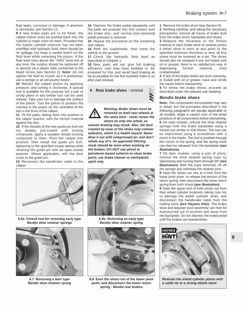
fluid leaks, corrosion or damage. If attentionis necessary, see Section 11.9 If new brake pads are to be fitted, thecaliper piston must be pushed back into thecylinder to make room for them. Provided thatthe master cylinder reservoir has not beenoverfilled with hydraulic fluid, there should beno spillage, but keep a careful watch on thefluid level while retracting the piston. If thefluid level rises above the “MAX” level line atany time, the surplus should be siphoned offor ejected via a plastic tube connected to thebleed screw (see Section 2). Note: Do notsyphon the fluid by mouth, as it is poisonous;use a syringe or an old poultry baster.10 Retract the caliper piston by applyingpressure, and turning it clockwise. A specialtool is available for this purpose but a pair ofcirclip pliers or any similar tool can be usedinstead. Take care not to damage the surfaceof the piston. Turn the piston to position thenotches in the piston on the centreline of theslot in the front of the caliper.11 Fit the pads, sliding them into position inthe caliper bracket, with the friction materialagainst the disc.12 If the threads of the new guide pin bolt arenot already pre-coated with lockingcompound, apply a suitable thread-lockingcompound to them. Pivot the caliper intoposition, then install the guide pin bolt,tightening to the specified torque setting whileretaining the guide pin with an open-endedspanner. Where applicable, refit the dustcover to the guide pin.13 Reconnect the handbrake cable to thecaliper.
14 Depress the brake pedal repeatedly untilthe pads are pressed into firm contact withthe brake disc, and normal (non-assisted)pedal pressure is restored.15 Repeat the procedure on the remainingrear caliper.16 Refit the roadwheels, then lower thevehicle to the ground.17 Check the hydraulic fluid level asdescribed in Chapter 1.18 New pads will not give full brakingefficiency until they have bedded in. Beprepared for this, and avoid hard braking asfar as possible for the first hundred miles or soafter pad renewal.
6 Rear brake shoes - renewal 3
1 Remove the brake drum (see Section 9).2 Working carefully, and taking the necessaryprecautions, remove all traces of brake dustfrom the brake drum, backplate and shoes.3 Measure the thickness of the frictionmaterial of each brake shoe at several points;if either shoe is worn at any point to thespecified minimum thickness or less, all fourshoes must be renewed as a set. The shoesshould also be renewed if any are fouled withoil or grease; there is no satisfactory way ofdegreasing friction material, oncecontaminated.4 If any of the brake shoes are worn unevenly,or fouled with oil or grease, trace and rectifythe cause before reassembly.5 To renew the brake shoes, proceed asdescribed under the relevant sub-heading.
Bendix brake shoesNote: The components encountered may varyin detail, but the principles described in thefollowing paragraphs are equally applicable toall models. Make a careful note of the fittedpositions of all components before dismantling.6 On early models, unhook the shoe retainersprings from the brake backplate using aforked tool similar to that shown. The tool canbe improvised using a screwdriver with anotch in the blade. The tool is pushed throughthe centre of the spring, and the spring hookcan then be released from the backplate (seeillustrations).7 On later models, using a pair of pliers,remove the shoe retainer spring cups bydepressing and turning them through 90º (seeillustration). With the cups removed, lift offthe springs and withdraw the retainer pins.8 Ease the shoes out one at a time from thelower pivot point, to release the tension of thereturn spring, then disconnect the lower returnspring from both shoes (see illustration).9 Ease the upper end of both shoes out fromtheir wheel cylinder locations, taking care notto damage the wheel cylinder seals, anddisconnect the handbrake cable from thetrailing shoe (see Haynes Hint). The brakeshoe and adjuster strut assembly can then bemanoeuvred out of position and away fromthe backplate. Do not depress the brake pedaluntil the brakes are reassembled.
Braking system 9•7
6.7 Removing a later type Bendix shoe retainer spring
6.8 Ease the shoes out of the lower pivotpoint, and disconnect the lower return
spring - Bendix rear brakes
9
6.6b Removing an early type Bendix shoe retainer spring
6.6a Forked tool for removing early typeBendix shoe retainer springs
Restrain the wheel cylinder piston witha cable-tie or a strong elastic band
Warning: Brake shoes must berenewed on both rear wheels atthe same time - never renew theshoes on only one wheel, as
uneven braking may result. Also, the dustcreated by wear of the shoes may containasbestos, which is a health hazard. Neverblow it out with compressed air, and don’tinhale any of it. An approved filteringmask should be worn when working onthe brakes. DO NOT use petrol orpetroleum-based solvents to clean brakeparts; use brake cleaner or methylatedspirit only.

10 With the shoe and adjuster strut assemblyon a bench, make a note of the correct fittedpositions of the springs and adjuster strut, touse as a guide on reassembly. Release thehandbrake lever stop-peg (if not alreadydone), then carefully detach the adjuster strutbolt retaining spring from the leading shoe.Disconnect the upper return spring, thendetach the leading shoe and return springfrom the trailing shoe and strut assembly.Unhook the spring securing the adjuster strutto the trailing shoe, and separate the two.11 If genuine Peugeot brake shoes are beinginstalled, it will be necessary to remove thehandbrake lever from the original trailing shoe,and install it on the new shoe. Secure thelever in position with a new retaining clip. Allreturn springs should be renewed, regardlessof their apparent condition; spring kits arealso available from Peugeot dealers.12 Withdraw the adjuster bolt from the strut,and carefully examine the assembly for signsof wear or damage. Pay particular attention tothe threads of the adjuster bolt and theknurled adjuster wheel, and renew ifnecessary. Note that left-hand and right-handstruts are not interchangeable - they aremarked “G” (gauche) and “D” (droit)respectively. Also note that the strut adjusterbolts are not interchangeable; the left-handstrut bolt has a left-handed thread, and theright-hand bolt a right-handed thread.13 Ensure that the components on the end ofthe strut are correctly positioned, then apply alittle high-melting-point grease to the threads
of the adjuster bolt (see illustration). Screwthe adjuster wheel onto the bolt until only asmall gap exists between the wheel and thehead of the bolt, then install the bolt in the strut.14 Fit the adjuster strut retaining spring tothe trailing shoe, ensuring that the shorterhook of the spring is engaged with the shoe.Attach the adjuster strut to the spring end,then ease the strut into position in its slot inthe trailing shoe.15 Engage the upper return spring with thetrailing shoe, then hook the leading shoe ontothe other end of the spring, and lever theleading shoe down until the adjuster bolt headis correctly located in its groove. Once thebolt is correctly located, hook its retainingspring into the slot on the leading shoe.16 Peel back the rubber protective caps, andcheck the wheel cylinder for fluid leaks orother damage; check that both cylinderpistons are free to move easily. Refer toSection 12, if necessary, for information onwheel cylinder renewal.17 Prior to installation, clean the backplate,and apply a smear of high-temperature brakegrease or anti-seize compound to all thosesurfaces of the backplate which bear on theshoes, particularly the wheel cylinder pistonsand lower pivot point (see illustration). Do notallow the lubricant to foul the friction material.18 Ensure that the handbrake lever stop-pegis correctly located against the edge of thetrailing shoe, and remove the elastic band orcable-tie (as applicable) fitted to the wheelcylinder.
19 Manoeuvre the shoe and strut assemblyinto position on the vehicle, and engage theupper end of both shoes with the wheelcylinder pistons. Attach the handbrake cableto the trailing shoe lever. Fit the lower returnspring to both shoes, and ease the shoes intoposition on the lower pivot point (seeillustrations).20 Tap the shoes to centralise them with thebackplate, then refit the shoe retainer pinsand springs, and secure them in position withthe spring cups.21 Using a screwdriver, turn the strutadjuster wheel to expand the shoes until thebrake drum just slides over the shoes.22 Refit the brake drum as described inSection 9.23 Repeat the above procedure on theremaining rear brake.24 Once both sets of rear shoes have beenrenewed, adjust the lining-to-drum clearanceby repeatedly depressing the brake pedal.Whilst depressing the pedal, have anassistant listen to the rear drums, to check
9•8 Braking system
6.13 Correct fitted position of later typeBendix adjuster strut components
6.19a Fitting the brake shoes - early type Bendix brakes
6.19d Later type Bendix shoe componentscorrectly assembled
6.19c Front view of early type Bendix shoeassembly correctly assembled - removed
from backplate for clarity
6.19b Rear view of early type Bendix shoeassembly correctly assembled - removed
from backplate for clarity
6.17 Apply high-melting-point grease tothe shoe contact points on the backplate
A Leading shoeB Trailing shoeC Lower pivot pointF Adjuster strut
mechanism
1 Upper return spring2 Lower return spring3 Retaining pin,
spring, spring cup4 Adjuster strut-to-
trailing shoe spring

that the adjuster strut is functioning correctly;if so, a clicking sound will be emitted by thestrut as the pedal is depressed.25 Check and, if necessary, adjust thehandbrake as described in Section 17.26 On completion, check the hydraulic fluidlevel as described in Chapter 1.
Girling brake shoes27 Make a note of the correct fitted positionsof the springs and adjuster strut, to use as aguide on reassembly (see illustration).28 Carefully unhook both the upper andlower return springs, and remove them fromthe brake shoes.29 Using a pair of pliers, remove the leadingshoe retainer spring cup by depressing it andturning through 90º. With the cup removed, liftoff the spring, then withdraw the retainer pinand remove the shoe from the backplate.Unhook the adjusting lever spring, andremove it from the leading shoe.30 Detach the adjuster strut, and remove itfrom the trailing shoe.31 Remove the trailing shoe retainer springcup, spring and pin as described above, thendetach the handbrake cable and remove theshoe from the vehicle. Do not depress thebrake pedal until the brakes are reassembled.
32 If genuine Peugeot brake shoes are beinginstalled, it will be necessary to remove theadjusting lever from the original leading shoe,and install it on the new shoe. All returnsprings should be renewed, regardless of theirapparent condition; spring kits are alsoavailable from Peugeot dealers.33 Withdraw the forked end from the adjusterstrut, and carefully examine the assembly forsigns of wear or damage. Pay particularattention to the threads and the knurledadjuster wheel, and renew if necessary. Notethat left-hand and right-hand struts are not
interchangeable; the left-hand fork has a left-handed thread, and the right-hand fork aright-handed thread.34 Peel back the rubber protective caps, andcheck the wheel cylinder for fluid leaks orother damage; check that both cylinderpistons are free to move easily. Refer toSection 12, if necessary, for information onwheel cylinder renewal.35 Prior to installation, clean the backplate,and apply a thin smear of high-temperaturebrake grease or anti-seize compound to allthose surfaces of the backplate which bear onthe shoes, particularly the wheel cylinderpistons and lower pivot point. Do not allowthe lubricant to foul the friction material.36 Ensure that the handbrake lever stop-pegis correctly located against the edge of thetrailing shoe, and remove the elastic band orcable-tie (as applicable) fitted to the wheelcylinder.37 Locate the upper end of the trailing shoein the wheel cylinder piston, then refit theretainer pin and spring, and secure it inposition with the spring cup. Connect thehandbrake cable to the lever.38 Screw in the adjuster wheel until theminimum strut length is obtained, then hookthe strut into position on the trailing shoe(note that the left and right-hand adjusters arenot interchangeable - see paragraph 33).Rotate the adjuster strut forked end, so thatthe cut-out of the fork will engage with theleading shoe adjusting lever once the shoe isinstalled (see illustration).39 Fit the spring to the leading shoeadjusting lever, so that the shorter hook of thespring engages with the lever.40 Slide the leading shoe assembly intoposition, ensuring that it is correctly engagedwith the adjuster strut fork, and that the forkcut-out is engaged with the adjusting lever.Ensure that the upper end of the shoe islocated in the wheel cylinder piston, thensecure the shoe in position with the retainerpin, spring and spring cup.41 Install the upper and lower return springs,then tap the shoes to centralise them with thebackplate.42 Using a screwdriver, turn the strutadjuster wheel to expand the shoes until thebrake drum just slides over the shoes.43 Refit the brake drum as described inSection 9.44 Repeat the above procedure on theremaining rear brake.45 Once both sets of rear shoes have beenrenewed, adjust the lining-to-drum clearance
by repeatedly depressing the brake pedal.Whilst depressing the pedal, have anassistant listen to the rear drums, to checkthat the adjuster strut is functioning correctly;if so, a clicking sound will be emitted by thestrut as the pedal is depressed.46 Check and, if necessary, adjust thehandbrake as described in Section 17.47 On completion, check the hydraulic fluidlevel as described in Chapter 1.
All shoes48 New shoes will not give full brakingefficiency until they have bedded in. Beprepared for this, and avoid hard braking asfar as possible for the first hundred miles or soafter shoe renewal.
7 Front brake disc - inspection,removal and refitting 2
Note: Before starting work, refer to the note atthe beginning of Section 4 concerning thedangers of asbestos dust.
InspectionNote: If either disc requires renewal, BOTHshould be renewed at the same time, toensure even and consistent braking. Newbrake pads should also be fitted.1 Apply the handbrake, then jack up the frontof the car and support it on axle stands (see“Jacking and Vehicle Support”). Remove theappropriate front roadwheel.2 Slowly rotate the brake disc so that the fullarea of both sides can be checked; removethe brake pads if better access is required tothe inboard surface. Light scoring is normal inthe area swept by the brake pads, but if heavyscoring or cracks are found, the disc must berenewed.3 It is normal to find a lip of rust and brakedust around the disc’s perimeter; this can bescraped off if required. If, however, a lip hasformed due to excessive wear of the brakepad swept area, then the disc’s thicknessmust be measured using a micrometer (seeillustration). Take measurements at severalplaces around the disc, at the inside andoutside of the pad swept area; if the disc has
Braking system 9•9
7.3 Using a micrometer to measure disc thickness
6.38 On Girling rear brake shoes, adjusterstrut fork cut-out (A) must engage withleading shoe adjusting lever on refitting
6.27 Correct fitted positions of Girling rearbrake components
Arrow indicates direction of wheel rotation
9
Wrap a strong elastic bandor a cable-tie around thewheel cylinder pistons toretain them.

worn at any point to the specified minimumthickness or less, the disc must be renewed.4 If the disc is thought to be warped, it can bechecked for run-out. Either use a dial gaugemounted on any convenient fixed point, whilethe disc is slowly rotated, or use feeler bladesto measure (at several points all around thedisc) the clearance between the disc and afixed point, such as the caliper mountingbracket (see illustration). If the measurementsobtained are at the specified maximum orbeyond, the disc is excessively warped, andmust be renewed; however, it is worthchecking first that the hub bearing is in goodcondition (Chapters 1 and/or 10). Also try theeffect of removing the disc and turning itthrough 180º, to reposition it on the hub; if therun-out is still excessive, the disc must berenewed.5 Check the disc for cracks, especiallyaround the wheel bolt holes, and any otherwear or damage, and renew if necessary.
Removal6 On models with Bendix calipers, removethe brake pads as described in Section 4.7 On models with Girling calipers, unscrewthe two bolts securing the caliper mountingbracket to the hub carrier (see illustration).Using a piece of wire or string, tie the caliperto the front suspension coil spring, to avoidplacing any strain on the fluid hose.8 Use chalk or paint to mark the relationshipof the disc to the hub, then remove thescrew(s) securing the brake disc to the hub,and remove the disc (see illustration). If it istight, lightly tap its rear face with a hide orplastic mallet.
Refitting9 Refitting is the reverse of the removalprocedure, noting the following points:a) Ensure that the mating surfaces of the
disc and hub are clean and flat.b) Align (if applicable) the marks made on
removal, and securely tighten the discretaining screws.
c) If a new disc has been fitted, use asuitable solvent to wipe any preservativecoating from the disc, before refitting thecaliper.
d) On models with Girling calipers, refit thecaliper as described in Section 10.
e) On models with Bendix calipers, refit thepads as described in Section 4.
f) Refit the roadwheel, then lower thevehicle to the ground and tighten theroadwheel bolts to the specified torque.On completion, repeatedly depress thebrake pedal until normal (non-assisted)pedal pressure returns.
8 Rear brake disc - inspection,removal and refitting 2
Note: Before starting work, refer to the note atthe beginning of Section 4 concerning thedangers of asbestos dust.
InspectionNote: If either disc requires renewal, BOTHshould be renewed at the same time, toensure even and consistent braking. Newbrake pads should be fitted also.1 Firmly chock the front wheels, then jack upthe rear of the car and support it on axlestands (see “Jacking and Vehicle Support”).Remove the appropriate rear roadwheel.2 Inspect the disc as described in Section 7.
Removal3 Remove the brake pads as described inSection 5.4 Use chalk or paint to mark the relationshipof the disc to the hub, then remove the screwsecuring the brake disc to the hub, andremove the disc. If it is tight, lightly tap its rearface with a hide or plastic mallet.
Refitting5 Refitting is the reverse of the removalprocedure, noting the following points:a) Ensure that the mating surfaces of the
disc and hub are clean and flat.b) Align (if applicable) the marks made on
removal, and securely tighten the discretaining screws.
c) If a new disc has been fitted, use asuitable solvent to wipe any preservativecoating from the disc, before refitting thecaliper.
d) Refit the brake pads as described inSection 5.
e) Refit the roadwheel, then lower thevehicle to the ground and tighten theroadwheel bolts to the specified torque.
9 Rear brake drum - removal,inspection and refitting 2
Note: Before starting work, refer to the note atthe beginning of Section 4 concerning thedangers of asbestos dust.
Removal1 Chock the front wheels, then jack up therear of the vehicle and support it on axlestands (see “Jacking and Vehicle Support”).Remove the appropriate rear roadwheel.2 Remove the drum retaining screw (seeillustration).3 It should now be possible to withdraw thebrake drum by hand. It may be difficult toremove the drum due to the brake shoesbinding on the inner circumference of thedrum. If the brake shoes are binding, proceedas follows.a) First check that the handbrake is fully
released, then referring to Section 17 forfurther information, fully slacken thehandbrake cable adjuster nut, to obtainmaximum free play in the cable.
b) Insert a screwdriver through the accesshole in the rear of the backplate (prise outthe blanking plug, where applicable), so
9•10 Braking system
7.8 Disc securing screws (arrowed)
9.2 Rear brake drum retaining screw (arrowed)
7.7 Removing a Girling caliper mounting bracket bolt
7.4 Checking disc run-out using a dial gauge

that it contacts the handbrake operatinglever on the trailing brake shoe. Push thelever until the stop-peg slips behind thebrake shoe web, allowing the brake shoesto retract fully (see illustrations). Thebrake drum can now be withdrawn.
InspectionNote: If either drum requires renewal, BOTHshould be renewed at the same time, toensure even and consistent braking. Newbrake shoes should also be fitted.4 Working carefully, remove all traces ofbrake dust from the drum, but avoid inhalingthe dust, as it is injurious to health.5 Clean the outside of the drum, and check itfor obvious signs of wear or damage, such ascracks around the roadwheel bolt holes;renew the drum if necessary.6 Examine carefully the inside of the drum.Light scoring of the friction surface is normal,but if heavy scoring is found, the drum mustbe renewed. It is usual to find a lip on thedrum’s inboard edge which consists of amixture of rust and brake dust; this should bescraped away, to leave a smooth surfacewhich can be polished with fine (120- to 150-grade) emery paper. If, however, the lip is dueto the friction surface being recessed byexcessive wear, then the drum must berenewed.7 If the drum is thought to be excessivelyworn, or oval, its internal diameter must bemeasured at several points using an internal
micrometer. Take measurements in pairs, thesecond at right-angles to the first, andcompare the two, to check for signs of ovality.Provided that it does not enlarge the drum tobeyond the specified maximum diameter, itmay be possible to have the drum refinishedby skimming or grinding; if this is not possible,the drums on both sides must be renewed.Note that if the drum is to be skimmed, BOTHdrums must be refinished, to maintain aconsistent internal diameter on both sides.
Refitting8 If a new brake drum is to be installed, use asuitable solvent to remove any preservativecoating that may have been applied to itsinterior. Note that it may also be necessary toshorten the adjuster strut length, by rotatingthe strut wheel, to allow the drum to pass overthe brake shoes.9 Ensure that the handbrake lever stop-peg iscorrectly repositioned against the edge of thebrake shoe web (see illustration), and ensurethat the mating faces of the hub and brakedrum are clean, then slide the brake drumonto the hub.10 Refit and tighten the drum retainingscrew.11 Depress the footbrake several times tooperate the self-adjusting mechanism.12 Repeat the above procedure on theremaining rear brake assembly (wherenecessary), then check and, if necessary,adjust the handbrake cable as described inSection 17.13 On completion, refit the roadwheel(s),then lower the vehicle to the ground andtighten the wheel bolts to the specifiedtorque.
10 Front brake caliper - removal,overhaul and refitting 3
Note: Before starting work, refer to the note atthe beginning of Section 2 concerning thedangers of hydraulic fluid, and to the warningat the beginning of Section 4 concerning thedangers of asbestos dust.
Bendix caliper
Removal1 Apply the handbrake, then jack up the frontof the vehicle and support it on axle stands(see “Jacking and Vehicle Support”). Removethe appropriate roadwheel.2 Minimise fluid loss by first removing themaster cylinder reservoir cap, and thentightening it down onto a piece of polythene,to obtain an airtight seal. Alternatively, use abrake hose clamp, a G-clamp or a similar toolto clamp the flexible hose (see illustration).3 Remove the brake pads as described inSection 4.4 Clean the area around the union, thenloosen the fluid hose union nut.5 Slacken the two bolts securing the caliperassembly to the hub carrier and remove themalong with the mounting plate, noting whichway around the plate is fitted. Lift the caliperassembly away from the brake disc, andunscrew it from the end of the fluid hose. Plugthe open ends of the caliper and hose toprevent dirt ingress and fluid loss.
Overhaul6 The caliper can be overhauled afterobtaining the relevant repair kit from aPeugeot dealer. Ensure that the correct repairkit is obtained for the caliper being worked on.Note the locations of all components toensure correct refitting, and lubricate the newseals using clean brake fluid. Follow theassembly instructions supplied with the repairkit (see illustration).
Braking system 9•11
9.9 Check that the handbrake lever stop-peg (arrowed) is against the shoe edge
E Handbrake operating lever stop-peg location
10.2 Using a clamp on the caliperhydraulic hose
9.3b Releasing the handbrake operating lever
9
9.3a Using a screwdriver inserted throughthe brake drum to release the handbrake
operating lever

Refitting7 Screw the caliper fully onto the flexible hoseunion, then position the caliper over the brakedisc.8 Clean the threads of the caliper mountingbolts, and apply a suitable locking compoundto them. Refit the bolts along with themounting plate, ensuring that the plate isfitted so that its bend curves away from thecaliper body. With the plate correctlypositioned, tighten the caliper bolts to thespecified torque.9 Securely tighten the brake hose union nut,then refit the brake pads as described inSection 4.10 Remove the brake hose clamp orpolythene, as applicable, and bleed thehydraulic system as described in Section 2.Note that, providing the precautionsdescribed were taken to minimise brake fluidloss, it should only be necessary to bleed therelevant front brake.11 Refit the roadwheel, then lower thevehicle to the ground and tighten theroadwheel bolts to the specified torque.
Girling caliper
RemovalNote: New guide pin bolts must be used onrefitting.12 Proceed as described in paragraphs 1 to 4.13 Where applicable, remove the dust cover,then slacken and remove the upper caliperguide pin bolt, using a slim open-endedspanner to prevent the guide pin itself fromrotating (see illustration). Discard the guidepin bolt - a new bolt must be used on refitting.Lift the caliper away from the disc, andunscrew it from the end of the fluid hose. Plugthe open ends of the caliper and hose toprevent dirt ingress and fluid loss.
Overhaul14 Proceed as described in paragraph 6 (seeillustration).
Refitting15 Screw the caliper body fully onto theflexible hose union.16 If the threads of the new guide pin boltsare not already pre-coated with lockingcompound, apply a suitable lockingcompound to them.
9•12 Braking system
10.13 Removing a Girling caliper upperguide pin bolt
1 Guide bolt2 Caliper body3 Pad retaining plate kit4 Bleed screw5 Mounting plate6 Guide pin assembly7 Repair kit
10.6 Components of Bendix front caliper
10.14 Components of Girlingfront caliper
1 Mounting bracket bolt2 Bleed screw3 Caliper body4 Mounting bracket5 Guide pin assembly6 Repair kit
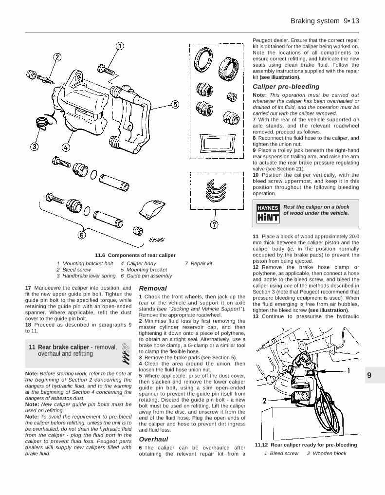
17 Manoeuvre the caliper into position, andfit the new upper guide pin bolt. Tighten theguide pin bolt to the specified torque, whileretaining the guide pin with an open-endedspanner. Where applicable, refit the dustcover to the guide pin bolt.18 Proceed as described in paragraphs 9 to 11.
11 Rear brake caliper - removal,overhaul and refitting 3
Note: Before starting work, refer to the note atthe beginning of Section 2 concerning thedangers of hydraulic fluid, and to the warningat the beginning of Section 4 concerning thedangers of asbestos dust.Note: New caliper guide pin bolts must beused on refitting.Note: To avoid the requirement to pre-bleedthe caliper before refitting, unless the unit is tobe overhauled, do not drain the hydraulic fluidfrom the caliper - plug the fluid port in thecaliper to prevent fluid loss. Peugeot partsdealers will supply new calipers filled withbrake fluid.
Removal1 Chock the front wheels, then jack up therear of the vehicle and support it on axlestands (see “Jacking and Vehicle Support”).Remove the appropriate roadwheel.2 Minimise fluid loss by first removing themaster cylinder reservoir cap, and thentightening it down onto a piece of polythene,to obtain an airtight seal. Alternatively, use abrake hose clamp, a G-clamp or a similar toolto clamp the flexible hose.3 Remove the brake pads (see Section 5).4 Clean the area around the union, thenloosen the fluid hose union nut.5 Where applicable, prise off the dust cover,then slacken and remove the lower caliperguide pin bolt, using a slim open-endedspanner to prevent the guide pin itself fromrotating. Discard the guide pin bolt - a newbolt must be used on refitting. Lift the caliperaway from the disc, and unscrew it from theend of the fluid hose. Plug the open ends ofthe caliper and hose to prevent dirt ingressand fluid loss.
Overhaul6 The caliper can be overhauled afterobtaining the relevant repair kit from a
Peugeot dealer. Ensure that the correct repairkit is obtained for the caliper being worked on.Note the locations of all components toensure correct refitting, and lubricate the newseals using clean brake fluid. Follow theassembly instructions supplied with the repairkit (see illustration).
Caliper pre-bleedingNote: This operation must be carried outwhenever the caliper has been overhauled ordrained of its fluid, and the operation must becarried out with the caliper removed.7 With the rear of the vehicle supported onaxle stands, and the relevant roadwheelremoved, proceed as follows.8 Reconnect the fluid hose to the caliper, andtighten the union nut.9 Place a trolley jack beneath the right-handrear suspension trailing arm, and raise the armto actuate the rear brake pressure regulatingvalve (see Section 21).10 Position the caliper vertically, with thebleed screw uppermost, and keep it in thisposition throughout the following bleedingoperation.
11 Place a block of wood approximately 20.0mm thick between the caliper piston and thecaliper body (ie, in the position normallyoccupied by the brake pads) to prevent thepiston from being ejected.12 Remove the brake hose clamp orpolythene, as applicable, then connect a hoseand bottle to the bleed screw, and bleed thecaliper using one of the methods described inSection 3 (note that Peugeot recommend thatpressure bleeding equipment is used). Whenthe fluid emerging is free from air bubbles,tighten the bleed screw (see illustration).13 Continue to pressurise the hydraulic
Braking system 9•13
11.12 Rear caliper ready for pre-bleeding
1 Bleed screw 2 Wooden block
1 Mounting bracket bolt2 Bleed screw3 Handbrake lever spring
4 Caliper body5 Mounting bracket6 Guide pin assembly
7 Repair kit
11.6 Components of rear caliper
9
Rest the caliper on a blockof wood under the vehicle.

system (eg, by “pumping” the brake pedal)until the caliper piston contacts the block ofwood.14 Open the caliper bleed screw, and removethe block of wood from the caliper.15 Push the caliper piston fully into thecaliper bore. Retract the caliper piston byapplying pressure, and turning it clockwise. Aspecial tool is available for this purpose but apair of circlip pliers or any similar tool can beused instead. Take care not to damage thesurface of the piston. Turn the piston toposition the notches in the piston on thecentreline of the slot in the front of the caliper.16 Tighten the bleed screw.17 Refit the block of wood to the caliper,then repeat the procedure described inparagraphs 12 to 17 inclusive.18 On completion, ensure that the bleedscrew is tightened, then disconnect the bleedhose.19 Lower the trailing arm and remove thetrolley jack, then refit the caliper as follows.
RefittingNote: Provided that the caliper has not beendrained of its fluid, the unit can be refitted asfollows. If the caliper has been overhauled ordrained for any reason, the pre-bleedingprocedure described in the precedingparagraphs must be carried out beforerefitting.20 Screw the caliper body fully onto theflexible hose union (if not already done).21 If the threads of the new guide pin boltsare not already pre-coated with lockingcompound, apply a suitable lockingcompound to them.22 Manoeuvre the caliper into position, andfit the new lower guide pin bolt. Tighten theguide pin bolt to the specified torque, whileretaining the guide pin with an open-endedspanner. Where applicable, refit the dustcover to the guide pin bolt.23 Securely tighten the brake hose union nut(if not already done), then refit the brake padsas described in Section 5.24 Remove the brake hose clamp orpolythene, as applicable, and bleed thehydraulic system as described in Section 2 (ifnot already done). Note that, providing theprecautions described were taken to minimisebrake fluid loss, it should only be necessary tobleed the relevant rear brake.25 Refit the roadwheel, then lower thevehicle to the ground and tighten theroadwheel bolts to the specified torque.
12 Rear wheel cylinder -removal, overhaul and refitting 3
Note: Before starting work, refer to the note atthe beginning of Section 2 concerning thedangers of hydraulic fluid, and to the warningat the beginning of Section 4 concerning thedangers of asbestos dust.
Removal1 Remove the brake drum (see Section 9).2 Using pliers, carefully unhook the upperbrake shoe return spring, and remove it fromboth brake shoes. Pull the upper ends of theshoes away from the wheel cylinder todisengage them from the pistons.3 Minimise fluid loss by first removing themaster cylinder reservoir cap, and thentightening it down onto a piece of polythene,to obtain an airtight seal. Alternatively, use abrake hose clamp, a G-clamp or a similar toolto clamp the flexible hose at the nearestconvenient point to the wheel cylinder.4 Wipe away all traces of dirt around thebrake pipe union at the rear of the wheelcylinder, and unscrew the union nut (seeillustration). Carefully ease the pipe out of thewheel cylinder, and plug or tape over its endto prevent dirt entry. Wipe off any spilt fluidimmediately.5 Unscrew the two wheel cylinder retainingbolts from the rear of the backplate, andremove the cylinder, taking great care not toallow surplus hydraulic fluid to contaminatethe brake shoe linings.
Overhaul
Models without underbody-mountedrear brake pressure-regulating valve(see Section 21)6 It is not possible to overhaul the cylinder,since no components are available separately.If faulty, the complete wheel cylinderassembly must be renewed.
Models with underbody-mounted rearbrake pressure-regulating valve (seeSection 21)7 The wheel cylinder can be overhauled afterobtaining the relevant repair kit from aPeugeot dealer. Ensure that the correct repairkit is obtained for the wheel cylinder beingworked on. Note the locations of allcomponents to ensure correct refitting, andlubricate the new seals using clean brakefluid. Follow the assembly instructionssupplied with the repair kit (see illustrations).
Refitting8 Ensure that the backplate and wheelcylinder mating surfaces are clean, then
spread the brake shoes and manoeuvre thewheel cylinder into position.9 Engage the brake pipe, and screw in theunion nut two or three turns to ensure that thethread has started.10 Insert the two wheel cylinder retainingbolts, and tighten them securely. Now fullytighten the brake pipe union nut.11 Remove the clamp from the flexible brakehose, or the polythene from the mastercylinder reservoir (as applicable).12 Ensure that the brake shoes are correctlylocated in the cylinder pistons, then carefullyrefit the brake shoe upper return spring, usinga screwdriver to stretch the spring intoposition.13 Refit the brake drum (see Section 9).14 Bleed the brake hydraulic system (seeSection 2). Providing precautions were takento minimise loss of fluid, it should only benecessary to bleed the relevant rear brake.
9•14 Braking system
12.4 Brake pipe union (A) and rear wheelcylinder retaining bolts (B)
12.7b Bendix rear wheel cylindercomponents - models with underbody-
mounted brake pressure-regulating valve1 Cylinder2 Securing bolt
3 Bleed screw4 Repair kit items
12.7a Girling rear wheel cylindercomponents - models with underbody-
mounted brake pressure-regulating valveA Repair kit items

13 Master cylinder - removal,overhaul and refitting 3
Removal1 Disconnect the battery negative lead.2 Remove the cap from the brake fluidreservoir, place a piece of polythene sheetover the filler neck, and refit the cap tightly.Alternatively, siphon all the fluid from thereservoir using an old teat pipette or poultrybaster. This will minimise fluid loss during thefollowing procedure.
3 To improve the clearance available forremoval, remove the windscreen wiper arms(see Chapter 12), then remove the scuttlecover panel from the front edge of thewindscreen (see Chapter 11).4 Disconnect the wiring from the low brakefluid level warning sensor.5 Unscrew the two nuts securing the mastercylinder to the brake vacuum servo unit (seeillustration).6 Unscrew the union nuts, and disconnectthe brake fluid pipes from the master cylinder.7 Lift the master cylinder, complete with the fluidreservoir, from the servo unit (see illustration).Hold a cloth under the assembly to catch anyfluid spillage. Recover the sealing ring.8 Unscrew the clamp nut and bolt, releasethe plastic clamp, and withdraw the fluidreservoir from the master cylinder.
Overhaul9 No spare parts are available from Peugeotfor the master cylinder, and if faulty thecomplete unit must be renewed.
Refitting10 Refitting is a reversal of removal, bearingin mind the following points.a) Examine the master cylinder sealing ring
and renew if necessary.
b) Ensure that the brake pipe union nuts aresecurely tightened.
c) Refit the windscreen wiper arms withreference to Chapter 12.
d) On completion, remove the polythene,where applicable, then top-up and bleedthe hydraulic system as described inSection 2.
14 Brake pedal - removal and refitting 4
Note: On models fitted with the Bendix“integral” ABS, the hydraulic modulator unitmust be removed in order to remove the brakepedal. This task must be entrusted to aPeugeot dealer - see Section 23.
Removal1 The pedal assembly is removed completewith the vacuum servo, and the procedure isdescribed in Section 15.2 With the servo/pedal assembly removed,proceed as follows.3 Remove the securing clip, and withdraw thepin securing the servo pushrod to the pedal.4 Unscrew the nut from the pedal pivot bolt,and withdraw the pivot bolt to release thepedals (see illustration).
Refitting5 Refitting is a reversal of removal, but renewthe nylon pedal pivot bushes if they are worn,and refit the servo/pedal assembly asdescribed in Section 15.
15 Vacuum servo unit - testing,removal and refitting 4
Testing1 To test the operation of the servo unit,depress the footbrake several times toexhaust the vacuum, then start the enginewhilst keeping the pedal firmly depressed. Asthe engine starts, there should be a noticeable“give” in the brake pedal as the vacuum buildsup. Allow the engine to run for at least two
minutes, then switch it off. If the brake pedalis now depressed it should feel normal, butfurther applications should result in the pedalfeeling firmer, with the pedal strokedecreasing with each application.2 If the servo does not operate as described,first inspect the servo unit check valve asdescribed in Section 16.3 If the servo unit still fails to operate satisfac-torily, the fault lies within the unit itself.Repairs to the unit are not possible - if faulty,the servo unit must be renewed.
Removal4 Disconnect the battery negative lead.5 Remove the windscreen wiper motor/linkage assembly as described in Chapter 12.6 Disconnect the wiring from the low brakefluid level warning sensor.7 Pull the vacuum check valve from thegrommet in the top of the servo (seeillustration).8 Unscrew the two nuts securing the mastercylinder to the brake vacuum servo unit, thenease the master cylinder up to disengage itfrom the servo, without disconnecting thefluid pipes. Take care not to strain the fluidpipes. If necessary, release the fluid pipesfrom their locating clips to enable them tomove sufficiently.9 Working in the driver’s footwell, remove thecarpet trim panel from under the facia toexpose the pedal assemblies.10 Where applicable, working under thefacia, unscrew the bolts securing the relaybracket and the wiring connector bracket(s) toimprove access.
Braking system 9•15
14.4 Pedal pivot bolt and nut (arrowed)
15.7 Pulling the vacuum check valve fromthe servo
13.7 Removing the master cylinder fromthe vacuum servo
13.5 Master cylinder securing nut(arrowed)
9
Spread some cloth over thevacuum servo unit andsurrounding area to catchfluid drips as the mastercylinder is removed.

11 Where applicable, depress the retainingclip and detach the end of the clutch cablefrom the pedal (see Chapter 5).12 Disconnect the wiring plug from the stoplight switch.13 Prise off the brake and clutch pedalrubbers.14 Working in the scuttle, unscrew andremove the four nuts securing the servo to thescuttle (see illustration).15 Manoeuvre the complete vacuum servo,pedal bracket and pedal assembly from thescuttle (see illustration).16 Unscrew the four nuts securing the servoto the pedal bracket, and withdraw the servo(see illustration). Where applicable recoverthe gasket.17 The servo is a sealed unit, and if faulty,the complete unit must be renewed.
Refitting18 Refitting is a reversal of removal, bearingin mind the following points.a) Use a new gasket when refitting the
servo.b) Refit the wiper motor/linkage assembly
with reference to Chapter 12.c) Check the stop light adjustment with
reference to Section 22.d) Check the clutch cable adjustment as
described in Chapter 6.
16 Vacuum servo unit checkvalve - removal, testing andrefitting
1Removal1 For access to the valve, open the bonnet.The valve is a push-fit in the top of the brakevacuum servo unit located in the scuttle at therear of the engine compartment.2 Slacken the retaining clip (where fitted), anddisconnect the vacuum hose from the servounit check valve.3 Withdraw the valve from its rubber sealinggrommet, using a pulling and twisting motion.Remove the grommet from the servo.
Testing4 Examine the check valve for signs of
damage, and renew if necessary. The valvemay be tested by blowing through it in bothdirections. Air should flow through the valve inone direction only - when blown through fromthe servo unit end of the valve. Renew thevalve if this is not the case.5 Examine the rubber sealing grommet andflexible vacuum hose for signs of damage ordeterioration, and renew as necessary.
Refitting6 Fit the sealing grommet into position in theservo unit.7 Carefully ease the check valve into position,taking great care not to displace or damagethe grommet. Reconnect the vacuum hose tothe valve and, where necessary, securelytighten its retaining clip.
17 Handbrake - checking andadjustment 2
Checking1 The handbrake is correctly adjusted whenthe rear wheels are fully locked when thehandbrake lever has been pulled up by six toeight notches. This adjustment tolerance willbe maintained if the automatic adjustermechanism is operating correctly tocompensate for brake shoe/pad wear.2 To check the adjustment, proceed asfollows.3 Start the engine and release the handbrake.4 Depress the brake pedal fully two or threetimes with the engine running, then stop theengine.5 Chock the front wheels, then jack up therear of the vehicle, and support securely onaxle stands (see “Jacking and VehicleSupport”).6 Apply the handbrake between six to eightnotches, and check that both rear wheels arelocked. If the wheels do not lock, or if thewheels lock before the handbrake lever hasmoved through at least six notches, adjust themechanism as follows.
Adjustment - rear drum brakes7 With the vehicle raised and supported at
the rear, where applicable, remove the rearbody undershield for access to the handbrakecable adjuster (see illustration).8 Slacken the locknut on the handbrakeadjuster mechanism and turn the adjuster nutuntil the brake shoes are just beginning todrag on the drums.9 Pull up the handbrake lever, and check thatboth rear wheels are locked with the leverpulled up between six and eight notches. Ifnot, readjust using the adjuster nut asnecessary.10 With the mechanism correctly adjusted,tighten the adjuster locknut then, whereapplicable, refit the rear body undershield,and lower the vehicle to the ground.11 Check that the “handbrake on” warninglight illuminates with the handbrake lever atthe first notch of its travel. If necessary, adjustthe switch as described in Chapter 12.
Adjustment - rear disc brakes12 Where applicable, remove the rear bodyundershield for access to the handbrake cableadjuster, then lower the rear of the vehicle tothe ground.13 Chock the front wheels, and ensure thatthe handbrake is released.14 Slacken the locknut on the handbrakeadjuster mechanism, then turn the adjusternut until there is a clearance of approximately2.0 mm between the end faces of the cableend fittings and the handbrake operatinglevers on the rear calipers (see illustration).15 Operate the levers on the calipersmanually, and check that the levers returnfully to their stops when released.16 Turn the adjuster nut to give a dimension
9•16 Braking system
15.14 Unscrew the nuts (arrowed)securing the servo to the scuttle
15.16 Unscrew the nuts (arrowed)securing the servo to the pedal bracket
17.7 Handbrake cable adjuster (arrowed)
15.15 Removing the vacuum servo/pedalbracket assembly

of approximately 15.0 mm between the rearface of the adjuster nut and the end of thethreaded adjuster rod.17 Proceed as described in paragraphs 9 to 11.
18 Handbrake lever - removaland refitting 3
Removal1 Disconnect the rear of the handbrakeprimary cable from the right-hand secondarycable under the rear of the vehicle, asdescribed in Section 19.2 On models with a “lowline” centre console,pull the handbrake lever up, then unclip thefront edge of the handbrake aperture trimpanel from the top of the centre console.Withdraw the trim panel over the handbrakelever.3 On models with a “highline” centre console,remove the centre console as described inChapter 11.4 Working under the vehicle, where applicable,for access to the handbrake lever securingnuts, remove the exhaust intermediate sectionas described in Chapter 4, then remove theunderbody heat shield(s).5 Unscrew the four handbrake lever securingnuts, noting that on certain models two of thenuts also secure an exhaust mounting bracket(see illustration).6 Carefully lower the lever assembly fromunder the vehicle, and disconnect the wiringplug from the “handbrake on” warning lightswitch. The mounting plate may be stuck tothe floor with sealant, in which case cutaround the plate with a sharp knife. Whereapplicable, recover the gasket.7 Disconnect the end of the cable from thelever, then release the cable sheath from thelever mounting plate.
Refitting8 Refitting is a reversal of removal, bearing inmind the following points.a) Use a new gasket or new sealant, as
applicable when refitting the lever
mounting plate to the floor (clean themating faces of the mounting plate andfloor).
b) Where applicable, ensure that the exhaustmounting bracket is in position under thehandbrake lever securing nuts, and refitthe exhaust intermediate section withreference to Chapter 4.
c) On completion, check and if necessaryadjust the handbrake mechanism asdescribed in Section 17.
19 Handbrake cables - removaland refitting 3
Primary cable
Removal1 Jack up the vehicle and support on axlestands (see “Jacking and Vehicle Support”).2 Where applicable, remove the rear bodyundershield.3 To gain access to the cable on certainmodels, it may be necessary to remove theheat shields from under the fuel tank and therear underbody. To gain access to remove theheat shields, it may be necessary to removethe clamp securing the exhaust rear section tothe intermediate section - this will allow theexhaust sections to move sufficiently tomanipulate the heat shields out from underthe vehicle.4 Release the handbrake, then slacken thelocknut on the adjuster mechanism and backoff the adjuster nut (see illustration).5 Release the primary cable from the clips onthe underbody, then release the cable fromthe right-hand secondary cable at theconnector, and from the adjuster bracket.6 Working under the handbrake lever, detachthe cable sheath from the lever mountingplate.7 On models with a “lowline” centre console,pull the handbrake lever up, then unclip thefront edge of the handbrake aperture trimpanel from the top of the centre console.Withdraw the trim panel over the handbrakelever.
8 On models with a “highline” centre console,remove the centre console as described inChapter 11.9 Pull the handbrake lever up to the 5th notchof travel, for access to the end of the cable.10 Pull the end of the cable forwards anddown to release it from the lug on the lever.11 Feed the cable down through the levermounting plate, and withdraw it from underthe vehicle.
Refitting12 Refitting is a reversal of removal, bearingin mind the following points.a) Ensure that the cable is routed correctly,
and is free from kinks.b) On completion, check and if necessary
adjust the handbrake mechanism asdescribed in Section 17.
Secondary cable - models with rear drum brakes
Removal13 Proceed as described in paragraphs 1and 2.14 Slacken the locknut on the adjustermechanism and back off the adjuster nut.15 If the left-hand cable is being removed,remove the adjuster nut from the end of thethreaded adjuster rod, then detach the end ofthe cable from the adjuster bracket.16 If the right-hand cable is being removed,disconnect the secondary cable from theprimary cable at the connector.17 Remove the relevant brake drum asdescribed in Section 9.18 Using a pair of pliers, unhook the end ofthe handbrake cable from the operating leveron the trailing brake shoe.19 Where applicable, tap the cable sheathend fitting from the aperture in the brakebackplate, and feed the cable through the
Braking system 9•17
19.4 Handbrake lever and cablecomponents
1 Handbrake lever2 Switch assembly
3 Primary cable4 Secondary cables
18.5 Three of the handbrake leversecuring nuts (arrowed)
9
17.14 Adjust the clearance between thecable end fitting (A) and the handbrake
operating lever (B) at the caliper
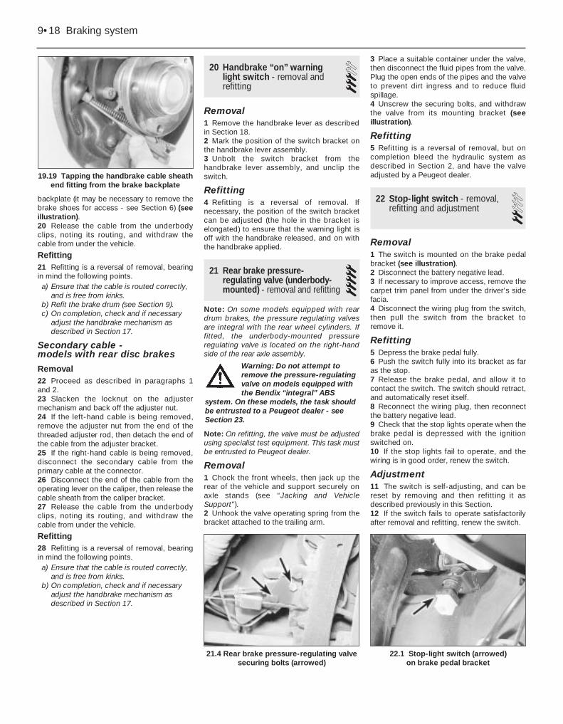
backplate (it may be necessary to remove thebrake shoes for access - see Section 6) (seeillustration).20 Release the cable from the underbodyclips, noting its routing, and withdraw thecable from under the vehicle.
Refitting21 Refitting is a reversal of removal, bearingin mind the following points.a) Ensure that the cable is routed correctly,
and is free from kinks.b) Refit the brake drum (see Section 9).c) On completion, check and if necessary
adjust the handbrake mechanism asdescribed in Section 17.
Secondary cable - models with rear disc brakes
Removal22 Proceed as described in paragraphs 1and 2.23 Slacken the locknut on the adjustermechanism and back off the adjuster nut.24 If the left-hand cable is being removed,remove the adjuster nut from the end of thethreaded adjuster rod, then detach the end ofthe cable from the adjuster bracket.25 If the right-hand cable is being removed,disconnect the secondary cable from theprimary cable at the connector.26 Disconnect the end of the cable from theoperating lever on the caliper, then release thecable sheath from the caliper bracket.27 Release the cable from the underbodyclips, noting its routing, and withdraw thecable from under the vehicle.
Refitting28 Refitting is a reversal of removal, bearingin mind the following points.a) Ensure that the cable is routed correctly,
and is free from kinks.b) On completion, check and if necessary
adjust the handbrake mechanism asdescribed in Section 17.
20 Handbrake “on” warninglight switch - removal andrefitting
3Removal1 Remove the handbrake lever as describedin Section 18.2 Mark the position of the switch bracket onthe handbrake lever assembly.3 Unbolt the switch bracket from thehandbrake lever assembly, and unclip theswitch.
Refitting4 Refitting is a reversal of removal. Ifnecessary, the position of the switch bracketcan be adjusted (the hole in the bracket iselongated) to ensure that the warning light isoff with the handbrake released, and on withthe handbrake applied.
21 Rear brake pressure-regulating valve (underbody-mounted) - removal and refitting
5Note: On some models equipped with reardrum brakes, the pressure regulating valvesare integral with the rear wheel cylinders. Iffitted, the underbody-mounted pressureregulating valve is located on the right-handside of the rear axle assembly.
Note: On refitting, the valve must be adjustedusing specialist test equipment. This task mustbe entrusted to Peugeot dealer.
Removal1 Chock the front wheels, then jack up therear of the vehicle and support securely onaxle stands (see “Jacking and VehicleSupport”).2 Unhook the valve operating spring from thebracket attached to the trailing arm.
3 Place a suitable container under the valve,then disconnect the fluid pipes from the valve.Plug the open ends of the pipes and the valveto prevent dirt ingress and to reduce fluidspillage.4 Unscrew the securing bolts, and withdrawthe valve from its mounting bracket (seeillustration).
Refitting5 Refitting is a reversal of removal, but oncompletion bleed the hydraulic system asdescribed in Section 2, and have the valveadjusted by a Peugeot dealer.
22 Stop-light switch - removal,refitting and adjustment 2
Removal1 The switch is mounted on the brake pedalbracket (see illustration).2 Disconnect the battery negative lead.3 If necessary to improve access, remove thecarpet trim panel from under the driver’s sidefacia.4 Disconnect the wiring plug from the switch,then pull the switch from the bracket toremove it.
Refitting5 Depress the brake pedal fully.6 Push the switch fully into its bracket as faras the stop.7 Release the brake pedal, and allow it tocontact the switch. The switch should retract,and automatically reset itself.8 Reconnect the wiring plug, then reconnectthe battery negative lead.9 Check that the stop lights operate when thebrake pedal is depressed with the ignitionswitched on.10 If the stop lights fail to operate, and thewiring is in good order, renew the switch.
Adjustment11 The switch is self-adjusting, and can bereset by removing and then refitting it asdescribed previously in this Section.12 If the switch fails to operate satisfactorilyafter removal and refitting, renew the switch.
9•18 Braking system
22.1 Stop-light switch (arrowed) on brake pedal bracket
21.4 Rear brake pressure-regulating valvesecuring bolts (arrowed)
19.19 Tapping the handbrake cable sheathend fitting from the brake backplate
Warning: Do not attempt toremove the pressure-regulatingvalve on models equipped withthe Bendix “integral” ABS
system. On these models, the task shouldbe entrusted to a Peugeot dealer - seeSection 23.
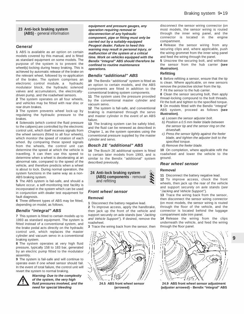
23 Anti-lock braking system(ABS) - general information
General1 ABS is available as an option on certainmodels covered by this manual, and is fittedas standard equipment on some models. Thepurpose of the system is to prevent thewheel(s) locking during heavy braking. This isachieved by automatic release of the brake onthe relevant wheel, followed by re-applicationof the brake. The system comprises anelectronic control module, a hydraulicmodulator block, the hydraulic solenoidvalves and accumulators, the electrically-driven pump, and the roadwheel sensors.2 The system operates on all four wheels,and vehicles may be fitted with rear disc orrear drum brakes.3 The system prevents wheel lock-up byregulating the hydraulic pressure to thebrakes.4 Solenoids (which control the fluid pressureto the calipers) are controlled by the electroniccontrol unit, which itself receives signals fromthe wheel sensors (fitted to all four wheels),which monitor the speed of rotation of eachwheel. By comparing these speed signalsfrom the wheels, the control unit candetermine the speed at which the vehicle istravelling. It can then use this speed todetermine when a wheel is decelerating at anabnormal rate, compared to the speed of thevehicle, and therefore predicts when a wheelis about to lock. During normal operation, thesystem functions in the same way as a non-ABS braking system.5 The ABS system is fail-safe, and should afailure occur, a self-monitoring test facility isincorporated in the system which can be usedin conjunction with dealer test equipment forfault diagnosis.6 Three different types of ABS may be fitted,depending on model, as follows.
Bendix “integral” ABS7 This system is fitted to certain models up to1993 as standard equipment. The system isfitted instead of a conventional system, andthe brake pedal acts directly on the hydrauliccontrol unit, which replaces the mastercylinder and vacuum servo in a conventionalbraking system.8 The system operates at very high fluidpressure, typically 158 to 183 bar, generatedby an electric pump fitted to the modulatorassembly.9 The system is fail-safe and will continue tooperate even if one wheel sensor should fail.In the event of total failure, the control unit willrevert the system to normal braking.
Bendix “additional” ABS10 The Bendix “additional” system is fitted asan option to certain models, and the ABScomponents are fitted in addition to theconventional braking system components.11 The system uses the pressure providedby the conventional master cylinder andvacuum servo.12 The system is fail-safe, and conventionalbraking is maintained through the servo and master cylinder in the event of an ABSfailure.13 The braking system can be safely bled,and the fluid can be renewed as described inChapter 1, as the system operates using theconventional pressure supplied by the mastercylinder and servo.
Bosch 2E “additional” ABS14 The Bosch 2E additional system is fittedto certain later models from 1993, and issimilar to the Bendix “additional” systemdescribed previously.
24 Anti-lock braking system(ABS) components - removaland refitting
4Front wheel sensor
Removal1 Disconnect the battery negative lead.2 To improve access, apply the handbrake,then jack up the front of the vehicle andsupport securely on axle stands (see “Jackingand Vehicle Support”). If desired, remove theroadwheel.3 Trace the wiring back from the sensor, then
disconnect the sensor wiring connector (onmost models, the sensor wiring is routedthrough the inner wing panel, and theconnector is located in the enginecompartment.4 Release the sensor wiring from anysecuring clips and, where applicable, pushthe wiring grommet from the inner wing paneland feed the wiring through the panel.5 Unscrew the securing bolt, and withdrawthe sensor from the hub carrier (seeillustration).
Refitting6 Before refitting a sensor, ensure that the tipis clean. Where applicable, on new sensorsremove the protective sticker from the tip.7 Fit the sensor to the hub carrier.8 Clean the sensor securing bolt, then applythread-locking compound to the bolt threads.Fit the bolt and tighten to the specified torque.9 On models fitted with the Bendix “integral”ABS system, proceed as follows (seeillustration).a) Loosen the sensor adjuster bolt.b) Position a 0.5 mm feeler blade between
the sensor tip and the sensor ring on thedriveshaft.
c) Press the sensor lightly against the feelerblade, and tighten the adjuster bolt to thespecified torque.
d) Remove the feeler blade.10 On completion, where applicable refit theroadwheel and lower the vehicle to theground.
Rear wheel sensor
Removal11 Disconnect the battery negative lead.12 To improve access, chock the frontwheels, then jack up the rear of the vehicleand support securely on axle stands (see“Jacking and Vehicle Support”).13 Trace the wiring back from the sensor,then disconnect the sensor wiring connector(on most models, the sensor wiring is routedthrough the floor of the vehicle, and theconnector is located behind the luggagecompartment side trim panel.14 Release the wiring from the clipsunderneath the vehicle, and feed the wiringthrough the floor panel.
Braking system 9•19
24.9 ABS front wheel sensor adjustment(adjuster arrowed) - Bendix “integral” ABS
24.5 ABS front wheel sensor (arrowed)
9
Warning: Due to the complexityof the system, the very highfluid pressures involved, and theneed for special bleeding
equipment and pressure gauges, anyoperation requiring removal ordisconnection of any hydrauliccomponent, pipe or fitting must only becarried out by a suitably-equippedPeugeot dealer. Failure to heed thiswarning may result in personal injury, ormalfunction of the system at a criticaltime. Work on vehicles equipped with theBendix “integral” ABS should therefore beconfined to routine maintenanceoperations.

15 Unscrew the securing bolt, and removethe sensor from the trailing arm (seeillustration).
Refitting16 Before refitting a sensor, ensure that thetip is clean. Where applicable, on new sensorsremove the protective sticker from the tip.17 Lightly grease the sensor location in thetrailing arm, then refit the sensor.18 Clean the sensor securing bolt, then applythread-locking compound to the bolt threads.Fit the bolt and tighten to the specified torque.
Electronic control unit - Bendix ABS systems
Removal19 Disconnect the battery negative lead.20 The unit is located in the scuttle at the rearof the engine compartment (see illustration).21 Open the bonnet, and unclip the coverfrom the top of the scuttle to expose thecontrol unit.22 Release the securing clip, and disconnectthe wiring plug from the top of the control unit.23 Unscrew the clamp bolts or nuts, asapplicable, securing the unit to the housing,then carefully withdraw the unit. Note that onsome models, it may be necessary todisconnect the control unit wiring harnessearth lead before the unit can be withdrawn.24 Where applicable, separate the controlunit from the mounting bracket.
Refitting25 Refitting is a reversal of removal, butwhere applicable ensure that the wiringharness earth lead is securely reconnected.
Electronic control unit - Bosch ABS system
Removal26 Disconnect the battery negative lead, then
unclip the control unit cover from the top ofthe modulator assembly.27 Disconnect the three wiring connectorsfrom the control unit, then slacken andremove the six Torx retaining screws, and liftthe control unit away from the modulatorassembly (see illustration).
Refitting28 Refitting is a reversal of the removalprocedure. Ensure that the wiring connectorsare securely reconnected, and do notovertighten the retaining screws.
Hydraulic control unit and modulator assembly -Bendix “integral” ABSNote: Refer to the Warning in Section 23.29 No attempt should be made to removeany of the hydraulic system components onmodels equipped with the Bendix “integral”ABS - refer the operation to a Peugeot dealer.
Modulator assembly - Bendix “additional” ABS
Removal30 Disconnect the battery negative lead.
31 Where applicable, unclip the plasticcover, then disconnect the wiring connectorsfrom the modulator assembly.32 Mark the locations of the hydraulic fluidpipes to ensure correct refitting, then unscrewthe union nuts, and disconnect the pipes fromthe modulator assembly. Be prepared for fluidspillage, and plug the open ends of the pipesand the modulator, to prevent dirt ingress andfurther fluid loss. Note the position of the clipon the brake pipes to ensure correct refitting.33 Working under the modulator, unscrewthe two nuts securing the vertical mountingplate to the main bracket (see illustration).Withdraw the plate and the mounting rubberassembly.34 Unscrew the two nuts securing theremaining mounting studs to the mainbracket, then manipulate the modulatorassembly from the bracket.
Refitting
35 Refitting is a reversal of removal, bearingin mind the following.a) Before refitting, examine the mounting
rubbers, and renew if necessary.b) Reconnect the fluid pipes to the
assembly, as noted before removal,ensuring that no dirt enters the system.Ensure that the brake pipe clip is fitted asnoted before removal.
c) Before reconnecting the wiringconnectors, bleed the complete hydraulicsystem as described in Section 2.
Modulator assembly - Bosch ABS36 Refer to paragraphs 30 to 35 of thisSection for the Bendix “additional” ABS.
9•20 Braking system
24.15 Rear wheel ABS sensor (arrowed)
24.27 Bosch ABS electronic control unit
securing screws (arrowed)
24.33 Modulator assembly verticalmounting bracket-to-main bracket nuts
(arrowed) - Bendix “additional” ABS
24.20 Electronic control unit location(arrowed) - Bendix “integral” ABS (left-hand-drive models shown)
Warning: Do not reconnect thewiring connectors to themodulator until the hydrauliccircuits have been bled asdescribed in Section 2.

10
Wheel alignment and steering anglesFront wheel toe setting . . . . . . . . . . . . . . . . . . . . . . . . . . . . . . . . . . . . . . 1.0 ± 0.5 mm toe-in
RoadwheelsType . . . . . . . . . . . . . . . . . . . . . . . . . . . . . . . . . . . . . . . . . . . . . . . . . Pressed steel or aluminium alloy (depending on model)Size . . . . . . . . . . . . . . . . . . . . . . . . . . . . . . . . . . . . . . . . . . . . . . . . . 5.5J x 14 or 6J x 15
Torque wrench settings Nm lbf ft
Front suspensionHub carrier-to-suspension strut clamp nut/bolt:*
Early (solid) type hub carrier . . . . . . . . . . . . . . . . . . . . . . . . . . . . . . . . 55 41Later (hollow) type hub carrier . . . . . . . . . . . . . . . . . . . . . . . . . . . . . . 45 33
Suspension strut top mounting nuts:Models up to 1992 . . . . . . . . . . . . . . . . . . . . . . . . . . . . . . . . . . . . . . . 25 18Models from 1993 . . . . . . . . . . . . . . . . . . . . . . . . . . . . . . . . . . . . . . . . 20 15
Suspension strut upper mounting retaining nut . . . . . . . . . . . . . . . . . . . 55 41Lower balljoint nut (hub carrier-to-lower arm):*
Early (solid) type hub carrier . . . . . . . . . . . . . . . . . . . . . . . . . . . . . . . . 30 22Later (hollow) type hub carrier . . . . . . . . . . . . . . . . . . . . . . . . . . . . . . 45 33
Lower arm front pivot nut/bolt . . . . . . . . . . . . . . . . . . . . . . . . . . . . . . . . 75 55Lower arm rear securing nuts/bolts
Models up to 1992 . . . . . . . . . . . . . . . . . . . . . . . . . . . . . . . . . . . . . . . 45 33Models from 1993 . . . . . . . . . . . . . . . . . . . . . . . . . . . . . . . . . . . . . . . . 70 52
Anti-roll bar-to-subframe clamp bolts . . . . . . . . . . . . . . . . . . . . . . . . . . 25 18Anti-roll bar metal clamp bolts . . . . . . . . . . . . . . . . . . . . . . . . . . . . . . . . 20 15Anti-roll bar drop link-to-anti-roll bar nuts/bolts . . . . . . . . . . . . . . . . . . . 65 48Anti-roll bar drop link-to-lower arm bolts:
Models up to 1992 . . . . . . . . . . . . . . . . . . . . . . . . . . . . . . . . . . . . . . . 75 55Models from 19943 . . . . . . . . . . . . . . . . . . . . . . . . . . . . . . . . . . . . . . . 65 48
Subframe front securing bolts:Models up to 1992 . . . . . . . . . . . . . . . . . . . . . . . . . . . . . . . . . . . . . . . 60 44Models from 1993 . . . . . . . . . . . . . . . . . . . . . . . . . . . . . . . . . . . . . . . . 55 41
Chapter 10Suspension and steering
Front hub bearings - renewal . . . . . . . . . . . . . . . . . . . . . . . . . . . . . . . .3Front hub carrier assembly - removal and refitting . . . . . . . . . . . . . . .2Front suspension and steering check . . . . . . . . . . . . . . .See Chapter 1Front anti-roll bar components - removal and refitting . . . . . . . . . . . .8Front suspension lower arm - removal and refitting . . . . . . . . . . . . . . .6Front suspension lower balljoint - removal and refitting . . . . . . . . . . . .7Front suspension strut - overhaul . . . . . . . . . . . . . . . . . . . . . . . . . . . . .5Front suspension strut - removal and refitting . . . . . . . . . . . . . . . . . . .4Front suspension subframe - removal and refitting . . . . . . . . . . . . . . .9General information . . . . . . . . . . . . . . . . . . . . . . . . . . . . . . . . . . . . . . .1Ignition switch/steering column lock - removal and refitting . . . . . . .18Power steering pump - removal and refitting . . . . . . . . . . . . . . . . . . .22Power steering pump drivebelt check, adjustment
andrenewal . . . . . . . . . . . . . . . . . . . . . . . . . . . . . . . . .See Chapter 1Power steering fluid level check . . . . . . . . . . . . . .See “Weekly checks”
Power steering system - bleeding . . . . . . . . . . . . . . . . . . . . . . . . . . .21Rear axle assembly - removal and refitting . . . . . . . . . . . . . . . . . . . .14Rear hub assembly - removal and refitting . . . . . . . . . . . . . . . . . . . . .10Rear hub bearing - renewal . . . . . . . . . . . . . . . . . . . . . . . . . . . . . . . .11Rear shock absorber - removal, testing and refitting . . . . . . . . . . . . .13Rear suspension components - general . . . . . . . . . . . . . . . . . . . . . . .12Steering column - removal, inspection and refitting . . . . . . . . . . . . . .17Steering gear assembly - removal, overhaul and refitting . . . . . . . . .19Steering gear rubber gaiters - renewal . . . . . . . . . . . . . . . . . . . . . . . .20Steering wheel - removal and refitting . . . . . . . . . . . . . . . . . . . . . . . .16Track rod - removal and refitting . . . . . . . . . . . . . . . . . . . . . . . . . . . .24Track rod end - removal and refitting . . . . . . . . . . . . . . . . . . . . . . . . .23Vehicle ride height - checking . . . . . . . . . . . . . . . . . . . . . . . . . . . . . .15Wheel alignment and steering angles - general information . . . . . . .25Wheel and tyre maintenance . . . . . . . . . . . . . . . .See “Weekly checks”
10•1
Specifications
Contents
Easy, suitable fornovice with littleexperience
Fairly easy, suitablefor beginner withsome experience
Fairly difficult,suitable for competentDIY mechanic
Difficult, suitable forexperienced DIYmechanic
Very difficult,suitable for expert DIYor professional
Degrees of difficulty
54321

1 General information
The independent front suspension is of theMacPherson strut type, incorporating coilsprings and integral telescopic shockabsorbers. The MacPherson struts arelocated by transverse lower suspension arms,which utilise rubber inner mounting bushes.The front hub carriers, which carry the wheelbearings, brake calipers and the hub/discassemblies, are bolted to the MacPhersonstruts. The hub carriers are connected to thelower arms via balljoints attached to the hubcarriers. A front anti-roll bar is fitted to allmodels. The anti-roll bar is rubber-mountedonto the subframe, and is connected to thelower arms via drop links.
The rear suspension is of the semi-independent trailing arm type, which consistsof two trailing arms, linked by a tubularcrossmember. A torsion bar is fittedtransversely between each trailing arm andthe opposite suspension side member. Ananti-roll bar is fitted between the trailing arms.The complete rear axle assembly is mountedonto the vehicle underbody via four rubbermountings.
The steering column has a universal jointfitted in the centre of its length, which isconnected to an intermediate shaft having asecond universal joint at its lower end. Thelower universal joint is clamped to the steeringgear pinion by means of a clamp bolt.
The steering gear is mounted onto the frontsubframe, and is connected by two trackrods, with balljoints at their outer ends, to thesteering arms projecting rearwards from theswivel hubs. The track rod ends are threaded,to facilitate adjustment.
Power-assisted steering is fitted asstandard on some models, and is available asan option on most others. The hydraulicpower steering system is powered by a belt-driven pump, which is driven off thecrankshaft pulley.
2 Front hub carrier assembly -removal and refitting 3
RemovalNote: All Nyloc nuts disturbed on removalmust be renewed as a matter of course. Thesenuts have threads which are pre-coated withlocking compound (this is only effective once).A balljoint separator tool will be required forthis operation.Note: Do not allow the vehicle to rest on itswheels with one or both driveshaftsdisconnected from the swivel hubs, asdamage to the wheel bearing(s) may result. Ifmoving the vehicle is unavoidable, temporarilyinsert the outer end of the driveshaft(s) in thehub(s) and tighten the hub nut(s).Note: It is recommended that a coil springcompressor tool is used during the removaland refitting of the hub carrier. The hub carrier
can be removed without a spring compressor,but because of the long length of the strutwith the spring in a released state, it is difficultto separate the hub carrier from the strut, andunacceptable strain could be exerted on thedriveshaft joint. Do not attempt to use a make-shift method of compressing the spring, asthere is a risk of component damage andpersonal injury.Note: Two different types of hub carrierassembly may be fitted, depending on model.The earlier hub carriers are solid. The later hubcarriers are hollow, and can be identified fromthe hole at the top of the assembly (seeillustration 2.19a). When refitting note thatthe torque wrench settings differ for the twotypes of hub carrier (see “Specifications”).Modified lower arms are fitted in conjunctionwith the later hub carriers, and the early andlate type components are not interchangeable- if components are renewed, make sure thatthe correct new parts are obtained.1 Chock the rear wheels, then firmly apply thehandbrake. Jack up the front of the vehicle,and support it on axle stands (see “Jackingand Vehicle Support”). Remove theappropriate front roadwheel.2 On models with ABS, remove the wheelsensor as described in Chapter 9.3 Remove the R-clip, and withdraw thelocking cap from the driveshaft retaining nut(see illustration).4 Refit at least two roadwheel bolts to thefront hub, and tighten them securely. Have anassistant firmly depress the brake pedal, toprevent the front hub from rotating, then using
Torque wrench settings Nm lbf ft
Front suspension (continued)Subframe rear securing bolts:
M12 bolts . . . . . . . . . . . . . . . . . . . . . . . . . . . . . . . . . . . . . . . . . . . . . . 90 66M14 bolts . . . . . . . . . . . . . . . . . . . . . . . . . . . . . . . . . . . . . . . . . . . . . . 150 111
Lower balljoint to hub carrier:*Early (solid) type hub carrier . . . . . . . . . . . . . . . . . . . . . . . . . . . . . . . . 260 192 Later (hollow) type hub carrier . . . . . . . . . . . . . . . . . . . . . . . . . . . . . . 250 184
Rear suspensionRear hub nut . . . . . . . . . . . . . . . . . . . . . . . . . . . . . . . . . . . . . . . . . . . . . . 275 200Shock absorber securing nuts/ bolts . . . . . . . . . . . . . . . . . . . . . . . . . . . 110 81Suspension assembly-to-rear mounting bolts . . . . . . . . . . . . . . . . . . . . 25 18Suspension assembly-to-front mounting nuts . . . . . . . . . . . . . . . . . . . . 60 44Rear suspension mounting-to-body bolts . . . . . . . . . . . . . . . . . . . . . . . 55 41Front suspension mounting-to-body bolts . . . . . . . . . . . . . . . . . . . . . . . 55 41
SteeringSteering wheel securing nut . . . . . . . . . . . . . . . . . . . . . . . . . . . . . . . . . . 35 26Universal joint clamp bolt . . . . . . . . . . . . . . . . . . . . . . . . . . . . . . . . . . . . 20 15Steering gear-to-subframe bolts:
Models up to 1992 . . . . . . . . . . . . . . . . . . . . . . . . . . . . . . . . . . . . . . . 40 35Models from 1993 . . . . . . . . . . . . . . . . . . . . . . . . . . . . . . . . . . . . . . . . 90 66
Track rod end balljoint nut:*Early (solid) type hub carrier . . . . . . . . . . . . . . . . . . . . . . . . . . . . . . . . 45 33Later (hollow) type hub carrier . . . . . . . . . . . . . . . . . . . . . . . . . . . . . . 35 26
Track rod end locknut . . . . . . . . . . . . . . . . . . . . . . . . . . . . . . . . . . . . . . . 45 33
RoadwheelsWheel bolts . . . . . . . . . . . . . . . . . . . . . . . . . . . . . . . . . . . . . . . . . . . . . . . 85 63*See note in Section 2.
10•2 Suspension and steering

a socket and extension bar, slacken andremove the driveshaft retaining nut.Alternatively, a tool can be fabricated fromtwo lengths of steel strip (one long, one short)and a nut and bolt; the nut and bolt formingthe pivot of a forked tool. Bolt the tool to thehub using two wheel bolts, and hold the toolto prevent the hub from rotating as thedriveshaft nut is undone.5 Unscrew the two bolts securing the brakecaliper/mounting bracket assembly to theswivel hub, and slide the caliper assembly offthe disc. Recover the mounting plate, whereapplicable. Using a piece of wire or string, tiethe caliper to the front suspension coil spring,to avoid placing any strain on the hydraulicbrake hose.6 Use chalk or paint to mark the relationshipof the disc to the hub, then remove thescrew(s) securing the brake disc to the hub,and remove the disc. If it is tight, lightly tap itsrear face with a hide or plastic mallet.7 Where applicable, slacken and remove thebolt securing the wiring/hose retainingbracket to the top of the hub carrier.8 To ease removal of the hub carrier, fitspring compressor tools to the coil spring onthe strut, in accordance with themanufacturer’s instructions, and lightlytighten the compressors. Note that the hubcarrier can be removed without using springcompressors, but difficulty may beencountered disconnecting hub carrier fromthe lower end of the strut.9 Unscrew the bolt securing the anti-roll bardrop link to the lower arm.
10 Slacken and partially unscrew the trackrod end nut (unscrew the nut as far as the endof the threads on the balljoint to preventdamage to the threads as the joint isreleased), then release the balljoint using aballjoint separator tool. Remove the nut.11 Similarly, slacken the lower balljoint nut(securing the hub carrier to the lower arm),then release the balljoint using a separatortool (see illustration). Remove the nut.12 Undo the nut and withdraw the hubcarrier-to-suspension strut clamp bolt, notingthat the bolt fits from the rear of the vehicle(see illustration).13 Where applicable, tighten the compressortools, and compress the spring sufficiently toenable the lower end of the strut to bedisconnected from the hub carrier.14 Insert a lever into the slot in the hubcarrier, and spread the slot until the hubcarrier can be released from the strut.
15 Free the hub carrier assembly from theend of the strut, then release it from the outerconstant velocity joint splines, and remove itfrom the vehicle. If necessary, tap the end ofthe driveshaft (using a soft-faced mallet) tofree it from the hub carrier. Support the free,outboard end of the driveshaft by suspendingit using wire or string - do not allow thedriveshaft to hang down under its own weight.
Refitting16 Where applicable, fit the springcompressor tools in position as duringremoval, ensure that the driveshaft outerconstant velocity joint and hub splines areclean, then slide the hub fully onto thedriveshaft splines.17 Slide the hub carrier assembly fully ontothe suspension strut, aligning the slot in thehub carrier with the lug on the base of thestrut. Also ensure that the stop boss on thestrut is in contact with the top surface of thehub carrier (see illustration). Release the toolused to spread the hub carrier slot.18 Insert the hub carrier-to-suspension strutclamp bolt from the rear side of the strut, thenfit a new nut to the clamp bolt, and tighten itto the specified torque.19 Two types of hub carrier may be fitted.The later type can be identified from the holeat the top of the assembly (see illustration).When refitting a later type hub carrier,proceed as follows.
a) After tightening the clamp bolt, measurethe gap between the hub carrier clamplugs (see illustration). The gap must notbe less than specified. If the gap is lessthan specified, proceed as follows.
b) Check the condition of the lower end ofthe strut. If the strut cylinder has beencrushed, the shock absorber will bedamaged, and the strut must be renewed.
c) If the strut is not damaged, but the gapbetween the clamp lugs is still less thanspecified, renew the hub carrier.
Suspension and steering 10•3
2.12 Hub carrier-to-suspension strutclamp nut (arrowed)
2.19b Gap (A) on later type hub carrierclamp lugs must not be less than 6.5 mm
2.19a Later type hub carrier with identification hole (arrowed)
2.17 Lug (1) and stop boss (2) on lower end of strut
2.11 Release the lower balljoint using aballjoint separator tool
2.3 Withdraw the R-clip from thedriveshaft nut locking cap
10
To spread the slot in the hubcarrier, engage an 8.0 mmAllen key or hexagon bit inthe slot, then turn the key/bitto spread the slot.

20 Align the balljoint with the lower arm, thenfit the balljoint nut, and tighten to the specifiedtorque.21 Engage the track rod balljoint in the hubcarrier, then fit a new retaining nut and tightenit to the specified torque.22 Refit the bolt securing the anti-roll bardrop link to the lower arm, and tighten to thespecified torque.23 Refit the brake disc to the hub, ensuringthat the marks made before removal arealigned, then refit the brake caliper/mountingbracket. Apply suitable locking fluid to thecaliper/mounting bracket bolts then, whereapplicable refit the mounting plate, ensuringthat the plate is fitted so that its bend curvesaway from the caliper body, and refit thebolts. Tighten the bolts to the specifiedtorque.24 Lubricate the inner face and threads ofthe driveshaft retaining nut with clean engineoil, and refit it to the end of the driveshaft. Usethe method employed on removal to preventthe hub from rotating, and tighten thedriveshaft retaining nut to the specified torque(see Chapter 8). Check that the hub rotatesfreely.25 Engage the locking cap with thedriveshaft nut so that one of its cut-outs isaligned with the driveshaft hole. Secure thecap with the R-clip.26 Where applicable, slacken and removethe spring compressor tools.27 Where applicable, refit the ABS wheelsensor as described in Chapter 9.28 Where applicable, refit the wiring retainingbracket to the top of the hub carrier, andtighten its retaining bolt securely. Ensure thatthe earth lead is in position beneath the bolt,where applicable.29 Refit the roadwheel, then lower thevehicle to the ground and tighten theroadwheel bolts to the specified torque.
3 Front hub bearings - renewal 4Note: The bearing is a sealed, pre-adjustedand pre-lubricated, double-row roller type,and is intended to last the car’s entire servicelife without maintenance or attention. Neverovertighten the driveshaft nut beyond thespecified torque wrench setting in an attemptto “adjust” the bearing.Note: A press will be required to dismantleand rebuild the assembly; if such a tool is notavailable, a large bench vice and spacers(such as large sockets) will serve as anadequate substitute. The bearing’s inner racesare an interference fit on the hub; if the innerrace remains on the hub when it is pressedout of the hub carrier, a knife-edged bearingpuller will be required to remove it.1 Remove the hub carrier assembly asdescribed in Section 2.2 Support the hub carrier securely on blocks
or in a vice. Using a tubular spacer whichbears only on the inner end of the hub flange,press the hub flange out of the bearing. If thebearing’s outboard inner race remains on thehub, remove it using a bearing puller (see noteabove).3 Extract the bearing retaining circlip from theinner end of the hub carrier assembly (seeillustration).4 Where necessary, refit the inner race backin position over the ball cage, and securelysupport the inner face of the hub carrier.Using a tubular spacer which bears only onthe inner race, press the complete bearingassembly out of the hub carrier.5 Thoroughly clean the hub and hub carrier,removing all traces of dirt and grease, andpolish away any burrs or raised edges whichmight hinder reassembly. Check both forcracks or any other signs of wear or damage,and renew them if necessary. Renew thecirclip, regardless of its apparent condition.6 On reassembly, apply a light film of oil tothe bearing outer race and hub flange shaft, toaid installation of the bearing.7 Securely support the hub carrier, and locatethe bearing in the hub. Press the bearing fullyinto position, ensuring that it enters the hubsquarely, using a tubular spacer which bearsonly on the bearing outer race.8 Once the bearing is correctly seated,secure the bearing in position with the newcirclip, ensuring that it is correctly located inthe groove in the hub carrier.9 Securely support the outer face of the hubflange, and locate the hub carrier bearinginner race over the end of the hub flange.
Press the bearing onto the hub, using atubular spacer which bears only on the innerrace of the hub bearing, until it seats againstthe hub shoulder. Check that the hub flangerotates freely, and wipe off any excess oil orgrease.10 Refit the hub carrier assembly asdescribed in Section 2.
4 Front suspension strut -removal and refitting 3
RemovalNote: All Nyloc nuts disturbed on removalmust be renewed as a matter of course. Thesenuts have threads which are pre-coated withlocking compound (this is only effective once).Note: It is recommended that a coil springcompressor tool is used during the removaland refitting of the strut. The strut can beremoved without a spring compressor, butbecause of the long length of the strut with thespring in a released state, it is difficult toseparate the hub carrier from the strut, andunacceptable strain could be exerted on thedriveshaft joint. Do not attempt to use a make-shift method of compressing the spring, asthere is a risk of component damage andpersonal injury.1 Chock the rear wheels, apply thehandbrake, then jack up the front of thevehicle and support on axle stands (see“Jacking and Vehicle Support”). Remove theappropriate roadwheel.2 Working in the engine compartment, wereapplicable remove the plastic cover from thestrut top mounting, then slacken but do notremove the two strut top mounting nuts (seeillustration).3 Where applicable, unclip any wiring and/orhoses from the strut.4 Unscrew the bolt securing the anti-roll bardrop link to the strut.5 Undo the nut and withdraw the hub carrier-to-suspension strut clamp bolt, noting that thebolt fits from the rear of the strut (seeillustration). Discard the nut - a new one mustbe used on refitting.6 To ease removal of the hub carrier, fit springcompressor tools to the coil spring on the strut,
10•4 Suspension and steering
3.3 Front hub bearing retaining circlip(arrowed)
4.5 Unscrewing the hub carrier-to-suspension strut clamp bolt
4.2 Suspension strut top mounting nuts(arrowed)

in accordance with the manufacturer’sinstructions, and lightly tighten thecompressors. Note that the strut can beremoved without using spring compressors, butdifficulty may be encountered disconnectinghub carrier from the lower end of the strut.7 Insert a lever into the slot in the hub carrier,and spread the slot until the hub carrier canbe released from the strut.
8 Free the hub carrier from the strut, thenremove the two strut top mounting nuts, andwithdraw the strut from under the wheel arch.
Refitting9 Where applicable, fit the coil springcompressors as during removal, thenmanoeuvre the strut assembly into position.Feed the top mounting studs through theholes in the body, and fit the mounting nuts.10 Engage the lower end of the strut with thehub carrier. Align the slot in the hub carrierwith the lug on the base of the strut. Alsoensure that the stop bosses on the strut are incontact with the top surface of the hub carrier.Release the tool used to spread the hubcarrier slot.11 Insert the hub carrier-to-suspension strutclamp bolt from the rear side of the strut, thenfit a new nut to the clamp bolt, and tighten itto the specified torque.
12 Refit the bolt securing the anti-roll bardrop link to the strut.13 Tighten the two strut top mounting nuts tothe specified torque.14 Where applicable, carefully slacken andthen remove the spring compressors.15 Where applicable, clip any wiring/hosesinto position on the strut.16 Refit the roadwheel, then lower thevehicle to the ground and tighten theroadwheel bolts to the specified torque.
5 Front suspension strut -overhaul 3
Note: The components encountered may varyin detail, but the principles described in thefollowing paragraphs are equally applicable toall models. Make a careful note of the fittedpositions of all components beforedismantling.1 With the strut removed as described inSection 4, clean the exterior of the unit, thenmount it in a soft-jawed vice.
2 If not already done, fit coil springcompressors in accordance with themanufacturer’s instructions, and compressthe spring until the pressure on the topmounting is relieved.3 Unscrew the top mounting nut. Use a ringspanner to unscrew the nut, and counterholdthe piston rod using a 7.0 mm Allen key (seeillustration).4 Remove the nut and recover the washer,then lift off the cupped washer, mountingplate, rubber buffer, and the two dishedplates.5 Lift off the upper spring seat.6 Withdraw the washer and the rubber gaiter.7 Remove the bump stop.8 Remove the coil spring. If the spring is to berenewed, remove the compressors, otherwiseleave them in position for reassembly.9 Inspect the strut for signs of leakage fromthe piston rod seal. With the strut heldvertically, operate the piston over its full rangeof movement in both directions, checking thatthe resistance is even and firm. If theresistance is weak or jerky, if there is any fluidseepage, or if there is any damage to the strutor corrosion of the piston rod, then strut mustbe renewed. Note that struts should alwaysbe renewed in pairs. At the same time, checkthe coil spring for condition, and any signs ofdistortion or damage. If spring renewal isnecessary, again note that both front springsshould be renewed as a pair.10 Reassemble the strut using a reversal ofthe dismantling procedure, and following theaccompanying illustration sequence (seeillustrations 5.10a to 5.10l).
Suspension and steering 10•5
5.10b . . . making sure the lower end of thespring locates against the stop (arrowed)
5.10e . . . and the washer . . .5.10c Refit the bump stop . . . 5.10d . . . followed by the rubber gaiter . . .
5.10a Refit the coil spring, with thecompressors in position . . .
5.3 Counterhold the piston rod andunscrew the top mounting nut
10
To spread the slot in the hubcarrier, engage an 8.0 mmAllen key or hexagon bit inthe slot, then turn thekey/bit to spread the slot.
Warning: Before attempting todismantle the front suspensionstrut, a suitable tool to hold thecoil spring in compression must
be obtained. Adjustable coil springcompressors are readily-available, and arerecommended for this operation. Anyattempt to dismantle the strut withoutsuch a tool is likely to result in damage orpersonal injury.

6 Front suspension lower arm - removal, overhaul and refitting
4RemovalNote: All Nyloc nuts disturbed on removalmust be renewed as a matter of course. Thesenuts have threads which are pre-coated withlocking compound (this is only effective once).A balljoint separator tool will be required forthis operation.Note: Two different types of hub carrierassembly may be fitted, depending on model.The earlier hub carriers are solid. The later hubcarriers are hollow, and can be identified fromthe hole at the top of the assembly (seeillustration 2.19a). When refitting note thatthe torque wrench settings differ for the twotypes of hub carrier (see “Specifications”).Modified lower arms are fitted in conjunctionwith the later hub carriers, and the early andlate type components are not interchangeable
- if components are renewed, make sure thatthe correct new parts are obtained.1 Apply the handbrake, then jack up the frontof the vehicle and support on axle stands (see“Jacking and Vehicle Support”). Remove therelevant roadwheel.2 Remove the bolt securing the anti-roll bardrop link to the lower arm (see illustration).3 Slacken and partially unscrew the lowerballjoint nut (unscrew the nut as far as the endof the threads on the balljoint to preventdamage to the threads as the joint isreleased), then release the balljoint using aballjoint separator tool. Remove the nut.4 Counterhold the nut, and unscrew the lowerarm front pivot bolt (see illustration).Withdraw the bolt.5 Unscrew the two lower arm rear securingnuts (see illustration).6 Working at the rear of the subframe, loosenthe two subframe rear mounting bolts to allowthe rear of the subframe to be lowered
sufficiently for the lower arm rear clamp studsto clear the subframe (approximately 10.0mm). Note that the subframe bolts may becovered by plastic plugs on certain models(see illustration 6.5).7 Withdraw the lower arm.
6.2 Remove the bolt securing the anti-roll bar drop link to the lower arm
5.10l . . . and the plain washer and nut
6.4 Lower arm front pivot nut (arrowed)
6.5 Lower arm rear securing nuts (A) and subframe rear mounting bolt (B)
10•6 Suspension and steering
5.10f . . . fit the upper spring seat, followed by . . .
5.10h . . . and upper dished plates . . .
5.10k . . . the cupped washer . . .5.10j . . . the mounting plate . . .5.10i . . . the rubber buffer . . .
5.10g . . . the lower . . .

Overhaul8 Thoroughly clean the lower arm and thearea around the arm mountings, removing alltraces of dirt and underseal if necessary, thencheck carefully for cracks, distortion or anyother signs of wear or damage, payingparticular attention to the mounting bushes,and renew components as necessary.9 Examine the shank of the pivot bolt forsigns of wear or scoring, and renew ifnecessary.10 Examine the mounting bushes fordeterioration or damage.11 The mounting bushes can be renewed,but a press or suitable alternative tools will berequired. If the rear mounting bush isrenewed, it must be pressed into the positionshown, and the marks on the bush and thelower arm must be aligned. Note that somebushes have two alignment marks, in whichcase the mark nearest the bolt hole should beignored. Use a little silicon lubricant to aidfitting of the bushes (see illustrations).
Refitting12 Refitting is a reversal of removal, bearingin mind the following points.a) Renew all Nyloc nuts.b) Tighten all fixings to the specified torque.c) On completion, have the front wheel
alignment checked at the earliestopportunity with reference to Section 25.
7 Front suspension lowerballjoint - removal andrefitting
5Note: Peugeot special tool (-).0615.J will berequired to unscrew and tighten the balljoint. Ifthis tool is not available, the task should beentrusted to a Peugeot dealer. Do not attemptthe work using an improvised tool.
Removal1 Remove the hub carrier as described inSection 2.2 Tap the dust shield from the balljoint, usinga drift (see illustration).3 Fit the special tool (-).0615.J to the balljoint,engaging the tool with the cut-outs in theballjoint, and secure it by screwing the toollocknut onto the threaded section of theballjoint (see illustration). Engage a swing baror wrench with the tool, and unscrew theballjoint.
Refitting4 Refitting is a reversal of removal, bearing inmind the following points.a) Tighten the balljoint as far as possible by
hand before finally tightening to thespecified torque using the special tool.
b) Take care not to damage the balljointrubber gaiter during fitting.
c) Lock the balljoint in position by stakinginto one of the notches in the hub carrier.
d) Lock the dust shield in position by stakingit in one of the cut-outs in the balljoint.
e) Refit the hub carrier as described inSection 2.
8 Front anti-roll barcomponents - removal and refitting
3Anti-roll bar
RemovalNote: All Nyloc nuts disturbed on removalmust be renewed as a matter of course. Thesenuts have threads which are pre-coated withlocking compound (this is only effective once).Note: After refitting, the anti-roll baradjustment should be checked by a Peugeotdealer at the earliest opportunity (thesuspension must be compressed usingspecial equipment in order to carry out thecheck).1 Apply the handbrake, then jack up the frontof the vehicle and support on axle stands (see“Jacking and Vehicle Support”). Remove theroadwheels.2 Remove the bolts securing the anti-roll bardrop links to the lower arms.3 Unscrew the bolts securing the drop linksto the ends of the anti-roll bar, and withdrawthe drop links (see illustration). If necessary,counterhold the ends of the drop links using asuitable Allen key or hexagon bit.4 Make (horizontal) alignment marks betweenthe anti-roll bar and the clamps securing theanti-roll bar to the subframe, so that the anti-roll bar can be fitted in exactly the sameposition.5 Unscrew the clamp bolts, then withdrawthe clamp assemblies. Recover the spacers.Note that there is no need to remove themetal clamps (fitted on the bar, at the insideedges of the main clamps), which prevent theanti-roll bar from moving laterally (seeillustration).6 Manipulate the anti-roll bar out from underthe vehicle. Note that it may be necessary toloosen the two subframe rear mounting boltsto allow the rear of the subframe to belowered sufficiently to allow clearance toremove the anti-roll bar. Note that the
Suspension and steering 10•7
7.2 Tap the dust shield (arrowed) from the balljoint
a Area to apply lubricantb & c Alignment marksd Ignore
A Bush assemblyB Area to apply lubricantX = 254.0 mm
8.3 Removing an anti-roll bar drop link7.3 Peugeot special tool for removingfront suspension lower balljoint
6.11b Alignment marks on lower arm rearmounting bush
6.11a Lower arm rear mounting bushfitting position
10
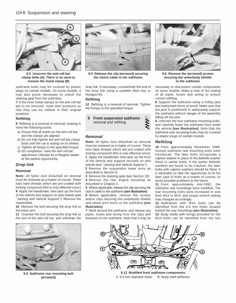
subframe bolts may be covered by plasticplugs on certain models. On some models, itmay also prove necessary to unbolt thesteering gear from the subframe.7 If the inner metal clamps on the anti-roll barare to be removed, mark their positions sothat they can be refitted in their originalpositions.
Refitting8 Refitting is a reversal of removal, bearing inmind the following points.a) Ensure that all marks on the anti-roll bar
and the clamps are aligned.b) Do not fully tighten the anti-roll bar clamp
bolts until the car is resting on its wheels.c) Tighten all fixings to the specified torque.d) On completion, have the anti-roll bar
adjustment checked by a Peugeot dealerat the earliest opportunity.
Drop link
RemovalNote: All Nyloc nuts disturbed on removalmust be renewed as a matter of course. Thesenuts have threads which are pre-coated withlocking compound (this is only effective once.)9 Apply the handbrake, then jack up the frontof the vehicle and support on axle stands (see“Jacking and Vehicle Support”). Remove theroadwheels.10 Remove the bolt securing the drop link tothe lower arm.11 Unscrew the bolt securing the drop link tothe end of the anti-roll bar, and withdraw the
drop link. If necessary, counterhold the end ofthe drop link using a suitable Allen key orhexagon bit.
Refitting12 Refitting is a reversal of removal. Tightenthe fixings to the specified torque.
9 Front suspension subframe -removal and refitting 4
RemovalNote: All Nyloc nuts disturbed on removalmust be renewed as a matter of course. Thesenuts have threads which are pre-coated withlocking compound (this is only effective once).1 Apply the handbrake, then jack up the frontof the vehicle and support securely on axlestands (see “Jacking and Vehicle Support”).2 Remove the suspension lower arms asdescribed in Section 6.3 Remove the steering gear (see Section 19).4 Remove the rear engine mounting asdescribed in Chapter 2.5 Where applicable, release the clip securing theclutch cable to the subframe (see illustration).6 Where applicable, remove the screwsand/or clips securing the underbody shieldsand wheel arch liners to the subframe (seeillustration).7 Work around the subframe, and release anypipes, hoses and wiring from the clips andbrackets on the subframe. Note that it may be
necessary to disconnect certain componentson some models. Make a note of the routingof all pipes, hoses and wiring to ensurecorrect refitting.8 Support the subframe using a trolley jackand interposed block of wood. Make sure thatthe jack is positioned to adequately supportthe subframe without danger of the assemblyfalling off the jack.9 Unscrew the four subframe mounting bolts,and carefully lower the subframe from underthe vehicle (see illustration). Note that thesubframe rear mounting bolts may be coveredby plastic plugs on certain models.
Refitting10 From approximately November 1988,revised subframe rear mounting bolts wereintroduced. The later bolts incorporate acaptive washer in place of the Bellville washerfitted to earlier bolts. If the earlier Bellvillewashers are found to be cracked, the laterbolts with captive washers should be fitted. Itis advisable to take the opportunity to fit thelater type of bolts as a matter of course, toavoid possible problems in the future.11 From approximately mid-1992, thesubframe rear mountings were modified. Therear mounting bolts were increased in sizefrom M12 to M14, and torque wrench settingwas changed accordingly.12 Subframes with M14 bolts can beidentified from the 6.0 mm holes locatedbehind the rear mountings (see illustration).13 Body shells with fixings provided for theM14 bolts can be identified from the two
10•8 Suspension and steering
8.5 Unscrew the anti-roll bar clamp bolts (A). There is no need to
remove the metal clamp (B)
9.6 Remove the (arrowed) screwssecuring the underbody shields
to the subframe
9.12 Modified front subframe components9.9 Subframe rear mounting bolt (arrowed)
9.5 Release the clip (arrowed) securingthe clutch cable to the subframe
A 6.0 mm diameter holes B Body shell stiffeners

stiffeners located under the floor (seeillustration 9.12).14 A few vehicles were fitted with the earlierbody shells (with M12 bolt holes and nostiffeners), and the later subframe (with M14bolt holes and 6.0 mm identification holes).On these models, the subframe is securedwith special M12 shouldered bolts.15 If either the subframe or the body shell arerenewed, carry out the action given in thetable below, according to the type ofcomponents fitted. Use only the specifiedparts, available from a Peugeot dealer.16 Further refitting is a reversal of removal,bearing in mind the following points.a) Clean the threads of the subframe
mounting bolts, and apply thread-lockingcompound before refitting.
b) Refit the rear engine mounting withreference to Chapter 2.
c) Refit the steering gear (see Section 19).d) Refit the lower arms with reference to
Section 6.e) Tighten all fixings to the specified torque.
10 Rear hub assembly - removal and refitting 4
RemovalNote: Do not remove the hub assembly unlessit is absolutely necessary. A puller will be
required to draw the hub assembly off thestub axle, and the hub bearing will almostcertainly be damaged by the removalprocedure. A new oil seal support cup, and anew hub nut and hub cap will be required onrefitting.1 On models with rear disc brakes, removethe brake disc as described in Chapter 9.2 On models with rear drum brakes, removethe brake drum as described in Chapter 9. Ifdesired, to improve access for hub removal,also remove the brake shoes.3 Where applicable, remove the ABS wheelsensor as described in Chapter 9. Note thatthere is no need to disconnect the wiringconnector, but move the sensor to one side,clear of the working area.4 Using a hammer and a large flat-bladedscrewdriver, carefully tap and prise the capout of the centre of the hub. Discard the cap -
Suspension and steering 10•9
10.6a Using a puller to draw the rear hubassembly from the stub axle
10.6c . . . and the oil seal support cup10.6b Removing the inner bearing race . . .
10.4b . . . then tap up the staking on thehub nut
10.4a Tap the cap from the centre of the hub . . .
10
Front subframe parts compatibility table - see Section 9
New parts fitted Parts not renewed Action to be taken Bolt dia.
Body shell with Subframe with Discard M14 cage M14 subframe fixings M12 mounting bolt holes nuts fitted to body shell
(accessible from inside body shell), and fit M12 cage nuts M12
Subframe with Body shell with Discard the subframe M14 mounting bolt holes M12 subframe fixings rear mounting bolts and fit
special M12 shouldered bolts M12Subframe with M14 mounting bolt holes, and body shell with None Fit M14 bolts withM14 subframe fixings plastic protectors M14
a new one must be used on refitting. Using ahammer and a chisel-nosed tool, tap up thestaking securing the hub retaining nut to thegroove in the stub axle (see illustrations).5 Using a socket and long bar, slacken andremove the rear hub nut, and withdraw thethrustwasher. Discard the hub nut - a new nutmust used on refitting.6 Using a puller, draw the hub assembly offthe stub axle, along with the outer bearingrace. With the hub removed, use the puller todraw the inner bearing race off the stub axle,then remove the oil seal support cup, notingwhich way around it is fitted (seeillustrations).7 Refit the races to the hub bearing, andcheck the hub bearing for signs of roughness.It is recommended that the bearing should berenewed as a matter of course, as it is likely tohave been damaged during removal. Thismeans that the complete hub assembly mustbe renewed, since it is not possible to obtainthe bearing separately.8 With the hub removed, examine the stubaxle shaft for signs of wear or damage. Thestub axle is integral with the trailing arms, andif damaged, the complete assembly must berenewed.
Refitting9 Lubricate the stub axle shaft with cleanengine oil, then slide on the new oil sealsupport cup, ensuring it is fitted the correctway round.10 Fit the new bearing inner race, and tap itfully onto the stub axle using a hammer and atubular drift which bears only on the flat insideedge of the race (see Tool Tip overleaf).
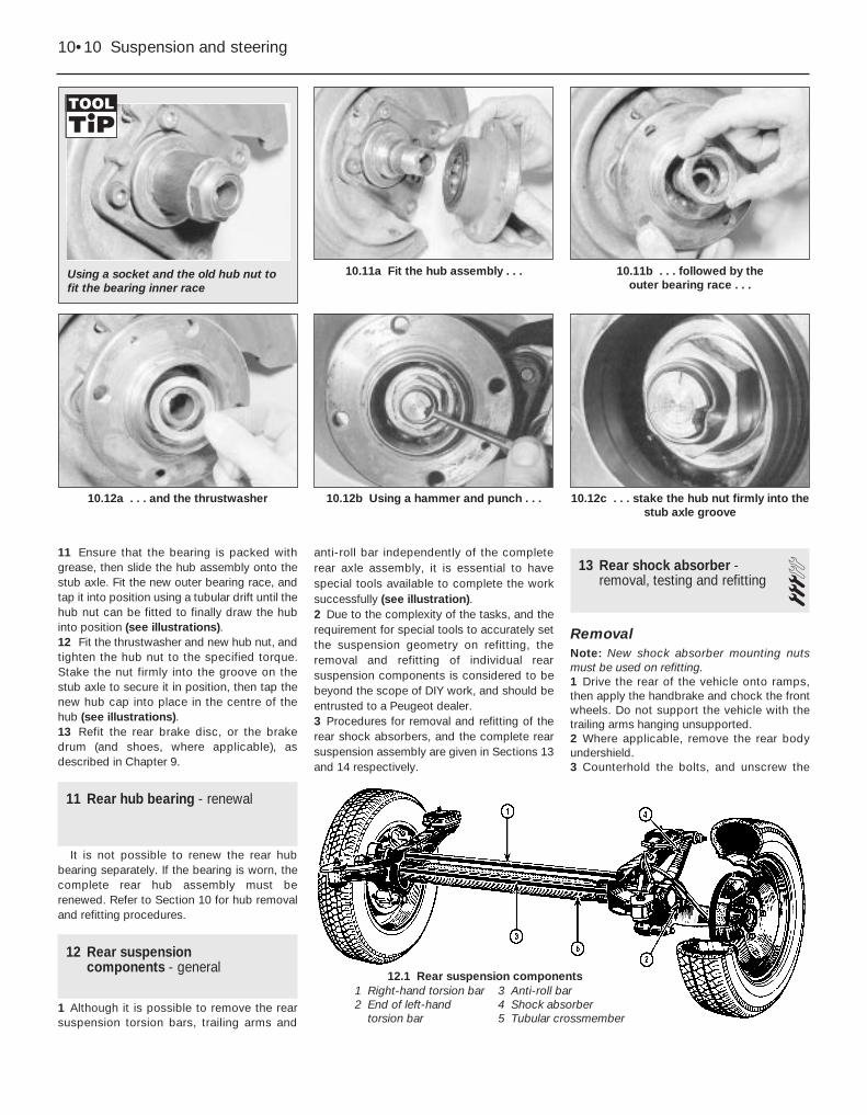
11 Ensure that the bearing is packed withgrease, then slide the hub assembly onto thestub axle. Fit the new outer bearing race, andtap it into position using a tubular drift until thehub nut can be fitted to finally draw the hubinto position (see illustrations).12 Fit the thrustwasher and new hub nut, andtighten the hub nut to the specified torque.Stake the nut firmly into the groove on thestub axle to secure it in position, then tap thenew hub cap into place in the centre of thehub (see illustrations).13 Refit the rear brake disc, or the brakedrum (and shoes, where applicable), asdescribed in Chapter 9.
11 Rear hub bearing - renewal
It is not possible to renew the rear hubbearing separately. If the bearing is worn, thecomplete rear hub assembly must berenewed. Refer to Section 10 for hub removaland refitting procedures.
12 Rear suspensioncomponents - general
1 Although it is possible to remove the rearsuspension torsion bars, trailing arms and
anti-roll bar independently of the completerear axle assembly, it is essential to havespecial tools available to complete the worksuccessfully (see illustration).2 Due to the complexity of the tasks, and therequirement for special tools to accurately setthe suspension geometry on refitting, theremoval and refitting of individual rearsuspension components is considered to bebeyond the scope of DIY work, and should beentrusted to a Peugeot dealer.3 Procedures for removal and refitting of therear shock absorbers, and the complete rearsuspension assembly are given in Sections 13and 14 respectively.
13 Rear shock absorber -removal, testing and refitting 3
RemovalNote: New shock absorber mounting nutsmust be used on refitting.1 Drive the rear of the vehicle onto ramps,then apply the handbrake and chock the frontwheels. Do not support the vehicle with thetrailing arms hanging unsupported.2 Where applicable, remove the rear bodyundershield.3 Counterhold the bolts, and unscrew the
10•10 Suspension and steering
10.11b . . . followed by the outer bearing race . . .
10.12c . . . stake the hub nut firmly into thestub axle groove
10.12b Using a hammer and punch . . .10.12a . . . and the thrustwasher
10.11a Fit the hub assembly . . .Using a socket and the old hub nut tofit the bearing inner race
1 Right-hand torsion bar2 End of left-hand
torsion bar
3 Anti-roll bar4 Shock absorber5 Tubular crossmember
12.1 Rear suspension components

shock absorber upper and lower securingnuts. Recover the washers (see illustration).4 Tap the bolts from the mountings to free theshock absorber, then withdraw the unit fromunder the vehicle.
Testing5 Examine the shock absorber for signs offluid leakage or damage. Test the operation ofthe shock absorber, while holding it in anupright position, by moving the piston througha full stroke and then through short strokes of50 to 100 mm. In both cases, the resistancefelt should be smooth and continuous. If theresistance is jerky, or uneven, or if there is anyvisible sign of wear or damage, renewal isnecessary.6 Also check the rubber mounting bushes fordamage and deterioration. New bushes canbe fitted using a long bolt, nut and spacers todraw the bush into position. Lubricate the newbush with soapy water to aid fitting.7 Inspect the shanks of the mounting boltsfor signs of wear or damage, and renew asnecessary.
Refitting8 Prior to refitting the shock absorber, mountit upright in the vice, and operate it fullythrough several strokes in order to prime it.Apply a smear of multi-purpose grease toboth the shock absorber mounting bolts.9 Manoeuvre the shock absorber intoposition, and insert its mounting bolts (withwashers in place). Note that the bolts fit fromthe inside of the vehicle, ie the nuts fit on theroadwheel side of the shock absorber.10 Fit the washers and new nuts to themounting bolts, but do not tighten the fixingsat this stage.11 Measure the distance between the shockabsorber bolt centres, and load the vehicle (byadding weight to the luggage compartment)until a distance of 328.0 mm is obtainedbetween the bolt centres. Tighten the shockabsorber mounting nuts and bolts to thespecified torque.12 Drive the vehicle off the ramps.
14 Rear axle assembly - removal and refitting 4
RemovalNote: Before carrying out this procedure, it isadvisable to run the fuel tank as near empty aspossible to minimise the amount of fuel whichhas to be drained from the tank.1 Chock the front wheels, then jack up therear of the vehicle and support securely onaxle stands, until the trailing arms are atmaximum extension, with the roadwheels stillresting on the ground (see “Jacking andVehicle Support”).2 Where applicable, remove the rearunderbody shield.3 Remove the rear and intermediate exhaustsections as described in Chapter 4.4 Empty the fuel tank by either disconnectingthe filler pipe and draining, or by siphoning thefuel out through the filler neck. In either case,collect the fuel in a container which can besealed.5 Disconnect the fuel filler pipe from the tank(If not already done). Plug the open ends ofthe tank and the hose to prevent dirt ingress.6 Remove the rear exhaust heat shield fromthe underbody.7 Disconnect the handbrake cables from theadjuster mechanism under the rearunderbody, with reference to Chapter 9.8 Release the handbrake cables from anyclips and brackets, and move them clear ofthe suspension components to facilitateremoval.9 Loosen the fuel tank support strap bolts asfar as possible without removing them, andlower the fuel tank.10 Disconnect the brake fluid pipes at theunions on the rear suspension assembly, withreference to Chapter 9. Plug the open ends ofthe unions.11 On models with a load-sensitive rearbrake pressure regulating valve, disconnectthe hydraulic pipes at the valve. Again, plugthe opens ends of the pipes and the valve.12 Where applicable, remove the rear ABSwheel sensors. Note that there is no need to
disconnect the wiring connectors, but unclipthe wiring harnesses from the rear suspensioncomponents, and move the sensors to oneside, clear of the working area.13 Place a trolley jack under the rearsuspension tubular crossmember to supportthe suspension assembly.14 Make a final check to ensure that allrelevant pipes and wires have beendisconnected to facilitate removal of thesuspension assembly.15 Using a long-reach splined adapter,unscrew the suspension assembly rearsecuring bolts, accessible through the holesin the suspension assembly side members(see illustration).16 Working at the front of the suspensionassembly, unscrew the two bolts on each sidesecuring the front mountings to theunderbody (see illustration).17 Lower the trolley jack slightly, and pull thesuspension rearwards. If necessary, raise thevehicle body in order for the suspension toclear the fuel tank, then withdraw thesuspension assembly from under the vehicle.
Refitting18 Refitting is a reversal of the removalprocedure, bearing in mind the followingpoints.a) Tighten all fixings to the specified torque.b) Bleed the brake hydraulic system as
described in Chapter 9.c) Adjust the handbrake mechanism as
described in Chapter 9.d) On completion, have the rear ride height
checked by a Peugeot dealer.
15 Vehicle ride height - checking 5Checking of the vehicle ride height requires
the use of Peugeot special tools to accuratelycompress the suspension in a suspensionchecking bay.
The operation should be entrusted to aPeugeot dealer, as it not possible to carry outchecking accurately without the use of theappropriate tools.
Suspension and steering 10•11
14.16 Unscrew the two bolts (arrowed) oneach side securing the suspension
mountings to the body
14.15 Using a long-reach splined adapterto unscrew a suspension assembly
rear securing bolt
13.3 Rear shock absorber upper mounting bolt (arrowed)
10

16 Steering wheel - removal and refitting 2
Models without air bagRemovalNote: A new securing nut and washer must beused on refitting.1 Position the front wheel in the straight-ahead position.2 Prise out the centre trim from the steeringwheel.3 Make alignment marks between the end ofthe steering column shaft and the steeringwheel boss.4 Using a long-reach socket and extensionbar, unscrew the steering wheel securing nutby a few turns (see illustration).5 Using the palms of the hands, strike theunderside of the steering wheel firmly torelease the wheel from the column splines.6 Remove the securing nut, and lift off thesteering wheel.
Refitting7 Refitting is a reversal of removal, but alignthe marks made before removal, fit a newwasher, and tighten the new securing nut tothe specified torque.
Models with air bag
a) Do not drop the steering wheel, or subjectit to impacts.
b) Do not attempt to dismantle the steeringwheel.
c) Do not attempt to fit a steering wheelfrom another model of vehicle (even adifferent model of Peugeot 405), as the airbag control module is calibrated for eachparticular model.
RemovalNote: A new securing nut and washer must beused on refitting.8 Remove the air bag unit (see Chapter 12).
9 Set the front wheels in the straight-aheadposition, and engage the steering lock.10 Make alignment marks between the endof the steering column shaft and the steeringwheel boss.11 Unscrew the steering wheel retaining nutby several threads.12 Using the palms of the hands, strike theunderside of the steering wheel firmly torelease the wheel from the column splines.13 Separate the two halves of the air bagcontrol unit wiring connector.14 Remove the steering wheel retaining nut,and recover the washer.15 Carefully withdraw the steering wheel,feeding the wiring harness (connecting therotary connector to the air bag control unit)through the wheel as it is withdrawn. Do notdisturb the air bag control unit wiringconnector (located in the steering wheel).
Refitting16 Refitting is a reversal of removal, bearingin mind the following points.a) Align the marks made before removal.b) Fit a new washer, and tighten the new nut
to the specified torque.c) Refit the air bag unit (see Chapter 12).
17 Steering column - removal,inspection and refitting 3
Removal1 Disconnect the battery negative lead.
2 Where applicable, remove the air bag asdescribed in Chapter 12.3 Remove the steering wheel (see Section 16).4 Remove the steering column shrouds withreference to Chapter 11.5 Remove the steering column stalk switchesas described in Chapter 12.6 On models up the 1992, release thesecuring clips, and lower the fusebox panelfrom the facia.7 Working in the footwell, unclip the carpettrim panel from under the facia for access tothe steering column pinch-bolt.8 Working under the steering column,disconnect the three ignition switch wiringconnectors (see illustration). Similarly, whereapplicable disconnect the air bag wiringharness connector.9 Working in the driver’s footwell, makealignment marks on the intermediate shaftand the steering column shaft to aid refitting.10 Unscrew the clamp bolt securing thesteering column shaft to the intermediateshaft (see illustration).11 Unscrew the two lower steering columnsecuring nuts (models up to 1992) or bolts(models from 1993) (see illustration).12 Unscrew the upper steering columnsecuring nuts, then withdraw the steeringcolumn from the vehicle (see illustration).13 To remove the intermediate shaft, with thesteering column removed, proceed as follows.a) Working in the engine compartment,
unscrew the shaft-to-steering gear pinionpinch-bolt.
b) Withdraw the shaft through the bulkheadgrommet into the vehicle interior.
10•12 Suspension and steering
16.4 Unscrewing the steering wheel nut
17.10 Unscrewing the steering columnshaft-to intermediate shaft clamp bolt
17.12 Steering column upper securingnuts (arrowed) - models up to 1992
17.11 Lower steering column securingnuts (arrowed) - models from 1993
17.8 Ignition switch wiring connectors(arrowed) - models from 1993
Warning: Refer to theprecautions given in Chapter 12,Section 24 before proceeding.Note that the air bag control
module is integral with the steering wheel.Additionally, note the following points.
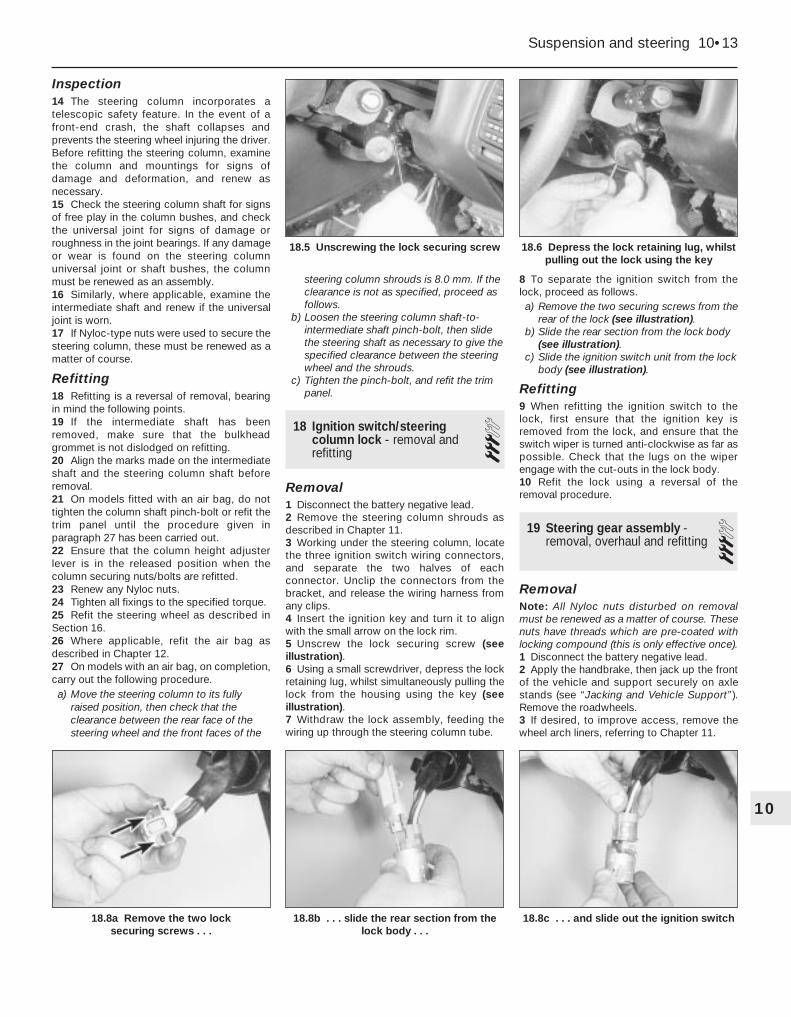
Inspection14 The steering column incorporates atelescopic safety feature. In the event of afront-end crash, the shaft collapses andprevents the steering wheel injuring the driver.Before refitting the steering column, examinethe column and mountings for signs ofdamage and deformation, and renew asnecessary.15 Check the steering column shaft for signsof free play in the column bushes, and checkthe universal joint for signs of damage orroughness in the joint bearings. If any damageor wear is found on the steering columnuniversal joint or shaft bushes, the columnmust be renewed as an assembly.16 Similarly, where applicable, examine theintermediate shaft and renew if the universaljoint is worn.17 If Nyloc-type nuts were used to secure thesteering column, these must be renewed as amatter of course.
Refitting18 Refitting is a reversal of removal, bearingin mind the following points.19 If the intermediate shaft has beenremoved, make sure that the bulkheadgrommet is not dislodged on refitting.20 Align the marks made on the intermediateshaft and the steering column shaft beforeremoval.21 On models fitted with an air bag, do nottighten the column shaft pinch-bolt or refit thetrim panel until the procedure given inparagraph 27 has been carried out.22 Ensure that the column height adjusterlever is in the released position when thecolumn securing nuts/bolts are refitted.23 Renew any Nyloc nuts.24 Tighten all fixings to the specified torque.25 Refit the steering wheel as described inSection 16.26 Where applicable, refit the air bag asdescribed in Chapter 12.27 On models with an air bag, on completion,carry out the following procedure.a) Move the steering column to its fully
raised position, then check that theclearance between the rear face of thesteering wheel and the front faces of the
steering column shrouds is 8.0 mm. If theclearance is not as specified, proceed asfollows.
b) Loosen the steering column shaft-to-intermediate shaft pinch-bolt, then slidethe steering shaft as necessary to give thespecified clearance between the steeringwheel and the shrouds.
c) Tighten the pinch-bolt, and refit the trimpanel.
18 Ignition switch/steeringcolumn lock - removal andrefitting
3Removal1 Disconnect the battery negative lead.2 Remove the steering column shrouds asdescribed in Chapter 11.3 Working under the steering column, locatethe three ignition switch wiring connectors,and separate the two halves of eachconnector. Unclip the connectors from thebracket, and release the wiring harness fromany clips.4 Insert the ignition key and turn it to alignwith the small arrow on the lock rim.5 Unscrew the lock securing screw (seeillustration).6 Using a small screwdriver, depress the lockretaining lug, whilst simultaneously pulling thelock from the housing using the key (seeillustration).7 Withdraw the lock assembly, feeding thewiring up through the steering column tube.
8 To separate the ignition switch from thelock, proceed as follows.a) Remove the two securing screws from the
rear of the lock (see illustration).b) Slide the rear section from the lock body
(see illustration).c) Slide the ignition switch unit from the lock
body (see illustration).
Refitting9 When refitting the ignition switch to thelock, first ensure that the ignition key isremoved from the lock, and ensure that theswitch wiper is turned anti-clockwise as far aspossible. Check that the lugs on the wiperengage with the cut-outs in the lock body.10 Refit the lock using a reversal of theremoval procedure.
19 Steering gear assembly -removal, overhaul and refitting 3
RemovalNote: All Nyloc nuts disturbed on removalmust be renewed as a matter of course. Thesenuts have threads which are pre-coated withlocking compound (this is only effective once).1 Disconnect the battery negative lead.2 Apply the handbrake, then jack up the frontof the vehicle and support securely on axlestands (see “Jacking and Vehicle Support”).Remove the roadwheels.3 If desired, to improve access, remove thewheel arch liners, referring to Chapter 11.
Suspension and steering 10•13
18.8a Remove the two lock securing screws . . .
18.8c . . . and slide out the ignition switch18.8b . . . slide the rear section from thelock body . . .
18.6 Depress the lock retaining lug, whilstpulling out the lock using the key
18.5 Unscrewing the lock securing screw
10

4 On models with power steering, drain thehydraulic fluid as follows.a) Remove the cap from the fluid reservoir.b) Place a container under the high pressure
fluid pipe union on the steering gear, thenunscrew the union.
c) Allow the fluid to drain into the container.d) Turn the steering from lock-to-lock
several times to completely drain thesystem.
e) Disconnect the low pressure hose fromthe steering gear.
5 Where applicable, unbolt the heat shieldfrom the steering gear.6 On manual gearbox models, prise the capfrom the gear linkage pivot, then unscrew thelinkage pivot bolt. Move the gear linkage clearof the steering gear, and tie it up out of theway using wire or string.7 Make alignment marks between the end ofthe intermediate shaft and the steering gearpinion, then unscrew the clamp bolt securingthe intermediate shaft universal joint to thepinion.8 Working on one side of the vehicle, slackenand partially unscrew the track rod end nut(unscrew the nut as far as the end of thethreads on the balljoint to prevent damage tothe threads as the joint is released), thenrelease the balljoint using a balljoint separatortool (see illustration). Remove the nut.9 Repeat the procedure on the remaining sideof the vehicle.10 Unscrew the two bolts securing thesteering gear to the subframe. Recover thewashers, and spacers, taking careful note oftheir positions to ensure correct refitting.11 Rotate the steering gear around itshorizontal axis, so that the pinion is at thebottom, then withdraw the assembly fromunder the right-hand wheel arch.
Overhaul12 Examine the steering gear assembly forsigns of wear or damage, and check that therack moves freely throughout the full length ofits travel, with no signs of roughness orexcessive free play between the steering gearpinion and rack. It is possible to overhaul thesteering gear assembly housing components,but this task should be entrusted to a Peugeotdealer. The only components which can berenewed easily by the home mechanic are the
steering gear gaiters, the track rod balljointsand the track rods. Track rod, track rodballjoint and steering gear gaiter renewalprocedures are covered in Sections 24, 23and 20 respectively.13 On models with power steering, inspectall the steering gear fluid unions for signs ofleakage, and check that all union nuts aresecurely tightened. Also examine the steeringgear hydraulic ram for signs of fluid leakage ordamage, and if necessary renew it.
RefittingNote: There have been a number ofmodifications to the steering gear and thesubframe, which alter the dimension of thesteering gear-to-subframe mounting points.Different thicknesses of spacer are fittedbetween the rack and the subframe, andunder the mounting bolt heads. Due to themany combinations of different components,and the non-interchangeability of the differentcomponents, if either the steering gear orsubframe are to be renewed, the advice of aPeugeot dealer should be sought.14 Refitting is a reversal of removal, bearingin mind the following points.a) Use new nuts when reconnecting the
track rod ends.b) Tighten all fixings to the specified torque.c) On models with power steering, fill and
bleed the hydraulic system as describedin Section 21.
d) On completion, have the front wheelalignment checked at the earliestopportunity.
20 Steering gear rubber gaiters - renewal 4
Manual steering gear1 Remove the track rod balljoint as describedin Section 23.2 Mark the correct fitted position of the gaiteron the track rod, then release the retainingclips and slide the gaiter off the steering gearhousing and track rod end.3 Thoroughly clean the track rod and thesteering gear housing, using fine abrasivepaper to polish off any corrosion, burrs orsharp edges, which might damage the newgaiter’s sealing lips on installation. Scrape offall the grease from the old gaiter, and apply itto the track rod inner balljoint. (This assumesthat grease has not been lost or contaminatedas a result of damage to the old gaiter. Usefresh grease if in doubt.)4 Carefully slide the new gaiter onto the trackrod end, and locate it on the steering gearhousing. Align the outer edge of the gaiterwith the mark made on the track rod prior toremoval, then secure it in position with newretaining clips.5 Refit the track rod balljoint as described inSection 23.
Power-assisted steering gear6 On power-assisted steering gear assem-blies, it is only possible to renew the gaiternearest the drive pinion, ie the right-handgaiter on right-hand-drive models, and theleft-hand gaiter on left-hand-drive models.This can be renewed as described above inparagraphs 1 to 5.7 The task of renewing the opposite gaitershould be entrusted to a Peugeot dealer. Thisis necessary since it is not possible to passthe gaiter over the steering rack stud to whichthe hydraulic ram is fixed. Therefore, thesteering gear must be dismantled and therack removed from the housing to allow thegaiter to be renewed.8 The only task on this end of the assemblywhich can be carried out by the homemechanic is the renewal of the track rod innerballjoint dust cover. The dust cover can berenewed once the track rod balljoint has beenremoved as described in Section 23. Onrefitting, ensure that the dust cover iscorrectly located on the track rod and steeringrack, then refit the balljoint.
21 Power steering system -bleeding 2
1 This procedure will only be necessary whenany part of the hydraulic system has beendisconnected.2 Referring to Chapter 1, remove the fluidreservoir filler cap, and top-up with thespecified fluid to the maximum level mark.3 With the engine stopped, slowly move thesteering from lock-to-lock several times topurge out the trapped air, then top-up thelevel in the fluid reservoir. Repeat thisprocedure until the fluid level in the reservoirdoes not drop any further.4 Start the engine, then slowly move thesteering from lock-to-lock several times topurge out any remaining air in the system.Repeat this procedure until bubbles cease toappear in the fluid reservoir.5 If, when turning the steering, an abnormalnoise is heard from the fluid lines, it indicatesthat there is still air in the system. Check thisby turning the wheels to the straight-aheadposition and switching off the engine. If thefluid level in the reservoir rises, then air ispresent in the system, and further bleeding isnecessary.6 Once all traces of air have been removedfrom the power steering hydraulic system,turn the engine off and allow the system tocool. Once cool, check that fluid level is up tothe maximum mark on the power steeringfluid reservoir, topping-up if necessary (referto “Weekly Checks” if necessary).
10•14 Suspension and steering
19.8 Using a balljoint separator tool todisconnect the track rod end balljoint
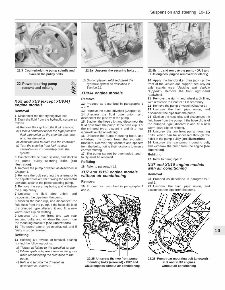
22 Power steering pump -removal and refitting 3
XU5 and XU9 (except XU9J4)engine models
Removal1 Disconnect the battery negative lead.2 Drain the fluid from the hydraulic system asfollows.a) Remove the cap from the fluid reservoir.b) Place a container under the high pressure
fluid pipe union on the steering gear, thenunscrew the union.
c) Allow the fluid to drain into the container.d) Turn the steering from lock-to-lock
several times to completely drain thesystem.
3 Counterhold the pump spindle, and slackenthe pump pulley securing bolts (seeillustration).4 Remove the pump drivebelt as described inChapter 1.5 Remove the bolt securing the alternator tothe adjuster bracket, then swing the alternatorupwards, clear of the power steering pump.6 Remove the securing bolts, and withdrawthe pump pulley.7 Unscrew the fluid pipe union, anddisconnect the pipe from the pump.8 Slacken the hose clip, and disconnect thefluid hose from the pump. If the hose clip is ofthe crimped type, discard it and fit a newworm-drive clip on refitting.9 Unscrew the two front and two rearsecuring bolts, and withdraw the pump fromthe mounting brackets (see illustrations).10 The pump cannot be overhauled, and iffaulty must be renewed.
Refitting11 Refitting is a reversal of removal, bearingin mind the following points.a) Tighten all fixings to the specified torque.b) Where applicable, use a new securing clip
when reconnecting the fluid hose to thepump.
c) Refit and tension the drivebelt asdescribed in Chapter 1.
d) On completion, refill and bleed thehydraulic system as described in Section 21.
XU9J4 engine models
Removal12 Proceed as described in paragraphs 1and 2.13 Remove the pump drivebelt (Chapter 1).14 Unscrew the fluid pipe union, anddisconnect the pipe from the pump.15 Slacken the hose clip, and disconnect thefluid hose from the pump. If the hose clip is ofthe crimped type, discard it and fit a newworm-drive clip on refitting.16 Unscrew the pump mounting bolts, andwithdraw the pump from the mountingbrackets. Recover any washers and spacersfrom the bolts, noting their locations to ensurecorrect refitting.17 The pump cannot be overhauled, and iffaulty must be renewed.
Refitting18 Refer to paragraph 11.
XU7 and XU10 engine modelswithout air conditioning
Removal19 Proceed as described in paragraphs 1and 2.
20 Apply the handbrake, then jack up thefront of the vehicle and support securely onaxle stands (see “Jacking and VehicleSupport”). Remove the front right-handroadwheel.21 Remove the right-hand wheel arch liner,with reference to Chapter 11 if necessary.22 Remove the pump drivebelt (Chapter 1).23 Unscrew the fluid pipe union, anddisconnect the pipe from the pump.24 Slacken the hose clip, and disconnect thefluid hose from the pump. If the hose clip is ofthe crimped type, discard it and fit a newworm-drive clip on refitting.25 Unscrew the two front pump mountingbolts, which can be accessed through theholes in the pump pulley (see illustration).26 Unscrew the rear pump mounting bolt,and withdraw the pump from the engine (seeillustration).
Refitting27 Refer to paragraph 11.
XU7 and XU10 engine modelswith air conditioning
Removal28 Proceed as described in paragraphs 1and 2.29 Unscrew the fluid pipe union, anddisconnect the pipe from the pump.
Suspension and steering 10•15
22.9b . . . and remove the pump - XU5 andXU9 engines (engine removed for clarity)
22.26 Pump rear mounting bolt (arrowed) -XU7 and XU10 engines without air conditioning
22.25 Unscrew the two front pumpmounting bolts (arrowed) - XU7 and
XU10 engines without air conditioning
22.9a Unscrew the securing bolts . . .22.3 Counterhold the pump spindle andslacken the pulley bolts
10
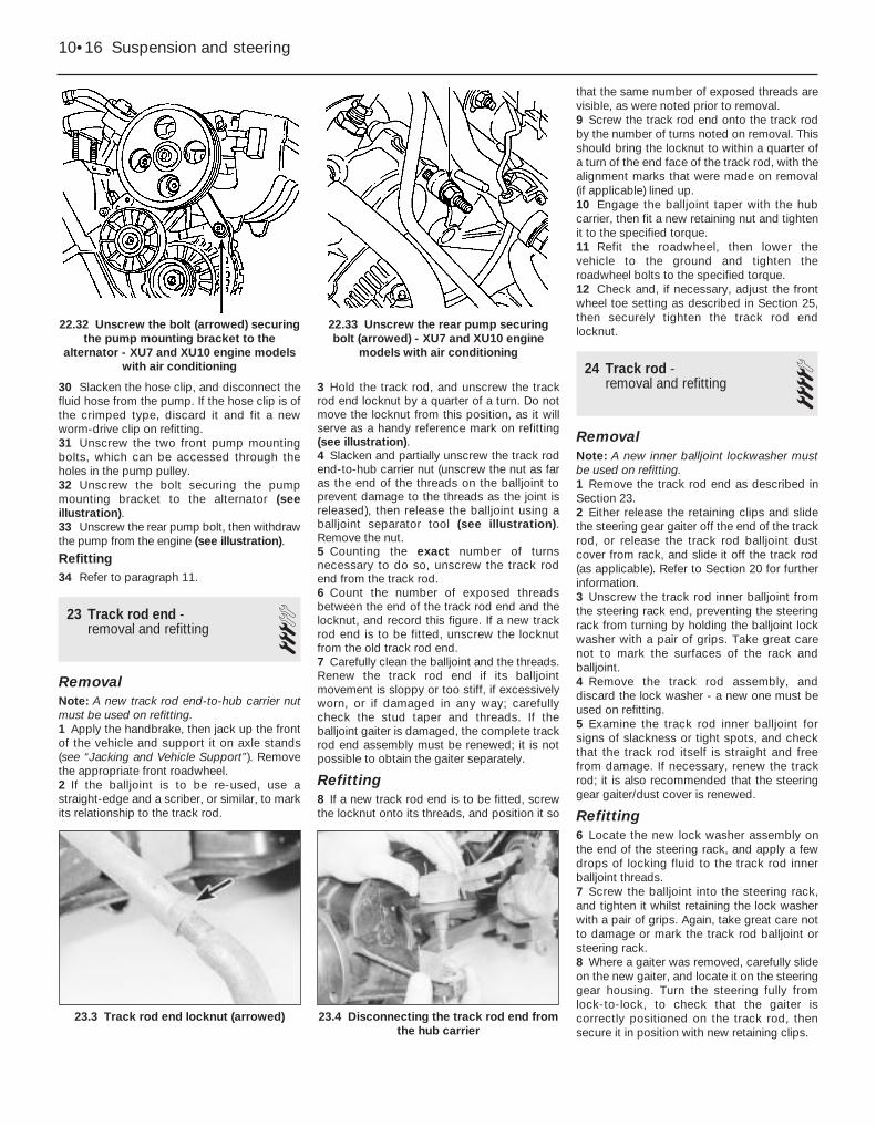
30 Slacken the hose clip, and disconnect thefluid hose from the pump. If the hose clip is ofthe crimped type, discard it and fit a newworm-drive clip on refitting.31 Unscrew the two front pump mountingbolts, which can be accessed through theholes in the pump pulley.32 Unscrew the bolt securing the pumpmounting bracket to the alternator (seeillustration).33 Unscrew the rear pump bolt, then withdrawthe pump from the engine (see illustration).
Refitting34 Refer to paragraph 11.
23 Track rod end - removal and refitting 3
RemovalNote: A new track rod end-to-hub carrier nutmust be used on refitting.1 Apply the handbrake, then jack up the frontof the vehicle and support it on axle stands(see “Jacking and Vehicle Support”). Removethe appropriate front roadwheel.2 If the balljoint is to be re-used, use astraight-edge and a scriber, or similar, to markits relationship to the track rod.
3 Hold the track rod, and unscrew the trackrod end locknut by a quarter of a turn. Do notmove the locknut from this position, as it willserve as a handy reference mark on refitting(see illustration).4 Slacken and partially unscrew the track rodend-to-hub carrier nut (unscrew the nut as faras the end of the threads on the balljoint toprevent damage to the threads as the joint isreleased), then release the balljoint using aballjoint separator tool (see illustration).Remove the nut.5 Counting the exact number of turnsnecessary to do so, unscrew the track rodend from the track rod.6 Count the number of exposed threadsbetween the end of the track rod end and thelocknut, and record this figure. If a new trackrod end is to be fitted, unscrew the locknutfrom the old track rod end.7 Carefully clean the balljoint and the threads.Renew the track rod end if its balljointmovement is sloppy or too stiff, if excessivelyworn, or if damaged in any way; carefullycheck the stud taper and threads. If theballjoint gaiter is damaged, the complete trackrod end assembly must be renewed; it is notpossible to obtain the gaiter separately.
Refitting8 If a new track rod end is to be fitted, screwthe locknut onto its threads, and position it so
that the same number of exposed threads arevisible, as were noted prior to removal.9 Screw the track rod end onto the track rodby the number of turns noted on removal. Thisshould bring the locknut to within a quarter ofa turn of the end face of the track rod, with thealignment marks that were made on removal(if applicable) lined up.10 Engage the balljoint taper with the hubcarrier, then fit a new retaining nut and tightenit to the specified torque.11 Refit the roadwheel, then lower thevehicle to the ground and tighten theroadwheel bolts to the specified torque.12 Check and, if necessary, adjust the frontwheel toe setting as described in Section 25,then securely tighten the track rod endlocknut.
24 Track rod - removal and refitting 4
RemovalNote: A new inner balljoint lockwasher mustbe used on refitting.1 Remove the track rod end as described inSection 23.2 Either release the retaining clips and slidethe steering gear gaiter off the end of the trackrod, or release the track rod balljoint dustcover from rack, and slide it off the track rod(as applicable). Refer to Section 20 for furtherinformation.3 Unscrew the track rod inner balljoint fromthe steering rack end, preventing the steeringrack from turning by holding the balljoint lockwasher with a pair of grips. Take great carenot to mark the surfaces of the rack andballjoint.4 Remove the track rod assembly, anddiscard the lock washer - a new one must beused on refitting.5 Examine the track rod inner balljoint forsigns of slackness or tight spots, and checkthat the track rod itself is straight and freefrom damage. If necessary, renew the trackrod; it is also recommended that the steeringgear gaiter/dust cover is renewed.
Refitting6 Locate the new lock washer assembly onthe end of the steering rack, and apply a fewdrops of locking fluid to the track rod innerballjoint threads.7 Screw the balljoint into the steering rack,and tighten it whilst retaining the lock washerwith a pair of grips. Again, take great care notto damage or mark the track rod balljoint orsteering rack.8 Where a gaiter was removed, carefully slideon the new gaiter, and locate it on the steeringgear housing. Turn the steering fully fromlock-to-lock, to check that the gaiter iscorrectly positioned on the track rod, thensecure it in position with new retaining clips.
10•16 Suspension and steering
22.32 Unscrew the bolt (arrowed) securingthe pump mounting bracket to the
alternator - XU7 and XU10 engine modelswith air conditioning
23.3 Track rod end locknut (arrowed) 23.4 Disconnecting the track rod end fromthe hub carrier
22.33 Unscrew the rear pump securingbolt (arrowed) - XU7 and XU10 engine
models with air conditioning

9 Where a dust cover was removed, carefullyslide on the new cover, and locate it in itsgrooves on the steering rack collar and trackrod.
25 Wheel alignment andsteering angles - generalinformation
General1 A car’s steering and suspension geometryis defined in four basic settings - all angles areexpressed in degrees (toe settings are alsoexpressed as a measurement); the relevantsettings are camber, castor, steering axisinclination, and toe-setting. With theexception of front wheel toe-setting, none ofthese settings are adjustable.
Front wheel toe setting -checking and adjustment2 Due to the special measuring equipmentnecessary to accurately check the wheelalignment, and the skill required to use itproperly, checking and adjustment is best leftto a Peugeot dealer or similar expert. Notethat most tyre-fitting shops now possesssophisticated checking equipment. Thefollowing is provided as a guide, should theowner decide to carry out a DIY check.3 The front wheel toe setting is checked bymeasuring the distance between the front andrear inside edges of the roadwheel rims.Proprietary toe measurement gauges areavailable from motor accessory shops.Adjustment is made by screwing the balljointsin or out of their track rods, to alter theeffective length of the track rod assemblies.4 For accurate checking, the vehicle must beat the kerb weight, ie unladen and with a full
tank of fuel, and the ride height must becorrect (see Section 15). Particularly note thatthe suspension must be compressed to theappropriate reference height. Accuratechecking and adjustment must be entrustedto a Peugeot dealer. The following informationis provided for reference only.5 Before starting work, check first that thetyre sizes and types are as specified, thencheck the tyre pressures and tread wear, theroadwheel run-out, the condition of the hubbearings, the steering wheel free play, and thecondition of the front suspension components(Chapter 1). Correct any faults found.6 Park the vehicle on level ground, check thatthe front roadwheels are in the straight-aheadposition, then rock the rear and front ends tosettle the suspension. Release the handbrake,and roll the vehicle backwards 1 metre, thenforwards again, to relieve any stresses in thesteering and suspension components.7 Measure the distance between the frontedges of the wheel rims and the rear edges ofthe rims. Subtract the rear measurement fromthe front measurement, and check that theresult is within the specified range.8 If adjustment is necessary, apply thehandbrake, then jack up the front of thevehicle and support it securely on axle stands.Turn the steering wheel onto full-left lock, andrecord the number of exposed threads on theright-hand track rod end. Now turn thesteering onto full-right lock, and record thenumber of threads on the left-hand side. Ifthere are the same number of threads visibleon both sides, then subsequent adjustmentshould be made equally on both sides. If thereare more threads visible on one side than theother, it will be necessary to compensate forthis during adjustment. Note: It is mostimportant that after adjustment, the same
number of threads are visible on each trackrod end.9 First clean the track rod end threads; if theyare corroded, apply penetrating fluid beforestarting adjustment. Release the rubber gaiteroutboard clips (where necessary), and peelback the gaiters; apply a smear of grease tothe inside of the gaiters, so that both are free,and will not be twisted or strained as theirrespective track rods are rotated.10 Use a straight-edge and a scriber orsimilar to mark the relationship of each trackrod to its track rod end then, holding eachtrack rod in turn, unscrew its locknut fully.11 Alter the length of the track rods, bearingin mind the note made in paragraph 8. Screwthem into or out of the track rod ends, rotatingthe track rod using an open-ended spannerfitted to the flats provided. Shortening thetrack rods (screwing them into their balljoints)will reduce toe-in/increase toe-out.12 When the setting is correct, hold the trackrods and securely tighten the track rod endlocknuts. Check that the balljoints are seatedcorrectly in their sockets, and count theexposed threads to check the length of bothtrack rods. If they are not the same, then theadjustment has not been made equally, andproblems will be encountered with tyrescrubbing in turns; also, the steering wheelspokes will no longer be horizontal when thewheels are in the straight-ahead position.13 If the track rod lengths are the same,lower the vehicle to the ground and re-checkthe toe setting; re-adjust if necessary. Whenthe setting is correct, securely tighten thetrack rod end locknuts. Ensure that the rubbergaiters are seated correctly, and are nottwisted or strained, and secure them inposition with new retaining clips (wherenecessary).
Suspension and steering 10•17
10
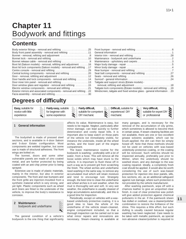
11
Chapter 11Bodywork and fittings
Body exterior fittings - removal and refitting . . . . . . . . . . . . . . . . . . .25Body front panel assembly - removal and refitting . . . . . . . . . . . . . .11Bonnet - removal, refitting and adjustment . . . . . . . . . . . . . . . . . . . . .8Bonnet lock - removal and refitting . . . . . . . . . . . . . . . . . . . . . . . . . .10Bonnet release cable - removal and refitting . . . . . . . . . . . . . . . . . . . .9Boot lid (Saloon models) - removal, refitting and adjustment . . . . . .16Boot lid lock components (Saloon models) - removal and refitting . .17Centre console - removal and refitting . . . . . . . . . . . . . . . . . . . . . . . .29Central locking components - removal and refitting . . . . . . . . . . . . .20Door - removal, refitting and adjustment . . . . . . . . . . . . . . . . . . . . . .12Door handle and lock components - removal and refitting . . . . . . . .14Door inner trim panel - removal and refitting . . . . . . . . . . . . . . . . . . .13Door window glass and regulator - removal and refitting . . . . . . . . .15Electric window components - removal and refitting . . . . . . . . . . . . .21Exterior mirrors and associated components - removal and refitting . .22Facia assembly - removal and refitting . . . . . . . . . . . . . . . . . . . . . . . .30
Front bumper - removal and refitting . . . . . . . . . . . . . . . . . . . . . . . . . .6General information . . . . . . . . . . . . . . . . . . . . . . . . . . . . . . . . . . . . . . .1Interior trim - removal and refitting . . . . . . . . . . . . . . . . . . . . . . . . . . .28Maintenance - bodywork and underframe . . . . . . . . . . . . . . . . . . . . . .2Maintenance - upholstery and carpets . . . . . . . . . . . . . . . . . . . . . . . . .3Major body damage - repair . . . . . . . . . . . . . . . . . . . . . . . . . . . . . . . . .5Minor body damage - repair . . . . . . . . . . . . . . . . . . . . . . . . . . . . . . . . .4Rear bumper - removal and refitting . . . . . . . . . . . . . . . . . . . . . . . . . .7Seat belt components - removal and refitting . . . . . . . . . . . . . . . . . .27Seats - removal and refitting . . . . . . . . . . . . . . . . . . . . . . . . . . . . . . .26Sunroof - general information . . . . . . . . . . . . . . . . . . . . . . . . . . . . . . .24Tailgate and support struts (Estate models) -
removal, refitting and adjustment . . . . . . . . . . . . . . . . . . . . . . . . . .18Tailgate lock components (Estate models) - removal and refitting . .19Windscreen, tailgate and fixed window glass - general information . .23
11•1
Contents
1 General information
The bodyshell is made of pressed steelsections, and is available in 4-door Saloonand 5-door Estate configuration. Mostcomponents are welded together, but someuse is made of structural adhesives. The frontwings are bolted on.
The bonnet, doors and some othervulnerable panels are made of zinc-coatedmetal, and are further protected by beingcoated with an anti-chip primer prior to beingsprayed.
Extensive use is made of plastic materials,mainly in the interior, but also in exteriorcomponents. The front and rear bumpers andthe front grille are injection-moulded from asynthetic material which is very strong, andyet light. Plastic components such as wheelarch liners are fitted to the underside of thevehicle, to improve the body’s resistance tocorrosion.
2 Maintenance -bodywork and underframe 1
The general condition of a vehicle’sbodywork is the one thing that significantly
affects its value. Maintenance is easy, butneeds to be regular. Neglect, particularly afterminor damage, can lead quickly to furtherdeterioration and costly repair bills. It isimportant also to keep watch on those partsof the vehicle not immediately visible, forinstance the underside, inside all the wheelarches, and the lower part of the enginecompartment.
The basic maintenance routine for thebodywork is washing - preferably with a lot ofwater, from a hose. This will remove all theloose solids which may have stuck to thevehicle. It is important to flush these off insuch a way as to prevent grit from scratchingthe finish. The wheel arches and underframeneed washing in the same way, to remove anyaccumulated mud which will retain moistureand tend to encourage rust. Strangelyenough, the best time to clean the underframeand wheel arches is in wet weather, when themud is thoroughly wet and soft. In very wetweather, the underframe is usually cleaned oflarge accumulations automatically, and this isa good time for inspection.
Periodically, except on vehicles with a wax-based underbody protective coating, it is agood idea to have the whole of theunderframe of the vehicle steam-cleaned,engine compartment included, so that athorough inspection can be carried out to seewhat minor repairs and renovations arenecessary. Steam-cleaning is available at
many garages, and is necessary for theremoval of the accumulation of oily grime,which sometimes is allowed to become thickin certain areas. If steam-cleaning facilities arenot available, there are one or two excellentgrease solvents available, which can bebrush-applied; the dirt can then be simplyhosed off. Note that these methods shouldnot be used on vehicles with wax-basedunderbody protective coating, or the coatingwill be removed. Such vehicles should beinspected annually, preferably just prior toWinter, when the underbody should bewashed down, and any damage to the waxcoating repaired. Ideally, a completely freshcoat should be applied. It would also be worthconsidering the use of such wax-basedprotection for injection into door panels, sills,box sections, etc, as an additional safeguardagainst rust damage, where such protection isnot provided by the vehicle manufacturer.
After washing paintwork, wipe off with achamois leather to give an unspotted clearfinish. A coat of clear protective wax polishwill give added protection against chemicalpollutants in the air. If the paintwork sheenhas dulled or oxidised, use a cleaner/polishercombination to restore the brilliance of theshine. This requires a little effort, but suchdulling is usually caused because regularwashing has been neglected. Care needs tobe taken with metallic paintwork, as specialnon-abrasive cleaner/polisher is required to
Easy, suitable fornovice with littleexperience
Fairly easy, suitablefor beginner withsome experience
Fairly difficult,suitable for competentDIY mechanic
Difficult, suitable forexperienced DIYmechanic
Very difficult,suitable for expert DIYor professional
Degrees of difficulty
54321

avoid damage to the finish. Always check thatthe door and ventilator opening drain holesand pipes are completely clear, so that watercan be drained out. Brightwork should betreated in the same way as paintwork.Windscreens and windows can be kept clearof the smeary film which often appears, by theuse of proprietary glass cleaner. Never useany form of wax or other body or chromiumpolish on glass.
3 Maintenance - upholstery and carpets 1
Mats and carpets should be brushed orvacuum-cleaned regularly, to keep them freeof grit. If they are badly stained, remove themfrom the vehicle for scrubbing or sponging,and make quite sure they are dry beforerefitting. Seats and interior trim panels can bekept clean by wiping with a damp cloth. If theydo become stained (which can be moreapparent on light-coloured upholstery), use alittle liquid detergent and a soft nail brush toscour the grime out of the grain of thematerial. Do not forget to keep the headliningclean in the same way as the upholstery.When using liquid cleaners inside the vehicle,do not over-wet the surfaces being cleaned.Excessive damp could get into the seams andpadded interior, causing stains, offensiveodours or even rot. If the inside of the vehiclegets wet accidentally, it is worthwhile takingsome trouble to dry it out properly, particularlywhere carpets are involved. Do not leave oil orelectric heaters inside the vehicle for thispurpose.
4 Minor body damage - repair 2Repairs of minor scratches in bodywork
If the scratch is very superficial, and doesnot penetrate to the metal of the bodywork,repair is very simple. Lightly rub the area ofthe scratch with a paintwork renovator, or avery fine cutting paste, to remove loose paintfrom the scratch, and to clear the surroundingbodywork of wax polish. Rinse the area withclean water.
Apply touch-up paint to the scratch using afine paint brush; continue to apply fine layersof paint until the surface of the paint in thescratch is level with the surroundingpaintwork. Allow the new paint at least twoweeks to harden, then blend it into thesurrounding paintwork by rubbing the scratcharea with a paintwork renovator or a very finecutting paste. Finally, apply wax polish.
Where the scratch has penetrated rightthrough to the metal of the bodywork, causingthe metal to rust, a different repair technique
is required. Remove any loose rust from thebottom of the scratch with a penknife, thenapply rust-inhibiting paint, to prevent theformation of rust in the future. Using a rubberor nylon applicator, fill the scratch withbodystopper paste. If required, this paste canbe mixed with cellulose thinners, to provide avery thin paste which is ideal for filling narrowscratches. Before the stopper-paste in thescratch hardens, wrap a piece of smoothcotton rag around the top of a finger. Dip thefinger in cellulose thinners, and quickly sweepit across the surface of the stopper-paste inthe scratch; this will ensure that the surface ofthe stopper-paste is slightly hollowed. Thescratch can now be painted over as describedearlier in this Section.
Repairs of dents in bodyworkWhen deep denting of the vehicle’s
bodywork has taken place, the first task is topull the dent out, until the affected bodyworkalmost attains its original shape. There is littlepoint in trying to restore the original shapecompletely, as the metal in the damaged areawill have stretched on impact, and cannot bereshaped fully to its original contour. It isbetter to bring the level of the dent up to apoint which is about 3 mm below the level ofthe surrounding bodywork. In cases where thedent is very shallow anyway, it is not worthtrying to pull it out at all. If the underside of thedent is accessible, it can be hammered outgently from behind, using a mallet with awooden or plastic head. Whilst doing this,hold a suitable block of wood firmly againstthe outside of the panel, to absorb the impactfrom the hammer blows and thus prevent alarge area of the bodywork from being“belled-out”.
Should the dent be in a section of thebodywork which has a double skin, or someother factor making it inaccessible frombehind, a different technique is called for. Drillseveral small holes through the metal insidethe area - particularly in the deeper section.Then screw long self-tapping screws into theholes, just sufficiently for them to gain a goodpurchase in the metal. Now the dent can bepulled out by pulling on the protruding headsof the screws with a pair of pliers.
The next stage of the repair is the removalof the paint from the damaged area, and froman inch or so of the surrounding “sound”bodywork. This is accomplished most easilyby using a wire brush or abrasive pad on apower drill, although it can be done just aseffectively by hand, using sheets of abrasivepaper. To complete the preparation for filling,score the surface of the bare metal with ascrewdriver or the tang of a file, oralternatively, drill small holes in the affectedarea. This will provide a really good “key” forthe filler paste.
To complete the repair, see the Section onfilling and respraying.
Repairs of rust holes or gashes in bodywork
Remove all paint from the affected area,and from an inch or so of the surrounding“sound” bodywork, using an abrasive pad or awire brush on a power drill. If these are notavailable, a few sheets of abrasive paper willdo the job most effectively. With the paintremoved, you will be able to judge the severityof the corrosion, and therefore decidewhether to renew the whole panel (if this ispossible) or to repair the affected area. Newbody panels are not as expensive as mostpeople think, and it is often quicker and moresatisfactory to fit a new panel than to attemptto repair large areas of corrosion.
Remove all fittings from the affected area,except those which will act as a guide to theoriginal shape of the damaged bodywork (egheadlamp shells etc). Then, using tin snips ora hacksaw blade, remove all loose metal andany other metal badly affected by corrosion.Hammer the edges of the hole inwards, inorder to create a slight depression for the fillerpaste.
Wire-brush the affected area to remove thepowdery rust from the surface of theremaining metal. Paint the affected area withrust-inhibiting paint; if the back of the rustedarea is accessible, treat this also.
Before filling can take place, it will benecessary to block the hole in some way. Thiscan be achieved by the use of aluminium orplastic mesh, or aluminium tape.
Aluminium or plastic mesh, or glass-fibrematting is probably the best material to usefor a large hole. Cut a piece to theapproximate size and shape of the hole to befilled, then position it in the hole so that itsedges are below the level of the surroundingbodywork. It can be retained in position byseveral blobs of filler paste around itsperiphery.
Aluminium tape should be used for small orvery narrow holes. Pull a piece off the roll, trimit to the approximate size and shape required,then pull off the backing paper (if used) andstick the tape over the hole; it can beoverlapped if the thickness of one piece isinsufficient. Burnish down the edges of thetape with the handle of a screwdriver orsimilar, to ensure that the tape is securelyattached to the metal underneath.
Bodywork repairs - filling and respraying
Before using this Section, see the Sectionson dent, deep scratch, rust holes and gashrepairs.
Many types of bodyfiller are available, butgenerally speaking, those proprietary kitswhich contain a tin of filler paste and a tube ofresin hardener are best for this type of repair.A wide, flexible plastic or nylon applicator willbe found invaluable for imparting a smoothand well-contoured finish to the surface of thefiller.
11•2 Bodywork and fittings

Mix up a little filler on a clean piece of cardor board - measure the hardener carefully(follow the maker’s instructions on the pack),otherwise the filler will set too rapidly or tooslowly. Using the applicator, apply the fillerpaste to the prepared area; draw theapplicator across the surface of the filler toachieve the correct contour and to level thesurface. As soon as a contour thatapproximates to the correct one is achieved,stop working the paste - if you carry on toolong, the paste will become sticky and beginto “pick-up” on the applicator. Continue toadd thin layers of filler paste at 20-minuteintervals, until the level of the filler is justproud of the surrounding bodywork.
Once the filler has hardened, the excesscan be removed using a metal plane or file.From then on, progressively-finer grades ofabrasive paper should be used, starting with a40-grade production paper, and finishing witha 400-grade wet-and-dry paper. Always wrapthe abrasive paper around a flat rubber, cork,or wooden block - otherwise the surface ofthe filler will not be completely flat. During thesmoothing of the filler surface, the wet-and-dry paper should be periodically rinsed inwater. This will ensure that a very smoothfinish is imparted to the filler at the final stage.
At this stage, the “dent” should besurrounded by a ring of bare metal, which inturn should be encircled by the finely“feathered” edge of the good paintwork.Rinse the repair area with clean water, until allof the dust produced by the rubbing-downoperation has gone.
Spray the whole area with a light coat ofprimer - this will show up any imperfections inthe surface of the filler. Repair theseimperfections with fresh filler paste orbodystopper, and once more smooth thesurface with abrasive paper. If bodystopper isused, it can be mixed with cellulose thinners,to form a really thin paste which is ideal forfilling small holes. Repeat this spray-and-repair procedure until you are satisfied thatthe surface of the filler, and the featherededge of the paintwork, are perfect. Clean therepair area with clean water, and allow to dryfully.
The repair area is now ready for finalspraying. Paint spraying must be carried outin a warm, dry, windless and dust-freeatmosphere. This condition can be createdartificially if you have access to a large indoorworking area, but if you are forced to work inthe open, you will have to pick your day verycarefully. If you are working indoors, dousingthe floor in the work area with water will helpto settle the dust which would otherwise be inthe atmosphere. If the repair area is confinedto one body panel, mask off the surroundingpanels; this will help to minimise the effects ofa slight mis-match in paint colours. Bodyworkfittings (eg chrome strips, door handles etc)will also need to be masked off. Use genuinemasking tape, and several thicknesses ofnewspaper, for the masking operations.
Before commencing to spray, agitate theaerosol can thoroughly, then spray a test area(an old tin, or similar) until the technique ismastered. Cover the repair area with a thickcoat of primer; the thickness should be builtup using several thin layers of paint, ratherthan one thick one. Using 400 grade wet-and-dry paper, rub down the surface of the primeruntil it is really smooth. While doing this, thework area should be thoroughly doused withwater, and the wet-and-dry paper periodicallyrinsed in water. Allow to dry before sprayingon more paint.
Spray on the top coat, again building up thethickness by using several thin layers of paint.Start spraying in the centre of the repair area,and then, using a circular motion, workoutwards until the whole repair area andabout 2 inches of the surrounding originalpaintwork is covered. Remove all maskingmaterial 10 to 15 minutes after spraying onthe final coat of paint.
Allow the new paint at least two weeks toharden, then, using a paintwork renovator or avery fine cutting paste, blend the edges of thepaint into the existing paintwork. Finally, applywax polish.
Plastic componentsWith the use of more and more plastic body
components by the vehicle manufacturers (egbumpers. spoilers, and in some cases majorbody panels), rectification of more seriousdamage to such items has become a matterof either entrusting repair work to a specialistin this field, or renewing completecomponents. Repair of such damage by theDIY owner is not really feasible, owing to thecost of the equipment and materials requiredfor effecting such repairs. The basic techniqueinvolves making a groove along the line of thecrack in the plastic, using a rotary burr in apower drill. The damaged part is then weldedback together, using a hot air gun to heat upand fuse a plastic filler rod into the groove.Any excess plastic is then removed, and thearea rubbed down to a smooth finish. It isimportant that a filler rod of the correct plasticis used, as body components can be made ofa variety of different types (eg polycarbonate,ABS, polypropylene).
Damage of a less serious nature (abrasions,minor cracks etc) can be repaired by the DIYowner using a two-part epoxy filler repair.Once mixed in equal parts, this is used insimilar fashion to the bodywork filler used onmetal panels. The filler is usually cured intwenty to thirty minutes, ready for sandingand painting.
If the owner is renewing a completecomponent himself, or if he has repaired itwith epoxy filler, he will be left with theproblem of finding a suitable paint for finishingwhich is compatible with the type of plasticused. At one time, the use of a universal paintwas not possible, owing to the complex rangeof plastics encountered in body componentapplications. Standard paints, generally
speaking, will not bond to plastic or rubbersatisfactorily, but suitable paints to match anyplastic or rubber finish, can be obtained fromdealers. However, it is now possible to obtaina plastic body parts finishing kit whichconsists of a pre-primer treatment, a primerand coloured top coat. Full instructions arenormally supplied with a kit, but basically, themethod of use is to first apply the pre-primerto the component concerned, and allow it todry for up to 30 minutes. Then the primer isapplied, and left to dry for about an hourbefore finally applying the special-colouredtop coat. The result is a correctly-colouredcomponent, where the paint will flex with theplastic or rubber, a property that standardpaint does not normally posses.
5 Major body damage - repair 5Where serious damage has occurred, or
large areas need renewal due to neglect, itmeans that complete new panels will needwelding-in, and this is best left toprofessionals. If the damage is due to impact,it will also be necessary to check completelythe alignment of the bodyshell, and this canonly be carried out accurately by a Peugeotdealer using special jigs. If the body is leftmisaligned, it is primarily dangerous, as thecar will not handle properly, and secondly,uneven stresses will be imposed on thesteering, suspension and possiblytransmission, causing abnormal wear, orcomplete failure, particularly to such items asthe tyres.
6 Front bumper - removal and refitting 2
Removal1 Working at the bottom of the bumper,remove the three lower bumper securingscrews (see illustration).2 Working on one side of the vehicle, removethe three screws securing the outer edge ofthe wheel arch liner, then pull the liner backfrom the bumper.
Bodywork and fittings 11•3
11
6.1 Front bumper lower securing screw

3 Unscrew the two bumper front securingnuts (see illustration).4 Unscrew the bolt securing the side of thebumper to the wing panel (see illustration).5 Repeat the procedure in paragraphs 2 to 4on the remaining side of the vehicle.6 Pull the bumper forwards and, whereapplicable, disconnect the front foglight wiringharness and/or the headlight washer fluidhose. Note the routing of the wiring and/orhose.7 Remove the bumper.
Refitting8 Refitting is a reversal of removal but, whereapplicable, ensure that the foglight wiringand/or washer fluid hose are correctly routed.
7 Rear bumper - removal and refitting 2
Saloon models
Removal1 To improve access, chock the front wheels,then jack up the rear of the vehicle andsupport securely on axle stands (see “Jackingand Vehicle Support”).2 Remove the fixings, and withdraw the rearwheel arch liners (access to the fixings can beimproved by removing the rear roadwheels)(see illustration).3 Unscrew the bumper side securing bolts(one bolt on each side).
4 Working under the bottom of the bumper,unscrew the two lower securing bolts.5 Working in the luggage compartment,locate the number plate light wiringconnector, next to the left-hand rear lightassembly, and separate the two halves of theconnector.6 Pull the carpet trim panel away from therear edge of the luggage compartment toexpose the two remaining bumper securingbolts.7 Pull the bumper rearwards, and feed thenumber plate light wiring harness through thegrommet in the rear body panel.
Refitting8 Refitting is a reversal of removal.
Estate models
Removal9 Proceed as described in paragraphs 1 and 2.
10 On models with rear underbody shieldsfitted under the sides of the bumper, releasethe exhaust system from its rear mounting(loosen the clamp if necessary), then lower therear of the system for access to the left-handrear underbody shield.11 Where applicable, remove the rearunderbody shield(s) to expose the bumperside fixing bolts (see illustration).12 Unscrew the bumper side securing bolts(one bolt on each side) (see illustration).13 Unscrew the two bolts on each side,securing the bumper to the underbodybrackets, then pull the bumper rearwardsfrom the vehicle (see illustration).
Refitting14 Refitting is a reversal of removal.
8 Bonnet - removal, refitting andadjustment 2
Removal1 Open the bonnet and have an assistantsupport it, then, using a pencil or felt tip pen,mark the outline position of each bonnet hingerelative to the bonnet, to use as a guide onrefitting.2 Where applicable, unbolt the earth strapfrom the bonnet.3 Unscrew the bonnet bolts and, with thehelp of the assistant, carefully lift the bonnetfrom the vehicle (see illustration). Store thebonnet out of the way in a safe place.
11•4 Bodywork and fittings
6.3 Front bumper front securing nuts(arrowed)
7.2 Removing a rear wheel arch liner
7.13 Rear bumper side securing bolts(arrowed) - Estate model
7.12 Rear bumper side securing bolt(arrowed) - Estate model
7.11 Rear underbody shield securing clip(arrowed) - Estate model
6.4 Front bumper side securing bolt(arrowed)
8.3 Hinge-to-bonnet bolts (A) and hinge-to-body bolts (B)
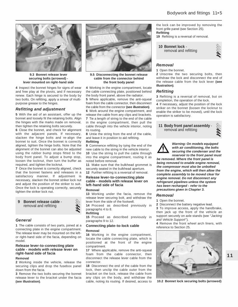
4 Inspect the bonnet hinges for signs of wearand free play at the pivots, and if necessaryrenew. Each hinge is secured to the body bytwo bolts. On refitting, apply a smear of multi-purpose grease to the hinges.
Refitting and adjustment5 With the aid of an assistant, offer up thebonnet and loosely fit the retaining bolts. Alignthe hinges with the marks made on removal,then tighten the retaining bolts securely.6 Close the bonnet, and check for alignmentwith the adjacent panels. If necessary,slacken the hinge bolts and re-align thebonnet to suit. Once the bonnet is correctlyaligned, tighten the hinge bolts. Note that thealignment of the bonnet can also be adjustedusing the rubber bump stops fitted to thebody front panel. To adjust a bump stop,loosen the locknut, then turn the buffer asrequired, and tighten the locknut.7 Once the bonnet is correctly aligned, checkthat the bonnet fastens and releases in asatisfactory manner. If adjustment isnecessary, slacken the bonnet striker lock nutand adjust the position of the striker to suit.Once the lock is operating correctly, securelytighten the striker lock nut.
9 Bonnet release cable -removal and refitting 3
General1 The cable consists of two parts, joined at aconnecting plate in the engine compartment.The release lever may be mounted on the left-or right-hand side of the facia, depending onmodel.
Release lever-to-connecting platecable - models with release lever onright-hand side of faciaRemoval2 Working inside the vehicle, release thesecuring clips and drop the fusebox paneldown from the facia.3 Remove the two bolts securing the bonnetrelease lever to the bracket under the facia(see illustration).
4 Working in the engine compartment, locatethe cable connecting plate, positioned behindthe body front panel, above the radiator.5 Where applicable, remove the anti-squealfoam from the cable connector, then disconnectthe cable from the connector (see illustration).6 Work around the engine compartment, andrelease the cable from any clips and brackets.7 Tie a length of string to the end of the cablein the engine compartment, then pull thecable through into the vehicle interior, notingits routing.8 Untie the string from the end of the cable,and leave it in position to aid refitting.Refitting9 Commence refitting by tying the end of thenew cable to the string in the vehicle interior.10 Use the string to pull the cable throughinto the engine compartment, routing it asnoted before removal.11 Make sure that the bulkhead grommet issecurely seated in the bulkhead aperture.12 Further refitting is a reversal of removal.
Release lever-to-connecting platecable - models with release lever onleft-hand side of faciaRemoval13 Working under the facia, remove therelease lever securing bolt, and withdraw thelever from the side of the footwell.14 Proceed as described previously inparagraphs 4 to 8.Refitting15 Proceed as described previously inparagraphs 9 to 12.
Connecting plate-to-lock cableRemoval16 Working in the engine compartment,locate the cable connecting plate, which ispositioned at the front of the enginecompartment.17 Where applicable, remove the anti-squealfoam from the cable connector, thendisconnect the release lever cable from theconnector.18 Disconnect the end of the cable from thelock, then unclip the cable outer from thebracket on the lock, release the cable fromany clips on the body, and withdraw thecable, noting its routing. If desired, access to
the lock can be improved by removing thefront grille panel (see Section 25).Refitting19 Refitting is a reversal of removal.
10 Bonnet lock - removal and refitting 2
Removal1 Open the bonnet.2 Unscrew the two securing bolts, thenwithdraw the lock and disconnect the end ofthe release cable from the lock lever (seeillustration).
Refitting3 Refitting is a reversal of removal, but oncompletion, the operation of the lock.4 If necessary, adjust the position of the lockstriker on the bonnet (loosen the locknut toenable the striker to be moved), until the lockoperation is satisfactory.
11 Body front panel assembly -removal and refitting 3
Removal1 Open the bonnet.2 Disconnect the battery negative lead.3 To improve access, apply the handbrake,then jack up the front of the vehicle ansupport securely on axle stands (see “Jackingand Vehicle Support”).4 Remove the front wheel arch liners, withreference to Section 25.
Bodywork and fittings 11•5
10.2 Bonnet lock securing bolts (arrowed)
9.5 Disconnecting the bonnet releasecable from the connector behind
the front body panel
9.3 Bonnet release lever securing bolts (arrowed) -
lever mounted on right-hand side
11
Warning: On models equippedwith air conditioning, the boltssecuring the condenser and thereservoir to the front panel must
be removed. Where the front panel isbeing removed to enable engine removal,the compressor must also be unboltedfrom the engine, which will then allow thecomplete assembly to be moved clear forengine removal. Do not disconnect anyrefrigerant pipelines unless the systemhas been recharged - refer to theprecautions given in Chapter 3.

5 Remove the front bumper, as described inSection 6.6 Remove the front direction indicator lights,as described in Chapter 12.7 Disconnect the front light wiringconnectors, located at each front corner ofthe engine compartment on models up to1992, or in the right-hand corner of the enginecompartment on models from 1993 (seeillustrations).8 Unbolt the earth leads from the frontcorners of the engine compartment (seeillustration).9 Where applicable, remove the headlightadjusters from the brackets on the front panel,with reference to Chapter 12.10 Where applicable, disconnect theheadlight washer tubes.11 Locate the bonnet release cableconnecting plate, which is positioned at thetop of the body front panel. Where applicable,
remove the anti-squeal foam from the cableconnector, then disconnect the release levercable from the connector. Unclip the cablefrom the front panel assembly.12 Unscrew the bolts securing the bottom ofthe front panel to the lower crossmember -there may be two or three bolts, depending onmodel (see illustration).13 Remove the radiator as described inChapter 3, but note that provided the radiatoris adequately supported in the enginecompartment, there is no need to disconnectthe coolant hoses (this will avoid the need todrain the cooling system).14 Remove the two upper securing boltsfrom each end of the front panel (seeillustration).15 Carefully release the clips securing thelower headlight trim strips to the front wings.16 Make a final check to ensure that allrelevant wiring has been disconnected toenable removal of the front panel assembly,then withdraw the assembly forwards fromthe front of the vehicle (see illustration).
Refitting17 Refitting is a reversal of removal.
12 Door - removal, refitting andadjustment 3
Removal1 The door hinges are welded to the bodypillar, and bolted to the door.
2 Where applicable, prise the plastic capsfrom the hinge pins.3 Using a pin-punch, drive the roll-pin fromthe door check strap (see illustration).4 On models with electrical componentsinside the door, remove the door trim panelwith reference to Section 13. Working insidethe door, disconnect all the wiring harnessplugs, then feed the wiring through the hole in the front edge of the door. Note the routingof the wiring harness to ensure correctrefitting.5 The door must now be supported in thefully open position.
12.3 Drive the roll-pin (arrowed) from thedoor check strap
11.16 Withdrawing the body front panelassembly
11•6 Bodywork and fittings
11.7a Disconnecting the front light wiringconnectors - models up to 1992
11.7c . . . and disconnect the plug from theterminal block - models from 1993
11.14 Unscrew the body front panel upper securing bolts
11.12 Removing a body front panel lower securing bolt
11.8 Unbolt the earth leads from thecorners of the engine compartment
11.7b Disconnect the front light wiringconnectors (arrowed) . . .
Support the door by placingblocks of wood, or a jackand block of wood, under itslower edge.
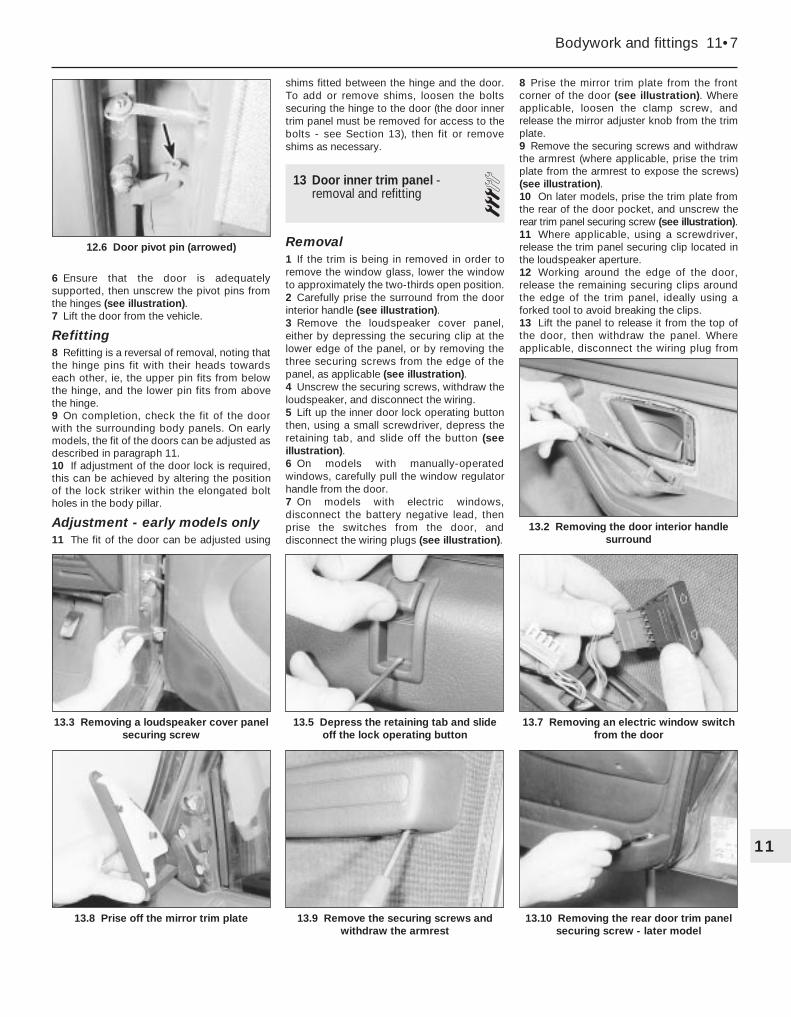
6 Ensure that the door is adequatelysupported, then unscrew the pivot pins fromthe hinges (see illustration).7 Lift the door from the vehicle.
Refitting8 Refitting is a reversal of removal, noting thatthe hinge pins fit with their heads towardseach other, ie, the upper pin fits from belowthe hinge, and the lower pin fits from abovethe hinge.9 On completion, check the fit of the doorwith the surrounding body panels. On earlymodels, the fit of the doors can be adjusted asdescribed in paragraph 11.10 If adjustment of the door lock is required,this can be achieved by altering the positionof the lock striker within the elongated boltholes in the body pillar.
Adjustment - early models only11 The fit of the door can be adjusted using
shims fitted between the hinge and the door.To add or remove shims, loosen the boltssecuring the hinge to the door (the door innertrim panel must be removed for access to thebolts - see Section 13), then fit or removeshims as necessary.
13 Door inner trim panel -removal and refitting 3
Removal1 If the trim is being in removed in order toremove the window glass, lower the windowto approximately the two-thirds open position.2 Carefully prise the surround from the doorinterior handle (see illustration).3 Remove the loudspeaker cover panel,either by depressing the securing clip at thelower edge of the panel, or by removing thethree securing screws from the edge of thepanel, as applicable (see illustration).4 Unscrew the securing screws, withdraw theloudspeaker, and disconnect the wiring.5 Lift up the inner door lock operating buttonthen, using a small screwdriver, depress theretaining tab, and slide off the button (seeillustration).6 On models with manually-operatedwindows, carefully pull the window regulatorhandle from the door.7 On models with electric windows,disconnect the battery negative lead, thenprise the switches from the door, anddisconnect the wiring plugs (see illustration).
8 Prise the mirror trim plate from the frontcorner of the door (see illustration). Whereapplicable, loosen the clamp screw, andrelease the mirror adjuster knob from the trimplate.9 Remove the securing screws and withdrawthe armrest (where applicable, prise the trimplate from the armrest to expose the screws)(see illustration).10 On later models, prise the trim plate fromthe rear of the door pocket, and unscrew therear trim panel securing screw (see illustration).11 Where applicable, using a screwdriver,release the trim panel securing clip located inthe loudspeaker aperture.12 Working around the edge of the door,release the remaining securing clips aroundthe edge of the trim panel, ideally using aforked tool to avoid breaking the clips.13 Lift the panel to release it from the top ofthe door, then withdraw the panel. Whereapplicable, disconnect the wiring plug from
Bodywork and fittings 11•7
13.3 Removing a loudspeaker cover panelsecuring screw
13.8 Prise off the mirror trim plate
13.7 Removing an electric window switchfrom the door
13.5 Depress the retaining tab and slideoff the lock operating button
13.2 Removing the door interior handlesurround
12.6 Door pivot pin (arrowed)
11
13.9 Remove the securing screws andwithdraw the armrest
13.10 Removing the rear door trim panelsecuring screw - later model

the electric windows control unit, which islocated on a bracket attached to the rear ofthe door trim panel.
Refitting14 Refitting is a reversal of removal, bearingin mind the following points.
a) Before refitting, check whether any of thetrim panel retaining clips were broken onremoval, and renew as necessary.
b) Ensure that the weatherstrip (with themetal reinforcing strip) is in place on thetop of the trim panel before refitting, andcheck that the weatherstrip engagescorrectly with the weatherstrip on thedoor as the trim panel is refitted.
c) To refit the inner door lock operatingbutton, first lock the door to ensure thatthe link rod is in its lowest position.Position the button locating tab in thelower of its two holes, then firmly push
the button onto the rod until it clips intoposition and the retaining tab appears inthe upper hole (see illustrations).
14 Door handle and lockcomponents - removal andrefitting
3Interior door handle
Removal1 Remove the door inner trim panel asdescribed in Section 13.2 If necessary, peel the plastic sealing sheetfrom around the handle assembly.3 Slide the handle assembly towards the frontof the door, then pull the assembly from thetrim panel and disconnect the link rod (seeillustration). If necessary, release the link rodfrom the clips on the door.
Refitting4 Refitting is a reversal of removal, ensuringthe link rod is correctly reconnected. Whereapplicable, fit a new sealing sheet if the sheetwas damaged during removal, and refit thedoor trim panel with reference to Section 13.
Exterior door handle
Removal5 Remove the door inner trim panel asdescribed in Section 13.6 Peel back the plastic sealing sheet foraccess to the handle securing nut.7 Unscrew the handle securing nut then,where applicable, manipulate the plastic shieldfrom the rear of the lock (see illustrations).8 Withdraw the handle from outside the door,and disconnect the lock operating rod fromthe handle as it is removed (see illustration).
Refitting9 Refitting is a reversal of removal, ensuringthat the link rod is correctly reconnected. Fit anew sealing sheet if the sheet was damagedduring removal, and refit the door trim panelwith reference to Section 13.
Front door lock cylinder10 The lock cylinder can be removed asfollows, without the need to remove the doorinner trim panel. If no facilities are available tomake up the tools, proceed to paragraph 11.a) Make up two suitable tools, using a
medium-size self-tapping screw brazed toa length of rod for each tool (seeillustration).
14.10a Tool for removing door lock cylinder
All dimensions in mm14.8 Withdrawing the exterior door handle
11•8 Bodywork and fittings
13.14a Position the lock button locatingtab in the lower position
14.3 Unhooking the link rod from theinterior door handle
14.7c . . . and withdraw the plastic shield -later model
14.7b Unscrew the securing nut . . .14.7a Exterior door handle securing nut(arrowed) - early model
13.14b Push the button onto the rod untilretaining tab appears in upper hole (arrowed)
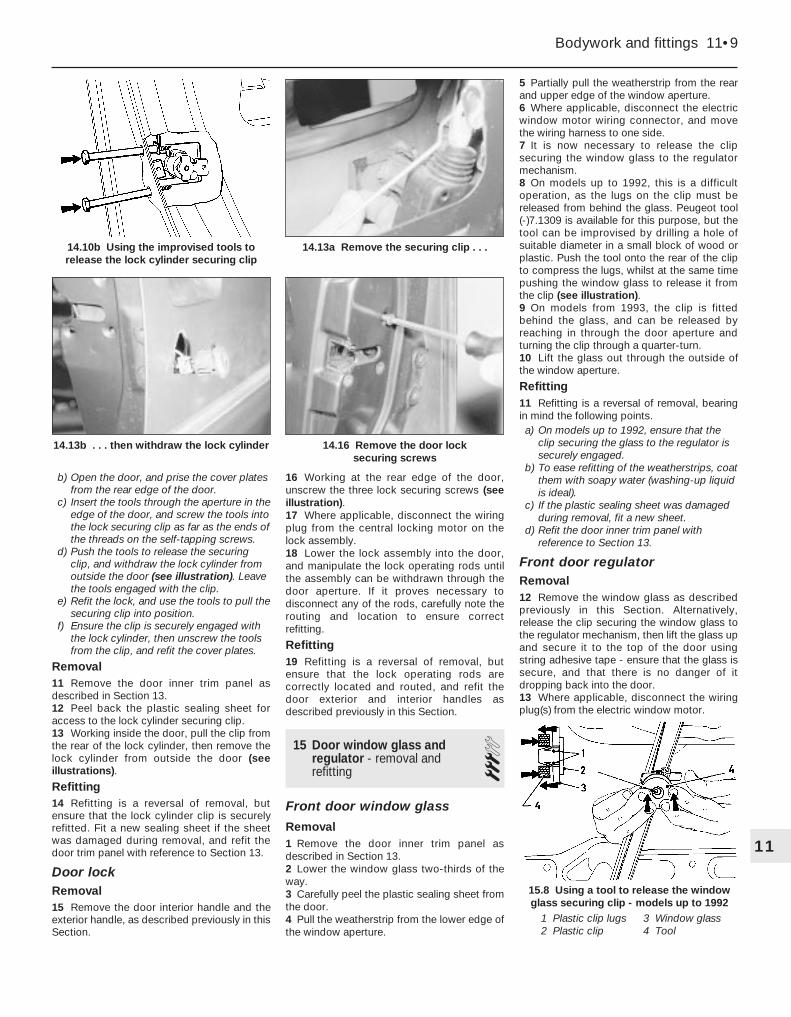
b) Open the door, and prise the cover platesfrom the rear edge of the door.
c) Insert the tools through the aperture in theedge of the door, and screw the tools intothe lock securing clip as far as the ends ofthe threads on the self-tapping screws.
d) Push the tools to release the securingclip, and withdraw the lock cylinder fromoutside the door (see illustration). Leavethe tools engaged with the clip.
e) Refit the lock, and use the tools to pull thesecuring clip into position.
f) Ensure the clip is securely engaged withthe lock cylinder, then unscrew the toolsfrom the clip, and refit the cover plates.
Removal11 Remove the door inner trim panel asdescribed in Section 13.12 Peel back the plastic sealing sheet foraccess to the lock cylinder securing clip.13 Working inside the door, pull the clip fromthe rear of the lock cylinder, then remove thelock cylinder from outside the door (seeillustrations).
Refitting14 Refitting is a reversal of removal, butensure that the lock cylinder clip is securelyrefitted. Fit a new sealing sheet if the sheetwas damaged during removal, and refit thedoor trim panel with reference to Section 13.
Door lockRemoval15 Remove the door interior handle and theexterior handle, as described previously in thisSection.
16 Working at the rear edge of the door,unscrew the three lock securing screws (seeillustration).17 Where applicable, disconnect the wiringplug from the central locking motor on thelock assembly.18 Lower the lock assembly into the door,and manipulate the lock operating rods untilthe assembly can be withdrawn through thedoor aperture. If it proves necessary todisconnect any of the rods, carefully note therouting and location to ensure correctrefitting.
Refitting19 Refitting is a reversal of removal, butensure that the lock operating rods arecorrectly located and routed, and refit thedoor exterior and interior handles asdescribed previously in this Section.
15 Door window glass andregulator - removal andrefitting
3Front door window glass
Removal1 Remove the door inner trim panel asdescribed in Section 13.2 Lower the window glass two-thirds of theway.3 Carefully peel the plastic sealing sheet fromthe door.4 Pull the weatherstrip from the lower edge ofthe window aperture.
5 Partially pull the weatherstrip from the rearand upper edge of the window aperture.6 Where applicable, disconnect the electricwindow motor wiring connector, and movethe wiring harness to one side.7 It is now necessary to release the clipsecuring the window glass to the regulatormechanism.8 On models up to 1992, this is a difficultoperation, as the lugs on the clip must bereleased from behind the glass. Peugeot tool(-)7.1309 is available for this purpose, but thetool can be improvised by drilling a hole ofsuitable diameter in a small block of wood orplastic. Push the tool onto the rear of the clipto compress the lugs, whilst at the same timepushing the window glass to release it fromthe clip (see illustration).9 On models from 1993, the clip is fittedbehind the glass, and can be released byreaching in through the door aperture andturning the clip through a quarter-turn.10 Lift the glass out through the outside ofthe window aperture.
Refitting11 Refitting is a reversal of removal, bearingin mind the following points.a) On models up to 1992, ensure that the
clip securing the glass to the regulator issecurely engaged.
b) To ease refitting of the weatherstrips, coatthem with soapy water (washing-up liquidis ideal).
c) If the plastic sealing sheet was damagedduring removal, fit a new sheet.
d) Refit the door inner trim panel withreference to Section 13.
Front door regulatorRemoval12 Remove the window glass as describedpreviously in this Section. Alternatively,release the clip securing the window glass tothe regulator mechanism, then lift the glass upand secure it to the top of the door usingstring adhesive tape - ensure that the glass issecure, and that there is no danger of itdropping back into the door.13 Where applicable, disconnect the wiringplug(s) from the electric window motor.
Bodywork and fittings 11•9
14.13b . . . then withdraw the lock cylinder
1 Plastic clip lugs2 Plastic clip
3 Window glass4 Tool
15.8 Using a tool to release the windowglass securing clip - models up to 1992
14.16 Remove the door lock securing screws
14.13a Remove the securing clip . . .14.10b Using the improvised tools torelease the lock cylinder securing clip
11
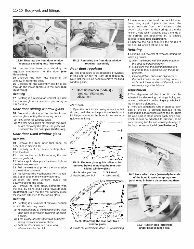
14 Unscrew the three nuts securing theregulator mechanism to the door (seeillustration).15 Unscrew the two nuts securing thewindow lift rail to the door.16 Carefully tilt the assembly and lift it outthrough the lower aperture in the door (seeillustration).
Refitting17 Refitting is a reversal of removal, but refitthe window glass as described previously inthis Section.
Rear door sliding window glass18 Proceed as described for the front doorwindow glass, noting the following points.a) Fully lower the window glass.b) The rear glass guide rail must be removed
before removing the glass. The guide railis secured by two bolts (see illustration).
Rear door fixed window glass
Removal19 Remove the door inner trim panel asdescribed in Section 13.20 Carefully peel the plastic sealing sheetfrom the door.21 Unscrew the two bolts securing the rearwindow guide rail.22 Where applicable, prise the trim strip fromthe fixed window seal.23 Pull the weatherstrip from the lower edgeof the window aperture.24 Partially pull the weatherstrip from the rearand upper edge of the window aperture.25 Slide the rear window guide raildownwards into the door.26 Remove the fixed glass, complete withthe seal, by tilting and pulling forwards (seeillustration). Note that the rear window guiderail remains attached to the sliding glass.
Refitting27 Refitting is a reversal of removal, bearingin mind the following points.a) To ease refitting of the weatherstrips, coat
them with soapy water (washing-up liquidis ideal).
b) If the plastic sealing sheet was damagedduring removal, fit a new sheet.
c) Refit the door inner trim panel withreference to Section 13.
Rear door regulator28 The procedure is as described previouslyin this Section for the front door regulator.Note that there is no need to remove the fixedwindow glass.
16 Boot lid (Saloon models) -removal, refitting andadjustment
2Removal1 Open the boot lid, and using a pencil or felttip pen, mark the outline position of each bootlid hinge relative to the boot lid, to use as aguide on refitting.
2 Have an assistant hold the boot lid openthen, using a pair of pliers, disconnect thespring assisters from the brackets on thebody - take care, as the springs are undertension. Note which bracket slots the ends ofthe springs are positioned in, to ensurecorrect refitting (see illustration).3 Unscrew the bolts securing the hinges tothe boot lid, and lift off the boot lid.
Refitting4 Refitting is a reversal of removal, noting thefollowing points.a) Align the hinges with the marks made on
the boot lid before removal.b) Make sure that the spring assisters are
refitted to their original slots in the bodybrackets.
c) On completion, check the alignment ofthe boot lid with the surrounding panels,and check the operation of the lock, and ifnecessary adjust as follows.
Adjustment5 The alignment of the boot lid can beadjusted by slackening the hinge bolts, andmoving the boot lid on the hinges (the holes inthe hinges are elongated).6 There are adjustable rubber stops at eachside of the lid to prevent damage to thesurrounding panels when closing the lid. Thereare also rubber stops under each hinge arm,which should be adjusted to prevent the lidfrom opening too far and causing damage tothe front corners of the lid (see illustration).
1 Guide rail upper bolt2 Guide rail lower bolt
3 Guide rail4 Weatherstrip
11•10 Bodywork and fittings
15.14 Unscrew the front door windowregulator securing nuts (arrowed)
15.18 The rear glass guide rail must beremoved before removing the rear door
sliding window glass
16.6 Rubber stop (arrowed) under boot lid hinge arm
16.2 Note which slots (arrowed) the endsof the boot lid assister springs are
positioned in before disconnecting them
15.26 Removing the rear door fixedwindow glass
15.16 Removing the front door windowregulator assembly
A Guide rail lowered into door B Weatherstrip

7 Check that the boot lid lock operation issatisfactory, and if necessary adjust bymoving the lock striker (bolted to the boot lid)within its elongated holes.
17 Boot lid lock components(Saloon models) - removaland refitting
3Boot lid lock cylinderNote: New pop-rivets will be required to refitthe body rear trim panel, and on some modelsthe lock cylinder.
Removal1 Open the boot lid.2 Pull the weatherseals from the edge of therear luggage compartment trim panel, thencarefully pull the trim panel from the upperedge of the luggage compartment.3 Drill out the securing rivets from the top ofthe body rear trim panel, then unclip the trimpanel and withdraw it from the rear of thevehicle (see illustration).4 Working in the luggage compartment, whereapplicable unscrew the pinch-bolt, anddisconnect the operating rod from the lockcylinder (see illustration). Similarly, disconnectthe central locking motor rod, where applicable.5 Drill out the rivets, or unscrew the securingbolts, as applicable, and withdraw the lockcylinder from the body panel.
Refitting6 Refitting is a reversal of removal, bearing inmind the following points.a) Refit the body rear trim panel (and the
lock cylinder, where applicable) using newpop-rivets.
b) Check the operation of the lockmechanism before refitting the trim panels.
c) If necessary, on models where theoperating rod is secured to the lockcylinder with a pinch-bolt, adjust the rodas necessary (by slackening the pinch-bolt) until the lock operation issatisfactory.
Boot lid lock
Removal7 Proceed as described in paragraphs 1 and 2.
8 Unscrew the two securing bolts, thenwithdraw the lock and disconnect theoperating rod.
Refitting9 Refitting is a reversal of removal, but checkthe operation of the lock before refitting thetrim panel.
Boot lid lock striker10 The striker is secured to the boot lid bytwo bolts, and can be adjusted by moving itwithin the elongated bolt holes.
18 Tailgate and support struts(Estate models) - removal,refitting and adjustment
3Tailgate
Removal1 Open the tailgate.2 Remove the securing screws, and withdrawthe plastic trim panel from the inside of thetailgate.3 Working around the edge of the carpetedtrim panel, release the securing clips, ideallyusing a forked tool to avoid breaking the clips.Withdraw the carpeted panel.4 Disconnect the heated rear window wiringconnectors from the contacts on the tailgate.5 Disconnect the wiring plug from theluggage compartment light switch, and fromthe alarm sensor switch, where applicable.6 Where applicable, working through theaperture in the tailgate, disconnect the
tailgate wiper motor and the central lockingmotor wiring plugs.7 Disconnect the washer fluid hose from thewasher nozzle.8 Release the wiring harnesses and thewasher fluid hose from any clips inside thetailgate.9 Pull the wiring grommets from the topcorners of the tailgate.10 If the original tailgate is to be refitted, tiestring to the ends of all the relevant wiring,then feed the wiring through the top of thetailgate. Untie the string, leaving it in positionin the tailgate to assist refitting.11 Support the tailgate, then prise out thesupport strut spring clips, and pull the strutsfrom the balljoints on the tailgate.12 Unscrew the nuts securing the hinges tothe top of the tailgate, and carefully lift thetailgate from the vehicle (see illustration).
Refitting13 Refitting is a reversal of removal, bearingin mind the following points.a) If the original tailgate is being refitted,
draw the wiring and washer fluid hose(where applicable) through the tailgate, orthrough the body panel (as applicable)using the string.
b) If necessary, adjust the rubber buffers toobtain a good fit when the tailgate is shut.
c) Before refitting the tailgate trim panels,check and if necessary adjust the positionof the tailgate lock within its elongatedholes to achieve satisfactory lock operation.
Adjustment14 If necessary, the rubber buffers at thesides of the tailgate can be adjusted toachieve firm closure of the tailgate withoutslamming. The tailgate lock operation can beadjusted by altering the position of the lockwithin its elongated holes.
Support struts
Removal15 Support the tailgate in the open position,with the help of an assistant, or using a stoutpiece of wood.16 Using a suitable flat-bladed screwdriver,release the spring clip, and pull the supportstrut from its balljoint on the tailgate (seeillustration).
Bodywork and fittings 11•11
18.12 Hinge-to-tailgate nuts (arrowed)
18.16 Prising the spring clip from atailgate strut balljoint
17.4 Unscrew the lock operating rodpinch-bolt (arrowed)
17.3 Drill out the rivets (arrowed) from thebody rear trim panel
11

17 Similarly, release the strut from theballjoint on the body, and withdraw the strutfrom the vehicle.
Refitting18 Refitting is a reversal of removal, butensure the spring clips are correctly engaged.
19 Tailgate lock components(Estate models) - removaland refitting
3Tailgate lock cylinderNote: New pop-rivets will be required to refitthe lock cylinder.
Removal1 Open the tailgate.2 Remove the securing screws, and withdrawthe plastic trim panel from the inside of thetailgate (see illustration).3 Working around the edge of the carpetedtrim panel, release the securing clips, ideallyusing a forked tool to avoid breaking the clips.Withdraw the carpeted panel (seeillustration).4 Drill out the rivets securing the lock cylinderassembly to the tailgate (see illustration).5 Unhook the operating rod(s), and withdrawthe assembly from the tailgate.6 Remove any rivet swarf from the inside ofthe tailgate.
Refitting7 Refitting is a reversal of removal, but usenew rivets to secure the assembly to thetailgate.
Tailgate lock
Removal8 Proceed as described in paragraphs 1 to 3.9 Unscrew the two bolts securing the lock tothe mounting bracket (see illustration).10 Unhook the lock operating rod, andwithdraw the lock.
Refitting11 Refitting is a reversal of removal, butbefore refitting the tailgate trim panels, checkthe operation of the lock, and if necessaryadjust by moving the lock within its elongatedbolt holes.
Tailgate lid lock striker12 The striker is secured to the body by twobolts.
20 Central locking components - removal and refitting
3Note: Before attempting work on any of thecentral locking system components,disconnect the battery negative lead.Reconnect the lead on completion of work.
Electronic control unit
Removal1 Remove the glovebox as described inSection 28 to reveal the control unit (seeillustration).2 Where applicable, remove the two securingscrews, then unclip the control unit from itslocation, and disconnect the wiring plug (seeillustration).
Refitting3 Refitting is a reversal of removal.
Door lock motor4 The motors are fitted to the door lockassemblies. To remove a motor, remove thelock assembly as described in Section 14,then remove the screws securing the motor tothe lock assembly.
Tailgate lock motor
Removal5 Open the tailgate.6 Remove the securing screws, and withdrawthe plastic trim panel from the inside of thetailgate.7 Working around the edge of the carpetedtrim panel, release the securing clips, ideallyusing a forked tool to avoid breaking the clips.Withdraw the carpeted panel.8 Unscrew the bolt securing the lock motor tothe tailgate (see illustration).9 Manipulate the motor out from the aperturein the tailgate, then disconnect the lockoperating rod and disconnect the wiring plug(see illustration).
Refitting10 Refitting is a reversal of removal.
11•12 Bodywork and fittings
19.2 Withdraw the plastic trim panel from the tailgate . . .
19.4 Tailgate lock cylinder securing rivets(arrowed)
20.2 Removing the central lockingelectronic control unit -
models from 1993
20.1 Central locking electronic control unit(arrowed) viewed with glovebox removed -
models up to 1992
19.9 Tailgate lock securing bolts (arrowed)
19.3 . . . then withdraw the carpeted panel

Boot lid lock motor
Removal11 Open the boot lid.12 Pull the weatherseals from the edge of therear luggage compartment trim panel, thencarefully pull the trim panel from the upperedge of the luggage compartment.13 Remove the securing screws, thenwithdraw the lock motor and disconnect thecontrol rod.14 Disconnect the wiring plug, and withdrawthe motor.
Refitting15 Refitting is a reversal of removal.
Fuel filler flap lock motor -Saloon models
Removal16 On Saloon models, the motor is located in
the luggage compartment, behind the right-hand side trim panels.17 Carefully prise the carpeted trim from theside of the luggage compartment, to exposethe lock motor.18 Open the fuel filler flap, and unscrew thebolt securing the motor to the body.19 Working inside the luggage compartment,unscrew the securing bolt, then withdraw themotor and disconnect the wiring plug.
Refitting20 Refitting is a reversal of removal. Ifnecessary, glue the trim back into position.
Fuel filler flap lock motor -Estate models
Removal21 On Estate models, the motor is located inthe luggage compartment, behind the rearwindow washer reservoir.
22 Working inside the luggage compartment,open the cover flap to expose the rear washerfluid reservoir.23 Remove the two securing screws, then liftout the reservoir to expose the lock motor.Note that there is no need to disconnect thewasher fluid tubing.24 Proceed as described in paragraphs 18and 19 (see illustrations).
Refitting25 Refitting is a reversal of removal.
Remote control receiver unit
Removal26 The unit is located in the roof console.27 Unclip the sunvisors from the roof console.28 Carefully prise the courtesy light assemblyfrom the console to expose the two roofconsole front securing screws. Disconnect thewiring plug and remove the light.29 Similarly, prise the map reading light andthe light surround from the console to exposeone of the front securing screws. Disconnectthe wiring plug and remove the light.30 Prise the blanking plate from the consolethen, where applicable, push the sunroofswitch from the console.31 Remove the two console securing screwsexposed by removal of the map reading lightand sunroof switch, then lower the consolefrom the roof (see illustration).32 Disconnect the wiring plug from thereceiver unit.33 Release the clips, and withdraw thereceiver unit from the console (see illustration).
Refitting34 Refitting is a reversal of removal.
Remote control transmitterbatteries - renewal
Early models35 Using a small screwdriver, carefully prisethe rear cover from the transmitter unit, andremove the three batteries, noting which wayround they are fitted (see illustration).36 Fit the new batteries, ensuring that theyare fitted the correct way round; the batteryand transmitter terminals are marked “+” and“-” to avoid confusion. Clip the transmitterback together.
Bodywork and fittings 11•13
20.24a Remove the bolt securing the fuelfiller flap lock motor to the body
20.33 Central locking remote controlreceiver securing clips (arrowed)
20.31 Removing a roof console securing screw
20.24b Removing the fuel filler flap lockmotor - Estate model
20.9 Disconnecting the wiring plug fromthe tailgate lock motor
20.8 Unscrewing the tailgate lock motorsecuring bolt
11
20.35 Rear cover removed from remotetransmitter to expose batteries (arrowed)

Later models36 Remove the small screws securing thetwo halves of the key/transmitter casingtogether. Remove the two batteries, notingwhich way round they are fitted.37 Fit the new batteries, ensuring that theyare fitted the correct way round. Clip the twohalves of the casing back together and refitthe securing screw.
21 Electric window components - removal and refitting
3Electronic control unit
Removal1 Remove the driver’s door inner trim panelas described in Section 13.
2 The control unit is clipped to a bracket on therear of the door trim panel (see illustration).3 Unclip the control unit and withdraw it fromthe panel.
Refitting4 Refitting is a reversal of removal. Refit thedoor trim panel as described in Section 13.
Window switches5 Refer to Chapter 12.
Window regulator motors6 The regulator motors are integral with theregulator assemblies, and cannot be obtainedseparately.7 Removal and refitting details for theregulator assemblies are given in Section 15.
22 Exterior mirrors andassociated components -removal and refitting
3General1 A number of different types of rear viewmirror may be encountered, according tomodel, and date of manufacture.2 The following paragraphs provide a guideto all types.
Mirror
Removal3 On models with electric mirrors, remove thedoor inner trim panel (Section 13), then peel backthe plastic sealing sheet from the door for access
to the mirror wiring connector(s). Disconnect thewiring connectors (see illustration).4 If not already done, prise the mirror trimplate from the inside front corner of the door.Where applicable, loosen the clamp screw,and release the adjuster knob from the trimplate (see illustration).5 Where applicable, prise the sealing stripand the grommet from the adjuster linkageaperture in the door for access to the lowermirror securing screws (see illustrations).6 Remove the four securing screws, andwithdraw the mirror from the door (seeillustrations). Where applicable, feed thewiring up through the door, noting its routing.
Refitting7 Refitting is a reversal of removal, but whereapplicable refit the door inner trim panel withreference to Section 13.
Mirror glass
Removal8 Various methods have been used to retainthe glass. On some mirrors, the glass cannotbe removed from the housing, and thecomplete mirror unit must be renewed. Themirror glass may be stuck using adhesivepads; on later types of mirror, the glass maybe held by a wire clip, or by a locking ring.9 To remove a mirror glass secured by alocking ring, tilt the glass fully upwards, theninsert a screwdriver at the lower edge of theglass and locate the locking ring. Lever thelocking ring towards the door of the vehicle torelease the glass (see illustration).
22.6b . . . and withdraw the mirror
11•14 Bodywork and fittings
21.2 Disconnecting wiring plug from theelectric windows electronic control unit
22.4 Loosen the clamp screw and releasemirror adjuster knob from the trim plate
22.6a Remove the four securing screws . . .
22.5b . . . and the grommet
22.5a Prise off the sealing strip . . .22.3 Disconnecting the door mirror wiring connectors

10 To remove a mirror glass secured by awire clip, working at the bottom edge of themirror glass, locate the ends of the spring clipwhich secures the glass. Using a screwdriver,push the ends of the clip together to releasethe glass. Withdraw the glass, and disconnectthe wiring, where applicable. Recover thespring clip if it is loose (see illustrations).
Refitting11 On models where the glass is secured bya locking ring, where applicable reconnect thewiring to the glass, then locate the glass in thehousing, and lever the locking ring away fromthe door to lock the glass in position.12 On models where the glass is retained bya wire clip, fit the spring clip to the rear of themirror glass, ensuring that the clip is correctlylocated in the slots in the rear of the mirrorglass. Push the mirror glass into the mirroruntil the spring clip locks into position in themirror adjuster groove. On models where themirror glass is secured by a wire clip, lightlygrease the plastic ring on the adjuster to aidrefitting of the spring clip.
Mirror adjustment mechanism13 The adjustment mechanism is integralwith the mirror assembly, and if faulty, thecomplete mirror must be renewed.
23 Windscreen, tailgate andfixed window glass - general information
These areas of glass are secured by thetight fit of the weatherstrip in the body
aperture, and are bonded in position with aspecial adhesive. Renewal of such fixed glassis a difficult, messy and time-consuming task,which is considered beyond the scope of thehome mechanic. It is difficult, unless one hasplenty of practice, to obtain a secure,waterproof fit. Furthermore, the task carries ahigh risk of breakage; this applies especiallyto the laminated glass windscreen. In view ofthis, owners are strongly advised to have thissort of work carried out by one of the manyspecialist windscreen fitters.
24 Sunroof - general information
General1 The factory-fitted sunroof is of the electrictilt/slide type.
2 Due to the complexity of the sunroofmechanism, considerable skill is required torepair, replace or adjust the sunroof componentssuccessfully. Removal of the roof first requiresthe headlining to be removed, which is a tediousoperation, and not a task to be undertakenlightly. Therefore, any problems with this type ofsunroof should be referred to a Peugeot dealer.3 Removal and refitting of the sunroof motoris described in the following paragraphs.4 Refer to Chapter 12 for details of sunroofswitch removal.
Sunroof motor
Removal5 Disconnect the battery negative lead.6 Prise out the switch(es) and the light(s) fromthe roof console to expose the consolesecuring screws. Disconnect the wiring plugsand withdraw the switch(es) and light(s), ormove them to one side, as applicable. Whereapplicable, also prise out the map readinglight surround.7 Unclip the sun visors from the roof console.8 Remove the screws, and withdraw the roofconsole. Where applicable, release the wiringconnector(s) from the rear of the console.9 Unscrew the earth lead securing bolt.10 Unclip the relay bracket from the roof.11 Unscrew the three screws, and withdrawthe motor assembly from the roof (seeillustration). Where applicable, disconnectthe switch wiring connector.
Refitting12 Refitting is a reversal of removal.
25 Body exterior fittings -removal and refitting 2
Front grille panel
Removal1 Open the bonnet.2 Working through the front of the grille,remove the grille front securing screws (seeillustration).3 Working at the top inner corners of theheadlights, remove the bolts securing theupper corners of the grille (see illustration).
Bodywork and fittings 11•15
22.10b . . . then withdraw the glass anddisconnect the wiring
25.2 Remove the grille front securingscrews . . .
24.11 Sunroof motor securing screws(arrowed)
22.10c Recover the spring clip if it is loose
22.10a Prise ends of the clip apart (seenwith mirror removed and inverted) . . .
22.9 Releasing a mirror glass locking ring
11
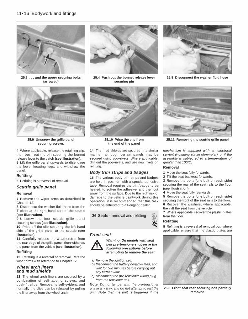
4 Where applicable, release the retaining clip,then push out the pin securing the bonnetrelease lever to the catch (see illustration).5 Lift the grille panel upwards to disengagethe lower locating lugs, and withdraw thepanel.
Refitting6 Refitting is a reversal of removal.
Scuttle grille panel
Removal7 Remove the wiper arms as described inChapter 12.8 Disconnect the washer fluid hose from theT-piece at the right-hand side of the scuttle(see illustration).9 Unscrew the four scuttle grille panelsecuring screws (see illustration).10 Prise off the clip securing the left-handside of the grille panel to the scuttle (seeillustration).11 Carefully release the weatherstrip fromthe rear edge of the grille panel, then withdrawthe panel from the vehicle (see illustration).
Refitting12 Refitting is a reversal of removal. Refit thewiper arms with reference to Chapter 12.
Wheel arch liners and mud shields13 The wheel arch liners are secured by acombination of self-tapping screws, andpush-fit clips. Removal is self-evident, andnormally the clips can be released by pullingthe liner away from the wheel arch.
14 The mud shields are secured in a similarmanner, although certain panels may besecured using pop-rivets. Where applicable,drill out the pop-rivets, and use new rivets onrefitting.
Body trim strips and badges15 The various body trim strips and badgesare held in position with a special adhesivetape. Removal requires the trim/badge to beheated, to soften the adhesive, and then cutaway from the surface. Due to the high risk ofdamage to the vehicle paintwork during thisoperation, it is recommended that this taskshould be entrusted to a Peugeot dealer.
26 Seats - removal and refitting 2Front seat
a) Remove the ignition key.b) Disconnect the battery negative lead, and
wait for two minutes before carrying outany further work.
c) Disconnect the pre-tensioner wiring plugfrom the tensioner unit.
Note: Do not tamper with the pre-tensionerunit in any way, and do not attempt to test theunit. Note that the unit is triggered if the
mechanism is supplied with an electricalcurrent (including via an ohmmeter), or if theassembly is subjected to a temperature ofgreater than 100ºC.
Removal1 Move the seat fully forwards.2 Tilt the seat backrest forwards.3 Remove the bolts (one bolt on each side)securing the rear of the seat rails to the floor(see illustration).4 Move the seat fully rearwards.5 Remove the bolts (one bolt on each side)securing the front of the seat rails to the floor.6 Recover the washers, where applicable,then lift the seat from the vehicle.7 Where applicable, recover the plastic platesfrom the floor.
Refitting8 Refitting is a reversal of removal but, whereapplicable, ensure that the plastic plates are
26.3 Front seat rear securing bolt partiallyremoved
11•16 Bodywork and fittings
25.3 . . . and the upper securing bolts(arrowed)
25.8 Disconnect the washer fluid hose
25.11 Removing the scuttle grille panel25.10 Prise the clip from the end of the panel
25.9 Unscrew the grille panel securing screws
25.4 Push out the bonnet release leversecuring pin
Warning: On models with seatbelt pre-tensioners, observe thefollowing precautions beforeattempting to remove the seat.

in position on the floor, and securely tightenthe mounting bolts.
Rear seat cushion - Saloon models
Removal9 Grasp each lower corner of the seat cushionin turn, and push towards the centre of the car,then pull up to release the securing lug.10 Once both corners have been released,the cushion can be lifted from the vehicle.
Refitting11 Refitting is a reversal of removal, but takecare not to trap the seat belts.
Rear seat back - Saloon models
Removal12 Where applicable, fold down the reararmrest, and remove the screw securing thearmrest trim panel to the body. Withdraw thetrim panel (see illustrations).
13 Pull each side of the seat back upwards todisengage it from the securing lugs, thenwithdraw the assembly from the vehicle.
Refitting14 Refitting is a reversal of removal, but takecare not to trap the seat belts.
Rear seat cushion - Estate models
Removal15 Pull the rear of the seat cushion upwards,using the strap provided, then unscrew thenuts securing the hinges to the floor (seeillustration).
Refitting16 Refitting is a reversal of removal, but takecare not to trap the seat belts.
Rear seat back - Estate modelsRemoval17 Release the seat back retaining catches,and tilt the seat back forwards.18 Unscrew the nuts securing the seat backhinges to the floor, then lift the seat back fromthe vehicle. On models with split rear seatbacks, disengage the inner seat back pivotfrom the central bracket, and remove eachsection individually (see illustrations).
Refitting19 Refitting is a reversal of removal but,where applicable, ensure that the seat beltsare not trapped.
27 Seat belt components -removal and refitting 3
Note: Note the locations of any spacersand/or washers on the seat belt anchor bolts,to ensure correct refitting.
Front seat beltRemoval1 Where applicable, remove the cover, thenunscrew the lower seat belt anchor bolt fromthe edge of the seat.2 Unclip the roof side trim panels to exposethe upper B-pillar trim panel top securingscrews. Remove the screws (see illustration).
3 Prise off the trim plate, and unscrew theseat belt upper anchor bolt (see illustration).Recover the spacer.4 Working at the bottom of the upper B-pillartrim panel, remove the remaining securingscrew, then manipulate the panel from the B-pillar (see illustration).
Bodywork and fittings 11•17
26.15 Rear seat cushion hinge securingnut (arrowed) - Estate model
27.2 Removing an upper B-pillar trimpanel top securing screw
26.18b Split rear seat back inner pivot(arrowed) - Estate model
26.18a Rear seat back hinge securing nuts(arrowed) - Estate model
26.12b . . . and withdraw the armrest trimpanel - Saloon model
26.12a Remove the securing screw . . .
11
27.3 Removing the trim plate from thefront seat belt upper anchor bolt
27.4 Removing the upper B-pillar trimpanel lower securing screw
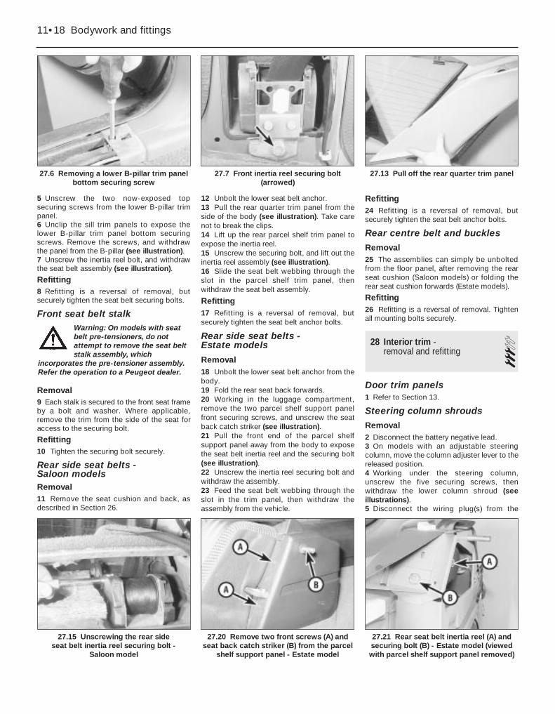
5 Unscrew the two now-exposed topsecuring screws from the lower B-pillar trimpanel.6 Unclip the sill trim panels to expose thelower B-pillar trim panel bottom securingscrews. Remove the screws, and withdrawthe panel from the B-pillar (see illustration).7 Unscrew the inertia reel bolt, and withdrawthe seat belt assembly (see illustration).
Refitting8 Refitting is a reversal of removal, butsecurely tighten the seat belt securing bolts.
Front seat belt stalk
Removal9 Each stalk is secured to the front seat frameby a bolt and washer. Where applicable,remove the trim from the side of the seat foraccess to the securing bolt.
Refitting10 Tighten the securing bolt securely.
Rear side seat belts - Saloon modelsRemoval11 Remove the seat cushion and back, asdescribed in Section 26.
12 Unbolt the lower seat belt anchor.13 Pull the rear quarter trim panel from theside of the body (see illustration). Take carenot to break the clips.14 Lift up the rear parcel shelf trim panel toexpose the inertia reel.15 Unscrew the securing bolt, and lift out theinertia reel assembly (see illustration).16 Slide the seat belt webbing through theslot in the parcel shelf trim panel, thenwithdraw the seat belt assembly.
Refitting17 Refitting is a reversal of removal, butsecurely tighten the seat belt anchor bolts.
Rear side seat belts - Estate models
Removal18 Unbolt the lower seat belt anchor from thebody.19 Fold the rear seat back forwards.20 Working in the luggage compartment,remove the two parcel shelf support panelfront securing screws, and unscrew the seatback catch striker (see illustration).21 Pull the front end of the parcel shelfsupport panel away from the body to exposethe seat belt inertia reel and the securing bolt(see illustration).22 Unscrew the inertia reel securing bolt andwithdraw the assembly.23 Feed the seat belt webbing through theslot in the trim panel, then withdraw theassembly from the vehicle.
Refitting24 Refitting is a reversal of removal, butsecurely tighten the seat belt anchor bolts.
Rear centre belt and buckles
Removal25 The assemblies can simply be unboltedfrom the floor panel, after removing the rearseat cushion (Saloon models) or folding therear seat cushion forwards (Estate models).
Refitting26 Refitting is a reversal of removal. Tightenall mounting bolts securely.
28 Interior trim - removal and refitting 3
Door trim panels1 Refer to Section 13.
Steering column shrouds
Removal2 Disconnect the battery negative lead.3 On models with an adjustable steeringcolumn, move the column adjuster lever to thereleased position.4 Working under the steering column,unscrew the five securing screws, thenwithdraw the lower column shroud (seeillustrations).5 Disconnect the wiring plug(s) from the
11•18 Bodywork and fittings
27.6 Removing a lower B-pillar trim panelbottom securing screw
27.13 Pull off the rear quarter trim panel
27.21 Rear seat belt inertia reel (A) andsecuring bolt (B) - Estate model (viewedwith parcel shelf support panel removed)
27.20 Remove two front screws (A) andseat back catch striker (B) from the parcel
shelf support panel - Estate model
27.15 Unscrewing the rear side seat belt inertia reel securing bolt -
Saloon model
27.7 Front inertia reel securing bolt(arrowed)
Warning: On models with seatbelt pre-tensioners, do notattempt to remove the seat beltstalk assembly, which
incorporates the pre-tensioner assembly.Refer the operation to a Peugeot dealer.

instrument panel illumination control,radio/cassette player remote control switch,cruise control switch, and the alarm electroniccontrol unit, as applicable.6 Unclip the upper shroud from the steeringcolumn.
Refitting7 Refitting is a reversal of removal, but oncompletion, if it proves necessary to adjustthe alignment between the shrouds and thefacia, loosen the steering column securingnuts and bolts. The fixings can be accessedthrough the holes in the lower column shroud(except on models where an electronic controlunit is mounted in the lower shroud, in whichcase the shrouds must be removed again).Adjust the position of the column (and henceshrouds) as necessary, then tighten thecolumn fixings securely.
Glovebox - models up to 1992
Removal8 Working under the glovebox, push out thetwo hinge pins, using a suitable punch or thinscrewdriver if necessary.9 Remove the two screws securing the coverto the rear of the lid.10 Lift off the lid, leaving the cover held bythe checkstraps.11 The checkstraps can be removed byreleasing their inner ends.
Refitting12 Refitting is a reversal of removal, notingthat the longer check strap fits on the left.
Glovebox - models from 1993
Removal13 Working under the glovebox, push out thetwo hinge pins, using a suitable punch or thinscrewdriver if necessary (see illustration).14 Release the glovebox catch, andwithdraw the glovebox from the facia (seeillustration).
Refitting15 Refitting is a reversal of removal.
Carpets16 The passenger compartment floor carpetsare secured at the edges by screws or varioustypes of clips.17 Carpet removal and refitting is reasonablystraightforward, but time-consuming, due tothe fact that all adjoining trim panels must beremoved first, as must components such asthe seats and centre console.
Headlining18 The headlining is clipped to the roof, andcan be withdrawn only once all fittings suchas the grab handles, sun visors, sunroof (iffitted), windscreen, centre and rear pillar trimpanels, and associated panels have beenremoved. The door, tailgate and sunroofaperture weatherstrips will also have to beprised clear.19 Note that headlining removal requiresconsiderable skill and experience if it is to becarried out without damage, and is thereforebest entrusted to an expert.
Bodywork and fittings 11•19
28.13 Remove the hinge pins . . .
29.9 Removing the handbrake lever dustcover - models up to 1992
29.8 “Highline” centre console fixings -models up to 1992
28.14 . . . and withdraw the glovebox -models from 1993
28.4b . . . and withdraw the lower column shroud
28.4a Remove the securing screws . . .
11
29 Centre console - removal and refitting 2
“Highline” console - models up to 1992
Removal1 Disconnect the battery negative lead.2 Move the seats fully rearwards.3 Where applicable, remove the securingscrews, then prise the side panels from thefront of the console. Note that the side panelsare retained by clips at their top edges.4 Prise the cassette box from the front of theconsole, and remove the two now-exposedscrews securing the console to the heaterpanel.5 Slide the front seats fully forward.6 Prise out the blanks from each side at therear of the console, and remove the rearsecuring screws.7 Open the lid of the stowage compartmentat the rear of the console, and remove thescrew from the compartment floor.8 Remove the two screws (one on each side)securing the console to the gear lever bracket(see illustration).9 Pull the handbrake lever dust cover fromthe console (see illustration).10 Prise the gear lever gaiter surround fromthe top of the console, and pull back the gaiter.
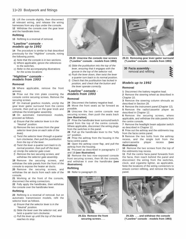
11 Lift the console slightly, then disconnectall relevant wiring, and release the wiringharnesses from any clips under the console.12 Withdraw the console over the gear leverand the handbrake lever.
Refitting13 Refitting is a reversal of removal.
“Lowline” console - models up to 199214 The procedure is similar to that describedpreviously for the “Highline” console, notingthe following points.a) Note that the console is in two sections.b) Where applicable, ignore the references
to the switches.c) Refer to the accompanying illustrations
for the screw locations
“Highline” console - models from 1993
Removal15 Where applicable, remove the frontarmrest.16 Prise out the trim plate covering theconsole centre securing screws. Remove thesecuring screws.17 On manual gearbox models, unclip thegear lever gaiter surround from the centreconsole, then pull up on the gear knob andwithdraw the knob/gaiter assembly.18 On automatic transmission models,proceed as follows.a) Ensure that the selector lever is in the
“Neutral” position.b) Remove the two screws from the gear
selector lever (one on each side of thelever).
c) Twist the selector lever through a quarterturn clockwise, then pull the pushbuttonfrom the top of the lever.
d) Twist the lever a quarter turn back to itsnormal position, then pull off the lever.
e) Unclip the selector gate cover.f) Remove the two securing screws, and
withdraw the selector gate assembly.19 Remove the securing screws, andwithdraw the side panels from the front of theconsole to expose the heater air ducts.20 Remove the securing screws, andwithdraw the air ducts from each side of theconsole.21 Working at the front of the console,disconnect the wiring connectors.22 Fully apply the handbrake, then withdrawthe console over the handbrake lever.
Refitting23 Refitting is a reversal of removal, but onautomatic transmission models, refit theselector lever as follows.a) Ensure that the selector lever is in the
“Neutral” position.b) Slide the lever over the selector rod, and
twist a quarter turn clockwise.c) Pull the lever up until the top of the lever
reaches its stop.
d) Slide the pushbutton into the top of thelever, ensuring that it engages with thegroove in the top of the selector rod.
e) Push the lever down, then twist the levera quarter turn back to its normal position.
f) Check that the pushbutton has locked inposition, and check that the button andthe lever operate correctly.
“Lowline” console - models from 1993
Removal24 Disconnect the battery negative lead.25 Move the front seats as far forward aspossible.26 Unscrew the two centre console rearsecuring screws, then push the seats back(see illustration).27 Prise the handbrake lever surround/switchpanel from the top of the centre console.Where applicable, disconnect the wiring plugsfrom the switches in the panel.28 Pull up the handbrake lever to the “fullyon” position.29 Prise the ashtray from the housing in thefacia centre panel.30 Open the ashtray cover flap, and pull theashtray from the housing.31 Proceed as described in paragraphs 17and 18 (see illustration).32 Remove the two now-exposed consolefront securing screws, then lift the console,and withdraw it over the handbrake (seeillustrations).
Refitting33 Refer to paragraph 23.
30 Facia assembly - removal and refitting 5
Models up to 1992
Removal1 Disconnect the battery negative lead.2 Remove the steering wheel as described inChapter 10.3 Remove the steering column shrouds asdescribed in Section 28.4 Remove the instrument panel (Chapter 12).5 Remove the radio/cassette player asdescribed in Chapter 12.6 Remove the securing screws, whereapplicable, and withdraw the side panels fromthe centre console.7 Remove the headlight beam adjuster switchas described in Chapter 12.8 Prise out the ashtray and the oddments trayfrom the facia centre panel.9 Remove the two bolts from the ashtrayrecess, and the single bolt from theradio/cassette player recess (seeillustrations).10 Remove the two screws from the top ofthe oddments tray recess.11 Pull the centre facia panel forwards fromthe facia, then reach behind the panel anddisconnect the wiring from the switches,clock, and cigarette lighter, as applicable.Note the locations of the wiring connectors toensure correct refitting, and remove the faciapanel.
11•20 Bodywork and fittings
29.26 Unscrew the console rear screws(“Lowline” console - models from 1993)
29.32a Remove the front securing screws . . .
29.32b . . . and withdraw the console(“Lowline” console - models from 1993)
29.31 Removing gear lever gaiter surround(“Lowline” console - models from 1993)

12 Unscrew the four screws securing theheater control panel to the facia (seeillustration).13 Turn the two securing clips through aquarter-turn, then drop the fusebox paneldown from the facia.14 Unscrew the two bonnet release leverbolts from the bracket under the facia.15 Disconnect the wiring from the instrumentpanel lighting rheostat.16 Disconnect the two main feed connectorsfrom the fusebox (see illustration).
17 Working at each side of the facia,disconnect the facia wiring harness connectors,marking them to ensure correct refitting.18 Remove the side footwell trim panel (theleft-hand side panel for right-hand-drivemodels, or the right-hand side panel for left-hand-drive models), then unbolt the earth leadfrom the footwell (see illustration).19 Where applicable, remove the securingbolt, and release the relay bracket from thelower steering column mounting bracket (seeillustration).20 Working in the scuttle at the rear of theengine compartment, unscrew the three faciasecuring nuts (see illustration).21 Remove the single bolt on each side,securing the lower facia mounting brackets tothe footwells (see illustration).22 Remove the remaining two lower faciamounting bolts, one each side of the centreconsole.
23 Reach up behind the heater control panel,and remove the upper facia securing bolt (seeillustration).24 Unbolt the bracing bracket between thegear lever bracket and the centre of the facia.25 Disconnect the remaining steering columnstalk switch wiring connectors.26 Disconnect the wiring from the brake lightswitch.27 Disconnect the wiring from the cigarettelighter and the ashtray illumination light.28 Make a final check around the facia, toensure that all relevant wiring has beendisconnected.29 Carefully pull the facia panel forwards,feeding the speedometer cable and the wiringharnesses through the apertures in the faciaas it is withdrawn. Note the routing of allharnesses and the speedometer cable toensure correct refitting.30 With the aid of an assistant, withdraw the
Bodywork and fittings 11•21
30.12 Two of the heater control panelsecuring screws
30.19 Remove the bolt securing the relaybracket to lower steering column bracket
30.18 Unbolt the earth lead (arrowed) from the footwell
30.16 Disconnect the two main feedconnectors (arrowed) from the fusebox
30.9b . . . and the single bolt (arrowed)from the radio/cassette player recess
30.9a Remove the two bolts (arrowed)from the ashtray recess . . .
11
30.20 Facia securing nut (arrowed) in scuttle
30.21 Lower facia mounting bracket-to-footwell bolt (arrowed)
30.23 Upper facia securing bolt (arrowed)
Because we found thewiring harnesses to bethoroughly intertwined, wedisconnected all the fusebox
connectors, marking them to ensurecorrect refitting. The fusebox can thenbe removed by releasing the hinge rail.

facia assembly through one of the doorapertures.
Refitting31 Refitting is a reversal of removal, bearingin mind the following points.a) Make sure that the facia locating spigots
engage correctly with the holes in thebulkhead.
b) Ensure that the wiring harnesses and thespeedometer cable are correctly routedthrough the facia as it is refitted, as notedduring removal.
c) Ensure that all wiring connectors arecorrectly reconnected.
d) Refit the radio/cassette player and theinstrument panel with reference toChapter 12.
e) Refit the steering wheel (see Chapter 10).
Models from 1993
Removal32 Disconnect the battery negative lead.33 Remove the centre console as describedin Section 29.34 Unscrew the two screws located at thebottom of the ashtray housing (seeillustration).35 Where applicable, remove the radio/cassette player as described in Chapter 12.On models not fitted with a radio/cassetteplayer, prise out the oddments tray.36 Remove the two securing screws from thetop of the radio/cassette player/oddmentstray housing, then withdraw the housing fromthe facia (see illustrations). Whereapplicable, disconnect the wiring plug(s) fromthe rear of the panel.
37 Prise the blanking plate from the topcorner of the facia centre ventilation nozzlehousing. Remove the now-exposed securingscrew (see illustration).38 Remove the four housing securing screwslocated under the heater control panel. Twoscrews are accessible from the front of thehousing, and two screws from underneath(see illustrations).39 Carefully prise the switches from belowthe centre facia ventilation nozzles to revealthe remaining housing securing screw.Remove the screw (see illustrations).40 Pull the housing forwards, and disconnectthe wiring from the clock, then withdraw thehousing (see illustration).41 Working in the driver’s footwell, releasethe securing clips and remove the carpet trimpanel from above the pedals. Disconnect the
11•22 Bodywork and fittings
30.34 Unscrew the two screws below theashtray housing
30.36b . . . then withdraw the housing
30.38b . . . and the two screws fromunderneath
30.38a Remove the two screws from thefront of the ventilation nozzle housing . . .
30.37 Prise out the blanking plate toexpose the ventilation nozzle housing
upper securing screw (arrowed)
30.36a Remove screws from top of radio/cassette player/oddments housing . . .
30.39a Prise the switches from thehousing . . .
30.39b . . . then remove the remaininghousing securing screw
30.40 Withdrawing the ventilation nozzlehousing

three wiring connectors (see illustrations).Where applicable, release the wiringharnesses from the clips on the facia.42 Remove the securing screw, then pull upthe driver’s footwell side trim panel to releasethe securing clips. Remove the panel, to
expose the wiring connector bracket (seeillustrations).43 Release the two securing clips, and pullthe wiring connector bracket from thefootwell. Disconnect the connectors from thebracket (see illustration).
44 Where applicable (if the earth cableconnects to the facia wiring harness), unboltthe earth cable from the footwell, then releasethe wiring harness from the clips under thefacia.45 Working at the centre of the facia, removethe securing screws, and withdraw the faciacentre side trim panels, to expose the heaterair ducts (see illustrations).46 Where applicable remove the screws, andwithdraw the air ducts (see illustration).47 Cut the cable-tie securing the wiringharness to the bracket at the centre of thedriver’s side facia.48 Release the plastic clips securing thelarge connector block to the bracket on thedriver’s side of the centre facia, then releasethe connectors from the connector block, andseparate the two halves of each connector(see illustration).49 Similarly, working at the passenger’s sideof the centre facia, remove the plastic clipssecuring the connector block to the bracketon the floor and to the heater assembly.50 Working in the passenger’s footwell,release the securing clips, and remove thecarpet trim panel from under the facia.51 Remove the securing screw, then pull upthe passenger’s footwell side trim panel torelease the securing clips. Remove the panel,to expose the wiring connector block. Releasethe connector block from the footwell, andseparate the two halves of each wiringconnector.52 Unbolt the earth lead from the passengerfootwell, then release the wiring harnessesfrom any clips in the footwell (see illustration).
Bodywork and fittings 11•23
30.42a Remove the securing screw . . .
30.45a Remove the securing screws . . .
30.43 Pull the connector bracket from the footwell
30.42b . . . then remove the footwell side trim panel
30.41b . . . then disconnect the threewiring connectors (arrowed)
30.41a Remove the carpet trim panel . . .
11
30.45b . . . and withdraw the facia centreside trim panels
30.46 Withdrawing an air duct 30.48 Release the connector block fromthe bracket on the driver’s side of the facia
30.52 Unbolt the earth lead from thepassenger’s footwell

53 Remove the securing screw, andwithdraw the bonnet release lever from theside of the footwell (see illustration).54 Remove the steering column shrouds asdescribed in Section 28, but note that, whereapplicable, there is no need to disconnect thewiring from the radio/cassette player remotecontrol switch - feed the switch wiring upthrough the facia (the wiring should have beendisconnected from the rear of theradio/cassette player), and withdraw thewiring complete with the lower shroud.55 Remove the steering column as describedin Chapter 10.56 Remove the two securing screws, andwithdraw the wiring connector/control unitbracket from the left-hand side of the steeringcolumn bracket (see illustration).57 Where applicable, similarly remove thewiring connector bracket from the right-handside of the steering column bracket.
58 Remove the instrument panel asdescribed in Chapter 12.59 Working in the driver’s footwell,disconnect the wiring plug from the stop lightswitch, then release the switch wiring harnessfrom the clips under the facia.60 Unplug the main wiring harnessconnectors, from the connector blockmounted under the driver’s side of the facia(see illustration). To improve access to thewiring connectors, the connector block canbe lowered from the facia by removing thetwo front bolts securing the bracket to thefacia, and the rear nut securing the bracket tothe stud on the bulkhead.61 On left-hand-drive models, remove thescrew securing the wiring bracket to thedriver’s side of the bulkhead, next to theclutch pedal.62 Where applicable, pull the relay out of itsconnector at the rear of the steering column
bracket, then pull the connector out of thebracket (see illustrations).62 Remove the heater control unit asdescribed in Chapter 3.63 Working in the engine compartment,remove the scuttle grille panel (Section 25).64 Remove the securing clip, and withdrawthe plastic shield from the passenger’s side ofthe scuttle (see illustrations).65 On left-hand-drive models, working in thescuttle, remove the heater inlet duct grille, andmove the connector block/electronic controlunit housing to one side for access to thefacia securing nuts.66 Working inside the vehicle, unscrew thetwo bolts securing the facia side brackets tothe footwells (one bolt in each footwell) (seeillustration).67 Similarly, unscrew the two centre facialower securing bolts, one on each side of thefacia centre section (see illustration).
30.67 Unscrew the centre facia lowersecuring bolts
30.66 Unscrew the bolts securing the facia brackets to the footwells
30.64b . . . and withdraw the shield from the scuttle
11•24 Bodywork and fittings
30.53 Remove the screw and withdraw thebonnet release lever
30.60 Unplug the main wiring harnessconnectors
30.64a Remove the securing clip . . .30.62b . . . then pull the connector fromthe steering column bracket
30.62a Pull the relay out of its connector . . .
30.56 Remove the securing screws andwithdraw connector/control unit brackets
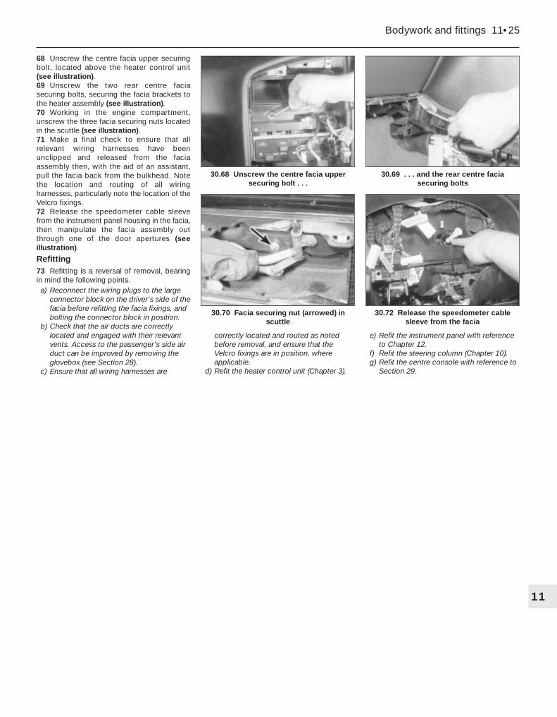
68 Unscrew the centre facia upper securingbolt, located above the heater control unit(see illustration).69 Unscrew the two rear centre faciasecuring bolts, securing the facia brackets tothe heater assembly (see illustration).70 Working in the engine compartment,unscrew the three facia securing nuts locatedin the scuttle (see illustration).71 Make a final check to ensure that allrelevant wiring harnesses have beenunclipped and released from the faciaassembly then, with the aid of an assistant,pull the facia back from the bulkhead. Notethe location and routing of all wiringharnesses, particularly note the location of theVelcro fixings.72 Release the speedometer cable sleevefrom the instrument panel housing in the facia,then manipulate the facia assembly outthrough one of the door apertures (seeillustration).
Refitting73 Refitting is a reversal of removal, bearingin mind the following points.a) Reconnect the wiring plugs to the large
connector block on the driver’s side of thefacia before refitting the facia fixings, andbolting the connector block in position.
b) Check that the air ducts are correctlylocated and engaged with their relevantvents. Access to the passenger’s side airduct can be improved by removing theglovebox (see Section 28).
c) Ensure that all wiring harnesses are
correctly located and routed as notedbefore removal, and ensure that theVelcro fixings are in position, whereapplicable.
d) Refit the heater control unit (Chapter 3).
e) Refit the instrument panel with referenceto Chapter 12.
f) Refit the steering column (Chapter 10).g) Refit the centre console with reference to
Section 29.
Bodywork and fittings 11•25
30.70 Facia securing nut (arrowed) inscuttle
30.69 . . . and the rear centre faciasecuring bolts
30.68 Unscrew the centre facia uppersecuring bolt . . .
11
30.72 Release the speedometer cablesleeve from the facia

12
GeneralSystem type . . . . . . . . . . . . . . . . . . . . . . . . . . . . . . . . . . . . . . . . . . . . . . 12-volt negative earth
Fuses . . . . . . . . . . . . . . . . . . . . . . . . . . . . . . . . . . . . . . . . . . . . . . . . . see Wiring Diagrams
Bulbs Type WattageHeadlights:
Dip/main beam . . . . . . . . . . . . . . . . . . . . . . . . . . . . . . . . . . . . . . . . . . H4 60/55Driving light . . . . . . . . . . . . . . . . . . . . . . . . . . . . . . . . . . . . . . . . . . . . . H1 55
Front foglight/spoiler-mounted driving light . . . . . . . . . . . . . . . . . . . . . . H3 55Front sidelights . . . . . . . . . . . . . . . . . . . . . . . . . . . . . . . . . . . . . . . . . . . . Push-fit 5Direction indicator light . . . . . . . . . . . . . . . . . . . . . . . . . . . . . . . . . . . . . . Bayonet 21Direction indicator side repeater . . . . . . . . . . . . . . . . . . . . . . . . . . . . . . Bayonet 5Stop/tail light . . . . . . . . . . . . . . . . . . . . . . . . . . . . . . . . . . . . . . . . . . . . . . Bayonet 21/5Rear tail light . . . . . . . . . . . . . . . . . . . . . . . . . . . . . . . . . . . . . . . . . . . . . . Bayonet 5Rear foglight . . . . . . . . . . . . . . . . . . . . . . . . . . . . . . . . . . . . . . . . . . . . . . Bayonet 21Reversing light . . . . . . . . . . . . . . . . . . . . . . . . . . . . . . . . . . . . . . . . . . . . Bayonet 21Number plate light . . . . . . . . . . . . . . . . . . . . . . . . . . . . . . . . . . . . . . . . . Push-fit 5
Torque wrench setting Nm lbf ftAir bag unit securing screws . . . . . . . . . . . . . . . . . . . . . . . . . . . . . . . . . 8 6
Chapter 12Body electrical system
Air bag system - general information, precautions and systemde-activation . . . . . . . . . . . . . . . . . . . . . . . . . . . . . . . . . . . . . . . . . .24
Air bag system components - removal and refitting . . . . . . . . . . . . .25Anti-theft alarm system - general information . . . . . . . . . . . . . . . . . .23Bulbs (exterior lights) - renewal . . . . . . . . . . . . . . . . . . . . . . . . . . . . . .5Bulbs (interior lights) - renewal . . . . . . . . . . . . . . . . . . . . . . . . . . . . . . .6Cigarette lighter - removal and refitting . . . . . . . . . . . . . . . . . . . . . . .12Clock - removal and refitting . . . . . . . . . . . . . . . . . . . . . . . . . . . . . . .11Electrical fault finding - general information . . . . . . . . . . . . . . . . . . . . .2Electrical system check . . . . . . . . . . . . . . . . . . . .See “Weekly checks”Exterior light units - removal and refitting . . . . . . . . . . . . . . . . . . . . . . .7Fuses and relays - general information . . . . . . . . . . . . . . . . . . . . . . . .3General information and precautions . . . . . . . . . . . . . . . . . . . . . . . . . .1Headlight beam alignment - general information and
component renewal . . . . . . . . . . . . . . . . . . . . . . . . . . . . . . . . . . . . .8Horn - removal and refitting . . . . . . . . . . . . . . . . . . . . . . . . . . . . . . . .14
Instrument panel - removal and refitting . . . . . . . . . . . . . . . . . . . . . . .9Instrument panel components - removal and refitting . . . . . . . . . . . .10“Lights-on” warning system - general information . . . . . . . . . . . . . . .13Loudspeakers - removal and refitting . . . . . . . . . . . . . . . . . . . . . . . . .21Radio aerial - removal and refitting . . . . . . . . . . . . . . . . . . . . . . . . . .22Radio/cassette player - removal and refitting . . . . . . . . . . . . . . . . . . .20Speedometer cable - removal and refitting . . . . . . . . . . . . . . . . . . . .15Switches - removal and refitting . . . . . . . . . . . . . . . . . . . . . . . . . . . . . .4Tailgate wiper motor - removal and refitting . . . . . . . . . . . . . . . . . . . .18Washer fluid level check . . . . . . . . . . . . . . . . . . . .See “Weekly checks”Windscreen/tailgate/headlight washer system components -
removal and refitting . . . . . . . . . . . . . . . . . . . . . . . . . . . . . . . . . . . .19Windscreen wiper motor and linkage - removal and refitting . . . . . . .17Wiper arm - removal and refitting . . . . . . . . . . . . . . . . . . . . . . . . . . . .16Wiper blade checking and renewal . . . . . . . . . . .See “Weekly checks”
12•1
Specifications
Contents
Easy, suitable fornovice with littleexperience
Fairly easy, suitablefor beginner withsome experience
Fairly difficult,suitable for competentDIY mechanic
Difficult, suitable forexperienced DIYmechanic
Very difficult,suitable for expert DIYor professional
Degrees of difficulty
54321
1 General information andprecautions
The electrical system is of 12-volt negativeearth type. Power for the lights and allelectrical accessories is supplied by alead/acid type battery, which is charged bythe alternator.
This Chapter covers repair and serviceprocedures for the various electricalcomponents not associated with the engine.Information on the battery, alternator andstarter motor can be found in Chapter 5.
It should be noted that, prior to working onany component in the electrical system, thebattery negative terminal should first bedisconnected, to prevent the possibility ofelectrical short-circuits and/or fires.Caution: If the radio/cassette player fittedhas an anti-theft security code, (thestandard unit has), refer to the precautionin the Reference section of this manualbefore disconnecting the battery.
Warning: Before carrying outany work on the electricalsystem, read the precautions in“Safety first!” at the beginningof this manual, and in Chapter 5.

2 Electrical fault finding -general information
Note: Refer to the precautions given in“Safety first!” and in Section 1 of this Chapterbefore starting work. The following tests relateto testing of the main electrical circuits, andshould not be used to test delicate electroniccircuits (such as anti-lock braking systems),particularly where an electronic controlmodule is used.
General1 A typical electrical circuit consists of anelectrical component, any switches, relays,motors, fuses, fusible links or circuit breakersrelated to that component, and the wiring andconnectors which link the component to boththe battery and the chassis. To help topinpoint a problem in an electrical circuit,wiring diagrams are included after thischapter.2 Before attempting to diagnose an electricalfault, first study the appropriate wiringdiagram, to obtain a more completeunderstanding of the components included inthe particular circuit concerned. The possiblesources of a fault can be narrowed down bynoting whether other components related tothe circuit are operating properly. If severalcomponents or circuits fail at one time, theproblem is likely to be related to a shared fuseor earth connection.3 Electrical problems usually stem fromsimple causes, such as loose or corrodedconnections, a faulty earth connection, ablown fuse, a melted fusible link, or a faultyrelay (refer to Section 3 for details of testingrelays). Visually inspect the condition of allfuses, wires and connections in a problemcircuit before testing the components. Usethe wiring diagrams to determine whichterminal connections will need to be checked,in order to pinpoint the trouble-spot.4 The basic tools required for electrical fault-finding include a circuit tester or voltmeter (a12-volt bulb with a set of test leads can alsobe used for certain tests); a self-powered testlight (sometimes known as a continuity tester);an ohmmeter (to measure resistance); abattery and set of test leads; and a jumperwire, preferably with a circuit breaker or fuseincorporated, which can be used to bypasssuspect wires or electrical components.Before attempting to locate a problem withtest instruments, use the wiring diagram todetermine where to make the connections.5 To find the source of an intermittent wiringfault (usually due to a poor or dirtyconnection, or damaged wiring insulation), a“wiggle” test can be performed on the wiring.This involves wiggling the wiring by hand, tosee if the fault occurs as the wiring is moved.It should be possible to narrow down thesource of the fault to a particular section ofwiring. This method of testing can be used in
conjunction with any of the tests described inthe following sub-Sections.6 Apart from problems due to poorconnections, two basic types of fault canoccur in an electrical circuit - open-circuit, orshort-circuit.7 Open-circuit faults are caused by a breaksomewhere in the circuit, which preventscurrent from flowing. An open-circuit fault willprevent a component from working, but willnot cause the relevant circuit fuse to blow.8 Short-circuit faults are caused by a “short”somewhere in the circuit, which allows thecurrent flowing in the circuit to “escape” alongan alternative route, usually to earth. Short-circuit faults are normally caused by abreakdown in wiring insulation, which allows afeed wire to touch either another wire, or anearthed component such as the bodyshell. Ashort-circuit fault will normally cause therelevant circuit fuse to blow.
Finding an open-circuit9 To check for an open-circuit, connect onelead of a circuit tester or voltmeter to eitherthe negative battery terminal or a known goodearth.10 Connect the other lead to a connector inthe circuit being tested, preferably nearest tothe battery or fuse.11 Switch on the circuit, bearing in mind thatsome circuits are live only when the ignitionswitch is moved to a particular position.12 If voltage is present (indicated either bythe tester bulb lighting or a voltmeter reading,as applicable), this means that the section ofthe circuit between the relevant connectorand the battery is problem-free.13 Continue to check the remainder of thecircuit in the same fashion.14 When a point is reached at which novoltage is present, the problem must liebetween that point and the previous test pointwith voltage. Most problems can be traced toa broken, corroded or loose connection.
Finding a short-circuit15 To check for a short-circuit, firstdisconnect the load(s) from the circuit (loadsare the components which draw current froma circuit, such as bulbs, motors, heatingelements, etc).16 Remove the relevant fuse from the circuit,and connect a circuit tester or voltmeter to thefuse connections.17 Switch on the circuit, bearing in mind thatsome circuits are live only when the ignitionswitch is moved to a particular position.18 If voltage is present (indicated either bythe tester bulb lighting or a voltmeter reading,as applicable), this means that there is ashort-circuit.19 If no voltage is present, but the fuse stillblows with the load(s) connected, thisindicates an internal fault in the load(s).
Finding an earth fault20 The battery negative terminal is
connected to “earth” - the metal of theengine/transmission and the car body - andmost systems are wired so that they onlyreceive a positive feed, the current returningvia the metal of the car body. This means thatthe component mounting and the body formpart of that circuit. Loose or corrodedmountings can therefore cause a range ofelectrical faults, ranging from total failure of acircuit, to a puzzling partial fault. In particular,lights may shine dimly (especially whenanother circuit sharing the same earth point isin operation), motors (eg wiper motors or theradiator cooling fan motor) may run slowly,and the operation of one circuit may have anapparently-unrelated effect on another. Notethat on many vehicles, earth straps are usedbetween certain components, such as theengine/transmission and the body, usuallywhere there is no metal-to-metal contactbetween components, due to flexible rubbermountings, etc.21 To check whether a component isproperly earthed, disconnect the battery, andconnect one lead of an ohmmeter to a knowngood earth point. Connect the other lead tothe wire or earth connection being tested. Theresistance reading should be zero; if not,check the connection as follows.22 If an earth connection is thought to befaulty, dismantle the connection, and cleanback to bare metal both the bodyshell and thewire terminal or the component earthconnection mating surface. Be careful toremove all traces of dirt and corrosion, thenuse a knife to trim away any paint, so that aclean metal-to-metal joint is made. Onreassembly, tighten the joint fastenerssecurely; if a wire terminal is being refitted,use serrated washers between the terminaland the bodyshell, to ensure a clean andsecure connection. When the connection isremade, prevent the onset of corrosion in thefuture by applying a coat of petroleum jelly orsilicone-based grease, or by spraying on (atregular intervals) a proprietary ignition sealer.
3 Fuses and relays - general information
Fuses1 Fuses are designed to break a circuit whena predetermined current is reached, in orderto protect the components and wiring whichcould be damaged by excessive current flow.Any excessive current flow will be due to afault in the circuit, usually a short-circuit (seeSection 2).2 The main fuses are located in the fusebox,below the steering column on the driver’s sideof the facia.3 For access to the fuses, on models up to1992, turn the two securing clips through aquarter-turn, then drop the fusebox paneldown from the facia. On models from 1993,
12•2 Body electrical system

prise off the cover to expose the fusebox (seeillustrations).4 Additional fuses may be located in thefusebox on the right-hand side of the enginecompartment, in front of the suspension strut,and/or at the front left-hand corner of theengine compartment (see illustration).5 A blown fuse can be recognised from itsmelted or broken wire.6 To remove a fuse, first ensure that therelevant circuit is switched off.7 Using the plastic tool provided in thefusebox, pull the fuse from its location (seeillustration).8 Spare fuses are provided in the blankterminal positions in the fusebox.9 Before renewing a blown fuse, trace andrectify the cause, and always use a fuse of thecorrect rating. Never substitute a fuse of ahigher rating, or make temporary repairs using
wire or metal foil; more serious damage, oreven fire, could result.10 Note that the fuses are colour-coded asfollows. Refer to the wiring diagrams fordetails of the fuse ratings and the circuitsprotected.
Colour RatingOrange 5ARed 10ABlue 15AYellow 20AClear or white 25AGreen 30A11 If desired, on models from 1993, thefusebox can be withdrawn from the facia asfollows.a) Pull off the fusebox cover.b) Locate the red plastic clip at the left-hand
side of the fusebox, and pull the clip torelease (see illustration).
c) Slide the fusebox to the left, and then pullthe assembly out from the facia (seeillustration).
12 The following fuses are located in theengine compartment fusebox(es).a) Cooling fan.b) ABS.c) Fuel pump (petrol engines).d) Oxygen sensor (petrol engines).e) Engine management electronic control
unit (petrol engines).
Relays13 A relay is an electrically-operated switch,which is used for the following reasons:a) A relay can switch a heavy current
remotely from the circuit in which thecurrent is flowing, allowing the use oflighter-gauge wiring and switch contacts.
b) A relay can receive more than one controlinput, unlike a mechanical switch.
c) A relay can have a timer function - forexample, the intermittent wiper relay.
14 Most of the relays are located under thefacia, behind the main fusebox, and mountedon various brackets around the steeringcolumn. The rear wiper motor relay is locatedin the tailgate, behind the tailgate trim panel.On some models, additional engine-relatedrelays are located in the relay box mounted atthe front left-hand corner of the enginecompartment, or in the left-hand corner of thescuttle (see illustrations).15 If a circuit or system controlled by a relaydevelops a fault, and the relay is suspect,operate the system. If the relay is functioning,
Body electrical system 12•3
3.3c Removing the fusebox cover - later models
3.11a Pull out the securing clip . . .
3.7 Removing a fuse using the plastic tool3.4 Fusebox location on right-hand side ofengine compartment
3.3b . . . and lower the fusebox panel -early models
3.3a Release the securing clips (arrowed) . . .
12
3.11b . . . to release the fusebox - models from 1993
3.14a Removing a relay from the mainfusebox - models up to 1992

it should be possible to hear it “click” as it isenergised. If this is the case, the fault lies withthe components or wiring of the system. If therelay is not being energised, then either therelay is not receiving a main supply or aswitching voltage, or the relay itself is faulty.Testing is by the substitution of a known goodunit, but be careful - while some relays areidentical in appearance and in operation,others look similar but perform differentfunctions.16 To remove a relay, first ensure that therelevant circuit is switched off. The relay canthen simply be pulled out from the socket,and pushed back into position.
4 Switches - removal and refitting 3
Ignition switch/steering column lock1 Refer to Chapter 10.
Steering column combination switches
Models up to 19922 Remove the steering column shrouds, asdescribed in Chapter 11.3 Working under the switch, unscrew the twoscrews securing the switch to the steeringcolumn bracket (see illustration).4 Withdraw the switch, and disconnect the
wiring connector(s). Note the routing of thewiring to aid refitting.5 Refitting is a reversal of removal, ensuringthe wiring is routed as noted before removal.
Models from 19936 Proceed as described previously formodels up to 1992, but note that the securingscrews are accessed from the front of theswitch (see illustrations).
Radio/cassette player remote control and cruisecontrol stalk switches7 Remove the lower steering column shroudsas described in Chapter 11.8 Remove the securing screws, and withdrawthe switch from the column shroud.9 Disconnect the wiring plug(s) and removethe switch.
10 Refitting is a reversal of removal; to refitthe steering column shroud, see Chapter 11.
Facia-mounted pushbutton switchesModels up to 199211 Use a small flat-bladed screwdriver at thesides of the switch to release the plasticretaining tabs, then carefully prise the switchfrom the facia (see illustration).12 Disconnect the wiring plug and withdrawthe switch.13 To refit, reconnect the wiring plug, thenpush the switch into position in the facia.
Models from 199314 Proceed as described previously formodels up to 1992, but note that the securingclips are released by prising at the top andbottom of the switch (see illustration).
12•4 Body electrical system
3.14b Unscrewing a relay bracketsecuring screw from under the steeringcolumn - models from 1993 (viewed with
steering column shrouds removed)
3.14d Relays in engine compartment relay box - models up to 1992
4.6b . . . and withdraw the steering columncombination switch - models from 1993
4.6a Remove the securing screws . . .4.3 Steering column combination switchscrews (arrowed) - models up to 1992
3.14c Main relay box located behindfusebox at rear of facia - models from 1993(viewed with facia removed and inverted)
4.11 Removing a driver’s side facia-mounted switch - models up to 1992
4.14 Prising out a facia-mounted switch -models from 1993

Headlight beam adjustment switch
Models up to 199215 The switch is integral with the adjustmentmechanism. Refer to Section 8 for details ofhow to remove the mechanism.
Models from 199316 Carefully prise the switch from the faciapanel using a small screwdriver (take care notto damage the trim), then disconnect thewiring plug and withdraw the switch.17 Refitting is a reversal of removal.
Heater blower motor switch18 The switch is integral with the heatercontrol panel, and cannot be renewedseparately. Removal and refitting details forthe heater control panel are given in Chapter 3.
Centre console-mounted switches
Front switches19 Prise out the trim panel from the bottomof the oddments tray below the handbrakelever (see illustration).20 Prise off the switch trim panel (seeillustration).21 Prise the switch from the centre console,and disconnect the wiring plug (seeillustration).22 Refitting is a reversal of removal.
Rear switches23 Prise the rear ashtray from the centreconsole.
24 Prise off the switch trim panel (seeillustration).25 Prise the switch from the centre console,and disconnect the wiring plug (see illustration).26 Refitting is a reversal of removal.
Door-mounted switches27 Prise the switch from its location in thedoor, and disconnect the wiring plug.28 Refitting is a reversal of removal.
Courtesy light switches
Door-pillar-mounted switches29 Open the door, then prise the rubbergaiter from the switch (see illustration).30 Remove the securing screw, thencarefully withdraw the switch from the doorpillar. Disconnect the wiring connector as itbecomes accessible, bearing in mind thedanger of losing the wiring connector (seeHaynes Hint).
31 Refitting is a reversal of removal, butensure that the rubber gaiter is correctlyseated on the switch.
Roof panel-mounted switches32 The switches are integral with the lights,and cannot be renewed separately.
Luggage compartment light switch
Saloon models33 Open the boot lid.34 The switch is located in a bracket at therear of the boot, and is operated by the bootlid hinge.35 Release the clips, and pull the switch fromthe bracket (see illustration).36 Disconnect the wiring plug and withdrawthe switch.37 Refitting is a reversal of removal.
Estate models38 The light is operated by a tilt-sensitiveswitch fitted inside the tailgate.39 Open the tailgate.40 Remove the screws, and withdraw theplastic trim panel from inside the tailgate.41 Working around the edge of the carpetedtrim panel, release the securing clips, ideallyusing a forked tool to avoid breaking the clips.Withdraw the carpeted panel.
Body electrical system 12•5
4.21 . . . and remove the switch
4.29 Rubber gaiter pulled back to exposecourtesy light securing screw (arrowed)
4.25 . . . for access to the switches4.24 Prising off a rear centre consoleswitch trim panel . . .
4.20 . . . then prise off the switch trim panel . . .
4.19 Prise the trim panel from the bottomof the oddments tray . . .
12
4.35 Removing the luggage compartmentcourtesy light switch - Saloon model
Tape the wiring to the doorpillar, to prevent it fallingback into the door pillar.Alternatively, tie a piece of
string to the wiring, to retrieve it.

42 Remove the screw securing the switch tothe tailgate. Where applicable, recover thelockwasher (see illustration).43 Disconnect the wiring plug and withdrawthe switch.44 Refitting is a reversal of removal.
Map reading light switch45 The switch is integral with the light, andcannot be renewed separately.
Electric sunroof switch46 Carefully prise the blanking plate (fittednext to the sunroof switch) from the centreconsole (see illustration).47 Reach in through the aperture left byremoval of the blanking plate, then push outthe switch and disconnect the wiring plug(see illustration).48 Refitting is a reversal of removal.
5 Bulbs (exterior lights) -renewal 2
1 Whenever a bulb is renewed, note thefollowing points.a) Disconnect the battery negative lead
before starting work.b) Remember that, if the light has just been
in use, the bulb may be extremely hot.c) Always check the bulb contacts and
holder, ensuring that there is clean metal-to metal contact between the bulb and itslive(s) and earth. Clean off any corrosionor dirt before fitting a new bulb.
d) Wherever bayonet-type bulbs are fitted(see Specifications), ensure that the livecontact(s) bear firmly against the bulbcontact.
e) Always ensure the new bulb is of thecorrect rating, and that it is completelyclean before fitting it; this appliesparticularly to headlight/foglight bulbs(see below).
Headlight2 Working in the engine compartment,release the clip securing the cover to the rearof the headlight unit. Withdraw the cover (seeillustration).
3 Disconnect the wiring plug from the rear ofthe headlight bulb.4 Release the spring clip securing the bulb inthe light unit, then withdraw the bulb (seeillustrations).5 When handling the new bulb, use a tissueor clean cloth, to avoid touching the glasswith the fingers; moisture and grease from theskin can cause blackening and rapid failure ofthis type of bulb. If the glass is accidentallytouched, wipe it clean using methylated spirit.6 Install the new bulb, ensuring that it locatescorrectly in the light unit. Secure the bulb inposition with the spring clip, and reconnectthe wiring plug.7 Refit the cover to the rear of the light unit,and secure with the clip.
Front sidelight8 The sidelight bulb is located in the rear ofthe headlight housing.
9 Working in the engine compartment,release the clip securing the cover to the rearof the headlight unit.10 On models up to 1992, pull the bulbholderfrom the rear of the headlight unit. On modelsfrom 1993, it will be necessary to twist thebulbholder through a quarter turn before it canbe removed (see illustration).11 The bulb is a push-fit in the bulbholder(see illustration).12 Refitting is the reverse of the removalprocedure, ensuring that the bulbholder sealis in good condition.
Front direction indicator13 Working in the engine compartment,unhook the indicator light unit retaining springfrom the lug behind the light (see illustration).14 Pull the light forwards from the wing panel.15 Twist the bulbholder anti-clockwise torelease it from the light unit (see illustration).
12•6 Body electrical system
4.42 Luggage compartment courtesy lightswitch screw (arrowed) - Estate model
4.47 . . . then prise out the sunroof switch
5.4b . . . then withdraw the headlight bulb
5.4a Release the spring clip (arrowed) . . .
5.2 Headlight rear cover securing clip(arrowed)
4.46 Prise out the blanking plate . . .
5.10 Pull out the sidelight bulbholder . . .

16 The bulb is a bayonet-fit in the bulbholder.17 Refitting is a reversal of removal, butensure that the light unit retaining spring iscorrectly engaged.
Front direction indicator side repeater18 Twist the light unit a quarter-turn anti-clockwise, and carefully pull the unit from thewing panel, taking care not to damage thepaint.19 Twist the bulbholder anti-clockwise, andremove it from the light unit.20 The bulb is a bayonet-fit in the bulbholder(see illustration).21 Refitting is a reversal of the removalprocedure.
Headlight-mounted front driving light22 On certain models, a driving light ismounted in the headlight unit. The lightoperates when the headlights are switched tomain beam.23 Proceed as described previously in thisSection for the headlight bulb (see illustrations).
Front spoiler-mounted driving light/foglightNote: Some models are fitted with frontfoglights which have no securing screwsvisible from the front of the lens. At the time ofwriting, no information was available for thistype of foglight.24 Two alternative types of light assemblymay be fitted, depending on model. On somemodels, access to the bulb can be obtained
from the behind the spoiler. On other models,the light unit must be removed for access tothe bulb.25 On models where the light unit can bereached from behind the spoiler, reach up
behind the spoiler and disconnect the wiringfrom the light. Prise the rubber cover from thelight, then release the spring clip andwithdraw the bulb.26 On models where the rear of the light unitis covered by the spoiler, remove the twosecuring screws from the front of the light unitand withdraw the reflector/lens assembly.Disconnect the wiring from the bulb, thenrelease the spring clip and withdraw the bulb.27 When handling the new bulb, use a tissueor clean cloth, to avoid touching the glasswith the fingers; moisture and grease from theskin can cause blackening and rapid failure ofthis type of bulb. If the glass is accidentallytouched, wipe it clean using methylated spirit.28 Refitting is the reverse of the removalprocedure, ensuring that the bulb locatescorrectly in its housing.
Rear light cluster
Saloon models29 Open the boot lid.30 Squeeze the two retaining clips, andwithdraw the bulbholder from the rear of thelight unit (see illustration).31 The bulbs are a bayonet-fit in thebulbholder (see illustration).32 Fit the new bulb using a reversal of theremoval procedure.
Estate models33 The stop/tail lights and the directionindicator lights are located in the rear wingpanels. The remaining rear lights are locatedin the tailgate.
Body electrical system 12•7
5.15 Withdrawing the bulbholder from thefront direction indicator light
5.23b Removing a headlight-mounteddriving light bulb
5.23a Headlight-mounted driving light bulbsecuring clip (arrowed)
5.20 Removing the bulbholder from thefront direction indicator side repeater light
5.13 Front direction indicator lightretaining spring (arrowed)
5.11 . . . and withdraw the bulb
12
5.30 Removing a rear light clusterbulbholder - Saloon model
5.31 The bulbs are a bayonet-fit in thebulbholder

34 Open the tailgate.35 Turn the retaining clip and open the lightunit cover flap.36 Squeeze the two retaining clips, andwithdraw the bulbholder from the rear of thelight unit (see illustrations).37 The bulbs are a bayonet-fit in thebulbholder.38 Fit the new bulb using a reversal of theremoval procedure.
Number plate light
Saloon models39 Prise the lens from the underside of thebumper for access to the bulb (seeillustration).40 The bulb is a bayonet-fit in the bulbholder(see illustration).41 Fit the new bulb using a reversal of theremoval procedure.
Estate models42 Carefully prise the light unit from thetailgate (see illustration).43 Unclip the bulbholder from the lensassembly (see illustration).44 The bulb is a bayonet-fit in the bulbholder.45 Fit the new bulb using a reversal of theremoval procedure.
6 Bulbs (interior lights) -renewal 2
General1 Refer to Section 5, paragraph 1.
Courtesy light, glovebox andluggage compartment lights2 Carefully prise the lens from the light unit.
Note that in some cases, it may provenecessary to prise out the complete light unitto enable the lens to be removed (seeillustrations).3 The bulb is a push-fit in the holder.4 Refitting is a reversal of removal.
Map reading light5 Prise the map reading light from the roofconsole.6 The festoon-type bulb is held between thespring contacts (see illustration).7 Refitting is a reversal of removal.
Heater/ventilation control unit illumination bulbs
Models up to 19928 For access to the bulbs, the control unitmust be removed as described in Chapter 11,but note that there is no need to disconnectthe control cables from the unit. Once the
12•8 Body electrical system
5.36a Removing a rear wing-mounted lightbulbholder - Estate model
5.39 Prise the lens from the bumper . . .
5.43 . . . and unclip the bulbholder fromthe lens - Estate model
5.42 Prise out the number plate light unit . . .
5.40 . . . and withdraw the number platelight bulb - Saloon model
5.36b Removing a tailgate-mounted lightbulbholder - Estate model
6.2a Prising out a courtesy light 6.2b Prise off the lens for access to the bulb
6.6 Map reading light removed for access to bulb

securing screws have been removed, thecontrol unit can be pulled forwards sufficientlyfor access to the bulbs without disconnectingthe cables.
Models from 19939 Disconnect the battery negative lead.10 Remove the centre console as describedin Chapter 11, Section 29.11 Unscrew the two screws located at thebottom of the ashtray housing.12 Where applicable, remove the radio/cassette player as described in Section 20.On models not fitted with a radio/cassetteplayer, prise out the oddments tray.13 Remove the two securing screws from thetop of the radio/cassette player/oddmentstray housing, then withdraw the housing fromthe facia. Where applicable, disconnect thewiring plug(s) from the rear of the panel.14 Prise the blanking plate from the topcorner of the facia centre ventilation nozzlehousing. Remove the now-exposed securingscrew.15 Remove the four housing securing screwslocated under the heater control panel. Twoscrews are accessible from the front of thehousing, and two screws from underneath.16 Carefully prise the switches from belowthe centre facia ventilation nozzles to revealthe remaining housing securing screw.Remove the screw.17 Pull the housing forwards, and disconnectthe wiring from the clock, then withdraw thehousing.18 Carefully pull the knobs from the heatercontrol levers.
19 Unclip the front panel from the heatercontrol unit to expose the bulbs (seeillustration).20 The bulbs are a push-fit in the bulbholders(see Haynes Hint).21 Refitting is a reversal of removal.
Clock illumination bulb22 For access to the clock illumination bulb,remove the clock as described in Section 11.Note that on models from 1993, access to thebulb can be gained once the housing hasbeen removed from the facia - there is noneed to remove the clock from the housing.23 To remove the bulbholder, twist it anti-clockwise (see illustration). The bulb isintegral with the bulbholder.24 Fit the new bulb using a reversal of theremoval procedure.
Facia switch illumination bulbs25 The bulbs are integral with the switches,and cannot be renewed independently.
Instrument panel illuminationand warning light bulbs26 Remove the instrument panel asdescribed in Section 9.27 Twist the relevant bulbholder anti-clockwise to remove it from the rear of thepanel (see illustration).28 The bulbs are a push-fit in thebulbholders.29 On completion, refit the instrument panelwith reference to Section 9.
7 Exterior light units - removal and refitting 2
Note: Disconnect the battery negative leadbefore removing any light unit, and reconnectthe lead after refitting the unit.
Headlight
Removal1 Working in the engine compartment,release the clip securing the cover to the rearof the headlight unit.2 Disconnect the wiring plugs from the bulbslocated in the headlight unit.3 Remove the direction indicator light asdescribed during the bulb renewal procedurein Section 5.4 On models with cable-operated headlightadjusters, disconnect the adjuster from theheadlight as follows.a) Tun the adjuster and pull it from the
bracket on the body front panel.b) Carefully pull the balljoint from the socket
in the rear of the headlight (seeillustration).
5 On models with electrically-operatedheadlight adjusters, disconnect the wiringplug from the adjuster in the rear of theheadlight.6 Remove the radiator grille panel asdescribed in Chapter 11.7 Carefully prise the lower trim plate from thebottom of the headlight (see illustration).
Body electrical system 12•9
6.23 Removing the clock illumination bulb- models from 1993
7.7 Removing the trim plate from thebottom of the headlight
7.4 Removing a cable-operated headlight adjuster
6.27 Removing an instrument panelillumination bulb
6.19 Unclip the front panel from the heater control unit
12
A length of rubber tubing can be usedto remove and refit the bulbs

8 Unscrew the two outer headlight securingbolts, and pull the unit forwards from the bodypanel (see illustration).9 If desired, the headlight lens can berenewed by prising off the metal securingclips and withdrawing the lens from the frontof the light unit (see illustration).10 Before fitting a new lens, ensure that theseal located in the groove around the front ofthe headlight is in good condition, and renewif necessary.
Refitting11 Refitting is a reversal of removal, but oncompletion have the headlight beamalignment checked at the earliest opportunity.
Front direction indicator12 The procedure is described as part of thebulb renewal procedure in Section 5.
Front direction indicator side repeater13 The procedure is described as part of thebulb renewal procedure in Section 5.
Front spoiler-mounted driving light/foglight14 Two alternative types of light assemblymay be fitted, depending on model. The lightmay be mounted either directly in the frontspoiler, or in a cowl screwed to the frontspoiler.
Cowl-mounted light15 Reach up behind the spoiler, anddisconnect the wiring from the light.
16 Remove the two screws securing the lightcowl to the spoiler, then withdraw thecowl/light assembly rearwards from thebumper (see illustration).17 The light unit can be removed from thecowl after unscrewing the knurled securingnut at the rear of the unit (see illustration).18 Refitting is a reversal of removal, but oncompletion, check and if necessary adjust thelight beam alignment. Adjustment can bemade using the knurled nuts at the rear of theunit.
Light mounted directly in spoilerNote: Some models are fitted with frontfoglights which have no securing screwsvisible from the front of the lens. At the time ofwriting, no information was available for thistype of foglight.19 To improve access, jack up the front ofthe vehicle and support securely on axlestands (see “Jacking and Vehicle Support”).20 Trace the wiring back from the rear of thefoglight, and disconnect the wiring connector.21 Slacken and remove the foglight securingnut, and withdraw the light unit from thespoiler. Recover any washers and spacers,noting their locations to ensure correctrefitting.22 Refitting is a reversal of removal, ensuringthat any washers and spacers on the securingstud are positioned as noted before removal.
Rear light cluster
Saloon models23 Open the boot lid.
24 Squeeze the two retaining clips, andwithdraw the bulbholder from the rear of thelight unit.25 Disconnect the wiring plug from thebulbholder.26 Pull up the luggage compartment weather-strip, and release the luggage compartmentinner trim panel from the rear panel to exposethe light unit securing nuts.27 Unscrew the securing nuts, then withdrawthe unit from outside the vehicle. Withdrawthe outboard side of the unit first, thendisengage the inboard edge from the body(see illustrations).28 Refitting is a reversal of removal
Estate models29 The stop/tail lights and the directionindicator lights are located in the rear wingpanels. The remaining rear lights are locatedin the tailgate.30 Open the tailgate.31 Turn the retaining clip and open the lightunit cover flap.32 Squeeze the two retaining clips, andwithdraw the bulbholder from the rear of thelight unit.33 Disconnect the wiring plug from thebulbholder.34 Unscrew the securing nuts and withdrawthe light unit from outside the vehicle (seeillustrations).35 Refitting is a reversal of removal.
Number plate lightSaloon models36 Remove the two securing screws, then
12•10 Body electrical system
7.8 Outer headlight securing bolts(arrowed)
7.16 Remove the front driving light/foglight cowl securing screws
7.27b . . . then withdraw the rear light unit- Saloon model
7.27a Unscrew the securing nuts(arrowed) . . .
7.17 Unscrew the nut (arrowed) toseparate the light from the cowl
7.9 Removing a headlight lens securing clip
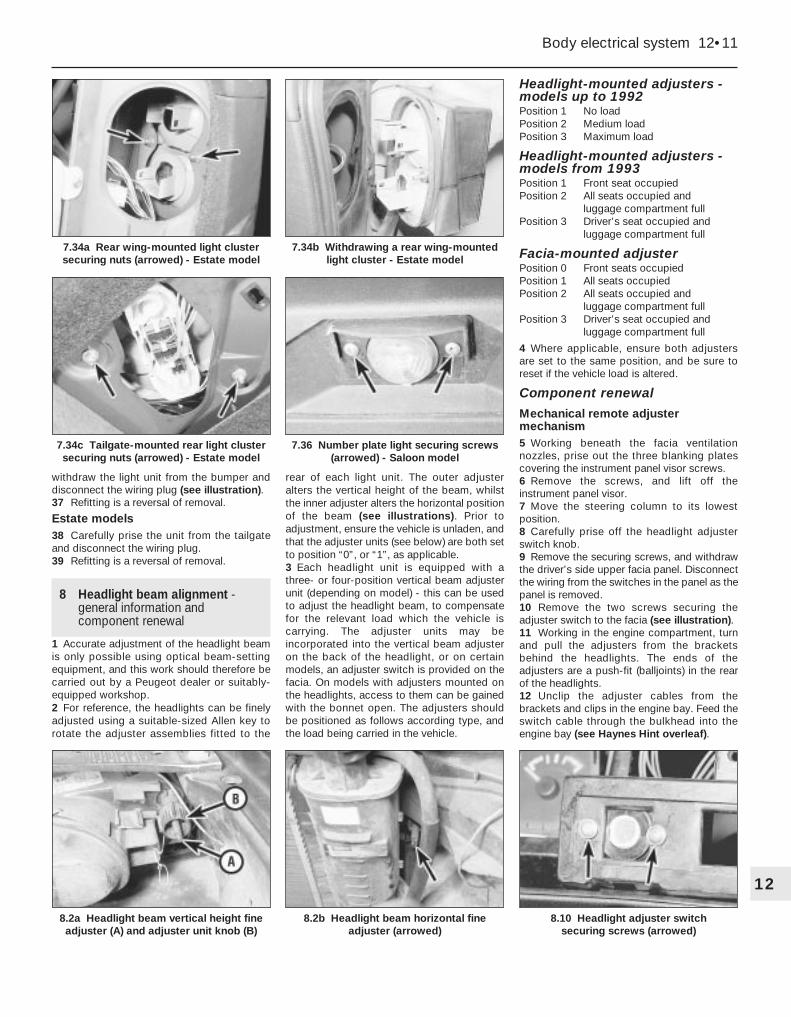
withdraw the light unit from the bumper anddisconnect the wiring plug (see illustration).37 Refitting is a reversal of removal.
Estate models38 Carefully prise the unit from the tailgateand disconnect the wiring plug.39 Refitting is a reversal of removal.
8 Headlight beam alignment -general information andcomponent renewal
1 Accurate adjustment of the headlight beamis only possible using optical beam-settingequipment, and this work should therefore becarried out by a Peugeot dealer or suitably-equipped workshop.2 For reference, the headlights can be finelyadjusted using a suitable-sized Allen key torotate the adjuster assemblies fitted to the
rear of each light unit. The outer adjusteralters the vertical height of the beam, whilstthe inner adjuster alters the horizontal positionof the beam (see illustrations). Prior toadjustment, ensure the vehicle is unladen, andthat the adjuster units (see below) are both setto position “0”, or “1”, as applicable.3 Each headlight unit is equipped with athree- or four-position vertical beam adjusterunit (depending on model) - this can be usedto adjust the headlight beam, to compensatefor the relevant load which the vehicle iscarrying. The adjuster units may beincorporated into the vertical beam adjusteron the back of the headlight, or on certainmodels, an adjuster switch is provided on thefacia. On models with adjusters mounted onthe headlights, access to them can be gainedwith the bonnet open. The adjusters shouldbe positioned as follows according type, andthe load being carried in the vehicle.
Headlight-mounted adjusters -models up to 1992Position 1 No loadPosition 2 Medium loadPosition 3 Maximum load
Headlight-mounted adjusters -models from 1993Position 1 Front seat occupiedPosition 2 All seats occupied and
luggage compartment fullPosition 3 Driver’s seat occupied and
luggage compartment full
Facia-mounted adjuster Position 0 Front seats occupiedPosition 1 All seats occupiedPosition 2 All seats occupied and
luggage compartment fullPosition 3 Driver’s seat occupied and
luggage compartment full
4 Where applicable, ensure both adjustersare set to the same position, and be sure toreset if the vehicle load is altered.
Component renewal
Mechanical remote adjustermechanism5 Working beneath the facia ventilationnozzles, prise out the three blanking platescovering the instrument panel visor screws.6 Remove the screws, and lift off theinstrument panel visor.7 Move the steering column to its lowestposition.8 Carefully prise off the headlight adjusterswitch knob.9 Remove the securing screws, and withdrawthe driver’s side upper facia panel. Disconnectthe wiring from the switches in the panel as thepanel is removed.10 Remove the two screws securing theadjuster switch to the facia (see illustration).11 Working in the engine compartment, turnand pull the adjusters from the bracketsbehind the headlights. The ends of theadjusters are a push-fit (balljoints) in the rearof the headlights.12 Unclip the adjuster cables from thebrackets and clips in the engine bay. Feed theswitch cable through the bulkhead into theengine bay (see Haynes Hint overleaf).
Body electrical system 12•11
7.34c Tailgate-mounted rear light clustersecuring nuts (arrowed) - Estate model
8.2b Headlight beam horizontal fineadjuster (arrowed)
8.2a Headlight beam vertical height fineadjuster (A) and adjuster unit knob (B)
7.36 Number plate light securing screws(arrowed) - Saloon model
7.34b Withdrawing a rear wing-mountedlight cluster - Estate model
7.34a Rear wing-mounted light clustersecuring nuts (arrowed) - Estate model
12
8.10 Headlight adjuster switch securing screws (arrowed)

13 Refitting is a reversal of removal. Whereapplicable, use the string to pull the cable intoposition through the bulkhead into thepassenger compartment.
Electric adjuster switch14 Refer to Section 4.
Electric adjuster unit15 Disconnect the battery negative lead.16 Working at the rear of the headlight,disconnect the wiring plug from the adjusterunit (mounted in the rear of the headlight).17 Twist the adjuster unit (or the lockingcollar, as applicable) to release the adjusterfrom the aperture in the headlight unit.
9 Instrument panel - removal and refitting 2
Models up to 1992
Removal1 Disconnect the battery negative lead.2 Working beneath the facia ventilationnozzles, prise out the three blanking platescovering the instrument panel visor securingscrews (see illustration).3 Remove the screws, and lift off theinstrument panel visor (see illustrations).4 Move the steering column to its lowestposition.5 Where applicable, carefully prise off theheadlight adjuster switch knob (see illustration).6 Remove the securing screws, and withdrawthe driver’s side upper facia panel (seeillustration). Disconnect the wiring from theswitches in the panel as the panel is removed.7 Unclip the trim panel from the lower edge ofthe instrument panel to expose the uppercentre facia panel securing screw. Removethe screw (see illustration).8 Remove the instrument panel screws fromthe top corners of the panel (see illustration).
9 Tilt the instrument panel forwards, anddisconnect the speedometer cable from therear of the panel. Give the cable end fitting asharp tug to free it from the speedometer.10 Disconnect the wiring plugs from the rearof the instrument panel, noting their locationsto ensure correct refitting.11 Lift the instrument panel from the facia.
Refitting12 Refitting is a reversal of removal, butensure that the wiring plugs are correctlyreconnected, and make sure that the cable issecurely reconnected to the speedometer,before securing the instrument panel inposition in the facia.
Models from 1993
Removal13 Disconnect the battery negative lead.14 Release the securing clips, and remove
the lower trim panel from the driver’s footwell.15 Where applicable, move the steeringcolumn adjuster lever to the released position.16 Working under the steering columnloosen, but do not remove, the lower steeringcolumn securing bolts (note that on somemodels, it will be necessary to remove thesteering column shrouds for access to thesteering column securing bolts - see Chapter11).17 Similarly, unscrew and remove the twoupper steering column securing nuts.18 Cover the upper steering column shroudwith cloth to protect it during the followingprocedure.19 Working under the instrument panel, prisethe ends of the trim panel upwards to releaseit from the facia, and withdraw the panel (seeillustration). If necessary, unscrew the lowersteering column fixings further to enable thecolumn to be lowered sufficiently for access.
9.8 Instrument panel securing screw(arrowed)
12•12 Body electrical system
9.2 Prise out the blanking plates . . .
9.3b Instrument panel visor securingscrew locations (arrowed)
9.7 Remove the upper centre facia panelsecuring screw
9.6 Withdrawing the driver’s side upper facia panel
9.5 Prise off the headlight adjuster switch knob
9.3a . . . and remove the visor securing screws
Tie a length of string to theend of the adjuster cablebefore pulling it through thebulkhead. Untie the string
and leave it in position to aid refitting.
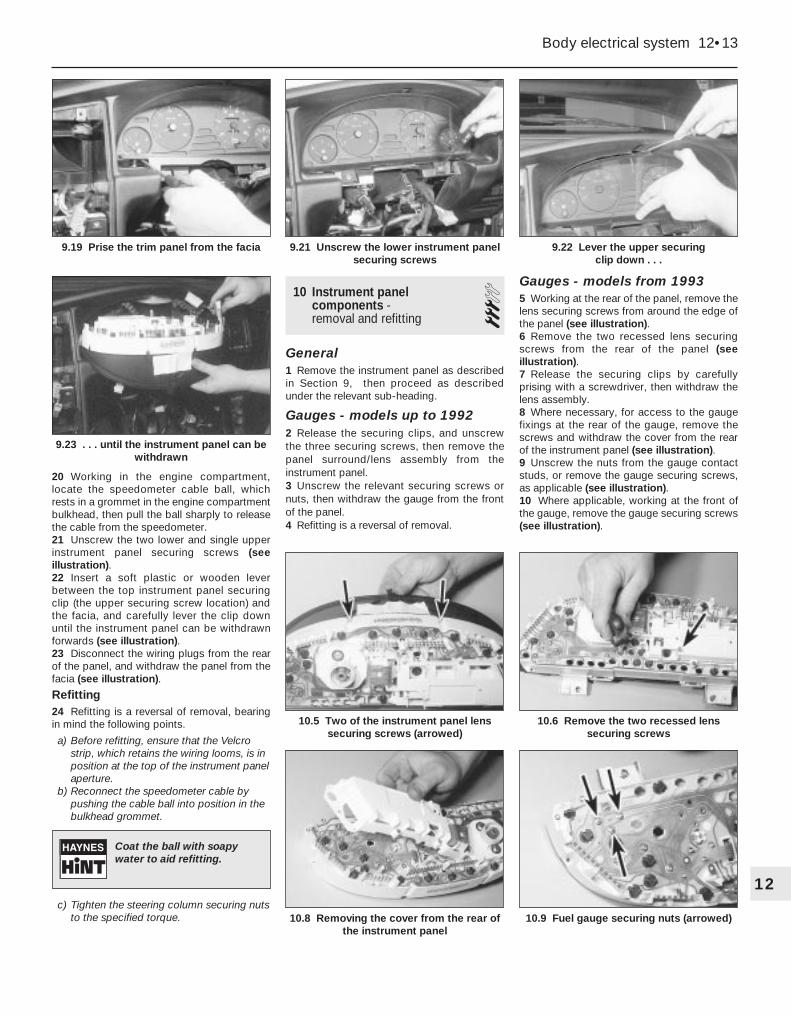
20 Working in the engine compartment,locate the speedometer cable ball, whichrests in a grommet in the engine compartmentbulkhead, then pull the ball sharply to releasethe cable from the speedometer.21 Unscrew the two lower and single upperinstrument panel securing screws (seeillustration).22 Insert a soft plastic or wooden leverbetween the top instrument panel securingclip (the upper securing screw location) andthe facia, and carefully lever the clip downuntil the instrument panel can be withdrawnforwards (see illustration).23 Disconnect the wiring plugs from the rearof the panel, and withdraw the panel from thefacia (see illustration).
Refitting24 Refitting is a reversal of removal, bearingin mind the following points.
a) Before refitting, ensure that the Velcrostrip, which retains the wiring looms, is inposition at the top of the instrument panelaperture.
b) Reconnect the speedometer cable bypushing the cable ball into position in thebulkhead grommet.
c) Tighten the steering column securing nutsto the specified torque.
10 Instrument panelcomponents - removal and refitting
3General1 Remove the instrument panel as describedin Section 9, then proceed as describedunder the relevant sub-heading.
Gauges - models up to 19922 Release the securing clips, and unscrewthe three securing screws, then remove thepanel surround/lens assembly from theinstrument panel.3 Unscrew the relevant securing screws ornuts, then withdraw the gauge from the frontof the panel.4 Refitting is a reversal of removal.
Gauges - models from 19935 Working at the rear of the panel, remove thelens securing screws from around the edge ofthe panel (see illustration).6 Remove the two recessed lens securingscrews from the rear of the panel (seeillustration).7 Release the securing clips by carefullyprising with a screwdriver, then withdraw thelens assembly.8 Where necessary, for access to the gaugefixings at the rear of the gauge, remove thescrews and withdraw the cover from the rearof the instrument panel (see illustration).9 Unscrew the nuts from the gauge contactstuds, or remove the gauge securing screws,as applicable (see illustration).10 Where applicable, working at the front ofthe gauge, remove the gauge securing screws(see illustration).
Body electrical system 12•13
9.22 Lever the upper securing clip down . . .
10.6 Remove the two recessed lenssecuring screws
10.5 Two of the instrument panel lenssecuring screws (arrowed)
9.23 . . . until the instrument panel can bewithdrawn
9.21 Unscrew the lower instrument panelsecuring screws
9.19 Prise the trim panel from the facia
12
Coat the ball with soapywater to aid refitting.
10.8 Removing the cover from the rear ofthe instrument panel
10.9 Fuel gauge securing nuts (arrowed)

11 Carefully withdraw the gauge from thefront of the instrument panel, taking care not todamage the circuit board. Where applicable,recover the spacers from the gauge studs (seeillustrations).12 Refitting is a reversal of removal. Makesure that the spacers are in position on thegauge studs, where applicable.
Illumination and warning light bulbs13 Twist the relevant bulbholder anti-clockwise to release it from the rear of thepanel. The bulbs are integral with thebulbholders.
11 Clock - removal and refitting 3Models up to 1992
Removal1 Disconnect the battery negative lead.2 Working beneath the facia ventilationnozzles, prise out the three blanking platescovering the instrument panel visor securingscrews.3 Remove the screws, and lift off theinstrument panel visor (see illustration 9.3b).4 Working at the rear of the clock, release thesecuring clips, then pull the clock from therear of the facia panel.5 Disconnect the wiring plug and withdrawthe clock (see illustration).
Refitting6 Refitting is a reversal of removal.
Models from 1993
Removal7 Disconnect the battery negative lead.8 Remove the centre console as described inChapter 11, Section 29.9 Open the ashtray cover, and unscrew thetwo screws located at the bottom of theashtray housing.10 Where applicable, remove the radio/cassette player as described in Section 20.On models not fitted with a radio/cassetteplayer, prise out the oddments tray.11 Remove the two securing screws from thetop of the radio/cassette player/oddmentstray housing, then withdraw the housing fromthe facia. Where applicable, disconnect thewiring plug(s) from the rear of the housing.12 Prise the blanking plate from the topcorner of the facia centre ventilation nozzlehousing. Remove the now-exposed securingscrew.13 Remove the four housing securing screwslocated under the heater control panel. Twoscrews are accessible from the front of thehousing, and a two screws from underneath.14 Carefully prise the switches from belowthe centre facia ventilation nozzles to revealthe remaining housing securing screw.Remove the screw (see illustration).15 Pull the housing forwards, and disconnectthe wiring from the clock, then withdraw thehousing (see illustration).16 Working at the rear of the clock, remove
the two securing screws, then withdraw theclock from the housing.
Refitting17 Refitting is a reversal of removal. Refit theradio/cassette player, referring to Section 20.
12 Cigarette lighter - removal and refitting 2
Front cigarette lighter - models up to 1992
Removal1 Disconnect the battery negative lead.2 Prise the lower stowage tray from thecentre console.3 Prise the side panels from the front of theconsole.4 Working behind the ashtray housing,disconnect the wiring from the cigarettelighter and the illumination bulb.5 Again working behind the housing, depressthe cigarette lighter securing clips, and pushthe unit forwards from the housing.
Refitting6 Refitting is a reversal of removal.
Front cigarette lighter - models from 19937 Disconnect the battery negative lead.8 Remove the centre console as described inChapter 11, Section 29.9 Open the ashtray cover, and unscrew the
12•14 Body electrical system
10.10 Remove the gauge securing screws . . .
10.11b . . . and recover the spacers fromthe studs
11.15 . . . then withdraw the housing11.14 Remove the centre facia ventilationnozzle housing lower securing screw . . .
11.5 Removing the clock - models up to 1992
10.11a . . . then withdraw the gauge . . .

two screws located at the bottom of theashtray housing.10 Where applicable, remove the radio/cassette player as described in Section 20.On models not fitted with a radio/cassetteplayer, prise out the oddments tray.11 Remove the two securing screws from thetop of the radio/cassette player/oddmentstray housing, then withdraw the housing fromthe facia. Disconnect the wiring plug(s) fromthe rear of the housing.12 Working behind the housing, depress thecigarette lighter securing clips, and push theunit forwards from the housing.
Rear cigarette lighter13 The procedure is similar to that describedpreviously for the front lighter, except thataccess is obtained by removing the rearashtray from the centre console.
13 “Lights-on” warning system - general information
1 The purpose of this system is to inform thedriver that the lights have been left on oncethe ignition has been switched off; the buzzerwill sound when a door is opened. The systemconsists of a buzzer unit which is linked to thedriver’s door courtesy light switch.2 On models up to 1992, the buzzer unit islocated behind the fuses in the facia fusebox,and access can be obtained once the fuseboxcover has been removed. The unit is a push-fitin the panel, and can be identified by the slotsin its cover (see illustration).3 On models from 1993, the buzzer unit islocated in the relay block, behind the fusebox(see illustration).4 Refer to Section 4 for information oncourtesy light switch removal.
14 Horn - removal and refitting 2Removal1 There may be a single horn or double hornsmounted behind the front bumper (on some
models, one horn is mounted on each side ofthe vehicle).2 Disconnect the battery negative lead.3 Where applicable, remove the wheel archliner(s) to improve access.4 Reach up behind the bumper, anddisconnect the wiring from the horn.5 Unscrew the nut securing the horn to themounting bracket, and withdraw the horn (seeillustration).
Refitting6 Refitting is a reversal of removal.
15 Speedometer cable - removal and refitting 4
Removal1 Working in the engine compartment, locatethe speedometer cable ball, which rests in agrommet in the engine compartmentbulkhead, then pull the ball sharply to releasethe cable from the speedometer.2 Remove the instrument panel (Section 9).3 Tie a length of string to the end of thespeedometer cable at the speedometer end.4 Working at the gearbox/transmission end ofthe cable, remove the pin securing the cableend fitting to the gearbox/transmissionhousing.5 Pull the cable through the bulkheadgrommet into the engine compartment, thenwithdraw the cable from the vehicle. Ifdesired, access to the bulkhead grommet can
be obtained from the driver’s footwell afterunclipping the carpet trim panel from thelower facia.6 Untie the string from the end of the cable,and leave the string in position to aid refitting.
Refitting7 Refitting is a reversal of removal, but usethe string to pull the cable into position, andmake sure that the cable ball is correctlylocated in the bulkhead grommet. Coat theball with soapy water to aid refitting. If itproves difficult to engage the speedometercable with the rear of the speedometer,proceed as follows.a) Cut the two clips securing the ball/sleeve
assembly to the speedometer cable, andslide the ball/sleeve down the cable.
b) Push the cable until it engages with thespeedometer, then slide the ball sleeveinto position, and engage it with thebulkhead grommet.
c) Fit a hose clip or cable-tie to the lowerend of the ball/sleeve to secure it inposition on the cable.
d) If it still proves difficult to engage the cablewith the speedometer, remove theinstrument panel, then carry out the aboveprocedure, engaging the end of the cablewith the speedometer directly by hand,before refitting the instrument panel.
16 Wiper arm - removal and refitting 1
Removal1 Operate the wiper motor, then switch it offso that the wiper arm returns to the at-restposition.
2 Where applicable, disconnect the washerfluid hose from the end of the connector onthe scuttle grille panel (see illustration).3 Lift up the wiper arm spindle nut cover, then
Body electrical system 12•15
14.5 Horn securing nut (arrowed) - viewedfrom underneath vehicle
16.2 Disconnect the washer fluid hosefrom the connector
13.3 “Lights on” warning buzzer (arrowed)- models from 1993 (viewed with facia
removed and inverted)
13.2 “Lights on” warning buzzer (arrowed)- models up to 1992
12
Stick a piece of maskingtape along the edge of thewiper blade, to use as analignment aid on refitting.

slacken and remove the spindle nut (seeillustration). Lift the blade off the glass, andpull the wiper arm off its spindle. If necessary,the arm can be levered off the spindle using asuitable flat-bladed screwdriver.
Refitting4 With the wiper arm and spindle splinesclean, refit the arm to the spindle. Align thewiper blade with the tape used on removal.5 Refit the spindle nut, tightening it securely,and clip the nut cover back into position.6 Reconnect the washer fluid hose.
17 Windscreen wiper motor andlinkage - removal and refitting 3
Removal1 The assembly is located in the scuttle at therear of the engine compartment.
2 Disconnect the battery negative lead.3 Remove the scuttle grille panel asdescribed in Chapter 11.4 Where applicable, unscrew the securingbolts, and withdraw the cover from the motor.5 Disconnect the motor wiring connector.6 On models where there is insufficientclearance for the wiper linkage to passbetween the brake master cylinder and thescuttle, move the master cylinder to one sideas follows. Remove the nuts securing thebrake master cylinder to the vacuum servounit, then lift the master cylinder from thestuds, and pull it back slightly. Do notdisconnect any brake pipes.7 On models with an electronic controlmodule housing located in the rear corner ofthe engine compartment, which obscures theend wiper linkage securing bolt, the housingmust be removed as follows. Lift off thehousing cover, then detach the controlmodules, and remove the housing. Take greatcare not to damage the control modules -ideally, they should be removed from thevehicle and stored in a safe place(alternatively, temporarily refit the housing andthe control modules, once the wipermechanism has been removed.8 Unscrew the nuts securing the motor andlinkage to the scuttle, then manipulate theassembly out from the engine compartment(see illustrations).9 If desired, the motor can be separated fromthe linkage after unscrewing the nuts securingthe linkage to the motor spindle, and the threebolts securing the motor to the mountingbracket (see illustration).
Refitting10 Refitting is a reversal of removal.
18 Tailgate wiper motor -removal and refitting 3
Removal1 Disconnect the battery negative lead.2 Remove the wiper arm (see Section 16).3 Unscrew the large spindle nut, and recoverthe washer and seal.4 Open the tailgate.5 Remove the screws, and withdraw theplastic trim panel from inside the tailgate.6 Working around the edge of the carpetedtrim panel, release the securing clips, ideallyusing a forked tool to avoid breaking the clips.Withdraw the carpeted panel.7 Unscrew the motor bracket securing bolts,then withdraw the motor assembly from thetailgate, and disconnect the wiring plug (seeillustration).
Refitting8 Refitting is a reversal of removal.
19 Washer system components - removal and refitting
2Windscreen/headlight washer fluid reservoir
Removal1 The reservoir is located in the right-handcorner of the scuttle at the rear of the enginecompartment.2 Disconnect the battery negative lead, thendisconnect the wiring from the fluid pump(s).3 Unscrew the two securing bolts, and lift thereservoir from the scuttle.4 If the reservoir still contains fluid, empty outthe contents into a container, then disconnectthe fluid hose from the pump, and withdrawthe reservoir.
Refitting5 Refitting is a reversal of removal.
12•16 Body electrical system
16.3 Slackening the wiper arm nut
17.8b Windscreen wiper linkage securing nut (arrowed)
18.7 Tailgate wiper motor securing bolts(arrowed)
17.9 Wiper motor spindle-to-linkage nut (A) and motor securing bolts (B)
17.8c Withdrawing the windscreen wipermotor and linkage assembly
17.8a Windscreen wiper motor securing nut (arrowed)

Tailgate washer fluid reservoir6 Disconnect the battery negative lead.7 Open the tailgate, then turn the securingclip and open the access panel at the right-hand corner of the luggage compartment foraccess to the reservoir.8 Remove the two securing screws, then liftout the reservoir (see illustrations).9 If the reservoir still contains fluid, empty outthe contents into a container, then disconnectthe wiring plug and the fluid hose from thepump, and withdraw the reservoir.10 Refitting is a reversal of removal.
Windscreen/headlight washer pumpNote: Prior to removing the pump, empty thecontents of the reservoir, or be prepared forfluid spillage.11 Disconnect the battery negative lead.12 Disconnect the wiring connector and thefluid hose from the pump, then carefully easethe pump out of its sealing grommet in thereservoir.13 Refitting is a reversal of removal.
Tailgate washer pump14 Disconnect the battery negative lead.15 Remove the reservoir as describedpreviously in this Section.16 Disconnect the wiring connector and thefluid hose from the pump, then carefully easethe pump out of its sealing grommet in thereservoir.17 Refitting is a reversal of removal.
Tailgate washer jet18 Pull the washer jet from the rear of thetailgate and disconnect the fluid hose.
19 Refitting is a reversal of removal.
20 Radio/cassette player -removal and refitting 2
Radio/cassette player with DIN fittings
Removal1 Disconnect the battery negative lead.2 Carefully prise out and remove the smallplastic trim panels at each side of theradio/cassette player (see illustration).3 Insert the removal tools into the holesprovided at each side of the unit, until theylock into position. This will release thesecuring clips (see illustration).4 Using the tools, pull the unit forwards fromthe housing, and disconnect the wiringconnectors and the aerial lead (seeillustration).
5 Withdraw the unit from the facia.6 Note that some units may have a bracketand rubber buffer fitted to the rear panel. If anew unit is being fitted, transfer thesecomponents to the new unit. The buffer setsthe depth of the unit in the housing, andprevents the security cover fouling thecassette during insertion and ejection. Theseparts are available from dealers if they are notfitted.
Refitting7 To refit the unit, reconnect the wiring plugsand the aerial lead, and push the unit intoposition until the securing clips lock. Ensurethat the wiring harness and aerial lead arerouted so that they cannot rub against the unitcasing.8 Refit the plastic covers to each side of theunit, and reconnect the battery negative lead.9 Where applicable, to activate the unit, enterthe security code in accordance with themanufacturer’s instructions.
Radio/cassette player with “Peugeot” fixings
Removal10 Disconnect the battery negative lead.11 Open the radio/cassette player coverpanel.12 Working at the top of the unit, carefullyprise off the trim panel to expose the twoholes provided for the removal tools (seeillustration).13 Two removal tools will now be required.These tools can be made by cutting astandard DIN radio/cassette player removal
Body electrical system 12•17
20.2 Remove the plastic trim panels fromthe sides of the radio/cassette player . . .
20.12 Prise the trim panel from the top ofthe radio/cassette player
20.4 . . . and withdraw the unit
20.3 . . . then insert the removal tools . . .
19.8b . . . and lift out the tailgate washerfluid reservoir
19.8a Remove the two securing screws(arrowed) . . .
12
Tie a length of string to theend of the fluid hose toprevent it from falling backinto the tailgate.

tool in half. Alternatively, use two pieces ofthin metal rod, with grooves cut in the ends toengage with the retaining clips (seeillustration).14 Insert the removal tools into the holesprovided above the unit, until they lock intoposition. This will release the securing clips(see illustration).15 Using the tools, pull the unit forwardsfrom the housing, and disconnect the wiringconnectors and the aerial lead.16 Withdraw the unit from the facia.
Refitting17 Proceed as described in paragraph 7,then refit the trim panel to the top of the unit,and reconnect the battery negative lead.18 Where applicable, to activate the unit,enter the security code in accordance with themanufacturer’s instructions.
21 Loudspeakers - removal and refitting 2
Door-mounted loudspeakers1 Disconnect the battery negative lead.2 Remove the loudspeaker cover panel,either by depressing the securing clip at thelower edge of the panel, or by removing thethree securing screws from the edge of thepanel, as applicable (see illustrations).3 Unscrew the securing screws, thenwithdraw the loudspeaker from the door, anddisconnect the wiring plug (see illustration).4 Refitting is a reversal of removal.
Facia-mounted loudspeakers -models up to 19925 Disconnect the battery negative lead.
6 Carefully prise the loudspeaker cover panelfrom the top of the facia (see illustration).7 Remove the two securing screws, thenwithdraw the loudspeaker from the facia, anddisconnect the wiring (see illustration).
Facia-mounted loudspeakers -models from 19938 Disconnect the battery negative lead.9 Carefully prise the loudspeaker from the topof the facia, and disconnect the wiring plug(see illustrations). The loudspeaker isintegral with the cover panel.10 Refitting is a reversal of removal.
Rear parcel shelf-mountedloudspeakers - Saloon models11 Disconnect the battery negative lead.12 Working in the luggage compartment, onthe underside of the parcel shelf, disconnectthe wiring from the loudspeaker.
21.9b . . . and disconnect the wiring plug -models from 1993
21.9a Prise the loudspeaker from the facia . . .
21.7 . . . for access to the loudspeakerscrews (arrowed) - models up to 1992
12•18 Body electrical system
20.13 Make up two removal tools - noteslot (arrowed) in end of tool
21.2a Release the securing clip . . .
21.6 Remove the loudspeaker cover panelfrom the top of the facia . . .
21.3 Door-mounted loudspeaker securingscrews (arrowed)
21.2b . . . and remove loudspeaker coverpanel from the door - models up to 1992
20.14 Insert the removal tools in the holesat the top of the radio/cassette player

13 Release the plastic securing clips, andpush the speaker up through the parcel shelfinto the vehicle interior. Remove the unit (seeillustration).14 Refitting is a reversal of removal, butensure that the locating lug on theloudspeaker engages with the hole in theparcel shelf.
22 Radio aerial - removal and refitting 3
Roof-mounted aerial1 Note that the aerial mast can simply beunscrewed from the base. To remove thecomplete aerial assembly, proceed as follows.2 Disconnect the battery negative lead.3 Unclip the sun visors from the roof console.
4 Carefully prise the courtesy light assemblyfrom the console to expose the two roofconsole front securing screws. Disconnect thewiring plug and remove the light.5 Similarly, prise the map reading light an thelight surround from the console to expose oneof the front securing screws. Disconnect thewiring plug and remove the light.6 Prise the blanking plate from the consolethen, where applicable, push the sunroofswitch from the console.7 Remove the two console screws exposedby removal of the map reading light andsunroof switch, then lower the console fromthe roof, and disconnect the wiring plugs.8 Prise the metal insulator from the base ofthe aerial (see illustration).9 Unscrew the securing nut and disconnectthe aerial lead, then withdraw the aerial fromthe top of the roof.10 Refitting is a reversal of removal.
Rear wing-mounted aerial
Saloon models11 Fully retract the aerial.12 Working in the luggage compartment,remove the trim panels from the left-hand sideof the wing panel.13 Disconnect the aerial lead connector andthe earth wire from the bottom of the aerial(see illustration). On models with an electricaerial, disconnect the motor wiring plug.14 Unscrew the aerial mounting bracketlower fixing bolt.15 Working at the top of the aerial, unscrewthe ring nut securing the assembly to the top
of the rear wing. Recover the sealing grommet(see illustrations).16 Withdraw the aerial assembly down intothe luggage compartment.17 Refitting is a reversal of removal.
Estate models18 The procedure is as described previouslyfor Saloon models, but the upper end of theaerial is retained by a grommet arrangementinstead of a ring nut. When removing theaerial, simply pull the top of the aerial downthrough the grommet (see illustrations).
23 Anti-theft alarm system -general information
Note: This information is applicable only to theanti-theft alarm system fitted by Peugeot asstandard equipment.
Body electrical system 12•19
22.13 Aerial lead (A) and earth wire (B) -Saloon (rear wing-mounted manual aerial)
22.18a Disconnecting aerial motor wiringplug - Estate (rear wing-mounted aerial)
22.15b . . . and recover sealing grommet -Saloon (rear wing-mounted manual aerial)
22.15a Unscrew the ring nut . . .
22.8 Roof-mounted radio aerial metalinsulator (arrowed)
21.13 Removing the rear loudspeaker -Saloon models
12
22.18b Unscrew the aerial motor securing bolt . . .
22.18c . . . and withdraw aerial assembly -Estate (rear wing-mounted aerial)
General1 Some models in the range are fitted with ananti-theft alarm system as standard equipment.The alarm is automatically armed and disarmedusing the remote central locking transmitter(where applicable). When the system isactivated, the alarm indicator light, located onthe facia, will flash continuously. In addition tothe alarm function, the system alsoincorporates an engine immobiliser.2 Additionally, certain petrol engine modelsare fitted with a coded engine immobiliserdevice, operated by a key pad in the centreconsole.
Anti-theft alarm system
Early models3 Note that if the doors are operated usingthe key, the alarm will not be armed ordisarmed (as applicable). Locking the doorswith the central locking remote transmitter isthe only means of activating the alarm system.4 The alarm system protects the doors andboot or tailgate, as applicable.5 Should the alarm system become faulty, thevehicle should be taken to a Peugeot dealerfor examination.
Later models6 Note that if the doors are operated usingthe key, the alarm will not be armed ordisarmed (as applicable). If for some reasonthe remote central locking transmitter failswhilst the alarm is armed, the vehicle must beunlocked using the key. In this case, the alarmsystem will activate, and must be disarmedusing the master switch (see paragraph 8).7 The alarm system has switches on thebonnet, tailgate and each of the doors. It alsohas ultrasonic sensing, which detectsmovement inside the vehicle, via sensorsmounted on either side of the vehicle interior. Ifrequired, the ultrasonic sensing facility can beswitched off, whilst retaining the switched sideof the system. To switch off the ultrasonicsensing, with the ignition switch off, depressthe alarm switch (mounted on the right of thesteering column) until the alarm indicator lighton the facia is continuously lit. Now, when thedoors are locked using the remote centrallocking transmitter, and the alarm is armed,only the switched side of the alarm system isoperational (and the alarm indicator light willrevert to its flashing mode). This facility isuseful, as it allows you to leave thewindows/sunroof open, and still arm the alarm.If the windows/sunroof are left open with theultrasonic sensing not switched off, the alarmmay be falsely triggered by a gust of wind.8 To deactivate the complete alarm system, amaster switch is provided in the enginecompartment, behind the left-hand headlight.The switch is operated by a dedicated key,and is protected by a plastic cover.9 Should the alarm system become faulty, thevehicle should be taken to a Peugeot dealerfor examination.
Coded engine immobiliser
10 This device cuts out the enginemanagement system, and prevents the enginefrom being started unless a confidential codeis keyed into the pad located in the centreconsole.11 The code can be chosen by the owner,and full details are given in the vehiclehandbook.12 When the ignition is turned on, if the greenlight on the key pad is illuminated, the systemis not working, and the engine can be startednormally. If the red light is illuminated, thesystem is working (the engine cannot bestarted, and the alarm will sound if starting isattempted).13 To de-activate the system, enter thecorrect code, which should be confirmed byfour flashes from the green light, and fourbeeps. The red light should go out, and theengine can them be started.14 If the wrong code is entered, the red lightwill stay on, and the engine cannot be started.
Disconnecting the battery
Early models15 If the battery has been disconnected,when it is reconnected, the alarm will beactivated.16 The alarm must be de-activated using theremote central locking transmitter.
Later models17 The following precautions should beobserved when disconnecting andreconnecting the battery leads on a vehicleequipped with an alarm system.18 Before disconnecting the battery, de-activate the alarm siren, using the dedicatedkey.19 When reconnecting the battery, as soonas the battery is connected, the alarm isautomatically activated. Use the remotetransmitter to turn off the alarm, then activatethe alarm siren using the dedicated key.
24 Air bag system - generalinformation, precautions andsystem de-activation
General information1 A driver’s side air bag is fitted as standardequipment on later models, and is an optionon all other models. The air bag is fitted in thesteering wheel centre pad.2 The system is armed only when the ignitionis switched on, however, a reserve powersource maintains a power supply to thesystem in the event of a break in the mainelectrical supply. The system is activated by a
“g” sensor (deceleration sensor), and iscontrolled by an electronic control unit whichis integral with the steering wheel.3 The air bag is inflated by a gas generator,which forces the bag out from its location inthe steering wheel.
Precautions
General precautions4 The following precautions must beobserved when carrying out work on a vehicleequipped with an air bag.a) Do not disconnect the battery with the
engine running.b) Before carrying out any work in the vacinity
of the air bag, removal of any of the air bagcomponents, or any welding work on thevehicle, de-activate the system asdescribed in the following sub-Section.
c) Do not attempt to test any of the air bagsystem circuits using test meters or anyother test equipment.
d) If the air bag warning light comes on, orany fault in the system is suspected,consult a Peugeot dealer without delay.Do not attempt to carry out faultdiagnosis, or any dismantling of thecomponents.
Precautions to be taken whenhandling an air baga) Transport the air bag by itself, bag
upward.b) Do not put your arms around the air bag.c) Carry the air bag close to the body, bag
outward.d) Do not drop the air bag or expose it to
impacts.e) Do not try to dismantle the air bag unit.f) Do not connect any form of electrical
equipment to any part of the air bag circuit.
Precautions to be taken when storingan air bag unita) Store the unit in a cupboard with the air
bag upward.b) Do not expose the air bag to
temperatures above 80ºC.c) Do not expose the air bag to flames.d) Do not attempt to dispose of the air bag -
consult a Peugeot dealer.e) Never refit an air bag which is known to
be faulty or damaged.
De-activation of air bag system5 The system must be de-activated beforecarrying out any work on the air bagcomponents or surrounding area.a) Switch off the ignition.b) Remove the ignition key.c) Switch off all electrical equipment.
12•20 Body electrical system
Warning: Do not forget theimmobiliser code - if the correctcode cannot be entered, theengine management electronic
control unit must be renewed.
Warning: The followingprecautions must be observedwhen working on vehiclesequipped with an air bag
system, to prevent the possibility ofpersonal injury.

d) Disconnect the battery negative lead.e) Insulate the battery negative terminal and
the end of the battery negative lead toprevent any possibility of contact.
f) Wait for at least ten minutes beforecarrying out any further work.
Activation of air bag system6 To activate the system on completion ofany work, proceed as follows.a) Ensure that there are no occupants in the
vehicle, and that there are no looseobjects around the vacinity of the steeringwheel. Close the vehicle doors andwindows.
b) Insert the ignition key, and switch on theignition.
c) Reconnect the battery negative lead.d) Switch off the ignition.e) Switch on the ignition once more, and
check that the air bag warning light in thesteering wheel illuminates forapproximately 3 seconds and thenextinguishes.
f) Switch off the ignition.g) If the air bag warning light does not
operate as described in paragraph e),consult a Peugeot dealer before drivingthe vehicle.
25 Air bag system components - removal and refitting
4
General1 The air bag sensors are integral with theelectronic control unit, which is itself integralwith the steering wheel. The air bag warninglight is integral with the air bag unit.2 Any suspected faults with the air bagsystem should be referred to a Peugeot dealer- under no circumstances attempt to carry outany work other than removal and refitting ofthe air bag unit and/or the rotary connector,as described in the following paragraphs.
Air bag electronic control unit3 The unit is integral with the steering wheel,and cannot be removed independently. Referto Chapter 10 for steering wheel removal.
Air bag unit
Removal4 The air bag unit is an integral part of thesteering wheel centre boss.
5 De-activate the air bag system asdescribed in Section 24.6 Move the steering wheel as necessary foraccess to the two air bag unit securingscrews. The screws are located at the rear ofthe steering wheel boss.7 Remove the two air bag unit securingscrews (see illustration).8 Gently pull the air bag unit from the centreof the steering wheel.9 Carefully unclip the wiring connector fromthe air bag unit (use the fingers only, and pullthe connector upward from the air bag unit).10 If the air bag unit is to be stored for anylength of time, refer to the storage precautionsgiven in Section 24.
Refitting11 Refitting is a reversal of removal, bearingin mind the following points.a) Do not strike the air bag unit, or expose it
to impacts during refitting.b) Tighten the air bag unit securing screws
to the specified torque.c) On completion of refitting, activate the air
bag system as described in Section 24.
Air bag rotary connector
Removal12 Remove the air bag unit, as describedpreviously in this Section.13 Remove the steering wheel as describedin Chapter 10.14 Remove the securing screws, andwithdraw the lower steering column shroud.Allow the shroud to hang down, there is notneed to disconnect the wiring from thecomponents mounted inside the shroud.15 Lift off the upper column shroud.16 Disconnect the electrical supply connectorfrom the rotary connector (see illustration).
17 Carefully release the three securing clipsusing a screwdriver, then withdraw the rotaryconnector.
Refitting18 Refitting is a reversal of removal, bearingin mind the following points.19 Before refitting the steering columnshrouds and the air bag unit, check that thewiring harness is routed correctly by movingthe steering wheel to check that the wiring isnot trapped.20 Refit the steering wheel (see Chapter 10).21 Refit the air bag as described previouslyin this Section, but do not activate the air bagat this stage.22 On completion, move the steering columnto its fully raised position, then check that theclearance between the rear face of thesteering wheel and the front faces of thesteering column shrouds is 8.0 mm. If theclearance is not as specified, proceed asfollows.a) Working in the driver’s footwell, unclip the
carpet trim panel from under the facia foraccess to the steering column pinch-bolt.
b) Loosen the pinch-bolt, then slide thesteering shaft as necessary to give thespecified clearance between the steeringwheel and the shrouds.
c) Tighten the pinch-bolt, and refit the trimpanel.
23 Activate the air bag system as describedin Section 24.
Body electrical system 12•21
12
25.7 Turn the steering wheel for access tothe two air bag unit screws (arrowed)
25.16 Air bag rotary connector details
Warning: Refer to theprecautions given in Section 24before attempting to carry outwork on any of the air bagcomponents.
Warning: Do not pull out theelectrical supply connectorwhen removing the rotaryconnector.
1 Rotary connector2 Electrical supply connector3 Rotary connector securing clips

12•22 Wiring diagrams

Wiring diagrams 12•23
12

12•24 Wiring diagrams

Wiring diagrams 12•25
12

12•26W
iring diagram
s

Wiring d
iagrams 12•27
12

12•28W
iring diagram
s

Wiring d
iagrams 12•29
12

12•30W
iring diagram
s
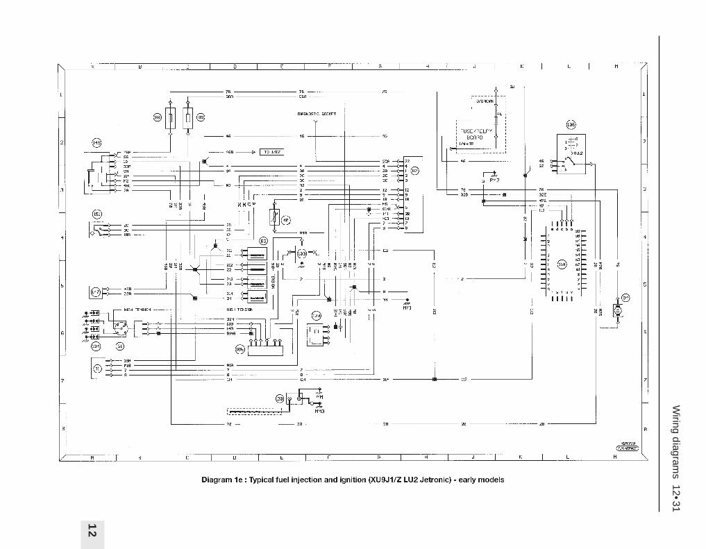
Wiring d
iagrams 12•31
12

12•32W
iring diagram
s

Wiring d
iagrams 12•33
12

12•34W
iring diagram
s

Wiring d
iagrams 12•35
12

12•36W
iring diagram
s

Wiring d
iagrams 12•37
12

12•38W
iring diagram
s

Wiring d
iagrams 12•39
12

12•40W
iring diagram
s

Wiring d
iagrams 12•41
12

BA C D E F G H J K L M
2
1
3
4
5
6
7
8
BA C D E F G H J K L M
2
1
3
4
5
6
7
8
Diagram 1 : Notes, fuses, key to symbols and earth locations - later models
H29180T.M.MARKE
Notes
1. Wire identification is not by colour, but byletters or numbers appearing on the wireat each end.
2. Wires may interconnect between diagramsand are located by using a grid referencee.g. 2/A1 denotes a position on diagram 2grid location A1.
3. Brackets show how circuits may be wiredin more than one way.
4. Not all items are fitted to all models.
Fuse Rating Circuit
F1 10A Radio (accessories +ve)F1A 10A Radio (battery +ve)F2 5A Air conditioning, instrument panel, interior light time delay, selector illuminationF3 SpareF4 10A Lights on buzzer, RH tail lightF5 15A Engine cooling fan/coolant temperature control unit relay, air conditioningF6 10A ABS control unitF7 20A HornF8 ShuntF9 5A LH tail light, front sidelights, sidelight warning light, number plate lightF10 30A Rear electric windowsF11 SpareF12 10A Reversing light, cruise control, handbrake warning light, alarm siren and control unitF13 SpareF14 30A Electric seats, alarmF15 30A Central locking, front/rear interior lights, luggage compartment light, electric aerial,
interior light time delayF16 20A Cigar lighter (battery +ve)F16A 20A Cigar lighter (accessories +ve)F17 SpareF18 10A Rear fog lightsF19 10A Sidelights, instrument panel illumination, dimmer switchF20 30A Heated front seatsF21 30A Air conditioningF22 20A Tailgate wiperF23 15A Heated rear window switchF24 30A Windscreen wipers, supply to control unit cruise control interfaceF25 5A Radio memory, clock, engine cooling fan relay at low rpmF26 30A Hazard warning light switchF27 30A Heated rear screen, heated mirrorsF28 15A Instrument panel, digital clock, height adjustment control unit, stop lights,
differential lock, ride height adjustmentF29 30A Front electric windows, sunroofF30 15A Map reading light, courtesy mirror light, glovebox light, lights on buzzer, indicators,
electric mirror adjustment, electric window one-touch operation, rear electricwindow relay
1 2 3 4 5 6 7 8 10 11 12 13 14 15 169
17 18 19 20 21 22 23 25 26 27 28 29 3024
Passenger compartmentfusebox
Key to symbols
Switch
7
Fuse
Item no.
Pump/motor
Earth
Connecting wiresBulb
3/B2
3/B2
Connection to othercircuits (e.g. diagram3/grid location B2).Direction of arrowdenotes current flow.
Resistor
Variableresistor
Diode
Solenoid actuator
Wire-battery positivepotential (double line)
Wire-battery negativepotential (thick line)
Wire-interconnecting(thin line)
NR2 1
GR1 2
Dashed line denotespart of larger item
M
F13
Earth locations
E000 Near batteryE001 LH side of front panel (in engine compartment)E002 RH side of front panel (in engine compartment)E005 LH side of bulkhead (in engine compartment)E006 RH side of parcel shelfE020 LH kick panel (in passenger compartment)E040 On gearboxE050 Centre of rear panel (in luggage compartment)E052 Inside tailgate (estate)E053 LH rear corner of luggage compartment (estate)E054 RH rear corner of luggage compartment (estate)E081 LH side of bulkhead (in engine compartment)
12•42W
iring diagram
s

BA WhiteGR GreyMR BrownBE BlueRS PinkVE Green
Connector coloursBG BeigeJN YellowRG RedOR OrangeVI MauveNR Black
21
BA C D E F G H J K L M
2
1
3
4
5
6
7
8
BA C D E F G H J K L M
2
1
3
4
5
6
7
8
Diagram 2 : Starting, charging and preheating - later models
H29181T.M.MARKE
G
3
Starting andcharging system -
manual transmissionpetrol models
1
E000
M
Key to items1 Battery2 Battery +ve control unit3 Fusebox4 Ignition switch5 Instrument cluster
a = no charge warning lightb = tachometerc = water in fuel warning lightd = glow plug warning light
6 Alternator7 Starter motor8 Starter inhibitor switch/reversing
light switch (automatic transmission)9 Starter safety relay10 Water in fuel sensor11 TDC sensor12 Fuel cut off solenoid valve13 Preheat control unit14 Glow plugs
21GRNR
412 21
1
4BGR
F28
MR
2
BB5
BB10 AA2
7 8 VE
a
A28
BB
17
BB
18
100
100
1070
1070
5
76
21
G
3
Starting and charging system - automatictransmission petrol models
1
E000
M
21GRNR
4
12 21
1
4BGR
F28
MR
2
BB5
BB10
AA2
7 8 VE
a
A28
BB
17
BB
18
100
108
1070
1070
576
6BRG
F12
BE1A
109
CC2
NR2B 1A
1 2 5 4 3VI
E040
MP
M106
C128
C12
106
108
108
108
8
9
21
G
3
Starting, charging and preheatingsystem - non turbo diesel
1
E000
M
21GRNR 4
12 21
1
GR
F28
MR
2
BB5
BB10
AA2
87
VE
a
BE
JN
BA
93
24
b
c d5
A28
100
1070
76
6BRG
F12
BE1A
CC2CC
CC
1070
4B 2B
3 51 4
118
E020 MPB
M4C
M4BC120
C120
A281070
C120
1070A28
74
6
31 2MR
426428429 427D428
E005
MP
R1
E040
MP
M115VE
CC5CC5
105 105
435BB
18
BB
18
1070
100
BB
15
BB15
BB15
BB
15
CC6
13 2NR M
405
403
403C
12C
129
12
11
10
13
14
GR
GR
GR4/K61030
1030 4/K6
Wiring d
iagrams 12•43
12

VE21
5 24 13 VI
BA C D E F G H J K L M
2
1
3
4
5
6
7
8
BA C D E F G H J K L M
2
1
3
4
5
6
7
8
Diagram 3 : Preheating (turbo diesel) and engine cooling fans -later models
H29182T.M.MARKE
Key to items
1 Battery2 Battery +ve control unit
a = engine cooling fan fuse(s)3 Fusebox4 Ignition switch5 Instrument cluster
a = no charge warning lightb = tachometerc = water in fuel warning lightd = glow plug warning light
6 Alternator7 Starter motor10 Water in fuel sensor11 TDC sensor13 Preheat control unit14 Glow plugs15 Diesel advance corrector relay
16 Post heat thermal switch17 Post heat relay18 Diesel pump (advance corrector/
fuel cut off solenoid)19 Cooling fan relay20 Cooling fan thermal switch21 Cooling fan22 Two speed fan resistor
BA WhiteGR GreyMR BrownBE BlueRS PinkVE Green
Connector colours
BG BeigeJN YellowRG RedOR OrangeVI MauveNR Black
21
G
3
Starting,charging andpreheating system - turbo diesel
1
E000
M
21GRNR
4
12 21
1
GR
F28
MR
2
BB5
BB10
AA2
87
VE
aBE
JN
BA
93
24
b
c d
5
A28
100
1070
76
6BRG
F12
BE1A
CC2CC
1070
4B 2B
118
E020 MPB
M4C
M4BC120
C120
A281070
C120
1070A28
74
6
31 2MR
426428429 427D428
E005
MP
R1
E040
MP
M115VE
CC5CC5
105 105
435BB
18
BB
18
1070
100
BB
15
BB15
BB15
BB
15
13 2NR M
405
403
403C
12C
129
11
10
1314
52 41 3VI
21 3 NRBE21
M11A/M120M11A/M120
M11A
M120
1395
1397 1397
1396
3 51 4 21395
1394
1394
403
CC
14
CC
12C
C6
CC
16
13981398C
C15
16
15
17
18
21
1
E000
2
BE321 1 3 2
NR
1 2NR
M
E001
52 41 3NR
M150
M15E
157
153
1540
B40B
401/B40
152
Single cooling fan
GR
MR
a
1
E000
2
MR
a a
NR 5 24 13 NR 5 24 13 NR 5 24 13
1 2NR
M
1 2NR
M
BE3 2 1
Twin cooling fans
E001
M15D
E002
M15B
156
1550
M15A
154
158
157M
15B
MMC1M15D
159
12
B40
B412
B41
B413
B411
B41/B410B40
159
157
19
21
19 19 19
21
21
22
20
20
12•44W
iring diagram
s

BA WhiteGR GreyMR BrownBE BlueRS PinkVE Green
Connector colours
BG BeigeJN YellowRG RedOR OrangeVI MauveNR Black
BA C D E F G H J K L M
2
1
3
4
5
6
7
8
BA C D E F G H J K L M
2
1
3
4
5
6
7
8
Diagram 4 : Engine systems (carburettor models) - later models
H29183T.M.MARKE
21
3
Engine systems - carburettormodels without submerged pump
1
E000
21GRNR
4
12 21
2
BB5
BB10
2BGR
F12
BE1A
CC
2C
C
GR
BE
JN
BA
7
4
b
e
64
5
E020
MPB
M4B
C120
420 1 2 34
HT 1
BE
32 1NR
32 1 4NR
1VE
427
E005
MPR1
427
110
E040
MP427110
CC
21/CC
20
CC21
CC1 CC1
CC
1
Key to items
1 Battery2 Battery +ve control unit3 Fusebox4 Ignition switch5 Instrument cluster
b = tachometere = choke warning light
23 Choke switch24 Ignition module25 Distributor26 Spark plugs27 Ignition coil28 Carburettor breather solenoid29 Carburettor/throttle housing
heater30 Idle speed solenoid31 Fuel pump fuse32 Fuel pump relay33 Fuel pump34 Oil pressure switch
23
26
25
24
27 28
29
21
3
Engine systems - carburettormodels with submerged pump
1
E000
21GRNR
4
12 21
2
BB5
BB10
2BGR
F12
BE1A
CC
2C
C
GR
BE
JN
BA
7
4
b
e
64
5
E020
MPB
M4B
C120
420 1 2 34
HT 1
BE
32 1NR
32 1 4NR
1VE
427
E005
MPR1
427
110
E040
MP
427110
CC
21/CC
20
CC21
CC1 CC1C
C1
23
26
25
24
27 28
29
NR 52 41 3NR21
M
E050
M121
121
2/G2
1030
C501
CC20
CC
20/CC
22
RG12
8073
From airconditioning
M801
M801M
801
2GR
410
4120
4120
410
30
34
31 32
33
5/L61202
2/C2
5/M
3
Wiring d
iagrams 12•45
12

E014
BA21 BA 2 1
E015
VE12
BE21
BA WhiteGR GreyMR BrownBE BlueRS PinkVE Green
Connector coloursBG BeigeJN YellowRG RedOR OrangeVI MauveNR Black
BA C D E F G H J K L M
2
1
3
4
5
6
7
8
BA C D E F G H J K L M
2
1
3
4
5
6
7
8
Diagram 5 : Warning lights and gauges - later models
H29184T.M.MARKE
Key to items1 Battery2 Battery +ve control unit3 Fusebox4 Ignition switch5 Instrument cluster
f = coolant temp. gaugeg = oil temp./level gaugeh = high coolant temp. warning lighti = oil pressure gaugej = stop warning lightk = pad wear warning lightl = catalytic converter warning light
m = handbrake/low brake fluidwarning light
n = low oil pressure warning lighto = low coolant warning lightp = fuel gaugeq = low fuel warning lightr = fuel gauge (submerged pump)s = low fuel warning light
(submerged pump)35 Engine oil level sensor36 Engine oil temperature sensor
37 Coolant temperature sensor/switch38 LH front pad wear sensor39 RH front pad wear sensor40 Oil pressure sensor/switch41 Fuel gauge sender unit42 Fuel gauge sender unit
(submerged pump)43 Catalytic converter temperature sensor44 Catalytic converter temperature control unit45 Low brake fluid sender unit46 Handbrake switch47 Coolant level sensor
21
3
1
E000
21GRNR
4
12 21
2
BB5
BB10
GR
F12
BE1A
CC
2C
C
GR
F2
2B3BRG
6B
BA
VEJN
f
h j o
JN47 6
E020
M4E
MP
BC
O23
401
CO
23 401400
400
C120
NR
32
1
E002
402
C123
g
BE32 14
42
M4C
M4B
C120
n
C120M4C
MM
C2
M401
402
402
GR21
412
410
410412
BE12
411
411
414415
415414
i
p
96 4
q
MR312
E050
M430
430
430
431
431
r
s
MR
M
12 3 4 5
}
430M
430
M120
M120
4/M
61202
430
k m
8/H2
211444
446
412402431
445
446
21NR
21NR
M44B
M44A
M440
M440
E005
MP
R1
M441
441441
440
4410
C12
3 21NR
l
24 7 10 9 118
GR
MPR2
M480
485485
485C121
402
5
441485
485441
M440
485441
M440
35 36 37
38 3940 41 42
43
44
45 46
47
4/L8410
12•46W
iring diagram
s

21MR
21
BA C D E F G H J K L M
2
1
3
4
5
6
7
8
BA C D E F G H J K L M
2
1
3
4
5
6
7
8
Diagram 6 : External temp. display, clock and exterior lighting - later models
H29185T.M.MARKE
3
1
6AGR
F25
NR
F8
1
E000
Key to items1 Battery2 Battery +ve control unit3 Fusebox4 Ignition switch5 Instrument cluster
t = analogue clocku = sidelight warning light
48 Outside air temp. display49 Digital clock50 Outside air temp. sensor51 Multi-function switch52 Horn53 RH front sidelight54 LH front sidelight55 Number plate light
56 RH rear light cluster (saloon)a = direction indicatorb = tail lightc = brake lightd = foglighte = reversing light
57 LH rear light cluster (saloon)(see above)
BA WhiteGR GreyMR BrownBE BlueRS PinkVE Green
Connector coloursBG BeigeJN YellowRG RedOR OrangeVI MauveNR Black
2
NR
BB
1
BA
t1 2
5
E020
B252
M4C
MP
B
Analogue clock
21
1
E000
21GRNR
12 21
4
2
BB5
BB10
AA
2GR
3
1
F25
NR
F8
1
GR
F28
MR
6A 5B
Digital clock/outsideair temp. display
NR
21 BB1
21 3 4 5 6 7GR
21 3 4GR
BA21
B251
B253
B253
721722
721722
A283
A285
A285
8/C
3V
193
A283
B251
V196
V19B
E020
MP
BM
722
M72A
3A1ABA
NR12
21
3
1
5AVE
F7
NR
1
2
NR
250
12NR
E000
E001 E002
MM
C1
MM
C2
M250
M251
251
252
BB1
BO
7
Horns
48
49
50
51
52 52
BA3B2B
51
21
1
E000
2GR
BB5 BB7
MR
234
56
1
MR
543
21
6
MR
21
3GR
F9
RG VE
F4 BE
7B
2B2A
1B
VV1
VV
7
MV2
MV1 MV1V094
V095
V094
21MR
Side, tail and numberplate lights (saloon)
VO9VO4
E050
M26A
M26B
21
MR
21
MR
V092
V091
E001
MMC1 MV2
MV1
E002
MMC2
VO4
VO9
V090
2BA
1
JN u
E002
V096 M4C
MPB
VO9VO4
V094MV1
5
53
54
55
55
56
57
a
b
c
d
e
a
b
c
d
e
VO
4
Wiring d
iagrams 12•47
12

RC
MNR
Main
Dip
NR
1
E002
MMC2
MPR9
MP2
MPR8
MP1
PC3
PC4PR4
PR3
PR9
PR8
E001
MMC1
BA C D E F G H J K L M
2
1
3
4
5
6
7
8
BA C D E F G H J K L M
2
1
3
4
5
6
7
8
Diagram 7 : Exterior lighting continued - later models
H29186T.M.MARKE
Key to items1 Battery2 Battery +ve control unit3 Fusebox4 Ignition switch5 Instrument cluster
v = dip beam warning lightw = main beam warning light
51 Multi-function switch55 Number plate light58 RH tailgate light cluster (estate)
d = foglighte = reversing light
59 LH tailgate light cluster (estate)(see above)
60 RH headlight61 RH driving light62 LH driving light63 LH headlight
64 Dim-dip relay B65 Driving light relay66 Dim-dip relay A67 Dim-dip resistor73 RH rear light cluster (estate)
a = direction indicatorb = tail lightc = brake light
74 LH rear light cluster (estate)(see above)
BA WhiteGR GreyMR BrownBE BlueRS PinkVE Green
Connector coloursBG BeigeJN YellowRG RedOR OrangeVI MauveNR Black
BA3B2B
51
21
1
E000
2GR
BB5
VO9D
3
F9
RG VE
F4 BE
2B2A
1B
VV1
VV
7
Tail and numberplate lights (estate)
BE
2
14
3
a
b
c
BE
2
14
3
a
b
c
BE
d
e
MR
21
4
12
3 MR
21
M26A
BE
d
e
MR
21
1
43
2
MR
21
M26VO9G
3 4 12BE
M95
VO
95
VO4 VO4E054
M26A
VO9VO94VO9
VO
4V
O9
M268BM94
E052
E053
MV
21
1
E000
21GRNR
4
12 21
2
BB5
BB10
GR
JN54
BAJN22
v w
E020
MP
BM
4CM
4E
6BRGF12BE
1A
CC
2
CC
BA3B2B1B
51
NR3B2B5B 1A
BB
6
BB
9
BB
8
BB
5
NR
1
RC
MNR
Main
Dip
1
2
5
43
MR
5
2
1
3
VE
3
2
1
NR
E005
M240MPR2
M268MPR1
245
C12
C122
PC
1
PR
5
PC1
VV
1
VV1
PR10
246
PC7PC7
PC
5
BB
19
BB17
BB18
PR7
PR7
BB19
PC1
PR11
245PR10
PC
5
PR
1
PR1
PR5
5
2
1
3
VE
Headlights
73
58
55
55
74
59
5
3
60
61
62
63
64
65
66
67
BB7
12•48W
iring diagram
s

MR
234
56
1
MR
543
21
6
MR
21
E050
M26A
M26B
56
57
a
b
c
d
e
a
b
c
d
e
BE
d
e
MR
21
4
12
3
BE
d
e
MR
21
1
43
2
3 4 12BE
M95203
58
59
E052
M94
}
202
202
202
E002
BA C D E F G H J K L M
2
1
3
4
5
6
7
8
BA C D E F G H J K L M
2
1
3
4
5
6
7
8
Diagram 8 : Exterior lighting continued - later models
H29187T.M.MARKE
21
1
E000
2
GR
BA3B2B1B
NR1B
51
NR
1
MMC2
MPB6
3
F19
F18BEVE
2A1B
5B3B
JN
x
48
5
5
2
1
3
VE
BA2B4B4A2A3B5B1B1A
BA
5B4B3B1B
E001
MMC1
MPB5NR
1 MP5
MP6
E020
M26A
MP
8
M4E
MV5
M26B
M200
202
PB1
PB1
BB
5
BB
7B
B6
BB4
RC
VV
1
VV3
V197
200200
V19F V19D
V193/V197
MP
5
PB
4
PB4/PB5
PB3
201
201
Front and rear foglights
BA WhiteGR GreyMR BrownBE BlueRS PinkVE Green
Connector coloursBG BeigeJN YellowRG RedOR OrangeVI MauveNR Black
Key to items1 Battery2 Battery +ve control unit3 Fusebox4 Ignition switch5 Instrument cluster
x = foglight warning light8 Starter inhibitor switch/reversing
light switch (automatic trans.)51 Multi-function switch56 RH rear light cluster (saloon)
(see diagram 6)57 LH rear light cluster (saloon)
(see diagram 6)58 RH tailgate light cluster (estate)
d = foglighte = reversing light
59 LH tailgate light cluster (estate)(see above)
68 LH front foglight69 RH front foglight70 Front foglight switch71 Front foglight relay72 Rear foglight switch73 RH rear light cluster (estate)
a = direction indicatorb = tail lightc = brake light
74 LH rear light cluster (estate)(see above)
75 Reversing light switch (manual trans.)76 Stop light switch
69
68
71
70
72
213
1
E000
21GRNR
4
12 21
1
1B MR
F28
MR
2
6BRG
F12
BE1A
CC
2C
C
GR
202
203
BB
10B
B5
AA
2
MR
234
56
1
MR
543
21
6
MR
21
E050
M26A
M26B
56
57
a
b
c
d
e
a
b
c
d
e
BE
2
14
3
a
b
c
BE
2
14
3
a
b
c
BE
d
e
MR
21
4
12
3
BE
d
e
MR
21
1
43
2
3 4 12BE
M95
213E054
M26A
M268B
M94
E052
E053
MV
73
58
75
59
221
214
213
221
213
212
220
MV
BA21
}210
A284
210210NR
2A 1B
8
BA21
}
220
220
220C12
C127220
Stop and reversing lights
76
74
V193
Interiorlighting
feed
5/E3 211
Wiring d
iagrams 12•49
12

MR2 3 1
NR2A5A4A
51
BA C D E F G H J K L M
2
1
3
4
5
6
7
8
BA C D E F G H J K L M
2
1
3
4
5
6
7
8
Diagram 9 : Exterior lighting continued and interior lighting - later models
H29188T.M.MARKE
213
1
E000
21GRNR
412 21
1
1BJN
F30
MR
2
AA
2
VE
F26
NR2
GR
BB
10B
B5
3A
21NR
BB
2
MR
234
56
1
MR
543
21
6
MR
21
E050
M26A
M26B
56
57
a
b
c
d
e
a
b
c
d
e
BE
2
14
3
a
b
c
BE
2
14
3
a
b
c
E054
M26A
M268B
E053
73
74
E001
MMC1M23A
E002
M23B
MMC2
E005
MPR2M233MR
12
MR
12
M234MR
12
BA
3B4A2B5B4B1A1B2A5A
E020
MPB
M23B
MV
19
JN421
y z
JN152
M23AM4E
A306
B26
230231/232
231
232A306230B26
MV19
2344
234/2344
233/2334
2334
V19C2340/23432330/2333
V193
2333
2331
2332
2343
M23BMR
12
2341
2342
2343
2343 (Estate only)
2343 (Estate only)
Direction indicators
Key to items1 Battery2 Battery +ve control unit3 Fusebox4 Ignition switch5 Instrument cluster
y = LH direction indicatorz = RH direction indicator
51 Multi-function switch56 RH rear light cluster (saloon)
a = direction indicatorb = tail lightc = brake lightd = foglighte = reversing light
57 LH rear light cluster (saloon)(see above)
73 RH rear light cluster (estate)a = direction indicatorb = tail lightc = brake light
74 LH rear light cluster (estate)(see above)
77 Direction indicator relay78 Hazard warning switch79 RH front direction indicator80 RH side repeater81 LH side repeater82 LH front direction indicator83 Front roof light84 Rear roof light85 Luggage compartment light86 Luggage compartment light switch87 Interior light door switches
BA WhiteGR GreyMR BrownBE BlueRS PinkVE Green
Connector coloursBG BeigeJN YellowRG RedOR OrangeVI MauveNR Black
5
77
78
79
80
81
82
21
31
7BVE
F15
NR
F8
1
E000
2
NR
BB
1
5ARG
305
306
40
40
300
301
E050
M301
MP
B
E020
M302
MR2 3 1
B153
MR
21
MR
319
B154
B15A
B15B
300M319
M319319
Typical interior light
83 84
85
86
87
8/C
3
12•50W
iring diagram
s

Rear
wash/w
ipe
Frontwash/wipe
GR2B 1A1B3B4A 2A5B6B
BA C D E F G H J K L M
2
1
3
4
5
6
7
8
BA C D E F G H J K L M
2
1
3
4
5
6
7
8
Diagram 10 : Interior lighting continued and front wash/wipe - later models
H29189T.M.MARKE
Key to items1 Battery2 Battery +ve control unit3 Fusebox4 Ignition switch5 Instrument cluster
a1 = instrument illumunation51 Multi-function switch88 Lighting rheostat89 Cigar lighter90 Cigar lighter illumination91 Selector lever illumination
(automatic trans.)92 Map reading light93 Vanity mirror light94 Glovebox light95 Glovebox light switch96 Wash/wipe switch97 Front wiper relay98 Front wiper motor99 Front washer pump
21
1
E000
21GRNR
12 21
4
2
BB5
BB10
AA
2
GR
3
2NR
1
F16A
MR
NR
21 BB2
F16
7AMR
F2
BE1A
CC
2
MR6B
F19
VE2A
BE6A
BA3B2B
51
BB7VV1
VV
3
a1
65BA
5E020
MP
B
MVR4
MR41
VR
VR
4
V19A
1NR
VR
1
}
}
V19A
12BA
M307
C024
13
BA
M810
B16
C024
M810
Interior lighting and cigar lighter
88
89
90
91
21GRNR
12 21
4
BB5
BB10 AA
2
1MR
F30
21
1
E000
2
GR
4BVE
5AMR
MR
12
MR
21
E020
MPB
M311
M306
MR
12
310310
A307
A304
A304
A307
3
MR
A304/A303
BA WhiteGR GreyMR BrownBE BlueRS PinkVE Green
Connector coloursBG BeigeJN YellowRG RedOR OrangeVI MauveNR Black
M306
Map reading light andglovebox illumination
93
92
94
95
21GRNR
12 21
4
BB5
BB10 AA
2
1MR
F24
21
1
E000
2
GR
JN
3
4A5A
14 6 8 5212 4 5 3
BANR2 1
M
NR
502
505
M
A242503
503
E020
M501
MPB
511
510
510/511
500501
A242A240/A241
A240
E005
M510
E006
M501
A241502505500501
Front wash/wipe
MP
R1
9998
96
97
Wiring d
iagrams 12•51
12

BA C D E F G H J K L M
2
1
3
4
5
6
7
8
BA C D E F G H J K L M
2
1
3
4
5
6
7
8
Diagram 11 : Rear wash/wipe, heater blower and heated rear window - later models
H29190T.M.MARKE
Key to items
1 Battery2 Battery +ve control unit3 Fusebox4 Ignition switch51 Multi-function switch88 Lighting rheostat96 Wash/wipe switch100 Rear wiper motor101 Rear wiper relay102 Rear washer pump103 Heated rear window104 Heated rear window switch105 Heated rear window relay106 Heater blower relay107 Heater blower control unit108 Heater blower motor109 Heater blower switch
BA WhiteGR GreyMR BrownBE BlueRS PinkVE Green
Connector coloursBG BeigeJN YellowRG RedOR OrangeVI MauveNR Black
Rear
wash/w
ipe
Frontwash/wipe
GR2B 1A1B3B4A 2A5B6B
21GRNR
12 21
4
BB5
BB10 AA
2
1MR
F24
21
1
E000
2
GR
JN
3
4
1
3
2
BA
M
NR2 1
M
A241
E054
M530
Rear wash/wipe (estate)
96
F12
5A 1A
52 41 3NR
A22
A221
522521
A22
530520
E053
MV
M521
M520
520
530
A241
A241
100
101
102
21GRNR
12 21
4
MR
F5
21
1
E000
2
GR
GR
3 F21
BB5
2
1ARG
5A 7A
BE5A
BB15
KK
1
BA3B2B
51
BB11
BB7
F19
VE2A
BE6A
VV
1
VV3
5
2
4
1
3
JN
E020
MPB
M804K051
K05/K
051
B210
B211
MR
M
23 14
M805
13
803
NR2B 3B4A1B2A1A
8 7 7 8 62
2
MR41
88
VR
}
V19A
}}
54
V19A
/V19T
4 5
Heater blower
21
1
E000
21GRNR
12 21
4
2
BB5
BB10
GR
3
1
F27
NR2
F23
MR
NR
21 BB1
BB11
1AMR 4B
4B
KK
1
5
2
1
3
VE
E020
MPB
M81A
B27
E081
M811
MR
5B
1B2B3B
4B
M81B
K23
810
K23
811810K23
812
8111
8/C
3V
19E
V19E
V193
K23
8111810
8108111B27
103
104
105
106
107
108
109Heated rear window
12/A6
813
12•52W
iring diagram
s

BA C D E F G H J K L M
2
1
3
4
5
6
7
8
BA C D E F G H J K L M
2
1
3
4
5
6
7
8
Diagram 12 : Electric mirrors, radio/cassette and lights on buzzer - later models
H29191T.M.MARKE
Key to items
1 Battery2 Battery +ve control unit3 Fusebox4 Ignition switch51 Multi-function switch87 Interior light door switches110 Electric mirror control switch111 LH mirror assembly112 RH mirror assembly
113 Electric aerial114 Radio/cassette unit115 LH front speaker116 LH front tweeter117 RH front speaker118 RH front tweeter119 LH rear speaker120 RH rear speaker121 Lights on buzzer
BA WhiteGR GreyMR BrownBE BlueRS PinkVE Green
Connector coloursBG BeigeJN YellowRG RedOR OrangeVI MauveNR Black
21GRNR
12 21
4
BB5
BB10
AA
2
1MR
F30
21
1
E000
2
GR
MR
3
Electric mirrors
4B
M M
1 2 3 4 5BA
MM
12345BA
E020
MP
B
M814 M813
M640
6401
64126401
A301
4
2 2
75
6
143
NR
GR
M640
6412
6401
813
814
813
813
V193
V190
64026400
641
6411
6411
6411
6402
641
640
641
6401813
6411641
AA2
110
111 112
21
1
E000
21GRNR
12 21
4
2
BB5
BB10
AA2GR
3
1
F25
NR
F8
1
BE
F1
MR
NR
21 BB1
F15 F1A
7B 2ARG 5A
4
78
6
52
43
1
7856
21
JNNR
BA(NR)
21
MR
21
MR
21
JN
12
BA
8431 841
843
8441
844
842
12
BA
847848845846
846845
843844
841842
84218411
21
3
BA
840
B520
A01
8/C3 V193
V199A01
E020
M841
E050
M840
A01B520
B154
B15C840
Radio/cassette
113
114 120
119
118
117
115
116
B520840
305
306
307
308
87
3071
3092
21
1
E000
21GRNR
12 21
4
2
BB5
BB10
AA
2
GR
3
1MR
F30
MR
F4
RG2A
BA3B2B
51
BB7
VV1
VV
7
5B 2B
Lights on buzzer
25
1
BA
VO4VA30
304
304
121
11/D
5
8/C
3
13/J
3305
304
304
Wiring d
iagrams 12•53
12

12•54W
iring diagram
s
BA C D E F G H J K L M
2
1
3
4
5
6
7
8
BA C D E F G H J K L M
2
1
3
4
5
6
7
8
Diagram 13 : Central locking and electric windows - later models
H29192T.M.MARKE
1 Battery2 Battery +ve control unit3 Fusebox4 Ignition switch122 Door locking control unit123 Infra red receiver124 RH front door lock125 LH front door lock126 RH rear door lock127 LH rear door lock128 Tailgate lock motor
129 Fuel filler lock motor130 Electric window and sunroof relay131 Electric window and sunroof
reconnection relay132 Instantaneous electric window unit133 RH front window motor134 RH door switch for RH window135 RH door switch for LH window136 LH door switch for LH window137 LH front window motor
Key to items
21
31
7A 7BVE
F15
NR
F8
1
E000
2
NR
BB
1
21
78
NR
1 2MR
M
MRM
12
321
BA
4
1
6
9
MR
7
5
8
3
2
1 2BA
M
1 2MR
M
MR
M
12
321
BA
B153
B152
B151
627628
628627
E020
MPB M623
M623
M623
M620
6251
6252
M620
6251
6252
6251
6231
M620
6231
623162526232
M620
628
627
621
6212
621
6211
1 2BA
M
6213
6216
6215
6213
6202 6201
620
620
6203
6206
6205
6203
123
122
125
124
127 128 129 126
Central locking
21
1
E000
21GRNR
12 21
4
2
BB5
BB10
AA2GR
3F29
NR
F8
1
MR
F28
MR
NR
21 BB1
F15
2 1
BB2
F30
3A 6A7B 2A 4B NR52 41 3
NR52 31
B155B156
A282
12/M
5305
601
B29 B29
M 6050
6040
60516052
60426041
2
1
GR
4A
1A
3B
2A
2B4B
5A
5B1B
RG
4
5
2
6
3
7
BE
A302
A301
6001600
M600
M603
600560526051
A30160406050
M602
E020
MPB
43
5
2
1MR
M12
GR
608
607
606
6002
6003
M606
M607 43
5
2
1
MR
609
608
609
606
607
Electric windows
BA WhiteGR GreyMR BrownBE BlueRS PinkVE Green
Connector coloursBG BeigeJN YellowRG RedOR OrangeVI MauveNR Black
130
131
132
133
134
135
136
137

Dimensions and Weights . . . . . . . . . . . . . . . . . . REF•1Conversion Factors . . . . . . . . . . . . . . . . . . . . . . . REF•2Buying Spare Parts . . . . . . . . . . . . . . . . . . . . . . .REF•3Vehicle Identification . . . . . . . . . . . . . . . . . . . . . . REF•3General Repair Procedures . . . . . . . . . . . . . . . . . REF•4Jacking and Vehicle Support . . . . . . . . . . . . . . . REF•5
Radio/cassette unit Anti-theft System . . . . . . . . REF•5Tools and Working Facilities . . . . . . . . . . . . . . . . REF•6MOT Test Checks . . . . . . . . . . . . . . . . . . . . . . . .REF•8Fault Finding . . . . . . . . . . . . . . . . . . . . . . . . . . . REF•12Glossary of Technical Terms . . . . . . . . . . . . . . . REF•20Index . . . . . . . . . . . . . . . . . . . . . . . . . . . . . . . . . REF•25
Reference REF•1
REF
Dimensions and weightsNote: All figures are approximate, and may vary according to model.Refer to manufacturer’s data for exact figures.
DimensionsOverall length:
Saloon . . . . . . . . . . . . . . . . . . . . . . . . . . . . . . . . . . . . . . . . .4408 mmEstate . . . . . . . . . . . . . . . . . . . . . . . . . . . . . . . . . . . . . . . . .4398 mm
Overall width:Saloon . . . . . . . . . . . . . . . . . . . . . . . . . . . . . . . . . . . . . . . . .1714 mmEstate . . . . . . . . . . . . . . . . . . . . . . . . . . . . . . . . . . . . . . . . .1707 mm
Overall height (unladen):Saloon . . . . . . . . . . . . . . . . . . . . . . . . . . . . . . . . . . . . . . . . .1406 mmEstate . . . . . . . . . . . . . . . . . . . . . . . . . . . . . . . . . . . . . . . . .1445 mm
Wheelbase:All models . . . . . . . . . . . . . . . . . . . . . . . . . . . . . . . . . . . . . .2669 mm
WeightsKerb weight:
Saloon . . . . . . . . . . . . . . . . . . . . . . . . . . . . . . . . . . .1030 to 1100 kg*Estate . . . . . . . . . . . . . . . . . . . . . . . . . . . . . . . . . . .1090 to 1160 kg*
Maximum gross vehicle weight:Saloon . . . . . . . . . . . . . . . . . . . . . . . . . . . . . . . . . . .1470 to 1580 kg*Estate . . . . . . . . . . . . . . . . . . . . . . . . . . . . . . . . . . .1590 to 1660 kg*
Maximum towing weight:Unbraked trailer:
Saloon . . . . . . . . . . . . . . . . . . . . . . . . . . . . . . . . . . .515 to 560 kg*Estate . . . . . . . . . . . . . . . . . . . . . . . . . . . . . . . . . . . .540 to 580 kg*
Braked trailer:Saloon . . . . . . . . . . . . . . . . . . . . . . . . . . . . . . . . . .900 to 1200 kg*Estate . . . . . . . . . . . . . . . . . . . . . . . . . . . . . . . . . . . . . . . . .1200 kg
Maximum trailer nose weight . . . . . . . . . . . . . . . . . . . . . . . . . . . . .65 kg*Depending on model and specification.
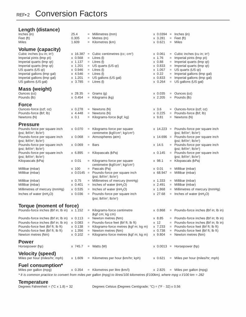
REF•2 Conversion Factors
Length (distance)Inches (in) 25.4 = Millimetres (mm) x 0.0394 = Inches (in)Feet (ft) 0.305 = Metres (m) x 3.281 = Feet (ft)Miles 1.609 = Kilometres (km) x 0.621 = Miles
Volume (capacity)Cubic inches (cu in; in3) x 16.387 = Cubic centimetres (cc; cm3) x 0.061 = Cubic inches (cu in; in3)Imperial pints (Imp pt) x 0.568 = Litres (l) x 1.76 = Imperial pints (Imp pt)Imperial quarts (Imp qt) x 1.137 = Litres (l) x 0.88 = Imperial quarts (Imp qt)Imperial quarts (Imp qt) x 1.201 = US quarts (US qt) x 0.833 = Imperial quarts (Imp qt)US quarts (US qt) x 0.946 = Litres (l) x 1.057 = US quarts (US qt)Imperial gallons (Imp gal) x 4.546 = Litres (l) x 0.22 = Imperial gallons (Imp gal)Imperial gallons (Imp gal) x 1.201 = US gallons (US gal) x 0.833 = Imperial gallons (Imp gal)US gallons (US gal) x 3.785 = Litres (l) x 0.264 = US gallons (US gal)
Mass (weight)Ounces (oz) x 28.35 = Grams (g) x 0.035 = Ounces (oz)Pounds (lb) x 0.454 = Kilograms (kg) x 2.205 = Pounds (lb)
ForceOunces-force (ozf; oz) x 0.278 = Newtons (N) x 3.6 = Ounces-force (ozf; oz)Pounds-force (lbf; lb) x 4.448 = Newtons (N) x 0.225 = Pounds-force (lbf; lb)Newtons (N) x 0.1 = Kilograms-force (kgf; kg) x 9.81 = Newtons (N)
PressurePounds-force per square inch x 0.070 = Kilograms-force per square x 14.223 = Pounds-force per square inch(psi; lbf/in2; lb/in2) centimetre (kgf/cm2; kg/cm2) (psi; lbf/in2; lb/in2)Pounds-force per square inch x 0.068 = Atmospheres (atm) x 14.696 = Pounds-force per square inch(psi; lbf/in2; lb/in2) (psi; lbf/in2; lb/in2)Pounds-force per square inch x 0.069 = Bars x 14.5 = Pounds-force per square inch(psi; lbf/in2; lb/in2) (psi; lbf/in2; lb/in2)Pounds-force per square inch x 6.895 = Kilopascals (kPa) x 0.145 = Pounds-force per square inch(psi; lbf/in2; lb/in2) (psi; lbf/in2; lb/in2)Kilopascals (kPa) x 0.01 = Kilograms-force per square x 98.1 = Kilopascals (kPa)
centimetre (kgf/cm2; kg/cm2)Millibar (mbar) x 100 = Pascals (Pa) x 0.01 = Millibar (mbar)Millibar (mbar) x 0.0145 = Pounds-force per square inch x 68.947 = Millibar (mbar)
(psi; lbf/in2; lb/in2)Millibar (mbar) x 0.75 = Millimetres of mercury (mmHg) x 1.333 = Millibar (mbar)Millibar (mbar) x 0.401 = Inches of water (inH2O) x 2.491 = Millibar (mbar)Millimetres of mercury (mmHg) x 0.535 = Inches of water (inH2O) x 1.868 = Millimetres of mercury (mmHg)Inches of water (inH2O) x 0.036 = Pounds-force per square inch x 27.68 = Inches of water (inH2O)
(psi; lbf/in2; lb/in2)
Torque (moment of force)Pounds-force inches (lbf in; lb in) x 1.152 = Kilograms-force centimetre x 0.868 = Pounds-force inches (lbf in; lb in)
(kgf cm; kg cm)Pounds-force inches (lbf in; lb in) x 0.113 = Newton metres (Nm) x 8.85 = Pounds-force inches (lbf in; lb in)Pounds-force inches (lbf in; lb in) x 0.083 = Pounds-force feet (lbf ft; lb ft) x 12 = Pounds-force inches (lbf in; lb in)Pounds-force feet (lbf ft; lb ft) x 0.138 = Kilograms-force metres (kgf m; kg m) x 7.233 = Pounds-force feet (lbf ft; lb ft)Pounds-force feet (lbf ft; lb ft) x 1.356 = Newton metres (Nm) x 0.738 = Pounds-force feet (lbf ft; lb ft)Newton metres (Nm) x 0.102 = Kilograms-force metres (kgf m; kg m) x 9.804 = Newton metres (Nm)
PowerHorsepower (hp) x 745.7 = Watts (W) x 0.0013 = Horsepower (hp)
Velocity (speed)Miles per hour (miles/hr; mph) x 1.609 = Kilometres per hour (km/hr; kph) x 0.621 = Miles per hour (miles/hr; mph)
Fuel consumption*Miles per gallon (mpg) x 0.354 = Kilometres per litre (km/l) x 2.825 = Miles per gallon (mpg)
* It is common practice to convert from miles per gallon (mpg) to litres/100 kilometres (l/100km), where mpg x l/100 km = 282
TemperatureDegrees Fahrenheit = (°C x 1.8) + 32 Degrees Celsius (Degrees Centigrade; °C) = (°F - 32) x 0.56

Spare parts are available from many sources,including maker’s appointed garages, accessoryshops, and motor factors. To be sure ofobtaining the correct parts, it may sometimes benecessary to quote the vehicle identificationnumber. If possible, it can also be useful to takethe old parts along for positive identification.Items such as starter motors and alternatorsmay be available under a service exchangescheme - any parts returned should be clean.
Our advice regarding spare part sources isas follows.
Officially-appointed garagesThis is the best source of parts which are
peculiar to your car, and are not otherwisegenerally available (eg badges, interior trim,certain body panels, etc). It is also the onlyplace at which you should buy parts if thevehicle is still under warranty.
Accessory shopsThese are good places to buy materials and
components needed for the maintenance ofyour car (oil, air and fuel filters, spark plugs,light bulbs, drivebelts, oils and greases, brakepads, touch-up paint, etc). Parts like this soldby a reputable shop are of the same standardas those used by the car manufacturer.
Motor factorsGood factors will stock all the more
important components which wear outcomparatively quickly and can sometimessupply individual components needed for theoverhaul of a larger assembly. They may alsohandle work such as cylinder block reboring,crankshaft regrinding and balancing, etc.
Tyre and exhaust specialistsThese outlets may be independent or
members of a local or national chain. Theyfrequently offer competitive prices whencompared with a main dealer or local garage,but it will pay to obtain several quotes beforemaking a decision. Also ask what ‘extras’ maybe added to the quote - for instance, fitting anew valve and balancing the wheel are bothoften charged on top of the price of a newtyre.
Other sourcesBeware of parts or materials obtained from
market stalls, car boot sales or similar outlets.Such items are not invariably sub-standard,but there is little chance of compensation ifthey do prove unsatisfactory. In the case ofsafety-critical components such as brakepads there is the risk not only of financial lossbut also of an accident causing injury ordeath.
Buying Spare Parts REF•3
REF
Vehicle identification numbersModifications are a continuing and
unpublicised process in vehicle manufacture,quite apart from major model changes. Spareparts lists are compiled upon a numericalbasis, the individual vehicle identificationnumbers being essential to correct identifi-cation of the component concerned.
When ordering spare parts, always give asmuch information as possible. Quote the carmodel, year of manufacture, body and enginenumbers, as appropriate.
The Vehicle Identification Number (VIN)plate is riveted to the top of the front crosspanel in the engine compartment. It is alsostamped into the right-hand side of the enginebulkhead.
The Engine number is situated on the frontof the cylinder block, just below the cylinderhead. On TU engines it is near the left-handend of the engine, on XU10 engines it is mid-way, and on XU5, XU7 and XU9 engines it ison the right-hand end. Note: The first part ofthe engine number gives the engine code - eg, “XU5”.
The Vehicle paint code is stamped into theleft-hand inner wing panel.
Other identification numbers or codes arestamped on major items such as the gearbox,final drive housing, distributor etc.
Location of Vehicle Identification Plates
1 Vehicle identification plate2 Vehicle identification number3 Vehicle paint colour code

Whenever servicing, repair or overhaul workis carried out on the car or its components, itis necessary to observe the followingprocedures and instructions. This will assist incarrying out the operation efficiently and to aprofessional standard of workmanship.
Joint mating faces and gasketsWhen separating components at their
mating faces, never insert screwdrivers orsimilar implements into the joint between thefaces in order to prise them apart. This cancause severe damage which results in oilleaks, coolant leaks, etc upon reassembly.Separation is usually achieved by tappingalong the joint with a soft-faced hammer inorder to break the seal. However, note thatthis method may not be suitable wheredowels are used for component location.
Where a gasket is used between the matingfaces of two components, ensure that it isrenewed on reassembly, and fit it dry unlessotherwise stated in the repair procedure. Makesure that the mating faces are clean and dry,with all traces of old gasket removed. Whencleaning a joint face, use a tool which is notlikely to score or damage the face, and removeany burrs or nicks with an oilstone or fine file.
Make sure that tapped holes are cleanedwith a pipe cleaner, and keep them free ofjointing compound, if this is being used,unless specifically instructed otherwise.
Ensure that all orifices, channels or pipesare clear, and blow through them, preferablyusing compressed air.
Oil sealsOil seals can be removed by levering them
out with a wide flat-bladed screwdriver orsimilar tool. Alternatively, a number of self-tapping screws may be screwed into the seal,and these used as a purchase for pliers orsimilar in order to pull the seal free.
Whenever an oil seal is removed from itsworking location, either individually or as partof an assembly, it should be renewed.
The very fine sealing lip of the seal is easilydamaged, and will not seal if the surface itcontacts is not completely clean and free fromscratches, nicks or grooves. If the originalsealing surface of the component cannot berestored, and the manufacturer has not madeprovision for slight relocation of the sealrelative to the sealing surface, the componentshould be renewed.
Protect the lips of the seal from any surfacewhich may damage them in the course offitting. Use tape or a conical sleeve wherepossible. Lubricate the seal lips with oil beforefitting and, on dual-lipped seals, fill the spacebetween the lips with grease.
Unless otherwise stated, oil seals must befitted with their sealing lips toward thelubricant to be sealed.
Use a tubular drift or block of wood of theappropriate size to install the seal and, if theseal housing is shouldered, drive the sealdown to the shoulder. If the seal housing is
unshouldered, the seal should be fitted withits face flush with the housing top face (unlessotherwise instructed).
Screw threads and fasteningsSeized nuts, bolts and screws are quite a
common occurrence where corrosion has setin, and the use of penetrating oil or releasingfluid will often overcome this problem if theoffending item is soaked for a while beforeattempting to release it. The use of an impactdriver may also provide a means of releasingsuch stubborn fastening devices, when usedin conjunction with the appropriatescrewdriver bit or socket. If none of thesemethods works, it may be necessary to resortto the careful application of heat, or the use ofa hacksaw or nut splitter device.
Studs are usually removed by locking twonuts together on the threaded part, and thenusing a spanner on the lower nut to unscrewthe stud. Studs or bolts which have broken offbelow the surface of the component in whichthey are mounted can sometimes be removedusing a stud extractor. Always ensure that ablind tapped hole is completely free from oil,grease, water or other fluid before installingthe bolt or stud. Failure to do this could causethe housing to crack due to the hydraulicaction of the bolt or stud as it is screwed in.
When tightening a castellated nut to accepta split pin, tighten the nut to the specifiedtorque, where applicable, and then tightenfurther to the next split pin hole. Neverslacken the nut to align the split pin hole,unless stated in the repair procedure.
When checking or retightening a nut or boltto a specified torque setting, slacken the nutor bolt by a quarter of a turn, and thenretighten to the specified setting. However,this should not be attempted where angulartightening has been used.
For some screw fastenings, notablycylinder head bolts or nuts, torque wrenchsettings are no longer specified for the latterstages of tightening, “angle-tightening” beingcalled up instead. Typically, a fairly low torquewrench setting will be applied to thebolts/nuts in the correct sequence, followedby one or more stages of tightening throughspecified angles.
Locknuts, locktabs and washersAny fastening which will rotate against a
component or housing during tighteningshould always have a washer between it andthe relevant component or housing.
Spring or split washers should always berenewed when they are used to lock a criticalcomponent such as a big-end bearingretaining bolt or nut. Locktabs which arefolded over to retain a nut or bolt shouldalways be renewed.
Self-locking nuts can be re-used in non-critical areas, providing resistance can be feltwhen the locking portion passes over the boltor stud thread. However, it should be notedthat self-locking stiffnuts tend to lose their
effectiveness after long periods of use, andshould be renewed as a matter of course.
Split pins must always be replaced withnew ones of the correct size for the hole.
When thread-locking compound is foundon the threads of a fastener which is to be re-used, it should be cleaned off with a wirebrush and solvent, and fresh compoundapplied on reassembly.
Special toolsSome repair procedures in this manual
entail the use of special tools such as a press,two or three-legged pullers, springcompressors, etc. Wherever possible, suitablereadily-available alternatives to themanufacturer’s special tools are described,and are shown in use. In some instances,where no alternative is possible, it has beennecessary to resort to the use of amanufacturer’s tool, and this has been donefor reasons of safety as well as the efficientcompletion of the repair operation. Unless youare highly-skilled and have a thoroughunderstanding of the procedures described,never attempt to bypass the use of anyspecial tool when the procedure describedspecifies its use. Not only is there a very greatrisk of personal injury, but expensive damagecould be caused to the components involved.
Environmental considerationsWhen disposing of used engine oil, brake
fluid, antifreeze, etc, give due consideration toany detrimental environmental effects. Do not,for instance, pour any of the above liquidsdown drains into the general sewage system,or onto the ground to soak away. Many localcouncil refuse tips provide a facility for wasteoil disposal, as do some garages. If none ofthese facilities are available, consult your localEnvironmental Health Department, or theNational Rivers Authority, for further advice.
With the universal tightening-up oflegislation regarding the emission of environ-mentally-harmful substances from motorvehicles, most current vehicles havetamperproof devices fitted to the mainadjustment points of the fuel system. Thesedevices are primarily designed to preventunqualified persons from adjusting the fuel/airmixture, with the chance of a consequentincrease in toxic emissions. If such devicesare encountered during servicing or overhaul,they should, wherever possible, be renewedor refitted in accordance with the vehiclemanufacturer’s requirements or currentlegislation.
REF•4 General Repair Procedures
Note: It isantisocial andillegal to dump oildown the drain.To find thelocation of yourlocal oil recyclingbank, call thisnumber free.

The jack supplied with the vehicle tool kitshould only be used for changing theroadwheels - see “Wheel changing” at thefront of this manual. When carrying out anyother kind of work, raise the vehicle using ahydraulic (or “trolley”) jack, and alwayssupplement the jack with axle standspositioned under the vehicle jacking points.
When using a hydraulic jack or axle stands,always position the jack head or axle standhead under, or adjacent to one of the relevantwheel changing jacking points (seeillustration).
To raise the front of the vehicle, position thejack with an interposed block of woodunderneath the centre of the front subframe.Alternatively, the vehicle can be jacked underthe front crossmember, but a block of wood100 x 100 x 780 mm will be required betweenthe jack and the crossmember. Do not jackthe vehicle under the sump, or any of thesteering or suspension components.
The procedure for raising the rear of thevehicle is as described for the front, but placethe jack under either the rear axle tube, forwhich a shaped block of wood approximately100 mm long will be required, or under therear panel using a 150 x 150 x 1200 mm blockof wood. Do not attempt to raise the vehiclewith the jack positioned under the sparewheel, as the vehicle floor will almost certainlybe damaged.
The jack supplied with the vehicle locatedin the jacking points in the ridges on theunderside of the sills. Ensure that the jackhead is correctly engaged before attemptingto raise the vehicle.
Never work under, around, or near a raisedvehicle, unless it is adequately supported in atleast two places.
Jacking and Vehicle Support REF•5
REF
Radio/cassette unit Anti-theft System - PrecautionThe radio/cassette unit fitted to later
models as standard equipment by Peugeot isequipped with a built-in security code, todeter thieves. If the power source to the unit iscut, the anti-theft system will activate. Even ifthe power source is immediately reconnected,the radio/cassette unit will not function untilthe correct security code has been entered.Therefore if you do not know the correctsecurity code for the unit, do not disconnect
the battery negative lead, or remove theradio/cassette unit from the vehicle.
To enter the security code, press the“on/off” button; the unit display will show“CODE”.The security code can then beentered using the buttons 1 to 6 on the unit.The unit will be activated automatically if thecorrect code is entered.
If the incorrect code is entered, the unit willlock, and the word “SECURITY” will be
displayed for 2 minutes. After 2 minutes, it willbe possible to enter a code again. If 3 wrongcodes are entered, the unit will lock for 2 hours.To clear the locking function, leave the unit andthe ignition switched on during this period.
If the security code is lost or forgotten, seekthe advice of your Peugeot dealer. Onpresentation of proof of ownership, a Peugeotdealer will be able to provide you with a newsecurity code.
Vehicle jacking points

IntroductionA selection of good tools is a fundamental
requirement for anyone contemplating themaintenance and repair of a motor vehicle.For the owner who does not possess any,their purchase will prove a considerableexpense, offsetting some of the savings madeby doing-it-yourself. However, provided thatthe tools purchased meet the relevant nationalsafety standards and are of good quality, theywill last for many years and prove anextremely worthwhile investment.
To help the average owner to decide whichtools are needed to carry out the various tasksdetailed in this manual, we have compiledthree lists of tools under the followingheadings: Maintenance and minor repair,Repair and overhaul, and Special. Newcomersto practical mechanics should start off withthe Maintenance and minor repair tool kit, andconfine themselves to the simpler jobs aroundthe vehicle. Then, as confidence andexperience grow, more difficult tasks can beundertaken, with extra tools being purchasedas, and when, they are needed. In this way, aMaintenance and minor repair tool kit can bebuilt up into a Repair and overhaul tool kit overa considerable period of time, without anymajor cash outlays. The experienced do-it-yourselfer will have a tool kit good enough formost repair and overhaul procedures, and willadd tools from the Special category when it isfelt that the expense is justified by the amountof use to which these tools will be put.
Maintenance and minor repair tool kit
The tools given in this list should beconsidered as a minimum requirement ifroutine maintenance, servicing and minorrepair operations are to be undertaken. Werecommend the purchase of combinationspanners (ring one end, open-ended theother); although more expensive than open-ended ones, they do give the advantages ofboth types of spanner.M Combination spanners:
Metric - 8 to 19 mm inclusiveM Adjustable spanner - 35 mm jaw (approx.)M Spark plug spanner (with rubber insert) -
petrol modelsM Spark plug gap adjustment tool - petrol
modelsM Set of feeler gaugesM Brake bleed nipple spannerM Screwdrivers:
Flat blade - 100 mm long x 6 mm diaCross blade - 100 mm long x 6 mm dia
M Combination pliersM Hacksaw (junior)M Tyre pumpM Tyre pressure gaugeM Oil canM Oil filter removal toolM Fine emery clothM Wire brush (small)M Funnel (medium size)
Repair and overhaul tool kitThese tools are virtually essential for
anyone undertaking any major repairs to amotor vehicle, and are additional to thosegiven in the Maintenance and minor repair list.Included in this list is a comprehensive set ofsockets. Although these are expensive, theywill be found invaluable as they are soversatile - particularly if various drives areincluded in the set. We recommend the half-inch square-drive type, as this can be usedwith most proprietary torque wrenches.
The tools in this list will sometimes need tobe supplemented by tools from the Special list:M Sockets (or box spanners) to cover range in
previous list (including Torx sockets)M Reversible ratchet drive (for use with
sockets)M Extension piece, 250 mm (for use with
sockets)M Universal joint (for use with sockets)M Torque wrench (for use with sockets)M Self-locking gripsM Ball pein hammerM Soft-faced mallet (plastic/aluminium or
rubber)M Screwdrivers:
Flat blade - long & sturdy, short (chubby), and narrow (electrician’s) typesCross blade – Long & sturdy, and short (chubby) types
M Pliers:Long-nosedSide cutters (electrician’s)Circlip (internal and external)
M Cold chisel - 25 mmM ScriberM ScraperM Centre-punchM Pin punchM HacksawM Brake hose clampM Brake/clutch bleeding kitM Selection of twist drillsM Steel rule/straight-edgeM Allen keys (inc. splined/Torx type)M Selection of filesM Wire brushM Axle standsM Jack (strong trolley or hydraulic type)M Light with extension lead
REF•6 Tools and Working Facilities
Sockets and reversible ratchet drive
Clutch plate alignment setPiston ring compressorSpline bit set
Valve spring compressor
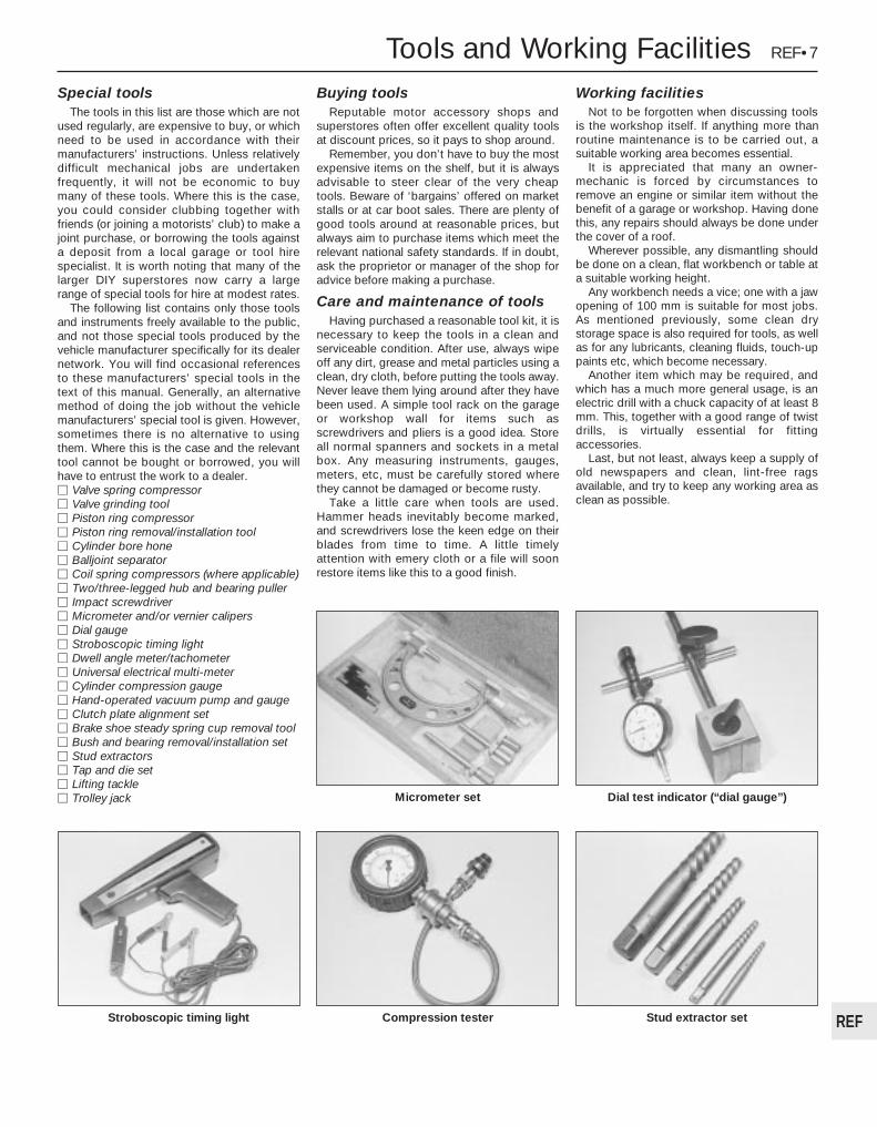
Special toolsThe tools in this list are those which are not
used regularly, are expensive to buy, or whichneed to be used in accordance with theirmanufacturers’ instructions. Unless relativelydifficult mechanical jobs are undertakenfrequently, it will not be economic to buymany of these tools. Where this is the case,you could consider clubbing together withfriends (or joining a motorists’ club) to make ajoint purchase, or borrowing the tools againsta deposit from a local garage or tool hirespecialist. It is worth noting that many of thelarger DIY superstores now carry a largerange of special tools for hire at modest rates.
The following list contains only those toolsand instruments freely available to the public,and not those special tools produced by thevehicle manufacturer specifically for its dealernetwork. You will find occasional referencesto these manufacturers’ special tools in thetext of this manual. Generally, an alternativemethod of doing the job without the vehiclemanufacturers’ special tool is given. However,sometimes there is no alternative to usingthem. Where this is the case and the relevanttool cannot be bought or borrowed, you willhave to entrust the work to a dealer.M Valve spring compressorM Valve grinding toolM Piston ring compressorM Piston ring removal/installation toolM Cylinder bore honeM Balljoint separatorM Coil spring compressors (where applicable)M Two/three-legged hub and bearing pullerM Impact screwdriverM Micrometer and/or vernier calipersM Dial gaugeM Stroboscopic timing lightM Dwell angle meter/tachometerM Universal electrical multi-meterM Cylinder compression gaugeM Hand-operated vacuum pump and gaugeM Clutch plate alignment setM Brake shoe steady spring cup removal toolM Bush and bearing removal/installation setM Stud extractorsM Tap and die setM Lifting tackleM Trolley jack
Buying toolsReputable motor accessory shops and
superstores often offer excellent quality toolsat discount prices, so it pays to shop around.
Remember, you don’t have to buy the mostexpensive items on the shelf, but it is alwaysadvisable to steer clear of the very cheaptools. Beware of ‘bargains’ offered on marketstalls or at car boot sales. There are plenty ofgood tools around at reasonable prices, butalways aim to purchase items which meet therelevant national safety standards. If in doubt,ask the proprietor or manager of the shop foradvice before making a purchase.
Care and maintenance of toolsHaving purchased a reasonable tool kit, it is
necessary to keep the tools in a clean andserviceable condition. After use, always wipeoff any dirt, grease and metal particles using aclean, dry cloth, before putting the tools away.Never leave them lying around after they havebeen used. A simple tool rack on the garageor workshop wall for items such asscrewdrivers and pliers is a good idea. Storeall normal spanners and sockets in a metalbox. Any measuring instruments, gauges,meters, etc, must be carefully stored wherethey cannot be damaged or become rusty.
Take a little care when tools are used.Hammer heads inevitably become marked,and screwdrivers lose the keen edge on theirblades from time to time. A little timelyattention with emery cloth or a file will soonrestore items like this to a good finish.
Working facilitiesNot to be forgotten when discussing tools
is the workshop itself. If anything more thanroutine maintenance is to be carried out, asuitable working area becomes essential.
It is appreciated that many an owner-mechanic is forced by circumstances toremove an engine or similar item without thebenefit of a garage or workshop. Having donethis, any repairs should always be done underthe cover of a roof.
Wherever possible, any dismantling shouldbe done on a clean, flat workbench or table ata suitable working height.
Any workbench needs a vice; one with a jawopening of 100 mm is suitable for most jobs.As mentioned previously, some clean drystorage space is also required for tools, as wellas for any lubricants, cleaning fluids, touch-uppaints etc, which become necessary.
Another item which may be required, andwhich has a much more general usage, is anelectric drill with a chuck capacity of at least 8mm. This, together with a good range of twistdrills, is virtually essential for fittingaccessories.
Last, but not least, always keep a supply ofold newspapers and clean, lint-free ragsavailable, and try to keep any working area asclean as possible.
Tools and Working Facilities REF•7
REFStroboscopic timing light Stud extractor setCompression tester
Dial test indicator (“dial gauge”)Micrometer set

REF•8 MOT Test ChecksThis is a guide to getting your vehicle through the MOT test.
Obviously it will not be possible to examine the vehicle to the samestandard as the professional MOT tester. However, working throughthe following checks will enable you to identify any problem areasbefore submitting the vehicle for the test.
Where a testable component is in borderline condition, the testerhas discretion in deciding whether to pass or fail it. The basis of suchdiscretion is whether the tester would be happy for a close relative orfriend to use the vehicle with the component in that condition. If thevehicle presented is clean and evidently well cared for, the tester maybe more inclined to pass a borderline component than if the vehicle isscruffy and apparently neglected.
It has only been possible to summarise the test requirements here,based on the regulations in force at the time of printing. Test standardsare becoming increasingly stringent, although there are someexemptions for older vehicles. For full details obtain a copy of the Haynespublication Pass the MOT! (available from stockists of Haynes manuals).
An assistant will be needed to help carry out some of these checks.
The checks have been sub-divided into four categories, as follows:
HandbrakeM Test the operation of the handbrake.Excessive travel (too many clicks) indicatesincorrect brake or cable adjustment.M Check that the handbrake cannot bereleased by tapping the lever sideways. Checkthe security of the lever mountings.
FootbrakeM Depress the brake pedal and check that itdoes not creep down to the floor, indicating amaster cylinder fault. Release the pedal, waita few seconds, then depress it again. If thepedal travels nearly to the floor before firmresistance is felt, brake adjustment or repair isnecessary. If the pedal feels spongy, there isair in the hydraulic system which must beremoved by bleeding.
M Check that the brake pedal is secure and ingood condition. Check also for signs of fluidleaks on the pedal, floor or carpets, whichwould indicate failed seals in the brake mastercylinder.M Check the servo unit (when applicable) byoperating the brake pedal several times, thenkeeping the pedal depressed and starting theengine. As the engine starts, the pedal willmove down slightly. If not, the vacuum hose orthe servo itself may be faulty.
Steering wheel and column M Examine the steering wheel for fractures orlooseness of the hub, spokes or rim. M Move the steering wheel from side to sideand then up and down. Check that the steering wheel is not loose on the column,indicating wear or a loose retaining nut.Continue moving the steering wheel as before,but also turn it slightly from left to right. M Check that the steering wheel is not looseon the column, and that there is no abnormal
movement of the steering wheel, indicatingwear in the column support bearings orcouplings.
Windscreen and mirrors M The windscreen must be free of cracks orother significant damage within the driver’sfield of view. (Small stone chips areacceptable.) Rear view mirrors must besecure, intact, and capable of being adjusted.
1Checks carried outFROM THE DRIVER’S SEAT
1Checks carried outFROM THE DRIVER’SSEAT
2Checks carried outWITH THE VEHICLEON THE GROUND
3Checks carried outWITH THE VEHICLERAISED AND THEWHEELS FREE TOTURN
4Checks carried out onYOUR VEHICLE’SEXHAUST EMISSIONSYSTEM

MOT Test Checks REF•9
REF
Seat belts and seats Note: The following checks are applicable toall seat belts, front and rear.
M Examine the webbing of all the belts(including rear belts if fitted) for cuts, seriousfraying or deterioration. Fasten and unfasteneach belt to check the buckles. If applicable,check the retracting mechanism. Check thesecurity of all seat belt mountings accessiblefrom inside the vehicle.M The front seats themselves must besecurely attached and the backrests mustlock in the upright position.
Doors M Both front doors must be able to be openedand closed from outside and inside, and mustlatch securely when closed.
Vehicle identificationM Number plates must be in good condition,secure and legible, with letters and numberscorrectly spaced – spacing at (A) should betwice that at (B).
M The VIN plate (A) and homologation plate(B) must be legible.
Electrical equipmentM Switch on the ignition and check the operation of the horn.M Check the windscreen washers and wipers,examining the wiper blades; renew damagedor perished blades. Also check the operationof the stop-lights.
M Check the operation of the sidelights andnumber plate lights. The lenses and reflectorsmust be secure, clean and undamaged. M Check the operation and alignment of theheadlights. The headlight reflectors must notbe tarnished and the lenses must beundamaged.M Switch on the ignition and check the operation of the direction indicators (includingthe instrument panel tell-tale) and the hazardwarning lights. Operation of the sidelights andstop-lights must not affect the indicators - if itdoes, the cause is usually a bad earth at therear light cluster.M Check the operation of the rear foglight(s),including the warning light on the instrumentpanel or in the switch.
FootbrakeM Examine the master cylinder, brake pipesand servo unit for leaks, loose mountings, corrosion or other damage.
M The fluid reservoir must be secure and thefluid level must be between the upper (A) andlower (B) markings.
M Inspect both front brake flexible hoses forcracks or deterioration of the rubber. Turn thesteering from lock to lock, and ensure that thehoses do not contact the wheel, tyre, or anypart of the steering or suspension mechanism.With the brake pedal firmly depressed, checkthe hoses for bulges or leaks under pressure.
Steering and suspensionM Have your assistant turn the steering wheelfrom side to side slightly, up to the point wherethe steering gear just begins to transmit thismovement to the roadwheels. Check forexcessive free play between the steeringwheel and the steering gear, indicating wear orinsecurity of the steering column joints, thecolumn-to-steering gear coupling, or thesteering gear itself.M Have your assistant turn the steering wheelmore vigorously in each direction, so that theroadwheels just begin to turn. As this is done,examine all the steering joints, linkages,fittings and attachments. Renew anycomponent that shows signs of wear or damage. On vehicles with power steering,check the security and condition of the steering pump, drivebelt and hoses.M Check that the vehicle is standing level,and at approximately the correct ride height.
Shock absorbersM Depress each corner of the vehicle in turn,then release it. The vehicle should rise andthen settle in its normal position. If the vehiclecontinues to rise and fall, the shock absorberis defective. A shock absorber which hasseized will also cause the vehicle to fail.
2Checks carried outWITH THE VEHICLE ON THEGROUND

REF•10 MOT Test Checks
Exhaust systemM Start the engine. With your assistant holding a rag over the tailpipe, check theentire system for leaks. Repair or renewleaking sections.
Jack up the front and rear of the vehicle,and securely support it on axle stands.Position the stands clear of the suspensionassemblies. Ensure that the wheels areclear of the ground and that the steeringcan be turned from lock to lock.
Steering mechanism M Have your assistant turn the steering fromlock to lock. Check that the steering turnssmoothly, and that no part of the steeringmechanism, including a wheel or tyre, foulsany brake hose or pipe or any part of the bodystructure.M Examine the steering rack rubber gaitersfor damage or insecurity of the retaining clips.If power steering is fitted, check for signs ofdamage or leakage of the fluid hoses, pipes orconnections. Also check for excessivestiffness or binding of the steering, a missingsplit pin or locking device, or severe corrosionof the body structure within 30 cm of anysteering component attachment point.
Front and rear suspension andwheel bearings M Starting at the front right-hand side, graspthe roadwheel at the 3 o’clock and 9 o’clockpositions and shake it vigorously. Check forfree play or insecurity at the wheel bearings,suspension balljoints, or suspension mount-ings, pivots and attachments.M Now grasp the wheel at the 12 o’clock and6 o’clock positions and repeat the previousinspection. Spin the wheel, and check forroughness or tightness of the front wheelbearing.
M If excess free play is suspected at acomponent pivot point, this can be confirmedby using a large screwdriver or similar tool andlevering between the mounting and thecomponent attachment. This will confirmwhether the wear is in the pivot bush, itsretaining bolt, or in the mounting itself (the boltholes can often become elongated).
M Carry out all the above checks at the otherfront wheel, and then at both rear wheels.
Springs and shock absorbers M Examine the suspension struts (whenapplicable) for serious fluid leakage, corrosion,or damage to the casing. Also check thesecurity of the mounting points.M If coil springs are fitted, check that thespring ends locate in their seats, and that thespring is not corroded, cracked or broken.M If leaf springs are fitted, check that allleaves are intact, that the axle is securelyattached to each spring, and that there is nodeterioration of the spring eye mountings,bushes, and shackles.
M The same general checks apply to vehiclesfitted with other suspension types, such astorsion bars, hydraulic displacer units, etc.Ensure that all mountings and attachments aresecure, that there are no signs of excessivewear, corrosion or damage, and (on hydraulictypes) that there are no fluid leaks or damagedpipes.M Inspect the shock absorbers for signs ofserious fluid leakage. Check for wear of themounting bushes or attachments, or damageto the body of the unit.
Driveshafts(fwd vehicles only)M Rotate each front wheel in turn and inspectthe constant velocity joint gaiters for splits ordamage. Also check that each driveshaft isstraight and undamaged.
Braking system M If possible without dismantling, checkbrake pad wear and disc condition. Ensurethat the friction lining material has not wornexcessively, (A) and that the discs are notfractured, pitted, scored or badly worn (B).
M Examine all the rigid brake pipesunderneath the vehicle, and the flexiblehose(s) at the rear. Look for corrosion, chafingor insecurity of the pipes, and for signs ofbulging under pressure, chafing, splits ordeterioration of the flexible hoses.M Look for signs of fluid leaks at the brakecalipers or on the brake backplates. Repair orrenew leaking components.M Slowly spin each wheel, while yourassistant depresses and releases thefootbrake. Ensure that each brake is operatingand does not bind when the pedal is released.
3Checks carried outWITH THE VEHICLE RAISEDAND THE WHEELS FREE TOTURN

MOT Test Checks REF•11
REF
M Examine the handbrake mechanism,checking for frayed or broken cables,excessive corrosion, or wear or insecurity ofthe linkage. Check that the mechanism workson each relevant wheel, and releases fully,without binding.M It is not possible to test brake efficiencywithout special equipment, but a road testcan be carried out later to check that thevehicle pulls up in a straight line.
Fuel and exhaust systemsM Inspect the fuel tank (including the fillercap), fuel pipes, hoses and unions. Allcomponents must be secure and free fromleaks.M Examine the exhaust system over its entirelength, checking for any damaged, broken ormissing mountings, security of the retainingclamps and rust or corrosion.
Wheels and tyres M Examine the sidewalls and tread area ofeach tyre in turn. Check for cuts, tears, lumps,bulges, separation of the tread, and exposureof the ply or cord due to wear or damage.Check that the tyre bead is correctly seatedon the wheel rim, that the valve is sound and
properly seated, and that the wheel is notdistorted or damaged. M Check that the tyres are of the correct sizefor the vehicle, that they are of the same sizeand type on each axle, and that the pressuresare correct.M Check the tyre tread depth. The legalminimum at the time of writing is 1.6 mm overat least three-quarters of the tread width.Abnormal tread wear may indicate incorrectfront wheel alignment.
Body corrosionM Check the condition of the entire vehiclestructure for signs of corrosion in load-bearing areas. (These include chassis boxsections, side sills, cross-members, pillars,and all suspension, steering, braking systemand seat belt mountings and anchorages.)Any corrosion which has seriously reducedthe thickness of a load-bearing area is likely tocause the vehicle to fail. In this caseprofessional repairs are likely to be needed.M Damage or corrosion which causes sharpor otherwise dangerous edges to be exposedwill also cause the vehicle to fail.
Petrol modelsM Have the engine at normal operatingtemperature, and make sure that it is in goodtune (ignition system in good order, air filterelement clean, etc).M Before any measurements are carried out,raise the engine speed to around 2500 rpm,and hold it at this speed for 20 seconds. Allowthe engine speed to return to idle, and watch
for smoke emissions from the exhausttailpipe. If the idle speed is obviously muchtoo high, or if dense blue or clearly-visibleblack smoke comes from the tailpipe for morethan 5 seconds, the vehicle will fail. As a ruleof thumb, blue smoke signifies oil being burnt(engine wear) while black smoke signifiesunburnt fuel (dirty air cleaner element, or othercarburettor or fuel system fault).M An exhaust gas analyser capable ofmeasuring carbon monoxide (CO) andhydrocarbons (HC) is now needed. If such aninstrument cannot be hired or borrowed, alocal garage may agree to perform the checkfor a small fee.
CO emissions (mixture)M At the time of writing, the maximum COlevel at idle is 3.5% for vehicles first used afterAugust 1986 and 4.5% for older vehicles.From January 1996 a much tighter limit(around 0.5%) applies to catalyst-equippedvehicles first used from August 1992. If theCO level cannot be reduced far enough topass the test (and the fuel and ignitionsystems are otherwise in good condition) thenthe carburettor is badly worn, or there is someproblem in the fuel injection system orcatalytic converter (as applicable).
HC emissionsM With the CO emissions within limits, HCemissions must be no more than 1200 ppm(parts per million). If the vehicle fails this testat idle, it can be re-tested at around 2000rpm; if the HC level is then 1200 ppm or less,this counts as a pass.M Excessive HC emissions can be caused byoil being burnt, but they are more likely to bedue to unburnt fuel.
Diesel modelsM The only emission test applicable to Dieselengines is the measuring of exhaust smokedensity. The test involves accelerating theengine several times to its maximumunloaded speed.
Note: It is of the utmost importance that theengine timing belt is in good condition beforethe test is carried out.
M Excessive smoke can be caused by a dirtyair cleaner element. Otherwise, professionaladvice may be needed to find the cause.
4Checks carried out onYOUR VEHICLE’S EXHAUSTEMISSION SYSTEM

Engine . . . . . . . . . . . . . . . . . . . . . . . . . . . . . .1mm Engine fails to rotate when attempting to startmm Engine rotates, but will not startmm Engine difficult to start when coldmm Engine difficult to start when hotmm Starter motor noisy or excessively-rough in engagementmm Engine starts, but stops immediatelymm Engine idles erraticallymm Engine misfires at idle speedmm Engine misfires throughout the driving speed rangemm Engine hesitates on accelerationmm Engine stallsmm Engine lacks powermm Engine backfiresmm Oil pressure warning light illuminated with engine runningmm Engine runs-on after switching offmm Engine noises
Cooling system . . . . . . . . . . . . . . . . . . . . . .2mm Overheatingmm Overcoolingmm External coolant leakagemm Internal coolant leakagemm Corrosion
Fuel and exhaust systems . . . . . . . . . . . . .3mm Excessive fuel consumptionmm Fuel leakage and/or fuel odourmm Excessive noise or fumes from exhaust system
Clutch . . . . . . . . . . . . . . . . . . . . . . . . . . . . . .4mm Pedal travels to floor - no pressure or very little resistancemm Clutch fails to disengage (unable to select gears)mm Clutch slips (engine speed increases, with no increase in vehicle
speed)mm Judder as clutch is engagedmm Noise when depressing or releasing clutch pedal
Manual transmission . . . . . . . . . . . . . . . . . .5mm Noisy in neutral with engine runningmm Noisy in one particular gearmm Difficulty engaging gearsmm Jumps out of gearmm Vibrationmm Lubricant leaks
Automatic transmission . . . . . . . . . . . . . . .6mm Fluid leakagemm Transmission fluid brown, or has burned smellmm General gear selection problemsmm Transmission will not downshift (kickdown) with accelerator fully
depressedmm Engine will not start in any gear, or starts in gears other than
Park or Neutralmm Transmission slips, shifts roughly, is noisy, or has no drive in
forward or reverse gears
Driveshafts . . . . . . . . . . . . . . . . . . . . . . . . . .7mm Clicking or knocking noise on turns (at slow speed on full-lock)mm Vibration when accelerating or decelerating
Braking system . . . . . . . . . . . . . . . . . . . . . .8mm Vehicle pulls to one side under brakingmm Noise (grinding or high-pitched squeal) when brakes appliedmm Excessive brake pedal travelmm Brake pedal feels spongy when depressedmm Excessive brake pedal effort required to stop vehiclemm Judder felt through brake pedal or steering wheel when brakingmm Brakes bindingmm Rear wheels locking under normal braking
Suspension and steering systems . . . . . . .9mm Vehicle pulls to one sidemm Wheel wobble and vibrationmm Excessive pitching and/or rolling around corners, or during
brakingmm Wandering or general instabilitymm Excessively-stiff steeringmm Excessive play in steeringmm Lack of power assistancemm Tyre wear excessive
Electrical system . . . . . . . . . . . . . . . . . . . .10mm Battery will not hold a charge for more than a few daysmm Ignition/no-charge warning light remains illuminated with engine
runningmm Ignition/no-charge warning light fails to come onmm Lights inoperativemm Instrument readings inaccurate or erraticmm Horn inoperative, or unsatisfactory in operationmm Windscreen/tailgate wipers inoperative, or unsatisfactory in
operationmm Windscreen/tailgate washers inoperative, or unsatisfactory in
operationmm Electric windows inoperative, or unsatisfactory in operationmm Central locking system inoperative, or unsatisfactory in operation
REF•12 Fault Finding
IntroductionThe vehicle owner who does his or her own maintenance according
to the recommended service schedules should not have to use thissection of the manual very often. Modern component reliability is suchthat, provided those items subject to wear or deterioration areinspected or renewed at the specified intervals, sudden failure iscomparatively rare. Faults do not usually just happen as a result ofsudden failure, but develop over a period of time. Major mechanicalfailures in particular are usually preceded by characteristic symptomsover hundreds or even thousands of miles. Those components whichdo occasionally fail without warning are often small and easily carriedin the vehicle.
With any fault-finding, the first step is to decide where to begininvestigations. Sometimes this is obvious, but on other occasions, alittle detective work will be necessary. The owner who makes half adozen haphazard adjustments or replacements may be successful incuring a fault (or its symptoms), but will be none the wiser if the faultrecurs, and ultimately may have spent more time and money than wasnecessary. A calm and logical approach will be found to be moresatisfactory in the long run. Always take into account any warningsigns or abnormalities that may have been noticed in the periodpreceding the fault - power loss, high or low gauge readings, unusualsmells, etc - and remember that failure of components such as fuses orspark plugs may only be pointers to some underlying fault.

The pages which follow provide an easy-reference guide to themore common problems which may occur during the operation of thevehicle. These problems and their possible causes are groupedunder headings denoting various components or systems, such asEngine, Cooling system, etc. The Chapter and/or Section which dealswith the problem is also shown in brackets. Whatever the fault,certain basic principles apply. These are as follows:
Verify the fault. This is simply a matter of being sure that you knowwhat the symptoms are before starting work. This is particularlyimportant if you are investigating a fault for someone else, who maynot have described it very accurately.
Don’t overlook the obvious. For example, if the vehicle won’t start, isthere fuel in the tank? (Don’t take anyone else’s word on this particularpoint, and don’t trust the fuel gauge either!) If an electrical fault is
indicated, look for loose or broken wires before digging out the test gear.Cure the disease, not the symptom. Substituting a flat battery with
a fully-charged one will get you off the hard shoulder, but if theunderlying cause is not attended to, the new battery will go the sameway. Similarly, changing oil-fouled spark plugs for a new set will getyou moving again, but remember that the reason for the fouling (if itwasn’t simply an incorrect grade of plug) will have to be establishedand corrected.
Don’t take anything for granted. Particularly, don’t forget that a“new” component may itself be defective (especially if it’s beenrattling around in the boot for months), and don’t leave componentsout of a fault diagnosis sequence just because they are new orrecently-fitted. When you do finally diagnose a difficult fault, you’llprobably realise that all the evidence was there from the start.
Fault Finding REF•13
REF
1 EngineEngine fails to rotate when attempting to startmm Battery terminal connections loose or corroded
(“Weekly checks”).mm Battery discharged or faulty (Chapter 5A).mm Broken, loose or disconnected wiring in the starting circuit
(Chapter 5A).mm Defective starter solenoid or switch (Chapter 5A).mm Defective starter motor (Chapter 5A).mm Starter pinion or flywheel/driveplate ring gear teeth loose or
broken (Chapter 2A, 2B or 5A).mm Engine earth strap broken or disconnected (Chapter 5A).
Engine rotates, but will not startmm Fuel tank empty.mm Battery discharged (engine rotates slowly) (Chapter 5A).mm Battery terminal connections loose or corroded
(“Weekly checks”).mm Ignition components damp or damaged (Chapter 1 and 5B).mm Broken, loose or disconnected wiring in the ignition circuit
(Chapters 1 and 5B).mm Worn, faulty or incorrectly-gapped spark plugs (Chapter 1).mm Faulty choke or carburettor (Chapter 4A).mm Fuel injection system fault (Chapter 4B or 4C).mm Major mechanical failure (eg broken timing chain)
(Chapter 2A, 2B or 2C).
Engine difficult to start when coldmm Battery discharged (Chapter 5A).mm Battery terminal connections loose or corroded
(“Weekly checks”).mm Worn, faulty or incorrectly-gapped spark plugs (Chapter 1).mm Faulty choke or carburettor (Chapter 4A).mm Fuel injection system fault (Chapter 4B or 4C).mm Other ignition system fault (Chapters 1 and 5B).mm Low cylinder compressions (Chapter 2A, 2B or 2C).
Engine difficult to start when hotmm Air filter element dirty or clogged (Chapter 1).mm Faulty choke or carburettor (Chapter 4A).mm Fuel injection system fault (Chapter 4B or 4C).mm Low cylinder compressions (Chapter 2A or 2B).
Starter motor noisy or excessively-rough in engagementmm Starter pinion or flywheel/driveplate ring gear teeth loose or
broken (Chapter 2A, 2B or 5A).mm Starter motor mounting bolts loose or missing (Chapter 5A).mm Starter motor internal components worn or damaged
(Chapter 5A).
Engine starts, but stops immediatelymm Loose or faulty electrical connections in the ignition circuit
(Chapters 1 and 5B).mm Vacuum leak at the carburettor, throttle body or inlet manifold
(Chapters 4A, 4B, 4C or 4D).mm Faulty carburettor (Chapter 4A).mm Fuel injection system fault (Chapter 4B or 4C).
Engine idles erraticallymm Incorrectly-adjusted idle speed (Chapter 4A, 4B or 4C).mm Air filter element clogged (Chapter 1).mm Vacuum leak at the carburettor, throttle body, inlet manifold or
associated hoses (Chapter 4A, 4B, 4C or 4D).mm Worn, faulty or incorrectly-gapped spark plugs (Chapter 1).mm Uneven or low cylinder compressions (Chapter 2A or 2B).mm Camshaft lobes worn (Chapter 2A or 2B).mm Timing belt incorrectly tensioned (Chapter 2A or 2B).mm Faulty carburettor (Chapter 4A).mm Fuel injection system fault (Chapter 4B or 4C).
Engine misfires at idle speedmm Worn, faulty or incorrectly-gapped spark plugs (Chapter 1).mm Faulty spark plug HT leads (Chapter 1).mm Vacuum leak at the carburettor, throttle body, inlet manifold or
associated hoses (Chapter 4A, 4B, 4C or 4D).mm Faulty carburettor (Chapter 4A).mm Fuel injection system fault (Chapter 4B or 4C).mm Distributor cap cracked or tracking internally (Chapter 1).mm Uneven or low cylinder compressions (Chapter 2A or 2B).mm Disconnected, leaking, or perished crankcase ventilation hoses
(Chapter 4D).
Engine misfires throughout the driving speed rangemm Fuel filter choked (Chapter 1).mm Fuel pump faulty, or delivery pressure low
(Chapter 4A, 4B or 4C).mm Fuel tank vent blocked, or fuel pipes restricted
(Chapter 4A, 4B or 4C).mm Vacuum leak at the carburettor, throttle body, inlet manifold or
associated hoses (Chapter 4A, 4B, 4C or 4D).mm Worn, faulty or incorrectly-gapped spark plugs (Chapter 1).mm Faulty spark plug HT leads (Chapter 1).mm Distributor cap cracked or tracking internally (Chapter 1).mm Faulty ignition coil (Chapter 5B).mm Uneven or low cylinder compressions (Chapter 2A or 2B).mm Faulty carburettor (Chapter 4A).mm Fuel injection system fault (Chapter 4B or 4C).

Engine hesitates on accelerationmm Worn, faulty or incorrectly-gapped spark plugs (Chapter 1).mm Vacuum leak at the carburettor, throttle body, inlet manifold or
associated hoses (Chapter 4A, 4B or 4C).mm Faulty carburettor (Chapter 4A).mm Fuel injection system fault (Chapter 4B or 4C).
Engine stallsmm Vacuum leak at the carburettor, throttle body, inlet manifold or
associated hoses (Chapter 4A, 4B or 4C).mm Fuel filter choked (Chapter 1).mm Fuel pump faulty, or delivery pressure low
(Chapter 4A, 4B or 4C).mm Fuel tank vent blocked, or fuel pipes restricted
(Chapter 4A, 4B or 4C).mm Faulty carburettor (Chapter 4A).mm Fuel injection system fault (Chapter 4B or 4C).
Engine lacks powermm Timing belt incorrectly fitted or tensioned (Chapter 2A or 2B).mm Fuel filter choked (Chapter 1).mm Fuel pump faulty, or delivery pressure low
(Chapter 4A, 4B or 4C).mm Uneven or low cylinder compressions (Chapter 2A or 2B).mm Worn, faulty or incorrectly-gapped spark plugs (Chapter 1).mm Vacuum leak at the carburettor, throttle body, inlet manifold or
associated hoses (Chapter 4A, 4B or 4C).mm Faulty carburettor (Chapter 4A).mm Fuel injection system fault (Chapter 4B or 4C).mm Brakes binding (Chapters 1 and 9).mm Clutch slipping (Chapter 6).
Engine backfiresmm Timing belt incorrectly fitted or tensioned (Chapter 2A).mm Vacuum leak at the carburettor, throttle body, inlet manifold or
associated hoses (Chapter 4A, 4B or 4C).mm Faulty carburettor (Chapter 4A).mm Fuel injection system fault (Chapter 4B or 4C).
Oil pressure warning light illuminated withengine runningmm Low oil level, or incorrect oil grade (Chapter 1).mm Faulty oil pressure sensor (Chapter 2A or 2B).mm Worn engine bearings and/or oil pump (Chapter 2A, 2B or 2C).mm Excessively high engine operating temperature (Chapter 3).mm Oil pressure relief valve defective (Chapter 2A or 2B).mm Oil pick-up strainer clogged (Chapter 2C).Note: Low oil pressure in a high-mileage engine at tickover is notnecessarily a cause for concern. Sudden pressure loss at speed is farmore significant. In any event, check the gauge or warning lightsender before condemning the engine.
Engine runs-on after switching offmm Excessive carbon build-up in engine (Chapter 2A, 2B or 2C).mm Excessively high engine operating temperature (Chapter 3).
Engine noises
Pre-ignition (pinking) or knocking during acceleration or under loadmm Ignition timing incorrect/ignition system fault (Chapters 1 and 5B).mm Incorrect grade of spark plug (Chapter 1).mm Incorrect grade of fuel (Chapter 1).mm Vacuum leak at carburettor, throttle body, inlet manifold or
associated hoses (Chapter 4A, 4B or 4C).mm Excessive carbon build-up in engine (Chapter 2A, 2B or 2C).mm Faulty carburettor (Chapter 4A).mm Fuel injection system fault (Chapter 4B or 4C).
Whistling or wheezing noisesmm Leaking inlet manifold or throttle body gasket
(Chapter 4A, 4B or 4C).mm Leaking exhaust manifold gasket (Chapter 4A, 4B or 4C).mm Leaking vacuum hose (Chapters 4A, 4B, and 4C).mm Blowing cylinder head gasket (Chapter 2A or 2B).
Tapping or rattling noisesmm Worn valve gear or camshaft (Chapter 2A or 2B).mm Incorrect valve clearances (Chapter 1)mm Ancillary component fault (water pump, alternator, etc)
(Chapters 3, 5A, etc).
Knocking or thumping noisesmm Worn big-end bearings (regular heavy knocking, perhaps less
under load) (Chapter 2C).mm Worn main bearings (rumbling and knocking, perhaps worsening
under load) (Chapter 2C).mm Piston slap (most noticeable when cold) (Chapter 2C).mm Ancillary component fault (water pump, alternator, etc)
(Chapters 3, 5A, etc).
REF•14 Fault Finding
1 Engine (continued)

2 Cooling system
Fault Finding REF•15
REF
Overheatingmm Insufficient coolant in system (“Weekly checks”).mm Thermostat faulty (Chapter 3).mm Radiator core blocked, or grille restricted (Chapter 3).mm Electric cooling fan or thermostatic switch faulty (Chapter 3).mm Pressure cap faulty (Chapter 3).mm Ignition timing incorrect, or ignition system fault
(Chapters 1 and 5B).mm Inaccurate temperature gauge sender unit (Chapter 3).mm Airlock in cooling system (Chapter 1).
Overcoolingmm Thermostat faulty (Chapter 3).mm Inaccurate temperature gauge sender unit (Chapter 3).
External coolant leakagemm Deteriorated or damaged hoses or hose clips (Chapter 1).mm Radiator core or heater matrix leaking (Chapter 3).mm Pressure cap faulty (Chapter 3).mm Water pump internal seal leaking (Chapter 3).mm Water pump gasket leaking (Chapter 3).mm Boiling due to overheating (Chapter 3).mm Core plug leaking (Chapter 2C).
Internal coolant leakagemm Leaking cylinder head gasket (Chapter 2A or 2B).mm Cracked cylinder head or cylinder block (Chapter 2A, 2B or 2C).
Corrosionmm Infrequent draining and flushing (Chapter 1).mm Incorrect coolant mixture or inappropriate coolant type (Chapter 1).
3 Fuel and exhaust systemsExcessive fuel consumptionmm Air filter element dirty or clogged (Chapter 1).mm Faulty carburettor (Chapter 4A).mm Fuel injection system fault (Chapter 4B or 4C).mm Ignition timing incorrect or ignition system fault
(Chapters 1 and 5B).mm Tyres under-inflated (“Weekly checks”).
Fuel leakage and/or fuel odourmm Damaged fuel tank, pipes or connections
(Chapters 1 and 4A, 4B or 4C).
Excessive noise or fumes from exhaust systemmm Leaking exhaust system or manifold joints (Chapters 1 and 4D).mm Leaking, corroded or damaged silencers or pipe
(Chapters 1 and 4D).mm Broken mountings causing body or suspension contact
(Chapter 4D).
4 ClutchPedal travels to floor - no pressure or very little resistancemm Broken clutch cable (Chapter 6).mm Incorrect clutch cable adjustment (Chapter 6).mm Broken clutch release bearing or arm (Chapter 6).mm Broken diaphragm spring in clutch pressure plate (Chapter 6).
Clutch fails to disengage (unable to select gears)mm Incorrect clutch cable adjustment (Chapter 6).mm Clutch disc sticking on splines (Chapter 6).mm Clutch disc sticking to flywheel or pressure plate (Chapter 6).mm Faulty pressure plate assembly (Chapter 6).mm Clutch release mechanism worn or incorrectly assembled
(Chapter 6).
Clutch slips (engine speed increases, with no increase in vehicle speed)mm Incorrect clutch cable adjustment (Chapter 6).mm Clutch disc linings excessively worn (Chapter 6).mm Clutch disc linings contaminated with oil or grease (Chapter 6).mm Faulty pressure plate or weak diaphragm spring (Chapter 6).
Judder as clutch is engagedmm Clutch disc linings contaminated with oil or grease (Chapter 6).mm Clutch disc linings excessively worn (Chapter 6).mm Clutch cable sticking or frayed (Chapter 6).mm Faulty or distorted pressure plate or diaphragm spring (Chapter 6).mm Worn or loose engine or gearbox mountings (Chapter 2A or 2B).mm Clutch disc hub or shaft splines worn (Chapter 6).
Noise when depressing or releasing clutch pedalmm Worn clutch release bearing (Chapter 6).mm Worn or dry clutch pedal bushes (Chapter 6).mm Faulty pressure plate assembly (Chapter 6).mm Pressure plate diaphragm spring broken (Chapter 6).mm Broken clutch disc cushioning springs (Chapter 6).

7 Driveshafts
5 Manual transmission
REF•16 Fault Finding
Noisy in neutral with engine runningmm Primary gears and bearings worn (noise apparent with clutch
pedal released, but not when depressed) (Chapter 7A).*mm Clutch release bearing worn (noise apparent with clutch pedal
depressed, possibly less when released) (Chapter 6).
Noisy in one particular gearmm Worn, damaged or chipped gear teeth (Chapter 7A).*
Difficulty engaging gearsmm Clutch fault (Chapter 6).mm Worn or damaged gear linkage (Chapter 7A).mm Incorrectly-adjusted gear linkage (Chapter 7A).mm Worn synchroniser units (Chapter 7A).*
Jumps out of gearmm Worn or damaged gear linkage (Chapter 7A).mm Incorrectly-adjusted gear linkage (Chapter 7A).mm Worn synchroniser units (Chapter 7A).*mm Worn selector forks (Chapter 7A).*
Vibrationmm Lack of oil (Chapter 1).mm Worn bearings (Chapter 7A).*
Lubricant leaksmm Leaking differential output oil seal (Chapter 7A).mm Leaking housing joint (Chapter 7A).*mm Leaking input shaft oil seal (Chapter 7A).**Although the corrective action necessary to remedy the symptomsdescribed is beyond the scope of the home mechanic, the aboveinformation should be helpful in isolating the cause of the condition,so that the owner can communicate clearly with a professionalmechanic.
6 Automatic transmissionNote: Due to the complexity of the automatic transmission, it isdifficult for the home mechanic to properly diagnose and service thisunit. For problems other than the following, the vehicle should betaken to a dealer service department or automatic transmissionspecialist.
Fluid leakagemm Automatic transmission fluid is usually deep red in colour. Fluid
leaks should not be confused with engine oil, which can easilybe blown onto the transmission by air flow.
mm To determine the source of a leak, first remove all built-up dirtand grime from the transmission housing and surrounding areas,using a degreasing agent or by steam-cleaning. Drive the vehicleat low speed, so that air flow will not blow the leak far from itssource. Raise and support the vehicle, and determine where theleak is coming from. The following are common areas of leakage.
a) Fluid pan (Chapter 1 and 7B).b) Dipstick tube (Chapter 1 and 7B).c) Transmission-to-fluid cooler fluid pipes/unions (Chapter 7B).
Transmission fluid brown, or has burned smellmm Transmission fluid level low, or fluid in need of renewal
(Chapter 1).
General gear selection problemsmm Chapter 7B deals with checking and adjusting the selector cable
on automatic transmissions. The following are commonproblems which may be caused by a poorly-adjusted cable:
a) Engine starting in gears other than Park or Neutral.b) Indicator on gear selector lever pointing to a gear other than the
one actually being used.c) Vehicle moves when in Park or Neutral.d) Poor gear shift quality, or erratic gear changes.
mm Refer to Chapter 7B for the selector cable adjustment procedure.
Transmission will not downshift (kickdown) with accelerator pedal fully depressedmm Low transmission fluid level (Chapter 1).mm Incorrect selector cable adjustment (Chapter 7B).
Engine will not start in any gear, or starts in gears other than Park or Neutralmm Incorrect starter/inhibitor switch adjustment - where applicable
(Chapter 7B).mm Incorrect selector cable adjustment (Chapter 7B).
Transmission slips, shifts roughly, is noisy, or has no drive in forward or reverse gearsmm There are many probable causes for the above problems, but the
home mechanic should be concerned with only one possibility -fluid level. Before taking the vehicle to a dealer or transmissionspecialist, check the fluid level and condition of the fluid asdescribed in Chapter 1. Correct the fluid level as necessary, orchange the fluid and filter if needed. If the problem persists,professional help will be necessary.
Clicking or knocking noise on turns (at slow speed on full-lock)mm Lack of constant velocity joint lubricant, possibly due to
damaged gaiter (Chapter 8).mm Worn outer constant velocity joint (Chapter 8).
Vibration when accelerating or deceleratingmm Worn inner constant velocity joint (Chapter 8).mm Bent or distorted driveshaft (Chapter 8).

Fault Finding REF•17
REF
8 Braking systemNote: Before assuming that a brake problem exists, make sure thatthe tyres are in good condition and correctly inflated, that the frontwheel alignment is correct, and that the vehicle is not loaded withweight in an unequal manner.
Vehicle pulls to one side under brakingmm Worn, defective, damaged or contaminated front or rear brake
pads/shoes on one side (Chapters 1 and 9).mm Seized or partially-seized brake caliper/wheel cylinder piston
(Chapter 9).mm A mixture of brake pad/shoe lining materials fitted between sides
(Chapter 9).mm Brake caliper mounting bolts loose (Chapter 9).mm Worn or damaged steering or suspension components
(Chapters 1 and 10).
Noise (grinding or high-pitched squeal) when brakes appliedmm Brake pad/shoe friction lining material worn down to metal
backing (Chapters 1 and 9).mm Excessive corrosion of brake disc/drum - may be apparent after
the vehicle has been standing for some time (Chapters 1 and 9).
Excessive brake pedal travelmm Faulty master cylinder (Chapter 9).mm Air in hydraulic system (Chapter 9).mm Faulty vacuum servo unit (Chapter 9).
Brake pedal feels spongy when depressedmm Air in hydraulic system (Chapter 9).mm Deteriorated flexible rubber brake hoses (Chapters 1 and 9).mm Master cylinder mountings loose (Chapter 9).mm Faulty master cylinder (Chapter 9).
Excessive brake pedal effort required to stop vehiclemm Faulty vacuum servo unit (Chapter 9).mm Disconnected, damaged or insecure brake servo vacuum hose
(Chapters 1 and 9).mm Primary or secondary hydraulic circuit failure (Chapter 9).mm Seized brake caliper/wheel cylinder piston(s) (Chapter 9).mm Brake pads/shoes incorrectly fitted (Chapter 9).mm Incorrect grade of brake pads/shoes fitted (Chapter 9).mm Brake pads/shoes contaminated (Chapter 9).
Judder felt through brake pedal or steering wheel when brakingmm Excessive run-out or distortion of brake disc/drum (Chapter 9).mm Brake pad/shoe linings worn (Chapters 1 and 9).mm Brake caliper mounting bolts loose (Chapter 9).mm Wear in suspension or steering components or mountings
(Chapters 1 and 10).
Brakes bindingmm Seized brake caliper/wheel cylinder piston(s) (Chapter 9).mm Incorrectly-adjusted handbrake mechanism (Chapter 9).mm Faulty master cylinder (Chapter 9).
Rear wheels locking under normal brakingmm Seized brake caliper/wheel cylinder piston(s) (Chapter 9).mm Faulty brake pressure regulator (Chapter 9).
9 Suspension and steeringNote: Before diagnosing suspension or steering faults, be sure thatthe trouble is not due to incorrect tyre pressures, mixtures of tyretypes, or binding brakes.
Vehicle pulls to one sidemm Defective tyre (Chapter 1).mm Excessive wear in suspension or steering components
(Chapters 1 and 10).mm Incorrect front wheel alignment (Chapter 10).mm Accident damage to steering or suspension components
(Chapters 1 and 10).
Wheel wobble and vibrationmm Front roadwheels out of balance (vibration felt mainly through
the steering wheel) (Chapter 10).mm Rear roadwheels out of balance (vibration felt throughout the
vehicle) (Chapter 10).mm Roadwheels damaged or distorted (Chapter 10).mm Faulty or damaged tyre (Chapter 1).mm Worn steering or suspension joints, bushes or components
(Chapters 1 and 10).mm Wheel nuts loose (Chapter 10).
Excessive pitching and/or rolling aroundcorners, or during brakingmm Defective shock absorbers (Chapters 1 and 10).mm Broken or weak coil spring and/or suspension component
(Chapters 1 and 10).mm Worn or damaged anti-roll bar or mountings (Chapter 10).
Wandering or general instabilitymm Incorrect front wheel alignment (Chapter 10).mm Worn steering or suspension joints, bushes or components
(Chapters 1 and 10).mm Roadwheels out of balance (Chapter 10).mm Faulty or damaged tyre (“Weekly checks”).mm Wheel nuts loose (Chapter 10).mm Defective shock absorbers (Chapters 1 and 10).
Excessively-stiff steeringmm Lack of steering gear lubricant (Chapter 10).mm Seized track rod end or suspension balljoint (Chapters 1 and 10).mm Broken or incorrectly adjusted auxiliary drivebelt (Chapter 1).mm Incorrect front wheel alignment (Chapter 10).mm Steering rack or column bent or damaged (Chapter 10).
Excessive play in steeringmm Worn steering column universal joint(s) (Chapter 10).mm Worn steering track rod end balljoints (Chapters 1 and 10).mm Worn rack-and-pinion steering gear (Chapter 10).mm Worn steering or suspension joints, bushes or components
(Chapters 1 and 10).
Lack of power assistancemm Broken or incorrectly-adjusted auxiliary drivebelt (Chapter 1).mm Incorrect power steering fluid level (“Weekly checks”).mm Restriction in power steering fluid hoses (Chapter 1).mm Faulty power steering pump (Chapter 10).mm Faulty rack-and-pinion steering gear (Chapter 10).

9 Suspension and steering (continued)
REF•18 Fault Finding
Tyre wear excessive
Tyres worn on inside or outside edgesmm Tyres under-inflated (wear on both edges) (“Weekly checks”).mm Incorrect camber or castor angles (wear on one edge only)
(Chapter 10).mm Worn steering or suspension joints, bushes or components
(Chapters 1 and 10).mm Excessively-hard cornering.mm Accident damage.
Tyre treads exhibit feathered edgesmm Incorrect toe setting (Chapter 10).
Tyres worn in centre of treadmm Tyres over-inflated (“Weekly checks”).
Tyres worn on inside and outside edgesmm Tyres under-inflated (“Weekly checks”).mm Worn shock absorbers (Chapters 1 and 10).
Tyres worn unevenlymm Tyres out of balance (Chapter 1).mm Excessive wheel or tyre run-out (Chapter 1).mm Worn shock absorbers (Chapters 1 and 10).mm Faulty tyre (“Weekly checks”).
10 Electrical systemNote: For problems associated with the starting system, refer to the faults listed under “Engine” earlier in this Section.
Battery will not hold a charge for more than a few daysmm Battery defective internally (Chapter 5).mm Battery electrolyte level low - where applicable
(“Weekly checks”).mm Battery terminal connections loose or corroded
(“Weekly checks”).mm Auxiliary drivebelt worn - or incorrectly adjusted (Chapter 1).mm Alternator not charging at correct output (Chapter 5).mm Alternator or voltage regulator faulty (Chapter 5).mm Short-circuit causing continual battery drain (Chapters 5 and 12).
Ignition/no-charge warning light remainsilluminated with engine runningmm Auxiliary drivebelt broken, worn, or incorrectly adjusted
(Chapter 1).mm Alternator brushes worn, sticking, or dirty (Chapter 5).mm Alternator brush springs weak or broken (Chapter 5).mm Internal fault in alternator or voltage regulator (Chapter 5).mm Broken, disconnected, or loose wiring in charging circuit
(Chapter 5).
Ignition/no-charge warning light fails to come onmm Warning light bulb blown (“Weekly checks”).mm Broken, disconnected, or loose wiring in warning light circuit
(Chapter 12).mm Alternator faulty (Chapter 5).
Lights inoperativemm Bulb blown (Chapter 12).mm Corrosion of bulb or bulbholder contacts (Chapter 12).mm Blown fuse (Chapter 12).mm Faulty relay (Chapter 12).mm Broken, loose, or disconnected wiring (Chapter 12).mm Faulty switch (Chapter 12).
Instrument readings inaccurate or erratic
Instrument readings increase with engine speedmm Faulty voltage regulator (Chapter 12).
Fuel or temperature gauges give no readingmm Faulty gauge sender unit (Chapters 3 and 4A or 4B).mm Wiring open-circuit (Chapter 12).mm Faulty gauge (Chapter 12).
Fuel or temperature gauges give continuous maximum readingmm Faulty gauge sender unit (Chapters 3 and 4A or 4B).mm Wiring short-circuit (Chapter 12).mm Faulty gauge (Chapter 12).
Horn inoperative, or unsatisfactory in operation
Horn operates all the timemm Horn contacts permanently bridged or horn push stuck down
(Chapter 12).
Horn fails to operatemm Blown fuse (Chapter 12).mm Cable or cable connections loose, broken or disconnected
(Chapter 12).mm Faulty horn (Chapter 12).
Horn emits intermittent or unsatisfactory soundmm Cable connections loose (Chapter 12).mm Horn mountings loose (Chapter 12).mm Faulty horn (Chapter 12).
Windscreen/tailgate wipers inoperative, orunsatisfactory in operation
Wipers fail to operate, or operate very slowlymm Wiper blades stuck to screen, or linkage seized or binding
(Chapters 1 and 12).mm Blown fuse (Chapter 12).mm Cable or cable connections loose, broken or disconnected
(Chapter 12).mm Faulty relay (Chapter 12).mm Faulty wiper motor (Chapter 12).
Wiper blades sweep over too large or too small an area of the glassmm Wiper arms incorrectly positioned on spindles (Chapter 1).mm Excessive wear of wiper linkage (Chapter 12).mm Wiper motor or linkage mountings loose or insecure
(Chapter 12).
Wiper blades fail to clean the glass effectivelymm Wiper blade rubbers worn or perished (“Weekly checks”).mm Wiper arm tension springs broken, or arm pivots seized
(Chapter 12).mm Insufficient windscreen washer additive to adequately remove
road film (“Weekly checks”).

Windscreen/tailgate washers inoperative, or unsatisfactory in operation
One or more washer jets inoperativemm Blocked washer jet (Chapter 1).mm Disconnected, kinked or restricted fluid hose (Chapter 12).mm Insufficient fluid in washer reservoir (“Weekly checks”).
Washer pump fails to operatemm Broken or disconnected wiring or connections (Chapter 12).mm Blown fuse (Chapter 12).mm Faulty washer switch (Chapter 12).mm Faulty washer pump (Chapter 12).
Washer pump runs for some time before fluid is emitted from jetsmm Faulty one-way valve in fluid supply hose (Chapter 12).
Electric windows inoperative, or unsatisfactory in operation
Window glass will only move in one directionmm Faulty switch (Chapter 12).
Window glass slow to movemm Regulator seized or damaged, or in need of lubrication
(Chapter 11).mm Door internal components or trim fouling regulator (Chapter 11).mm Faulty motor (Chapter 11).
Window glass fails to movemm Blown fuse (Chapter 12).mm Faulty relay (Chapter 12).mm Broken or disconnected wiring or connections (Chapter 12).mm Faulty motor (Chapter 11).
Central locking system inoperative, or unsatisfactory in operation
Complete system failuremm Blown fuse (Chapter 12).mm Faulty relay (Chapter 12).mm Broken or disconnected wiring or connections (Chapter 12).
Latch locks but will not unlock, or unlocks but will not lockmm Faulty switch (Chapter 12).mm Broken or disconnected latch operating rods or levers
(Chapter 11).mm Faulty relay (Chapter 12).
One solenoid/motor fails to operatemm Broken or disconnected wiring or connections (Chapter 12).mm Faulty solenoid/motor (Chapter 11).mm Broken, binding or disconnected latch operating rods or levers
(Chapter 11).mm Fault in door latch (Chapter 11).
Fault Finding REF•19
REF

REF•20 Glossary of Technical Terms
AABS (Anti-lock brake system) A system,usually electronically controlled, that sensesincipient wheel lockup during braking andrelieves hydraulic pressure at wheels that areabout to skid.Air bag An inflatable bag hidden in thesteering wheel (driver’s side) or the dash orglovebox (passenger side). In a head-oncollision, the bags inflate, preventing thedriver and front passenger from being thrownforward into the steering wheel or windscreen.Air cleaner A metal or plastic housing,containing a filter element, which removesdust and dirt from the air being drawn into theengine.Air filter element The actual filter in an aircleaner system, usually manufactured frompleated paper and requiring renewal at regularintervals.
Allen key A hexagonal wrench which fits intoa recessed hexagonal hole.Alligator clip A long-nosed spring-loadedmetal clip with meshing teeth. Used to maketemporary electrical connections.Alternator A component in the electricalsystem which converts mechanical energyfrom a drivebelt into electrical energy tocharge the battery and to operate the startingsystem, ignition system and electricalaccessories.
Ampere (amp) A unit of measurement for theflow of electric current. One amp is theamount of current produced by one voltacting through a resistance of one ohm.Anaerobic sealer A substance used toprevent bolts and screws from loosening.Anaerobic means that it does not requireoxygen for activation. The Loctite brand iswidely used.Antifreeze A substance (usually ethyleneglycol) mixed with water, and added to avehicle’s cooling system, to prevent freezingof the coolant in winter. Antifreeze alsocontains chemicals to inhibit corrosion andthe formation of rust and other deposits that
would tend to clog the radiator and coolantpassages and reduce cooling efficiency.Anti-seize compound A coating thatreduces the risk of seizing on fasteners thatare subjected to high temperatures, such asexhaust manifold bolts and nuts.
Asbestos A natural fibrous mineral with greatheat resistance, commonly used in thecomposition of brake friction materials.Asbestos is a health hazard and the dustcreated by brake systems should never beinhaled or ingested.Axle A shaft on which a wheel revolves, orwhich revolves with a wheel. Also, a solidbeam that connects the two wheels at oneend of the vehicle. An axle which alsotransmits power to the wheels is known as alive axle.
Axleshaft A single rotating shaft, on eitherside of the differential, which delivers powerfrom the final drive assembly to the drivewheels. Also called a driveshaft or a halfshaft.
BBall bearing An anti-friction bearingconsisting of a hardened inner and outer racewith hardened steel balls between two races.
Bearing The curved surface on a shaft or in abore, or the part assembled into either, thatpermits relative motion between them withminimum wear and friction.Big-end bearing The bearing in the end ofthe connecting rod that’s attached to thecrankshaft.Bleed nipple A valve on a brake wheelcylinder, caliper or other hydraulic componentthat is opened to purge the hydraulic systemof air. Also called a bleed screw.
Brake bleeding Procedure for removing airfrom lines of a hydraulic brake system.Brake disc The component of a disc brakethat rotates with the wheels.Brake drum The component of a drum brakethat rotates with the wheels.Brake linings The friction material whichcontacts the brake disc or drum to retard thevehicle’s speed. The linings are bonded orriveted to the brake pads or shoes.Brake pads The replaceable friction padsthat pinch the brake disc when the brakes areapplied. Brake pads consist of a frictionmaterial bonded or riveted to a rigid backingplate.Brake shoe The crescent-shaped carrier towhich the brake linings are mounted andwhich forces the lining against the rotatingdrum during braking.Braking systems For more information onbraking systems, consult the HaynesAutomotive Brake Manual.Breaker bar A long socket wrench handleproviding greater leverage.Bulkhead The insulated partition betweenthe engine and the passenger compartment.
CCaliper The non-rotating part of a disc-brakeassembly that straddles the disc and carriesthe brake pads. The caliper also contains thehydraulic components that cause the pads topinch the disc when the brakes are applied. Acaliper is also a measuring tool that can be setto measure inside or outside dimensions of anobject.
Brake bleeding
Bearing
Axle assembly
Anti-seize compound
Alternator (exploded view)
Air filter

Glossary of Technical Terms REF•21
REF
Camshaft A rotating shaft on which a seriesof cam lobes operate the valve mechanisms.The camshaft may be driven by gears, bysprockets and chain or by sprockets and abelt.Canister A container in an evaporativeemission control system; contains activatedcharcoal granules to trap vapours from thefuel system.
Carburettor A device which mixes fuel withair in the proper proportions to provide adesired power output from a spark ignitioninternal combustion engine.
Castellated Resembling the parapets alongthe top of a castle wall. For example, acastellated balljoint stud nut.
Castor In wheel alignment, the backward orforward tilt of the steering axis. Castor ispositive when the steering axis is inclinedrearward at the top.
Catalytic converter A silencer-like device inthe exhaust system which converts certainpollutants in the exhaust gases into lessharmful substances.
Circlip A ring-shaped clip used to preventendwise movement of cylindrical parts andshafts. An internal circlip is installed in agroove in a housing; an external circlip fits intoa groove on the outside of a cylindrical piecesuch as a shaft.Clearance The amount of space betweentwo parts. For example, between a piston anda cylinder, between a bearing and a journal,etc.Coil spring A spiral of elastic steel found invarious sizes throughout a vehicle, forexample as a springing medium in thesuspension and in the valve train.Compression Reduction in volume, andincrease in pressure and temperature, of agas, caused by squeezing it into a smallerspace.Compression ratio The relationship betweencylinder volume when the piston is at topdead centre and cylinder volume when thepiston is at bottom dead centre.Constant velocity (CV) joint A type ofuniversal joint that cancels out vibrationscaused by driving power being transmittedthrough an angle.Core plug A disc or cup-shaped metal deviceinserted in a hole in a casting through whichcore was removed when the casting wasformed. Also known as a freeze plug orexpansion plug. Crankcase The lower part of the engineblock in which the crankshaft rotates.Crankshaft The main rotating member, orshaft, running the length of the crankcase,with offset “throws” to which the connectingrods are attached.
Crocodile clip See Alligator clip
DDiagnostic code Code numbers obtained byaccessing the diagnostic mode of an enginemanagement computer. This code can beused to determine the area in the systemwhere a malfunction may be located.Disc brake A brake design incorporating arotating disc onto which brake pads aresqueezed. The resulting friction converts theenergy of a moving vehicle into heat.Double-overhead cam (DOHC) An enginethat uses two overhead camshafts, usuallyone for the intake valves and one for theexhaust valves.Drivebelt(s) The belt(s) used to driveaccessories such as the alternator, waterpump, power steering pump, air conditioningcompressor, etc. off the crankshaft pulley.
Driveshaft Any shaft used to transmitmotion. Commonly used when referring to theaxleshafts on a front wheel drive vehicle.
Drum brake A type of brake using a drum-shaped metal cylinder attached to the innersurface of the wheel. When the brake pedal ispressed, curved brake shoes with frictionlinings press against the inside of the drum toslow or stop the vehicle.
Castellated nut
Catalytic converter
Crankshaft assembly
Carburettor
Canister
Drum brake assembly
Accessory drivebelts
Driveshaft

REF•22 Glossary of Technical Terms
EEGR valve A valve used to introduce exhaustgases into the intake air stream.
Electronic control unit (ECU) A computerwhich controls (for instance) ignition and fuelinjection systems, or an anti-lock brakingsystem. For more information refer to theHaynes Automotive Electrical and ElectronicSystems Manual.Electronic Fuel Injection (EFI) A computercontrolled fuel system that distributes fuelthrough an injector located in each intake portof the engine.Emergency brake A braking system,independent of the main hydraulic system,that can be used to slow or stop the vehicle ifthe primary brakes fail, or to hold the vehiclestationary even though the brake pedal isn’tdepressed. It usually consists of a hand leverthat actuates either front or rear brakesmechanically through a series of cables andlinkages. Also known as a handbrake orparking brake.Endfloat The amount of lengthwisemovement between two parts. As applied to acrankshaft, the distance that the crankshaftcan move forward and back in the cylinderblock.Engine management system (EMS) Acomputer controlled system which managesthe fuel injection and the ignition systems inan integrated fashion.Exhaust manifold A part with severalpassages through which exhaust gases leavethe engine combustion chambers and enterthe exhaust pipe.
FFan clutch A viscous (fluid) drive couplingdevice which permits variable engine fanspeeds in relation to engine speeds.
Feeler blade A thin strip or blade of hardenedsteel, ground to an exact thickness, used tocheck or measure clearances between parts.
Firing order The order in which the enginecylinders fire, or deliver their power strokes,beginning with the number one cylinder.Flywheel A heavy spinning wheel in whichenergy is absorbed and stored by means ofmomentum. On cars, the flywheel is attachedto the crankshaft to smooth out firingimpulses.Free play The amount of travel before anyaction takes place. The “looseness” in alinkage, or an assembly of parts, between theinitial application of force and actualmovement. For example, the distance thebrake pedal moves before the pistons in themaster cylinder are actuated.Fuse An electrical device which protects acircuit against accidental overload. The typicalfuse contains a soft piece of metal which iscalibrated to melt at a predetermined currentflow (expressed as amps) and break thecircuit.Fusible link A circuit protection deviceconsisting of a conductor surrounded byheat-resistant insulation. The conductor issmaller than the wire it protects, so it acts asthe weakest link in the circuit. Unlike a blownfuse, a failed fusible link must frequently becut from the wire for replacement.
GGap The distance the spark must travel injumping from the centre electrode to the side
electrode in a spark plug. Also refers to thespacing between the points in a contactbreaker assembly in a conventional points-type ignition, or to the distance between thereluctor or rotor and the pickup coil in anelectronic ignition.Gasket Any thin, soft material - usually cork,cardboard, asbestos or soft metal - installedbetween two metal surfaces to ensure a goodseal. For instance, the cylinder head gasketseals the joint between the block and thecylinder head.
Gauge An instrument panel display used tomonitor engine conditions. A gauge with amovable pointer on a dial or a fixed scale is ananalogue gauge. A gauge with a numericalreadout is called a digital gauge.
HHalfshaft A rotating shaft that transmitspower from the final drive unit to a drivewheel, usually when referring to a live rearaxle.Harmonic balancer A device designed toreduce torsion or twisting vibration in thecrankshaft. May be incorporated in thecrankshaft pulley. Also known as a vibrationdamper.Hone An abrasive tool for correcting smallirregularities or differences in diameter in anengine cylinder, brake cylinder, etc.Hydraulic tappet A tappet that utiliseshydraulic pressure from the engine’slubrication system to maintain zero clearance(constant contact with both camshaft andvalve stem). Automatically adjusts to variationin valve stem length. Hydraulic tappets alsoreduce valve noise.
IIgnition timing The moment at which thespark plug fires, usually expressed in thenumber of crankshaft degrees before thepiston reaches the top of its stroke.Inlet manifold A tube or housing withpassages through which flows the air-fuelmixture (carburettor vehicles and vehicles withthrottle body injection) or air only (port fuel-injected vehicles) to the port openings in thecylinder head.
Exhaust manifold
Feeler blade
Adjusting spark plug gap
Gasket
EGR valve

Glossary of Technical Terms REF•23
REF
JJump start Starting the engine of a vehiclewith a discharged or weak battery byattaching jump leads from the weak battery toa charged or helper battery.
LLoad Sensing Proportioning Valve (LSPV) Abrake hydraulic system control valve thatworks like a proportioning valve, but alsotakes into consideration the amount of weightcarried by the rear axle.Locknut A nut used to lock an adjustmentnut, or other threaded component, in place.For example, a locknut is employed to keepthe adjusting nut on the rocker arm inposition.Lockwasher A form of washer designed toprevent an attaching nut from working loose.
MMacPherson strut A type of frontsuspension system devised by EarleMacPherson at Ford of England. In its originalform, a simple lateral link with the anti-roll barcreates the lower control arm. A long strut - anintegral coil spring and shock absorber - ismounted between the body and the steeringknuckle. Many modern so-called MacPhersonstrut systems use a conventional lower A-armand don’t rely on the anti-roll bar for location.Multimeter An electrical test instrument withthe capability to measure voltage, current andresistance.
NNOx Oxides of Nitrogen. A common toxicpollutant emitted by petrol and diesel enginesat higher temperatures.
OOhm The unit of electrical resistance. Onevolt applied to a resistance of one ohm willproduce a current of one amp.Ohmmeter An instrument for measuringelectrical resistance.O-ring A type of sealing ring made of aspecial rubber-like material; in use, the O-ringis compressed into a groove to provide thesealing action.
Overhead cam (ohc) engine An engine withthe camshaft(s) located on top of the cylinderhead(s).Overhead valve (ohv) engine An engine withthe valves located in the cylinder head, butwith the camshaft located in the engine block.Oxygen sensor A device installed in theengine exhaust manifold, which senses theoxygen content in the exhaust and convertsthis information into an electric current. Alsocalled a Lambda sensor.
PPhillips screw A type of screw head having across instead of a slot for a correspondingtype of screwdriver.Plastigage A thin strip of plastic thread,available in different sizes, used for measuringclearances. For example, a strip of Plastigageis laid across a bearing journal. The parts areassembled and dismantled; the width of thecrushed strip indicates the clearance betweenjournal and bearing.
Propeller shaft The long hollow tube withuniversal joints at both ends that carriespower from the transmission to the differentialon front-engined rear wheel drive vehicles.Proportioning valve A hydraulic controlvalve which limits the amount of pressure tothe rear brakes during panic stops to preventwheel lock-up.
RRack-and-pinion steering A steering systemwith a pinion gear on the end of the steeringshaft that mates with a rack (think of a gearedwheel opened up and laid flat). When thesteering wheel is turned, the pinion turns,moving the rack to the left or right. Thismovement is transmitted through the trackrods to the steering arms at the wheels.Radiator A liquid-to-air heat transfer devicedesigned to reduce the temperature of thecoolant in an internal combustion enginecooling system. Refrigerant Any substance used as a heattransfer agent in an air-conditioning system.R-12 has been the principle refrigerant formany years; recently, however, manufacturershave begun using R-134a, a non-CFCsubstance that is considered less harmful to
the ozone in the upper atmosphere.Rocker arm A lever arm that rocks on a shaftor pivots on a stud. In an overhead valveengine, the rocker arm converts the upwardmovement of the pushrod into a downwardmovement to open a valve.Rotor In a distributor, the rotating deviceinside the cap that connects the centreelectrode and the outer terminals as it turns,distributing the high voltage from the coilsecondary winding to the proper spark plug.Also, that part of an alternator which rotatesinside the stator. Also, the rotating assemblyof a turbocharger, including the compressorwheel, shaft and turbine wheel.Runout The amount of wobble (in-and-outmovement) of a gear or wheel as it’s rotated.The amount a shaft rotates “out-of-true.” Theout-of-round condition of a rotating part.
SSealant A liquid or paste used to preventleakage at a joint. Sometimes used inconjunction with a gasket.Sealed beam lamp An older headlight designwhich integrates the reflector, lens andfilaments into a hermetically-sealed one-pieceunit. When a filament burns out or the lenscracks, the entire unit is simply replaced.Serpentine drivebelt A single, long, wideaccessory drivebelt that’s used on somenewer vehicles to drive all the accessories,instead of a series of smaller, shorter belts.Serpentine drivebelts are usually tensioned byan automatic tensioner.
Shim Thin spacer, commonly used to adjustthe clearance or relative positions betweentwo parts. For example, shims inserted into orunder bucket tappets control valveclearances. Clearance is adjusted bychanging the thickness of the shim.Slide hammer A special puller that screwsinto or hooks onto a component such as ashaft or bearing; a heavy sliding handle on theshaft bottoms against the end of the shaft toknock the component free.Sprocket A tooth or projection on theperiphery of a wheel, shaped to engage with achain or drivebelt. Commonly used to refer tothe sprocket wheel itself.Starter inhibitor switch On vehicles with anO-ring
Serpentine drivebelt
Plastigage

REF•24 Glossary of Technical Termsautomatic transmission, a switch thatprevents starting if the vehicle is not in Neutralor Park.Strut See MacPherson strut.
TTappet A cylindrical component whichtransmits motion from the cam to the valvestem, either directly or via a pushrod androcker arm. Also called a cam follower.Thermostat A heat-controlled valve thatregulates the flow of coolant between thecylinder block and the radiator, so maintainingoptimum engine operating temperature. Athermostat is also used in some air cleaners inwhich the temperature is regulated.Thrust bearing The bearing in the clutchassembly that is moved in to the release leversby clutch pedal action to disengage theclutch. Also referred to as a release bearing.Timing belt A toothed belt which drives thecamshaft. Serious engine damage may resultif it breaks in service.Timing chain A chain which drives thecamshaft.Toe-in The amount the front wheels arecloser together at the front than at the rear. Onrear wheel drive vehicles, a slight amount oftoe-in is usually specified to keep the frontwheels running parallel on the road byoffsetting other forces that tend to spread thewheels apart.Toe-out The amount the front wheels arecloser together at the rear than at the front. On
front wheel drive vehicles, a slight amount oftoe-out is usually specified.Tools For full information on choosing andusing tools, refer to the Haynes AutomotiveTools Manual.Tracer A stripe of a second colour applied toa wire insulator to distinguish that wire fromanother one with the same colour insulator.Tune-up A process of accurate and carefuladjustments and parts replacement to obtainthe best possible engine performance.Turbocharger A centrifugal device, driven byexhaust gases, that pressurises the intake air.Normally used to increase the power outputfrom a given engine displacement, but canalso be used primarily to reduce exhaustemissions (as on VW’s “Umwelt” Dieselengine).
UUniversal joint or U-joint A double-pivotedconnection for transmitting power from adriving to a driven shaft through an angle. A U-joint consists of two Y-shaped yokes and across-shaped member called the spider.
VValve A device through which the flow ofliquid, gas, vacuum, or loose material in bulkmay be started, stopped, or regulated by amovable part that opens, shuts, or partially
obstructs one or more ports or passageways.A valve is also the movable part of such adevice.Valve clearance The clearance between thevalve tip (the end of the valve stem) and therocker arm or tappet. The valve clearance ismeasured when the valve is closed.Vernier caliper A precision measuringinstrument that measures inside and outsidedimensions. Not quite as accurate as amicrometer, but more convenient.Viscosity The thickness of a liquid or itsresistance to flow.Volt A unit for expressing electrical “pressure”in a circuit. One volt that will produce a currentof one ampere through a resistance of oneohm.
WWelding Various processes used to join metalitems by heating the areas to be joined to amolten state and fusing them together. Formore information refer to the HaynesAutomotive Welding Manual.Wiring diagram A drawing portraying thecomponents and wires in a vehicle’s electricalsystem, using standardised symbols. Formore information refer to the HaynesAutomotive Electrical and Electronic SystemsManual.

Index REF•25
REF
Note: References throughout this index are in the form - “Chapter number” • “page number”
AABS system - 9•19ACAV inlet system (16-valve model) - 4C•12Accelerator cable - 4A•5, 4B•2, 4C•2Accelerator pedal - 4A•6Acknowledgements - 0•4Aerial - 12•19Air bag - 12•20, 12•21Air cleaner assembly - 4A•2, 4B•2, 4C•2
housing - 4A•2temperature control - 4A•3, 4B•2
Air conditioning system - 3•9, 3•10refrigerant check - 1•17
Air distribution housing (heating/ventilation system) - 3•6
Air filter - 1•19Airflow meter- 4C•7Alternator - 5A•3Alternator drivebelt - 5A•3Anti-roll bar - 10•7Anti-theft alarm system - 12•19Antifreeze - 1•2, 1•19ATF - 0•17, 1•2, 1•9, 1•21Automatic transmission - 7B•1 et seq
fault finding - REF•12, REF•16fluid - 0•17, 1•2, 1•9, 1•21kickdown cable - 7B•3oil seals - 7B•4selector cable - 7B•2starter inhibitor/reversing light switch - 7B•4
Auxiliary air valve - 4C•9Auxiliary drivebelt - 1•9Axle (rear) - 10•11
BBadges - 11•16Baffle plate - 2A•4, 2B•22Battery - 0•7, 0•16, 5A•2, REF•18Beam alignment - 12•11Bearings (engine) - 2C•15, 2C•18, 2C•21Bleeding the brakes - 9•2Blower motor
(heating/ventilation system) - 3•9Body damage - 11•2, 11•3Body electrical system - 12•1 et seqBodywork and fittings - 11•1 et seqBonnet - 11•4
lock - 11•5release cable - 11•5
Boot lid - 11•10lock - 11•11
Bores, cylinder - 2C•2Brake fluid - 0•13, 0•17, 1•21Brake caliper - 9•11, 9•13Brake disc - 9•9, 9•10Brake drum - 9•10Brake hydraulic pipes and hoses - 9•4Brake master cylinder - 9•15Brake pads - 9•4, 9•6Brake pedal - 9•15 Brake pressure regulating valve - 9•18Brake shoes - 1•22, 9•7
Braking system - 9•1 et seqABS - 9•19bleeding the brakes - 9•2brake pedal - 9•15caliper - 9•11, 9•13disc - 9•9, 9•10fault finding - REF•12, REF•17handbrake adjustment - 9•16handbrake cables - 9•17 handbrake lever - 9•17hydraulic pipes and hoses - 9•4hydraulic system (brakes) bleeding - 9•2master cylinder - 9•15pads - 9•4, 9•6vacuum servo unit - 9•15
Bulbs - 0•16, 12•1direction indicator - 12•6exterior light - 12•6foglight - 12•7headlight - 12•6interior light - 12•8 number plate light - 12•8rear light cluster - 12•7sidelight - 12•6
Bumper - 11•3, 11•4Buying spare parts and
vehicle identification numbers - REF•3
CCables
accelerator - 4A•5, 4B•2, 4C•2bonnet release - 11•5choke - 4A•6clutch - 6•2handbrake - 9•17kickdown - 7B•3selector (automatic transmission) - 7B•2speedometer - 12•15
Caliper (brake) - 9•11, 9•13Camber - 10•17 Camshaft - 2A•8
bearings - 2A•1, 2B•2followers - 2B•14oil seals - 2A•8, 2B•14sprocket - 2A•6, 2B•12
Capacities - 1•2Carburettor (Solex and Weber) -
4A•7, 4A•8, 4A•9Carburettor idle cut-off solenoid - 4A•8Carpets - 11•2Castor - 10•17Catalytic converter - 4D•2Central locking - 11•12Centre console - 11•19Charging system - 5A•1 et seqChoke cable - 4A•6Cigarette lighter - 12•14 Clock - 12•14Clutch - 6•1 et seq
adjustment check - 1•15cable - 6•2fault finding - REF•12, REF•15pedal - 6•3release mechanism - 6•4
Coil - 5B•3
Coil spring - 10•5Compression test - 2A•3Connecting rods - 2C•10, 2C•13,
2C•21, 2C•22Contents - 0•2Conversion factors - REF•2Coolant - 0•12, 0•17, 1•2, 1•17Coolant pump - 3•5Coolant temperature sensor - 3•5, 4B•6Cooling fan (radiator) - 3•4Cooling system
air distribution housing - 3•6blower motor - 3•9cooling fan - 3•4fault finding - REF•12, REF•15heating/ventilation components- 3•6hoses - 3•2matrix (heater) - 3•7radiator - 3•3sensors - 3•4switches - 3•4thermostat - 3•3vents - 3•6water pump - 3•5
Cooling, heating and ventilation systems - 3•1 et seq, REF•15
Crankshaft - 2C•10, 2C•14, 2C•16oil seals - 2A•13, 2B•22pulley - 2B•7
Cylinder block/crankcase - 2C•11Cylinder bores - 2C•2Cylinder head - 2A•10, 2B•18,
2C•7, 2C•8, 2C•9cover - 2A•4, 2B•6valves - 2C•8
DDents - 11•2Depressurising fuel system - 4B•3, 4C•4Dimensions and weights - REF•1Disc (brake) - 9•9, 9•10Disc pad check - 1•16Distributor - 5B•4Door - 11•6Door handle and lock - 11•8Door inner trim panel - 11•7Draining (cooling system) - 1•17Drivebelt - 1•9Driveshafts - 8•1 et seq
fault finding - REF•16gaiter - 1•15, 8•3
Drum (brake) - 9•10
EEarth fault (finding) - 12•2Electric cooling fan - 3•4Electric sunroof switch - 12•6Electric window - 11•14Electrical fault finding - 5A•2, 12•2, REF•18Electrical system (body) - 12•1 et seqElectronic Control Unit (ECU) - 4B•2, 4B•3,
4B•6, 4B•8, 4C•6Electronic ignition - 5B•1, 5B•2, 5B•3, 5B•4

REF•26 IndexEmission control system - 4D•1 et seq
check - 1•22Engine (TU Petrol) - 2A•1 et seqEngine (XU Petrol) - 2B•1 et seqEngine
assembly/valve timing holes - 2A•3, 2B•5camshaft & bearings - 2A•9, 2B•14,camshaft oil seals - 2A•8, 2B•14compartment - 1•5compression test - 2A•3crankshaft - 2C•10, 2C•14, 2C•16crankshaft oil seals - 2A•13, 2B•22cylinder bores - 2C•2cylinder head - 2A•10, 2B•18, 2C•7, 2C•9fault finding - REF•13flywheel - 2A•13, 2B•23main and big-end bearings - 2C•15,
2C•18, 2C•21mountings (engine/transmission) - 2A•14,
2B•23oil - 0•12, 0•17, 1•2oil and filter renewal - 1•8oil pump - 2A•12, 2B•21overhaul - 2C•7piston rings - 2C•3, 2C•15piston/connecting rod - 2C•10, 2C•13,
2C•21timing belt/sprockets - 2A•6, 2B•12valves - 2A•8, , 2B•17, 2C•8
Engine removal and overhaul - 2C•1 et seqEngine/transmission removal - 2C•4Environmental considerations - REF•4Exhaust manifold - 4A•10 4B•9, 4C•13Exhaust system - 4A•10, 4B•9, 4C•13Exterior light unit - 12•9Exterior mirror - 11•14
FFacia assembly - 11•20Fan (radiator) - 3•4Fault finding - REF•12 et seq
automatic transmission - REF•16braking system - REF•17clutch - REF•15cooling system - REF•15driveshafts - REF•16electrical system - REF•18engine - REF•13fuel and exhaust systems - REF•15manual gearbox - REF•16steering - REF•17suspension - REF•17
Filling (cooling system) - 1•18Fluid cooler - 7B•4Fluids - 0•17Flushing (cooling system) - 1•18Flywheel/driveplate - 2A•13, 2B•23Front panel assembly - 11•5Fuel/exhaust systems fault finding - REF•15
Fuel systemaccelerator cable - 4A•5, 4B•2, 4C•2accelerator pedal - 4A•6airflow meter - 4C•7auxiliary air valve - 4C•9choke cable - 4A•6exhaust manifold - 4A•10 4B•9, 4C•13exhaust system - 4A•10, 4B•9, 4C•13fuel filter - 1•11fuel gauge sender unit - 4A•4, 4B•5, 4C•4fuel injection system - 4B•2, 4B•3, 4B•6,
4C•3, 4C•4fuel injectors - 4B•6, 4B•7, 4B•8, 4C•8,
4C•9, 4C•10fuel pump - 4A•4, 4B•4fuel tank - 4A•5, 4B•5, 4C•4inlet manifold -4A•9, 4B•9, 4C•11manifolds - 4A•9, 4A•10, 4B•9, 4C•11,
4C•13Fuel system (carburettor systems) -
4A•1 et seqFuel system (multi-point petrol injection) -
4C•1 et seqFuel system (single-point petrol injection) -
4B•1 et seqFuses - 0•16, 12•2
GGear lever- 7A•3Gearbox - see Manual transmission or
Automatic transmissionGearbox oil - 0•17, 1•2, 1•22Gearchange linkage - 7A•3Glass - 11•9, 11•15Glossary of technical terms - REF•20Glovebox - 11•19Grille panel - 11•15
HHandbrake “on” warning light switch - 9•18Handbrake
cable - 9•17check and adjustment - 9•16lever - 9•17
Handles (door) - 11•8Headlight - 12•1, 12•6, 12•7, 12•9
beam alignment - 12•11washer fluid reservoir - 12•16
Heater matrix - 3•7Heater/ventilation components - 3•6Heating system - 3•1 et seqHinges and lock lubrication - 1•17Horn - 12•15Hose and fluid leak check - 1•11Hoses (cooling system) - 3•2HT coil - 5B•3Hub bearings - 10•4, 10•10Hub carrier assembly - 10•2Hydraulic fluid - 0•17Hydraulic pipes/hoses (braking system) - 9•4Hydraulic system (brakes) bleeding - 9•2
IIdle cut-off solenoid (carburettor ) - 4A•8Idle speed and mixture - 1•12Ignition HT coil - 5B•3Ignition switch - 10•13Ignition system - 5B•1 et seq
amplifier unit - 5B•5check - 1•20
Ignition timing - 5B•6Indicator - 12•6, 12•7Injectors - 4B•6, 4B•7, 4B•8,
4C•8, 4C•9, 4C•10Inlet manifold - 4A•9, 4B•9, 4C•11Instrument panel - 12•12, 12•13Interior trim panel - 11•7, 11•18Introduction to the Peugeot 405 - 0•4
JJacking and vehicle support - REF•5Jump starting - 0•7
KKickdown cable - 7B•3
LLeaks - 0•9, 1•11“Lights-on” warning system - 12•15Locks
bonnet - 11•5boot lid - 11•11door - 11•9steering column - 10•13tailgate - 11•12
Loudspeakers - 12•18Lubricants and fluids - 0•17
MMain and big-end bearings - 2C•15,
2C•18, 2C•21Maintenance - see Routine maintenanceManifolds - 4A•9, 4A•10, 4B•9, 4C•11,
4C•13Manual transmission - 7A•1 et seq
fault finding - REF•16gearchange linkage - 7A•3gear lever - 7A•3oil - 0•17, 1•2, 1•22oil seals - 7A•4removal , refitting & overhaul - 7A•7, 7A•9reversing light switch - 7A•6speedometer drive - 7A•6
Master cylinder (brake) - 9•15Mirrors - 11•14MOT test checks - REF•8Mountings (engine/transmission) - 2A•14Multi-point fuel injection system -
4C•1 et seq
OOil change - 1•8Oil cooler - 2B•22Oil filter - 1•8Oil level sensor - 5A•4

Index REF•27
REF
Oil pressure warning light switch - 5A•4Oil pump - 2A•12, 2B•21Oil seals - 7A•4, 7B•4, REF•4
camshaft - 2A•8, 2B•14crankshaft - 2A•13, 2B•22transmission - 7A•4, 7B•4
Oil temperature sensor - 5A•5Oil, engine - 0•17, 1•2, 1•8Oil, gearbox - 0•17, 1•2, 1•22Open-circuit (finding) - 12•2
PPads (brake) - 9 • 4, 9 • 6Paintwork damage -11•2, 11•3Parts - REF•3PAS - 10•14Pedal (brake) - 9•15Pedal (clutch) - 6•3Piston rings - 2C•3, 2C•15Piston/connecting rod - 2C•10, 2C•13,
2C•21Plastic components - 11•3Plugs - 1•14Pollen filter - 1•22Power steering bleeding - 10•14Power steering fluid - 0•13, 0•17, 1•2Power steering pump - 10•15Pressure regulating valve (rear brake) -
9•18Punctures - 0•8
RRadiator - 3•3
electric cooling fan - 3•4Radio/cassette player - 12•17Radio/cassette unit Anti-theft system -
REF•5Rear axle - 10•11Rear hub - 10•9Rear wheel cylinder - 9•14Relays - 12•2Release bearing (clutch) - 6•4Repair procedures - REF•4Respraying - 11•2Reverse release cable - 7A•3Reversing light switch - 7A•6, 7B•4Rings (piston) - 2C•3, 2C•15Road test - 1•22Roadside repairs - 0•6Rocker arms - 2A•8Routine maintenance and servicing -
1•1 et seqRoutine maintenance procedures -
1•8 et seqRoutine maintenance schedule - 1•3
SSafety first! - 0•5Scratches - 11•2Screen washer fluid level - 0•15
Seat belts - 11•17Seats - 11•16Selector cable (automatic transmission) -
7B•2Selector lever assembly - 7B•3Sender unit fuel gauge- 4A•4, 4B•5, 4C•4Servicing - see Routine maintenanceServo unit (braking system) - 9•15 Shock absorbers - 10•10Shoes (brake) - 1•22, 9•7Short-circuit (finding) - 12•2Single-point fuel injection system -
4B•1 et seqSolex carburettor - 4A•7, 4A•8, 4A•9Spare parts - REF•3Spark plugs - 1•14Special tools - REF•4Specifications - see beginning of relevant
Chapters Speedometer cable - 12•15Speedometer drive - 7A•6Starter inhibitor/reversing light switch -
7B•4Starter motor - 5A•4Starting problems - 0•6, 0•7, REF•13Starting system - 5A•1 et seqSteering - 10•1 et seq, 1•16
angles - 10•1, 10•17column - 10•12column lock - 10•13fault finding - REF•17gaiters - 10•14gear assembly - 10•13PAS - 10•14toe setting - 10•17wheel - 10•12
Stop-light switch - 9•18Sump - 2A•12, 2B•21Sunroof - 11•15Support struts (tailgate) - 11•11Suspension and steering - 10•1 et seqSuspension
anti-roll bars - 10•7check - 1•16 components - 10 •10fault finding - REF•17lower arm - 10•6lower balljoints - 10•7rear axle - 10•11strut - 10•4, 10•5subframe - 10•8track-rod balljoints - 10•16
Switches (cooling system) - 3•4Switches
electric sunroof - 12•6headlight beam adjustment - 12•5heater blower - 12•5ignition - 10•13oil pressure warning light - 5A•4reversing light - 7A•6, 7B•4steering column - 12•4
TTailgate - 11•11
lock - 11•12support struts - 11•11wiper motor - 12•16
Thermostat - 3•3Throttle body - 4B•5Throttle cable - 4A•5, 4B•2, 4C•2Throttle housing - 4C•5Timing (ignition) - 5B•6Timing belt - 2A•5
cover - 2A•4, 2B•8tensioner and sprockets - 2A•6, 2B•12
Toe setting - 10•17Tools and working facilities - REF•6Towing - 0•9Trackrod balljoints - 10•16Transmission (manual) oil level - 1•22Trim panels - 11•7Tyre checks - 0•14Tyre pressures - 0•17
UUnderbody views - 1•5, 1•7Underbonnet check points - 0•10Unleaded petrol - 4A•6, 4B•2, 4C•2Upholstery and carpets - 11•2
VVacuum servo unit (braking system) - 9•15Valves - 2A•8, , 2B•17, 2C•8Vehicle identification numbers - REF•3Vehicle ride height - 10•11Ventilation system - 3•1 et seqVents - 3•6
WWasher fluid level - 0•15Washer system components - 12•16Water pump - 3•5Weber carburettor - 4A•7, 4A•8, 4A•9Weekly checks - 0•10Wheel (steering) - 10•12Wheel alignment - 10•1, 10•17Wheel arch liners - 11•16Wheel changing - 0•8Window glass - 11•9, 11•15Window regulator - 11•9Windscreen - 11•15Windscreen wiper motor - 12•16Wiper arms - 12•15Wiper blades - 0•15Wiper motor (tailgate) - 12•16Wiring diagrams - 12•22 et seqWorking facilities - REF•6

Almost every car you’ve ever loved, loathed or desired is gathered under one roof at the Haynes MotorMuseum. Over 300 immaculately presented cars and motorbikes represent every aspect of our motoring
heritage, from elegant reminders of bygone days, such as the superb Model J Duesenberg to curiosities likethe bug-eyed BMW Isetta. There are also many old friends and flames. Perhaps you remember the 1959 Ford
Popular that you did your courting in? The magnificent ‘Red Collection’ is a spectacle of classic sports carsincluding AC, Alfa Romeo, Austin Healey, Ferrari, Lamborghini, Maserati, MG, Riley, Porsche and Triumph.
A Perfect Day OutEach and every vehicle at the Haynes Motor Museum has played its part in the history and culture of
Motoring. Today, they make a wonderful spectacle and a great day out for all the family. Bring the kids, bringMum and Dad, but above all bring your camera to capture those golden memories for ever. You will also find
an impressive array of motoring memorabilia, a comfortable 70 seat video cinema and one of the mostextensive transport book shops in Britain. The Pit Stop Cafe serves everything from a cup of tea to
wholesome, home-made meals or, if you prefer, you can enjoy the large picnic area nestled in the beautifulrural surroundings of Somerset.
The Museum is situated on the A359 Yeovil to Frome road at Sparkford, just off the A303 in Somerset. It is about 40 miles south of Bristol, and 25 minutes drive from the M5 intersection at Taunton.
Open 9.30am - 5.30pm (10.00am - 4.00pm Winter) 7 days a week, except Christmas Day, Boxing Day and New Years DaySpecial rates available for schools, coach parties and outings Charitable Trust No. 292048
>John Haynes O.B.E.,
Founder andChairman of the
museum at the wheelof a Haynes Light 12.
<Graham Hill’s LolaCosworth Formula 1car next to a 1934Riley Sports.
<The Model J DuesenbergDerham Tourster. Only eight of thesemagnificent cars wereever built – this is theonly example to be foundoutside the UnitedStates of America
Preserving Our Motoring Heritage