Petscan RT 250 - microproductsaustralia.com.au · Polish Scan Italiano OK 5 second s Portugues OK 5...
37
1 Petscan RT 250 In/out button (1) Mini USB Battery and communication Display OLED 128×64 pixels Scroll up Enter or SCAN Batery charge level Sroll down Led bleue : Bluetooth activé Led red : charging battery Led green : batery charged
Transcript of Petscan RT 250 - microproductsaustralia.com.au · Polish Scan Italiano OK 5 second s Portugues OK 5...

1
Petscan RT 250
In/out button (1)
Mini USB
Battery and
communication
Display OLED
128×64 pixels
Scroll up
Enter or SCAN
Batery charge level
Sroll down
Led bleue : Bluetooth activé
Led red : charging battery
Led green : batery charged
2
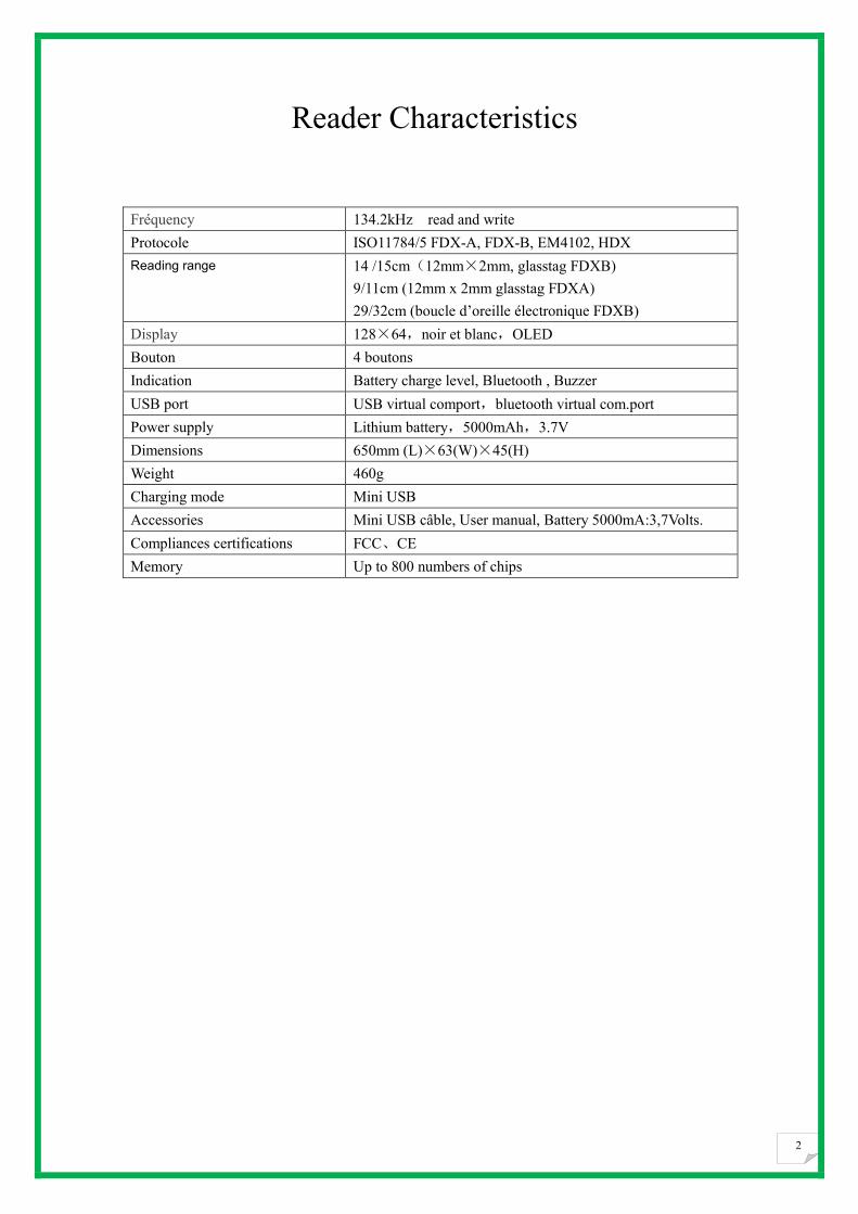
Reader Characteristics
Fréquency 134.2kHz read and write
Protocole ISO11784/5 FDX-A, FDX-B, EM4102, HDX
Reading range 14 /15cm(12mm×2mm, glasstag FDXB)
9/11cm (12mm x 2mm glasstag FDXA)
29/32cm (boucle d’oreille électronique FDXB)
Display 128×64,noir et blanc,OLED
Bouton 4 boutons
Indication Battery charge level, Bluetooth , Buzzer
USB port USB virtual comport,bluetooth virtual com.port
Power supply Lithium battery,5000mAh,3.7V
Dimensions 650mm (L)×63(W)×45(H)
Weight 460g
Charging mode Mini USB
Accessories Mini USB câble, User manual, Battery 5000mA:3,7Volts.
Compliances certifications FCC、CE
Memory Up to 800 numbers of chips

3
Table of contents
Characteristics of the V8BT………………………… pages 1/3
Changing the choice of language……………………………… page 4
Reading a chip « SCAN »……………………………………… page 5
Enable and disable Bluetooth………………………………… pages 6/7
The memory of the V8BT……………………………………… page 9
- enable the memory……………………………………… .page 10
- disable the memory ……………………………………… page 11
- erase the memory ………………………………………… page 12
Datas transmissions with a PC………………………………… pages 13 à 21
RealTrace Terminal……………………………………………..pages 22 à 27
Customization of the V8BT : displaying and Time out………..page 28/29
The « Woosit » system : writing a « chip »…………………...page 30
Realtrace Phone………………………………………………… pages 31 à 37

4
Configuration du lecteur RT 250 à la livraison
Le RT250 est d’origine configuré en anglais. Il est équipé d’usine d’un module de communication
sans fil bluetooth.
Il dispose d’une mémoire de 800 numéros. La fonction « Bluetooth » ainsi que la fonction
« Mémoire » ne sont pas activées à la livraison.
Si l’opérateur souhaite utiliser ces fonctions il devra donc les activer.
La fonction Bluetooth consomme de l’énergie. Il est donc conseillé de n’activer cette fonction que
le temps nécessaire à son utilisation.
A l’allumage un lecteur sera toujours dans la même configuration que lorsqu’il a été éteint.
La communication via Bluetooth est limitée à une dizaine de mètres. Elle dépend de
l’environnement et de votre PC. Pour l’activer sur votre PC veuillez consulter la notice de votre
ordinateur. Vous devrez désactiver la fonction sécuritaire de votre PC s’il vous est demandé
d’entrer un code ou entrer le code 1234 .

5
Language
Memory
English
English OK 5 secondes
Français
Français OK 5 seconds
Español
Español OK 5 seconds
Italiano
Portugues
Deutsch
Polish
Scan
Italiano OK 5 seconds
Portugues OK
5 seconds
Deutsch OK 5 seconds
Polish OK 5 seconds
Synoptics of menu “Language”

6
Synoptic menu « Scan »
After 25 seconds After 60 seconds
Charging indicator light
Reading
20 seconds max.
No transponder
found!
FDXB+ 939 2784879521125
Scan
Button In/Out
7
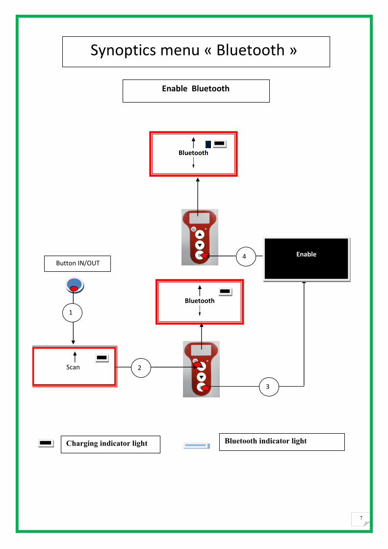
Bluetooth indicator light Charging indicator light
Scan
Enable Bluetooth
Bluetooth
Button IN/OUT
Bluetooth
Enable
1
4
3
2
Synoptics menu « Bluetooth »

8
Synoptics menu “Bluetooth”
Scan
Bluetooth
Button IN/OUT
Bluetooth
Disable
1
4
3
2
5
6
Scan
Disable Bluetooth
7

9
Using the V8BT Memory
The V8BTBT reader has a memory enabling it to store 800 identifiers (tag numbers).
This function must be activated by the user if he wishes to use it.
Storage of numbers read by the V8BTBT reader
The V8BTBT allows the user to store the numbers of the tags read in order to transfer them
subsequently to a PC using the USB cable included with the reader or with Bluetooth.
To use this function, you must first activate the “Memory” function (see block diagram: “Memory 1”).
When the Memory is activated each time a new tag is read, the reader displays the number but if the
same tag is read twice by mistake the reader indicates this by emitting a characteristic beep and
displaying “DUP” on the right of the screen.
This number will not be stored a second time.
If the reader is switched off, the memory function will still be activated when it is switched on again.
Deactivating the memory
The memory can be deactivated via the “Memory” menu.
Two cases may arise:
First case:
Numbers are recorded in the reader’s memory (Block diagram: Memory 3)
In this case you must transmit the list of recorded numbers actually or virtually (without plugging in
the USB cable) and then erase them .
Second case:
The memory has been previously activated but no number has been recorded.
In this case simply “deactivate” the memory (block diagram: “Memory 2”
Erasing the memory
To erase the contents of the memory to avoid errors, you must select the “Memory” menu and transmit
the list of recorded numbers actually or virtually (without plugging in the USB cable) and then erase
them (see Block Diagram: Memory 3).

10
Memory
Enable
Bluetooth enabled
Statement of the battery
Scan
Enable the Memory
M:0
Scan
Button IN/OUT
1
4
3
2 Press twice
Synoptics menu « Memory 1 »
1

11
Memory
Disable
M:0
Scan
Disable the Memory No chip registered
Scan
Button IN/OUT
1
2
3
4
Press twice
Synoptics menu « Memory 2 »

12
M:15
Memory
Send
M:15
Scan
Disable the Memory
15 chips numbers registered in the memory
M:0
Scan
Button IN/OUT
1
2
3
4
Press twice
Sending *****
Press “OK” to erase
Press “OK”
to confirm erase
If you don’t press « OK »
After 8 seconds
M:15
Scan
Erasing
******
5
6
Synoptics menu « Memory 3 »
13
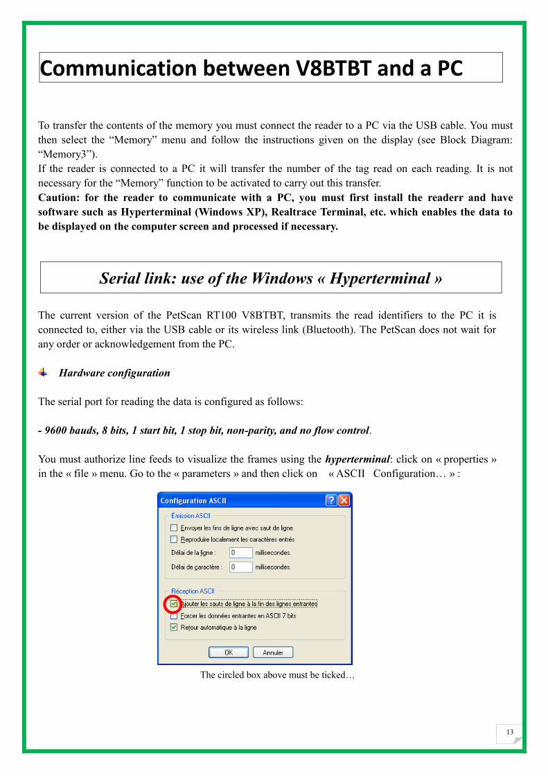
Communication between V8BTBT and a PC
To transfer the contents of the memory you must connect the reader to a PC via the USB cable. You must
then select the “Memory” menu and follow the instructions given on the display (see Block Diagram:
“Memory3”).
If the reader is connected to a PC it will transfer the number of the tag read on each reading. It is not
necessary for the “Memory” function to be activated to carry out this transfer.
Caution: for the reader to communicate with a PC, you must first install the readerr and have
software such as Hyperterminal (Windows XP), Realtrace Terminal, etc. which enables the data to
be displayed on the computer screen and processed if necessary.
Serial link: use of the Windows « Hyperterminal »
The current version of the PetScan RT100 V8BTBT, transmits the read identifiers to the PC it is
connected to, either via the USB cable or its wireless link (Bluetooth). The PetScan does not wait for
any order or acknowledgement from the PC.
Hardware configuration
The serial port for reading the data is configured as follows:
- 9600 bauds, 8 bits, 1 start bit, 1 stop bit, non-parity, and no flow control.
You must authorize line feeds to visualize the frames using the hyperterminal: click on « properties »
in the « file » menu. Go to the « parameters » and then click on « ASCII Configuration… » :
The circled box above must be ticked…

14
Description of the frame transmitted each time a transponder is read
The PetScan transmits the following frame to the PC after each valid reading :
Octet at the start of
the
frame : ″U″ ″/x55″
Type of 8
character
(or octet)
chip
The 16
character (or
octet) chip
identifier
Separation
of
octet: ″*″:
CRC-CCITT-control
word, 16 ASCII format
bits on 4 characters
Carriage
Return
octet: ″/x0D″
Tips: the developers of software associated with PetScan must use the head and separation characters to separate the
information transmitted by PetScan, calculate a control word with the data received and compare it to the word
transmitted by the PetScan to validate the information (see appendix for the CRC-CCITT-16 bit calculation
algorithm)
Description of the frames emitted when reading the databases (PetSCAN memory option)
If a PetScan reader has a memory option, when « Press SCAN to send » is displayed, the reader is ready to transmit
the identifiers stored in the memory. The PetScan displays « Sending ! » during transmission and the reader offers the
user the option of deleting the content of its database at the end of the transmission.
Format of the frames transmitted to the PC : the frame which is transmitted on each reading of a transponder is
preceded by a header octet ″/xAA″, its 4 character registration number in the memory and a separation
character ″*″.
Algorithm for calculating aCRC-CCITT-16bit control word
The C ANSI function’s source code enabling a control word to be calculated from a string of characters terminating
with the character ″/x00″ is described below. The JAVA applet on the « http://www.zorc.breitbandkatze.de/crc.html »,
website enables you to also calculate the control word. Previously the fields had to be correctly completed before
making the CRC calculation and a check made that the control word is equal to 0xE5CC or the ″123456789″
character string.
Start of
frame
octet : ″/
xAA″
4 character
registration
number
Separation
octet: ″*″
Start of
information
object : ″U″
″/x55″
The type
of 8
character
(or octet)
chip)
The 16
character
(or octet)
chip
identifier)
Separati
on of
octet: ″*
″:
CRC-CCITT-cont
rol word, 16
ASCII format bits
on 4 characters
Carriage
return
octet: ″/x
0D″
Data used to calculate the CRC
Data used to calculate the CRC

15
/*=======================================================================*/
/* Function that calculates CRC-CCITT 16 bits
/* INPUT:
/* unsigned char *inbuffer : 8 bits input vector over which CRC checksum is calculated
/* must termined by 0x00
/* OUTPUT:
/* unsigned int: 16 bits return of crc_ccitt checksum
/*=======================================================================*/
/* OVERVIEW:
/* Width = 16 bits
/* Truncated polynomial = 0x1021
/* Initial value = 0xFFFF
/* No XOR is performed on the output CRC
/* DESCRIPTION:
/* Computing a POLY number from the crc equation.
/* Crc s are usually expressed as an polynomial expression such as:
/*
/* x^16 + x^12 + x^5 + 1
/* CHECK
/* 0xE5CC This is the checksum for the ascii string "123456789"
/* EXAMPLE
/* http://www.zorc.breitbandkatze.de/crc.html
*=======================================================================*/
#define crc_poly 0x1021 // Polynome du CRC-CCITT-16Bits
unsigned int crc_ccitt16 (unsigned char *inbuffer) {
unsigned int crc_checksum = 0xffff;
unsigned char ch;
char i,xor_flag;
while ( *inbuffer!=0)
{
ch = *inbuffer++;
for(i=0; i<8; i++)
{
xor_flag=(crc_checksum & 0x8000)? 1:0;
crc_checksum = crc_checksum << 1;
if (ch & 0x80) crc_checksum++;
if (xor_flag) crc_checksum = crc_checksum ^ crc_poly;
ch = ch << 1;
}
}
for(i=0; i<16; i++)
{
xor_flag=(crc_checksum & 0x8000)? 1:0;
crc_checksum = crc_checksum << 1;

16
if (xor_flag) crc_checksum = crc_checksum ^ crc_poly;
}
return (crc_checksum);
}

17
How to know what USB port the V8BTBT is connected to.
(Windows XP)
When you connect a peripheral to a USB port on a PC, the PC automatically assigns it a port number. The peripheral is
often automatically recognised by the application software, thus it is not necessary to configure it. This is the case with
printers, scanners, etc.
Other types of application software need to have the communication port assigned by the PC indicated to them, in some
cases with other information such as the communication speed, the form of the data transmitted, etc.
As regards the V8BTBT, it is possible that the right port will be automatically assigned by the PC to the application
software, but it is also quite likely that you will have to choose it yourself from all the ports offered to you. You can of
course try them one after the other, but in some cases the PC’s peripheral configuration system will propose dozens of
them…
In this case we suggest a more rational method which will also allow you to check that your V8BTBT’s readerr is
correctly installed.
Select as shown below.
Then select « System »
Click!
Cliquez!

18
Then select « Device »
Then Select « Device Manager »
Then select « Ports (com et LPT) »
Click!
Cliquez!
Click!

19
The number of the Com port is shown.
Numéro du Port Com
auquel est connecté
le V8BTBT

20
How to know what USB port the V8BTBT is connected
to. (Windows 7/8)
Select as shown below.
Then select « System »
Click !
Click!

21
Then select « Device Manager »
Then select « Port COM et LPT»
The number of the Com port is shown.
The screens may be a little bit differents. It depends of the Windows version.
Click!
Click!
Com3 is the
number of Port
connected to the
RT250

22
RealTrace Terminal
This software is a tool supplied free of charge to all users of the RFID Realtrace standard (with
USB cable) or Bluetooth reader.
You can download this software following this link :
http://62.210.237.206/download/RealtraceTerminal.exe
You will find that once the communication has been established between a PC and the RealTrace
reader both appliances which were previously paired up remain connected providing that they are
separated by no more than 10 meters. The communication is cut if the distance is over 10 meters,
and a search and pairing up must be performed to restore transmissions.
The communication is also cut when the RealTrace reader switches off after several minutes on
standby to save energy in the battery.
The lost communication in both these cases is connected to the way Bluetooth technology operates
as well as the Windows operating system.
The use of a lithium/ion battery has provided a significant increase in the autonomy of the reader
(several thousand uses). Therefore, you can adjust the auto-power-off period as required: 2, 5, 10,
or 30 minutes or if you prefer, you can switch off the timeout altogether (not recommended). This
setting can be implemented the same way if Bluetooth is enabled. For your information, the reader
without auto-power-off, and with Bluetooth enabled works for over 48 hours.
http://62.210.237.206/download/V8BT-Timeout.exe
Initial parameterization of the « RealTrace Terminal » software
Sometimes, after installing Realtrace Terminal on your PC, you will have to parameterize the communication.
Sometimes it is not necessary but as safety precaution you can verify if all is correct. Click on « File » then
« Properties » then enter the USB port or Bluetooth’s communication port number as well as the following data :
- bits per second : 9600
- data bits : 8
- stop bits :1
- parity : none
- flow control : none
23
Using the software
Menu Options
Choose your language. You can choose between French, English, Spanish, and Chinese.
Select the data you want to appear:
- if you select "All data" it will show the type of chip (FDXB, HDX, FDXA) followed by the ISO
"smart" number and the CRC.
Example: UFDXB 939 000004095425*AC02
- If you do not select "All Data" only the ISO number of the "chip", or 15 numeric characters
(FDXB and HDX), or 10 Hexadecimal characters (FDX A) will be displayed.
Example: 939 000004095425
Do not forget to declare the type of keyboard you use - AZERTY or QWERTY - if not you risk having
inconsistent signs being displayed on the PC screen.
"File" menu
The "Save", "Delete" and "Exit" functions are classic.
The "Linking an application" function when selected allows you to link the data sent by the reader to the PC
to a Windows application (Word, Excel, etc.) and simultaneously display in the "RealTrace Terminal"
window.
If you want to save an Excel file, a number or a list of numbers stored in the memory of the reader you
must select "Linked to an application." You then have five
seconds to open your application, Word, Excel, etc. After this period if no application is opened data will
be sent to the Realtrace Terminal and appear on the initial screen.
"Connection" Menu
In case of breakdown in communication between the PC and the reader simply select "Connect" to
automatically reconnect.
Obviously for reconnection to be possible, the reader must be turned on and be within ten meters around
the PC, which must also be turned on.

24
Menu Realtrace Terminal
Language Selection
Keyboard Type
Communication Port Selection

25
Linking an application
Selecting application after the 5-second delay

26
Application open within 5 seconds: Excel
Connect!
Simple view: only ISO number

27
Showing all data.

28
Display message on reader startup! Setting the reader
power timeout!
Through its hardware design, the V8BTBT reader was intended to be easier to update, allowing
distributors and users to benefit immediately from upgrades that could better respond to market demands.
Now you can customise your readerthrough your PC by connecting to the http:// links that are listed below,
but be careful:
The V8BT customizer that provides for customising the welcome message upon starting the reader
only works from version VM14_v05
V8BTTimeout, which can set the time before automatic shutdown, only works from version
VM14_v6
Please note that you may find the version of the program installed in your V8BT by reading the "Master
Card Version V8BT" card that came with it.
1 / Display message on reader startup (V8BT Customizer)
This message could be your company name, customer name, date of sale or other text of your choice given
that you have two 16-character lines.
Upon starting the reader, the V8BTBT displays the recorded message for 4 seconds.
2 / Setting the reader power timeout. (V8BT timeout)
The use of a lithium/ion battery has provided a significant increase in the autonomy of the reader (several
thousand uses). Therefore, you can adjust the auto-power-off period as required: 2, 5, 10, or 30 minutes or
if you prefer, you can switch off the timeout altogether (not recommended). This setting can be
implemented the same way if Bluetooth is enabled. For your information, the reader without
auto-power-off, and with Bluetooth enabled works for over 48 hours
How to benefit from these options.
1/Just load the program option you are interested in on your PC, using the following links:
For the greeting:
http://62.210.237.206/download/V8BT_Customizer.rar
To set the power timeout
http://62.210.237.206/download/V8BT-Timeout.exe
2 / Connect the reader to the PC via USB cable

29
3/ Start the reader and open the program on the PC
For example, you can use this date as the validity of the start of the guarantee period
4 / Enter the fields on the screen and confirm (Write). The communication port is configured automatically.
The new settings will be implemented upon the next launch of the V8BT reader.
PS: Customising each reader takes a few seconds.
System « WOOSIT »
Writing the animal owner’s telephone number(s) in the ISO tag
Our wish to constantly innovate and improve our products has led us to offer vets the option of
personalising the tag, if they wish, before implanting it in the animal.
The main technological advance offered by this V8BTBT reader is that it will allow reading and display of
data which can be entered by the vet in the majority of the “tags” currently marketed worldwide, provided
that they comply with the ISO standard.
Realtrace has developed a system called “WOOSIT®
” which is comprised of:
- A reader /programmer the PetSCAN RT150 (1)
which enables the vet to write additional information to the “chip” before injecting it into the animal
(2).

30
- The PetSCAN V8BTBT which now offers the possibility to read and display the ID number but also to display additional data recorded by the vet in the memory as the phone number of the owner.
Due to the low memory capacity available in ISO chips (used up until then) the “WOOSIT” system is limited to the recording of one or two telephone numbers of 16 digits each. The vet and/or the owner of the animal may choose these numbers. This system is totally compliant with the ISO 11784/85 standard of 1996 in addition to the new 14223 standard* (May 2011) concerning the recording of data in advanced transponders. It protects the asepsis of the chip, as the writing of the data is carried out via the cap which protects the needle. If the owner prefers this, after the recording of one or two telephone numbers, the memory area used for this record can be blocked, making it impossible to delete or subsequently modify this information.
With the “WOOSIT” system, finding the owner of an animal will be particularly easy as reading the “chip” with the V8BTBT will provide the phone number(s) of the administrator of the database and/or the owner of the pet. Naturally, any pet owner who does not wish to use this service can simply enter nothing in the memory area of the chip, as is currently the case.
.
ID number and phones numbers
Iso Chip 11784/85 compatible with the possibility to write aditionals data (+)
(1)Patented
(2)sous réserve que les blocks 3/9/10/11/12/13 (EM4305) ou 9/10/11/12/13/14/15 (EM 4569) ne soient pas verrouillés
par le fournisseur de la « puce ».
*L'ISO 14223-1:2011 spécifie l'interface hertzienne entre l'émetteur-récepteur et le transpondeur évolué utilisé pour
l'identification des animaux par radiofréquence, à compatibilité ascendante totale avec les spécifications données
dans l'ISO 11784 et l'ISO 11785.
RealTrace-Phone Version 1.03 of 14 October 2015
This software is intended for distributors and veterinarians. It has been developed to allow the
reading and writing of data on the "chips" injected into animals, in accordance with ISO Standard
11784/85 and 14223.
The data to write, in this case one or two telephone numbers, is saved into memory blocks not
used by the 'chip', the ISO identification number (15 digits) having been written and locked by the
manufacturer. It is therefore imperative that some blocks are available, and therefore open, so
the procedure of writing using the V8BT reader can be correctly achieved.
This additional information can be written to the 'chip' in the needle,through the cap, either before
injection of the transponder into the animal or in the animal after injection.
We recommend that you write the number(s) in the needle, and then by reading, check the
accuracy of what has been written and then inject the chip to the animal.

31
When reading from a 'chip' that contains no phone numbers the reader emits a single “beep” when
it has found the chip.
If the "chip" contains or has contained telephone numbers, the reader emits two “beeps”.
In the event that the owner of the animal should change phone number, it will be possible to
update the numbers by overwriting the "chip" implanted in the animal. The write and read
distance for additional data on the chip by the V8BT reader is about 7 to 9 centimetres that is
slightly less than the distance for reading the ISO number (10 to 12cm).
The PC program allows the entry of two 16-digit sequences, i.e. two phone numbers. We advise
to register these numbers indicating the ISO code of the country.
Example: 0033134618980 (do not put spaces between numbers)
The choice of telephone numbers is left to the discretion of the user: the number of the owner of
the animal, of the veterinary clinic, of an association, etc.
These numbers can be changed by the veterinarian as many times as necessary.
What is the essential equipment?
1/ The implanters, needles, and "chips" are the same as those currently used by veterinarians.
“Chips” may be standard size; that is 2 x 12mm or the smaller 1.4 x 8.5 mm format that is
currently gaining on the market.
However, whatever format is selected, the "chips" delivered by manufacturers must be
programmed with the locked ISO identification number, with blocks 3/9/10/11/12/13 open.
These currently unused blocks will be used to save the phone numbers and signature.
2 / A conventional PC running XP, Windows 7 or Windows 8. The PC must have a USB
connection and possibly Bluetooth connection.
3/ An RT100 PetScan V8BT reader with its USB cable.
4/ Realtrace-Phone software, which is provided free of charge.
Installing the Realtrace-Phone software
http://62.210.237.206/phone/phone.html
The installation of the software and the readerr are done automatically on the PC. Just follow the
instructions given by the messages on the screen, like the installation of a printer or a scanner.
After installation an icon will appear on the PC desktop.
Using the Realtrace-Phone software
Phase 1 Connecting the V8BT and opening the RealTrace-Phone program.
Connect the V8BT to the PC using the USB cable, turn on the reader (display shows "Read") and
then the computer monitor, click on the icon and the following window will open on the
screen:

32
It is possible that when connecting the V8BT to the PC that an update the software resident in
the V8BT is carried out automatically. Wait until the loading has ended before continuing.
Phase 2 language selection
Click on the "Language" tab and select the language of your choice: English, Spanish or French.
Phase 3 Find communication port
At the bottom of the screen to the right is a "Configuration" window, it may say "Automatic" or on
opening the window "USB COM 5". This port number 5 is the one used on our PC. It could well
be different on your PC.
A search of all available COM ports on the PC takes place automatically. You can stay in
automatic search, but if you have a lot of COM ports open on your PC, you can select it in the
window to expedite the allocation process.

33
Step 4 Reading a "chip"
Make sure the V8BT connected to the PC is still on. In order to preserve the energy of the battery
to a maximum, the reader is programmed to turn off after two minutes if no key has been activated
during this time.
So if it is off, turn it on and read a chip, either through the needle or on the animal. During this
reading it is not necessary for the V8BT to be connected to the PC.
The number of the "chip" appears on the screen on first line of the reader, possibly followed by
one or two lines of numbers corresponding to the phone number(s) (if reading a chip where
number(s) have been programmed).
Please remember that the first three digits of the "chip" indicate either the ISO country code (250
for France) or the manufacturer's ICAR code.
You will need to send this data to the PC.
Reconnect the V8BT to the PC if it was disconnected and then click the window at the bottom left
of the screen that says:
After two or three seconds the following screen appears:
Reading
Read

34
Or this one, if the "chip" already had phone numbers:
Confirm by clicking OK
Phase 5 - Enter one or two phone numbers using the PC
Depending on what you want to do you will either need to enter the phone numbers you want to
write into the chip or modify those already saved to it.
If you make a mistake click delete and start typing again.

35
We recommend that you enter the full number with the prefix 00, then the country code.
Make sure the phone numbers entered are correct then click on the windows as required:
After two or three seconds the following screen appears:
The PC has transmitted the data to be saved to the "chip" to the V8BT using the USB cable or
Bluetooth.
A message informs you that you can disconnect the reader from the PC to write to the "chip".
This disconnection is not essential if you want to write to the "chip" in the needle but is advisable
if you want write to a "chip" already injected into an animal.
Phase 6 - Data entry by V8BT
At the same time as the message appears on the PC, the V8BT display indicates:
The reader seeks the chip in which it should write ...
Write phone 1
Approach the reader to the
chip and validate by
pressing the centre button
to write
Write phone 2 Write phone 1 + 2

36
Three possibilities:
1/ If the reader does not find the "chip" after 20 seconds of searching ...
Search other time
2/ If the reader has found the "chip" it must write to
Back to Main Menu
We recommend that you re-read the injected chip to verify that the data has been recorded, given
that if the entry has been done correctly in the "chip" V8BT displays the following message:
Very often this happens when one or more memory blocks needed to record phone numbers are
closed in the "chip" so it is impossible to write.

37
Or:
You tried to write into another "chip" than that previously read,
Note: be careful not to discharge the battery by leaving the V8BT showing the message:
This is the only case where the V8BT does not turn off automatically! To return to the menu,
press the In / Out button.
Operating problems:
1 / When switching on the V8BT displays the message and turns off
immediately.
The battery is almost discharged. You need to charge it.
2/ When switching on the reader the screen stays black:
- either the battery is totally discharged: leave it to charge.
- or the V8BT is no longer working. In this case an extended press on the In/Out button will
shutdown the reader with two "beeps". Send the reader back to After Sales.
3/ A message, whether or not intelligible remains displayed. Pressing buttons has no effect. The
program has "frozen"…
In this case you need to disconnect the battery very carefully, without pulling on the wires, and
wait a few seconds before re-connecting it.
4/ The V8BT will not switch on, even after charging: return to our After Sales service.
Very important: this reader has the latest technology in terms of power supply. The
Lithium/ion batteries should only be recharged using an USB power supply. Be careful to
never short circuit the battery.
Low battery