George Ainslie - A Research-based Theory of Addictive Motivation

Petroworth Resources Inc.
Petroworth West Ainslie No.1 West Lake Ainslie, Inverness County, Nova Scotia, Canada
Technical Report
To accompany
Application for An Authority to Drill
(NSDE Exploration Agreement No. 04-07-15-03)
Submitted to: Nova Scotia Department of Energy
Canadian Petroleum Engineering Inc. Calgary,
Alberta, Canada
W.G. Shaw & Associates Ltd. Antigonish,
Nova Scotia, Canada
September 21, 2010
TABLE OF CONTENTS
1.0 Well Information p. 03
1.1 Introduction p. 03
1.2 The Drill Site p. 05 1.3 Geologic Prognosis p. 07
1.4 List of Contractors p. 08
2.0 Evaluation Program (Logs, Cores, Tests)

p. 09
3.0 Drilling and Casing Program p. 10
3.1 Introduction p. 10 3.2 Surface Hole Procedures and Policies p. 13
3.3 Main Hole Procedures and Policies p. 17
3.4 Production Casing Program p. 18
4.0 Cementing Program p. 21
5.0 Special Terms and Conditions p. 24
6.0 Authorization p. 24
7.0 Liability p. 24
8.0 Attachments Required p. 24
Appendices Appendix A Surface Lease Agreement p. 26 Appendix B Nabors Rig
#112 - Specifications p. 33 Appendix C Emergency Response Plan p. 37 Appendix
D Environmental Management Plan p. 46 Appendix E Canadian Petroleum
Engineering Inc.
Safety and Environmental Policy p. 58 Appendix F Survey Plan
of Surface Lease p.
1.0 Well Information
1.1 Introduction
Petroworth Resources Inc. is planning to drill a conventional petroleum
exploration well (Drill Site) in southwestern Inverness County, Nova Scotia for the
purpose of evaluating the petroleum potential of a prospect that has been outlined
by previous exploration work, including a reflection seismic program conducted in
the summer of 2009. The proposed Drill Site is immediately east of the West Lake
Ainslie Road on a property owned by Mr. Ken MacDonald of the village of West
Lake Ainslie (Surface Lease is presented in Appendix A). The Drill Site is located at
Easting: 640,155 m (NAD 83), Northing: 5,106,602 m (NAD 83) and ground
elevation is 85 metres (amsl).
Petroworth is a junior oil and gas company, committed to safeguarding

the welfare of on-site, personnel, the public and the environment through the
application of best practices in their operations and by meeting or exceeding
regulatory guidelines.
Figure #1 Location of proposed well site on map of Cape Breton Island, Nova
Scotia
Petroworth Resources Inc. has held a Petroleum Exploration Agreement
(No. 04-07-15-03) in southern Inverness County, Cape Breton Island since 2004 (Figure #1). Over the past several years, Petroworth has conducted geological
mapping, a soil gas survey, a gravity survey and in Year 2009 collected 90
kilometres of reflection seismic data in the agreement area.
Drilling is scheduled to begin at the West Lake Ainslie No.1 drill site in
mid-November of 2010, with completion in about 14 to 20 days. It is expected
that the well will be terminated at a depths of from 1,200 to 1,500 meters.
Drilling services have been contracted to Nabors Drilling Ltd. (Drill Rig
#112) under the direction of Canadian Petroleum Engineers Inc. (Appendix A).

Figure #2 Location of proposed well site on map of southern Inverness County,
Cape Breton Island, Nova Scotia
1.2 The Drill Site
The Petroworth West Ainslie drill site will consist of the following :
An access road will be constructed from the West Lake Ainslie Road to the
drill pad which will be located 200 metres to the east of the road. A 100 metres by 75 metres drill pad will be constructed by removing the
topsoil, leveling, laying a liner and built-up using locally-sourced gravel followed
by leveling and compacting. The access road and pad will be constructed on land currently used as a hay field. Surface drainage is by overland flow toward the
northeast.
The Nabors #112 drill rig will be constructed on the pad with the wellhead
located near the center of the pad. An emergency flare system (pipes will be located south of the wellhead. A cement pit (approximately 3x3x3 m in size) for
handling the cement returns during drilling will also be constructed near the
wellhead. The site trailer and four or five support shacks will be lined up along one side of the pad. There will also be a freight van for drilling mud storage. A septic
holding tank (plastic) for wastewater (grey and black) will be located behind the
trailers.

In the event of an unsuccessful exploration well, demobilization of
equipment and site abandonment and reclamation will occur immediately after completion of the well. Petroworth will consult the Nova Scotia Departments of
Energy and Environment and utilize good oilfield practices to plan abandonment
of the well bore and reclamation of the lease site.


Figure #3
1.3 Geologic Prognosis
Petroworth West Ainslie No.1 will be spud in the Ainslie Formation which is
the upper part of the Horton Group. The Ainslie Formation is dominated by
greyish-green and reddish-grey, fine grained sandstones that are interbedded with
reddish-brown coloured siltstones. At approximately 300 metres depth, the well is
expected to enter the Strathlorne Formation which is dominated by grey and dark
grey coloured shales, mudstones and siltstones with lesser amounts of
interbedded, grey coloured sandstones and minor, thin carbonate beds. At
approximately 800 metres the well may enter the Creignish Formation which is
dominated by reddish-brown and grey coloured conglomerate and pebbly
sandstone with lesser amounts of reddish-brown coloured, find grained sandstone
and minor siltstone

1 List of Contacts
2 Evaluation Program (Logs, Cores, Tests)

Schlumberger Logging has been contracted to conduct borehole
geophysical logging after completion of the well. Petroworth plans to run

Schlumberger's “Platform Express + Sonic” suite of logs (compensated sonic,
induction electrical conductivity, compensated density and neutron density).
No cores are planned for this well.
Formation testing may be conducted after completion of the borehole
logging program if favourable intervals are identified by petrophysical analysis. 10
3.0 3.1
Drilling and Casing Program Introduction
Casing Design
Dept
h (m)
Size
(mm)
Weight
(kg/m)
Grade Couplings
Surface 175 219.1 35.7 J-55 ST&C
Intermediate
(Contingency )
Production 1400 139.7 25.30 L-80 NK3SB
Summary of Operations
1 Notify Contractors of date of anticipated rig move.
2 Hold Pre-Spud safety meeting with all involved personnel.
3 Drill and set +/-15 meters of 340 mm conductor prior to MIRU. 4 Notify Nova Scotia Department of Energy of intended spud date.
5 MIRU and drill 175 meters of 269.8 mm surface hole with floc water. Mud
up with gel/chemical mud as per mud program if required. 6 Double strap out of hole on wiper trip before logging.
7 Logging program for surface hole will be provided.
8 Run 175 meters of 219.1 mm 35.7 kg /m surface casing and cement to surface.
9 WOC; RIH and drill out shoe with water.
10 Displace the well to clay free polymer mud system as recommended in Mud
program 11 Drill 200 mm hole with mud to drill from the surface casing shoe to TD. Be
vigilant through this section.
12. Survey from beneath the surface casing shoe at intervals not to exceed 100 m. More frequent surveys may be taken if the hole shows any
indication of building angle.
12 POOH, condition mud and log as per logging program. Double strap on this
trip.
13 Conduct clean out trip prior to running casing. 14 Depending on the results of the well logging, up to 2 DST‟s may be run. This
will be determined after logging is completed.
15 RIH with 139.7 mm, 25.30 kg/m L-80 production casing. Torque monitoring of each connection will be required.
16 Cement casing to surface as per regulatory requirements. Cement program
may be a two (2) stage (i.e. fill/tail) cement job to ensure good cement bond to surface.
17 Install wellhead if well is to be left suspended.
18 Circulate wellbore to inhibited water after cementing so that no
contaminants are left in the wellbore long term. 19 Close all wellhead valves, chain and lock.
20 Rig out drilling rig.
Potential Problems
1 Minor water flows in the surface hole section. 2 Lost circulation is possible if rocks, gravel or boulders are encountered.
3 Deviation could be a problem on surface hole if unconsolidated formations
are encountered.


3.2 Surface Hole Procedures and Policies
1 Drill a minimum of 10 m of conductor hole. Set and cement in place a 340
mm conductor pipe with a 50 mm drain value installed below ground level. Install a cribbed cellar and a 203 mm cellar drain to sump.
2 Rig up rig as per Nova Scotia Department of Energy rig layout requirements
and Rig Inspection manual. Conduct a thorough rig inspection prior to beginning operations and record in tour book.
3 Spud with water and build viscosity to 40 to 60 s/l with gel to reduce
washing and subsequent sloughing of surface sands. Drill ahead 269 mm hole. 4 Watch for lost circulation problems on surface hole. If severe lost circulation
occurs, consult with Calgary office.
5 Survey first 9, 18 and 27 m and every 30 m thereafter or as required to
maintain surface deviation at or below 1.0 degree. If deviation becomes a problem and exceeds 1.0 degree per 30 meters, contact Calgary office Drilling Manager.
6 Raise viscosity to 65+ s/l ten meters before T.D. Trip out of hole.
7 Measure and check tally out of hole. If over 0.6 m out, measure back in. 8 Drill to surface T.D. at 175 m KB +/- 1.0 m.
9 Measure kelly to assure total depth is correct.
10 Circulate hole clean, working pipe at T.D. at least two full circulations or until the hole is clean as indicated by the cuttings coming over the shaker. Hoist
to run 219.7 mm casing.
11 Ensure proper tripping practices are performed, all trip records are complete and hole fill and return volumes are monitored correctly.
Deviation
Deviation is not to exceed 1°. Surveys to be taken every 30 m and recorded.
Ensure hole is drilled below any gravel or boulders to ensure a good casing seat. If
lost circulation does not occur solids control equipment may be used.
Mud
If lost circulation occurs, build viscosity to 100+ and add LCM. Pump
down at reduced rate until circulation is established.
Options
If circulation cannot be established, and water supply is good and well conditions permit, drill blind while mixing up lost circulation pills.
If compete circulation is lost, Calcium Carbonate LCM plugs should be tried
as they have been successful in regaining circulation and they are acid soluble. If above fails a cement or diesel gel plug may be considered.
If gravel has been a problem, reducing mud properties may compromise the
hole. Cement with mud properties required in drilling.

Hydraulics
Run mud pump, as required, to maintain adequate annular velocity to clean
hole. A pump rate of 1.75 to 2.50 m3/minute should provide sufficient annular
velocity for hole cleaning. Drill to within 10 m of casing setting depth, circulate
hole clean, double strap out, check tally against strap. Drill to casing setting
depth, circulate and wiper trip to achieve good hole conditions for casing.
Surface Casing Program
1. Run 219.10 mm, 35.7 kg/m, J-55, ST&C surface casing from bottom up as follows:
i. 219.10 mm guide shoe
ii. one joint 219.0 mm, 35.7 kg/m, J-55, ST&C casing
iii. 219.1 mm float collar
iv. X joints 219.10 mm, 35.7 kg/m, J-55, ST&C casing to surface.
2. Running procedures to be followed:
i. Visually inspect all joints of casing for thread and tube damage.
ii. Tally and drift casing with API drift.
iii. Threadlok float shoe, first joint of casing, and float collar.
iv. Install centralizers, one on shoe joint and one each casing collar for
minimum 3 joints above float collar then every third collar to surface. v. Use API modified thread compound on all casing strings.
vi. Set casing 150 to 200 cm (6”) off bottom. Tie down casing while
cementing. Note: If severe lost circulation occurs, discuss installation
of cement baskets above loss zone with Calgary office.
Surface Casing Properties
Casing 219.1 mm, 35.7 kg/m, J-55 ST&C
General Information:
Inside Diameter (mm) 206.66
Drift Diameter (mm) 202.49
Capacity (m^3/m) .00456
Collapse Resistance (MPa) 9.45
Internal Yield Pressure (MPa) 20.34
Pipe Body Yield Strength (1000
1695
N)

Joint Strength (1000 N) 1085
Make-Up Torque Kg-m (ft-lb)
Casing Minimum Kg-m
(ft-lb)
Optimum Kg-m
(ft-lb)
Maximum Kg-m
(ft-lb)
219.1mm, 35.7 250 (1830) 340 (2440) 420 (3050)
kg/m, J-55 ST&C
BOP Rig Up and Pressure Testing
Cut and trim casing and weld on Cameron „IC-2‟ 219.1 x 228.6 mm, 21 MPa
series slip on casing bowl. Let bowl cool and pressure test welds to 10,000 kPa.
Ensure casing bowl is set above ground elevation.
BOP Stack Up
The BOP stack to be used on this well will be a double gate 21,000 kPa,
228.6 mm full opening stack.
Nipple up BOP‟s as per Nova Scotia Department of Energy regulations. Perform blowout drill prior to drilling out and record results in tour sheet.
Each remaining crew to perform and record BOP drill as soon as possible after
drilling out. Tank level monitors must be hooked up and operational prior to drill out.
A daily visual rig inspection must be done with time and results noted in
tour book.
BOP Pressure Test
Pressure test blind rams and manifold valves individually to 1,400 kPa low
and 14,000 kPa high for 10 minutes with no more than a 10% pressure decline. Check motor shutoffs and remote controls. Pressure test pipe ram and annular
preventer and HCR to 1,400 kPa low and 14,000 kPa high for 10 minutes with not
more 10% pressure decline.
A BOP Drill shall be held prior to drilling out the surface casing shoe.
BOP drill to be performed by crew on tour and by each crew as they come on
tour and recorded. After drilling out, BOP‟s must be function tested and recorded
daily.
A two page Pre-Drill out, weekly Rig Inspection Report and Daily Rig

Inspection report to be completely filled out.
Gas Detection System
PetroWorth Resources Inc. proposes the installation of the following Gas
Detection System on the Nabors 112 Drilling Rig. The gas detection system will
be a Rig Rat H2S / LEL Hardwire Multipoint system. The Rig Rat system consists
of the following:
1 A four or eight channel continuous monitoring system used most
commonly to detect LEL and / or H2S levels.
2 The system uses 110 volt power and includes 150 to 300 feet sensor cables.
3 The rig rat system allows for the installation of other sensors which detect
carbon dioxide (CO2), Sulphur dioxide (SO2), carbon monoxide (CO) and ammonia, as well as oxygen deficiencies. Some of these sensors may be installed dependent
on perceived need.
4 Low and High alarm values can be reset as required for the required gas detection with configurable alarm points.
5 Low and High alarm visual bars can be coordinated to each of four
sensors.
6 The system has a response time of less than 10 seconds to full alarm.
3.3 Main Hole Procedures and Policies
Drill Out
Drill out casing with water using 200 mm bit and low weight and rpm. Drill
5 m of new hole. Conduct P.I.T. and post in doghouse and manifold shack. If
M.A.C.P. is estimated use 18 kPa/m for casing set to 250 m; 22 kPa/m for deeper
setting depths.
Drill ahead to approximately 1400 m K.B. or as stipulated by the wellsite
geologist.
Deviation/Direction
A survey will be taken 15 meters below the surface casing shoe. Survey
again 30 meters, 60 meters and 120 meters below surface casing shoe. Survey
every 100 m or as required to TD, deviation not to exceed 3°.
Mud

The main hole section will be drilled with a PHPA clay free polymer
system. Drill out casing shoe with water. Have mud tanks full of premixed
mud to displace hole as soon as cement is drilled out. Displace hole to PHPA
mud system as per mud program.
Note: Evaluate whether mud system can be watered back with use of the
centrifuge and dilution prior to drilling out in order to minimize amount of waste
mud to be discarded.
Make up water properties are very important as excessive salt or hardness
in the make up water will interfere with the hydration and reduce the
effectiveness of the polymers.
Maintain the fluid loss at less than 20 cm3/30 min initially and then
decrease water loss to 12 cm3/30 min for the entire hole interval to reduce spurt
loss and flushing around the borehole. It is very important that all the solids
control equipment perform effectively for the main hole section. This includes the
King Cobra shale shaker, all mud mixing equipment and the rental centrifuge.
Lost Circulation
The potential for lost circulation is unknown in the main hole section;
however it is always possible. Refer to Mud Program for the treatment plans.
Hydraulics
Standard parameters for hydraulics are as follows:
Flow rate 4.6-7.6 1pm/mm of bit diameter
Bit pressure drop 50-65% of surface pressure
HHP/in2 2.5-5
Every attempt should be made to ensure an annular velocity of
3540m/min. to provide sufficient hold cleaning. Actual hydraulics to be
calculated at well site.
General Guidelines
Production Casing will be 139.7 mm, 25.30 kg/m NK3SB set at approximately
1400m K.B. as per Program.
Inspect and clean threads, drift and tally casing. Ensure count matches manifest
and joints are undamaged. Inspect float equipment to ensure threads are
compatible, undamaged and valves are operable and junk free. Number running
order of casing with yellow chalk. Review running order, torque requirements and
centralizer placement with power tong contractor and with casing pressure testing

personnel.
Run with a float shoe on bottom and a float collar one joint above the shoe. Threadlock the first two or three joints. Each joint of the casing will be internally
pressure tested as it is made up to ensure the sealing integrity of the casing string.
3.4 Production Casing Program
General Guidelines
Production Casing will be 139.7 mm, 25.30 kg/m NK3SB set at approximately 1400m K.B. as per Program.
Inspect and clean threads, drift and tally casing. Ensure count matches
manifest and joints are undamaged. Inspect float equipment to ensure threads are
compatible, undamaged and valves are operable and junk free. Number running
order of casing with yellow chalk. Review running order, torque requirements and
centralizer placement with power tong contractor and with casing pressure testing
personnel.
Run with a float shoe on bottom and a float collar one joint above the shoe.
Threadlock the first two or three joints. Each joint of the casing will be
internally pressure tested as it is made up to ensure the sealing integrity of the
casing string.
Procedures
Run 139.70 mm, 25.30 kg/m, L-80, NK3SB production casing from bottom
up as follows:
139.70 mm guide shoe • one joint 139.70 mm, 25.30 kg/m, L-80, NK3SB casing
139.1 mm float collar
X joints 139.70 mm, 25.30 kg/m, L-80, NK3SB casing to surface. Running procedures to be followed:
Visually inspect all joints of casing for thread and tube damage.
Tally and drift casing with API drift. Threadlok float shoe, first joint of casing, and float collar.
Install centralizers, one on shoe joint and one each casing collar for
minimum 3 joints above float collar then every third collar to surface. Use API modified thread compound on all casing strings.
Production Casing Properties

Casing 139.70 mm, 25.3 kg/m, L-80, NK3SB
General Information:
Inside Diameter (mm) 124.26
Drift Diameter (mm) 121.08
Capacity (m^3/m) .00323
Collapse Resistance (MPa) 43.30
Internal Yield Pressure (MPa) 53.37
Pipe Body Yield Strength (1000
1766
N)
Joint Strength (1000 N) 1984
Make-Up Torque Kg-m (ft-lb)
Casing Minimum Kg-m
(ft-lb)
OptimumKg-m
(ft-lb)
Maximum Kg-m
(ft-lb)
139.7mm, 25.3 kg/m, L-80 NK3SB
410 (3000) 480 (3500) 690 (5000)
Circulating
Circulate casing at least three complete circulations, at same annular velocity as hole was drilled, until shakers are clean. Lower PV and YP to minimum
safe values prior to cementing. Reciprocate casing 2 to 4 m while circulating at 1
cycle/min. Reciprocate casing 13 to 14 meters every 3rd
cycle so that the collars
overlap travel in open hole.
4.0 Cementing Program
Surface Cementing Program
1 Ensure that the mix water is between 150C and 30
oC to prevent viscous
cement slurries.
2 Circulate casing at least three complete circulations, at same annular
velocity as hole was drilled, until shakers are clean. Lower PV and YP to minimum safe values with water prior to cementing. Reciprocate casing 2 to 3 m while
circulating at 1 cycle/min. On every 3rd
cycle, reciprocate casing 13 to 14 meters to ensure collars travel over location of next collar.
3 Pressure test surface lines to 21 mPa prior to proceeding with cementing

operation.
4 Precede cement job with 5.0 m3 of water preflush.
5 Cement with 50% excess using Class “G” + 3% CaCl2 or with 20% over
caliper, whichever is greater. Ensure at least one dry sample, and three cement slurry cement samples are caught during the cementing operation and a minimum
of 2 samples of final returns @ the surface in the event there are complications
with the job. See attached cementing program for specific details. (excess may change due to drilling conditions, lost circulation, consult with the drilling
department prior to ordering out surface cement)
6 Use wooden plug to displace cement. 7 Measure displacement while cementing. Slow pump rate near the end of
displacement and bump the plug using 3500 kPa (500 psi) over final pumping
pressure. Hold pressure for 2 minutes, then bleed back casing pressure to ensure float is holding.
8 Record cement returns, KB to ground in tour book and on Canadian
Petroleum Engineering Inc. daily drilling reports (note: take into account any cut
or fill during construction that would change the pin elevation). 9 If cement returns are not obtained, immediately re-cement with 25.4 mm
pipe behind casing. Note: Have a supply of 25.4 mm pipe available on surface. In
all cases, catch samples of last returns. 10 Check cement quality before slack off. Slack off, cut casing and head up in 8
hours. Wait on cement a minimum of 12 hours prior to drilling out. At all times,
ensure casing is centered within the rotary table. 11 Provide Service Company with a sample of water at the time of surface
cement job for compatibility testing with production cement blends.
If lost circulation occurs while drilling surface hole, consideration should be
given to:
Add LCM (gel flake) to cement slurry.
Increase excess cement to 100%.
Pump a light scavenger slurry rather than water ahead. of cement Slow down displacement rate.
Run cement baskets at selected intervals.
Production Cementing Program
Ensure that the mix water is between 150C and 30
oC to prevent viscous
cement slurries.
1 Circulate casing at least three complete circulations, at same annular velocity as hole was drilled, until shakers are clean. Lower PV and YP to minimum
safe values with water prior to cementing. Reciprocate casing 2 to 3 m while
circulating at 1 cycle/min.

2 Pressure test surface lines to 21 mPa prior to proceeding with cementing
operation.
3 Precede cement job with 4.0 m3 of water preflush.
4 Follow with 3.00 m3 (2.27 tonnes) of Fill-Lite 2-100 as a scavenger.
Scavenger should be mixed at a density of 1518 kg/m3. Scavenger should contain
0.90% FL-5, 2.00% A-11 and 2.00% A-9.
5. Cement with 30% excess using Fill-Lite 2-100 + 0.90%FL5-5+2.00%A-11
+ 2.00% A-9 Accelerator. Ensure at least one dry sample, and three cement
slurry cement samples are caught during the cementing operation and a minimum of 2 samples of final returns @ the surface in the event there are complications
with the job. See attached cementing program for specific details. (excess may
change due to drilling conditions, lost circulation, consult with the drilling department prior to ordering out production cement)
5 Use rubber plug to displace cement. Slow pump rate near the end of
displacement and bump the plug using 3500 kPa (500 psi) over final pumping
pressure. Hold pressure for 2 minutes, then bleed back casing pressure to ensure float is holding.
6 Record cement returns, KB to ground in tour book and on Canadian
Petroleum Engineering Inc. daily drilling reports (note: take into account any cut or fill during construction that would change the pin elevation).
7 Check cement quality before slack off. Slack off and head up in 9 hours. At
all times, ensure casing is centered within the rotary table. 8 Provide Service Company with a sample of water at the time of surface
casing cement job for compatibility testing with production cement blends.
If lost circulation occurs while drilling main hole section, consideration
should be given to:
Add LCM (gel flake) to cement slurry Increase excess cement to 100%.
Pump a light scavenger slurry rather than water ahead. of cement
Slow down displacement rate.
5.0 Special Terms and Conditions
Special terms and conditions are provided by the Nova Scotia Department of
Energy and the Nova Scotia Department of Environment.
1 Authorization

2 Liability
Petroworth Resources Inc. will conduct all operations are conducted in a
prudent and reasonable manner, consistent with good petroleum exploration
practices. Petroworth indemnifies and saves harmless the Province from any and
all claims, demands, losses or damages from death, actions or suites that may
arise out of or as a result of anything done in the carrying out of exploration
conducted under the Authority to Drill a Well.
8.0 Attachments Required
8.1 Financial Security
8.2 Proof of Consent to Drill on Land
A copy of the signed surface lease agreement with Mr. Ken MacDonald is
provided in Appendix A.
Appendix B
Nabors Rig #112 - Specifications


Appendix C

Emergency Response Plan
Petroworth Resources Inc.
West Ainslie No.1
Emergency Response Plan
Introduction
The Petroworth Emergency Response Plan (ERP) has been developed to
address specific conditions related to the drilling of an exploration well in the
vicinity of the Community of West Lake Ainslie, Cape Breton Island, Nova
Scotia.
The Petroworth ERP is designed to compliment the ERPs put in place by
the drilling contractor and subcontractors to ensure the interests of the public are
protected and the public and regulatory agencies are properly informed of events
in an accurate and timely manner. Therefore, this document is an extension of
and an integral part of any site specific drilling, completion, facility or Area
Emergency Response Plan.
With the development of this Nova Scotia Operations Emergency
Response Plan, the Company is prepared to:
Ensure immediate, competent responses and handling of an emergency Minimize danger to the public, Company employees or Contractors
Maintain effective communications with all parties in an emergency
Make maximum use of the combined resources of the Company, the
Government and other services
Emergencies
An “Emergency” is defined as any unplanned occurrence resulting in, or
having the potential to result in: death, critical injury, a threat to the safety of
public and/or Company/Contractor personnel, major or significant damage to
Company property and operations, or pose a potential impact to the environment.
Examples include:

. Oil or Chemical Releases – the potential for, or actual hydrocarbon or
chemical spill, or other emissions affecting company operations and/or threatening adjoining property.
. Critical Injury / Fatality – any event that results or could result in loss of
life, critical injury, or missing personnel (OHSA critical injury defined)
. High / Low Vapour Release – the potential for, or uncontrolled flow of
hydrocarbon gases or LPG‟s from a well, pipeline, tank or other facility
affecting Company operations and/or adjoining property
. Explosions or Fires – a potential explosion / fire or actual explosion / fire
that cannot be extinguished or controlled by readily available means and which is affecting Company operations and/or threatening adjoining
property
. H2S Release – the potential for, or uncontrolled flow of sour gas or liquids
from a well, pipeline, tank or other facility affecting Company operations
and/or threatening adjoining property (only relevant to operations involving H2S or the potential to encounter H2S)
. Security Breach – A threatening telephone call, note or other form of
communication involving such issues as extortion, bomb threats or acts of terrorism
Stages of Emergency
The following stages of emergency and their respective examples are for
illustrative purposes only and are NOT to be construed as a definitive listing.
Level #1 Emergency (Potential Emergency)
Definition
Any situation which is limited to the boundaries of Company property,
and the personnel on-site have the ability to regain control. No danger to the
general public exists.
. No danger outside company property
. Immediate control of hazard/source . No immediate danger to public exists
. Minimal environmental impact
. Situation controlled entirely by company personnel
Response Actions . Senior Onsite Supervisor and/or alternate field personnel are
dispatched to the emergency site to evaluate the situation;
. A Level #1 – Potential Emergency is declared, and control procedures are initiated;
. Company Emergency Response Members, appropriate field personnel,
the MNR, RCMP and local authorities (if warranted) are advised that a Level #1 Emergency has been declared;
. Depending on severity of potential escalation, specialized equipment &
personnel, air quality monitoring, emergency shutdown procedures, etc. may be
put on standby. . All response team members maintain 24 hour availability.
Level #2 Emergency
Definition
Any situation where the event extends beyond the boundaries of Company
property, and/or control cannot be quickly accomplished. Some danger to the
general public exists.
. No immediate danger outside company property, potential exists for emergency to extend beyond company property
. Outside services and Provincial Government agencies must be alerted
. Imminent control of hazard is probable
. Moderate environmental impact
Response Actions
. Senior Onsite Supervisor and/or alternate field personnel are
dispatched to the emergency site to evaluate situation; . A Level #2 – Emergency is declared, and well/emergency control
procedures are ongoing;
. Company Emergency Response Members, appropriate field personnel, the MNR, RCMP, and local authorities are advised that a Level #2 Emergency has
been declared;
. Specialized equipment & personnel, air monitoring equipment, road
block teams, and additional safety equipment and personnel are mobilized, as warranted;
. Residents, transients and industry operators in the affected area

surrounding the emergency site, “the Emergency Hazard Area” are contacted and
may be evacuated; . The Emergency Advisory Team is assembled;
. All response team members maintain 24 hour availability
Level #3 Emergency
Definition
Any situation where the event extends beyond the boundaries of Company
property, and there is a major uncontrolled release. Danger to the public exists
and a complete evacuation of the Emergency Hazard Area is initiated, and/or the
emission is ignited.
. Emergency extends beyond company property
. Public safety is jeopardized
. Uncontrolled hazard
. Significant and ongoing environmental impacts
. Immediate multi-government involvement
Response Actions
. Senior Onsite Supervisor and/or alternate field personnel are
dispatched to the emergency site to evaluate situation; . A Level #3 – Major Emergency is declared, and well/emergency control
procedures are ongoing;
. Company Emergency Response Members, appropriate field personnel, the MNR, RCMP and local authorities are advised that a Level #3 – Major
Emergency has been declared;
. Road blocks, air quality monitoring and full public evacuation of
Emergency Hazard Area are in effect; . Non-essential wellsite personnel are released from site;
. All response team members maintain 24 hour availability.
Return to Normal
Once the emergency situation has been resolved, the personnel on-site have
regained control and no danger to the public remains, the level of alert is
downgraded to normal status. Only a Senior Management Employee or Senior

Supervisor may call down a Level of Emergency, when warranted.
. All emergency response activities are properly deactivated;
. Company Emergency Response Members, appropriate field personnel,
MNR, RCMP and local authorities are advised of the call down;
. Response team members are taken off 24 hour alert;
. Necessary clean-up and repair operations are initiated;
. All incident reports and other Company forms utilized are collected and
compiled;
. Debriefing meetings are held for involved personnel.
Onsite Command Post
The Onsite Command Post will be established at a convenient location on or
very near the emergency site. This will be the headquarters for all outside or
support personnel required to be onsite, as well as the primary headquarters for
the Emergency Site Response Team and Senior Onsite Supervisor. The Onsite
Command Post will be equipped with the same supplies as the Emergency
Operations Centre. All field offices should have these supplies available and an
accessible state for emergency dispatch.
Agency and Personnel Contact List (subject to additions and changes)
Petroworth Senior Management Employee
Neal Mednick: Office (416) 214-1551 President of Petroworth Res. Cell
(416) 432-0362)
Colman O‟Brien: Office (416) 214-1551 Chair of Petroworth Cell
(416) 568-1606
Amy Stephenson: Office (416) 214-155 Senior Staff at Petroworth
Cell (416) 417-0127
Canadian Petroleum Engineers Ltd.

Ed Fercho Office (403) 237-7808 Senior On-Site Supervisor Cell
Local Emergency Facilities Royal Canadian Mounted Police (902) 258-2213
(Inverness) Inverness Memorial Hospital (902) 258-2100 Inverness Volunteer Fire
Department 911 Eastern Health Services (ambulance) 911
Nova Scotia Department of Energy
Scott Weldon Office (902) 424-3234
Cell (902)
Nova Scotia Department of Environment
Duanette Timmins Office (902) 625-0791 (Port Hawkesbury)
Appendix D
Environmental Management Plan ]
Petroworth Resources Inc.
Petroworth West Ainslie No.1
Petroleum Exploration Well
West Lake Ainslie, Inverness County, Nova Scotia
Environmental Management Plan

Submitted by:
Petroworth Resources Inc.
September 20, 2010
TABLE OF CONTENTS
1.0 Introduction p. 46
2.0 Program Description p. 51
3.0 Environmental Considerations p. 53
3.1 Introduction p. 53 3.2 Surface Water Control Measures p. 53
3.3 Private Water Supplies p. 53
3.4 Noise & Air Quality Control p. 53 3.5 Water Requirements p. 54
3.6 Waste Generation & Management p. 54
3.7 Hazardous Materials Storage and Management p. 56
3.8 General Contaminant Releases p. 56
4.0 Monitoring p. 57
5.0 Post Operational Environmental Components p. 57
1.0 Introduction
Petroworth Resources Inc. is planning to drill a conventional petroleum
exploration well in southwestern Inverness County, Nova Scotia for the purpose of
evaluating the conventional petroleum potential (oil and gas in sandstone
reservoirs) of a prospect that has been outlined by previous exploration work,
including a reflection seismic program conducted in the summer of 2009. The well
is named “Petroworth West Ainslie No.1”
Petroworth is a junior oil and gas company, committed to safeguarding the
environment through the application of best practices in their operations and by
meeting or exceeding regulatory guidelines. To demonstrate this commitment, they

have retained W.G. Shaw & Associates Ltd. (WGSL) to develop an Environmental
Management Plan (EMP). The overall purpose of this plan is to:
Document site conditions at the prior to the drilling program.
Identify receptors that could potentially be affected from the operations.
Establish a means of monitoring potential environmental effects associated with the drilling operations.
Establish a procedure for continued review and modification of the
monitoring program in accordance with changing conditions. Establish a mechanism for communication between Petroworth and the
regulatory agency, specifically Nova Scotia Department of Environment.
Figure #1 Location of proposed well site on map of Cape Breton Island, Nova
Scotia
Figure #2 Location of proposed well site on map of southern Inverness County,
Cape Breton Island, Nova Scotia
2.0 Program Description
Drilling is scheduled to begin at the West Lake Ainslie drill site in early-to

mid-November 2010, with completion in about 14 to 20 days. It is expected that
the well will be terminated at a depths of approximately 1,200 meters. Activities
associated with the drilling program include:
A legal site survey
Pre-assessment to identify sensitive areas (i.e. wetlands) and collect baseline
soil and water samples Private water well surveys of all wells within 800 metres
Removal of surface soil (stored on the property for future reclamation)
Road and drill pad construction Establishment of secure areas for the storage of support equipment and
materials
Construction of ditching and berms to control the surface water drainage Drill support equipment mob-demob.
Drilling services have been contracted to Nabors Drilling Ltd. (Drill Rig
#112) under the direction of Canadian Petroleum Engineers Ltd. of Calgary,
Alberta.
Demobilization of equipment and site abandonment-reclamation will occur
if wells are determined not to be productive. Petroworth will consult the NSEL
and NSNR and utilize good oilfield practices to plan abandonment of the well bore
and reclamation of the lease sites.

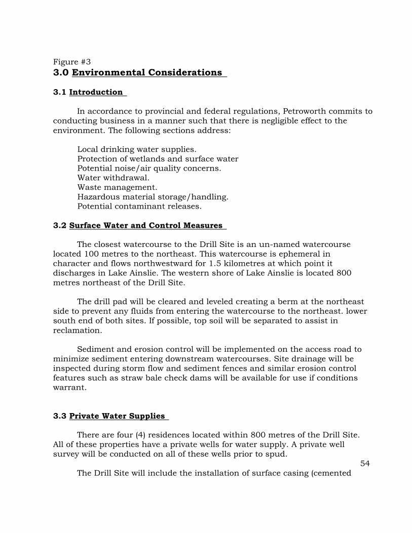
Figure #3
3.0 Environmental Considerations
3.1 Introduction
In accordance to provincial and federal regulations, Petroworth commits to
conducting business in a manner such that there is negligible effect to the
environment. The following sections address:
Local drinking water supplies.
Protection of wetlands and surface water Potential noise/air quality concerns.
Water withdrawal.
Waste management.
Hazardous material storage/handling. Potential contaminant releases.
3.2 Surface Water and Control Measures
The closest watercourse to the Drill Site is an un-named watercourse
located 100 metres to the northeast. This watercourse is ephemeral in
character and flows northwestward for 1.5 kilometres at which point it
discharges in Lake Ainslie. The western shore of Lake Ainslie is located 800
metres northeast of the Drill Site.
The drill pad will be cleared and leveled creating a berm at the northeast
side to prevent any fluids from entering the watercourse to the northeast. lower
south end of both sites. If possible, top soil will be separated to assist in
reclamation.
Sediment and erosion control will be implemented on the access road to
minimize sediment entering downstream watercourses. Site drainage will be
inspected during storm flow and sediment fences and similar erosion control
features such as straw bale check dams will be available for use if conditions
warrant.
3.3 Private Water Supplies
There are four (4) residences located within 800 metres of the Drill Site.
All of these properties have a private wells for water supply. A private well
survey will be conducted on all of these wells prior to spud.
54
The Drill Site will include the installation of surface casing (cemented

back to the surface) to approximately 280 metres which will eliminate or at
least greatly reduce any potential of impacting potable water supplies and/or
local surface water bodies.
3.4 Noise and Air Quality Control
Potential noise problems may occur from the operation of the drilling rig
and support equipment during the drilling of the well. The drilling rig is
equipped with standard noise abatement equipment (mufflers), it is unlikely that
the noise levels will be an issue. In any event, Petroworth will complete a
baseline noise survey Petroworth will also comply with NSEL Guidelines
(Appendix A) which specifies the following limits at the site boundaries.
Water will be sprayed on the access road or construction site if needed
during extensive periods of dry weather. The maximum acceptable dust
concentration 120um/m over 24-hour period will be followed.
3.5 Water Requirements
It is anticipated that approximately 200 m (200,000L) of water will be
required to drill the exploration well (average of 13,500 L per day over the 15 day
period). Petroworth has made arrangements with the local water hauler to provide
these services.
3.6 Waste Generation & Management
Waste management includes miscellaneous garbage generated by field
personal, waste generated from drilling operations; septic/grey water; and, drill
cuttings and fluids. Petroworth will follow the guidance provided in _____
Environmental Best Management Practices for Drilling Wastes including reducing
and reusing materials where possible.
Domestic Waste & IDW
Domestic type waste will be taken to the Kenlock Waste Transfer Station
which is located 5 kilometres north of the drill site. IDW will be properly
contained and disposed of by a qualified contractor.
Septic Waste and Grey Water
Applications for an on-site holding tank to contain septic waste and grey

water have been submitted to the Nova Scotia Department of Environment for
approval. As per the requirements, the applications were prepared by a
Qualified Person (QP) 1 under the Waste Water NS Regulations. Waste will be
transferred off-site for disposal at an acceptable facility.
Drill Cuttings
Petroworth will retain the services of a qualified private contractor to remove
rock cuttings and mud for appropriate off-site disposal. The material will be
sampled for parameters listed in Nova Scotia Department of Environment
Guidelines for Disposal of Contaminated Solids in Landfills. These guidelines
provide acceptable levels for inorganic and organic parameters. If the
concentrations of the specified parameters are exceeded, a leachate extraction
analysis (Canadian General Standards Board (CGSB 164 GP-IMP) is required. If the concentrations of the specified parameters in either of these analysis are less
than or equal to the guidelines, the material is designated as hazardous waste and
is not acceptable a the municipal sold waste landfill. Dewatering to reduce the
volume of material and/or mixture with fly ash, sawdust, cement or some other
substance to help solidify the material and/or reduce the leachability of earth
metals may be warranted.
Drill Fluids
Environmental considerations associated with drilling and gas production
testing are related to water requirements for drilling and disposal of water/liquid
from two sources: 1) water that is introduced during drilling; and, 2) formation
waters generated during testing. Water requirements were discussed under
Section 3.4.
During the drilling, all water will be disposed of at an appropriate offsite
location (qualified contractor). Water quality samples will be collected and
analyzed at a minimum for general chemistry and metals parameters
(particularly chlorides, iron, barium, ammonia and ph). Total Suspended Solids
(TSS) and oxygen demand (COD and BOD). Depending on disposal method
analysis may include toxicity testing. The disposal water for the testing phase has
not yet been determined and will be developed in consultation with Nova Scotia
Department of Environment and their requirements for Onshore Exploration,
Options, such as re-injection etc., will depend on both the quantity and quality of
the water.
Use of filters (to reduce iron concentrations), floating aerators (to provide
oxidation) and setting ponds (to reduce sedimentation levels) will be considered.
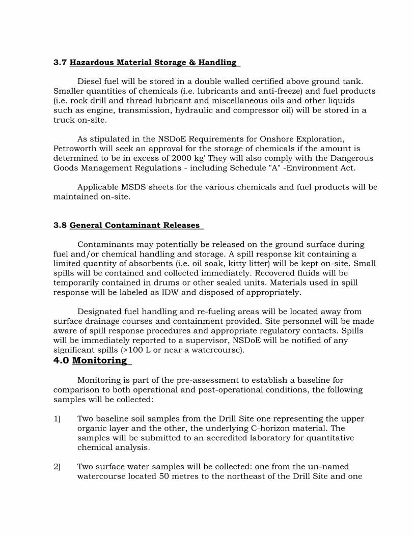
3.7 Hazardous Material Storage & Handling
Diesel fuel will be stored in a double walled certified above ground tank.
Smaller quantities of chemicals (i.e. lubricants and anti-freeze) and fuel products
(i.e. rock drill and thread lubricant and miscellaneous oils and other liquids
such as engine, transmission, hydraulic and compressor oil) will be stored in a
truck on-site.
As stipulated in the NSDoE Requirements for Onshore Exploration,
Petroworth will seek an approval for the storage of chemicals if the amount is
determined to be in excess of 2000 kg' They will also comply with the Dangerous
Goods Management Regulations - including Schedule "A" -Environment Act.
Applicable MSDS sheets for the various chemicals and fuel products will be
maintained on-site.
3.8 General Contaminant Releases
Contaminants may potentially be released on the ground surface during
fuel and/or chemical handling and storage. A spill response kit containing a limited quantity of absorbents (i.e. oil soak, kitty litter) will be kept on-site. Small
spills will be contained and collected immediately. Recovered fluids will be
temporarily contained in drums or other sealed units. Materials used in spill
response will be labeled as IDW and disposed of appropriately.
Designated fuel handling and re-fueling areas will be located away from
surface drainage courses and containment provided. Site personnel will be made
aware of spill response procedures and appropriate regulatory contacts. Spills
will be immediately reported to a supervisor, NSDoE will be notified of any
significant spills (>100 L or near a watercourse).
4.0 Monitoring
Monitoring is part of the pre-assessment to establish a baseline for
comparison to both operational and post-operational conditions, the following
samples will be collected:
1) Two baseline soil samples from the Drill Site one representing the upper
organic layer and the other, the underlying C-horizon material. The
samples will be submitted to an accredited laboratory for quantitative
chemical analysis.
2) Two surface water samples will be collected: one from the un-named
watercourse located 50 metres to the northeast of the Drill Site and one

from the west shore of Lake Ainslie.
5.0 Post-Operations Environmental Components
Post operational activities include, but may not necessarily be limited to the
following:
Disposal of water and fluids associated with drilling and production testing. Disposal of solids associated with drilling
Removal and/or securement of infrastructure.
Collection of post operational samples of comparison of results to baseline.
Post operational report to NSEL addressing environmental aspects if the project.
Reclamation of site as required.
Appendix E
Canadian Petroleum Engineers – Safety And Environmental Plan CANADIAN PETROLEUM ENGINEERING INC.
Safety & Environment Policy
Canadian Petroleum Engineering Inc. is committed to ensuring a safe and healthy workplace and the protection of the environment. We believe that safety and protecting the environment is good business and
that all work related injuries, illnesses, property losses and adverse environmental impacts are
preventable.
To fulfill this commitment, Canadian Petroleum Engineering Inc. will:
Give health, safety and environmental considerations equal status with the Company’s other business
objectives and integrate them into all aspects of its work
Work actively to continuously improve safety and environmental protection Only start work after confirming that essential safety and environmental protection systems are in
place, and willingly suspend operations if safety or the protection of the environment would be compromised
Encourage personnel to be individually responsible for identifying and eliminating hazards, preventing injury to themselves and others, and preventing adverse environmental impacts
Provide personnel with sufficient training, resources and systems

Provide and maintain properly engineered facilities, plants and equipment
Minimize from its activities waste generation, air emissions and other discharges to the environment Actively monitor, audit and review to improve systems, processes, environmental and safety
performances
As a minimum, ensure regulatory compliance at all times Hold contractors and third parties accountable for adhering to Canadian Petroleum Engineering Inc’s
safety and environment policy and audit contractor systems and procedures to ensure satisfactory safety and
environmental protection
Hold supervisory management accountable for ensuring and promoting a safe and healthy workplace and the protection of the environment within their area of responsibility
Responsibility for the application of this policy rests with all employees.
Ed Fercho, President Lorne Hammer, Vice President
Drilling Supervisor’s Responsibilities:
Company Requirements
The Drilling Supervisor is responsible to ensure Contract personnel comply with relevant policies,
guidelines and procedures while working on company property.
Personnel Minimum Training Requirements
Any person directly involved in drilling, completions, workovers and servicing operations
shall have a valid H2S Alive and Standard First Aid or Class “A” certification.
The Site Supervisor shall have valid H2S Alive, First Aid, WHMIS, TDG and B.O.P.
certification with experience of overall rig supervision (drilling, workovers, completions,
recompletions, servicing). Knowledge of the industry recommended practices is required.
• The Rig Manager (Toolpush) shall have valid H2S Alive, First Aid, WHMIS, TDG
and
B.O.P. certification with experience of overall rig supervision (drilling, workovers,
completions, recompletions, servicing). Knowledge of the industry recommended practices is
required.
The Driller shall have valid H2S Alive, First Aid, WHMIS, TDG and B.O.P. certification
with experience as a Driller on drilling and/or service rigs.
The Derrick hand shall have valid H2S Alive, First Aid, WHMIS, TDG and B.O.P.
certification with experience as a Derrick hand on drilling and/or service rigs.
The Floorman shall have valid H2S Alive, First Aid, WHMIS, TDG and B.O.P. certification
with experience as a Floorman on drilling and/or service rigs.
The Safety Supervisor shall have valid H2S Rescue, First Aid, WHMIS, TDG and CPR
certification with three (3) years experience as a Safety Supervisor on drilling and/or service rigs.
Training Verification

The Rig Manager (Toolpush) is responsible to verify the training, qualifications and competency of
the crew prior to work commencement in writing.
Safety Meetings
Safety Meetings are required on all projects to pass on important information to the people doing the
work and to hear the concerns of the workers.
The Drill Supervisor is required to hold a formal, recorded safety meeting for all persons working on
the lease. It may be necessary to hold more than one meeting if crews are working shifts, the
following subjects will be discussed and recorded at this meeting.
General outline of the project and any special safety concerns, i.e. H2S zones, etc.
Emergency procedures and information, i.e. what to do and phone numbers to call if an injury
occurs, etc.
Go over the Material Safety Data Sheets for all hazardous materials on the project and then
post the sheets on the bulletin board (See WHMIS section).
Besides this formal meeting, the crews should be holding their own OH&S safety meetings and
meetings should be held at the beginning of each special job, i.e. running casing, DST, etc. These
meeting should be noted on the morning report.
Joint Hazard Assessments (JHA’s) are to be completed for each specific job conducted and when
operations change or new operations are undertaken.
Environmental Operations Guidelines:
Housekeeping -
The Drilling Supervisor is responsible to ensure:
All drain and bleed valves, capable of releasing system product to the atmosphere, are
plugged or capped when not in use.
Any fitting leaks are repaired as soon as practically possible.
Product spills are contained and cleaned up minimizing environmental damage.
Materials storage is kept clean, neat and orderly.
Flare pit levels are closely monitored and pumped out minimizing product spills and
environmental contamination.
Liquid sample points shall be equipped with a metal container grounded to the system.
Containers shall be emptied after each sampling activity.
Truck Drivers are aware of and responsible for cleaning up any product spill they create.
Costs will be born by the Trucking Company.
Containment dikes are maintained and liquids kept to a minimum.

Sour products are contained in closed systems. System components are monitored for leaks
minimizing release to the environment.
Waste Disposal
The Site Representative is responsible to ensure:
Requirements and restrictions for disposing of waste materials and products in the local
landfill site are available to all personnel.
Filters from engines, glycol and fuel systems shall be placed in a covered container allowing
proper drainage before disposal at an approved facility.
Spilled produced fluids are cleaned up. Under no circumstances shall produced fluids be
disposed of on roads, leases or fields without prior approval in writing from the appropriate
government agency.
Soil, gravel and vegetation contaminated with produced fluids shall be contained and hauled
to a designated area at the facility. Written approval from the appropriate government agency shall
be obtained for appropriate disposal.
Used lubricating oils shall be contained. Under no circumstances shall used lubricating oil be
disposed of on road, leases or fields. Disposal may be injecting the oil into a crude oil process
stream; or written approval shall be obtained from the appropriate government agency for disposal.
Chemical, surplus, out dated, or no longer used in full or partially full containers shall be
stored in a designated area at the facility. Containers shall be sealed. Disposal arrangements shall
be made either with the manufacturer, supplier, or transport by approved couriers to government
approved disposal facilities. Empty containers shall be returned to the supplier, manufacturer, or
transported by approved couriers to government approved disposal facilities.
Uncontaminated daily garbage (paper, food stuff) shall be stored in covered containers to
deter predators. Disposal shall be arranged at the approved landfill site or incinerated.
Emergency Procedures
The Drilling Supervisor shall maintain a current copy of the Corporate Emergency Response Plan at
the location.
At the beginning of all projects the Field Drilling Supervisor will collect and post the following
information:
Location and number of the nearest
Hospital
R.C.M.P.
Ambulance
• office Forestry office in green areas
The nearest helicopter service in remote areas where there may be restricted access due to
road conditions.

These numbers should be posted in the doghouse and/or the project office and/or the
Supervisor’s quarters and at the project camp. All personnel on the project should be made
aware of the numbers and what they should do in an emergency.
In addition to the above numbers, the Supervisor should post a copy of the Drilling
Department “Emergency Contact List” and the Emergency Response Plan flowchart.
In very remote areas, on large projects and on critical wells the above information will be
supplemented with a detailed, site specific emergency response plan.
REPORTING PROCEDURES
1. DAILY DRILLING REPORTS
This report time period is 0000 - 2400 hours.
This report is to be filled out completely and transmitted to the Calgary office by phone and
email by 0730 hours each morning.
All reports are to be submitted to the Calgary office at the completion of the well.
2. CASING AND CEMENTING REPORTS
This report is to be filled out completely after each casing and cement job. It is to be
submitted to the Calgary office at the completion of the well.
Note: The Pipe Tally is to be attached to this report.
3. MATERIAL TRANSFERS
Is to be completed when applicable and submitted to the Calgary office.
4. EVALUATION OF DRILLING/SERVICING OPERATIONS
This report is to be filled out in as much detail as possible (see instructions at top of
form). It is submitted to the Calgary office at the completion of the well.
5. TEST REPORTS
This report is to be filled out after each drillstem / formation test and transmitted to the
Calgary office by phone.
These reports are to be submitted to the Calgary office at the completion of the well.

6. TOUR SHEETS (CAODC DAILY DRILLING REPORT)/WELL DATA
SUMMARY
In addition to the normal information recorded by the Drilling Contractor, the following
information is to be accurately recorded by the wellsite supervisor (in compliance with
governmental regulations):
Casing Details: size, weight, grade, thread, tally, landed depth, float collar depth and
wellhead equipment installed.
Cementing Details: type, amount of dry blend, additives, volumes of cement returns (if
applicable), plug down time, type of fluid used to displace and whether float(s) held.
Pressure Test Details: test pressure and duration for each BOP including manifold.
Leak off Test Details: as well as entering details in tour book, submit form to Nova Scotia
Dept of Energy if required.
BOP Drills: date and time along with comments regarding drill. (Drills to be conducted a
minimum of once per week.)
Drill Stem Test Details: interval, zone, type of test, times, pressures, details of flow and
recovery.
Coring Details: interval, zone, size and recovery.
Logging Details: type and interval.
Abandonment Details: interval, amount and type of cement, top of plug and time felt.
Rig Release Details: date, time and signature.