Petrobras cascade-chinook
92
DEVELOPING THE LOWER TERTIARY WITH THE FIRST FPSO IN THE U.S. GULF OF MEXICO CASCADE AND CHINOOK Supplement to
-
Upload
diego-alonso-junqueira -
Category
Engineering
-
view
172 -
download
15
description
Projeto Exploração Campos Cascade e Chinook
Transcript of Petrobras cascade-chinook
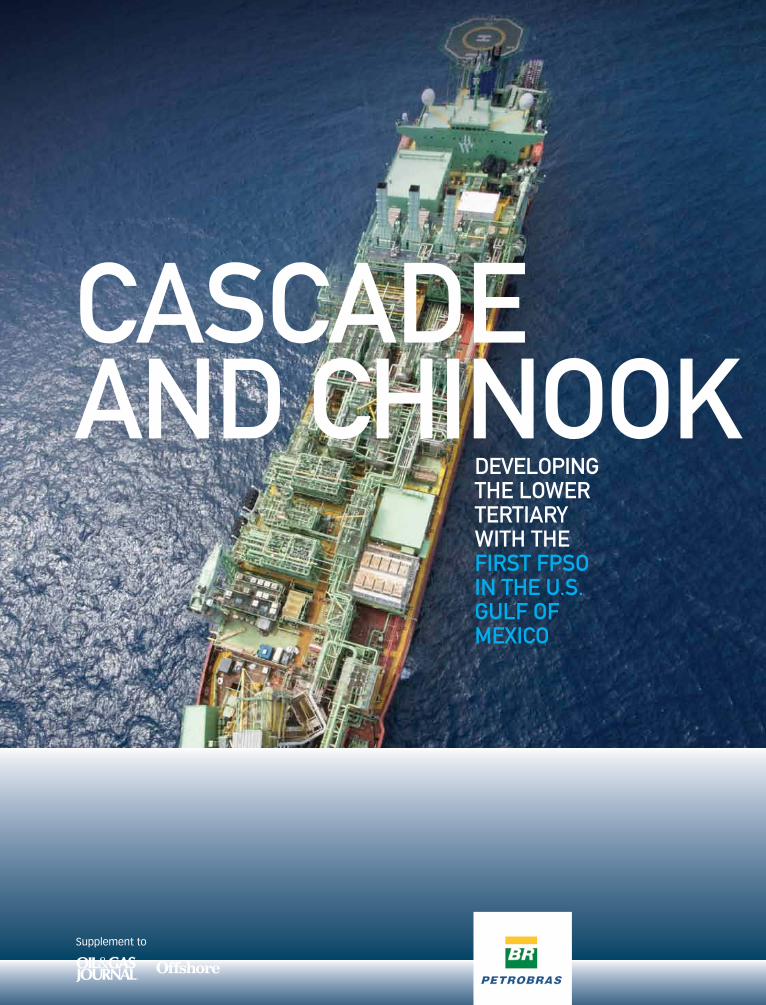
DEVELOPING thE LOwEr tErtIary wIth thE fIrst fPsO IN thE U.s. GULf Of MExIcO
cascaDE aND chINOOk
Supplement to
CustomCustomPublishingPublishing
VP, PennWell Custom Publishing, Roy [email protected]
Project Management – Petrobras America,Braulio Perdigao [email protected]
Managing Editor and Principal Writer,Richard Cunningham [email protected]
Technical Writers, Jerry Greenberg [email protected]
Jay Schempf [email protected]
Contributing Photographers,Chris Miller, Braulio Perdigao, Harald Hohenthal, Jay Olivier, Orlando Ribeiro, Captain Ezra LeBourgeois
Presentation Editor/Designer, Chad [email protected]
Production Manager, Shirley [email protected]: 918.831.9415
cONtENts
Circulation Manager, Tommie [email protected]: 918.831.9722
PennWell Petroleum Group1455 West Loop South, Suite 400Houston, TX 77027 U.S.A.713.621.9720 • fax: 713.963.6285
PennWell Corporate Headquarters1421 S. Sheridan Rd., Tulsa, OK 74112P.C. Lauinger, 1900–1988Chairman, Frank T. LauingerPresident/CEO, Robert F. Biolchini
© 2012 by PennWell Corp.
SponSored by: Supplement to:
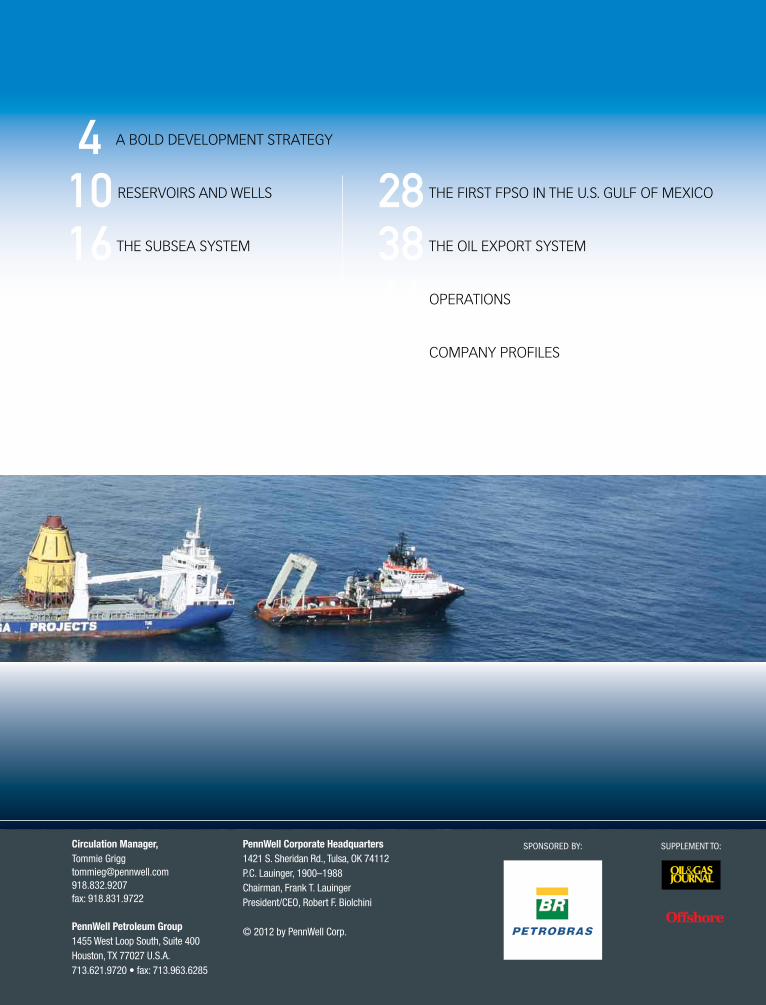
4 A BOLD DEVELOPMENT STRATEGY
10 RESERVOIRS AND WELLS
16 ThE SuBSEA SYSTEM
28 ThE FIRST FPSO IN ThE u.S. GuLF OF MEXICO
38 ThE OIL EXPORT SYSTEM
46 OPERATIONS
54 COMPANY PROFILES
“the cascade and chinook Project put together a great team of men and women, dedicated to improving ultra-deepwater exploration and production technologies to achieve the best possible results. It is a privilege to work with such a talented team.”
Gustavo amaral Upstream senior Vice President, Petrobras america
“without a doubt, cascade and chinook is a pioneering project that brings a new concept in production to the U.s. Gulf of Mexico. the system is in full compliance with U.s. regulations, and in line with Petrobras’ safety, environmental and health guidelines.”
Orlando azevedo President, Petrobras america
“the deepwater drilling and operating experience that Petrobras america brings to the table makes it uniquely suited to develop the cascade and chinook fields. this is very much what we do for a living.”
césar Palagiwalker ridge asset Manager, Petrobras america
“the Bw Pioneer is the first fPsO in the american sector of the Gulf of Mexico. It will also be the first platform in the Gulf to send oil to the coastline by shuttle tanker rather than by pipeline. this system introduces a new regulatory framework and licensing environment specifically developed for the cascade and chinook Project. all these achievements consolidate the expertise of Petrobras as an energy company acknowledged the world over for technological excellence.”
Jorge Zelada chief International Officer, Petrobras
“Petrobras has faced several challenges in the development of the cascade and chinook fields in the Us Gulf of Mexico. those challenges have been overcome with the expertise that has made this company a benchmark in ultra-deepwater technology for the energy industry around the world.”
fernando cunhaExecutive Manager for the americas, africa and Eurasia, Petrobras
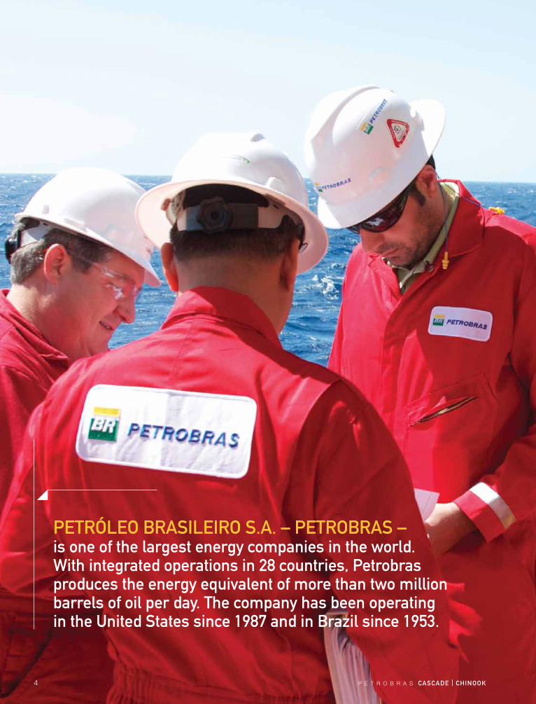
PEtróLEO BrasILEIrO s.a. – PEtrOBras – is one of the largest energy companies in the world. with integrated operations in 28 countries, Petrobras produces the energy equivalent of more than two million barrels of oil per day. the company has been operating in the United states since 1987 and in Brazil since 1953.
4 P E T R O B R A S cascaDE | chINOOk
P E T R O B R A S cascaDE | chINOOk 5
a BOLD DEVELOPMENt stratEGy
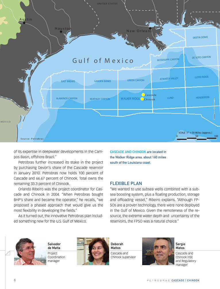
The Cascade and Chinook ultra-deepwater fields are lo-cated in the Walker Ridge area of the u.S. Gulf of Mexico, about 15 miles apart and some 160 miles south of the Louisiana coast. The target zone – largely untested in waters this deep – is in a geologic layer known as the Lower Tertiary.
The Cascade discovery well, drilled in a water depth of 8,143 feet (2,481 meters) found oil in April, 2002. The discovery well for Chinook, drilled in 8,831 feet (2,962 meters) of water, reached total depth in June, 2003. The current and future production wells will all have subsea wellheads.
The resource is being developed by Petrobras and its partner, Total, under a three-phase plan approved by the u.S. Bureau of Ocean Energy Management, Regu-lation and Enforcement (BOEMRE). Petrobras has held working interests in several Walker Ridge blocks since 1996, but when the 10-year leases were about to ex-pire in 2006, Petrobras and its partners had a decision to make: whether to develop the resources or let the leases expire.
“Even though we found oil, it was not an easy deci-sion to continue because of the location of the wells,” says César Palagi, Walker Ridge asset manager for Petrobras America. “They are in an area of the gulf with no infrastructure. The technical difficulties of the project were daunting.”
Three of the original partners, Devon Energy, Petro-bras and Total wanted to continue. Amerada hess and BhP Billiton, which had drilled the discovery wells, want-ed out. Petrobras bought BhP’s share of the lease in Au-gust, 2006.
“Petrobras, Devon and Total decided to stay,” Palagi recalls. “Petrobras was chosen as the operator because
Orlando ribeiro
Cascade and Chinook project coordinator
renato Bertani
Former PAI President
alberto Guimaraes
Former PAI President
Joao figueira
Former PAI upstream VP
6 P E T R O B R A S cascaDE | chINOOk
Au s t in
H ou s tonN ew O r le a n s
UN I T E D S T A T E S
C a s c a d e a n d C h in o o k F i e l d s i n G u l f o f M e x i c o
MEX I CO
S ou r c e : P e t r ob r a s
G u l f o f M e x i c o
HENDERSON
LLOYD RIDGE
ALAMINOS CANYON
EAST BREAKS
KEATHLEY CANYON
GARDEN BANKS
WALKER RIDGE
GREEN CANYON
LUND
ATWATER VALLEY
MISSISSIPPI CANYONDE SOTO CANYON
DESTIN DOME
0 50 100SCALE :1" = 50 Miles (approx. )
Ca s c a de
Ch in ook
of its expertise in deepwater developments in the Cam-pos Basin, offshore Brazil.”
Petrobras further increased its stake in the project by purchasing Devon’s share of the Cascade reservoir in January 2010. Petrobras now holds 100 percent of Cascade and 66.67 percent of Chinook. Total owns the remaining 33.3 percent of Chinook.
Orlando Ribeiro was the project coordinator for Cas-cade and Chinook in 2004. “When Petrobras bought BhP’s share and became the operator,” he recalls, “we proposed a phased approach that would give us the most flexibility in developing the fields.”
As it turned out, the innovative Petrobras plan includ-ed something new for the u.S. Gulf of Mexico.
fLExIBLE PLaN“We wanted to use subsea wells combined with a sub-sea boosting system, plus a floating production, storage and offloading vessel,” Ribeiro explains. “Although FP-SOs are a proven technology, there were none deployed in the Gulf of Mexico. Given the remoteness of the re-source, the extreme water depth and uncertainty of the reservoirs, the FPSO was a natural choice.”
cascaDE aND chINOOk are located in
the walker ridge area, about 160 miles
south of the Louisiana coast.
sergio Matos
Cascade and Chinook hSE and Regulatory manager
Deborah Mattos
Cascade and Chinook supervisor
salvador de Matta
Project Coordination manager
P E T R O B R A S cascaDE | chINOOk 7
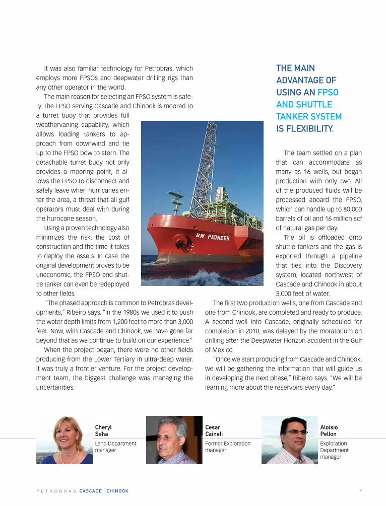
It was also familiar technology for Petrobras, which employs more FPSOs and deepwater drilling rigs than any other operator in the world.
The main reason for selecting an FPSO system is safe-ty. The FPSO serving Cascade and Chinook is moored to a turret buoy that provides full weathervaning capability, which allows loading tankers to ap-proach from downwind and tie up to the FPSO bow to stern. The detachable turret buoy not only provides a mooring point, it al-lows the FPSO to disconnect and safely leave when hurricanes en-ter the area, a threat that all gulf operators must deal with during the hurricane season.
using a proven technology also minimizes the risk, the cost of construction and the time it takes to deploy the assets. In case the original development proves to be uneconomic, the FPSO and shut-tle tanker can even be redeployed to other fields.
“The phased approach is common to Petrobras devel-opments,” Ribeiro says. “In the 1980s we used it to push the water depth limits from 1,200 feet to more than 3,000 feet. Now, with Cascade and Chinook, we have gone far beyond that as we continue to build on our experience.”
When the project began, there were no other fields producing from the Lower Tertiary in ultra-deep water. It was truly a frontier venture. For the project develop-ment team, the biggest challenge was managing the uncertainties.
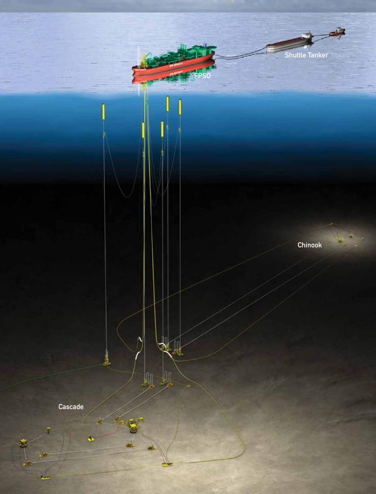
The team settled on a plan that can accommodate as many as 16 wells, but began production with only two. All of the produced fluids will be processed aboard the FPSO, which can handle up to 80,000 barrels of oil and 16 million scf of natural gas per day.
The oil is offloaded onto shuttle tankers and the gas is exported through a pipeline that ties into the Discovery system, located northwest of Cascade and Chinook in about 3,000 feet of water.
The first two production wells, one from Cascade and one from Chinook, are completed and ready to produce. A second well into Cascade, originally scheduled for completion in 2010, was delayed by the moratorium on drilling after the Deepwater horizon accident in the Gulf of Mexico.
“Once we start producing from Cascade and Chinook, we will be gathering the information that will guide us in developing the next phase,” Ribeiro says. “We will be learning more about the reservoirs every day.”
cheryl saha
Land Department manager
thE MaIN aDVaNtaGE Of UsING aN fPsO aND shUttLE taNkEr systEM Is fLExIBILIty.
cesarcaineli
Former Exploration manager
aloisio Pellon
Exploration Department manager
8 P E T R O B R A S cascaDE | chINOOk
fPsO
shuttle tanker
cascade
chinook
P E T R O B R A S cascaDE | chINOOk 9
safELy aDVaNcING thE tEchNOLOGyThroughout the planning phase, the project team ex-tended the boundaries of deepwater technology. Above all, their goal was to do it right.
“We advanced the technology on several components and systems, not because we wanted to, but because there was no alternative,” Palagi says. “We did it in a very responsible way. We kept asking ourselves, is there any-thing that could stop the project if we go this route? The answer I got from the technical guys was always, ‘No’.”
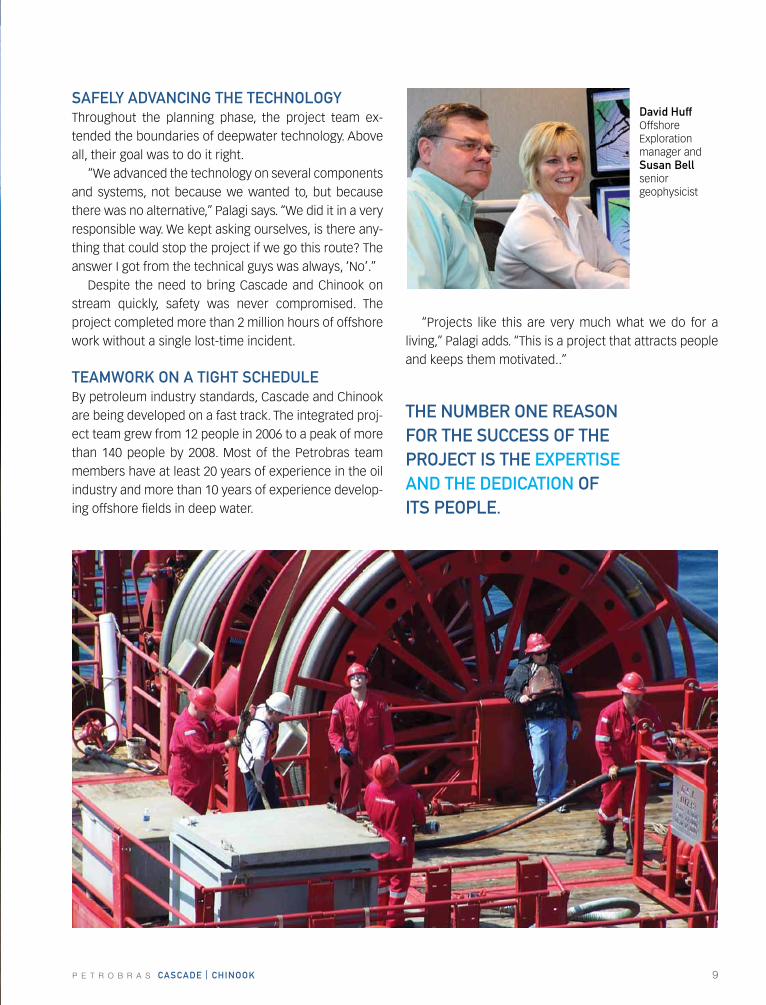
Despite the need to bring Cascade and Chinook on stream quickly, safety was never compromised. The project completed more than 2 million hours of offshore work without a single lost-time incident.
tEaMwOrk ON a tIGht schEDULEBy petroleum industry standards, Cascade and Chinook are being developed on a fast track. The integrated proj-ect team grew from 12 people in 2006 to a peak of more than 140 people by 2008. Most of the Petrobras team members have at least 20 years of experience in the oil industry and more than 10 years of experience develop-ing offshore fields in deep water.
“Projects like this are very much what we do for a living,” Palagi adds. “This is a project that attracts people and keeps them motivated..”
David huff Offshore Exploration manager and susan Bellsenior geophysicist
thE NUMBEr ONE rEasON fOr thE sUccEss Of thE PrOJEct Is thE ExPErtIsE aND thE DEDIcatION Of Its PEOPLE.
10 P E T R O B R A S cascaDE | chINOOk
P E T R O B R A S cascaDE | chINOOk 11
What may turn out to be one of the most significant dis-coveries in the Gulf of Mexico was almost overlooked. The original exploration plan in 2002 was to drill a rela-tively shallow wildcat into what is now the Cascade field, but the main target, the Miocene sands, contained no oil.
Then the partners decided to go deeper. “We still had money in the budget for that well,” says
Julio Syrio, reservoir manager for Cascade and Chinook. “The seismic data showed some interesting structures in a deeper formation, so our geoscientists agreed we should drill deeper than the original plan. Our partners agreed, and in April 2002, we reached a high pressure reservoir sand that could potentially hold a lot of oil, and that became the discovery well for Cascade.”
Chinook, discovered in the following year, was equally promising.
“The two fields are similar,” Syrio explains. “They have the same sands as the Wilcox formation, but they’re not strictly analogs. The main characteristics of these reservoirs are that they are very deep, and the pressures are very high compared to what we normally find at that depth.”
In a well with a true vertical depth (TVD) greater than 27,000 feet (8,230 meters), drillers typically encoun-ter pressures between 11,000 and 12,000 psi. Cascade and Chinook each came in around 19,500 psi. There are many possible reasons for the excess pressure, but the truth may never be known, or at least not until the fields are fully developed and studied. One theory is that the reservoir and adjacent formations acted like a pressure cooker when the oil originally formed, and there was no way for the pressure to escape.
“Such high pressure reservoirs are not unheard of,” Syrio notes, “but normally, they are very small. What’s un-usual here is that the reservoirs are much bigger than we expected, and it looks like they are somehow connected.”
rEsErVOIrs aND wELLs
Julio syrio
Cascade and Chinook reservoir manager
flavio Moraes Cascade and Chinook well engineering manager
sINGLE-trIP MULtI-ZONE (stMZ) completions significantly reduced the costs of the cascade and chinook wells.
ricardo Gomes
Geological Operations manager
Paulo cruz
Reservoir Area manager
12 P E T R O B R A S cascaDE | chINOOk
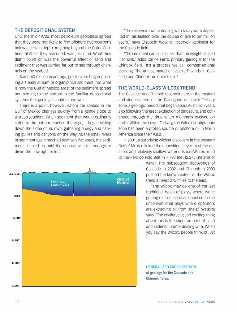
thE DEPOsItIONaL systEM until the mid-1970s, most petroleum geologists agreed that they were not likely to find offshore hydrocarbons below a certain depth. Anything beyond the Outer Con-tinental Shelf, they reasoned, was just mud. What they didn’t count on was the powerful effect of sand and sediment that was carried far out to sea through chan-nels on the seabed.
Some 60 million years ago, great rivers began push-ing a steady stream of organic-rich sediment into what is now the Gulf of Mexico. Most of the sediment spread out, settling to the bottom in the familiar depositional systems that geologists understand well.
There is a point, however, where the seabed in the Gulf of Mexico changes quickly from a gentle slope to a steep gradient. When sediment that would ordinarily settle to the bottom reached the edge, it began sliding down the slope on its own, gathering energy and carv-ing gullies and canyons on the way. As the small rivers of sediment again reached relatively flat areas, the sedi-ment stacked up until the deposit was tall enough to divert the flow right or left.
“The reservoirs we’re dealing with today were depos-ited in this fashion over the course of five to ten million years,” says Elizabeth Watkins, reservoir geologist for the Cascade field.
“The sediment came in so fast that the weight caused it to sink,” adds Carlos Ferro, primary geologist for the Chinook field. “It’s a process we call compensational stacking. The amalgamated or ‘stacked’ sands in Cas-cade and Chinook are quite thick.”
thE wOrLD-cLass wILcOx trENDThe Cascade and Chinook reservoirs are at the eastern and deepest end of the Paleogene or Lower Tertiary zone, a geologic period that began about 65 million years ago following the great extinction of dinosaurs, and con-tinued through the time when mammals evolved on earth. Within the Lower Tertiary, the Wilcox stratigraphic zone has been a prolific source of onshore oil in North America since the 1930s.
In 2001, a surprising wildcat discovery in the western Gulf of Mexico linked the depositional system of the on-shore and relatively shallow-water offshore Wilcox trend to the Perdido Fold Belt in 7,790 feet (2,375 meters) of
water. The subsequent discoveries of Cascade in 2002 and Chinook in 2003 pushed the known extent of the Wilcox trend at least 275 miles to the east.
“The Wilcox may be one of the last traditional types of plays, where we’re getting oil from sand as opposed to the unconventional plays where operators are extracting oil from shale,” Watkins says. “The challenging and exciting thing about this is the sheer amount of sand and sediment we’re dealing with. When you say the Wilcox, people think of just
GENEraLIZED crOss-sEctION
of geology for the cascade and
chinook fields.
P E T R O B R A S cascaDE | chINOOk 13
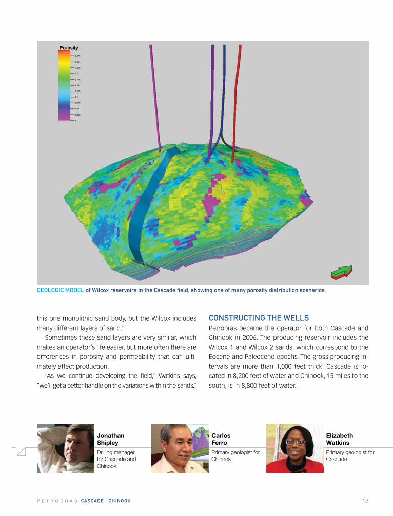
this one monolithic sand body, but the Wilcox includes many different layers of sand.”
Sometimes these sand layers are very similar, which makes an operator’s life easier, but more often there are differences in porosity and permeability that can ulti-mately affect production.
“As we continue developing the field,” Watkins says, “we’ll get a better handle on the variations within the sands.”
cONstrUctING thE wELLsPetrobras became the operator for both Cascade and Chinook in 2006. The producing reservoir includes the Wilcox 1 and Wilcox 2 sands, which correspond to the Eocene and Paleocene epochs. The gross producing in-tervals are more than 1,000 feet thick. Cascade is lo-cated in 8,200 feet of water and Chinook, 15 miles to the south, is in 8,800 feet of water.
Jonathan Shipley
Drilling manager for Cascade and Chinook
Elizabeth Watkins
Primary geologist for Cascade
Carlos Ferro
Primary geologist for Chinook
GEOLOGIc MODEL of wilcox reservoirs in the cascade field, showing one of many porosity distribution scenarios.
14 P E T R O B R A S cascaDE | chINOOk
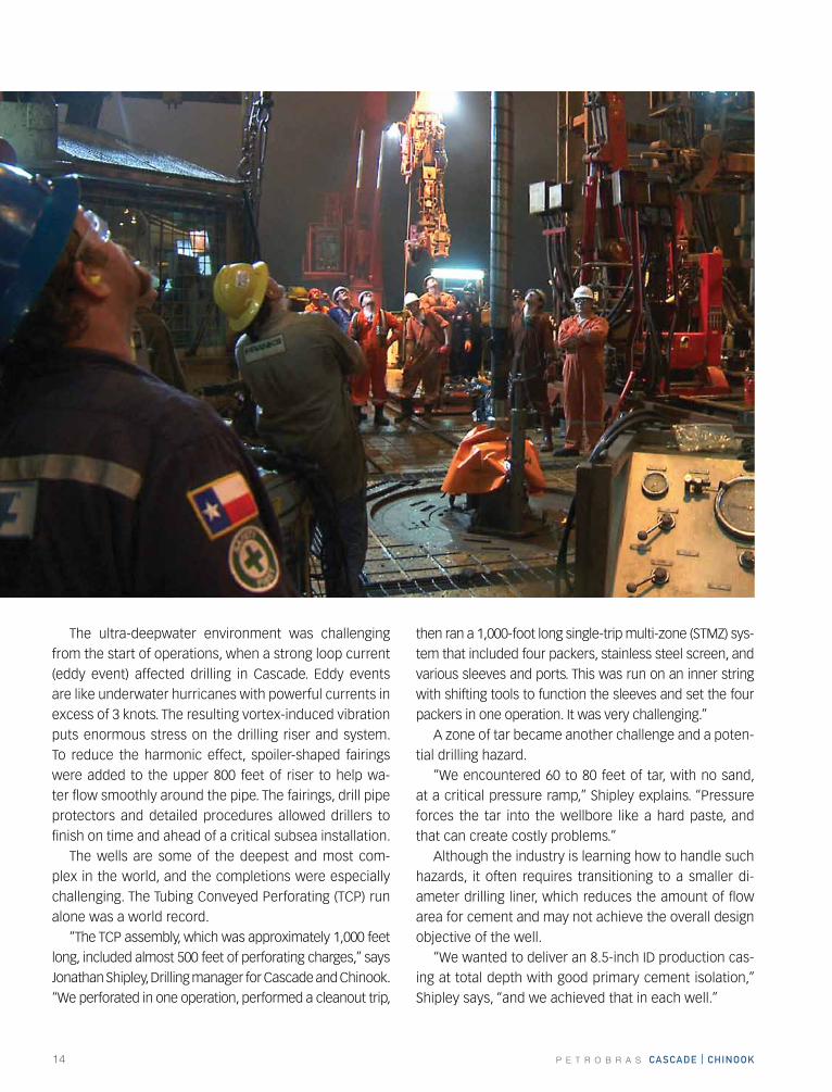
The ultra-deepwater environment was challenging from the start of operations, when a strong loop current (eddy event) affected drilling in Cascade. Eddy events are like underwater hurricanes with powerful currents in excess of 3 knots. The resulting vortex-induced vibration puts enormous stress on the drilling riser and system. To reduce the harmonic effect, spoiler-shaped fairings were added to the upper 800 feet of riser to help wa-ter flow smoothly around the pipe. The fairings, drill pipe protectors and detailed procedures allowed drillers to finish on time and ahead of a critical subsea installation.
The wells are some of the deepest and most com-plex in the world, and the completions were especially challenging. The Tubing Conveyed Perforating (TCP) run alone was a world record.
“The TCP assembly, which was approximately 1,000 feet long, included almost 500 feet of perforating charges,” says Jonathan Shipley, Drilling manager for Cascade and Chinook. “We perforated in one operation, performed a cleanout trip,
then ran a 1,000-foot long single-trip multi-zone (STMZ) sys-tem that included four packers, stainless steel screen, and various sleeves and ports. This was run on an inner string with shifting tools to function the sleeves and set the four packers in one operation. It was very challenging.”
A zone of tar became another challenge and a poten-tial drilling hazard.
“We encountered 60 to 80 feet of tar, with no sand, at a critical pressure ramp,” Shipley explains. “Pressure forces the tar into the wellbore like a hard paste, and that can create costly problems.”
Although the industry is learning how to handle such hazards, it often requires transitioning to a smaller di-ameter drilling liner, which reduces the amount of flow area for cement and may not achieve the overall design objective of the well.
“We wanted to deliver an 8.5-inch ID production cas-ing at total depth with good primary cement isolation,” Shipley says, “and we achieved that in each well.”
P E T R O B R A S cascaDE | chINOOk 15
“The name of the game for a project like this is to be prepared for everything,” says Flavio Moraes, the Cas-cade and Chinook Well Engineering manager. “You plan for the good and the bad. You have plans for mitigating all kinds of anticipated risks. Sometimes we use all the plans: A, B, C and D. You want to get lucky, but there’s too much at stake not to have backup plans.”
A detailed analysis of the in-situ rock stresses, along with numerous runs on a gridded, 3-dimensional fracture simulator, determined the over-all number of intervals. The STMZ technology gave completion engi-neers great flexibility in designing the job and controlling the cost. An STMZ completion also has lower logistical and operational risks, since it requires fewer trips com-pared to traditional deepwater stack-frac systems.
“If your completion design calls for several fractures, then typically you have to repeat that sequence for each stage,” Moraes says. “We
knew that would take too long. The STMZ completions we ran significantly reduced the cost of these wells.”
While single-trip multi-zone technology is commonly used in much shallower wells, it had never been tried at depths much greater than 12,000 feet. At Cascade and Chinook, the wells are twice as deep.
“The treating rate was also greater than anything that had been applied before with this STMZ system,” Moraes says. “That was one of the contributions that this proj-
ect has made, to demonstrate to the industry that single-trip multi-zone frac-pack completions could be done at these depths.”
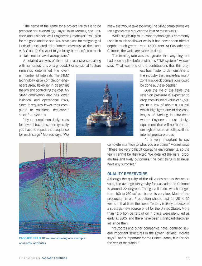
Over the life of the fields, the reservoir pressure is expected to drop from its initial value of 19,500 psi to a low of about 8,000 psi, which highlights one of the chal-lenges of working in ultra-deep water: Engineers must design equipment that will not burst un-der high pressure or collapse if the internal pressure drops.
“It is very important to pay complete attention to what you are doing,” Moraes says. “These are very difficult operating environments, so the team cannot be distracted. We detailed the risks, prob-abilities and likely outcomes. The best thing is to never have any surprises.”
QUaLIty rEsErVOIrsAlthough the quality of the oil varies across the reser-voirs, the average API gravity for Cascade and Chinook is around 22 degrees. The gas/oil ratio, which ranges from 100 to 250 scf per barrel, is very low. Most of the production is oil. Production should last for 25 to 30 years. In that time, the Lower Tertiary is likely to become a strategic new source of oil for the united States. More than 12 billion barrels of oil in place were identified as early as 2005, and there have been significant discover-ies since then.
“Petrobras and other companies have identified sev-eral important structures in the Lower Tertiary,” Moraes says. “That is important for the united States, but also for the rest of the world. ”
cascaDE fIELD 3D volume showing one example
of seismic attributes.
16 P E T R O B R A S cascaDE | chINOOk
P E T R O B R A S cascaDE | chINOOk 17
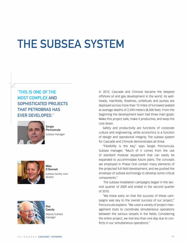
“thIs Is ONE Of thE MOst cOMPLEx aND sOPhIstIcatED PrOJEcts that PEtrOBras has EVEr DEVELOPED.”
In 2012, Cascade and Chinook became the deepest offshore oil and gas development in the world. Its well-heads, manifolds, flowlines, umbilicals and pumps are deployed across more than 12 miles of furrowed seabed at average depths of 2,590 meters (8,500 feet). From the beginning the development team had three main goals: Make this project safe, make it productive, and keep the cost down.
Safety and productivity are functions of corporate culture and engineering, while economics is a function of design and operational integrity. The subsea system for Cascade and Chinook demonstrates all three.
“Flexibility is the key,” says Sergio Porciuncula, Subsea manager. “Much of it comes from the use of standard modular equipment that can easily be expanded to accommodate future plans. The concepts we employed in Phase One contain many elements of the projected full-field development, and we pushed the envelope of subsea technology to develop some critical components.”
The subsea installation campaigns began in the sec-ond quarter of 2009 and ended in the second quarter of 2010.
“We knew early on that the success of these cam-paigns was key to the overall success of our project,” Porciuncula explains. “We used a variety of project man-agement tools to coordinate simultaneous operations between the various vessels in the fields. Considering the entire project, we lost less than one day due to con-flicts in our simultaneous operations.”
thE sUBsEa systEM
sergio Porciuncula
Subsea manager
Mike O’Donnell
Subsea facility coor-dinator
Gus cassity
Deputy Subsea manager
18 P E T R O B R A S cascaDE | chINOOk
kazuhiko kochi
Subsea equipment contract manager
John weigle
Installation contract manager
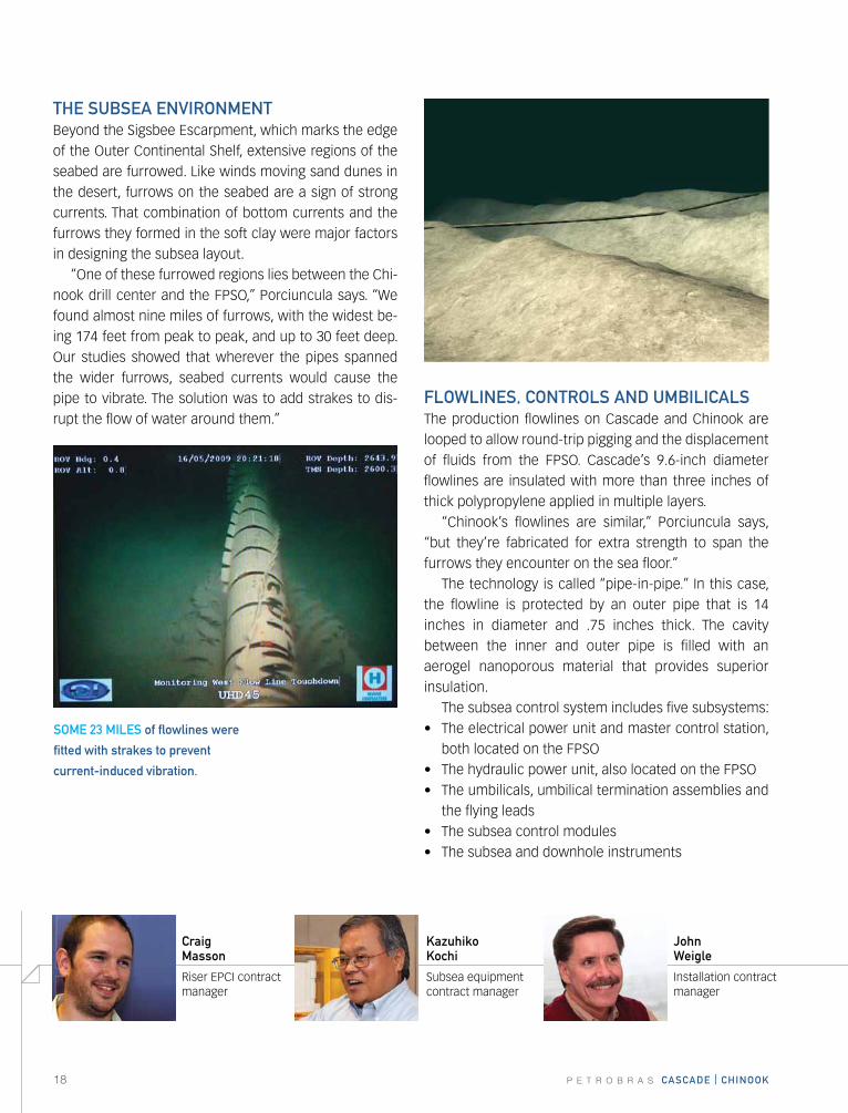
thE sUBsEa ENVIrONMENtBeyond the Sigsbee Escarpment, which marks the edge of the Outer Continental Shelf, extensive regions of the seabed are furrowed. Like winds moving sand dunes in the desert, furrows on the seabed are a sign of strong currents. That combination of bottom currents and the furrows they formed in the soft clay were major factors in designing the subsea layout.
“One of these furrowed regions lies between the Chi-nook drill center and the FPSO,” Porciuncula says. “We found almost nine miles of furrows, with the widest be-ing 174 feet from peak to peak, and up to 30 feet deep. Our studies showed that wherever the pipes spanned the wider furrows, seabed currents would cause the pipe to vibrate. The solution was to add strakes to dis-rupt the flow of water around them.”
fLOwLINEs, cONtrOLs aND UMBILIcaLsThe production flowlines on Cascade and Chinook are looped to allow round-trip pigging and the displacement of fluids from the FPSO. Cascade’s 9.6-inch diameter flowlines are insulated with more than three inches of thick polypropylene applied in multiple layers.
“Chinook’s flowlines are similar,” Porciuncula says, “but they’re fabricated for extra strength to span the furrows they encounter on the sea floor.”
The technology is called “pipe-in-pipe.” In this case, the flowline is protected by an outer pipe that is 14 inches in diameter and .75 inches thick. The cavity between the inner and outer pipe is filled with an aerogel nanoporous material that provides superior insulation.
The subsea control system includes five subsystems:• Theelectricalpowerunitandmastercontrolstation,
both located on the FPSO• Thehydraulicpowerunit,alsolocatedontheFPSO• Theumbilicals,umbilicalterminationassembliesand
the flying leads• Thesubseacontrolmodules• Thesubseaanddownholeinstruments
sOME 23 MILEs of flowlines were
fitted with strakes to prevent
current-induced vibration.
craig Masson
Riser EPCI contract manager
P E T R O B R A S cascaDE | chINOOk 19
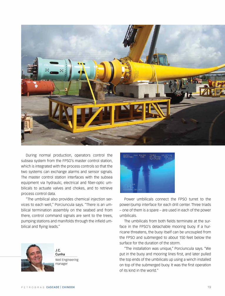
During normal production, operators control the subsea system from the FPSO’s master control station, which is integrated with the process controls so that the two systems can exchange alarms and sensor signals. The master control station interfaces with the subsea equipment via hydraulic, electrical and fiber-optic um-bilicals to actuate valves and chokes, and to retrieve process control data.
“The umbilical also provides chemical injection ser-vices to each well,” Porciuncula says. “There is an um-bilical termination assembly on the seabed and from there, control command signals are sent to the trees, pumping stations and manifolds through the infield um-bilical and flying leads.”
Power umbilicals connect the FPSO turret to the power/pump interface for each drill center. Three triads – one of them is a spare – are used in each of the power umbilicals.
The umbilicals from both fields terminate at the sur-face in the FPSO’s detachable mooring buoy. If a hur-ricane threatens, the buoy itself can be uncoupled from the FPSO and submerged to about 150 feet below the surface for the duration of the storm.
“The installation was unique,” Porciuncula says. “We put in the buoy and mooring lines first, and later pulled the top ends of the umbilicals up using a winch installed on top of the submerged buoy. It was the first operation of its kind in the world.”
J.c. cunha
Well Engineering manager
20 P E T R O B R A S cascaDE | chINOOk
P E T R O B R A S cascaDE | chINOOk 21
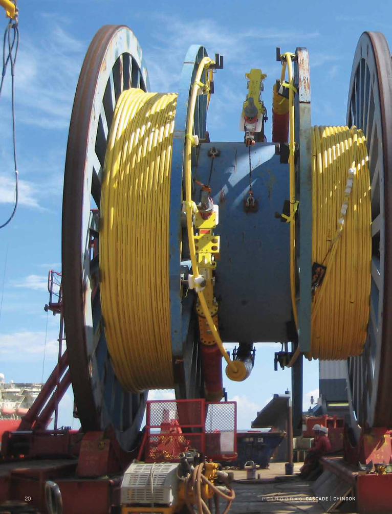
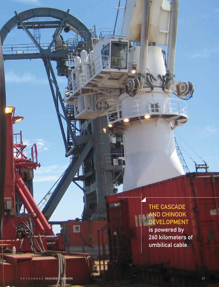
thE cascaDE aND chINOOk DEVELOPMENt is powered by 260 kilometers of umbilical cable.
22 P E T R O B R A S cascaDE | chINOOk
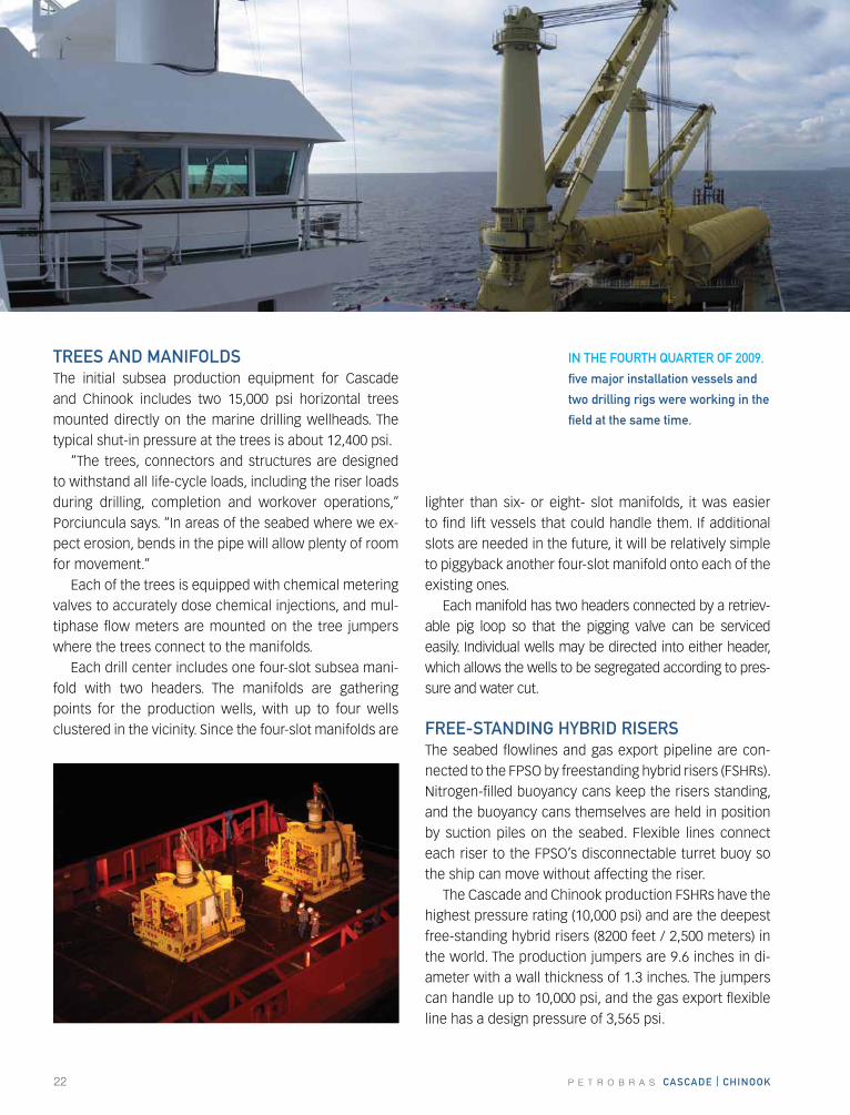
trEEs aND MaNIfOLDs The initial subsea production equipment for Cascade and Chinook includes two 15,000 psi horizontal trees mounted directly on the marine drilling wellheads. The typical shut-in pressure at the trees is about 12,400 psi.
“The trees, connectors and structures are designed to withstand all life-cycle loads, including the riser loads during drilling, completion and workover operations,” Porciuncula says. “In areas of the seabed where we ex-pect erosion, bends in the pipe will allow plenty of room for movement.”
Each of the trees is equipped with chemical metering valves to accurately dose chemical injections, and mul-tiphase flow meters are mounted on the tree jumpers where the trees connect to the manifolds.
Each drill center includes one four-slot subsea mani-fold with two headers. The manifolds are gathering points for the production wells, with up to four wells clustered in the vicinity. Since the four-slot manifolds are
lighter than six- or eight- slot manifolds, it was easier to find lift vessels that could handle them. If additional slots are needed in the future, it will be relatively simple to piggyback another four-slot manifold onto each of the existing ones.
Each manifold has two headers connected by a retriev-able pig loop so that the pigging valve can be serviced easily. Individual wells may be directed into either header, which allows the wells to be segregated according to pres-sure and water cut.
frEE-staNDING hyBrID rIsErsThe seabed flowlines and gas export pipeline are con-nected to the FPSO by freestanding hybrid risers (FShRs). Nitrogen-filled buoyancy cans keep the risers standing, and the buoyancy cans themselves are held in position by suction piles on the seabed. Flexible lines connect each riser to the FPSO’s disconnectable turret buoy so the ship can move without affecting the riser.
The Cascade and Chinook production FShRs have the highest pressure rating (10,000 psi) and are the deepest free-standing hybrid risers (8200 feet / 2,500 meters) in the world. The production jumpers are 9.6 inches in di-ameter with a wall thickness of 1.3 inches. The jumpers can handle up to 10,000 psi, and the gas export flexible line has a design pressure of 3,565 psi.
IN thE fOUrth QUartEr Of 2009,
five major installation vessels and
two drilling rigs were working in the
field at the same time.
P E T R O B R A S cascaDE | chINOOk 23
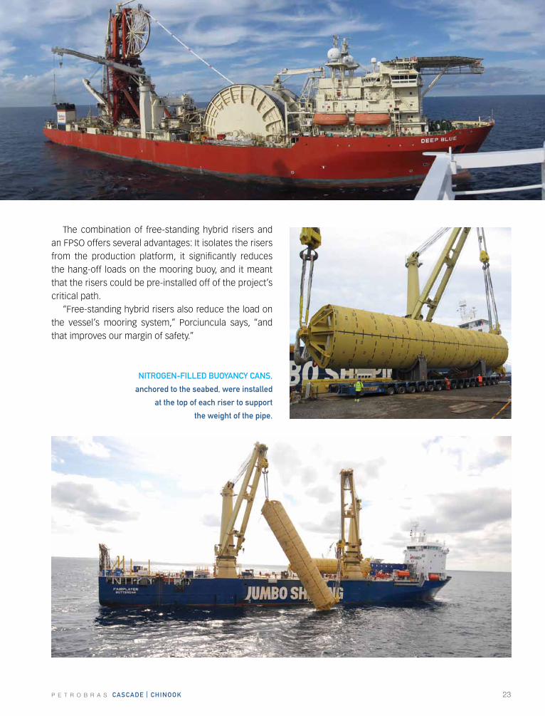
The combination of free-standing hybrid risers and an FPSO offers several advantages: It isolates the risers from the production platform, it significantly reduces the hang-off loads on the mooring buoy, and it meant that the risers could be pre-installed off of the project’s critical path.
“Free-standing hybrid risers also reduce the load on the vessel’s mooring system,” Porciuncula says, “and that improves our margin of safety.”
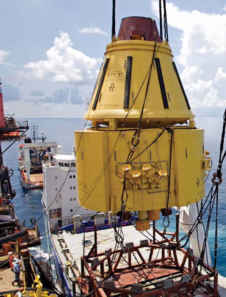
NItrOGEN-fILLED BUOyaNcy caNs,
anchored to the seabed, were installed
at the top of each riser to support
the weight of the pipe.
24 P E T R O B R A S cascaDE | chINOOk
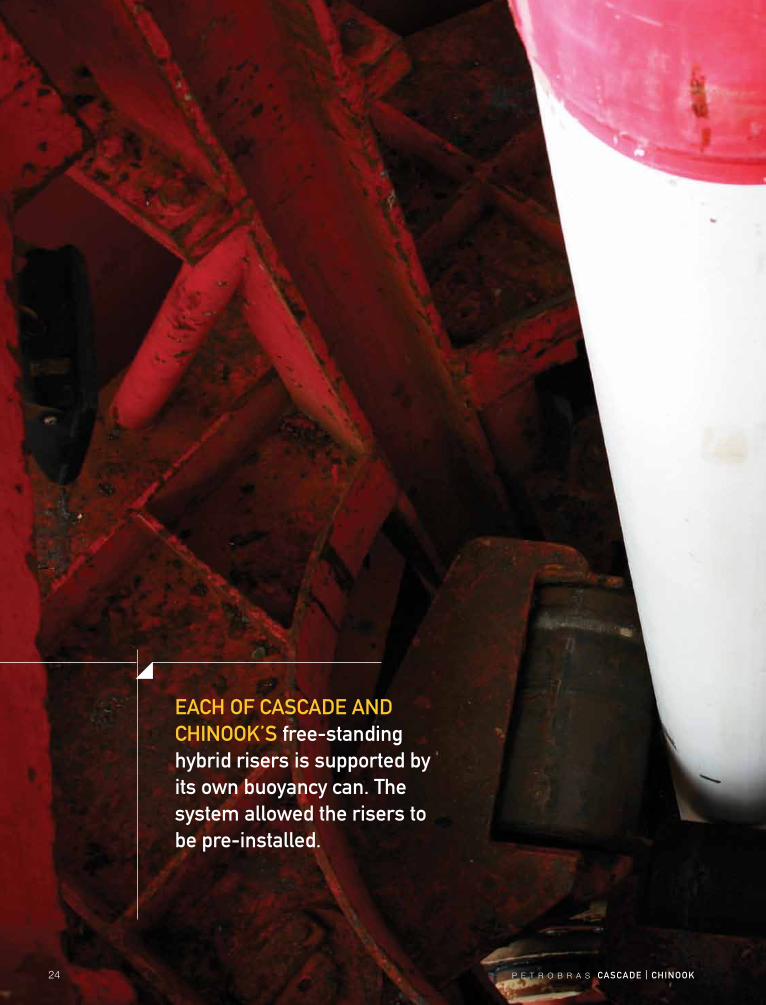
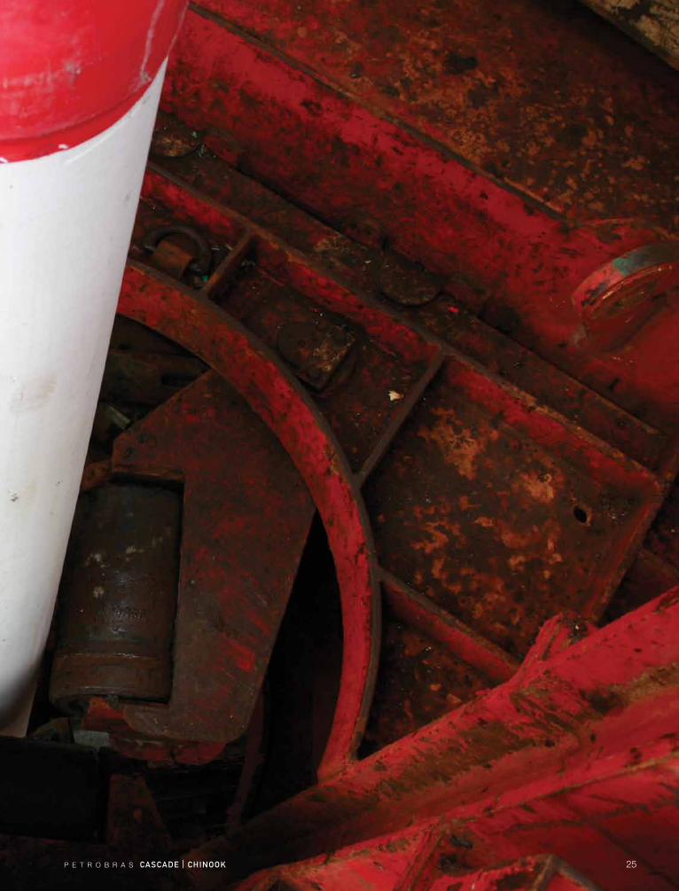
Each Of cascaDE aND chINOOk’s free-standing hybrid risers is supported by its own buoyancy can. the system allowed the risers to be pre-installed.
P E T R O B R A S cascaDE | chINOOk 25
26 P E T R O B R A S cascaDE | chINOOk
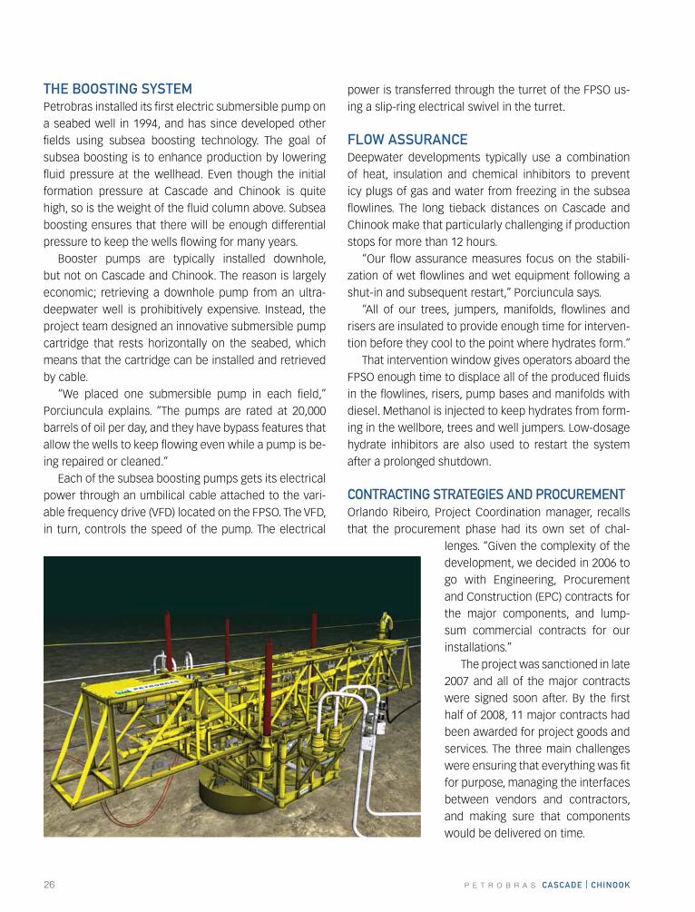
thE BOOstING systEM Petrobras installed its first electric submersible pump on a seabed well in 1994, and has since developed other fields using subsea boosting technology. The goal of subsea boosting is to enhance production by lowering fluid pressure at the wellhead. Even though the initial formation pressure at Cascade and Chinook is quite high, so is the weight of the fluid column above. Subsea boosting ensures that there will be enough differential pressure to keep the wells flowing for many years.
Booster pumps are typically installed downhole, but not on Cascade and Chinook. The reason is largely economic; retrieving a downhole pump from an ultra-deepwater well is prohibitively expensive. Instead, the project team designed an innovative submersible pump cartridge that rests horizontally on the seabed, which means that the cartridge can be installed and retrieved by cable.
“We placed one submersible pump in each field,” Porciuncula explains. “The pumps are rated at 20,000 barrels of oil per day, and they have bypass features that allow the wells to keep flowing even while a pump is be-ing repaired or cleaned.”
Each of the subsea boosting pumps gets its electrical power through an umbilical cable attached to the vari-able frequency drive (VFD) located on the FPSO. The VFD, in turn, controls the speed of the pump. The electrical
power is transferred through the turret of the FPSO us-ing a slip-ring electrical swivel in the turret.
fLOw assUraNcEDeepwater developments typically use a combination of heat, insulation and chemical inhibitors to prevent icy plugs of gas and water from freezing in the subsea flowlines. The long tieback distances on Cascade and Chinook make that particularly challenging if production stops for more than 12 hours.
“Our flow assurance measures focus on the stabili-zation of wet flowlines and wet equipment following a shut-in and subsequent restart,” Porciuncula says.
“All of our trees, jumpers, manifolds, flowlines and risers are insulated to provide enough time for interven-tion before they cool to the point where hydrates form.”
That intervention window gives operators aboard the FPSO enough time to displace all of the produced fluids in the flowlines, risers, pump bases and manifolds with diesel. Methanol is injected to keep hydrates from form-ing in the wellbore, trees and well jumpers. Low-dosage hydrate inhibitors are also used to restart the system after a prolonged shutdown.
cONtractING stratEGIEs aND PrOcUrEMENtOrlando Ribeiro, Project Coordination manager, recalls that the procurement phase had its own set of chal-
lenges. “Given the complexity of the development, we decided in 2006 to go with Engineering, Procurement and Construction (EPC) contracts for the major components, and lump-sum commercial contracts for our installations.”
The project was sanctioned in late 2007 and all of the major contracts were signed soon after. By the first half of 2008, 11 major contracts had been awarded for project goods and services. The three main challenges were ensuring that everything was fit for purpose, managing the interfaces between vendors and contractors, and making sure that components would be delivered on time.

P E T R O B R A S cascaDE | chINOOk 27
“We also limited the number of potential providers,” Ribeiro says. “We stuck with world-class contractors and gave them the responsibility for product and pro-cess development. That freed our project team to con-centrate on hSE, cost, schedules, interface controls and quality management.”
Major components were manufactured in 21 coun-tries and Petrobras was on site to monitor the work. “You get what you inspect, not what you expect,” Ribeiro says, “that was our motto. It must have worked, because all of the equipment and installations were on time and within budget.”
“Some of the technology was completely new,” Por-ciuncula adds. “Electrical connectors for the boosting pumps, for example. There was nothing on the market that could handle the pressures we were dealing with at that water depth.”
Even the power umbilicals were a new design. By mak-ing them larger than anything else on the market – they are almost eight inches in diameter – the project team
was able to deliver high-voltage electrical power some 12 miles across the seabed without using transformers.
a GOOD tEaMWhen Porciuncula joined the project in 2007, the sub-sea team consisted of himself and four others. In two months he hired 50 people.
“Because this is an interesting project, I could get some of the best professionals in the united States,” he says. “A lot of people wanted to be part of this project, but even with good planning there are always surprises. If you don’t have a good team to overcome those sur-prises, you’re in trouble.”
The difference between success and failure is to work very hard and try to anticipate and mitigate all the risks.
“I am very proud of the subsea part of this project,” Porciuncula says. “In spite of all the complexity, we kept on budget and on schedule as it was planned in 2006. We matched our budget 97 percent. As a project man-ager, I think that is the best result I ever had.”
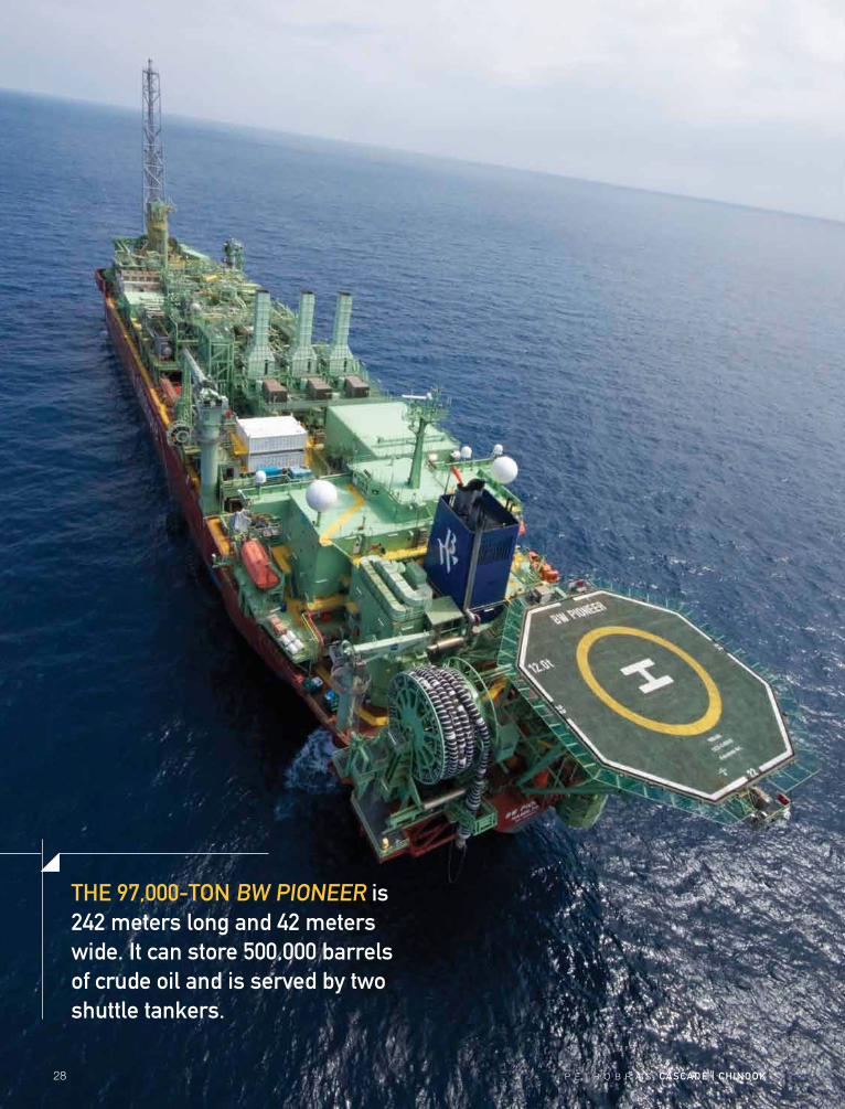
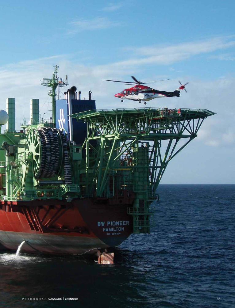
thE 97,000-tON Bw PIONEEr is 242 meters long and 42 meters wide. It can store 500,000 barrels of crude oil and is served by two shuttle tankers.
28 P E T R O B R A S cascaDE | chINOOk
P E T R O B R A S cascaDE | chINOOk 29
“whILE fLOatING PrODUctION, stOraGE aND OffLOaDING systEMs arE cOMMON IN OthEr Parts Of thE wOrLD, wE arE PrOUD tO BrING thE fIrst fPsO tO thE U.s. GULf Of MExIcO.”
When Petrobras began managing the Cascade and Chi-nook development project in late 2004, Antonio Corte and Orlando Ribeiro were in charge. They were, in fact, the whole team. One of their first discussions was how to best develop the fields.
“We explored several ideas and decided that an early production system (EPS) using a disconnectable Floating Production, Storage and Offloading (FPSO) vessel was the best approach,” says Corte, who is the EPS Project and Operations manager for the Walker Ridge asset. “We looked around the world to find other projects similar to ours, searching for vessels that were available for a short-term lease.”
At the same time, Corte and Ribeiro began building the team of drilling, reservoir, subsea, logistics and oth-er specialists they would need to move forward. César Palagi became the Walker Ridge asset manager in 2005 and Ribeiro was named project coordinator.
“We spent all of 2006 on a feasibility study,” Corte says. “In 2007 we asked for bids and by October of that year, we awarded the contract to build the FPSO.”
acQUIrING thE fPsORather than building the FPSO from scratch, the project team decided it would be faster and more economical to refurbish an existing vessel, so that became part of the criteria. Bidders had to identify the ship they would use for the hull, and the contractors they’d hire to con-vert the vessel to an FPSO.
“We signed a contract with BW Offshore in October, 2007,” Corte says. “The ship that BW found was a double-hulled tanker working between u.S. and Caribbean ports.”
thE fIrst fPsO IN thE U.s. GULf Of MExIcO
antonio corte
Cascade and Chinook FPSO Project and Operations manager
Bryan hartman
FPSO project manager
John hensley
hSE Area manager

30 P E T R O B R A S cascaDE | chINOOk
The conversion process began by sending the hull to China, where all of the deck steel was replaced and the decks reinforced to handle the weight of the production equipment that would be added later. The ballast and cargo tanks were not changed.
“We finished in China, and then in September, 2008 we moved the vessel to the Keppel Shipyard in Singapore,” Corte says. “We refurbished the original living quarters and added a second deck to accommodate additional crew, but the largest portion of the work was adding all of the oil and gas production modules and the turret sys-tem. As you can imagine, logistics was a big issue.”
Most of the topsides modules were built in Singapore. Some of the work to finish the vessel, however, was completed at sea during the two-month voyage from Singapore to the South Louisiana coast. After stopping for a crew change in Cape Town, South Africa and again to pick up equipment in Barbados, the FPSO arrived off South Louisiana on March 28, 2010.
The FPSO, now Bermuda-flagged and named the BW Pioneer, is 242 meters long and 42 meters wide. It can process up to 80,000 barrels of produced fluids and 16 million standard cubic feet of natural gas per day, and store 500,000 barrels of oil.
tUrrEt BUOy MOOrING systEMOne of the critical safety features of the early produc-tion system is the FPSO’s Turret Buoy Mooring System (TBMS), which allows the vessel to disconnect from the risers and leave the area in case of a storm.
During normal operations, the turret buoy is the point where produced fluids from the wells board the FPSO. It is moored in 8,200 feet of water by a system of wire, poly-ester and chain mooring lines attached to suction piles.
The system’s turret design allows the FPSO to weather-vane around the buoy, so that the stern is always down-wind. Since shuttle tankers offloading from the FPSO at-tach bow-to-stern, they also remain downwind.
The buoy itself includes two primary structures: the geostationary buoyancy cone and the turret, which can rotate. The buoyancy cone latches into the FPSO’s hull and contains upper and lower mating rings. The upper ring interfaces with the buoy’s latching mechanism, which supports the buoy and related loads while the buoy is connected.
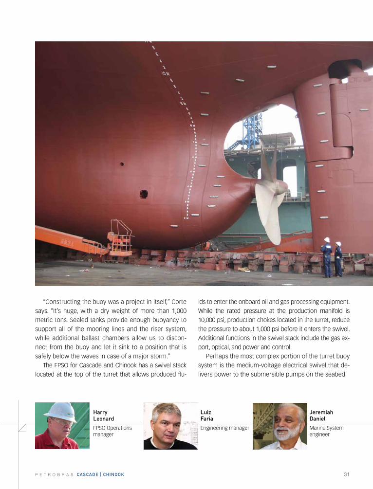
BEfOrE cONVErsION the fPsO
served as an oil tanker.
P E T R O B R A S cascaDE | chINOOk 31
“Constructing the buoy was a project in itself,” Corte says. “It’s huge, with a dry weight of more than 1,000 metric tons. Sealed tanks provide enough buoyancy to support all of the mooring lines and the riser system, while additional ballast chambers allow us to discon-nect from the buoy and let it sink to a position that is safely below the waves in case of a major storm.”
The FPSO for Cascade and Chinook has a swivel stack located at the top of the turret that allows produced flu-
ids to enter the onboard oil and gas processing equipment. While the rated pressure at the production manifold is 10,000 psi, production chokes located in the turret, reduce the pressure to about 1,000 psi before it enters the swivel. Additional functions in the swivel stack include the gas ex-port, optical, and power and control.
Perhaps the most complex portion of the turret buoy system is the medium-voltage electrical swivel that de-livers power to the submersible pumps on the seabed.
Jeremiah Daniel
Marine System engineer
harry Leonard
FPSO Operations manager
Luiz faria
Engineering manager
32 P E T R O B R A S cascaDE | chINOOk
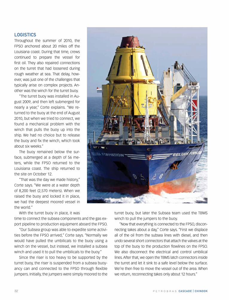
LOGIstIcsThroughout the summer of 2010, the FPSO anchored about 20 miles off the Louisiana coast. During that time, crews continued to prepare the vessel for first oil. They also repaired connections on the turret that had loosened during rough weather at sea. That delay, how-ever, was just one of the challenges that typically arise on complex projects. An-other was the winch for the turret buoy.
“The turret buoy was installed in Au-gust 2009, and then left submerged for nearly a year,” Corte explains. “We re-turned to the buoy at the end of August 2010, but when we tried to connect, we found a mechanical problem with the winch that pulls the buoy up into the ship. We had no choice but to release the buoy and fix the winch, which took about six weeks.”
The buoy remained below the sur-face, submerged at a depth of 56 me-ters, while the FPSO returned to the Louisiana coast. The ship returned to the site on October 12.
“That was the day we made history,” Corte says. “We were at a water depth of 8,200 feet (2,570 meters). When we raised the buoy and locked it in place, we had the deepest moored vessel in the world.”
With the turret buoy in place, it was time to connect the subsea components and the gas ex-port pipeline to production equipment aboard the FPSO.
“Our Subsea group was able to expedite some activi-ties before the FPSO arrived,” Corte says. “Normally we would have pulled the umbilicals to the buoy using a winch on the vessel, but instead, we installed a subsea winch and used it to pull the umbilicals to the buoy.”
Since the riser is too heavy to be supported by the turret buoy, the riser is suspended from a subsea buoy-ancy can and connected to the FPSO through flexible jumpers. Initially, the jumpers were simply moored to the
turret buoy, but later the Subsea team used the TBMS winch to pull the jumpers to the buoy.
“Now that everything is connected to the FPSO, discon-necting takes about a day,” Corte says. “First we displace all of the oil from the subsea lines with diesel, and then undo several short connectors that attach the valves at the top of the buoy to the production flowlines on the FPSO. We also disconnect the electrical and control umbilical lines. After that, we open the TBMS latch connectors inside the turret and let it sink to a safe level below the surface. We’re then free to move the vessel out of the area. When we return, reconnecting takes only about 12 hours.”
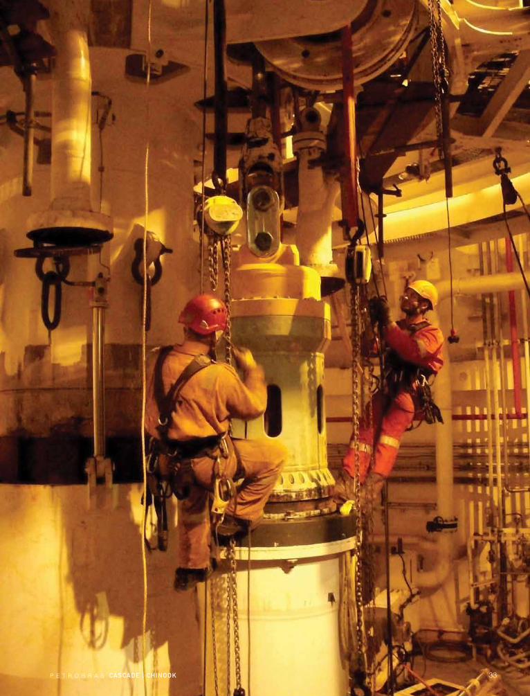
P E T R O B R A S cascaDE | chINOOk 33
34 P E T R O B R A S cascaDE | chINOOk
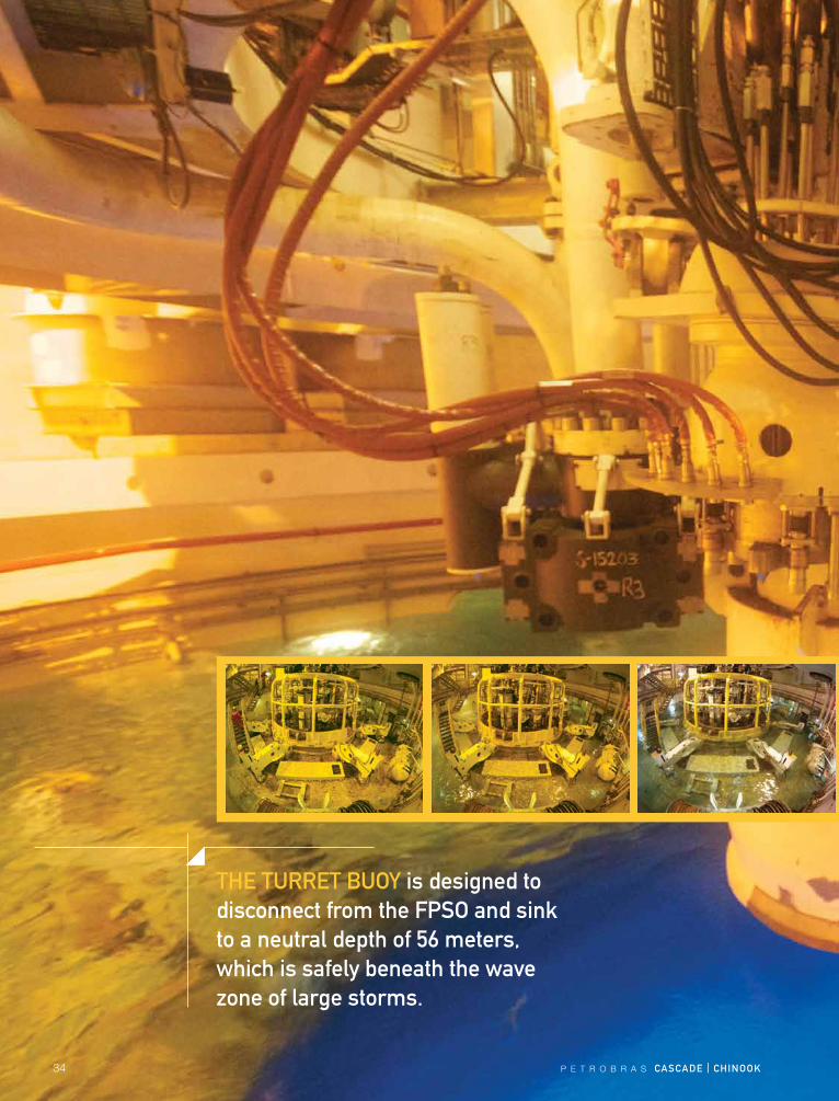
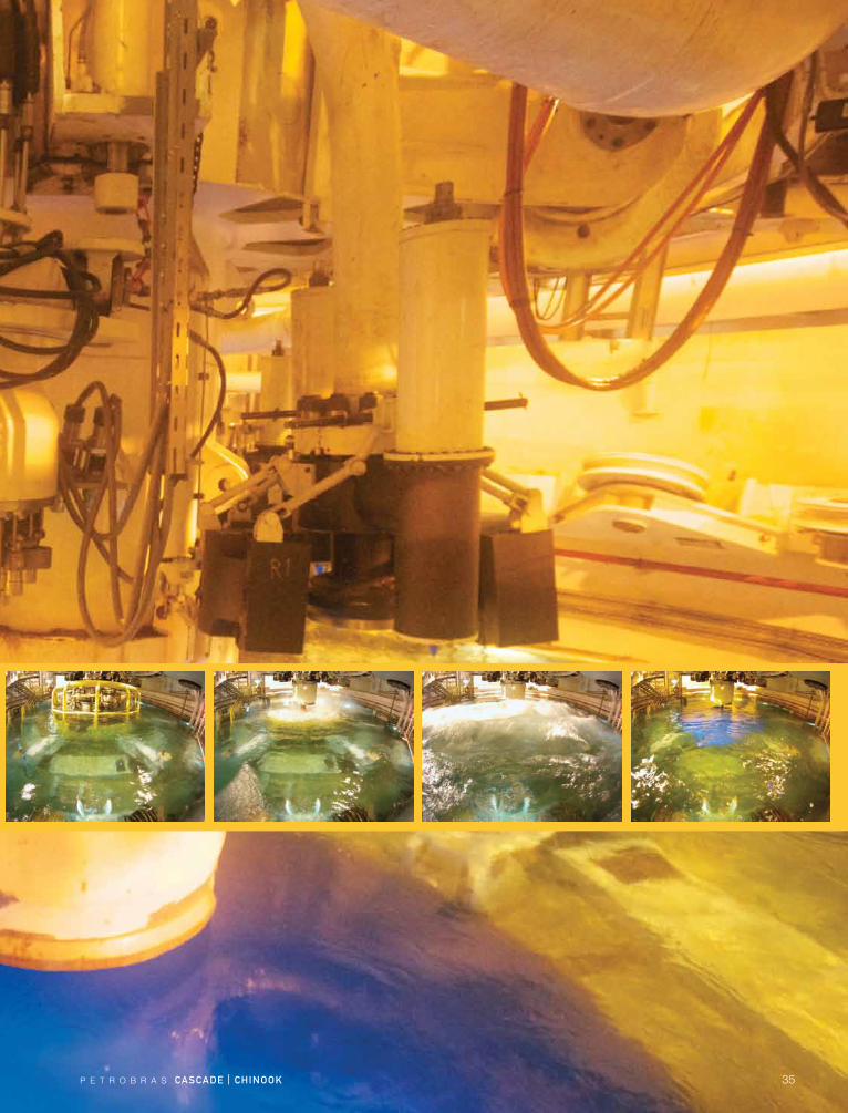
thE tUrrEt BUOy is designed to disconnect from the fPsO and sink to a neutral depth of 56 meters, which is safely beneath the wave zone of large storms.
P E T R O B R A S cascaDE | chINOOk 35

36 P E T R O B R A S cascaDE | chINOOk
NEw OPtIONs IN thE U.s. GULf Of MExIcOThe Minerals Management Service (now the Bureau of Ocean Energy Management, Regulation and Enforce-ment) gave operators the green light to use FPSOs in the u.S. Gulf of Mexico in 2001. Five years later, Petrobras became the first operator to implement a project in the gulf using an FPSO.
Petrobras saw it as an opportunity to draw on its own experience and the industry’s best practices to help de-velop comprehensive regulations that would guide and ensure safe FPSO operations in the Gulf of Mexico for decades to come. The concep-tual plan was approved by the MMS at the end of 2006 and was followed by a two-year pe-riod of close consultation with the MMS and u.S. Coast Guard.
One consideration was a law known as the Jones Act. This segment of the Merchant Marine Act of 1920 requires that all goods transported over water from one u.S. port to another must be carried in u.S.-flagged ships that are built in the united States. While the Jones Act did not apply to the FPSO, it did impact the choice of the shuttle tankers that serve the FPSO.
“An FPSO connected to the seabed in the Gulf of Mexico is considered a u.S. port,” ex-plains Sergio Matos, Petrobras hSE and Regulatory manager. “It means that if you want to transport oil from an FPSO to another u.S. port, the Jones Act requires that the shuttle tanker must be u.S. built and flagged. That is the limitation.”
rEGULatOry fraMEwOrkAlthough the MMS had approved the concept of deploy-ing an FPSO in the Gulf of Mexico, there were few regula-tory guidelines. The rules that were in place dealt mainly with fixed and floating offshore platforms, but when the
Cascade and Chinook development began, there was not a similar set of rules for FPSOs.
“We worked closely with the u.S. Coast Guard, the Minerals Management Service and later, with the Bureau of Ocean Energy Management,” Matos says. “The sup-port of those agencies was key to navigating the over-lapping jurisdictions in uncharted FPSO waters.”
The MMS focused mainly on the oil processing, oil production, and facilities safety aspects of FPSOs, while the Coast Guard made sure that the FPSO met all the marine safety requirements.
“Those interfaces are not easy, because you have sys-tems that are common to both,” Matos says. “Power gen-eration, for example, applies to both. That’s one point where maritime industry standards meet the standards of the off-shore industry.”
The challenge was getting all the technical standards to work together, so that when something met an offshore production standard, it also met the requirements for ma-rine service.
The Conceptual Plan was approved by MMS at the end of 2006 and the back-and-forth process of consultation with the MMS and uSCG took about a year, from 2006 to 2007.
“After that, we spent extra time fine-tuning the regulatory requirements,” Matos adds.
“This was the first project that tested the 2008 Memo-randum of Agreement (MOA) between the two agen-cies for a ship-shaped hull. The MOA was written with the best of intentions, but when you put it to work, you find that particular systems fall under both the uSCG and the MMS jurisdictions, sometimes with conflicting requirements. It was a big learning curve, and I hope the next operator who brings an FPSO into the gulf can ride on that curve.”
P E T R O B R A S cascaDE | chINOOk 37
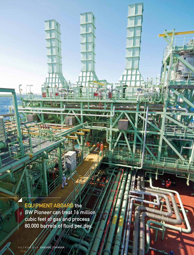
EQUIPMENt aBOarD the Bw Pioneer can treat 16 million cubic feet of gas and process 80,000 barrels of fluid per day.
38 P E T R O B R A S cascaDE | chINOOk
P E T R O B R A S cascaDE | chINOOk 39
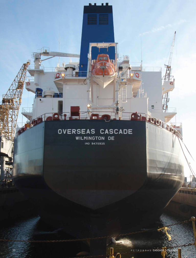
IN 2010, the Overseas cascade became the first purpose-built oil shuttle tanker in the United states.
Deepwater projects around the world often face the same problem: Once you get hydrocarbons out of the reservoir, how do you get them to shore? The Cascade and Chinook development is far from the nearest oil pipeline, and building a new one just to service the proj-ect’s early production system would have been risky and expensive. Shuttle tankers were the safest, most reliable choice, so the contracts to build them were the first to be signed.
“Shuttle tankers, compared to pipelines, also have the advantage of being able to deliver to a variety of customers,” says Carlos Mastrangelo, Facilities manager for Cascade and Chinook. “In Brazil, they are the princi-pal way to transport oil from the country’s vast offshore fields. We average two shuttle tanker operations per day in the Campos Basin.”
Duplicating the system in the Gulf of Mexico would have been relatively easy, except for a u.S. law known as the Jones Act. It requires that any tanker making de-liveries from one u.S. port to another must be built in the united States, and owned and operated primarily by u.S. citizens. Beyond that, Petrobras had its own speci-fications. Finding just one ship that met all the require-ments was nearly impossible. For this project, Petrobras needed two.
“Ours are the first purpose-built Jones Act shuttle tankers in the united States,” Mastrangelo says. “The challenge was that only a few u.S. shipyards could con-struct the vessels to our technical specifications and meet or surpass u.S. regulations, and it all had to be done within the project’s schedule.”
thE OIL ExPOrt systEM

40 P E T R O B R A S cascaDE | chINOOk
staNDarD Vs. PUrPOsE-BUILtThere is an important distinction between ordinary shuttle tankers and those that are built to serve an FPSO.
“Our experience in Brazil has shown that standard shuttle tankers have disadvantages in terms of mainte-nance, efficiency and risk,” Mastrangelo says. “Spills are not a problem, because you can stop operations quick-ly in case of an emergency. The problem with using a standard oil tanker for shuttle purposes is the increased maintenance and decreased efficiency because of the design of the vessel.”
A typical tanker has its loading and offloading manifolds on the side. Tankers that are built specifically to service FPSOs, as required by Petrobras, have duplicate manifolds on the bow. having only side-mounted offloading manifolds makes approaching the FPSO and holding the position for up to 24 hours more difficult for ordinary tankers.
With a duplicate loading manifold on the bow, a shuttle tanker can tie up to the stern of the FPSO and
remain in tandem throughout the loading operation. If there’s a shift in wind direction, both ships will weather-vane around the FPSO’s turret buoy mooring system. Connecting bow-to-stern also means that the offloading hose can be shorter, which reduces the risk of damage.
a crEatIVE sOLUtIONIn 2006, the Cascade and Chinook development team needed two shuttle tankers, but it couldn’t buy or build them from scratch in time to meet the deadline. The so-lution was to change course. Instead of telling u.S. ship-builders what they wanted, Petrobras asked the ship builders what they had or could produce.
“We called for a design competition,” says Dalmo Barros, Production and Midstream Operations manager. “Rather than giving American shipbuilders a list of our specifications, we provided only the minimum require-ments and asked how they proposed to meet them.”
All of the American shipbuilders that were large enough to handle the job were asked to submit pro-posals. The requirements were prepared by a Petrobras committee that included members from every upstream and downstream department that would have a stake in Cascade and Chinook.
“We needed to see if we could work with something that was different,” Barros says. “What would happen, for example, if one of the bidding companies proposed a barge rather than a ship?”
carlos Mastrangelo
Cascade and Chinook Facilities manager
P E T R O B R A S cascaDE | chINOOk 41
The Petrobras team conducted studies before the bids went out. The challenge was to find a way to compare all the options and stan-dardize them in terms of efficiency and safety. The team also worked with the u.S. Coast Guard to un-derstand exactly what the Coast Guard expected from shipbuilders.
“When we sent the bid packag-es, we gave companies our functional specifications and our performance recommendations,” Barros says. “We never departed from Petrobras’ safety standards, but we also did not try to limit the bids to new-builds or conver-sions. We wanted the bidding companies to be creative. The solution had to meet the requirement for a ship to be built in the united States, and it needed to comply with all of our internal performance and safety standards.”
The contract for both vessels was awarded to the Overseas Shipping Group (OSG) in 2007. The company proposed converting one of the new vessels it already had contracted in a Philadelphia shipyard.
“That was something that we never could have ex-pected,” Barros says. “The company took a new ship, sent it to another yard and converted it to be a dedi-cated purpose shuttle-tanker.”
The first of the two new shuttle tankers – the Overseas Cascade – was delivered in April 2010, some 30 months
from the time the contract was signed. The second shut-tle – The Overseas Chinook – was delivered in 2011.
“While we were waiting for the final commissioning of the Cascade and Chinook, we planned to put the first tanker to work in Brazil,” Barros says. “That changed af-ter the Macondo well blowout in April, 2010. Instead of sending the tanker to Brazil, we kept the contract but allowed the ship’s owners to reassign the vessel to help with the spill.”
After the emergency in the gulf, the vessel was put to work in Brazil, performing operations similar to what it would be doing in the united States for Cascade and Chinook. That also gave the crew a chance to become more experienced with operating the ship.
When operations begin, the Overseas Cascade will make 7-day round trips to refineries along the Gulf Coast, serving an area from Corpus Christi, Texas, to Pascagoula, Mississippi.
farid schecaira
Development and Production department manager
Dalmo Barros
Production and Midstream Operations manager
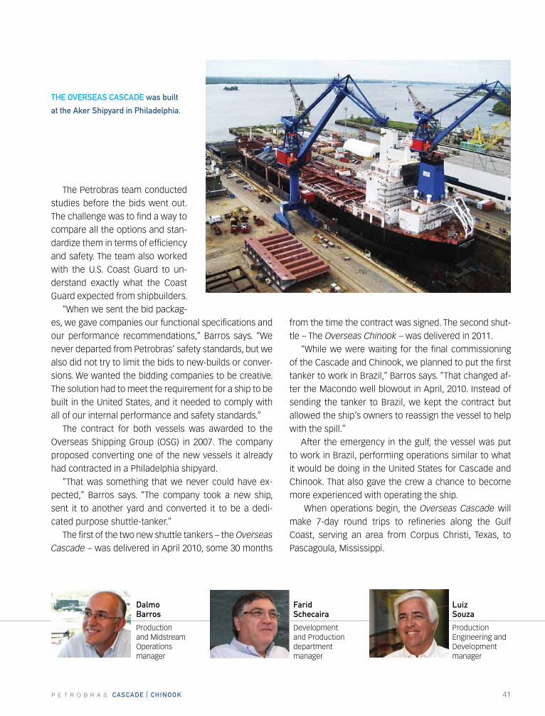
thE OVErsEas cascaDE was built
at the aker shipyard in Philadelphia.
Luiz souza
Production Engineering and Development manager
42 P E T R O B R A S cascaDE | chINOOk
“As we drill more wells, the second tanker will be put into service,” Barros says. “For now, we have enough storage capacity in the early production system to oper-ate with one tanker.”
safE traNsfErsPetrobras has more experience with FPSOs and shuttle tankers than any other operator in the world. In 1980, the industry proposed the first purpose-built shuttle tanker, and it was deployed in the North Sea. The vessel included an innovation known as the North Sea Valve, which has become one of the industry standards for safe ship-to-ship transfers of oil.
There have been many improvements since then. One of the latest is an advanced safety system that links the offloading controls of the FPSO to the loading controls of the shuttle tanker, as Carlos Mastrangelo explains.
“The control systems talk to each other,” he says. “The vessels automatically exchange information, so that both systems act as one.”
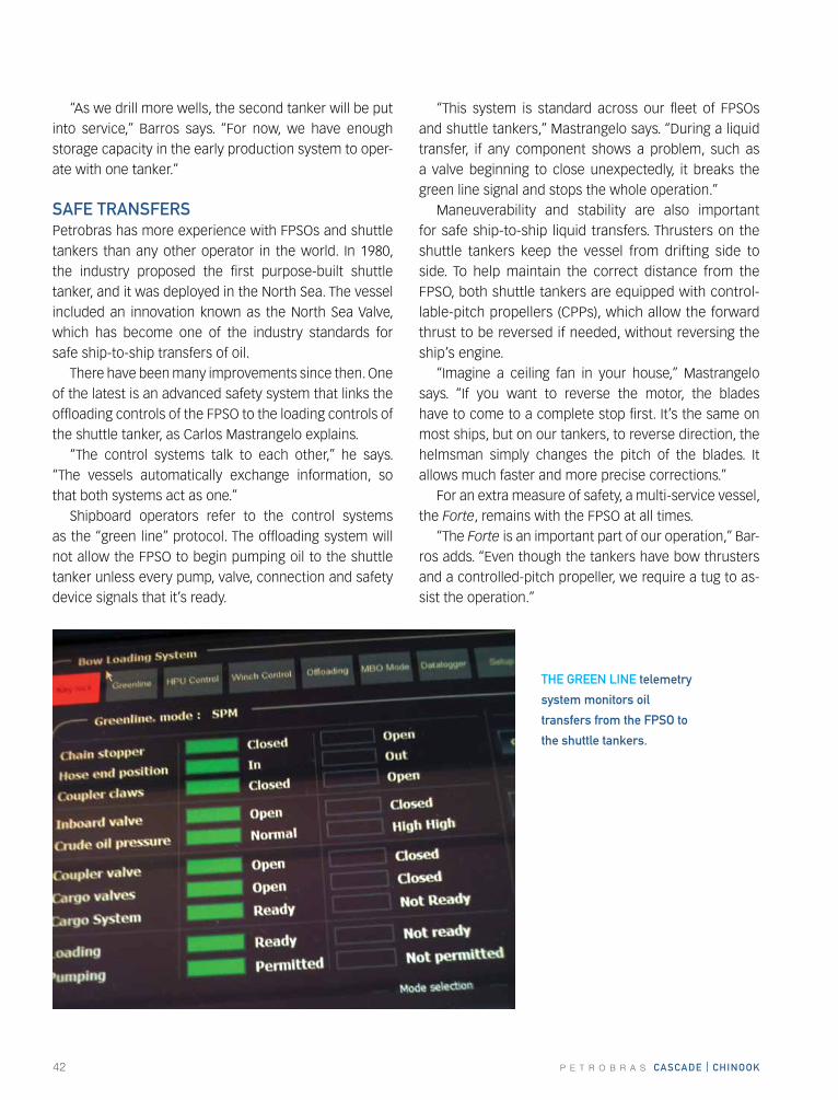
Shipboard operators refer to the control systems as the “green line” protocol. The offloading system will not allow the FPSO to begin pumping oil to the shuttle tanker unless every pump, valve, connection and safety device signals that it’s ready.
“This system is standard across our fleet of FPSOs and shuttle tankers,” Mastrangelo says. “During a liquid transfer, if any component shows a problem, such as a valve beginning to close unexpectedly, it breaks the green line signal and stops the whole operation.”
Maneuverability and stability are also important for safe ship-to-ship liquid transfers. Thrusters on the shuttle tankers keep the vessel from drifting side to side. To help maintain the correct distance from the FPSO, both shuttle tankers are equipped with control-lable-pitch propellers (CPPs), which allow the forward thrust to be reversed if needed, without reversing the ship’s engine.
“Imagine a ceiling fan in your house,” Mastrangelo says. “If you want to reverse the motor, the blades have to come to a complete stop first. It’s the same on most ships, but on our tankers, to reverse direction, the helmsman simply changes the pitch of the blades. It allows much faster and more precise corrections.”
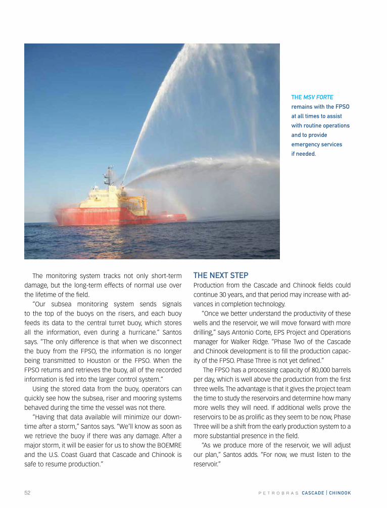
For an extra measure of safety, a multi-service vessel, the Forte, remains with the FPSO at all times.
“The Forte is an important part of our operation,” Bar-ros adds. “Even though the tankers have bow thrusters and a controlled-pitch propeller, we require a tug to as-sist the operation.”
thE GrEEN LINE telemetry
system monitors oil
transfers from the fPsO to
the shuttle tankers.
P E T R O B R A S cascaDE | chINOOk 43
The heavy-duty tug has additional capabilities, including firefighting and spill response. When it’s not pushing tankers around, the tug helps maintain the offloading hose and performs other jobs around the FPSO, such as restrain-ing the rotation of the ship during cer-tain operations.
OIL PIPELINE Vs. shUttLE?In the planning stage of Cascade and Chinook, there was a fair amount of discussion about whether an oil pipeline or a shuttle tanker would be more economical. There were several factors, but the cost of a new oil pipeline, and the fact that it would have to tie into the Gulf of Mexico’s aging pipeline system, were primary considerations.
The question of a gas pipeline was less complicated. It was not so much a commercial decision, however, as it was a way to keep from having to flare some of the gas. A relatively small 6-inch gas pipeline was installed to tie into the Discovery pipeline system, which is 54 miles from the FPSO.
“In the beginning we could use all of the produced gas as fuel for the FPSO,” Barros says. “The ship can burn either diesel or natural gas. But as additional wells come on stream, there will be more gas than we can use offshore, so we need the gas pipeline.”
The decision to build a small pipeline for the gas and tankers to export the oil was more economical in the long run, and having the shuttle tankers added more flexibility to the project. Now other operators in Walker Ridge, including some in partnership with Petrobras, may use shuttle tankers as well.
DELIVErING safEtyA portion of the bid package to build the tankers includ-ed a plan for training the people who would run them. Some of it, such as certification and minimum training on the equipment, is required. In addition, the training for Cascade and Chinook involved a mix of high-tech simulation and hands-on experience for the pilots and key personnel.
“While the shuttles were being built in the united States, we sent their crews to work on some of our tank-ers in the Campos Basin,” Barros says. “Later, when our first u.S. shuttle tanker was released from its duties in the gulf, we sent it to Brazil so the crew could work on their own ship.”
The irony is that when the project began, complying with the Jones Act as it applied to the shuttle tankers was considered to be the major challenge. Not so, ac-cording to Mastrangelo.
“The part of the project that we thought would be the most difficult, the first shuttle tanker, was delivered on the first day of the window, absolutely on time and with no change orders,” he says. “At the end of the day, the Jones Act, in fact, was not a bottleneck for this project.”
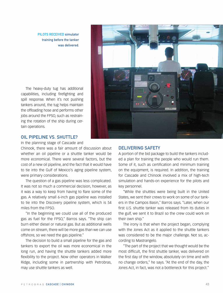
PILOts rEcEIVED simulator
training before the tanker
was delivered.
crEw MEMBEr traINING IN sIMULatOr PhOtO NEEDED
44 P E T R O B R A S cascaDE | chINOOk
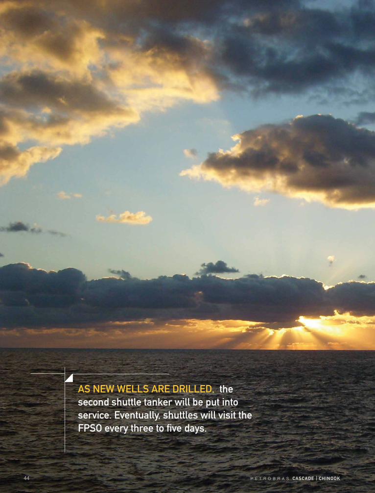
as NEw wELLs arE DrILLED, the second shuttle tanker will be put into service. Eventually, shuttles will visit the fPsO every three to five days.
P E T R O B R A S cascaDE | chINOOk 45

46 P E T R O B R A S cascaDE | chINOOk
P E T R O B R A S cascaDE | chINOOk 47
Petrobras has a long history of successful deepwater operations in Brazil’s Campos Basin, where it produces some 1.7 million barrels of oil and 26.8 million cubic me-ters of natural gas per day from 40 separate fields. That same proven technology and experience is now guiding the operation of Cascade and Chinook.
Operators in the Gulf of Mexico face many challeng-es: potential hurricanes, strong loop currents, and in the case of deepwater developments, a great distance from shore. To help manage these challenges at Cascade and Chinook, Petrobras deployed some of the industry’s most advanced data acquisition and simulation tools.
The technology includes the Production Surveillance Management System and the Digital Oil Fields Tool. There is also a system for monitoring data from the ris-ers and mooring lines, and a dedicated electronic buoy that continuously tracks and records ocean data.
“We monitor all of these systems from both offshore and onshore,” says Luiz Guilherme dos Santos, Opera-tions manager for Cascade and Chinook, and Phase Three project manager.
“To enhance the safety and operational integrity of our fields, we watch every phase of the operation from what we call our ‘Situation Room’ in houston. From there, we not only see what is happening at the mo-ment, we also run ‘what if’ scenarios that predict the effects of any changes in operating conditions. We also made dry-runs of all of the subsea operations before stepping onto the vessel, so we could avoid mistakes and operational problems later on.”
OPEratIONs
sEctION
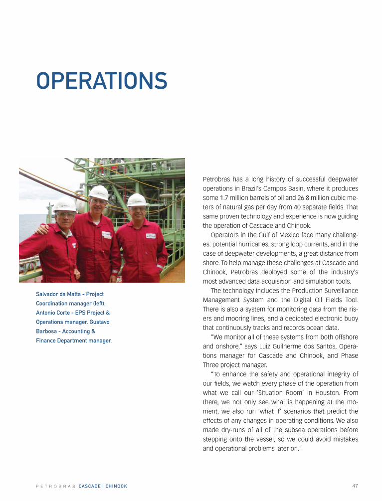
salvador da Matta - Project
coordination manager (left),
antonio corte - EPs Project &
Operations manager, Gustavo
Barbosa - accounting &
finance Department manager.
48 P E T R O B R A S cascaDE | chINOOk
MaNaGING PrODUctIONThe Production Surveillance Management System (PSMS) for Cascade and Chinook contains a set of tools that op-erators need to analyze production in real time. historical data from the PSMS is also available for other applica-tions within Petrobras, and it can be retrieved by autho-rized contractors over the Internet. Although the PSMS for Cascade and Chinook is designed for as many as 16 wells, the early production system required only three.
“The PSMS reports real-time well test information and approved well test results,” Santos says. “The PSMS uses the approved well test volumes and facility rate data to calculate a real-time facility battery factor. Any deviation from within a tolerance range tells the opera-tions and engineering staff that certain wells may need to be re-tested, or that measurement points may need calibration or service.”
The last approved well test data is used in conjunc-tion with the well flow times to calculate the estimated production from each well. Process meters and the gas export meters are also used to calculate the total oil and gas production from the facility. The PSMS provides de-tailed reports that include the latest well test results and test history for each producing well.
thE DIGItaL OIL fIELDs tOOL A key component of the operations management system is the Digital Oil Fields Tool (DOFT), which serves as the pri-mary source of information for safe and reliable production.
“The DOFT uses simulation results to understand the current state of the facility and predict future condi-tions,” Santos says. “The DOFT consists of four separate applications: Real-Time, Look-Ahead, Planning and the Operator Training Simulator.”
For added safety, two identical systems, including all four of these applications, are installed offshore aboard the FPSO, and onshore, in the houston offices of Petrobras.
“The Real-Time (RT) simulator of the Digital Oil Fields Tool serves as a virtual plant of the modeled facility,” Santos says. “It simulates a wide range of information that is not typically measured, such as flow profiles in-side the pipelines.”
The RT simulator indirectly receives its information from the FPSO and the subsea and boosting control sys-tems via a database known as the Petrobras historian. Measurements in the historian continuously update the RT model’s boundary conditions, such as inlet and outlet pressures, and current states such as valve posi-tions and setpoints. The RT simulator also provides the user with a wide range of inferred information, all based on a high-fidelity dynamic process model. The system can automatically tune the model, monitor hydrates and slugs, track pipeline pigs and detect leaks.
The DOFT system includes several distinct real-time, predictive, planning and training modes.
PrEDIctIVE sIMULatOr The predictive or “look-ahead” simulator accepts the ini-tial conditions provided by the real-time simulator and uses them as a starting point for predicting how the sys-tem will react to change. users can ask for the model to operate automatically at user-defined intervals – every hour, for example – or the changes can be input manu-ally. In one hour, the system can predict what will hap-pen as much as 36 hours into the future. At any point, the operator may stop the current look-ahead simula-tion and begin another.
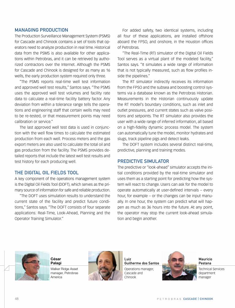
Luiz Guilherme dos santos
Operations manager, Cascade and Chinook
Mauricio Pestana
Technical Services department manager
César Palagi
Walker Ridge Asset manager, Petrobras America
P E T R O B R A S cascaDE | chINOOk 49
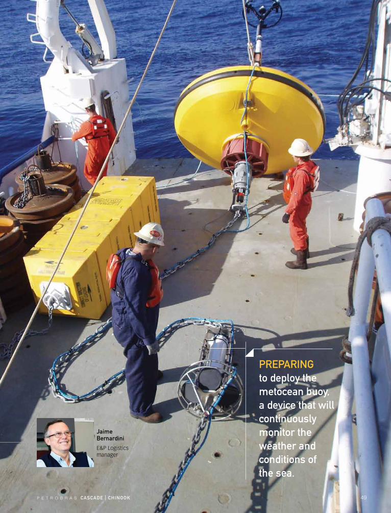
PrEParING to deploy the metocean buoy, a device that will continuously monitor the weather and conditions of the sea.
Jaime Bernardini
E&P Logistics manager
50 P E T R O B R A S cascaDE | chINOOk
thE “what If” sIMULatOrThe planning, or “what if” simulator, allows operators to study the predicted response of the Cascade and Chi-nook system to different operating scenarios.
“This planning mode runs independently from the real-time and look-ahead simulations, and it serves as a comprehensive flow assurance tool,” Santos says. “The planning mode can be run using preconfigured scenar-ios, such as shutting in or restarting a well, or changing the production chokes. We can also run simulations with changes that we introduce ourselves.”
Since the same process model is used for all modes of the Digital Oil Fields Tool, current process conditions from the real-time model can be used as the starting conditions for a planning session.
thE OPEratOr traINING sIMULatOrThe DOFT Operator Training Simulator (OTS) provides “hands on” training for the operators of Cascade and Chi-nook. The OTS operator interface mimics the real control systems. The screens and system responses that the op-erators see during training sessions are identical to what they will see in the field.
wEathEr watchThe Gulf of Mexico is notorious for its hurricanes, which typically form in the Atlantic Ocean between the begin-ning of June and the end of November. All operators in the gulf monitor the weather, and when storms threat-en, they begin shutting in production and evacuating their manned facilities as much as a week ahead of time. The amount of time that a platform remains down depends on the type of facility, the amount of damage from the storm, and the time it takes for the Bureau of Ocean Energy Management, Regulation and Enforce-ment (BOEMRE) and the u.S. Coast Guard to approve a restart. After a major storm, when many facilities are shut down, approvals can take several months even if the facility itself appears undamaged.
“The Cascade and Chinook development is unique,” Santos explains. “In our case, the turret system aboard the FPSO includes a moored buoy that allows us to disconnect the vessel from the wells in case of a hur-ricane. The buoy itself, which is connected to the ris-ers through flexible jumpers, is then submerged safely below the surface until the storm passes. If we have to leave the area, the Digital Oil Fields Tool continues to
monitor the field, so we know immediately after reconnection if we sus-tained any damage to the system.”
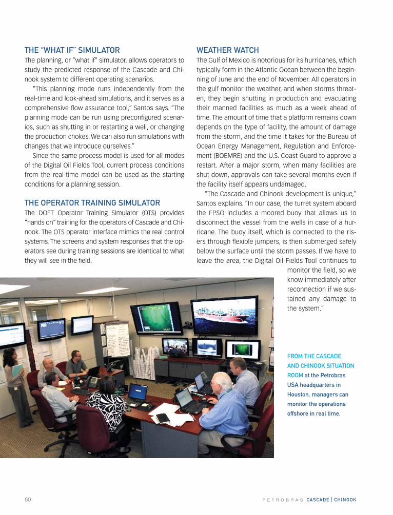
frOM thE cascaDE
aND chINOOk sItUatION
rOOM at the Petrobras
Usa headquarters in
houston, managers can
monitor the operations
offshore in real time.
P E T R O B R A S cascaDE | chINOOk 51
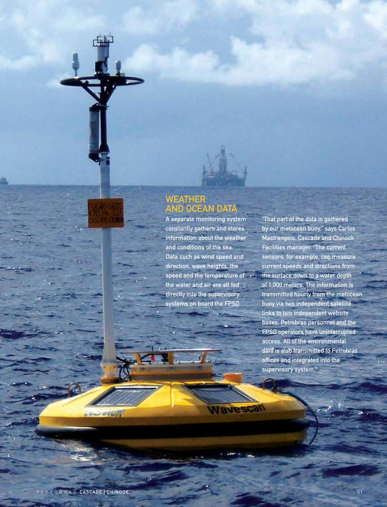
wEathEr aND OcEaN Dataa separate monitoring system constantly gathers and stores information about the weather and conditions of the sea. Data such as wind speed and direction, wave heights, the speed and the temperature of the water and air are all fed directly into the supervisory systems on board the fPsO.
“that part of the data is gathered by our metocean buoy,” says carlos Mastrangelo, cascade and chinook facilities manager. “the current sensors, for example, can measure current speeds and directions from the surface down to a water depth of 1,000 meters. the information is transmitted hourly from the metocean buoy via two independent satellite links to two independent website bases. Petrobras personnel and the fPsO operators have uninterrupted access. all of the environmental data is also transmitted to Petrobras offices and integrated into the supervisory system.”
52 P E T R O B R A S cascaDE | chINOOk
The monitoring system tracks not only short-term damage, but the long-term effects of normal use over the lifetime of the field.
“Our subsea monitoring system sends signals to the top of the buoys on the risers, and each buoy feeds its data to the central turret buoy, which stores all the information, even during a hurricane.” Santos says. “The only difference is that when we disconnect the buoy from the FPSO, the information is no longer being transmitted to houston or the FPSO. When the FPSO returns and retrieves the buoy, all of the recorded information is fed into the larger control system.”
using the stored data from the buoy, operators can quickly see how the subsea, riser and mooring systems behaved during the time the vessel was not there.
“having that data available will minimize our down-time after a storm,” Santos says. “We’ll know as soon as we retrieve the buoy if there was any damage. After a major storm, it will be easier for us to show the BOEMRE and the u.S. Coast Guard that Cascade and Chinook is safe to resume production.”
thE MsV fOrtE
remains with the fPsO
at all times to assist
with routine operations
and to provide
emergency services
if needed.
thE NExt stEPProduction from the Cascade and Chinook fields could continue 30 years, and that period may increase with ad-vances in completion technology.
“Once we better understand the productivity of these wells and the reservoir, we will move forward with more drilling,” says Antonio Corte, EPS Project and Operations manager for Walker Ridge. “Phase Two of the Cascade and Chinook development is to fill the production capac-ity of the FPSO. Phase Three is not yet defined.”
The FPSO has a processing capacity of 80,000 barrels per day, which is well above the production from the first three wells. The advantage is that it gives the project team the time to study the reservoirs and determine how many more wells they will need. If additional wells prove the reservoirs to be as prolific as they seem to be now, Phase Three will be a shift from the early production system to a more substantial presence in the field.
“As we produce more of the reservoir, we will adjust our plan,” Santos adds. “For now, we must listen to the reservoir.”
P E T R O B R A S cascaDE | chINOOk 53
54 P E T R O B R A S CASCADE | CHINOOK
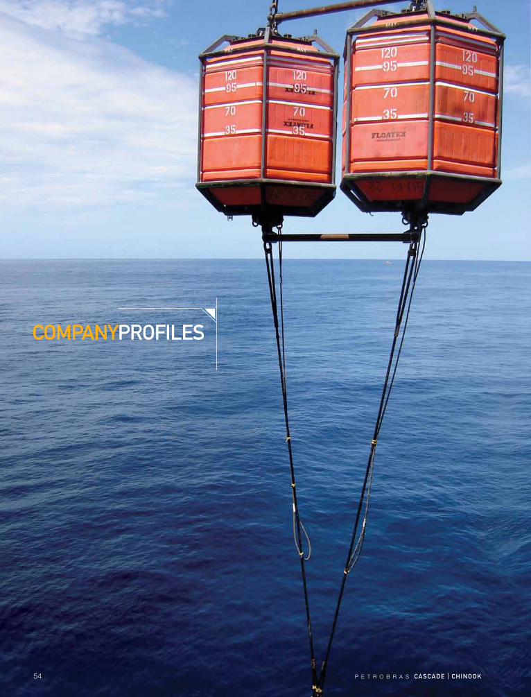
COmpANyprOfIlES
P E T R O B R A S CASCADE | CHINOOK 55
C o m p a n y p r o f i l e C o m p l i a n C e T e C h n o l o g y g r o u p
WEB-BASED SySTEm mANAGES SAfETy, ENVIrONmENTAl COmplIANCE AT DEEpWATEr CASCADE AND CHINOOK
COmplIANCE TECHNOlOGy GrOup3233 Florida Ave., Suite 200Kenner, LA 70065Tel: 866-494-2861 (toll-free)www.compliancetechnologygroup.com
Fully aware that meeting and validating all
federal and state government regulations
for drilling and production operations in
U.S. waters was a daunting task, Petrobras
made sure to acquire for its Cascade and
Chinook deepwater development what it
deemed to be the most complete compli-
ance management system available.
Petrobras’ choice was the SMART sys-
tem developed by Compliance Technology
Group of New Orleans. This two-pronged,
web based compliance software solution
gives offshore operators the ability to:
• ApplytheSMART14C module to sched-
ule and record all safety device testing
as set out by the intense requirements
of API RP 14C.
• EmploytheSMARTPlus module to man-
age all other compliance record-keeping
and reporting items, including those
contained in U.S. Coast Guard rules for
Fixed or Floating facilities, as well as
thoserequiredunderEPA,DOT,DOI,ISO
14001 and other federal, state or corpo-
rate policies.
• Utilize SMART Files to store electronic
copies of all other compliance docu-
ments, including vessel certifications,
safety management certificates, and
ship’s personnel certifications.
With SMART, operators do not miss tests,
inspections or other compliance activities.
Because it is web-based, the SMART system
makes reports and other data available to all
concerned parties, which assures corporate
governance and accountability.
Significant changes in federal regu-
lations resulting from the deepwater
Macondo blowout and oil spill made it even
more critical for Petrobras to have a leading-
edge compliance system in place that can
be updated immediately upon the hand-
ing down of any such new rules and poli-
cies. According to Compliance Technology
Group, these current and future changes are
being met as they are instituted by prompt
updates to the SMART system’s software.
Founded in 2001, Compliance Technology
Group provides the technical expertise nec-
essary to design and build solutions to chal-
lenges in the oilfield environment.
C o m p a n y p r o f i l e i n D e X
AKEr SOluTIONS 56
BAKEr HuGHES 58
BW OffSHOrE 60
COmplIANCE TECHNOlOGy GrOup 55
DEuTSCH 61
DEVIN INTErNATIONAl 62
EmErSON 64
fmC TECHNOlOGIES 66
GrANHErNE 68
HAllIBurTON 69
HEErEmA mArINE CONTrACTOrS uS INC. 74
JumBO OffSHOrE 70
NAlCO ENErGy SErVICES 72
OSG SHIp mANAGEmENT, INC. 75
pETrOQuIp ENErGy SErVICES 76
prOTECHNICS, DIV Of COrE lABOrATOrIES 78
SCHlumBErGEr 80
SEADrIll 82
SuBSEA 7 86
TECHNIp 84
TENArIS 87
VAllOurEC & mANNESmANN uSA COrpOrATION 88
VEOlIA ES SpECIAl SErVICES, INC. 89
56 P E T R O B R A S CASCADE | CHINOOK
C o m p a n y p r o f i l e a k e r S o l u T i o n S
AKEr SOluTIONS prOVIDED pOWEr, CONTrOl umBIlICAlS TO CASCADE AND CHINOOK DEVElOpmENT
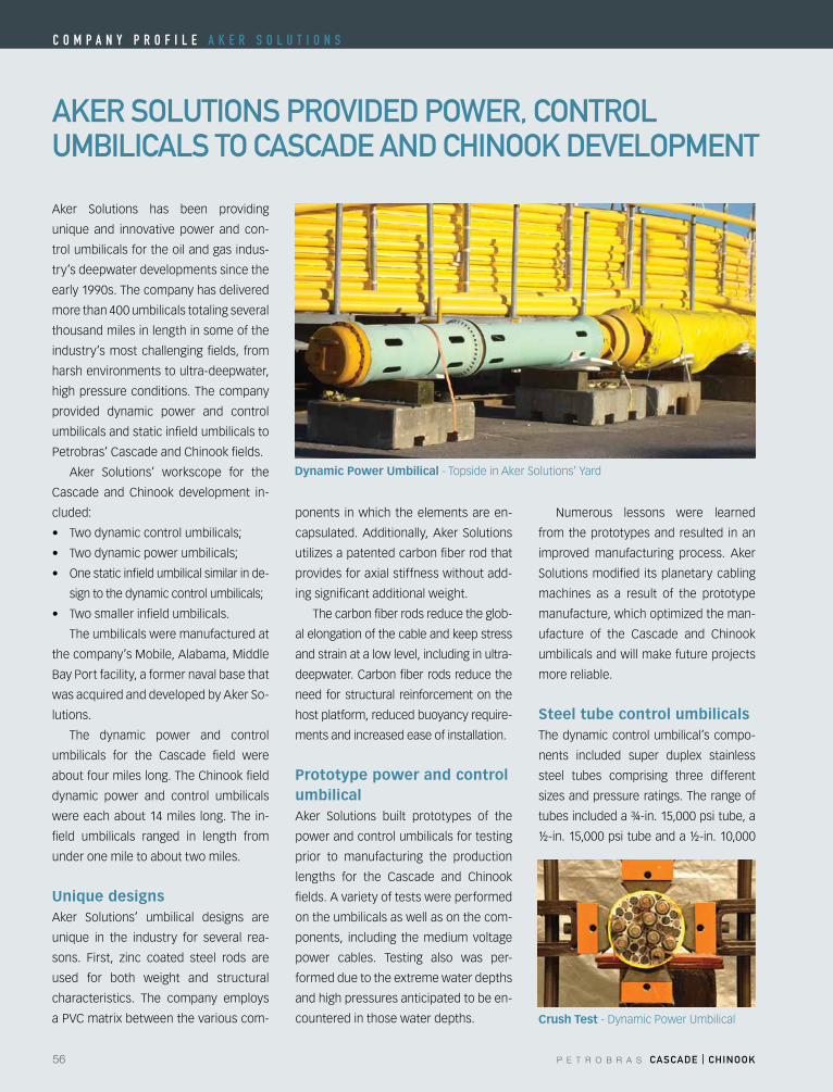
Aker Solutions has been providing
unique and innovative power and con-
trol umbilicals for the oil and gas indus-
try’s deepwater developments since the
early 1990s. The company has delivered
more than 400 umbilicals totaling several
thousand miles in length in some of the
industry’s most challenging fields, from
harsh environments to ultra-deepwater,
high pressure conditions. The company
provided dynamic power and control
umbilicals and static infield umbilicals to
Petrobras’ Cascade and Chinook fields.
Aker Solutions’ workscope for the
Cascade and Chinook development in-
cluded:
• Twodynamiccontrolumbilicals;
• Twodynamicpowerumbilicals;
• Onestaticinfieldumbilicalsimilarinde-
signtothedynamiccontrolumbilicals;
• Twosmallerinfieldumbilicals.
The umbilicals were manufactured at
the company’s Mobile, Alabama, Middle
Bay Port facility, a former naval base that
was acquired and developed by Aker So-
lutions.
The dynamic power and control
umbilicals for the Cascade field were
about four miles long. The Chinook field
dynamic power and control umbilicals
were each about 14 miles long. The in-
field umbilicals ranged in length from
under one mile to about two miles.
Unique designsAker Solutions’ umbilical designs are
unique in the industry for several rea-
sons. First, zinc coated steel rods are
used for both weight and structural
characteristics. The company employs
a PVC matrix between the various com-
ponents in which the elements are en-
capsulated. Additionally, Aker Solutions
utilizesapatentedcarbonfiberrodthat
provides for axial stiffness without add-
ing significant additional weight.
The carbon fiber rods reduce the glob-
al elongation of the cable and keep stress
and strain at a low level, including in ultra-
deepwater. Carbon fiber rods reduce the
need for structural reinforcement on the
host platform, reduced buoyancy require-
ments and increased ease of installation.
Prototype power and control umbilicalAker Solutions built prototypes of the
power and control umbilicals for testing
prior to manufacturing the production
lengths for the Cascade and Chinook
fields. A variety of tests were performed
on the umbilicals as well as on the com-
ponents, including the medium voltage
power cables. Testing also was per-
formed due to the extreme water depths
and high pressures anticipated to be en-
countered in those water depths.
Numerous lessons were learned
from the prototypes and resulted in an
improved manufacturing process. Aker
Solutions modified its planetary cabling
machines as a result of the prototype
manufacture,whichoptimizedtheman-
ufacture of the Cascade and Chinook
umbilicals and will make future projects
more reliable.
Steel tube control umbilicalsThe dynamic control umbilical’s compo-
nents included super duplex stainless
steel tubes comprising three different
sizesandpressureratings.Therangeof
tubes included a ¾-in. 15,000 psi tube, a
½-in. 15,000 psi tube and a ½-in. 10,000
Crush Test-DynamicPowerUmbilical
Dynamic Power Umbilical - Topside in Aker Solutions’ Yard
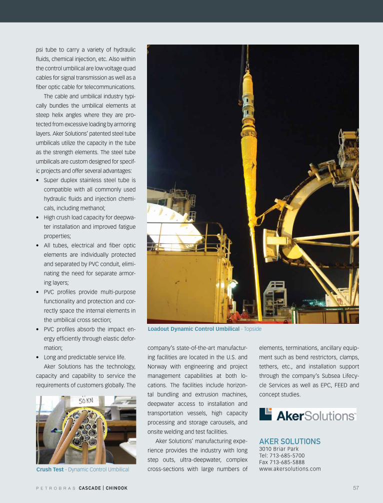
P E T R O B R A S CASCADE | CHINOOK 57
AKEr SOluTIONS3010 Briar ParkTel: 713-685-5700Fax 713-685-5888 www.akersolutions.com
psi tube to carry a variety of hydraulic
fluids, chemical injection, etc. Also within
the control umbilical are low voltage quad
cables for signal transmission as well as a
fiber optic cable for telecommunications.
The cable and umbilical industry typi-
cally bundles the umbilical elements at
steep helix angles where they are pro-
tected from excessive loading by armoring
layers. Aker Solutions’ patented steel tube
umbilicalsutilizethecapacity inthetube
as the strength elements. The steel tube
umbilicals are custom designed for specif-
ic projects and offer several advantages:
• Super duplex stainless steel tube is
compatible with all commonly used
hydraulic fluids and injection chemi-
cals,includingmethanol;
• Highcrushloadcapacityfordeepwa-
ter installation and improved fatigue
properties;
• All tubes, electrical and fiber optic
elements are individually protected
and separated by PVC conduit, elimi-
nating the need for separate armor-
inglayers;
• PVC profiles provide multi-purpose
functionality and protection and cor-
rectly space the internal elements in
theumbilicalcrosssection;
• PVC profiles absorb the impact en-
ergy efficiently through elastic defor-
mation;
• Longandpredictableservicelife.
Aker Solutions has the technology,
capacity and capability to service the
requirements of customers globally. The
company’s state-of-the-art manufactur-
ing facilities are located in the U.S. and
Norway with engineering and project
management capabilities at both lo-
cations. The facilities include horizon-
tal bundling and extrusion machines,
deepwater access to installation and
transportation vessels, high capacity
processing and storage carousels, and
onsite welding and test facilities.
Aker Solutions’ manufacturing expe-
rience provides the industry with long
step outs, ultra-deepwater, complex
cross-sections with large numbers of
elements, terminations, ancillary equip-
ment such as bend restrictors, clamps,
tethers, etc., and installation support
through the company’s Subsea Lifecy-
cle Services aswell as EPC, FEED and
concept studies.
Loadout Dynamic Control Umbilical - Topside
Crush Test-DynamicControlUmbilical
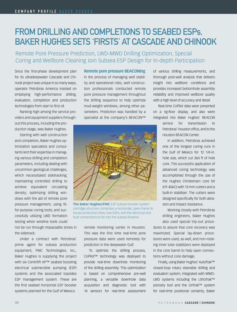
58 P E T R O B R A S CASCADE | CHINOOK
C o m p a n y p r o f i l e B a k e r h u g h e S
frOm DrIllING AND COmplETIONS TO SEABED ESps, BAKEr HuGHES SETS ‘fIrSTS’ AT CASCADE AND CHINOOK
Since the first-phase development plan
for its ultradeepwater Cascade and Chi-
nook project was unique in so many ways,
operator Petrobras America insisted on
employing high-performance drilling,
evaluation, completion and production
technologies from start to first oil.
Ranking high among the service pro-
viders and equipment suppliers through-
out this process, including the pro-
ductionstage,wasBakerHughes.
Starting with well construction
andcompletion,BakerHughesop-
timization specialists and consul-
tants lent their expertise in manag-
ing various drilling and completion
parameters, including dealing with
uncommon geological challenges,
which necessitated sidetracking;
maintaining controlled drilling to
achieve equivalent circulating
density; optimizing drilling win-
dows with the aid of remote pore
pressure management; using fit-
for-purposecoringtools;andsuc-
cessfully utilizing LWD formation
testing when wireline tools could
notberunthroughimpassablezonesin
the sidetrack.
Under a contract with Petrobras’
prime agent for subsea production
equipment, FMC Technologies, Inc.,
Baker Hughes is supplying the project
with six Centrilift XP™ seabed boosting
electrical submersible pumping (ESP)
systems and the associated topsides
ESP management system. These are
thefirst seabedhorizontalESPbooster
systems planned for the Gulf of Mexico.
Remote pore pressure BEACONing In the process of managing well stabil-
ity and operational risks, well construc-
tion professionals conducted remote
pore pressure management throughout
the drilling sequence to help optimize
mud-weight windows, among other pa-
rameters. Prediction was handled by a
specialist at the company’s BEACON™
remote monitoring center in Houston.
This was the first time real-time pore
pressure data were used remotely for
prediction in the deepwater Gulf.
To optimize the drilling process,
CoPilot™ technology was deployed to
provide real-time downhole monitoring
ofthedrillingassembly.Thisoptimization
is based on comprehensive pre-well
planning, a versatile downhole data
acquisition and diagnostic tool with
14 sensors for real-time assessment
of various drilling measurements, and
thorough post-well analysis that delivers
insight into wellbore conditions and
provides increased bottomhole assembly
reliability and improved wellbore quality
with a high level of accuracy and detail.
Real-time CoPilot data were presented
on a rig-floor display, and also were
integrated into Baker Hughes’ BEACON
service for transmission to
Petrobras’Houstonoffice,andtothe
HoustonBEACONCenter.
In addition, Petrobras achieved
one of the longest coring runs in
the Gulf of Mexico for 12 1/4-in.
holesize,whichcut360 ftofhole
core. This successful application of
advanced coring technology was
accomplished through the use of
the Hughes Christensen core bit
(HT-406C)with13mmcuttersanda
built-instabilizer.Thecutterswere
designed specifically for both abra-
sion and impact resistance.
Working closely with Petrobras
drilling engineers, Baker Hughes
also used special trip-out proce-
dures to assure that core recovery was
maximized. Special lay-down proce-
dures were used, as well, and non-rotat-
inginnertubestabilizersweredeployed
in the core barrel to help open connec-
tions without core damage.
Finally,usingBakerHughes’AutoTrak™
closed-loop rotary steerable drilling and
evaluationsystem,integratedwithMWD-
LWD systems including the LithoTrak™
porosity tool and the OnTrak™ system
for real-time positional certainty, Baker
RemotePorePressurePrediction,LWD-MWDDrillingOptimization,SpecialCoringandWellboreCleaningJoinSubseaESPDesignforIn-depthParticipation
The Baker Hughes/FMCESPsubseaboostersystemcartridgestructurecomprisesahorizontal,open-frametohouseproductionlines,twoESPs,andtheelectricalandfluid connections to tie into the subsea flowline.
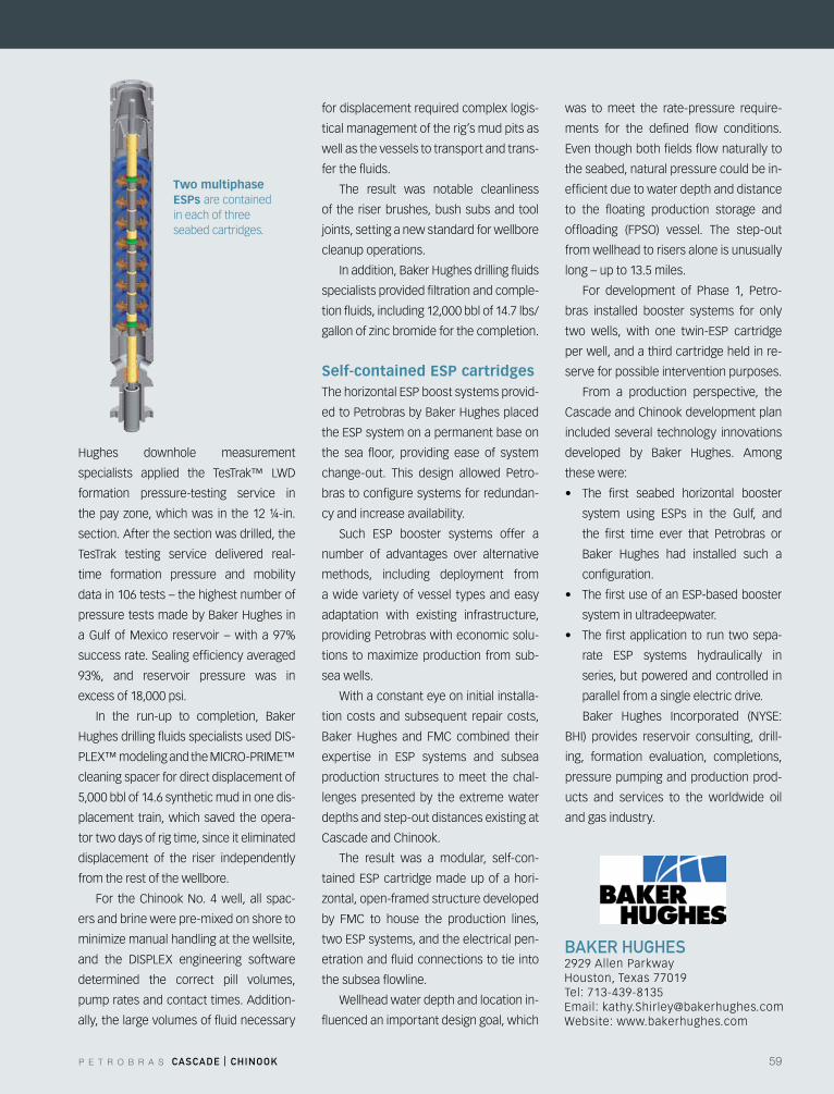
P E T R O B R A S CASCADE | CHINOOK 59
frOm DrIllING AND COmplETIONS TO SEABED ESps, BAKEr HuGHES SETS ‘fIrSTS’ AT CASCADE AND CHINOOK
BAKEr HuGHES2929 Allen ParkwayHouston,Texas77019Tel: 713-439-8135Email:[email protected]: www.bakerhughes.com
Hughes downhole measurement
specialists applied the TesTrak™ LWD
formation pressure-testing service in
thepayzone,whichwas in the12¼-in.
section. After the section was drilled, the
TesTrak testing service delivered real-
time formation pressure and mobility
data in 106 tests – the highest number of
pressuretestsmadebyBakerHughesin
a Gulf of Mexico reservoir – with a 97%
success rate. Sealing efficiency averaged
93%, and reservoir pressure was in
excess of 18,000 psi.
In the run-up to completion, Baker
HughesdrillingfluidsspecialistsusedDIS-
PLEX™modelingandtheMICRO-PRIME™
cleaning spacer for direct displacement of
5,000 bbl of 14.6 synthetic mud in one dis-
placement train, which saved the opera-
tor two days of rig time, since it eliminated
displacement of the riser independently
from the rest of the wellbore.
For the Chinook No. 4 well, all spac-
ers and brine were pre-mixed on shore to
minimizemanualhandlingatthewellsite,
and the DISPLEX engineering software
determined the correct pill volumes,
pump rates and contact times. Addition-
ally, the large volumes of fluid necessary
for displacement required complex logis-
tical management of the rig’s mud pits as
well as the vessels to transport and trans-
fer the fluids.
The result was notable cleanliness
of the riser brushes, bush subs and tool
joints, setting a new standard for wellbore
cleanup operations.
Inaddition,BakerHughesdrillingfluids
specialists provided filtration and comple-
tion fluids, including 12,000 bbl of 14.7 lbs/
gallonofzincbromideforthecompletion.
Self-contained ESP cartridgesThehorizontalESPboostsystemsprovid-
edtoPetrobrasbyBakerHughesplaced
theESPsystemonapermanentbaseon
the sea floor, providing ease of system
change-out. This design allowed Petro-
bras to configure systems for redundan-
cy and increase availability.
Such ESP booster systems offer a
number of advantages over alternative
methods, including deployment from
a wide variety of vessel types and easy
adaptation with existing infrastructure,
providing Petrobras with economic solu-
tions tomaximizeproduction fromsub-
sea wells.
With a constant eye on initial installa-
tion costs and subsequent repair costs,
Baker Hughes and FMC combined their
expertise in ESP systems and subsea
production structures to meet the chal-
lenges presented by the extreme water
depths and step-out distances existing at
Cascade and Chinook.
The result was a modular, self-con-
tainedESPcartridgemadeupofahori-
zontal,open-framedstructuredeveloped
by FMC to house the production lines,
twoESPsystems,andtheelectricalpen-
etration and fluid connections to tie into
the subsea flowline.
Wellhead water depth and location in-
fluenced an important design goal, which
was to meet the rate-pressure require-
ments for the defined flow conditions.
Eventhoughbothfieldsflownaturallyto
the seabed, natural pressure could be in-
efficient due to water depth and distance
to the floating production storage and
offloading (FPSO) vessel. The step-out
from wellhead to risers alone is unusually
long – up to 13.5 miles.
For development of Phase 1, Petro-
bras installed booster systems for only
two wells, with one twin-ESP cartridge
per well, and a third cartridge held in re-
serve for possible intervention purposes.
From a production perspective, the
Cascade and Chinook development plan
included several technology innovations
developed by Baker Hughes. Among
these were:
• The first seabed horizontal booster
system using ESPs in the Gulf, and
the first time ever that Petrobras or
Baker Hughes had installed such a
configuration.
• ThefirstuseofanESP-basedbooster
system in ultradeepwater.
• Thefirstapplication to run twosepa-
rate ESP systems hydraulically in
series, but powered and controlled in
parallel from a single electric drive.
Baker Hughes Incorporated (NYSE:
BHI) provides reservoir consulting, drill-
ing, formation evaluation, completions,
pressure pumping and production prod-
ucts and services to the worldwide oil
and gas industry.
Two multiphase ESPs are contained in each of three seabed cartridges.
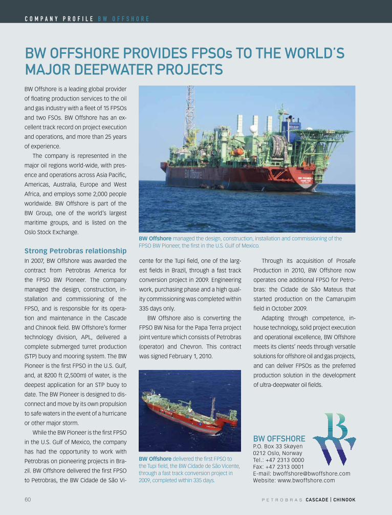
60 P E T R O B R A S CASCADE | CHINOOK
C o m p a n y p r o f i l e B W o f f S h o r e
BW Offshore managed the design, construction, installation and commissioning of the FPSOBWPioneer,thefirstintheU.S.GulfofMexico.
BW OffSHOrE prOVIDES fpSOs TO THE WOrlD’S mAJOr DEEpWATEr prOJECTSBWOffshoreisaleadingglobalprovider
of floating production services to the oil
andgasindustrywithafleetof15FPSOs
and twoFSOs.BWOffshorehasanex-
cellent track record on project execution
and operations, and more than 25 years
of experience.
The company is represented in the
major oil regions world-wide, with pres-
ence and operations across Asia Pacific,
Americas, Australia, Europe and West
Africa, and employs some 2,000 people
worldwide. BW Offshore is part of the
BW Group, one of the world’s largest
maritime groups, and is listed on the
OsloStockExchange.
Strong Petrobras relationshipIn2007,BWOffshorewasawarded the
contract from Petrobras America for
the FPSO BW Pioneer. The company
managed the design, construction, in-
stallation and commissioning of the
FPSO, and is responsible for its opera-
tion and maintenance in the Cascade
andChinookfield.BWOffshore’sformer
technology division, APL, delivered a
complete submerged turret production
(STP) buoy and mooring system. The BW
PioneeristhefirstFPSOintheU.S.Gulf,
and, at 8200 ft (2,500m) of water, is the
deepest application for an STP buoy to
date. The BW Pioneer is designed to dis-
connect and move by its own propulsion
to safe waters in the event of a hurricane
or other major storm.
WhiletheBWPioneeristhefirstFPSO
in the U.S. Gulf of Mexico, the company
has had the opportunity to work with
Petrobras on pioneering projects in Bra-
zil.BWOffshoredeliveredthefirstFPSO
to Petrobras, the BW Cidade de São Vi-
cente for the Tupi field, one of the larg-
est fields in Brazil, through a fast track
conversionproject in2009.Engineering
work, purchasing phase and a high qual-
ity commissioning was completed within
335 days only.
BW Offshore also is converting the
FPSOBWNisaforthePapaTerraproject
joint venture which consists of Petrobras
(operator) and Chevron. This contract
was signed February 1, 2010.
Through its acquisition of Prosafe
Production in 2010, BW Offshore now
operatesoneadditionalFPSOforPetro-
bras: the Cidade de São Mateus that
started production on the Camarupim
fieldinOctober2009.
Adapting through competence, in-
house technology, solid project execution
andoperationalexcellence,BWOffshore
meets its clients’ needs through versatile
solutions for offshore oil and gas projects,
and can deliver FPSOs as the preferred
production solution in the development
of ultra-deepwater oil fields.
BW OffSHOrE P.O.Box33Skøyen0212Oslo,NorwayTel.: +47 2313 0000Fax: +47 2313 0001E-mail:[email protected]: www.bwoffshore.com
BW OffshoredeliveredthefirstFPSOtothe Tupi field, the BW Cidade de São Vicente, through a fast track conversion project in 2009, completed within 335 days.

P E T R O B R A S CASCADE | CHINOOK 61
DEuTSCH DEVElOpED INTErCONNECTION SySTEm fOr CASCADE AND CHINOOK prOJECT
DEuTSCH27628CommerceOaksDriveConroe, Texas 77385Tel: +1 713 623 1925Fax: +1 713 344 1418Email:[email protected]: www.deutsch.net
Deutsch has a long illustrious history go-
ing back to 1938 when the company was
created. It designs, manufactures and sells
connection systems in three main seg-
ments – industrial volumes connectors for
the transportation sector, high tech con-
nectors for aerospace, transportation and
heavyindustries;andtoptechnologiesfor
extremeconnectionsinoffshore.Deutsch
develops a variety of interconnection so-
lutions for harsh environments and it has
an extensive research and development
laboratory for fiber optic, signal and power
connection systems.
The company, with around 3,000
employees globally and $561 million in
turnover in 2010, was bought by French
company, Wendel Investment, in 2006.
DeutschisheadquarteredinNewYork
and has manufacturing and sales centers
inadozencountriesincludingChina,India
and Israel. Its offshore operation, which
forms a major link with subsea system
providers and oil and gas operators, is con-
centrated in Le Mans, France to address
topside, subsea and downhole areas. The
company recently opened a facility in
Houston,dedicated tooffshoreactivities,
to develop a competence center for signal
connectors and to offer a stronger local
technical support to its customers.
Deutsch experience and capabilitiesDeutschwasakeypartnertooilcompa-
nies since the beginning of the subsea
processing and boosting industry. Starting
in 1984, the company developed a subsea
mateable connector installed on a subsea
multiphase pump, which was tested in the
Fusa fjord, in Norway. This testing led to
the patent of the helico-axial multiphase
pump principal, now used by key major
players in the subsea pumping and boost-
ing market.
Following its first power project in a
subseaenvironment,Deutschworkedon
several subsea projects offshore Norway,
and around the world during the 90’s and
early 2000’s.
Deutsch is addressing three connec-
tors markets, power, signal and optical,
on a system level view, and is covering all
applications, from downhole to subsea,
to provide its clients a full solution for all
connection systems in the harsh subsea
environment.
Cascade and Chinook project Taking advantage of the different tech-
nologies available within all of the com-
pany’s divisions, FMC Technologies
awarded Deutsch a feasibility study for
ahighvoltage(HV),highdifferentialpres-
sure(HdP)penetratortobeusedonthe
Cascade and Chinook fields. This HV
HdP penetrator is one of the key com-
ponents of the overall subsea boosting
system, as it allows use of the seabed
ESPbasedpumpingsystem.Thepenetra-
tor is required to handle the deepwater
requirement, and the extreme pressures
and temperatures from the well stream.
Followingthisfeasibility,theoverallHV
wet mateable connection system, devel-
oped and qualified to the latest industry
standards, were awarded to Deutsch by
FMC Technologies.
The scope of work consisted of three
different tasks:
• Design, manufacture and qualify an
HV HdP Penetrator system, including
interfaces towards the pump internals
interfaces, and interfaces towards the
overallpumpcartridgedesignandHV
harnesses;
• Design, manufacture and qualify a
splitter box, which allows the supply
of power from one power triad in the
umbilical to two subsea pump units.
• An EPC contract for the overall HV
connection system, including power
distributionunitconnectors,HVflying
leads and pump harnesses subassem-
blies, and all necessary accessories,
such as test connectors, spares, etc.
The Cascade and Chinook project
was a unique opportunity to demonstrate
again Deutsch’s capability on the HV
power connectors market, as well as for
high pressure, high temperature applica-
tions. It also demonstrates the company’s
capability of handling large scale projects,
including engineering, manufacturing,
testing and on-site services.
Deutsch Penetrator system installed on FMC’s pump flange, after termination ofMLE(MotorLeadExtension)
C o m p a n y p r o f i l e D e u T S C h
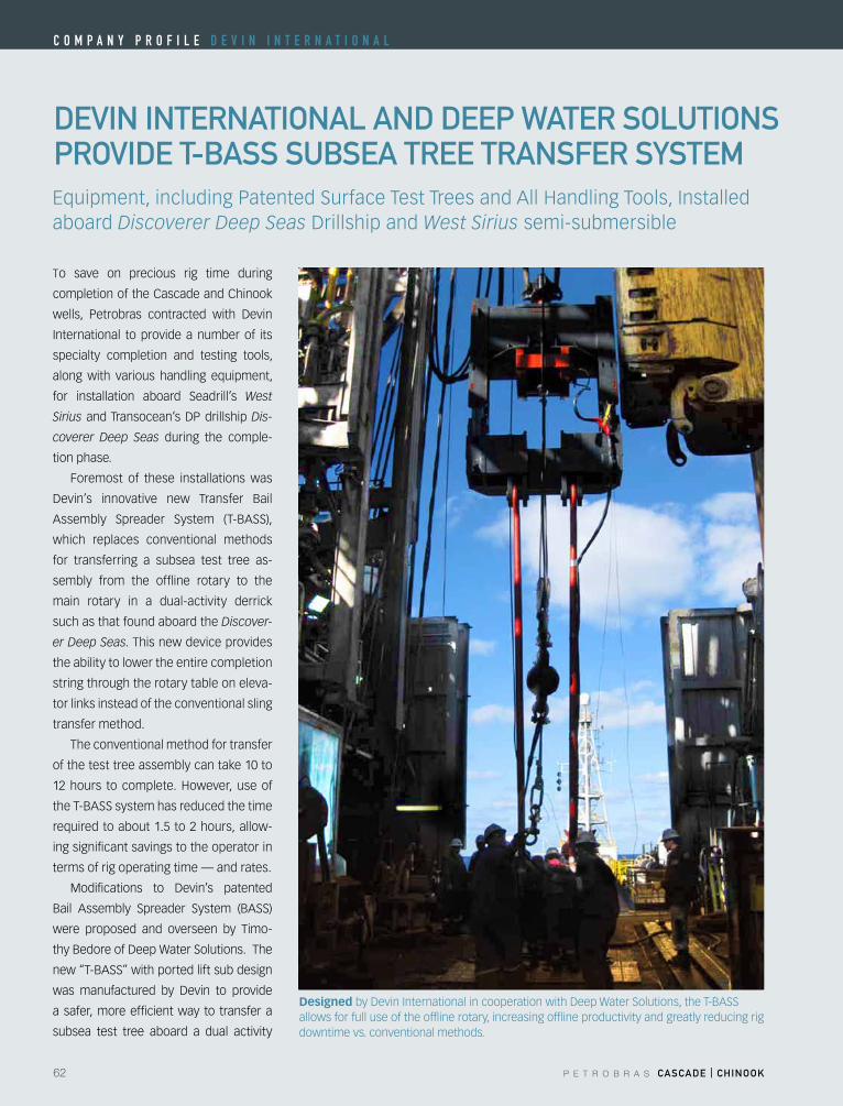
62 P E T R O B R A S CASCADE | CHINOOK
C o m p a n y p r o f i l e D e V i n i n T e r n a T i o n a l
DEVIN INTErNATIONAl AND DEEp WATEr SOluTIONS prOVIDE T-BASS SuBSEA TrEE TrANSfEr SySTEm
To save on precious rig time during
completion of the Cascade and Chinook
wells, Petrobras contracted with Devin
International to provide a number of its
specialty completion and testing tools,
along with various handling equipment,
for installation aboard Seadrill’s West
SiriusandTransocean’sDPdrillshipDis-
coverer Deep Seas during the comple-
tion phase.
Foremost of these installations was
Devin’s innovative new Transfer Bail
Assembly Spreader System (T-BASS),
which replaces conventional methods
for transferring a subsea test tree as-
sembly from the offline rotary to the
main rotary in a dual-activity derrick
such as that found aboard the Discover-
er Deep Seas. This new device provides
the ability to lower the entire completion
string through the rotary table on eleva-
tor links instead of the conventional sling
transfer method.
The conventional method for transfer
of the test tree assembly can take 10 to
12hours to complete.However, useof
the T-BASS system has reduced the time
required to about 1.5 to 2 hours, allow-
ing significant savings to the operator in
terms of rig operating time — and rates.
Modifications to Devin’s patented
Bail Assembly Spreader System (BASS)
were proposed and overseen by Timo-
thyBedoreofDeepWaterSolutions.The
new “T-BASS” with ported lift sub design
was manufactured by Devin to provide
a safer, more efficient way to transfer a
subsea test tree aboard a dual activity
Equipment,includingPatentedSurfaceTestTreesandAllHandlingTools,Installedaboard Discoverer Deep SeasDrillshipandWest Sirius semi-submersible
DesignedbyDevinInternationalincooperationwithDeepWaterSolutions,theT-BASSallows for full use of the offline rotary, increasing offline productivity and greatly reducing rig downtime vs. conventional methods.
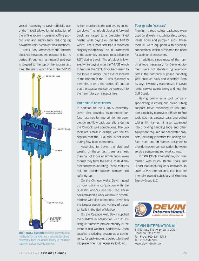
P E T R O B R A S CASCADE | CHINOOK 63
DEVIN INTErNATIONAl11757 Katy Freeway Suite 300Houston,TX77079Toll Free: 800-324-1213Tel: 281-598-6830www.devindevin.com
vessel. According toDevin officials, use
oftheT-BASSallowsforfullutilizationof
the offline rotary, increasing offline pro-
ductivity and significantly reducing rig
downtime versus conventional methods.
The T BASS attaches to the forward
block via elevators and elevator links. A
ported lift sub with an integral pad-eye
is torqued to the top of the subsea test
tree. The main winch line of the T-BASS
is then attached to the pad-eye by an 85-
ton clevis. The rig’s aft block and forward
block are raised to a pre-determined
height, while paying out on the T-BASS
winch. The subsea test tree is raised on
slings by the aft block. The PRS is attached
totheassemblyandusedtostabilizethe
SSTT during travel. The aft block is low-
ered while paying in on the T-BASS winch
totransfertheSSTT.Oncetransferredto
the forward rotary, the elevator located
at the bottom of the T Bass assembly is
then closed onto the ported lift sub so
that the subsea tree can be lowered into
the main rotary on elevator links.
Patented test trees In addition to the T BASS assembly,
Devin also provided its patented Sur-
face Test Tree for intervention for com-
pletion and flow back operations during
the Chinook well completions. The two
tools are similar in design, with the ex-
ception that the DualMini is not used
during flow back operations.
According to Devin, the size and
weight of these test trees are less
than half of those of similar tools, even
though they have the same inside diam-
eter and pressure rating. These features
help to provide quicker, simpler and
safer rig-up.
On the Chinookwells, Devin rigged
up long bails in conjunction with the
DualMiniandSurfaceTestTree.These
bails provided a work window to accom-
modatewirelineoperations.Devinhas
the largest supply and variety of eleva-
tor bails in the Gulf of Mexico.
On the Cascade well, Devin supplied
the stabilizer in conjunction with an ex-
isting lift frame to provide stability in the
eventofbadweather.Additionally,Devin
supplied a skidding system as a contin-
gency for easily moving a coiled tubing reel
into place when it is necessary to do so.
Top grade ‘extras’ Premium thread safety packages were
used on all wells, including safety valves,
inside BOPs and pump-in subs. These
tools all were equipped with specialty
connections, which eliminated the need
for additional crossovers.
In addition, since most of the han-
dling tools necessary for Devin equip-
ment were not standard rig inventory
items, the company supplied handling
gear such as bails and elevators from
itslargeinventorywarehousedinDevin
rental service points along and near the
Gulf Coast.
Having begun as a tool company
specializing in casing and coiled tubing
support, Devin expanded its tool sup-
port capability to provide difficult-to-find
tools such as elevator bails and coiled
tubing lift frames. It also expanded
into providing handling tools and other
equipment required for deepwater proj-
ects, including elevators for landing sur-
face trees and lift frames designed to
provide motion compensation between
service equipment and work strings.
In1997DEVINInternational,Inc.was
formed with DEVIN Rental Tools and
DEVINManufacturingassubsidiaries.In
2008 DEVIN International, Inc. became
a wholly owned subsidiary of Greene’s
EnergyGroupLLC.
The T-BASS system replaces conventional methods for transferring a subsea test tree assembly from the offline rotary to the main rotary in a dual-activity derrick.
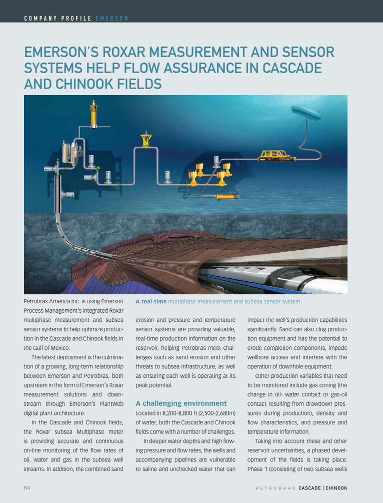
64 P E T R O B R A S CASCADE | CHINOOK
C o m p a n y p r o f i l e e m e r S o n
EmErSON’S rOXAr mEASurEmENT AND SENSOr SySTEmS HElp flOW ASSurANCE IN CASCADE AND CHINOOK fIElDS
PetrobrasAmericaInc.isusingEmerson
Process Management’s integrated Roxar
multiphase measurement and subsea
sensorsystemstohelpoptimizeproduc-
tion in the Cascade and Chinook fields in
the Gulf of Mexico.
The latest deployment is the culmina-
tion of a growing, long-term relationship
between Emerson and Petrobras, both
upstreamintheformofEmerson’sRoxar
measurement solutions and down-
stream through Emerson’s PlantWeb
digital plant architecture.
In the Cascade and Chinook fields,
the Roxar subsea Multiphase meter
is providing accurate and continuous
on-line monitoring of the flow rates of
oil, water and gas in the subsea well
streams. In addition, the combined sand
erosion and pressure and temperature
sensor systems are providing valuable,
real-time production information on the
reservoir, helping Petrobras meet chal-
lenges such as sand erosion and other
threats to subsea infrastructure, as well
as ensuring each well is operating at its
peak potential.
A challenging environmentLocated in 8,200-8,800 ft (2,500-2,680m)
of water, both the Cascade and Chinook
fields come with a number of challenges.
In deeper water depths and high flow-
ing pressure and flow rates, the wells and
accompanying pipelines are vulnerable
to saline and unchecked water that can
impact the well’s production capabilities
significantly. Sand can also clog produc-
tion equipment and has the potential to
erode completion components, impede
wellbore access and interfere with the
operation of downhole equipment.
Otherproductionvariablesthatneed
to be monitored include gas coning (the
change in oil- water contact or gas-oil
contact resulting from drawdown pres-
sures during production), density and
flow characteristics, and pressure and
temperature information.
Taking into account these and other
reservoir uncertainties, a phased devel-
opment of the fields is taking place.
Phase 1 (consisting of two subsea wells
A real-time multiphase measurement and subsea sensor system.
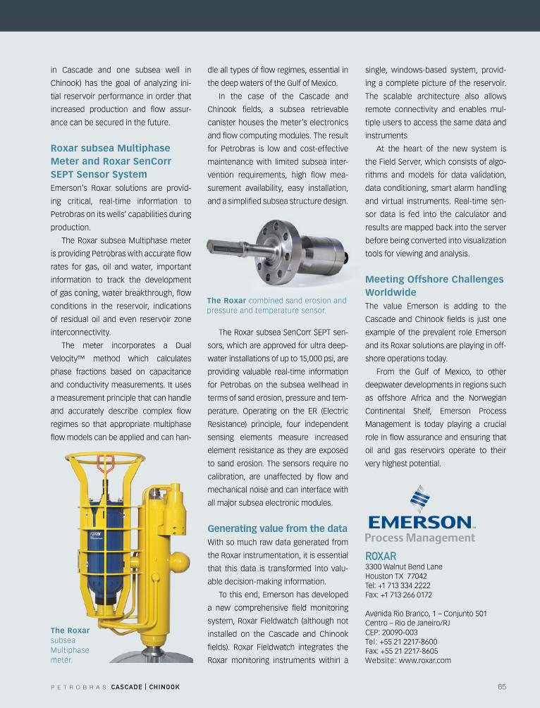
P E T R O B R A S CASCADE | CHINOOK 65
rOXAr3300 Walnut Bend LaneHoustonTX77042Tel: +1 713 334 2222Fax: +1 713 266 0172
Avenida Rio Branco, 1 – Conjunto 501Centro – Rio de Janeiro/RJCEP:20090-003Tel: +55 21 2217-8600Fax: +55 21 2217-8605Website: www.roxar.com
in Cascade and one subsea well in
Chinook) has the goal of analyzing ini-
tial reservoir performance in order that
increased production and flow assur-
ance can be secured in the future.
Roxar subsea Multiphase Meter and Roxar SenCorr SEPT Sensor SystemEmerson’s Roxar solutions are provid-
ing critical, real-time information to
Petrobras on its wells’ capabilities during
production.
The Roxar subsea Multiphase meter
is providing Petrobras with accurate flow
rates for gas, oil and water, important
information to track the development
of gas coning, water breakthrough, flow
conditions in the reservoir, indications
of residual oil and even reservoir zone
interconnectivity.
The meter incorporates a Dual
Velocity™ method which calculates
phase fractions based on capacitance
and conductivity measurements. It uses
a measurement principle that can handle
and accurately describe complex flow
regimes so that appropriate multiphase
flow models can be applied and can han-
dle all types of flow regimes, essential in
the deep waters of the Gulf of Mexico.
In the case of the Cascade and
Chinook fields, a subsea retrievable
canister houses the meter’s electronics
and flow computing modules. The result
for Petrobras is low and cost-effective
maintenance with limited subsea inter-
vention requirements, high flow mea-
surement availability, easy installation,
and a simplified subsea structure design.
TheRoxarsubseaSenCorrSEPTsen-
sors, which are approved for ultra deep-
water installations of up to 15,000 psi, are
providing valuable real-time information
for Petrobas on the subsea wellhead in
terms of sand erosion, pressure and tem-
perature. Operating on the ER (Electric
Resistance) principle, four independent
sensing elements measure increased
element resistance as they are exposed
to sand erosion. The sensors require no
calibration, are unaffected by flow and
mechanical noise and can interface with
all major subsea electronic modules.
Generating value from the data With so much raw data generated from
the Roxar instrumentation, it is essential
that this data is transformed into valu-
able decision-making information.
Tothisend,Emersonhasdeveloped
a new comprehensive field monitoring
system, Roxar Fieldwatch (although not
installed on the Cascade and Chinook
fields). Roxar Fieldwatch integrates the
Roxar monitoring instruments within a
single, windows-based system, provid-
ing a complete picture of the reservoir.
The scalable architecture also allows
remote connectivity and enables mul-
tiple users to access the same data and
instruments
At the heart of the new system is
the Field Server, which consists of algo-
rithms and models for data validation,
data conditioning, smart alarm handling
and virtual instruments. Real-time sen-
sor data is fed into the calculator and
results are mapped back into the server
beforebeingconvertedintovisualization
tools for viewing and analysis.
Meeting Offshore Challenges WorldwideThe value Emerson is adding to the
Cascade and Chinook fields is just one
exampleof theprevalent role Emerson
and its Roxar solutions are playing in off-
shore operations today.
From the Gulf of Mexico, to other
deepwater developments in regions such
as offshore Africa and the Norwegian
Continental Shelf, Emerson Process
Management is today playing a crucial
role in flow assurance and ensuring that
oil and gas reservoirs operate to their
very highest potential.
The Roxar subsea Multiphase meter.
The Roxar combined sand erosion and pressure and temperature sensor.

66 P E T R O B R A S CASCADE | CHINOOK
fmC TECHNOlOGIES prOVIDES NEW SOluTIONS fOr CASCADE AND CHINOOK fIElDSFMC Technologies was awarded a con-
tract by Petrobras America in October
2007 to supply subsea systems for the
operator’s Cascade and Chinook field de-
velopments, which will produce from ul-
tra-deepwater wells targeting the Lower
Tertiary trend in the U.S. Gulf of Mexico.
This development has led to several
industry firsts, including the deployment
of a novel subsea pumping system de-
velopedbyFMCtobeinstalledhorizon-
tally on the seabed.
FMC met the challenges of this proj-
ect by providing the technologies and
solutions to address issues such as the
ultra deepwater depth of up to 8,900
ft, the wide range of variation of flow
and pressure that the pumping system
must accommodate, thermal insulation
and flow assurance requirements, long
offsetdistances to theFPSOanddata
monitoring when the FPSO is discon-
nected.
FMC’s scope of supply included:
• Fourenhancedhorizontalsubsea
trees(EHXT)ratedat15,000psi;
• Three,4-slotmanifolds;
• Twopumpbases;
• Three pump cartridges, each containing
twoelectricalsubmersiblepumps;
• Eightjumpersand16jumperkits;
• Subseacontrolmoduleswithmultiple
electricalandhydraulicmodules;
• SubseaDataAcquisitionSystem
modules;
• TopsidecontrolsincludingMaster
Control Station, subsea power and
communication unit, and radio link
ESDcontrols;
• Mediumvoltagepowersystemwith
variable speed drives and controls
for the subsea pumping system.
Unique, innovative horizontal pumping systemThe Cascade and Chinook pumping sys-
tem is a world’s first. The innovative con-
cept was conceived by Petrobras, with
FMC Technologies developing the original
concept and performing detailed engi-
neering and construction. The unique de-
sign uses electrical submersible pumps
thatareinstalledhorizontallyonthesea-
bed rather than placing the pumps in a
producing well or in a caisson well as is
common in conventional designs.
FMC’s scope of supply included the
specification, design, manufacture and
procurement of all components, as well
as the qualification of the complete sub-
sea pumping system. FMC also specified,
procured and integrated the 6 kV me-
diumvoltage variable speeddrive (VSD)
andVSDmoduleintheFPSO,themedium
voltage connection systems, pumps and
control system.
The subsea pumping system has
several purposes, including to maintain
production flow of hydrocarbons after
the pressure within the wells has de-
clined. The subsea pumping system will
alsomaximizethevolumeofrecovered
reserves and keep the pressure and flow
at the best possible levels for optimum
production and flow assurance.
The horizontal pumping system is
designed for the pumps to be installed
on the seabed and away from the wells.
The system comprises two pump bases,
one for each field, located adjacent to
each drill center and installed in 8,500
and 8,900 ft of water depth, respectively.
Each base accommodates two pump
cartridgesthataremountedhorizontally.
Each90-tonpumpcartridgeincludestwo
850 horsepower electrical submersible
pumps that are capable of pumping up to
20,000 barrels of oil per day from several
wells with a maximum offset distance
of12miles to theFPSO. Thecartridges
also include recirculation loops that allow
operation in a wide range of flow scenarios
andoptimizepumpperformance.
If necessary, the design allows a
pump cartridge to be removed for repair
or replacement without requiring a well
intervention or well shut in to be per-
formed, both of which can potentially
damage a well and reduce potential pro-
ChinookDrillCenterwithtrees,manifoldsandpumpstation
C o m p a n y p r o f i l e f m C T e C h n o l o g i e S
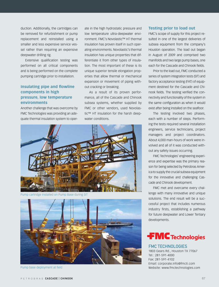
P E T R O B R A S CASCADE | CHINOOK 67
duction. Additionally, the cartridges can
be removed for refurbishment or pump
replacement and reinstalled using a
smaller and less expensive service ves-
sel rather than requiring an expensive
deepwater drilling rig.
Extensive qualification testing was
performed on all critical components
and is being performed on the complete
pumping cartridge prior to installation.
Insulating pipe and flowline components in high pressure, low temperature environmentsAnother challenge that was overcome by
FMC Technologies was providing an ade-
quate thermal insulation system to oper-
ate in the high hydrostatic pressure and
low temperature ultra-deepwater envi-
ronment.FMC’sNovolastic™HTthermal
insulation has proven itself in such oper-
ating environments. Novolastic’s thermal
insulation has unique properties that dif-
ferentiate it from other types of insula-
tion. The most important of these is its
unique superior tensile elongation prop-
erties that allow thermal or mechanical
expansion or movement of piping with-
out cracking or breaking.
As a result of its proven perfor-
mance, all of the Cascade and Chinook
subsea systems, whether supplied by
FMC or other vendors, used Novolas-
tic™HT insulation for the harsh deep-
water conditions.
Testing prior to load outFMC’s scope of supply for this project re-
sulted in one of the largest deliveries of
subsea equipment from the company’s
Houston operation. The load out began
in August of 2009 and comprised two
manifolds and two large pump bases, one
each for the Cascade and Chinook fields.
Prior to the load out, FMC conducted a
series of system integration tests (SIT) and
factory acceptance testing (FAT) of equip-
ment destined for the Cascade and Chi-
nook fields. The testing verified the con-
nectivity and functionality of the system in
the same configuration as when it would
exist after being installed on the seafloor.
The testing involved two phases,
each with a number of steps. Perform-
ing the tests required several installation
engineers, service technicians, project
managers and project coordinators.
About 4,000 man-hours of work were in-
volved and all of it was conducted with-
out any safety issues occurring.
FMC Technologies’ engineering experi-
ence and expertise was the primary rea-
son for being selected by Petrobras Amer-
ica to supply the crucial subsea equipment
for the innovative and challenging Cas-
cade and Chinook development.
FMC met and overcame every chal-
lenge with many innovative and unique
solutions. The end result will be a suc-
cessful project that includes numerous
industry firsts, establishing a pathway
for future deepwater and Lower Tertiary
developments.
fmC TECHNOlOGIES1803GearsRd.,HoustonTX77067Tel.: 281-591-4000Fax: 281-591-4102Email:[email protected]: www.fmctechnologies.comPump base deployment at field
Pump cartridge installed on Pump Base during SIT
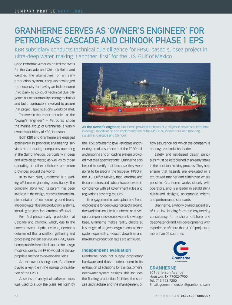
68 P E T R O B R A S CASCADE | CHINOOK
GrANHErNE SErVES AS ‘OWNEr’S ENGINEEr’ fOr pETrOBrAS’ CASCADE AND CHINOOK pHASE 1 EpS
GrANHErNE601 Jefferson AvenueHouston,TX77002-7900Tel: 713 753 7200Email:[email protected]
Once Petrobras America drilled the wells
for the Cascade and Chinook fields and
weighed the alternatives for an early
production system, they acknowledged
the necessity for having an independent
third party to conduct technical due dili-
gence for accountability among technical
and build contractors involved to assure
that project specifications would be met.
To serve in this important role – as the
“owner’s engineer” – Petrobras chose
the marine group of Granherne, a wholly
ownedsubsidiaryofKBR,Houston.
Both KBR and Granherne are engaged
extensively in providing engineering ser-
vices to producing companies operating
in the Gulf of Mexico, particularly in deep
and ultra-deep water, as well as to those
operating in other offshore petroleum
provinces around the world.
In its own right, Granherne is a lead-
ing offshore engineering consultancy. The
company, along with its parent, has been
involved in the design, construction and im-
plementation of numerous ground-break-
ing deepwater floating production systems,
includingprojectsforPetrobrasoffBrazil.
For first-phase early production at
Cascade and Chinook, which, due to the
extreme water depths involved, Petrobras
determined that a seafloor gathering and
processingsystemservinganFPSO,Gran-
herne provided technical support for design
modificationstotheFPSOwouldbetheap-
propriate method to develop the fields.
As the owner’s engineer, Granherne
played a key role in the run-up to installa-
tionoftheFPSO.
A series of analytical software tools
was used to study the plans set forth by
theFPSOprovidertogivePetrobrasanoth-
erdegreeofassurancethattheFPSOhull
and mooring and offloading system provid-
ed met their specifications. Granherne also
helped to certify that because they were
going tobeplacing thefirst-everFPSO in
the U.S. Gulf of Mexico, that Petrobras and
its contractors and subcontractors were in
compliance with all government rules and
regulationscoveringtheEPS.
Its engagement in conceptual and front-
end designs for deepwater projects around
the world has enabled Granherne to devel-
op a comprehensive deepwater knowledge
base. Granherne makes reality checks at
key stages of project design to ensure that
system operability, reduced downtime and
maximum production rates are achieved.
Independent evaluation Granherne does not supply proprietary
hardware and thus is independent in its
evaluation of solutions for the customer’s
deepwater system designs. This includes
the floating production facilities, the sub-
sea architecture and the management of
flow assurance, for which the company is
arecognizedindustryleader.
Safety and risk-based design princi-
ples must be established at an early stage
in the decision-making process. They help
ensure that hazards are evaluated in a
structured manner and eliminated where
possible. Granherne works closely with
operators, and is a leader in establishing
risk-based designs, acceptance criteria
and performance standards.
Granherne, a wholly owned subsidiary
of KBR, is a leading front-end engineering
consultancy for onshore, offshore and
deepwater oil and gas developments with
experience of more than 3,000 projects in
more than 20 countries
KBRsubsidiaryconductstechnicalduediligenceforFPSO-basedsubseaprojectinultra-deep water, making it another ‘first’ for the U.S. Gulf of Mexico
As the owner’s engineer, Granherne provided technical due diligence services to Petrobras indesign,modificationandimplementationoftheFPSOBWPioneerhullandmooringsystem at Cascade and Chinook.
C o m p a n y p r o f i l e g r a n h e r n e
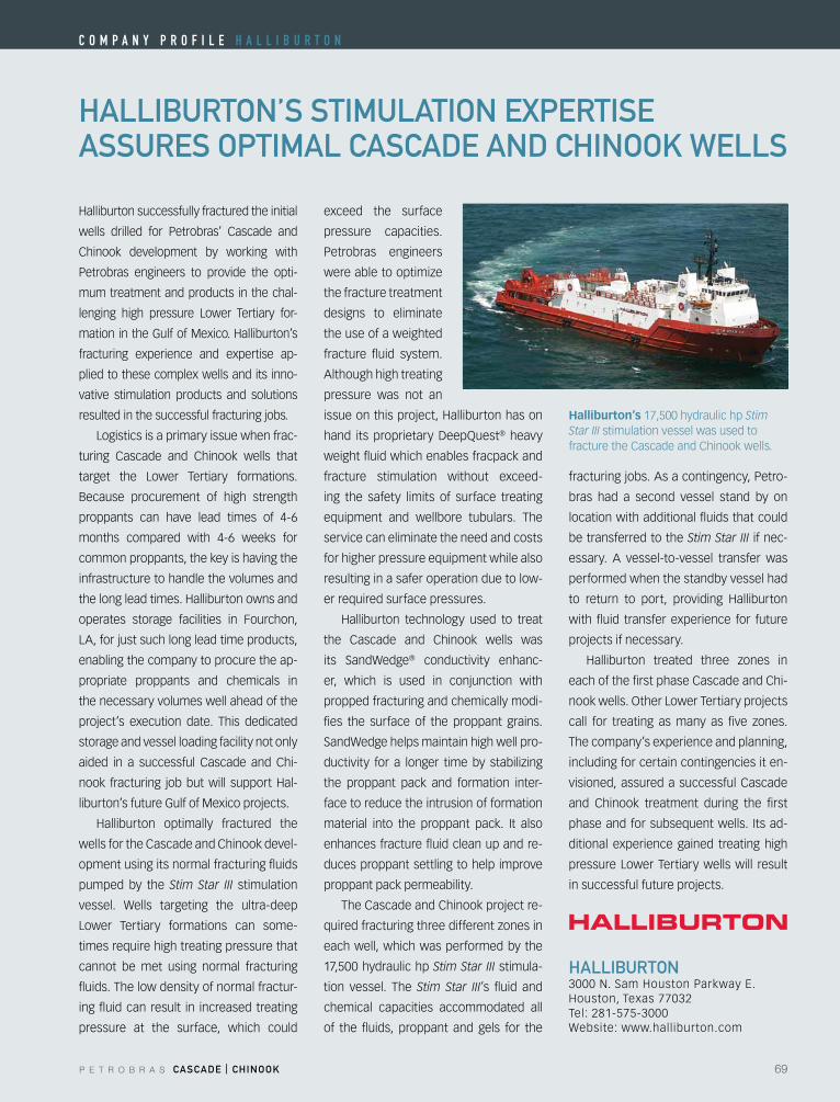
P E T R O B R A S CASCADE | CHINOOK 69
HAllIBurTON’S STImulATION EXpErTISE ASSurES OpTImAl CASCADE AND CHINOOK WEllS
HAllIBurTON3000N.SamHoustonParkwayE.Houston,Texas77032Tel: 281-575-3000Website: www.halliburton.com
Halliburtonsuccessfullyfracturedtheinitial
wells drilled for Petrobras’ Cascade and
Chinook development by working with
Petrobras engineers to provide the opti-
mum treatment and products in the chal-
lenging high pressure Lower Tertiary for-
mationintheGulfofMexico.Halliburton’s
fracturing experience and expertise ap-
plied to these complex wells and its inno-
vative stimulation products and solutions
resulted in the successful fracturing jobs.
Logistics is a primary issue when frac-
turing Cascade and Chinook wells that
target the Lower Tertiary formations.
Because procurement of high strength
proppants can have lead times of 4-6
months compared with 4-6 weeks for
common proppants, the key is having the
infrastructure to handle the volumes and
thelongleadtimes.Halliburtonownsand
operates storage facilities in Fourchon,
LA, for just such long lead time products,
enabling the company to procure the ap-
propriate proppants and chemicals in
the necessary volumes well ahead of the
project’s execution date. This dedicated
storage and vessel loading facility not only
aided in a successful Cascade and Chi-
nook fracturing jobbutwill supportHal-
liburton’s future Gulf of Mexico projects.
Halliburton optimally fractured the
wells for the Cascade and Chinook devel-
opment using its normal fracturing fluids
pumped by the Stim Star III stimulation
vessel. Wells targeting the ultra-deep
Lower Tertiary formations can some-
times require high treating pressure that
cannot be met using normal fracturing
fluids. The low density of normal fractur-
ing fluid can result in increased treating
pressure at the surface, which could
exceed the surface
pressure capacities.
Petrobras engineers
wereabletooptimize
the fracture treatment
designs to eliminate
the use of a weighted
fracture fluid system.
Although high treating
pressure was not an
issueonthisproject,Halliburtonhason
hand its proprietaryDeepQuest® heavy
weight fluid which enables fracpack and
fracture stimulation without exceed-
ing the safety limits of surface treating
equipment and wellbore tubulars. The
service can eliminate the need and costs
for higher pressure equipment while also
resulting in a safer operation due to low-
er required surface pressures.
Halliburton technology used to treat
the Cascade and Chinook wells was
its SandWedge® conductivity enhanc-
er, which is used in conjunction with
propped fracturing and chemically modi-
fies the surface of the proppant grains.
SandWedge helps maintain high well pro-
ductivity for a longer timeby stabilizing
the proppant pack and formation inter-
face to reduce the intrusion of formation
material into the proppant pack. It also
enhances fracture fluid clean up and re-
duces proppant settling to help improve
proppant pack permeability.
The Cascade and Chinook project re-
quiredfracturingthreedifferentzonesin
each well, which was performed by the
17,500 hydraulic hp Stim Star III stimula-
tion vessel. The Stim Star III’s fluid and
chemical capacities accommodated all
of the fluids, proppant and gels for the
fracturing jobs. As a contingency, Petro-
bras had a second vessel stand by on
location with additional fluids that could
be transferred to the Stim Star III if nec-
essary. A vessel-to-vessel transfer was
performed when the standby vessel had
to return to port, providing Halliburton
with fluid transfer experience for future
projects if necessary.
Halliburton treated three zones in
each of the first phase Cascade and Chi-
nookwells.OtherLowerTertiaryprojects
call for treating asmany as five zones.
The company’s experience and planning,
including for certain contingencies it en-
visioned, assured a successful Cascade
and Chinook treatment during the first
phase and for subsequent wells. Its ad-
ditional experience gained treating high
pressure Lower Tertiary wells will result
in successful future projects.
Halliburton’s 17,500 hydraulic hp Stim Star III stimulation vessel was used to fracture the Cascade and Chinook wells.
C o m p a n y p r o f i l e h a l l i B u r T o n
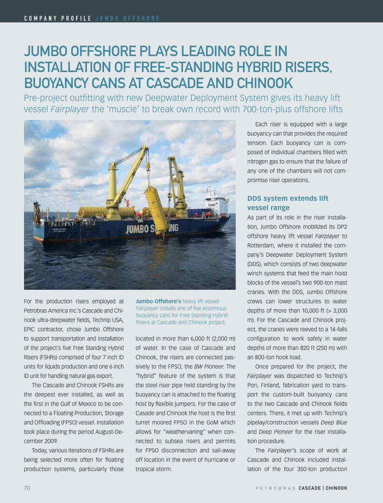
70 P E T R O B R A S CASCADE | CHINOOK
C o m p a n y p r o f i l e J u m B o o f f S h o r e
JumBO OffSHOrE plAyS lEADING rOlE IN INSTAllATION Of frEE-STANDING HyBrID rISErS, BuOyANCy CANS AT CASCADE AND CHINOOK
For the production risers employed at
Petrobras America Inc.’s Cascade and Chi-
nook ultra-deepwater fields, Technip USA,
EPIC contractor, chose Jumbo Offshore
to support transportation and installation
of theproject’s fiveFreeStandingHybrid
Risers(FSHRs)comprisedoffour7inchID
units for liquids production and one 6 inch
IDunitforhandlingnaturalgasexport.
TheCascadeandChinookFSHRsare
the deepest ever installed, as well as
the first in the Gulf of Mexico to be con-
nected to a Floating Production, Storage
andOffloading(FPSO)vessel.Installation
tookplaceduringtheperiodAugust-De-
cember 2009.
Today,variousiterationsofFSHRsare
being selected more often for floating
production systems, particularly those
located in more than 6,000 ft (2,000 m)
of water. In the case of Cascade and
Chinook, the risers are connected pas-
sivelytotheFPSO,theBW Pioneer. The
“hybrid” feature of the system is that
the steel riser pipe held standing by the
buoyancy can is attached to the floating
host by flexible jumpers. For the case of
Casade and Chinook the host is the first
turretmoored FPSO in theGoMwhich
allows for “weathervaning” when con-
nected to subsea risers and permits
for FPSO disconnection and sail-away
off location in the event of hurricane or
tropical storm.
Each riser is equipped with a large
buoyancy can that provides the required
tension. Each buoyancy can is com-
posed of individual chambers filled with
nitrogen gas to ensure that the failure of
any one of the chambers will not com-
promise riser operations.
DDS system extends lift vessel rangeAs part of its role in the riser installa-
tion, JumboOffshoremobilized itsDP2
offshore heavy lift vessel Fairplayer to
Rotterdam, where it installed the com-
pany’s Deepwater Deployment System
(DDS),whichconsistsoftwodeepwater
winch systems that feed the main hoist
blocks of the vessel’s two 900-ton mast
cranes. With the DDS, Jumbo Offshore
crews can lower structures to water
depths of more than 10,000 ft (> 3,000
m). For the Cascade and Chinook proj-
ect, the cranes were reeved to a 14-falls
configuration to work safely in water
depths of more than 820 ft (250 m) with
an 800-ton hook load.
Once prepared for the project, the
Fairplayer was dispatched to Technip’s
Pori, Finland, fabrication yard to trans-
port the custom-built buoyancy cans
to the two Cascade and Chinook fields
centers. There, it met up with Technip’s
pipelay/construction vessels Deep Blue
and Deep Pioneer for the riser installa-
tion procedure.
The Fairplayer’s scope of work at
Cascade and Chinook included instal-
lation of the four 350-ton production
Jumbo Offshore’s heavy lift vessel Fairplayer installs one of five enormous buoyancycansforFreeStandingHybridRisers at Cascade and Chinook project.
Pre-projectoutfittingwithnewDeepwaterDeploymentSystemgivesitsheavyliftvessel Fairplayer the ‘muscle’ to break own record with 700-ton-plus offshore lifts
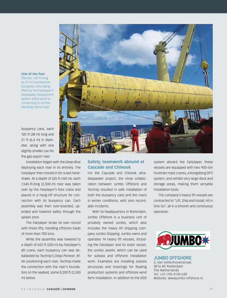
P E T R O B R A S CASCADE | CHINOOK 71
JumBO OffSHOrE3, Van Vollenhovenstraat3016BERotterdamThe NetherlandsTel: +31 (10) 4134 630Website: wwwjumbo-offshore.nl
buoyancy cans, each
125 ft (38 m) long and
21 ft (6.4 m) in diam-
eter, along with one
slightly smaller can for
the gas export riser.
Installation began with the Deep Blue
deploying each riser in its entirety. The
Fairplayer then moved in for a wet hand-
shake. At a depth of 525 ft (160 m), each
7,545-ft-long (2,300-m) riser was taken
over by the Fairplayer’s fore crane and
placed in a hang-off structure for con-
nection with its buoyancy can. Each
assembly was then over-boarded, up-
ended and lowered safely through the
splashzone.
The Fairplayer broke its own record
with these lifts, handling offshore loads
of more than 700 tons.
While the assembly was lowered to
a depth of 655 ft (200 m) by Fairplayer’s
aft crane, each buoyancy can was de-
ballasted by Technip’s Deep Pioneer. Af-
ter positioning each riser, Technip made
the connection with the riser’s founda-
tion on the seabed, some 8,200 ft (2,500
m) below.
Safety, teamwork abound at Cascade and Chinook For the Cascade and Chinook ultra-
deepwater project, the close collabo-
ration between Jumbo Offshore and
Technip resulted in safe installation of
both the buoyancy cans and the risers
inwinter conditions,with zero record-
able incidents.
With its headquarters in Rotterdam,
Jumbo Offshore is a business unit of
privately owned Jumbo, which also
includes the heavy lift shipping com-
pany Jumbo Shipping. Jumbo owns and
operates 14 heavy lift vessels, includ-
ing the Fairplayer and its sister vessel,
the Jumbo Javelin, which can be used
for subsea and offshore installation
work. Examples are installing subsea
structures and moorings for floating
production systems and offshore wind
farminstallation.InadditiontotheDDS
system aboard the Fairplayer, these
vessels are equipped with two 900-ton
Huismanmastcranes,aKongsbergDP2
system, and exhibit very large deck and
storage areas, making them versatile
installation tools.
The company’s heavy lift vessels are
contracted to “Lift, Ship and Install, All in
OneGo”,allinasmoothandcontinuous
operation.
One of the four 350-ton, 125-ft-long by21-ft-Dproductionbuoyancy cans being lifted by the Fairplayer’s DeepwaterDeploymentSystem(DDS)priortoconnecting to its free-standing hybrid riser.
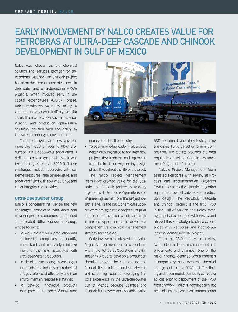
72 P E T R O B R A S CASCADE | CHINOOK
C o m p a n y p r o f i l e n a l C o
EArly INVOlVEmENT By NAlCO CrEATES VAluE fOr pETrOBrAS AT ulTrA-DEEp CASCADE AND CHINOOK DEVElOpmENT IN Gulf Of mEXICONalco was chosen as the chemical
solution and services provider for the
Petrobras Cascade and Chinook project
based on their track record of success in
deepwater and ultra-deepwater (UDW)
projects. When involved early in the
capital expenditures (CAPEX) phase,
Nalco maximizes value by taking a
comprehensive view of the life cycle of the
asset. This includes flow assurance, asset
integrity and production optimization
solutions; coupled with the ability to
innovate in challenging environments.
The most significant new environ-
ment the industry faces is UDW pro-
duction. Ultra-deepwater production is
defined as oil and gas production in wa-
ter depths greater than 5000 ft. These
challenges include reservoirs with ex-
treme pressures, high temperature, and
produced fluids with flow assurance and
asset integrity complexities.
Ultra-Deepwater GroupNalco is concentrating fully on the new
challenges associated with deep and
ultra-deepwater operations and formed
a dedicated Ultra-Deepwater Group,
whose focus is:
• To work closely with production and
engineering companies to identify,
understand, and ultimately minimize
many of the risks associated with
ultra-deepwater production.
• To develop cutting-edge technologies
that enable the industry to produce oil
and gas safely, cost-effectively, and in an
environmentally responsible manner.
• To develop innovative products
that provide an order-of-magnitude
improvement to the industry.
• Tobeaknowledgeleaderinultra-deep
water, allowing Nalco to facilitate new
project development and operation
from the front-end engineering design
phase throughout the life of the asset.
The Nalco Project Management
Team have created value for the Cas-
cade and Chinook project by working
togetherwithPetrobrasOperationsand
Engineeringteamsfromtheprojectde-
sign stage. In the past, chemical suppli-
ers were brought into a project just prior
to production start-up, which can result
in missed opportunities to develop a
comprehensive chemical management
strategy for the asset.
Early involvement allowed the Nalco
Project Management team to work close-
lywiththePetrobrasOperationsandEn-
gineering group to develop a production
chemical program for the Cascade and
Chinook fields. Initial chemical selection
and screening required leveraging Na-
lco’s experience in the ultra-deepwater
Gulf of Mexico because Cascade and
Chinook fluids were not available. Nalco
R&Dperformed laboratory testingusing
analogous fluids based on similar com-
position. The testing provided the data
required to develop a Chemical Manage-
ment Program for Petrobras.
Nalco’s Project Management Team
assisted Petrobras with reviewing Pro-
cess and Instrumentation Diagrams
(P&ID) related to thechemical injection
equipment, overall subsea and produc-
tion design. The Petrobras Cascade
and Chinook project is the first FPSO
in the Gulf of Mexico and Nalco lever-
agedglobalexperiencewithFPSOsand
utilizedthisknowledgetoshareexperi-
ences with Petrobras and incorporate
lessons learned into the project.
From the P&ID and system review,
Nalco identified and recommended im-
provements and changes. One of the
major findings identified was a materials
incompatibility issue with the chemical
storagetanks in theFPSOhull.Thisfind-
ing and recommendation led to corrective
actionsprior todeploymentof theFPSO
fromdrydock.Hadthisincompatibilitynot
been discovered, chemical contamination
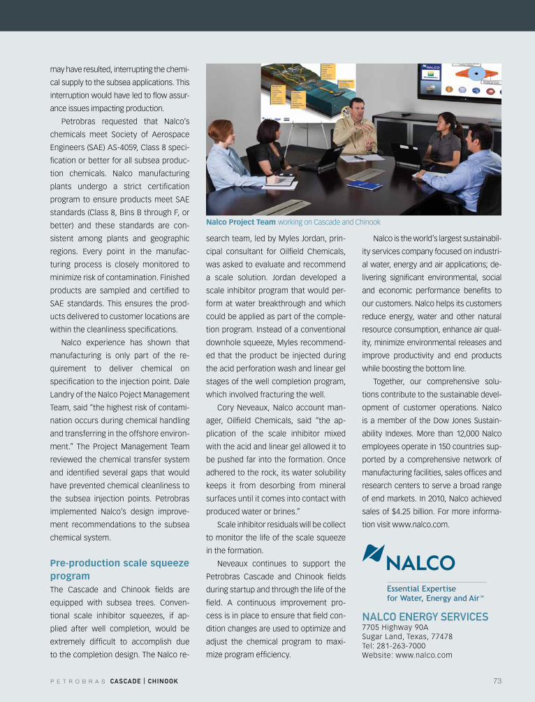
P E T R O B R A S CASCADE | CHINOOK 73
Essential Expertise for Water, Energy and Air SM
NAlCO ENErGy SErVICES 7705Highway90A Sugar Land, Texas, 77478 Tel: 281-263-7000 Website: www.nalco.com
may have resulted, interrupting the chemi-
cal supply to the subsea applications. This
interruption would have led to flow assur-
ance issues impacting production.
Petrobras requested that Nalco’s
chemicals meet Society of Aerospace
Engineers(SAE)AS-4059,Class8speci-
fication or better for all subsea produc-
tion chemicals. Nalco manufacturing
plants undergo a strict certification
program toensureproductsmeetSAE
standards (Class 8, Bins B through F, or
better) and these standards are con-
sistent among plants and geographic
regions. Every point in the manufac-
turing process is closely monitored to
minimizeriskofcontamination.Finished
products are sampled and certified to
SAE standards. This ensures the prod-
ucts delivered to customer locations are
within the cleanliness specifications.
Nalco experience has shown that
manufacturing is only part of the re-
quirement to deliver chemical on
specificationtotheinjectionpoint.Dale
Landry of the Nalco Poject Management
Team, said “the highest risk of contami-
nation occurs during chemical handling
and transferring in the offshore environ-
ment.” The Project Management Team
reviewed the chemical transfer system
and identified several gaps that would
have prevented chemical cleanliness to
the subsea injection points. Petrobras
implemented Nalco’s design improve-
ment recommendations to the subsea
chemical system.
Pre-production scale squeeze programThe Cascade and Chinook fields are
equipped with subsea trees. Conven-
tional scale inhibitor squeezes, if ap-
plied after well completion, would be
extremely difficult to accomplish due
to the completion design. The Nalco re-
search team, led by Myles Jordan, prin-
cipal consultant for Oilfield Chemicals,
was asked to evaluate and recommend
a scale solution. Jordan developed a
scale inhibitor program that would per-
form at water breakthrough and which
could be applied as part of the comple-
tion program. Instead of a conventional
downholesqueeze,Mylesrecommend-
ed that the product be injected during
the acid perforation wash and linear gel
stages of the well completion program,
which involved fracturing the well.
Cory Neveaux, Nalco account man-
ager, Oilfield Chemicals, said “the ap-
plication of the scale inhibitor mixed
with the acid and linear gel allowed it to
bepushedfarintotheformation.Once
adhered to the rock, its water solubility
keeps it from desorbing from mineral
surfaces until it comes into contact with
produced water or brines.”
Scale inhibitor residuals will be collect
tomonitorthelifeofthescalesqueeze
in the formation.
Neveaux continues to support the
Petrobras Cascade and Chinook fields
during startup and through the life of the
field. A continuous improvement pro-
cess is in place to ensure that field con-
ditionchangesareusedtooptimizeand
adjust the chemical program to maxi-
mizeprogramefficiency.
Nalco is the world’s largest sustainabil-
ity services company focused on industri-
alwater,energyandairapplications;de-
livering significant environmental, social
and economic performance benefits to
our customers. Nalco helps its customers
reduce energy, water and other natural
resource consumption, enhance air qual-
ity,minimizeenvironmentalreleasesand
improve productivity and end products
while boosting the bottom line.
Together, our comprehensive solu-
tions contribute to the sustainable devel-
opment of customer operations. Nalco
is amemberof theDow JonesSustain-
ability Indexes. More than 12,000 Nalco
employees operate in 150 countries sup-
ported by a comprehensive network of
manufacturing facilities, sales offices and
research centers to serve a broad range
of end markets. In 2010, Nalco achieved
sales of $4.25 billion. For more informa-
tion visit www.nalco.com.
Nalco Project Team working on Cascade and Chinook
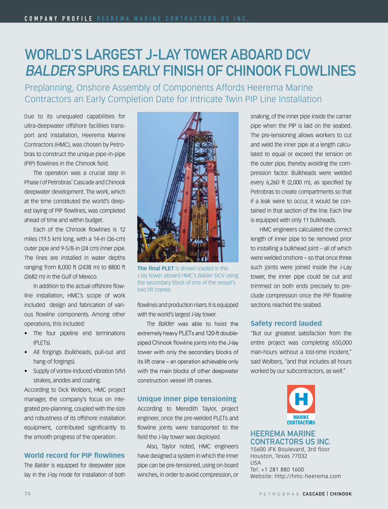
74 P E T R O B R A S CASCADE | CHINOOK
C o m p a n y p r o f i l e h e e r e m a m a r i n e C o n T r a C T o r S u S i n C .
WOrlD’S lArGEST J-lAy TOWEr ABOArD DCV BAlDEr SpurS EArly fINISH Of CHINOOK flOWlINES
HEErEmA mArINECONTrACTOrS uS INC.15600 JFK Boulevard, 3rd floorHouston,Texas77032USATel: +1 281 880 1600Website: http://hmc-heerema.com
Due to its unequaled capabilities for
ultra-deepwater offshore facilities trans-
port and installation, Heerema Marine
Contractors(HMC),waschosenbyPetro-
bras to construct the unique pipe-in-pipe
(PIP) flowlines in the Chinook field.
The operation was a crucial step in
Phase I of Petrobras’ Cascade and Chinook
deepwater development. The work, which
at the time constituted the world’s deep-
est laying of PIP flowlines, was completed
ahead of time and within budget.
Each of the Chinook flowlines is 12
miles (19.5 km) long, with a 14-in (36-cm)
outer pipe and 9-5/8-in (24 cm) inner pipe.
The lines are installed in water depths
ranging from 8,000 ft (2438 m) to 8800 ft
(2682 m) in the Gulf of Mexico.
In addition to the actual offshore flow-
line installation, HMC’s scope of work
included design and fabrication of vari-
ous flowline components. Among other
operations, this included:
• The four pipeline end terminations
(PLETs).
• All forgings (bulkheads, pull-out and
hang-of forgings).
• Supplyofvortex-inducedvibration(VIV)
strakes, anodes and coating.
According toDickWolbers,HMCproject
manager, the company’s focus on inte-
gratedpre-planning,coupledwiththesize
and robustness of its offshore installation
equipment, contributed significantly to
the smooth progress of the operation.
World record for PIP flowlinesThe Balder is equipped for deepwater pipe
lay in the J-lay mode for installation of both
flowlines and production risers. It is equipped
with the world’s largest J-lay tower.
The Balder was able to hoist the
extremely heavy PLETs and 120-ft double-
piped Chinook flowline joints into the J-lay
tower with only the secondary blocks of
its lift crane – an operation achievable only
with the main blocks of other deepwater
construction vessel lift cranes.
Unique inner pipe tensioning According to Meredith Taylor, project
engineer,oncethepre-weldedPLETsand
flowline joints were transported to the
field the J-lay tower was deployed.
Also, Taylor noted, HMC engineers
have designed a system in which the inner
pipe can be pre-tensioned, using on-board
winches, in order to avoid compression, or
snaking, of the inner pipe inside the carrier
pipe when the PIP is laid on the seabed.
The pre-tensioning allows workers to cut
and weld the inner pipe at a length calcu-
lated to equal or exceed the tension on
the outer pipe, thereby avoiding the com-
pression factor. Bulkheads were welded
every 6,260 ft (2,000 m), as specified by
Petrobras to create compartments so that
if a leak were to occur, it would be con-
tainedinthatsectionoftheline.Eachline
is equipped with only 11 bulkheads.
HMCengineerscalculatedthecorrect
length of inner pipe to be removed prior
to installing a bulkhead joint – all of which
were welded onshore – so that once three
such joints were joined inside the J-Lay
tower, the inner pipe could be cut and
trimmed on both ends precisely to pre-
clude compression once the PIP flowline
sections reached the seabed.
Safety record lauded“But our greatest satisfaction from the
entire project was completing 650,000
man-hours without a lost-time incident,”
said Wolbers, “and that includes all hours
worked by our subcontractors, as well.”
Preplanning,OnshoreAssemblyofComponentsAffordsHeeremaMarineContractorsanEarlyCompletionDateforIntricateTwinPIPLineInstallation
The final PLET is shown loaded in the J-laytoweraboardHMC’sBalderDCVusingthe secondary block of one of the vessel’s two lift cranes.
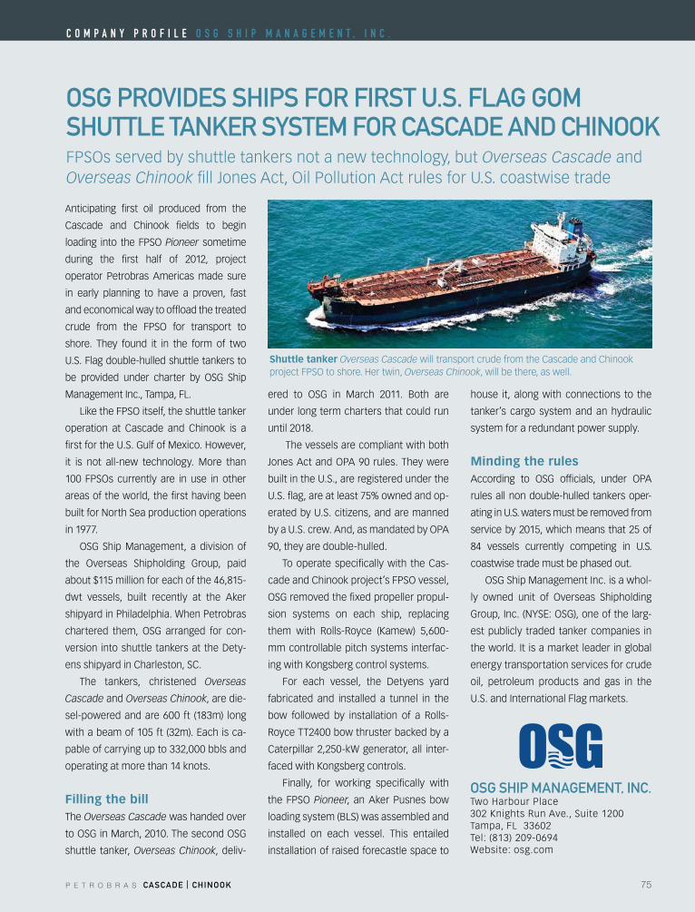
P E T R O B R A S CASCADE | CHINOOK 75
OSG prOVIDES SHIpS fOr fIrST u.S. flAG GOm SHuTTlE TANKEr SySTEm fOr CASCADE AND CHINOOK
OSG SHIp mANAGEmENT, INC.TwoHarbourPlace302 Knights Run Ave., Suite 1200Tampa, FL 33602Tel: (813) 209-0694Website: osg.com
Anticipating first oil produced from the
Cascade and Chinook fields to begin
loading into theFPSOPioneer sometime
during the first half of 2012, project
operator Petrobras Americas made sure
in early planning to have a proven, fast
and economical way to offload the treated
crude from the FPSO for transport to
shore. They found it in the form of two
U.S. Flag double-hulled shuttle tankers to
be provided under charter by OSG Ship
Management Inc., Tampa, FL.
LiketheFPSOitself,theshuttletanker
operation at Cascade and Chinook is a
firstfortheU.S.GulfofMexico.However,
it is not all-new technology. More than
100 FPSOs currently are in use in other
areas of the world, the first having been
built for North Sea production operations
in 1977.
OSG ShipManagement, a division of
the Overseas Shipholding Group, paid
about $115 million for each of the 46,815-
dwt vessels, built recently at the Aker
shipyard in Philadelphia. When Petrobras
chartered them, OSG arranged for con-
version intoshuttle tankersat theDety-
ens shipyard in Charleston, SC.
The tankers, christened Overseas
Cascade and Overseas Chinook, are die-
sel-powered and are 600 ft (183m) long
withabeamof105ft(32m).Eachisca-
pable of carrying up to 332,000 bbls and
operating at more than 14 knots.
Filling the billThe Overseas Cascade was handed over
toOSGinMarch,2010.ThesecondOSG
shuttle tanker, Overseas Chinook, deliv-
ered to OSG in March 2011. Both are
under long term charters that could run
until 2018.
The vessels are compliant with both
JonesActandOPA90rules.Theywere
built in the U.S., are registered under the
U.S. flag, are at least 75% owned and op-
eratedbyU.S.citizens,andaremanned
byaU.S.crew.And,asmandatedbyOPA
90, they are double-hulled.
To operate specifically with the Cas-
cadeandChinookproject’sFPSOvessel,
OSGremovedthefixedpropellerpropul-
sion systems on each ship, replacing
them with Rolls-Royce (Kamew) 5,600-
mm controllable pitch systems interfac-
ing with Kongsberg control systems.
For each vessel, the Detyens yard
fabricated and installed a tunnel in the
bow followed by installation of a Rolls-
Royce TT2400 bow thruster backed by a
Caterpillar 2,250-kW generator, all inter-
faced with Kongsberg controls.
Finally, for working specifically with
the FPSOPioneer, an Aker Pusnes bow
loading system (BLS) was assembled and
installed on each vessel. This entailed
installation of raised forecastle space to
house it, along with connections to the
tanker’s cargo system and an hydraulic
system for a redundant power supply.
Minding the rulesAccording to OSG officials, under OPA
rules all non double-hulled tankers oper-
ating in U.S. waters must be removed from
service by 2015, which means that 25 of
84 vessels currently competing in U.S.
coastwise trade must be phased out.
OSGShipManagementInc.isawhol-
ly owned unit of Overseas Shipholding
Group,Inc.(NYSE:OSG),oneofthelarg-
est publicly traded tanker companies in
the world. It is a market leader in global
energy transportation services for crude
oil, petroleum products and gas in the
U.S. and International Flag markets.
FPSOsservedbyshuttletankersnotanewtechnology,butOverseas Cascade and Overseas ChinookfillJonesAct,OilPollutionActrulesforU.S.coastwisetrade
Shuttle tanker Overseas Cascade will transport crude from the Cascade and Chinook projectFPSOtoshore.Hertwin,Overseas Chinook, will be there, as well.
C o m p a n y p r o f i l e o S g S h i p m a n a g e m e n T , i n C .
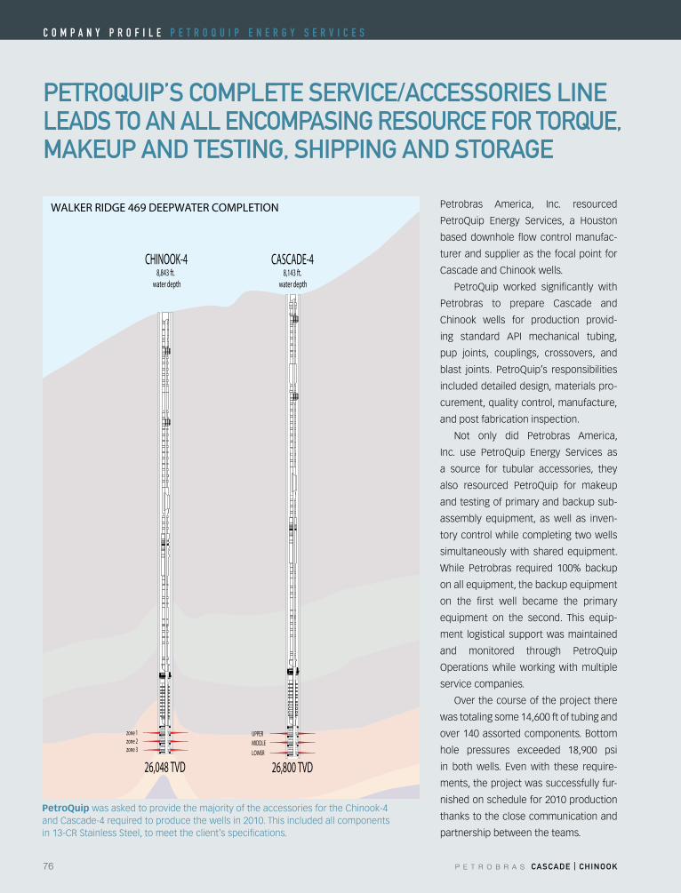
76 P E T R O B R A S CASCADE | CHINOOK
C o m p a n y p r o f i l e p e T r o Q u i p e n e r g y S e r V i C e S
pETrOQuIp’S COmplETE SErVICE/ACCESSOrIES lINElEADS TO AN All ENCOmpASING rESOurCE fOr TOrQuE,mAKEup AND TESTING, SHIppING AND STOrAGE
Petrobras America, Inc. resourced
PetroQuip Energy Services, a Houston
based downhole flow control manufac-
turer and supplier as the focal point for
Cascade and Chinook wells.
PetroQuip worked significantly with
Petrobras to prepare Cascade and
Chinook wells for production provid-
ing standard API mechanical tubing,
pup joints, couplings, crossovers, and
blast joints. PetroQuip’s responsibilities
included detailed design, materials pro-
curement, quality control, manufacture,
and post fabrication inspection.
Not only did Petrobras America,
Inc. use PetroQuip Energy Services as
a source for tubular accessories, they
also resourced PetroQuip for makeup
and testing of primary and backup sub-
assembly equipment, as well as inven-
tory control while completing two wells
simultaneously with shared equipment.
While Petrobras required 100% backup
on all equipment, the backup equipment
on the first well became the primary
equipment on the second. This equip-
ment logistical support was maintained
and monitored through PetroQuip
Operationswhileworkingwithmultiple
service companies.
Overthecourseoftheprojectthere
was totaling some 14,600 ft of tubing and
over 140 assorted components. Bottom
hole pressures exceeded 18,900 psi
in bothwells. Evenwith these require-
ments, the project was successfully fur-
nished on schedule for 2010 production
thanks to the close communication and
partnership between the teams.
PetroQuip was asked to provide the majority of the accessories for the Chinook-4 and Cascade-4 required to produce the wells in 2010. This included all components in 13-CR Stainless Steel, to meet the client’s specifications.
CHINOOK-48,843 ft.
water depth
26,048 TVD
zone 2zone 3
zone 1
CASCADE-4
MIDDLEUPPER
LOWER
8,143 ft. water depth
26,800 TVD
WALKER RIDGE 469 DEEPWATER COMPLETION
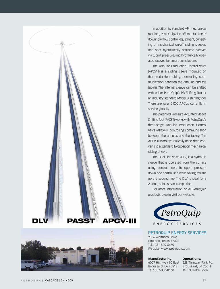
P E T R O B R A S CASCADE | CHINOOK 77
In addition to standard API mechanical
tubulars,PetroQuipalsooffersafulllineof
downhole flow control equipment, consist-
ing of mechanical on/off sliding sleeves,
one shot hydraulically actuated sleeves
via tubing pressure, and hydraulically oper-
ated sleeves for smart completions.
The Annular Production Control Valve
(APCV-II) is a sliding sleeve mounted on
the production tubing, controlling com-
munication between the annulus and the
tubing. The internal sleeve can be shifted
witheitherPetroQuip’sPBShiftingToolor
an industry standard Model B shifting tool.
There are over 2,000 APCVs currently in
service globally.
The patented Pressure Actuated Sleeve
ShiftingTool(PASST)workswithPetroQuip’s
three-stage Annular Production Control
Valve (APCV-III) controlling communication
between the annulus and the tubing. The
APCV-III shifts hydraulically once, then con-
verts to a standard twoposition mechanical
sliding sleeve.
TheDualLineValve(DLV)isahydraulic
sleeve that is operated from the surface
using control lines. To open, pressure
down one control line while taking returns
upthesecond line.TheDLV is ideal fora
2-zone,3-linesmartcompletion.
FormoreinformationonallPetroQuip
products, please visit our website.
pETrOQuIp ENErGy SErVICES 9806WhithornDriveHouston,Texas77095Tel.: 281-500-8430Website: www.petroquip.com
Manufacturing:6007Highway90EastBroussard, LA 70518Tel.: 337-330-8160
Operations:228 Thruway Park Rd.Broussard, LA 70518Tel.: 337-839-2587
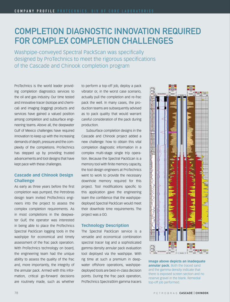
78 P E T R O B R A S CASCADE | CHINOOK
C o m p a n y p r o f i l e p r o T e C h n i C S , D i V o f C o r e l a B o r a T o r i e S
COmplETION DIAGNOSTIC INNOVATION rEQuIrED fOr COmplEX COmplETION CHAllENGES
to perform a top-off job, deploy a pack
vibrator or, in the worst case scenario,
actually pull the completion and re-frac
pack the well. In many cases, the pro-
duction teams are subsequently advised
as to pack quality that would warrant
careful consideration of the pack during
production.
Subsurface completion designs in the
Cascade and Chinook project added a
new challenge: how to obtain this vital
completion diagnostic information in a
complex multi-stage single trip opera-
tion. Because the Spectral PackScan is a
memory tool with finite memory capacity,
the tool design engineers at ProTechnics
went to work to provide the necessary
downhole memory required for this
project. Tool modifications specific to
this application gave the engineering
team the confidence that the washpipe-
deployed Spectral PackScan would meet
their downhole time requirements. The
projectwasaGO.
Technology Description The Spectral PackScan service is a
versatile and economical combination
spectral tracer log and a sophisticated
gamma density annular pack evaluation
tool deployed via the washpipe. With
rig time at such a premium in deep-
water offshore operations, washpipe-
deployed tools are best-in-class decision
points. During the frac pack operation,
ProTechnics SpectraStim gamma tracers
Washpipe-conveyed Spectral PackScan was specifically designed by ProTechnics to meet the rigorous specifications of the Cascade and Chinook completion program
ProTechnics is the world leader provid-
ing completion diagnostics services to
theoilandgasindustry.Ourtimetested
and innovative tracer (isotope and chemi-
cal) and imaging (logging) products and
services have gained a valued position
among completion and subsurface engi-
neering teams. Above all, the deepwater
Gulf of Mexico challenges have required
innovation to keep up with the increasing
demands of depth, pressure and the com-
plexity of the completions. ProTechnics
has stepped up by providing trusted
advancements and tool designs that have
kept pace with these challenges.
Cascade and Chinook Design ChallengeAs early as three years before the first
completion was pumped, the Petrobras
design team invited ProTechnics engi-
neers into the project to assess the
complex completion requirements. As
in most completions in the deepwa-
ter Gulf, the operator was interested
in being able to place the ProTechnics
Spectral PackScan logging tools in the
washpipe for economical and timely
assessment of the frac pack operation.
With ProTechnics technology on board,
the engineering team had the unique
ability to assess the quality of the frac
and, more importantly, the integrity of
the annular pack. Armed with this infor-
mation, critical go-forward decisions
are routinely made, such as whether
Image above depicts an inadequate annular pack. Both the traced sand and the gamma density indicate that there is exposed screen section and no reserve gravel in the blank. Remedial top-off job performed.
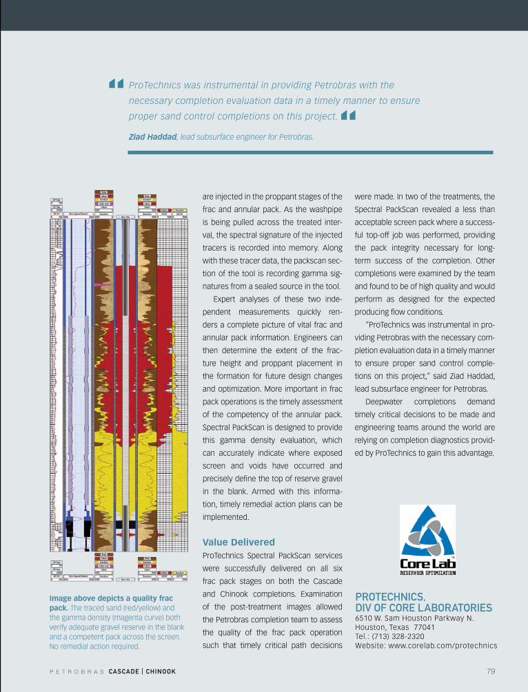
P E T R O B R A S CASCADE | CHINOOK 79
prOTECHNICS, DIV Of COrE lABOrATOrIES6510W.SamHoustonParkwayN.Houston,Texas77041Tel.: (713) 328-2320Website: www.corelab.com/protechnics
Image above depicts a quality frac pack. The traced sand (red/yellow) and the gamma density (magenta curve) both verify adequate gravel reserve in the blank and a competent pack across the screen. No remedial action required.
ProTechnics was instrumental in providing Petrobras with the
necessary completion evaluation data in a timely manner to ensure
proper sand control completions on this project. Ziad Haddad, lead subsurface engineer for Petrobras.
“ “are injected in the proppant stages of the
frac and annular pack. As the washpipe
is being pulled across the treated inter-
val, the spectral signature of the injected
tracers is recorded into memory. Along
with these tracer data, the packscan sec-
tion of the tool is recording gamma sig-
natures from a sealed source in the tool.
Expert analyses of these two inde-
pendent measurements quickly ren-
ders a complete picture of vital frac and
annularpack information.Engineerscan
then determine the extent of the frac-
ture height and proppant placement in
the formation for future design changes
andoptimization.More important in frac
pack operations is the timely assessment
of the competency of the annular pack.
Spectral PackScan is designed to provide
this gamma density evaluation, which
can accurately indicate where exposed
screen and voids have occurred and
precisely define the top of reserve gravel
in the blank. Armed with this informa-
tion, timely remedial action plans can be
implemented.
Value DeliveredProTechnics Spectral PackScan services
were successfully delivered on all six
frac pack stages on both the Cascade
and Chinook completions. Examination
of the post-treatment images allowed
the Petrobras completion team to assess
the quality of the frac pack operation
such that timely critical path decisions
were made. In two of the treatments, the
Spectral PackScan revealed a less than
acceptable screen pack where a success-
ful top-off job was performed, providing
the pack integrity necessary for long-
term success of the completion. Other
completions were examined by the team
and found to be of high quality and would
perform as designed for the expected
producing flow conditions.
“ProTechnics was instrumental in pro-
viding Petrobras with the necessary com-
pletion evaluation data in a timely manner
to ensure proper sand control comple-
tions on this project,” said ZiadHaddad,
lead subsurface engineer for Petrobras.
Deepwater completions demand
timely critical decisions to be made and
engineering teams around the world are
relying on completion diagnostics provid-
ed by ProTechnics to gain this advantage.
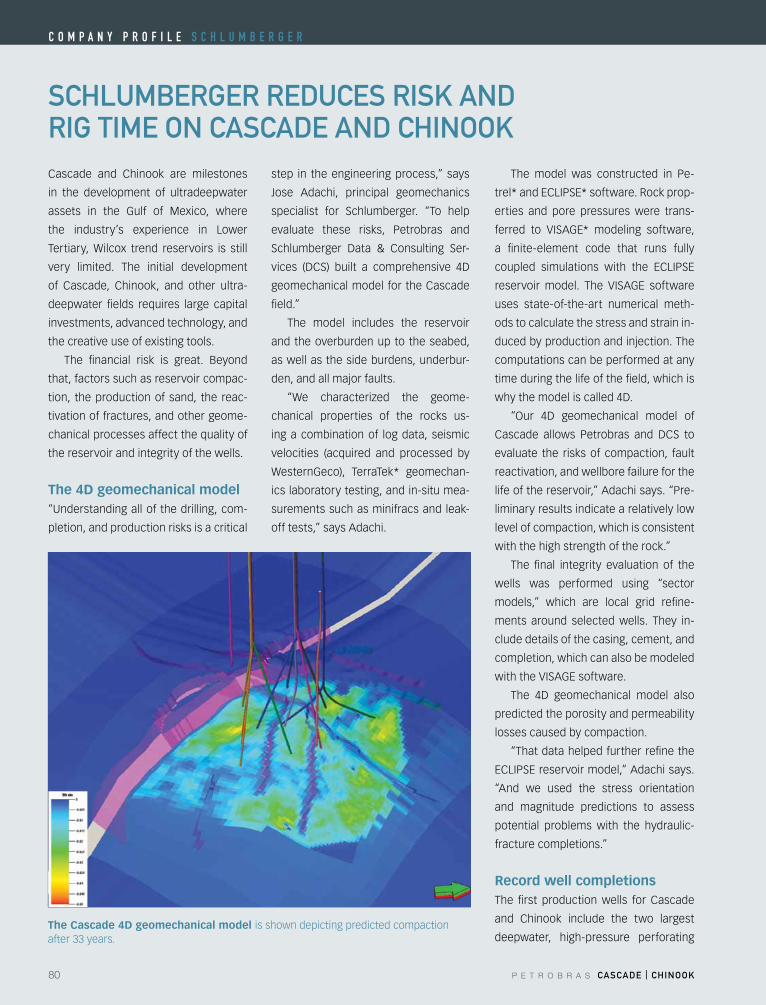
80 P E T R O B R A S CASCADE | CHINOOK
C o m p a n y p r o f i l e S C h l u m B e r g e r
SCHlumBErGEr rEDuCES rISK AND rIG TImE ON CASCADE AND CHINOOKCascade and Chinook are milestones
in the development of ultradeepwater
assets in the Gulf of Mexico, where
the industry’s experience in Lower
Tertiary, Wilcox trend reservoirs is still
very limited. The initial development
of Cascade, Chinook, and other ultra-
deepwater fields requires large capital
investments, advanced technology, and
the creative use of existing tools.
The financial risk is great. Beyond
that, factors such as reservoir compac-
tion, the production of sand, the reac-
tivation of fractures, and other geome-
chanical processes affect the quality of
the reservoir and integrity of the wells.
The 4D geomechanical model“Understanding all of the drilling, com-
pletion, and production risks is a critical
step in the engineering process,” says
Jose Adachi, principal geomechanics
specialist for Schlumberger. “To help
evaluate these risks, Petrobras and
Schlumberger Data & Consulting Ser-
vices (DCS) built a comprehensive 4D
geomechanical model for the Cascade
field.”
The model includes the reservoir
and the overburden up to the seabed,
as well as the side burdens, underbur-
den, and all major faults.
“We characterized the geome-
chanical properties of the rocks us-
ing a combination of log data, seismic
velocities (acquired and processed by
WesternGeco), TerraTek* geomechan-
ics laboratory testing, and in-situ mea-
surements such as minifracs and leak-
off tests,” says Adachi.
The model was constructed in Pe-
trel*andECLIPSE*software.Rockprop-
erties and pore pressures were trans-
ferred to VISAGE* modeling software,
a finite-element code that runs fully
coupled simulations with the ECLIPSE
reservoir model. The VISAGE software
uses state-of-the-art numerical meth-
ods to calculate the stress and strain in-
duced by production and injection. The
computations can be performed at any
time during the life of the field, which is
whythemodeliscalled4D.
“Our 4D geomechanical model of
Cascade allows Petrobras and DCS to
evaluate the risks of compaction, fault
reactivation, and wellbore failure for the
life of the reservoir,” Adachi says. “Pre-
liminary results indicate a relatively low
level of compaction, which is consistent
with the high strength of the rock.”
The final integrity evaluation of the
wells was performed using “sector
models,” which are local grid refine-
ments around selected wells. They in-
clude details of the casing, cement, and
completion, which can also be modeled
withtheVISAGEsoftware.
The 4D geomechanical model also
predicted the porosity and permeability
losses caused by compaction.
“That data helped further refine the
ECLIPSEreservoirmodel,”Adachisays.
“And we used the stress orientation
and magnitude predictions to assess
potential problems with the hydraulic-
fracture completions.”
Record well completionsThe first production wells for Cascade
and Chinook include the two largest
deepwater, high-pressure perforating The Cascade 4D geomechanical model is shown depicting predicted compaction after 33 years.
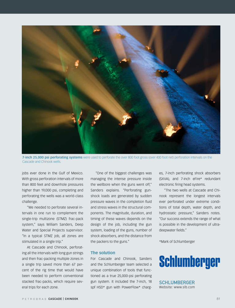
P E T R O B R A S CASCADE | CHINOOK 81
SCHlumBErGErWebsite: www.slb.com
jobs ever done in the Gulf of Mexico.
With gross perforation intervals of more
than 800 feet and downhole pressures
higher than 19,000 psi, completing and
perforating the wells was a world-class
challenge.
“We needed to perforate several in-
tervals in one run to complement the
single-trip multizone (STMZ) frac-pack
system,” says William Sanders, Deep
Water and Special Projects supervisor.
“In a typical STMZ job, all zones are
stimulated in a single trip.”
At Cascade and Chinook, perforat-
ing all the intervals with long gun strings
andthenfrac-packingmultiplezonesin
a single trip saved more than 67 per-
cent of the rig time that would have
been needed to perform conventional
stacked frac-packs, which require sev-
eraltripsforeachzone.
“Oneof thebiggestchallengeswas
managing the intense pressure inside
the wellbore when the guns went off,”
Sanders explains. “Perforating gun-
shock loads are generated by sudden
pressure waves in the completion fluid
and stress waves in the structural com-
ponents. The magnitude, duration, and
timing of these waves depends on the
design of the job, including the gun
system, loading of the guns, number of
shock absorbers, and the distance from
the packers to the guns.”
The solutionFor Cascade and Chinook, Sanders
and the Schlumberger team selected a
unique combination of tools that func-
tioned as a true 25,000-psi perforating
gun system. It included the 7-inch, 18
spf HSD* gun with PowerFlow* charg-
es, 7-inch perforating shock absorbers
(SXVA), and 7-inch eFire* redundant
electronic firing head systems.
“The two wells at Cascade and Chi-
nook represent the longest intervals
ever perforated under extreme condi-
tions of total depth, water depth, and
hydrostatic pressure,” Sanders notes.
“Oursuccessextendstherangeofwhat
is possible in the development of ultra-
deepwater fields.”
*Mark of Schlumberger
7-inch 25,000 psi perforating systems were used to perforate the over 800 foot gross (over 400 foot net) perforation intervals on the Cascade and Chinook wells.
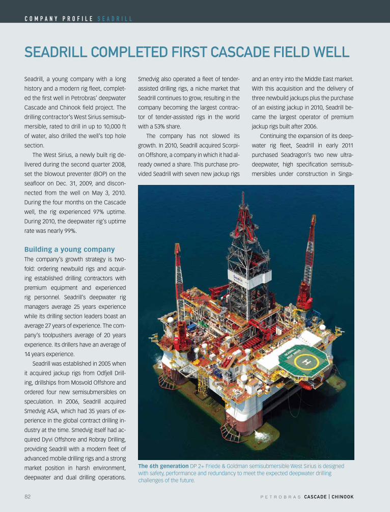
82 P E T R O B R A S CASCADE | CHINOOK
C o m p a n y p r o f i l e S e a D r i l l
SEADrIll COmplETED fIrST CASCADE fIElD WEll
Seadrill, a young company with a long
history and a modern rig fleet, complet-
ed the first well in Petrobras’ deepwater
Cascade and Chinook field project. The
drilling contractor’s West Sirius semisub-
mersible, rated to drill in up to 10,000 ft
of water, also drilled the well’s top hole
section.
The West Sirius, a newly built rig de-
livered during the second quarter 2008,
settheblowoutpreventer (BOP)onthe
seafloor on Dec. 31, 2009, and discon-
nected from the well on May 3, 2010.
DuringthefourmonthsontheCascade
well, the rig experienced 97% uptime.
During2010,thedeepwaterrig’suptime
rate was nearly 99%.
Building a young companyThe company’s growth strategy is two-
fold: ordering newbuild rigs and acquir-
ing established drilling contractors with
premium equipment and experienced
rig personnel. Seadrill’s deepwater rig
managers average 25 years experience
while its drilling section leaders boast an
average 27 years of experience. The com-
pany’s toolpushers average of 20 years
experience. Its drillers have an average of
14 years experience.
Seadrill was established in 2005 when
it acquired jackup rigs fromOdfjell Drill-
ing,drillshipsfromMosvoldOffshoreand
ordered four new semisubmersibles on
speculation. In 2006, Seadrill acquired
Smedvig ASA, which had 35 years of ex-
perience in the global contract drilling in-
dustry at the time. Smedvig itself had ac-
quiredDyviOffshoreandRobrayDrilling,
providing Seadrill with a modern fleet of
advanced mobile drilling rigs and a strong
market position in harsh environment,
deepwater and dual drilling operations.
Smedvig also operated a fleet of tender-
assisted drilling rigs, a niche market that
Seadrill continues to grow, resulting in the
company becoming the largest contrac-
tor of tender-assisted rigs in the world
with a 53% share.
The company has not slowed its
growth. In 2010, Seadrill acquired Scorpi-
onOffshore,acompanyinwhichithadal-
ready owned a share. This purchase pro-
vided Seadrill with seven new jackup rigs
andanentryintotheMiddleEastmarket.
With this acquisition and the delivery of
three newbuild jackups plus the purchase
of an existing jackup in 2010, Seadrill be-
came the largest operator of premium
jackup rigs built after 2006.
Continuing the expansion of its deep-
water rig fleet, Seadrill in early 2011
purchased Seadragon’s two new ultra-
deepwater, high specification semisub-
mersibles under construction in Singa-
The 6th generationDP2+Friede&GoldmansemisubmersibleWestSiriusisdesignedwith safety, performance and redundancy to meet the expected deepwater drilling challenges of the future.
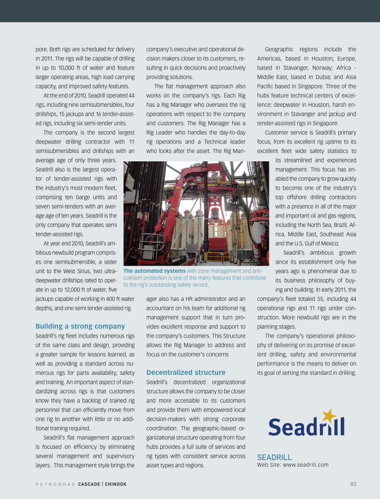
P E T R O B R A S CASCADE | CHINOOK 83
SEADrIllWeb Site: www.seadrill.com
pore. Both rigs are scheduled for delivery
in 2011. The rigs will be capable of drilling
in up to 10,000 ft of water and feature
larger operating areas, high load carrying
capacity, and improved safety features.
At the end of 2010, Seadrill operated 44
rigs, including nine semisubmersibles, four
drillships, 15 jackups and 16 tender-assist-
ed rigs, including six semi-tender units.
The company is the second largest
deepwater drilling contractor with 11
semisubmersibles and drillships with an
average age of only three years.
Seadrill also is the largest opera-
tor of tender-assisted rigs with
the industry’s most modern fleet,
comprising ten barge units and
seven semi-tenders with an aver-
age age of ten years. Seadrill is the
only company that operates semi
tender-assisted rigs.
At year end 2010, Seadrill’s am-
bitious newbuild program compris-
es one semisubmersible, a sister
unit to the West Sirius, two ultra-
deepwater drillships rated to oper-
ate in up to 12,000 ft of water, five
jackups capable of working in 400 ft water
depths, and one semi tender-assisted rig.
Building a strong companySeadrill’s rig fleet includes numerous rigs
of the same class and design, providing
a greater sample for lessons learned, as
well as providing a standard across nu-
merous rigs for parts availability, safety
and training. An important aspect of stan-
dardizing across rigs is that customers
know they have a backlog of trained rig
personnel that can efficiently move from
one rig to another with little or no addi-
tional training required.
Seadrill’s flat management approach
is focused on efficiency by eliminating
several management and supervisory
layers. This management style brings the
company’s executive and operational de-
cision makers closer to its customers, re-
sulting in quick decisions and proactively
providing solutions.
The flat management approach also
works on the company’s rigs. Each Rig
has a Rig Manager who oversees the rig
operations with respect to the company
and customers. The Rig Manager has a
Rig Leader who handles the day-to-day
rig operations and a Technical leader
who looks after the asset. The Rig Man-
ageralsohasaHRadministratorandan
accountant on his team for additional rig
management support that in turn pro-
vides excellent response and support to
the company’s customers. This Structure
allows the Rig Manager to address and
focus on the customer’s concerns
Decentralized structureSeadrill’s decentralized organizational
structure allows the company to be closer
and more accessible to its customers
and provide them with empowered local
decision-makers with strong corporate
coordination. The geographic-based or-
ganizationalstructureoperatingfromfour
hubs provides a full suite of services and
rig types with consistent service across
asset types and regions.
Geographic regions include the
Americas, based in Houston; Europe,
based in Stavanger, Norway; Africa -
Middle East, based in Dubia; and Asia
Pacific based in Singapore. Three of the
hubs feature technical centers of excel-
lence:deepwaterinHouston,harshen-
vironment in Stavanger and jackup and
tender-assisted rigs in Singapore.
Customer service is Seadrill’s primary
focus, from its excellent rig uptime to its
excellent fleet wide safety statistics to
its streamlined and experienced
management. This focus has en-
abled the company to grow quickly
to become one of the industry’s
top offshore drilling contractors
with a presence in all of the major
and important oil and gas regions,
includingtheNorthSea,Brazil,Af-
rica, Middle East, Southeast Asia
and the U.S. Gulf of Mexico.
Seadrill’s ambitious growth
since its establishment only five
years ago is phenomenal due to
its business philosophy of buy-
ing and building. In early 2011, the
company’s fleet totaled 55, including 44
operational rigs and 11 rigs under con-
struction. More newbuild rigs are in the
planning stages.
The company’s operational philoso-
phy of delivering on its promise of excel-
lent drilling, safety and environmental
performance is the means to deliver on
its goal of setting the standard in drilling.
The automated systemswithzonemanagementandanti-collision protection is one of the many features that contribute to the rig’s outstanding safety record.
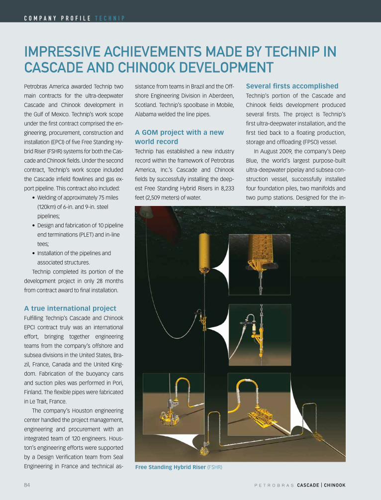
84 P E T R O B R A S CASCADE | CHINOOK
C o m p a n y p r o f i l e T e C h n i p
ImprESSIVE ACHIEVEmENTS mADE By TECHNIp IN CASCADE AND CHINOOK DEVElOpmENTPetrobras America awarded Technip two
main contracts for the ultra-deepwater
Cascade and Chinook development in
the Gulf of Mexico. Technip’s work scope
under the first contract comprised the en-
gineering, procurement, construction and
installation(EPCI)offiveFreeStandingHy-
bridRiser(FSHR)systemsforboththeCas-
cade and Chinook fields. Under the second
contract, Technip’s work scope included
the Cascade infield flowlines and gas ex-
port pipeline. This contract also included:
• Weldingofapproximately75miles
(120km) of 6-in. and 9-in. steel
pipelines;
• Designandfabricationof10pipeline
endterminations(PLET)andin-line
tees;
• Installationofthepipelinesand
associated structures.
Technip completed its portion of the
development project in only 28 months
from contract award to final installation.
A true international projectFulfilling Technip’s Cascade and Chinook
EPCI contract truly was an international
effort, bringing together engineering
teams from the company’s offshore and
subsea divisions in the United States, Bra-
zil, France,Canadaand theUnitedKing-
dom. Fabrication of the buoyancy cans
and suction piles was performed in Pori,
Finland. The flexible pipes were fabricated
in Le Trait, France.
The company’s Houston engineering
center handled the project management,
engineering and procurement with an
integratedteamof120engineers.Hous-
ton’s engineering efforts were supported
byaDesignVerification team fromSeal
Engineering in France and technical as-
sistancefromteamsinBrazilandtheOff-
shoreEngineeringDivision inAberdeen,
Scotland. Technip’s spoolbase in Mobile,
Alabama welded the line pipes.
A GOM project with a new world recordTechnip has established a new industry
record within the framework of Petrobras
America, Inc.’s Cascade and Chinook
fields by successfully installing the deep-
est Free StandingHybrid Risers in 8,233
feet (2,509 meters) of water.
Several firsts accomplishedTechnip’s portion of the Cascade and
Chinook fields development produced
several firsts. The project is Technip’s
first ultra-deepwater installation, and the
first tied back to a floating production,
storageandoffloading(FPSO)vessel.
InAugust2009,thecompany’sDeep
Blue, the world’s largest purpose-built
ultra-deepwater pipelay and subsea con-
struction vessel, successfully installed
four foundation piles, two manifolds and
twopumpstations.Designedforthein-
Free Standing Hybrid Riser(FSHR)
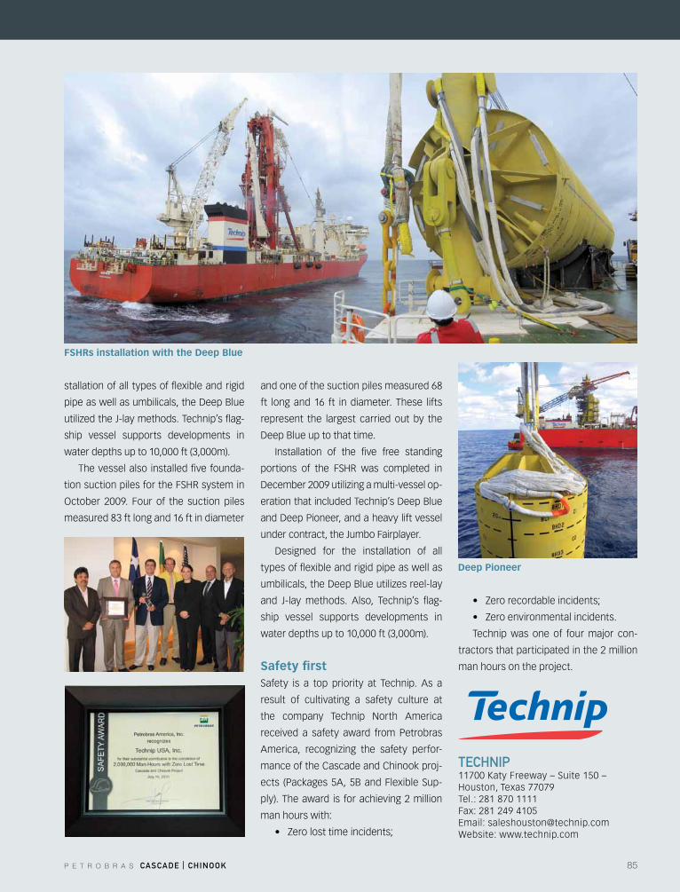
P E T R O B R A S CASCADE | CHINOOK 85
stallation of all types of flexible and rigid
pipeaswellasumbilicals,theDeepBlue
utilizedtheJ-laymethods.Technip’sflag-
ship vessel supports developments in
water depths up to 10,000 ft (3,000m).
The vessel also installed five founda-
tionsuctionpilesfortheFSHRsystemin
October 2009. Four of the suction piles
measured 83 ft long and 16 ft in diameter
and one of the suction piles measured 68
ft long and 16 ft in diameter. These lifts
represent the largest carried out by the
DeepBlueuptothattime.
Installation of the five free standing
portions of the FSHR was completed in
December2009utilizingamulti-vesselop-
erationthatincludedTechnip’sDeepBlue
andDeepPioneer,andaheavyliftvessel
under contract, the Jumbo Fairplayer.
Designed for the installation of all
types of flexible and rigid pipe as well as
umbilicals,theDeepBlueutilizesreel-lay
and J-lay methods. Also, Technip’s flag-
ship vessel supports developments in
water depths up to 10,000 ft (3,000m).
Safety firstSafety is a top priority at Technip. As a
result of cultivating a safety culture at
the company Technip North America
received a safety award from Petrobras
America, recognizing the safety perfor-
mance of the Cascade and Chinook proj-
ects (Packages 5A, 5B and Flexible Sup-
ply). The award is for achieving 2 million
man hours with:
• Zerolosttimeincidents;
• Zerorecordableincidents;
• Zeroenvironmentalincidents.
Technip was one of four major con-
tractors that participated in the 2 million
man hours on the project.
TECHNIp11700 Katy Freeway – Suite 150 – Houston,Texas77079Tel.: 281 870 1111Fax: 281 249 4105Email:[email protected]: www.technip.com
FSHRs installation with the Deep Blue
Deep Pioneer
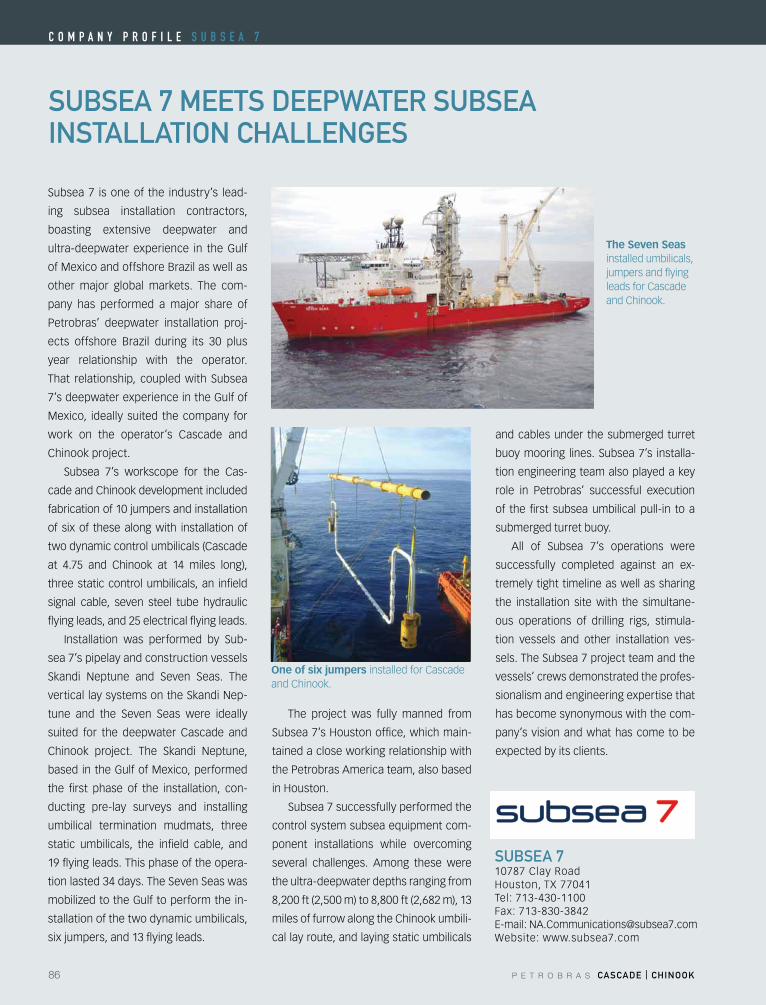
86 P E T R O B R A S CASCADE | CHINOOK
C o m p a n y p r o f i l e S u B S e a 7
One of six jumpers installed for Cascade and Chinook.
SuBSEA 7 mEETS DEEpWATEr SuBSEA INSTAllATION CHAllENGES
Subsea 7 is one of the industry’s lead-
ing subsea installation contractors,
boasting extensive deepwater and
ultra-deepwater experience in the Gulf
ofMexicoandoffshoreBrazilaswellas
other major global markets. The com-
pany has performed a major share of
Petrobras’ deepwater installation proj-
ects offshore Brazil during its 30 plus
year relationship with the operator.
That relationship, coupled with Subsea
7’s deepwater experience in the Gulf of
Mexico, ideally suited the company for
work on the operator’s Cascade and
Chinook project.
Subsea 7’s workscope for the Cas-
cade and Chinook development included
fabrication of 10 jumpers and installation
of six of these along with installation of
two dynamic control umbilicals (Cascade
at 4.75 and Chinook at 14 miles long),
three static control umbilicals, an infield
signal cable, seven steel tube hydraulic
flying leads, and 25 electrical flying leads.
Installation was performed by Sub-
sea 7’s pipelay and construction vessels
Skandi Neptune and Seven Seas. The
vertical lay systems on the Skandi Nep-
tune and the Seven Seas were ideally
suited for the deepwater Cascade and
Chinook project. The Skandi Neptune,
based in the Gulf of Mexico, performed
the first phase of the installation, con-
ducting pre-lay surveys and installing
umbilical termination mudmats, three
static umbilicals, the infield cable, and
19 flying leads. This phase of the opera-
tion lasted 34 days. The Seven Seas was
mobilizedtotheGulftoperformthein-
stallation of the two dynamic umbilicals,
six jumpers, and 13 flying leads.
The project was fully manned from
Subsea7’sHoustonoffice,whichmain-
tained a close working relationship with
the Petrobras America team, also based
inHouston.
Subsea 7 successfully performed the
control system subsea equipment com-
ponent installations while overcoming
several challenges. Among these were
the ultra-deepwater depths ranging from
8,200 ft (2,500 m) to 8,800 ft (2,682 m), 13
miles of furrow along the Chinook umbili-
cal lay route, and laying static umbilicals
and cables under the submerged turret
buoy mooring lines. Subsea 7’s installa-
tion engineering team also played a key
role in Petrobras’ successful execution
of the first subsea umbilical pull-in to a
submerged turret buoy.
All of Subsea 7’s operations were
successfully completed against an ex-
tremely tight timeline as well as sharing
the installation site with the simultane-
ous operations of drilling rigs, stimula-
tion vessels and other installation ves-
sels. The Subsea 7 project team and the
vessels’ crews demonstrated the profes-
sionalism and engineering expertise that
has become synonymous with the com-
pany’s vision and what has come to be
expected by its clients.
SuBSEA 710787 Clay RoadHouston,TX77041Tel: 713-430-1100Fax: 713-830-3842E-mail:[email protected]: www.subsea7.com
The Seven Seas installed umbilicals, jumpers and flying leads for Cascade and Chinook.
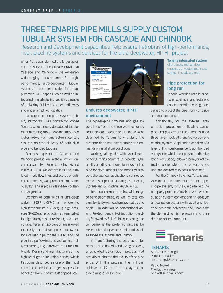
P E T R O B R A S CASCADE | CHINOOK 87
THrEE TENArIS pIpE mIllS Supply CuSTOmTuBulAr SySTEm fOr CASCADE AND CHINOOK
TENArISMariano ArmengolProduct [email protected]
Paolo NovelliProduct [email protected]
When Petrobras planned the largest proj-
ect it has ever done outside Brazil – at
Cascade and Chinook – the extremely
wide-ranging requirements for high-
performance, ultra-deepwater tubular
systems for both fields called for a sup-
plierwithR&Dcapabilitiesaswellas in-
tegrated manufacturing facilities capable
of delivering finished products efficiently
and under simplified logistics.
To supply this complete system Tech-
nip, Petrobras’ EPCI contractor, chose
Tenaris, whose many decades of tubular
manufacturing know-how and integrated
global network of manufacturing centers
assured on-time delivery of both rigid
pipe and bended tubulars.
Seamless pipe for the Cascade and
Chinook production system, which en-
compasses five Free Standing Hybrid
Risers(FSHRs),gasexportlinesandinsu-
lated infield flow lines and scores of criti-
cal pipe bends, was provided simultane-
ously by Tenaris pipe mills in Mexico, Italy
and Argentina.
Location of both fields in ultra-deep
water – 8,887 ft (2,740 m) – where the
high-temperature (250 deg. F), high-pres-
sure (19,000 psi) production stream called
for high-strength sour resistant, and coat-
edpipe,Tenaris’R&Dcapabilitiesallowed
the design and development of 18,000
tonsof rigidpipe for theFSHRsand the
pipe-in-pipe flowlines, as well as internal-
ly tensioned, high-strength rods for um-
bilicals.Designandmanufacturingofthe
high steel-grade induction bends, which
Petrobras described as one of the most
critical products in the project scope, also
benefitedfromTenaris’R&Dcapabilities.
Endures deepwater, HP-HT environmentThe pipe-in-pipe flowlines and gas ex-
port lines from the three wells currently
producing at Cascade and Chinook were
designed by Tenaris to withstand the
extreme deep-sea environment and de-
manding installation conditions.
Working alongside with world-class
bending manufacturers to provide high-
quality bending solutions, Tenaris supplied
pipe for both jumpers and bends to sup-
port the seafloor applications connected
to the development’s Floating Production,
StorageandOffloading(FPSO)facility.
Tenaris customers obtain a wide range
of bend geometries, as well as total de-
signflexibilitywithcustomizedradiusand
angle – in addition to conventional 45-
and90-deg.bends.Hot inductionbend-
ing followed by full off-line quenching and
tempering is the preferred process for
HP-HT,ultra-deepwatersteelbendssuch
as those at Cascade and Chinook.
In manufacturing the pipe used, Te-
narisapplieditscoldendsizingprocess,
a controlled deformation process that
actuallyminimizestheovalityofthepipe
ends. With this process, the mill can
achieve +/- 1.2 mm from the agreed in-
side diameter of the pipe.
Pipe protection for long runTenaris, working with interna-
tional coating manufacturers,
chose specific coatings de-
signed to protect the pipe from corrosive
and erosion effects.
Additionally, for the external anti-
corrosion protection of flowline carrier
pipe and gas export lines, Tenaris used
three-layer polyethylene/polypropylene
coating system. Application consists of a
layer of high-performance fusion bonded
epoxy onto which a co-polymer adhesive
layer is extruded, followed by layers of ex-
truded polyethylene and polypropylene
until the desired thickness is obtained.
For the Chinook flowlines Tenaris pro-
vide inner and outer pipe, for the pipe-
in-pipe system, for the Cascade field the
company provides flowlines with wet in-
sulation system conventional three-layer
anticorrosion system with additional lay-
er of syntactic polypropylene, usable for
the demanding high pressure and ultra
deep water environment.
ResearchandDevelopmentcapabilitieshelpassurePetrobrasofhigh-performance,riser,pipelinesystemsandservicesfortheultra-deepwater,HP-HTproject
Tenaris integrated system of products and services ensures our customers’ most stringent needs are met.
C o m p a n y p r o f i l e T e n a r i S
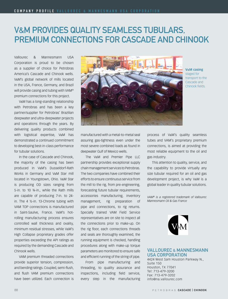
88 P E T R O B R A S CASCADE | CHINOOK
V&m prOVIDES QuAlITy SEAmlESS TuBulArS, prEmIum CONNECTIONS fOr CASCADE AND CHINOOK
VAllOurEC & mANNESmANN uSA COrpOrATION4424WestSamHoustonParkwayN.,Suite 150Houston,TX77041Tel: 713-479-3200Fax: [email protected]
Vallourec & Mannesmann USA
Corporation is proud to be chosen
as a supplier of choice for Petrobras
America’s Cascade and Chinook wells.
V&M’s global network of mills located
intheUSA,France,Germany,andBrazil
will provide casing and tubing with VAM®
premium connections for this project.
V&M has a long-standing relationship
with Petrobras and has been a key
partner/supplier forPetrobras’Brazilian
deepwater and ultra-deepwater projects
and operations through the years. By
delivering quality products combined
with logistical expertise, V&M has
demonstrated a continued commitment
to developing best-in-class performance
for tubular solutions.
In the case of Cascade and Chinook,
the majority of the casing has been
produced in V&M’s Dusseldorf-Rath
Works in Germany and V&M Star mill
located in Youngstown,Ohio. V&M Star
is producing OD sizes ranging from
5-in. to 10 ¾-in., while the Rath mills
are capable of producing 7-in. to 24-
in. The 4 ½-in. 13-Chrome tubing with
VAMTOPconnections ismanufactured
in Saint-Saulve, France. V&M’s hot-
rolling manufacturing process ensures
controlled wall thickness and ovality,
minimum residual stresses, while V&M’s
High Collapse proprietary grades offer
properties exceeding the API ratings as
required by the demanding Cascade and
Chinook wells.
VAM premium threaded connections
provide superior tension, compression,
and bending ratings. Coupled, semi-flush,
and flush VAM premium connections
have been utilized. Each connection is
manufactured with a metal-to-metal seal
assuring gas-tightness even under the
most severe combined loads as found in
deepwater Gulf of Mexico wells.
The V&M and Premier Pipe LLC
partnership provides exceptional supply
chain management services to Petrobras.
The two companies have combined their
efforts to ensure continuous service from
the mill to the rig, from pre-engineering,
forecasting future tubular requirements,
accessories manufacturing, inventory
management, rig preparation of
pipe and connections, to rig returns.
Specially trained VAM Field Service
representatives are on site to inspect all
the connections prior to make-up. On
the rig floor, each connections threads
and seals are thoroughly examined, the
running equipment is checked, handling
procedures along with make-up torque
parameters are monitored to ensure safe
and efficient running of the string of pipe.
From pipe manufacturing and
threading, to quality assurance and
inspections, including field service,
every step in the manufacturing
process of V&M’s quality seamless
tubes and VAM’s proprietary premium
connections, is aimed at providing the
most reliable equipment to the oil and
gas industry.
This attention to quality, service, and
the capability to provide virtually any
size tubular required foranoilandgas
development project, is why V&M is a
global leader in quality tubular solutions.
VAM® is a registered trademark of Vallourec Mannesmann Oil & Gas France
V&M casing staged for transport to the Cascade and Chinook fields.
C o m p a n y p r o f i l e V a l l o u r e C & m a n n e S m a n n u S a C o r p o r a T i o n
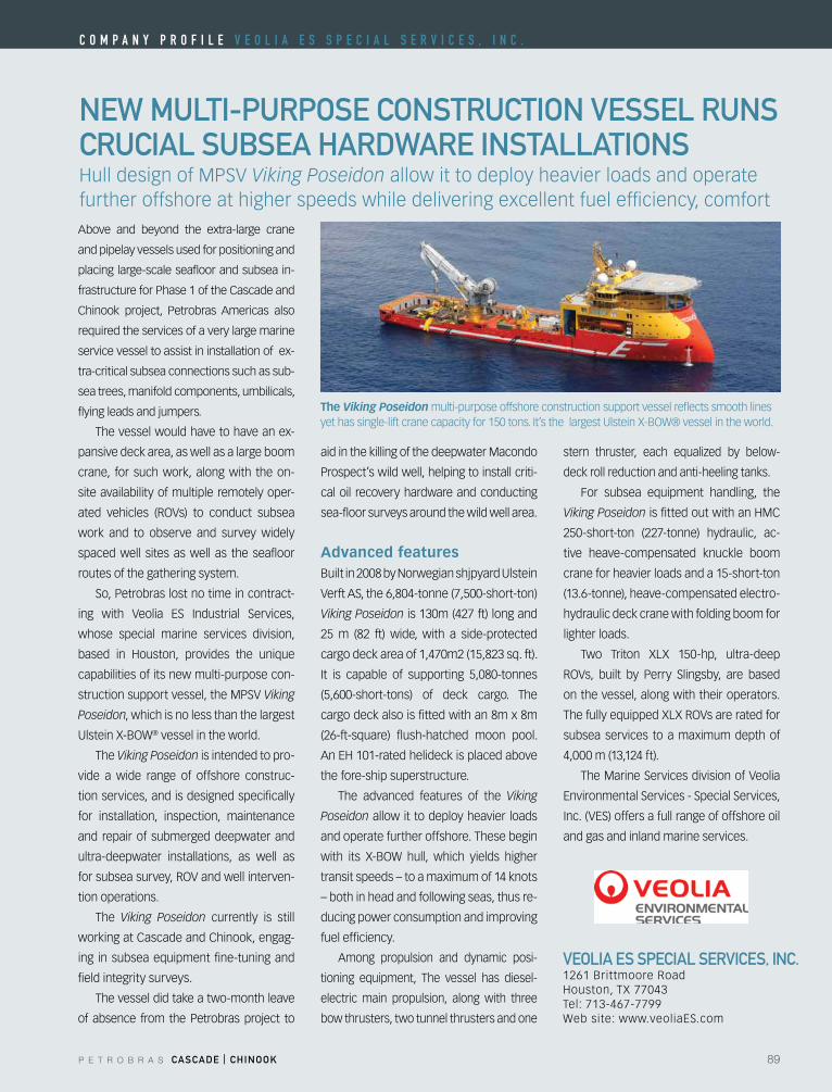
P E T R O B R A S CASCADE | CHINOOK 89
NEW mulTI-purpOSE CONSTruCTION VESSEl ruNS CruCIAl SuBSEA HArDWArE INSTAllATIONS
VEOlIA ES SpECIAl SErVICES, INC.1261 Brittmoore RoadHouston,TX77043Tel: 713-467-7799Website:www.veoliaES.com
Above and beyond the extra-large crane
and pipelay vessels used for positioning and
placing large-scale seafloor and subsea in-
frastructure for Phase 1 of the Cascade and
Chinook project, Petrobras Americas also
required the services of a very large marine
service vessel to assist in installation of ex-
tra-critical subsea connections such as sub-
sea trees, manifold components, umbilicals,
flying leads and jumpers.
The vessel would have to have an ex-
pansive deck area, as well as a large boom
crane, for such work, along with the on-
site availability of multiple remotely oper-
ated vehicles (ROVs) to conduct subsea
work and to observe and survey widely
spaced well sites as well as the seafloor
routes of the gathering system.
So, Petrobras lost no time in contract-
ing with Veolia ES Industrial Services,
whose special marine services division,
based in Houston, provides the unique
capabilities of its new multi-purpose con-
struction support vessel, the MPSV Viking
Poseidon, which is no less than the largest
UlsteinX-BOW® vessel in the world.
The Viking Poseidon is intended to pro-
vide a wide range of offshore construc-
tion services, and is designed specifically
for installation, inspection, maintenance
and repair of submerged deepwater and
ultra-deepwater installations, as well as
forsubseasurvey,ROVandwellinterven-
tion operations.
The Viking Poseidon currently is still
working at Cascade and Chinook, engag-
ing in subsea equipment fine-tuning and
field integrity surveys.
The vessel did take a two-month leave
of absence from the Petrobras project to
aid in the killing of the deepwater Macondo
Prospect’s wild well, helping to install criti-
cal oil recovery hardware and conducting
sea-floor surveys around the wild well area.
Advanced featuresBuilt in 2008 by Norwegian shjpyard Ulstein
Verft AS, the 6,804-tonne (7,500-short-ton)
Viking Poseidon is 130m (427 ft) long and
25 m (82 ft) wide, with a side-protected
cargo deck area of 1,470m2 (15,823 sq. ft).
It is capable of supporting 5,080-tonnes
(5,600-short-tons) of deck cargo. The
cargo deck also is fitted with an 8m x 8m
(26-ft-square) flush-hatched moon pool.
AnEH101-ratedhelideckisplacedabove
the fore-ship superstructure.
The advanced features of the Viking
Poseidon allow it to deploy heavier loads
and operate further offshore. These begin
with its X-BOW hull, which yields higher
transit speeds – to a maximum of 14 knots
– both in head and following seas, thus re-
ducing power consumption and improving
fuel efficiency.
Among propulsion and dynamic posi-
tioning equipment, The vessel has diesel-
electric main propulsion, along with three
bow thrusters, two tunnel thrusters and one
stern thruster, each equalized by below-
deck roll reduction and anti-heeling tanks.
For subsea equipment handling, the
Viking PoseidonisfittedoutwithanHMC
250-short-ton (227-tonne) hydraulic, ac-
tive heave-compensated knuckle boom
crane for heavier loads and a 15-short-ton
(13.6-tonne), heave-compensated electro-
hydraulic deck crane with folding boom for
lighter loads.
Two Triton XLX 150-hp, ultra-deep
ROVs, built by Perry Slingsby, are based
on the vessel, along with their operators.
ThefullyequippedXLXROVsareratedfor
subsea services to a maximum depth of
4,000 m (13,124 ft).
The Marine Services division of Veolia
EnvironmentalServices-SpecialServices,
Inc.(VES)offersafullrangeofoffshoreoil
and gas and inland marine services.
HulldesignofMPSVViking Poseidon allow it to deploy heavier loads and operate further offshore at higher speeds while delivering excellent fuel efficiency, comfort
The Viking Poseidon multi-purpose offshore construction support vessel reflects smooth lines yethassingle-liftcranecapacityfor150tons.It’sthelargestUlsteinX-BOW®vesselintheworld.
C o m p a n y p r o f i l e V e o l i a e S S p e C i a l S e r V i C e S , i n C .

PE
TR
OB
RA
S
ca
sc
aD
E a
ND
ch
INO
Ok