Peter Chochula ALICE DCS Workshop, October 6,2005 PVSSII Alert Handling.
25
Peter Chochula ALICE DCS Workshop, October 6,2005 PVSSII Alert Handling
-
Upload
estella-wood -
Category
Documents
-
view
217 -
download
3
Transcript of Peter Chochula ALICE DCS Workshop, October 6,2005 PVSSII Alert Handling.
Peter ChochulaALICE DCS Workshop, October 6,2005
PVSSII Alert Handling
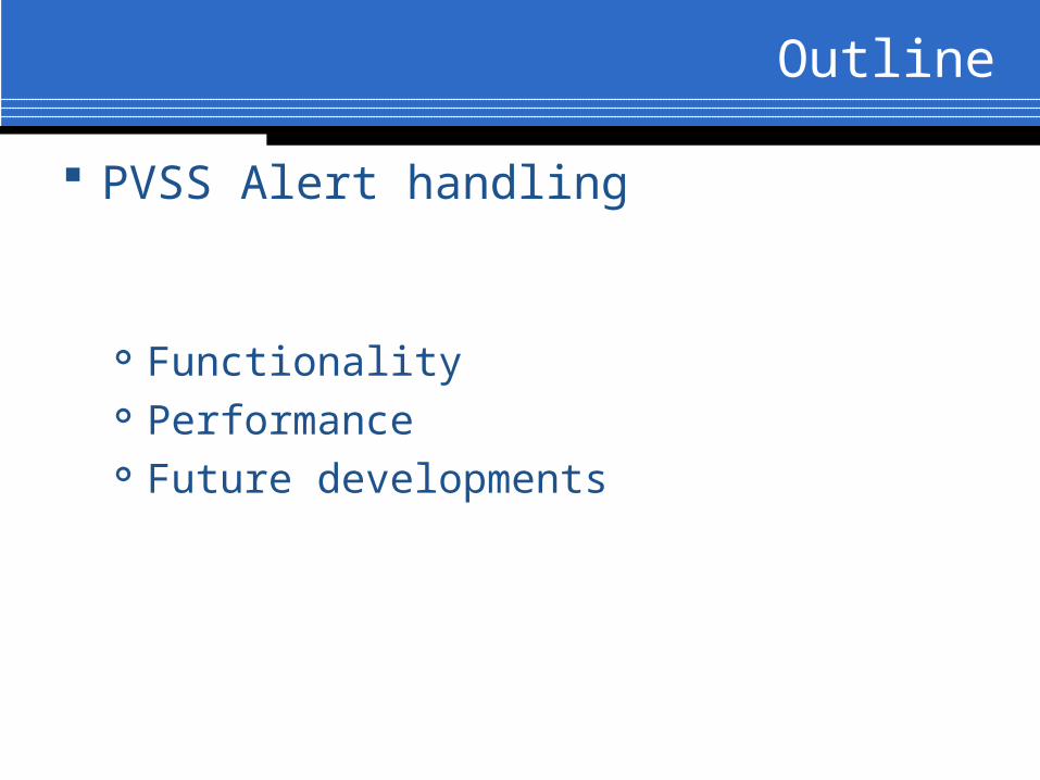
Outline
PVSS Alert handling
Functionality Performance Future developments

PVSSII offers a comprehensive alert handling strategy based on industrial standards: DIN 3699 Process control using display
screens DIN 19235 Measurement and control;
signaling of operating conditions

Alerts are sent if the monitored DPE value changes from one alert range to another
Alerts can be visualized : As text on alert screen As state display (e.g. flashing graphical element)
Alerts might require acknowledgment on the AES
Automatic functions can be assigned to alerts The function is executed when the alert is triggered
Priorities and Priority Levels in the PVSS
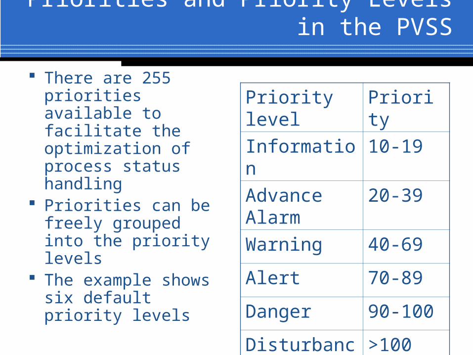
There are 255 priorities available to facilitate the optimization of process status handling
Priorities can be freely grouped into the priority levels
The example shows six default priority levels
Priority level Priority
Information 10-19
Advance Alarm
20-39
Warning 40-69
Alert 70-89
Danger 90-100
Disturbance >100

Alert Ranges
Alert ranges must be assigned to priority levels
For each DPE at least two ranges must exist:
Valid range (Priority 0) Alert range
Example: temperature probe with 5 defined ranges
Alert Range Numerical range
Priority level
Very high value above limit
> 50 C Danger
High value above limit
30-50 C Alert
Valid 20-30 C 0
Low value below limit
10-20 C Alert
Very low value below limit
<10 C Danger
Alert Classes
Alert classes simplify the parameterization of alert handling
by grouping together the parameterizable properties of alert ranges of datapoint elements
Each alert has an alert class assigned Alert class describes the acknowledgment mode for the alert CTRL script can be used for example to change the status of
graphical elements, start the horn, display a message etc. The six default alert levels shown in the previous slide
correspond to six default alert classes (information, advance alarm, warning, alert, danger, disturbance)
Users can define additional alert classes

Example of Alert Parametrization Using Ranges and Classes

Alert Statuses
Each alert can have one of 5 possible statuses: No Alert – normal status Incoming not acknowledged – alert active,
not yet acknowledged Incoming acknowledged – alert active,
already acknowledged Outgoing unacknowledged – status not
pending, not yet acknowledged Outgoing acknowledged – status not
pending, already acknowledged

Acknowledgment types
Acknowledgment types are assigned to DPEs to allow for different handling algorithms
1. Not acknowledgeable – alert changes only as a result of status change
2. Acknowledgment deletes – pending alert is reset to No Alert
3. Incoming acknowledgeable – the message is acknowledgeable
4. Alert pair requires acknowledgement – same as 3, but outgoing alert also requires acknowledgment. New alert overwrites the old one
5. Incoming and Outgoing require acknowledgement – same as 4, but both alerts must be acknowledged (new alert does not overwrite the old one)

Group alerts
Several alerts can be OR linked to form a group alert An alert is fired if any of the linked alerts is
pending
Using the panel topology the group alerts can be linked across several panels Only summary information Is brought to the
attention of the operator (e.g. crate has a problem if any of the channels has a problem)

Suppression of alerts
Suppression function can activate/deactivate any of the alerts Very useful feature if the monitored value is
outside of limits, but this is irrelevant for the process (e.g. current fluctuations during ramping process or FERO configuration)
Suppressed alerts are considered as non-existent

Alert Hysteresis
Hysteresis is defined to avoid repeated alert generation for values fluctuating around the alert limit
Value related hysteresis uses dead zones around the alert limit
Time hysteresis for digital values – bit must remain in a given state for certain amount of time
Time hysteresis for analog values – adds time inertia to value related hysteresis

Value related HysteresisR
an
ge
1R
an
ge
2R
an
ge
3
1 2 3 2 1
Upper Limit 1
Lower Limit 2
Upper Limit 2
Lower Limit 3
Upper Limit 3
•Priority levels defined in the PVSS
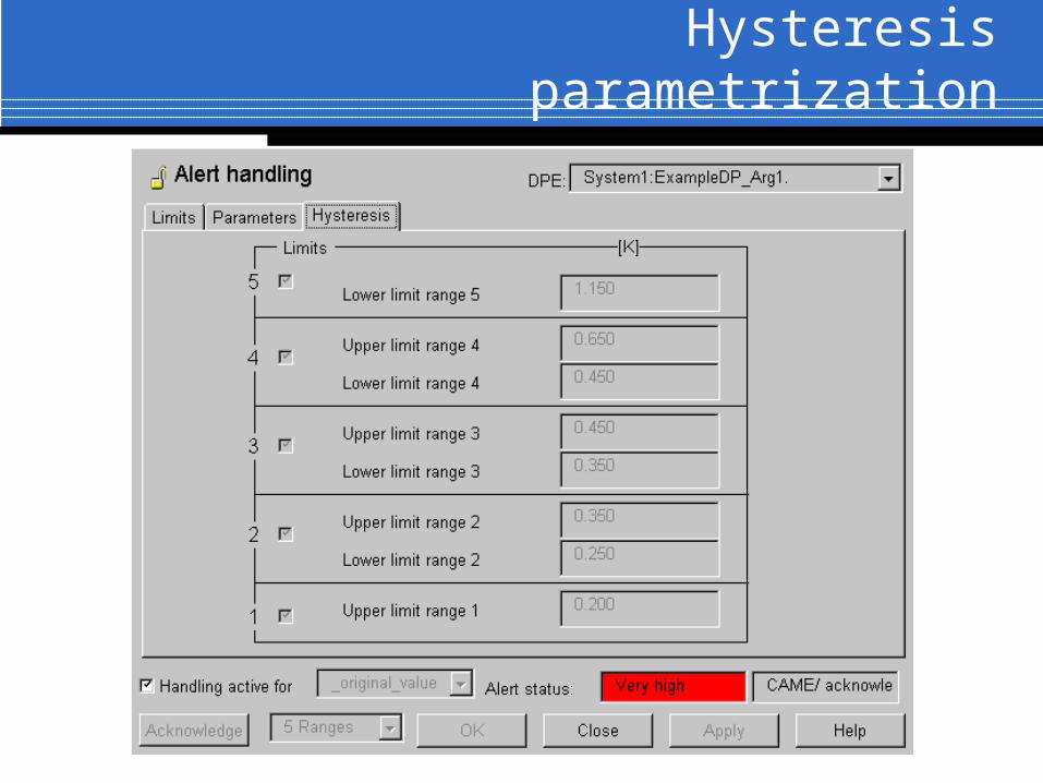
Hysteresis parametrization

Relation between the PVSSII Alert Handling and the FSM
Described alert handling is related to the low-level PVSSII operation
At the detector level, the alerts influence the global states of the detector
Filtering and masking mechanism can affect the reaction of the FSM to the alert status
If a pending alert changes the FSM state, this can be recovered only if the alert status changes or if the alert is masked

Example of the Relation between the PVSSI Alerts and the FSM
Imagine a situation when an overcurrent on a single channel puts the detector into Error condition
Scenario 1: the recovery procedure resets the channel (cures the overcurrent status) and FSM state can be recovered to READY
Scenario 2: the recovery procedure changes the alert range, so the overcurrent will not trigger an alert anymore (but the overcurrent condition will persist)
Scenario 3: the channel will be taken out from the FSM hierarchy, so it will not contribute to the resulting state computation (the error condition on the channel will persist)
Error handling
By default the PVSSII errors are passed to the Log Viewer
Error handler can be used to redirect the errors To the standard output To the database

Alert handling performance
Several tests performed within the SUP and FWWG
SUP (Paul Burkimsher) studied the load of the systems and alert digestion
FWWG (Oliver Holme) studied the efficiency of different alert filtering modes
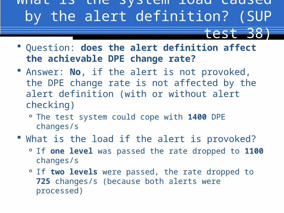
What is the system load caused by the alert definition? (SUP test 38)
Question: does the alert definition affect the achievable DPE change rate?
Answer: No, if the alert is not provoked, the DPE change rate is not affected by the alert definition (with or without alert checking)
The test system could cope with 1400 DPE changes/s
What is the load if the alert is provoked? If one level was passed the rate dropped to 1100
changes/s If two levels were passed, the rate dropped to 725
changes/s (because both alerts were processed)

Memory consumption caused by alert definition (Test 39)
Tests were performed by defining the DPE and comparing the memory used by the EM
After adding alert definition, the memory consumption was recalculated
Declaration of alerts takes extra memory 5 level alert definition requires app. additional
2500 bytes per DPE Activation of alerts take ~2% more memory

Absorption of alerts
Test Setup 2 systems 5 crates defined per
system 256 channels per crate 40000 DPE per system 2 alerts defined per
channel 5 alert ranges per voltage
channel 3 alert ranges per current
channel Each channel was
provoked to pass 2 levels
Test Results 10000 lines (from both
systems) displayed in 30s 1000 came alerts absorbed
in 15s 5000 came alerts cancelled
in 45s Acknowledgments of
10000 alerts takes 2 min 20s
Systems can cope with sustained rate of 200 alerts/s
Interpretation of test results
The described tests showed limits for alert absorbtion by the PVSSII system
Further tests were performed to show the difference between displaying alerts from the local and a remote system
For a typical CAEN crate, all local alerts are displayed within 2 sec
If display of additional alerts from remote system is required, the total time is ~3 sec
Present status abd developments
The alert definition and handling Is fully supported by all FW devices Tools are available in the FW Alert configuration is supported by the FW
configuration database tool
FWWG is studying improved AES screen ETM is working on improved alert filtering
methods

Conclusions
PVSSII offers powerful alert handling mechanism based on industrial standards
A single system can cope with alert avalanche of 10000 alerts
A single system can support a sustained alert rate of ~200 alerts/sec
Group alerts and panel topology allow for efficient alert reporting
In distributed system each AES screen can retrieve alerts from a remote system without significant overhead
New developments are underway