Perspective Drawing Using Adobe® Illustrator® CS5...Adobe Illustrator CS5 n 6 n Perspective...
19
Perspective Drawing Using Adobe® Illustrator® CS5 May 2010
Transcript of Perspective Drawing Using Adobe® Illustrator® CS5...Adobe Illustrator CS5 n 6 n Perspective...
Perspective Drawing Using Adobe® Illustrator® CS5
M ay 2 0 1 0

This document is the property of Adobe® Systems Inc. It is designed and published for education and training of the Adobe® Illustrator® CS5 and is not intended for any other commercial purpose. This is designed by Adobe’s Engineering depart-ment. No claim is made for precision or accuracy of content presented here.
No part of the document may be modified, copied, altered or deleted or presented in any form other than this. No part of this publication may be reproduced in any form or by any means, electronic or mechanical, including photocopying, record-ing, or any information storage and retrieval system, without permission in writing from the publisher and copyright owner.
Copyright © 2010 by ANIL AHUJA for Adobe Systems Inc.
All reference photographs are by the author
Perspective Drawing Using Adobe® Illustrator® CS5
A d o b e I l l u s t r at o r C S 5 n 3 n P e r s p e c t i v e D r aw i n g
ILLUstrAtor Cs5DrAwIng the tAj In PerSPeCtIve
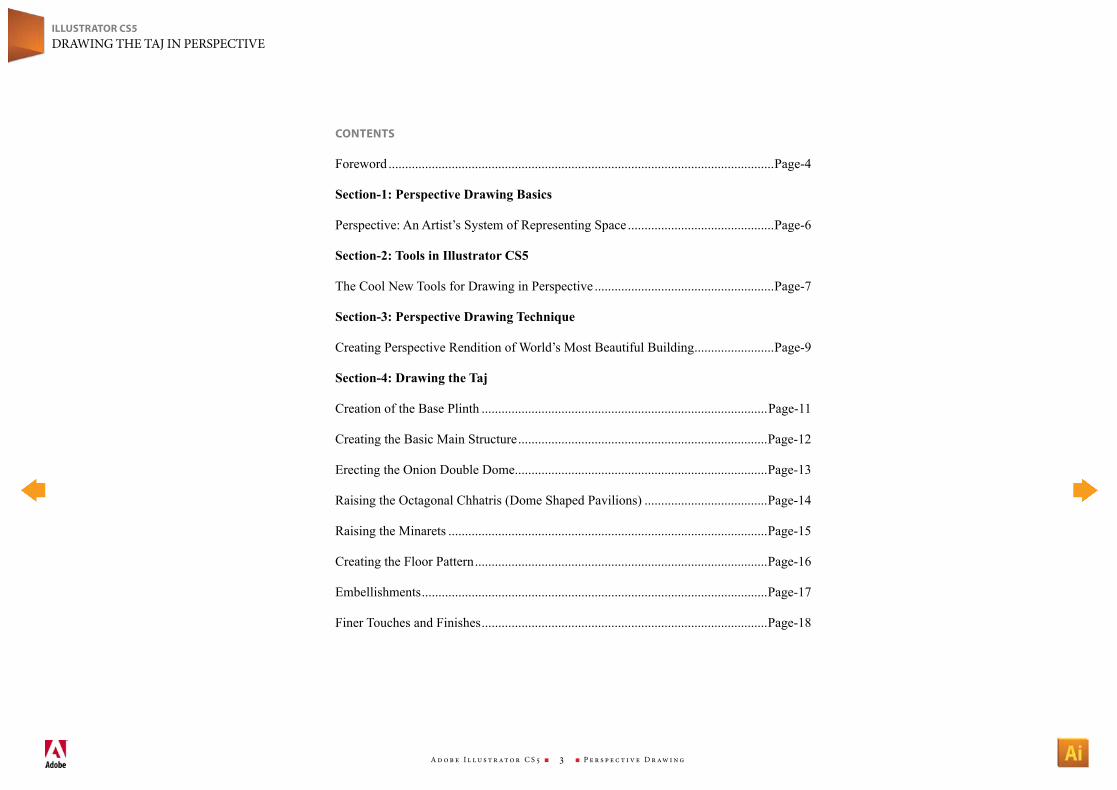
CoNteNts
Foreword ....................................................................................................................Page-4
Section-1: Perspective Drawing Basics
Perspective: An Artist’s System of Representing Space ............................................Page-6
Section-2: Tools in Illustrator CS5
The Cool New Tools for Drawing in Perspective ......................................................Page-7
Section-3: Perspective Drawing Technique
Creating Perspective Rendition of World’s Most Beautiful Building ........................Page-9
Section-4: Drawing the Taj
Creation of the Base Plinth ......................................................................................Page-11
Creating the Basic Main Structure ...........................................................................Page-12
Erecting the Onion Double Dome ............................................................................Page-13
Raising the Octagonal Chhatris (Dome Shaped Pavilions) .....................................Page-14
Raising the Minarets ................................................................................................Page-15
Creating the Floor Pattern ........................................................................................Page-16
Embellishments ........................................................................................................Page-17
Finer Touches and Finishes ......................................................................................Page-18
A d o b e I l l u s t r at o r C S 5 n 4 n P e r s p e c t i v e D r aw i n g
ILLUstrAtor Cs5DrAwIng the tAj In PerSPeCtIve
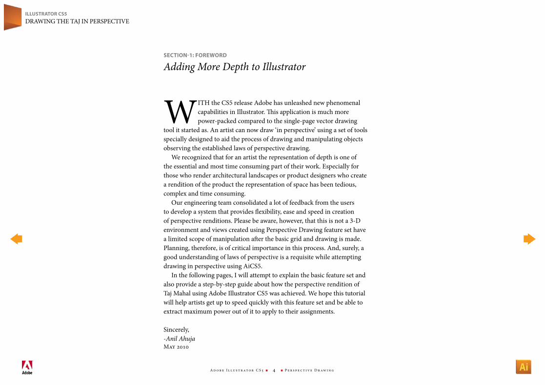
wIth the CS5 release Adobe has unleashed new phenomenal capabilities in Illustrator. This application is much more power-packed compared to the single-page vector drawing
tool it started as. An artist can now draw ‘in perspective’ using a set of tools specially designed to aid the process of drawing and manipulating objects observing the established laws of perspective drawing.
we recognized that for an artist the representation of depth is one of the essential and most time consuming part of their work. especially for those who render architectural landscapes or product designers who create a rendition of the product the representation of space has been tedious, complex and time consuming.
Our engineering team consolidated a lot of feedback from the users to develop a system that provides flexibility, ease and speed in creation of perspective renditions. Please be aware, however, that this is not a 3-D environment and views created using Perspective Drawing feature set have a limited scope of manipulation after the basic grid and drawing is made. Planning, therefore, is of critical importance in this process. And, surely, a good understanding of laws of perspective is a requisite while attempting drawing in perspective using AiCS5.
In the following pages, I will attempt to explain the basic feature set and also provide a step-by-step guide about how the perspective rendition of taj Mahal using Adobe Illustrator CS5 was achieved. we hope this tutorial will help artists get up to speed quickly with this feature set and be able to extract maximum power out of it to apply to their assignments.
Sincerely,-Anil AhujaMay 2010
seCtIoN-1: Foreword
Adding More Depth to Illustrator
A d o b e I l l u s t r at o r C S 5 n 5 n P e r s p e c t i v e D r aw i n g
ILLUstrAtor Cs5DrAwIng the tAj In PerSPeCtIve
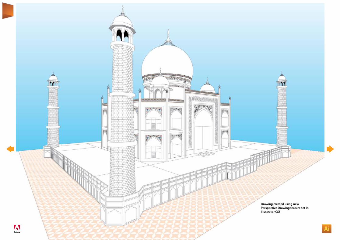
Drawing created using new Perspective Drawing feature set in Illustrator CS5
A d o b e I l l u s t r at o r C S 5 n 6 n P e r s p e c t i v e D r aw i n g
ILLUstrAtor Cs5DrAwIng the tAj In PerSPeCtIve
PerSPeCtIve (from Latin perspicere, to see through) is an approximate representation, on a flat surface (such as paper), of an image as it is seen by the eye. The two most characteristic
features of perspective are that objects are drawn: * Smaller as their distance from the observer increases * Foreshortened: the size of an object’s dimensions along the line
of sight are relatively shorter than dimensions across the line of sightAll perspective drawings assume the viewer is a certain distance
away from the drawing. Objects are scaled relative to that viewer. Additionally, an object is often not scaled evenly: a circle often appears as an ellipse and a square can appear as a trapezoid. This distortion is called foreshortening.
Perspective drawings typically have an—often implied—horizon line. This line, directly opposite the viewer’s eye, represents objects infinitely far away. They have shrunk, in the distance, to the infinitesimal thickness of a line. It is analogous to (and named after) the earth’s horizon.
Any perspective representation of a scene that includes parallel lines has one or more vanishing points in a perspective drawing. A one-point perspective drawing means that the drawing has a single vanishing point, usually (though not necessarily) directly opposite the viewer’s eye and usually (though not necessarily) on the horizon line. All lines parallel with the viewer’s line of sight recede to the horizon towards this vanishing point. This is the standard “receding railroad tracks” phenomenon. A two-point drawing would have lines parallel to two different angles. Any number of vanishing points are possible in a drawing, one for each set of parallel lines that are at an angle relative to the plane of the drawing.
Of the many types of perspective drawings, the most common are one-, two- and three-point. The names of these categories refer to the number of vanishing points in the perspective drawing.
One vanishing point is typically used for roads, railway tracks, hallways, or buildings viewed so that the front is directly facing the viewer. Any objects that are made up of lines either directly parallel
with the viewer’s line of sight or directly perpendicular (the railroad slats) can be represented with one-point perspective.
One-point perspective exists when the painting plate (also known as the picture plane) is parallel to two axes of a rectilinear (or Cartesian) scene—a scene which is composed entirely of linear elements that intersect only at right angles. If one axis is parallel with the picture plane, then all elements are either parallel to the painting plate (either horizontally or vertically) or perpendicular to it. All elements that are parallel to the painting plate are drawn as parallel lines. All elements that are perpendicular to the painting plate converge at a single point (a vanishing point) on the horizon.
two-point perspective can be used to draw the same objects as one-point perspective, rotated: looking at the corner of a house, or looking at two forked roads shrink into the distance, for example. One point represents one set of parallel lines, the other point represents the other. Looking at a house from the corner, one wall would recede towards one vanishing point, the other wall would recede towards the opposite vanishing point.
Three-point perspective is usually used for buildings seen from above (or below). In addition to the two vanishing points from before, one for each wall, there is now one for how those walls recede into the ground. This third vanishing point will be below the ground. Looking up at a tall building is another common example of the third vanishing point. This time the third vanishing point is high in space.
Three-point perspective exists when the perspective is a view of a Cartesian scene where the picture plane is not parallel to any of the scene’s three axes. each of the three vanishing points corresponds with one of the three axes of the scene. Image constructed using multiple vanishing points.
One-point, two-point, and three-point perspectives appear to embody different forms of calculated perspective. The methods required to generate these perspectives by hand are different. Mathematically, however, all three are identical: The difference is simply in the relative orientation of the rectilinear scene to the viewer.
seCtIoN-1: PersPeCtIve drAwINg BAsICs
Perspective: An Artist’s System of Representing Space
A d o b e I l l u s t r at o r C S 5 n 7 n P e r s p e c t i v e D r aw i n g
ILLUstrAtor Cs5DrAwIng the tAj In PerSPeCtIve
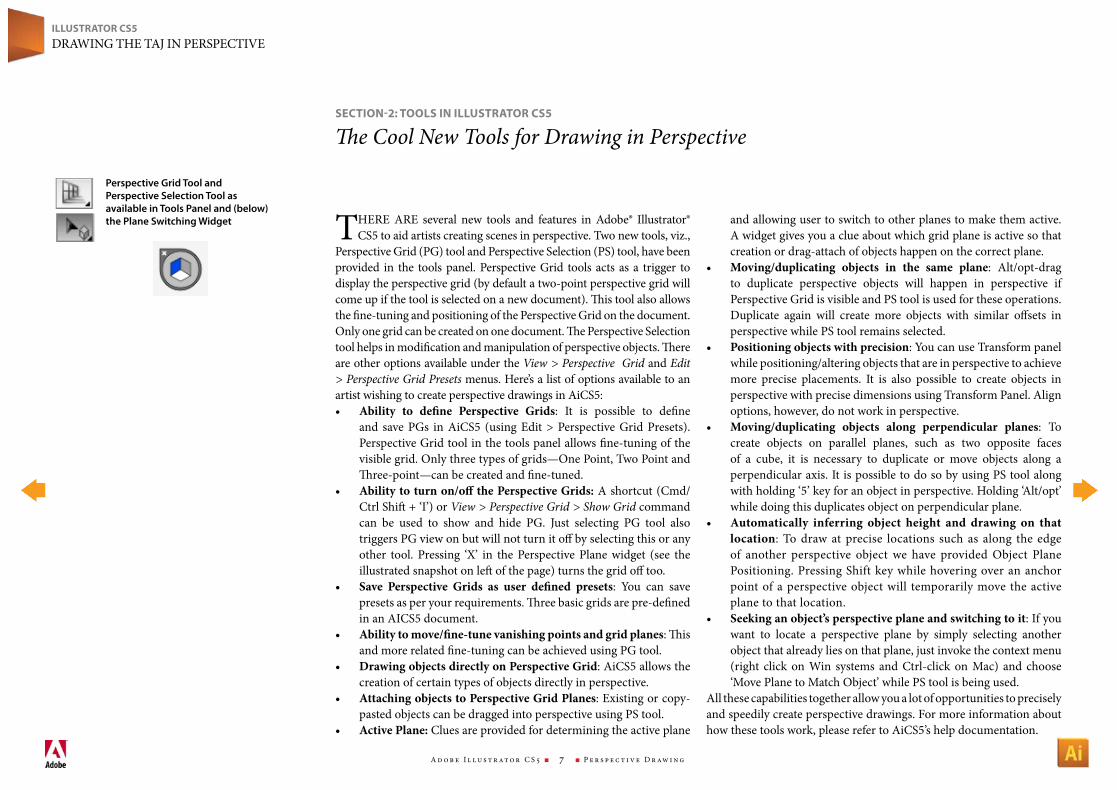
there Are several new tools and features in Adobe® Illustrator® CS5 to aid artists creating scenes in perspective. two new tools, viz.,
Perspective grid (Pg) tool and Perspective Selection (PS) tool, have been provided in the tools panel. Perspective grid tools acts as a trigger to display the perspective grid (by default a two-point perspective grid will come up if the tool is selected on a new document). This tool also allows the fine-tuning and positioning of the Perspective grid on the document. Only one grid can be created on one document. The Perspective Selection tool helps in modification and manipulation of perspective objects. There are other options available under the View > Perspective Grid and Edit > Perspective Grid Presets menus. here’s a list of options available to an artist wishing to create perspective drawings in AiCS5:• Ability to define Perspective Grids: It is possible to define
and save Pgs in AiCS5 (using edit > Perspective grid Presets). Perspective grid tool in the tools panel allows fine-tuning of the visible grid. Only three types of grids—One Point, two Point and Three-point—can be created and fine-tuned.
• Abilitytoturnon/offthePerspectiveGrids: A shortcut (Cmd/Ctrl Shift + ‘I’) or View > Perspective Grid > Show Grid command can be used to show and hide Pg. just selecting Pg tool also triggers Pg view on but will not turn it off by selecting this or any other tool. Pressing ‘X’ in the Perspective Plane widget (see the illustrated snapshot on left of the page) turns the grid off too.
• Save Perspective Grids as user defined presets: You can save presets as per your requirements. Three basic grids are pre-defined in an AICS5 document.
• Abilitytomove/fine-tunevanishingpointsandgridplanes: This and more related fine-tuning can be achieved using Pg tool.
• DrawingobjectsdirectlyonPerspectiveGrid: AiCS5 allows the creation of certain types of objects directly in perspective.
• AttachingobjectstoPerspectiveGridPlanes: existing or copy-pasted objects can be dragged into perspective using PS tool.
• ActivePlane: Clues are provided for determining the active plane
and allowing user to switch to other planes to make them active. A widget gives you a clue about which grid plane is active so that creation or drag-attach of objects happen on the correct plane.
• Moving/duplicating objects in the same plane: Alt/opt-drag to duplicate perspective objects will happen in perspective if Perspective grid is visible and PS tool is used for these operations. Duplicate again will create more objects with similar offsets in perspective while PS tool remains selected.
• Positioningobjectswithprecision: You can use transform panel while positioning/altering objects that are in perspective to achieve more precise placements. It is also possible to create objects in perspective with precise dimensions using transform Panel. Align options, however, do not work in perspective.
• Moving/duplicating objects along perpendicular planes: to create objects on parallel planes, such as two opposite faces of a cube, it is necessary to duplicate or move objects along a perpendicular axis. It is possible to do so by using PS tool along with holding ‘5’ key for an object in perspective. holding ‘Alt/opt’ while doing this duplicates object on perpendicular plane.
• Automatically inferring object height and drawing on thatlocation: to draw at precise locations such as along the edge of another perspective object we have provided Object Plane Positioning. Pressing Shift key while hovering over an anchor point of a perspective object will temporarily move the active plane to that location.
• Seekinganobject’sperspectiveplaneandswitchingtoit: If you want to locate a perspective plane by simply selecting another object that already lies on that plane, just invoke the context menu (right click on win systems and Ctrl-click on Mac) and choose ‘Move Plane to Match Object’ while PS tool is being used.
All these capabilities together allow you a lot of opportunities to precisely and speedily create perspective drawings. For more information about how these tools work, please refer to AiCS5’s help documentation.
seCtIoN-2: tooLs IN ILLUstrAtor Cs5
The Cool New Tools for Drawing in Perspective
Perspective Grid Tool and Perspective Selection Tool as available in Tools Panel and (below) the Plane Switching Widget
A d o b e I l l u s t r at o r C S 5 n 8 n P e r s p e c t i v e D r aw i n g
ILLUstrAtor Cs5DrAwIng the tAj In PerSPeCtIve
Perspective [email protected] | 09 JANUARY, 2009
1
On Artboard Editing of Perspective Grid
1
2
3
4
5
6
7
89
10
1112
1
2
3
4
56
7
89
1011
12
Horizon level /Eye Level [HL]
Right Vanishing Point [RVP]
True height line
Left Vanishing Point [LVP]
Ground Level [GL]
Height of Horizon
LEFT & RIGHT VANISHING POINT
Moves only Horizontally. Moves along the Horizon axis, if we allow tilting of the grid. For three point perspective, the third point will move along it’s axis.
Free movement of the vanishing point will be required when user is trying to create a perspective grid based on a image. In such cases, free movement can be allowed using a modi�er key(SHIFT/ALT). Note: When VP is freely moved, the horizon line should also move along with the point as the VP always lies on the horizon line.
User can drag the vanishing point beyond the modi�er widget - 3. As user drags the widget 1 or widget 2, the widget 3 maintains a constant distance with the VP by moving along with VP.
Origin
Grid Size Ruler
Left grid plane control
Horizontal grid plane control
Right grid plane control
1 2
5
6
7
9
1011
8
3
3
3
44
12
1 2
HORIZON LINE
The horizon line can be moved only in the vertical direc-tion. The height of the horizon line from the ground livel is displayed in the smart guide readout.
TILTING: (Nice to Have)
Beyond the end widget, user should be able to tilt the entire perspective grid by tilting the horizon line.
5
TRUE HEIGHT LINE
True height line lies on the Picture plane . The origin of the ruler lies at the intersection of ‘True Height line’ and the ‘Ground Level’. This line does not have any interaction.
6 7 8
GRID PLANE CONTROL
Left, Right and Horizontal Planes
Click and dragging the widget will allow the user to position the grid plane at any desired location. Cmd+Click on this widget will toggle the grid visibility.
9
ORIGIN
Origin resides at the intersection of the True Line height and the Ground line. Origin can be moved to any desired location on the grid. Double clicking this origin will reset the origin point to the default location (behavior quite like our document rulers)
10
RULER
The left and right vanishing point rulers are displayed at the interesting of the Vanishing point grid and the horizon-tal grid. The vertcial rulers are shown at the intersection of the left and right vanishing grid. We can later see whether these needs to be moved to any desired location on the grid. In future, if we plan to have Guides, then those can be pulled from this ruler position.
11
GRID SIZE
Resize(increase/decrease) the Grid Size. The grid size should be shown in the smart guide readouts. Grids on all the planes will be of the same size. If we get requirement for di�erent grid size, then we might have to have 3 point for each plane.
12
EXTENT OF GRID
User can increase/decrease the grid extents (no of visible grid) using this widget.
4
GROUND LINE
The widget at the end of the Ground line lets user move the entire perspective grid.
12
12
Appropriate cursor needs to be used used for widget controls to communicate the behavior possible with the widget. Wherever measurement is involved, smart guide readouts must be provided.
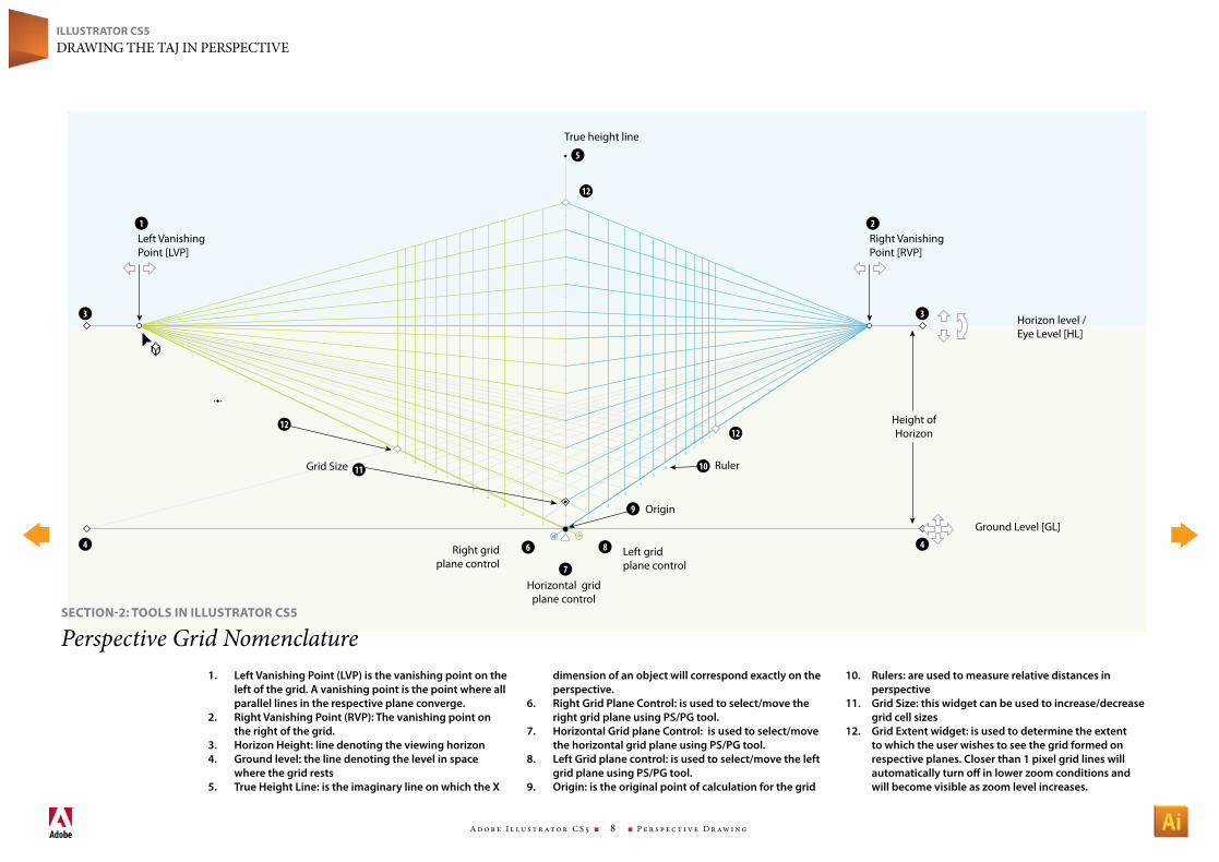
1. Left Vanishing Point (LVP) is the vanishing point on the left of the grid. A vanishing point is the point where all parallel lines in the respective plane converge.
2. Right Vanishing Point (RVP): The vanishing point on the right of the grid.
3. Horizon Height: line denoting the viewing horizon4. Ground level: the line denoting the level in space
where the grid rests5. True Height Line: is the imaginary line on which the X
dimension of an object will correspond exactly on the perspective.
6. Right Grid Plane Control: is used to select/move the right grid plane using PS/PG tool.
7. Horizontal Grid plane Control: is used to select/move the horizontal grid plane using PS/PG tool.
8. Left Grid plane control: is used to select/move the left grid plane using PS/PG tool.
9. Origin: is the original point of calculation for the grid
10. Rulers: are used to measure relative distances in perspective
11. Grid Size: this widget can be used to increase/decrease grid cell sizes
12. Grid Extent widget: is used to determine the extent to which the user wishes to see the grid formed on respective planes. Closer than 1 pixel grid lines will automatically turn off in lower zoom conditions and will become visible as zoom level increases.
seCtIoN-2: tooLs IN ILLUstrAtor Cs5
Perspective Grid Nomenclature
A d o b e I l l u s t r at o r C S 5 n 9 n P e r s p e c t i v e D r aw i n g
ILLUstrAtor Cs5DrAwIng the tAj In PerSPeCtIve
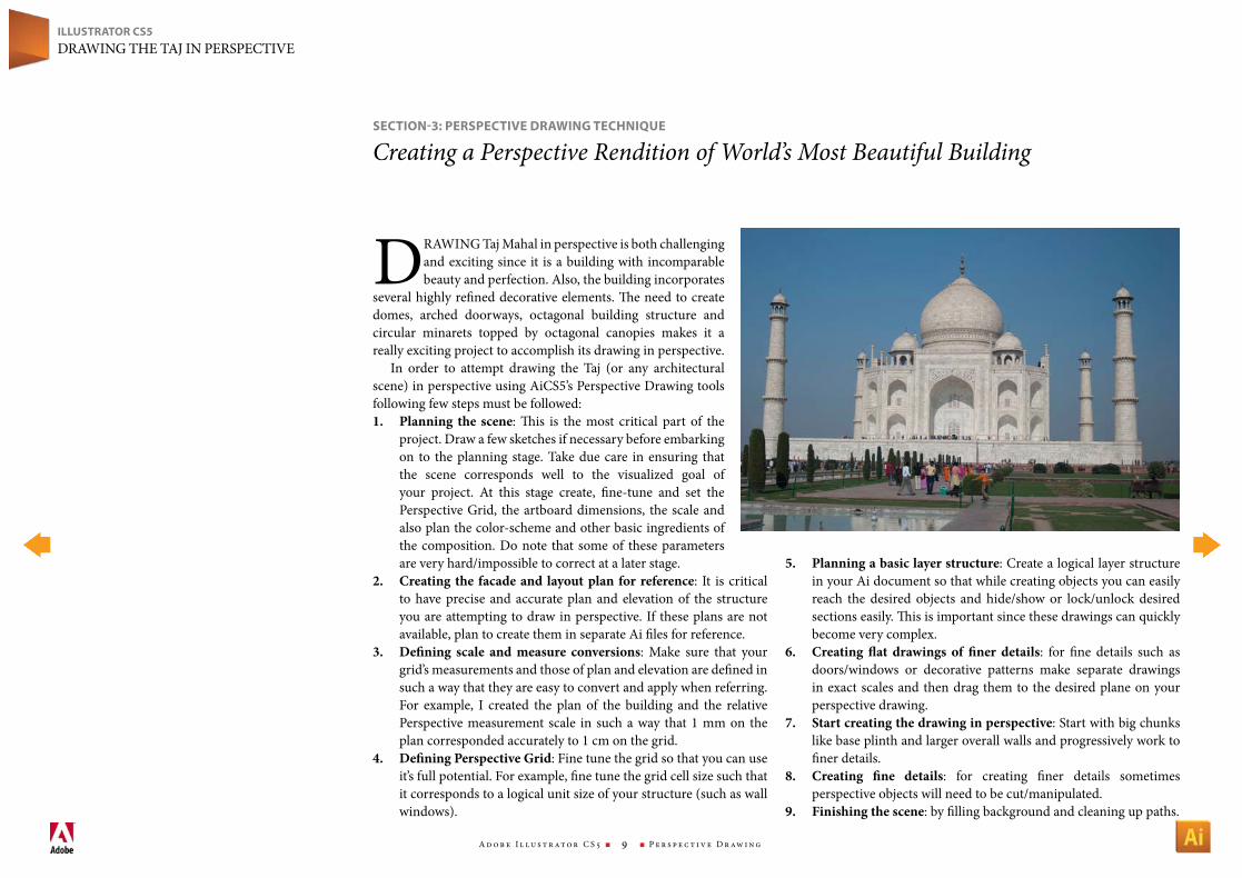
DrAwIng taj Mahal in perspective is both challenging and exciting since it is a building with incomparable beauty and perfection. Also, the building incorporates
several highly refined decorative elements. The need to create domes, arched doorways, octagonal building structure and circular minarets topped by octagonal canopies makes it a really exciting project to accomplish its drawing in perspective.
In order to attempt drawing the taj (or any architectural scene) in perspective using AiCS5’s Perspective Drawing tools following few steps must be followed:1. Planning the scene: This is the most critical part of the
project. Draw a few sketches if necessary before embarking on to the planning stage. take due care in ensuring that the scene corresponds well to the visualized goal of your project. At this stage create, fine-tune and set the Perspective grid, the artboard dimensions, the scale and also plan the color-scheme and other basic ingredients of the composition. Do note that some of these parameters are very hard/impossible to correct at a later stage.
2. Creatingthe facadeand layoutplanforreference: It is critical to have precise and accurate plan and elevation of the structure you are attempting to draw in perspective. If these plans are not available, plan to create them in separate Ai files for reference.
3. Defining scale andmeasure conversions: Make sure that your grid’s measurements and those of plan and elevation are defined in such a way that they are easy to convert and apply when referring. For example, I created the plan of the building and the relative Perspective measurement scale in such a way that 1 mm on the plan corresponded accurately to 1 cm on the grid.
4. DefiningPerspectiveGrid: Fine tune the grid so that you can use it’s full potential. For example, fine tune the grid cell size such that it corresponds to a logical unit size of your structure (such as wall windows).
5. Planningabasiclayerstructure: Create a logical layer structure in your Ai document so that while creating objects you can easily reach the desired objects and hide/show or lock/unlock desired sections easily. This is important since these drawings can quickly become very complex.
6. Creating flat drawings of finer details: for fine details such as doors/windows or decorative patterns make separate drawings in exact scales and then drag them to the desired plane on your perspective drawing.
7. Startcreatingthedrawinginperspective: Start with big chunks like base plinth and larger overall walls and progressively work to finer details.
8. Creating fine details: for creating finer details sometimes perspective objects will need to be cut/manipulated.
9. Finishingthescene: by filling background and cleaning up paths.
seCtIoN-3: PersPeCtIve drAwINg teCHNIqUe
Creating a Perspective Rendition of World’s Most Beautiful Building
A d o b e I l l u s t r at o r C S 5 n 1 0 n P e r s p e c t i v e D r aw i n g
ILLUstrAtor Cs5DrAwIng the tAj In PerSPeCtIve
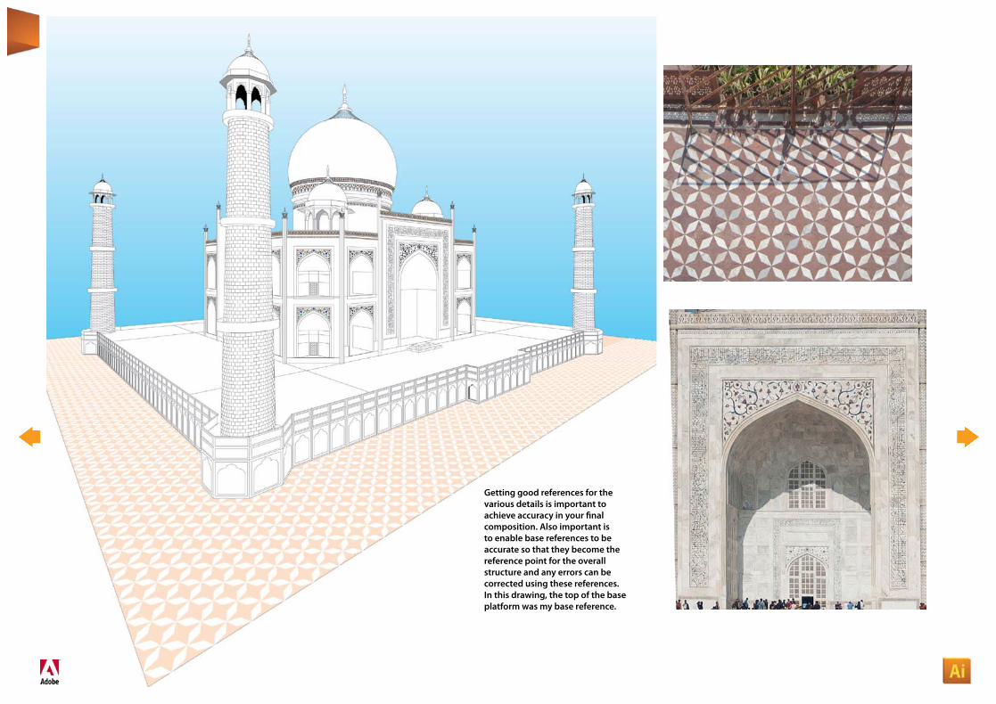
Getting good references for the various details is important to achieve accuracy in your final composition. Also important is to enable base references to be accurate so that they become the reference point for the overall structure and any errors can be corrected using these references. In this drawing, the top of the base platform was my base reference.
ILLUstrAtor Cs5DrAwIng the tAj In PerSPeCtIve
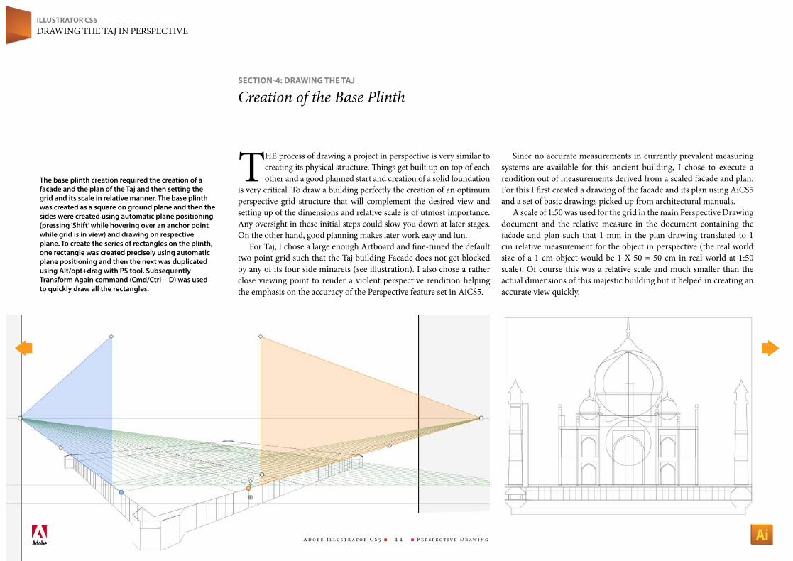
the process of drawing a project in perspective is very similar to creating its physical structure. Things get built up on top of each other and a good planned start and creation of a solid foundation
is very critical. to draw a building perfectly the creation of an optimum perspective grid structure that will complement the desired view and setting up of the dimensions and relative scale is of utmost importance. Any oversight in these initial steps could slow you down at later stages. On the other hand, good planning makes later work easy and fun.
For taj, I chose a large enough Artboard and fine-tuned the default two point grid such that the taj building Facade does not get blocked by any of its four side minarets (see illustration). I also chose a rather close viewing point to render a violent perspective rendition helping the emphasis on the accuracy of the Perspective feature set in AiCS5.
Since no accurate measurements in currently prevalent measuring systems are available for this ancient building, I chose to execute a rendition out of measurements derived from a scaled faćade and plan. For this I first created a drawing of the facade and its plan using AiCS5 and a set of basic drawings picked up from architectural manuals.
A scale of 1:50 was used for the grid in the main Perspective Drawing document and the relative measure in the document containing the faćade and plan such that 1 mm in the plan drawing translated to 1 cm relative measurement for the object in perspective (the real world size of a 1 cm object would be 1 X 50 = 50 cm in real world at 1:50 scale). Of course this was a relative scale and much smaller than the actual dimensions of this majestic building but it helped in creating an accurate view quickly.
seCtIoN-4: drAwINg tHe tAJ
Creation of the Base Plinth
The base plinth creation required the creation of a facade and the plan of the Taj and then setting the grid and its scale in relative manner. The base plinth was created as a square on ground plane and then the sides were created using automatic plane positioning (pressing ‘Shift’ while hovering over an anchor point while grid is in view) and drawing on respective plane. To create the series of rectangles on the plinth, one rectangle was created precisely using automatic plane positioning and then the next was duplicated using Alt/opt+drag with PS tool. Subsequently Transform Again command (Cmd/Ctrl + D) was used to quickly draw all the rectangles.
A d o b e I l l u s t r at o r C S 5 n 1 1 n P e r s p e c t i v e D r aw i n g
A d o b e I l l u s t r at o r C S 5 n 1 2 n P e r s p e c t i v e D r aw i n g
ILLUstrAtor Cs5DrAwIng the tAj In PerSPeCtIve
seCtIoN-4: drAwINg tHe tAJ
Creating the Basic Main Structure
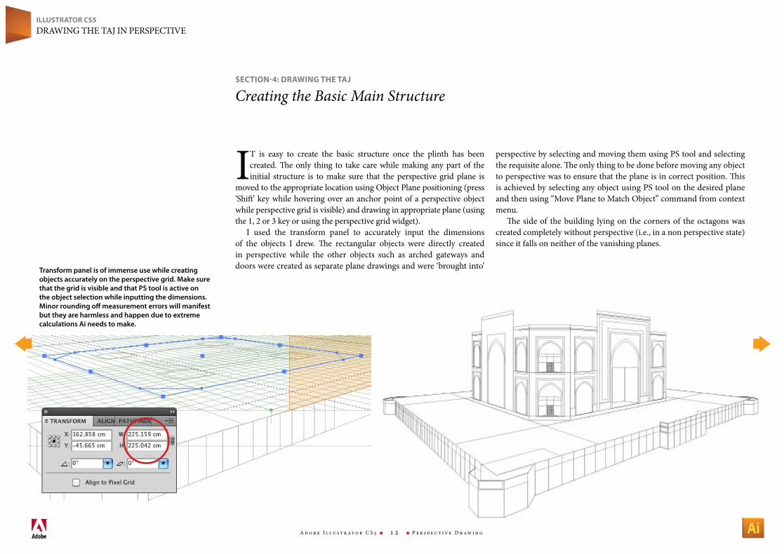
Transform panel is of immense use while creating objects accurately on the perspective grid. Make sure that the grid is visible and that PS tool is active on the object selection while inputting the dimensions. Minor rounding off measurement errors will manifest but they are harmless and happen due to extreme calculations Ai needs to make.
It is easy to create the basic structure once the plinth has been created. The only thing to take care while making any part of the initial structure is to make sure that the perspective grid plane is
moved to the appropriate location using Object Plane positioning (press ‘Shift’ key while hovering over an anchor point of a perspective object while perspective grid is visible) and drawing in appropriate plane (using the 1, 2 or 3 key or using the perspective grid widget).
I used the transform panel to accurately input the dimensions of the objects I drew. The rectangular objects were directly created in perspective while the other objects such as arched gateways and doors were created as separate plane drawings and were ‘brought into’
perspective by selecting and moving them using PS tool and selecting the requisite alone. The only thing to be done before moving any object to perspective was to ensure that the plane is in correct position. This is achieved by selecting any object using PS tool on the desired plane and then using “Move Plane to Match Object” command from context menu.
The side of the building lying on the corners of the octagons was created completely without perspective (i.e., in a non perspective state) since it falls on neither of the vanishing planes.
A d o b e I l l u s t r at o r C S 5 n 1 3 n P e r s p e c t i v e D r aw i n g
ILLUstrAtor Cs5DrAwIng the tAj In PerSPeCtIve
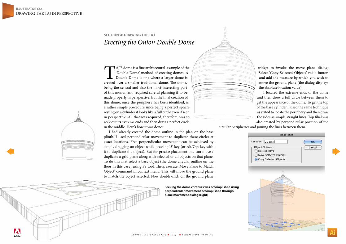
tAj’S dome is a fine architectural example of the ‘Double Dome’ method of erecting domes. A Double Dome is one where a larger dome is
created over a smaller traditional dome. The dome, being the central and also the most interesting part of this monument, required careful planning if to be made properly in perspective. But the final creation of this dome, once the periphery has been identified, is a rather simple procedure since being a perfect sphere resting on a cylinder it looks like a full circle even if seen in perspective. All that was required, therefore, was to seek out its extreme ends and then draw a perfect circle in the middle. here’s how it was done:
I had already created the dome outline in the plan on the base plinth. I used perpendicular movement to duplicate these circles at exact locations. Free perpendicular movement can be achieved by simply dragging an object while pressing ‘5’ key (or Alt/Opt key with it to duplicate the object). But for precise placement one can move /duplicate a grid plane along with selected or all objects on that plane. to do this first select a base object (the dome circular outline on the floor in this case) using PS tool. Then, execute ‘Move Plane to Match Object’ command in context menu. This will move the ground plane to match the object selected. now double-click on the ground plane
widget to invoke the move plane dialog. Select ‘Copy Selected Objects’ radio button and add the measure by which you wish to move the ground plane (the dialog displays the absolute location value).
I located the extreme ends of the dome and then drew a full circle between them to get the appearance of the dome. to get the top of the base cylinder, I used the same technique as stated to locate the periphery and then draw the sides as simple straight lines. top filial was also created by perpendicular position of the
circular peripheries and joining the lines between them.
seCtIoN-4: drAwINg tHe tAJ
Erecting the Onion Double Dome
Seeking the dome contours was accomplished using perpendicular movement accomplished through plane movement dialog (right)
A d o b e I l l u s t r at o r C S 5 n 1 4 n P e r s p e c t i v e D r aw i n g
ILLUstrAtor Cs5DrAwIng the tAj In PerSPeCtIve
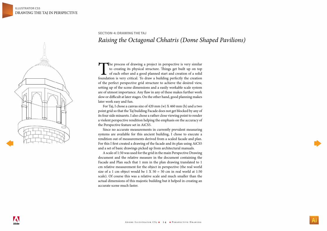
the process of drawing a project in perspective is very similar to creating its physical structure. Things get built up on top of each other and a good planned start and creation of a solid
foundation is very critical. to draw a building perfectly the creation of the perfect perspective grid structure to achieve the desired view, setting up of the scene dimensions and a easily workable scale system are of utmost importance. Any flaw in any of these makes further work slow or difficult at later stages. On the other hand, good planning makes later work easy and fun.
For taj, I chose a canvas size of 420 mm (w) X 460 mm (h) and a two point grid so that the taj building Facade does not get blocked by any of its four side minarets. I also chose a rather close viewing point to render a violent perspective rendition helping the emphasis on the accuracy of the Perspective feature set in AiCS5.
Since no accurate measurements in currently prevalent measuring systems are available for this ancient building, I chose to execute a rendition out of measurements derived from a scaled facade and plan. For this I first created a drawing of the facade and its plan using AiCS5 and a set of basic drawings picked up from architectural manuals.
A scale of 1:50 was used for the grid in the main Perspective Drawing document and the relative measure in the document containing the Facade and Plan such that 1 mm in the plan drawing translated to 1 cm relative measurement for the object in perspective (the real world size of a 1 cm object would be 1 X 50 = 50 cm in real world at 1:50 scale). Of course this was a relative scale and much smaller than the actual dimensions of this majestic building but it helped in creating an accurate scene much faster.
seCtIoN-4: drAwINg tHe tAJ
Raising the Octagonal Chhatris (Dome Shaped Pavilions)
A d o b e I l l u s t r at o r C S 5 n 1 5 n P e r s p e c t i v e D r aw i n g
ILLUstrAtor Cs5DrAwIng the tAj In PerSPeCtIve
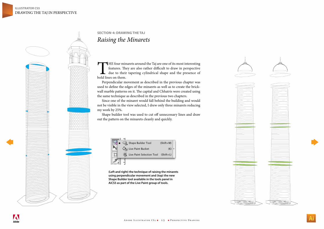
the four minarets around the taj are one of its most interesting features. They are also rather difficult to draw in perspective due to their tapering cylindrical shape and the presence of
bold lines on them.Perpendicular movement as described in the previous chapter was
used to define the edges of the minarets as well as to create the brick-wall marble patterns on it. The capital and Chhatris were created using the same technique as described in the previous two chapters.
Since one of the minaret would fall behind the building and would not be visible in the view selected, I drew only three minarets reducing my work by 25%.
Shape builder tool was used to cut off unnecessary lines and draw out the pattern on the minarets cleanly and quickly.
seCtIoN-4: drAwINg tHe tAJ
Raising the Minarets
(Left and right) the technique of raising the minarets using perpendicular movement and (top) the new Shape Builder tool available in the tools panel in AiCS5 as part of the Live Paint group of tools.
A d o b e I l l u s t r at o r C S 5 n 1 6 n P e r s p e c t i v e D r aw i n g
ILLUstrAtor Cs5DrAwIng the tAj In PerSPeCtIve
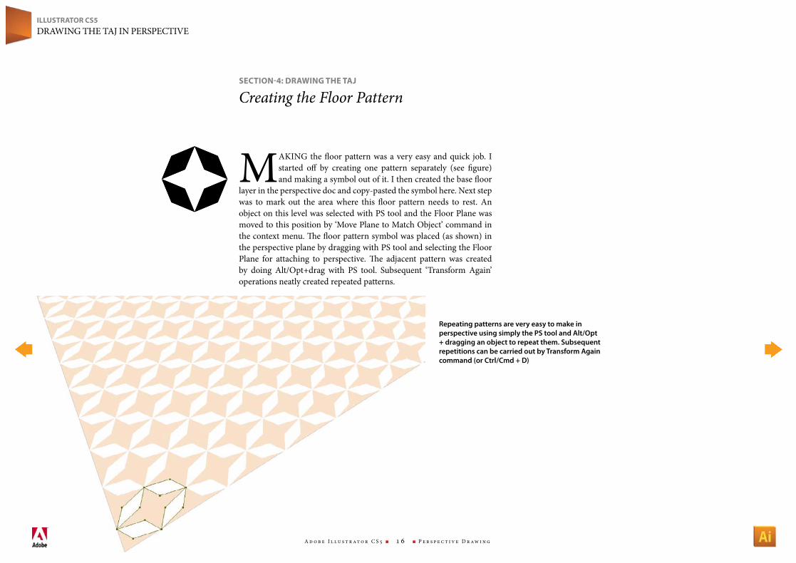
MAkIng the floor pattern was a very easy and quick job. I started off by creating one pattern separately (see figure) and making a symbol out of it. I then created the base floor
layer in the perspective doc and copy-pasted the symbol here. next step was to mark out the area where this floor pattern needs to rest. An object on this level was selected with PS tool and the Floor Plane was moved to this position by ‘Move Plane to Match Object’ command in the context menu. The floor pattern symbol was placed (as shown) in the perspective plane by dragging with PS tool and selecting the Floor Plane for attaching to perspective. The adjacent pattern was created by doing Alt/Opt+drag with PS tool. Subsequent ‘transform Again’ operations neatly created repeated patterns.
seCtIoN-4: drAwINg tHe tAJ
Creating the Floor Pattern
Repeating patterns are very easy to make in perspective using simply the PS tool and Alt/Opt + dragging an object to repeat them. Subsequent repetitions can be carried out by Transform Again command (or Ctrl/Cmd + D)
A d o b e I l l u s t r at o r C S 5 n 1 7 n P e r s p e c t i v e D r aw i n g
ILLUstrAtor Cs5DrAwIng the tAj In PerSPeCtIve
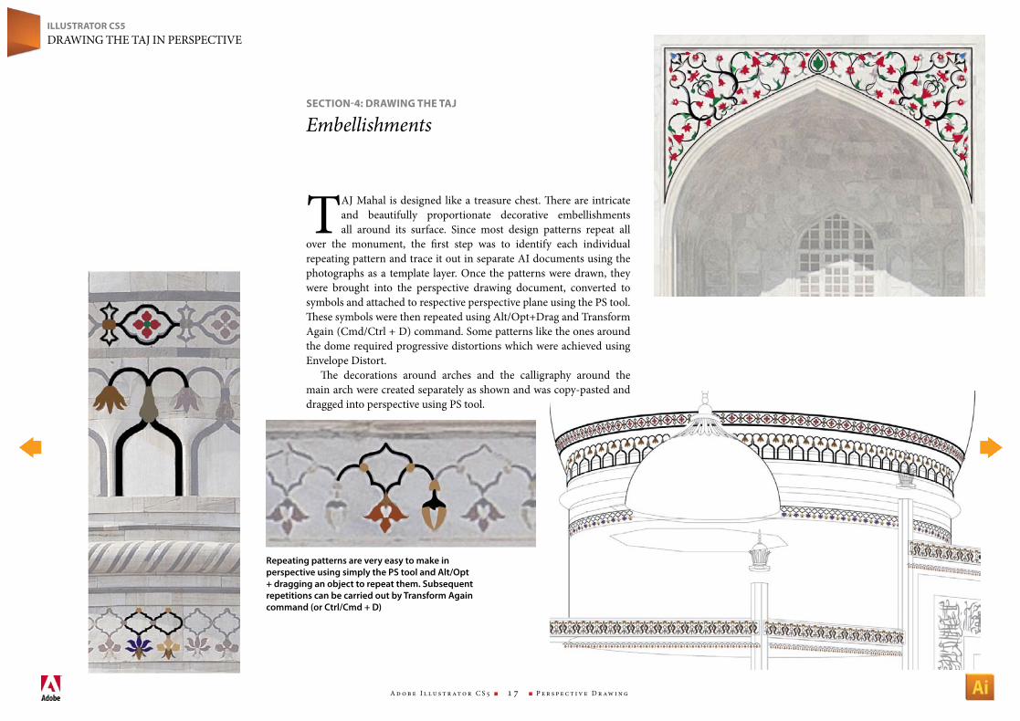
tAj Mahal is designed like a treasure chest. There are intricate and beautifully proportionate decorative embellishments all around its surface. Since most design patterns repeat all
over the monument, the first step was to identify each individual repeating pattern and trace it out in separate AI documents using the photographs as a template layer. Once the patterns were drawn, they were brought into the perspective drawing document, converted to symbols and attached to respective perspective plane using the PS tool. These symbols were then repeated using Alt/Opt+Drag and transform Again (Cmd/Ctrl + D) command. Some patterns like the ones around the dome required progressive distortions which were achieved using envelope Distort.
The decorations around arches and the calligraphy around the main arch were created separately as shown and was copy-pasted and dragged into perspective using PS tool.
seCtIoN-4: drAwINg tHe tAJ
Embellishments
Repeating patterns are very easy to make in perspective using simply the PS tool and Alt/Opt + dragging an object to repeat them. Subsequent repetitions can be carried out by Transform Again command (or Ctrl/Cmd + D)
A d o b e I l l u s t r at o r C S 5 n 1 8 n P e r s p e c t i v e D r aw i n g
ILLUstrAtor Cs5DrAwIng the tAj In PerSPeCtIve
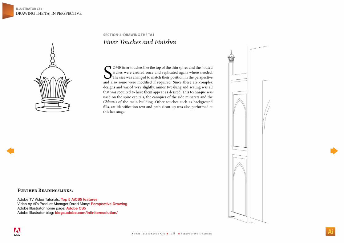
SOMe finer touches like the top of the thin spires and the flouted arches were created once and replicated again where needed. The size was changed to match their position in the perspective
and also some were modified if required. Since these are complex designs and varied very slightly, minor tweaking and scaling was all that was required to have them appear as desired. This technique was used on the spire capitals, the canopies of the side minarets and the Chhatris of the main building. Other touches such as background fills, art identification text and path clean-up was also performed at this last stage.
seCtIoN-4: drAwINg tHe tAJ
Finer Touches and Finishes
FurtherReading/links:
Adobe TV Video Tutorials: Top 5 AiCS5 featuresVideo by Ai’s Product Manager David Macy: Perspective DrawingAdobe Illustrator home page: Adobe CS5Adobe Illustrator blog: blogs.adobe.com/infiniteresolution/
Perspective Drawing Using Adobe® Illustrator® CS5
M ay 2 0 1 0