Personal FM Transceivers - NCJRS FM TRANSCEIVERS 1. PURPOSE AND SCOPE ... frequency modulated ......
36
LS. Department of Justice Sational Institute of Justice Personal FM Transceivers NIJ Standard 0209.01
Transcript of Personal FM Transceivers - NCJRS FM TRANSCEIVERS 1. PURPOSE AND SCOPE ... frequency modulated ......
LS. Department of Justice Sational Institute of Justice
Personal FM Transceivers NIJ Standard 0209.01

ABOUT THE TECHNOLOGY ASSESSMENT PROGRAM
The Technology Assessment Program is sponsored by the Office of Development, Testing, and Dissem- ination of the National Institute of Justice (NIJ), U.S. Department of Justice. The program responds to the mandate of the Justice System Improvement Act of 1979, which created NIJ and directed it to encourage research and development to improve the criminal justice system and to disseminate the results to Federal, - . State, and local agencies.
The Technology Assessment Program is an applied research effort that determines the technological needs of justice system agencies, sets minimum performance standards for specific devices, tests commercially - -
available equipment against those standards, and disseminates the standards and the test results to criminal justice agencies nationwide and internationally.
The program operates through: The Technology Assessment Program Advisory Council (TAPAC) consisting of nationally recognized crim-
inal justice practitioners from Federal, State, and local agencies, which assesses technological needs and sets priorities for research programs and items to be evaluated and tested.
The Law Enforcement Standards Laboratoy (LESL) at the National Bureau of Standards, which develops voluntary national performance standards for compliance testing to ensure that individual items of equipment are suitable for use by criminal justice agencies. The standards are based upon laboratory testing and evaluation of representative samples of each item of equipment to determine the key attributes, develop test methods, and establish minimum performance requirements for each essential attribute. In addition to the highly technical standards, LESL also produces user guides that explain in nontechnical terms the capabilities of available equipment.
The Technology Assessment Program Information Center (TAPIC) operated by the International Associ- ation of Chiefs of Police (IACP), which supervises a national compliance testing program conducted by independent agencies. The standards developed by LESL serve as performance benchmarks against which commercial equipment is measured. The facilities, personnel, and testing capabilities of the independent laboratories are evaluated by LESL prior to testing each item of equipment, and LESL helps, the Information Center staff review and analyze data. Test results are published in Consumer Product Reports designed to help justice system procurement officials make informed purchasing decisions.
Publications issued by the National Institute of Justice, including those of the Technology Assessment Program, are available from the National Criminal Justice Reference Service (NCJRS), which serves as a central information and reference source for the Nation's criminal justice community. For further information on how to order, o r to register with NCJRS, write to the National Institute of Justice, National Criminal Justice Reference Service, Washington, D C 2053 1.
James K. Stewart, Director National Institute. of Justice
U.S. Department of Justice
National Institute of Justice
Technology Assessment Program
Personal FM Transceivers
NIJ Standard 0209.01
September 1985
U.S. DEPARTMENT OF JUSTICE National Institute of Justice
James K. Stewart, Director
ACKNOWLEDGMENTS
Thisstandard was formulated by the Law Enforcement Standards Laboratory of the National Bureau of Standards under the direction of Marshall J. Treado. Program Manager for Communications Systems, and Lawrence K. Eliason, Chief of LESL. NBS Electromagnetic Fields Division staff members responsible for the preparation of this standard were Ramon Jesch, Bill Bensema and Art Wainright. Acknowledgment is given to previous work in this field by the Associated Public-Safety Communications Officers, Inc. and the Electronic Industries Association. This standard has been reviewed and approved by the Technology Assessment Program Advisory Council and adopted by the International Association of Chiefs of Police (IACP) as an IACP Standard.

FOREWORD
This document, NU Standard-0209.01, Personal FM Transceivers, is an equipment standard developed by the Law Enforcement Standards Laboratory of the National Bureau of Standards. It is produced as part of the Technology Assessment Program of the National Institilte of Justice. A brief description of the program appears on the inside front cover.
This standard is a technical document that specifies performance and other requirements equipment should meet to satisfy the needs of criminal justice agencies for high quality service. Purchasers can use the test
. . methods described in this standard to determine whether a particular piece of equipment meets the essential requirements, or they may have the tests conducted on their behalf by a qualified testing laboratory. Pro- curement officials may also refer to this standard in their purchasing documents and require that equipment offered for purchase meet the requirements. Compliance with the requirements of the standard may be attested to by an independent laboratory or guaranteed by the vendor.
Because this NIJ standard is designed as a procurement aid, it is necessarily highly technical. For those who seek general guidance concerning the selection and application of law enforcement equipment, user guides have also been published. The guides explain in nontechnical language how to select equipment capable of the performance required by an agency.
NIJ standards are subjected to continuing review. Technical comments and recommended revisions are welcome. Please send suggestions to the Program Manager for Standards, National Institute of Justice, U.S. Department of Justice, Washington, DC 2053 1.
Before citing this or any other NIJ standard in a contract document, users should verify that the most recent edition of the standard is used. Write to: Chief, Law Enforcement Standards Laboratory, National Bureau of Standards, Gaithersburg, MD 20899.
Lester D. Shubin Program Manager for Standards National Institute of Justice
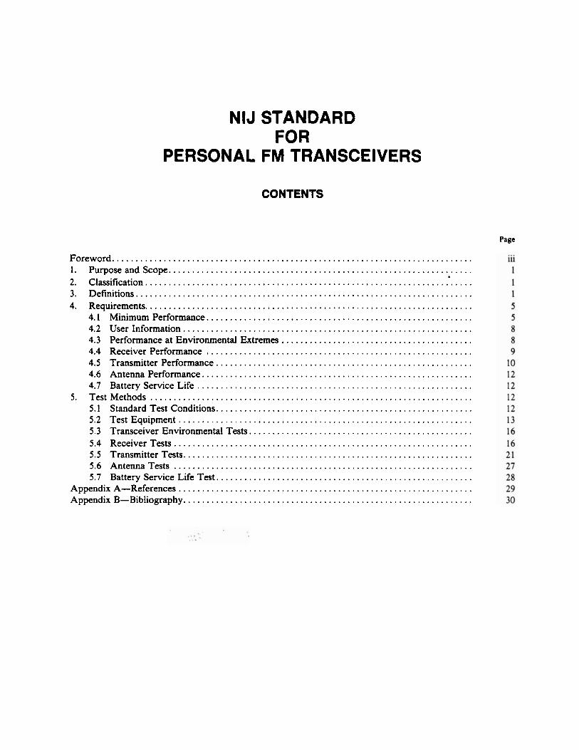
NlJ STANDARD FOR
PERSONAL FM TRANSCEIVERS
CONTENTS
Page
Foreword . . . . . . . . . . . . . . . . . . . . . . . . . . . . . . . . . . . . . . . . . . . . . . . . . . . . . . . . . . . . . . . . . . . . . . . . . . . . . 1 . PurposeandScope . . . . . . . . . . . . . . . . . . . . . . . . . . . . . . . . . . . . . . . . . . . . . . . . . . . . . . . . . . . . . . . . . 2 . Classification . . . . . . . . . . . . . . . . . . . . . . . . . . . . . . . . . . . . . . . . . . . . . . . . . . . . . . . . . . . . . . . . . . . . . . 3 . Definitions . . . . . . . . . . . . . . . . . . . . . . . . . . . . . . . . . . . . . . . . . . . . . . . . . . . . . . . . . . . . . . . . . . . . . . . . 4 . Requirements . . . . . . . . . . . . . . . . . . . . . . . . . . . . . . . . . . . . . . . . . . . . . . . . . . . . . . . . . . . . . . . . . . . . . .
4.1 Minimum Performance . . . . . . . . . . . . . . . . . . . . . . . . . . . . . . . . . . . . . . . . . . . . . . . . . . . . . . . . . 4.2 User Information . . . . . . . . . . . . . . . . . . . . . . . . . . . . . . . . . . . . . . . . . . . . . . . . . . . . . . . . . . . . . .
. . . . . . . . . . . . . . . . . . . . . . . . . . . . . . . . . . . . . . . . . 4.3 Performance at Environmental Extremes 4.4 Receiver Performance . . . . . . . . . . . . . . . . . . . . . . . . . . . . . . . . . . . . . . . . . . . . . . . . . . . . . . . . . 4.5 Transmitter Performance . . . . . . . . . . . . . . . . . . . . . . . . . . . . . . . . . . . . . . . . . . . . . . . . . . . . . . . 4.6 AntennaPerfomance . . . . . . . . . . . . . . . . . . . . . . . . . . . . . . . . . . . . . . . . . . . . . . . . . . . . . . . . . . 4.7 Battery Service Life . . . . . . . . . . . . . . . . . . . . . . . . . . . . . . . . . . . . . . . . . . . . . . . . . . . . . . . . . . .
5 . Test Methods . . . . . . . . . . . . . . . . . . . . . . . . . . . . . . . . . . . . . . . . . . . . . . . . . . . . . . . . . . . . . . . . . . . . . 5.1 Standard Test Conditions . . . . . . . . . . . . . . . . . . . . . . . . . . . . . . . . . . . . . . . . . . . . . . . . . . . . . . . 5.2 Test Equipment . . . . . . . . . . . . . . . . . . . . . . . . . . . . . . . . . . . . . . . . . . . . . . . . . . . . . . . . . . . . . . . 5.3 Transceiver Environmental Tests . . . . . . . . . . . . . . . . . . . . . . . . . . . . . . . . . . . . . . . . . . . . . . . . 5.4 Receiver Tests . . . . . . . . . . . . . . . . . . . . . . . . . . . . . . . . . . . . . . . . . . . . . . . . . . . . . . . . . . . . . . . . 5.5 Transmitter Tests . . . . . . . . . . . . . . . . . . . . . . . . . . . . . . . . . . . . . . . . . . . . . . . . . . . . . . . . . . . . . . 5.6 AntennaTests . . . . . . . . . . . . . . . . . . . . . . . . . . . . . . . . . . . . . . . . . . . . . . . . . . . . . . . . . . . . . . . . 5.7 Battery Service Life Test . . . . . . . . . . . . . . . . . . . . . . . . . . . . . . . . . . . . . . . . . . . . . . . . . . . . . . .
Appendix A-References . . . . . . . . . . . . . . . . . . . . . . . . . . . . . . . . . . . . . . . . . . . . . . . . . . . . . . . . . . . . . . . AppendixB-Bibliography . . . . . . . . . . . . . . . . . . . . . . . . . . . . . . . . . . . . . . . . . . . . . . . . . . . . . . . . . . . . . .

NIJ Standardd209.01
NIJ STANDARD FOR
PERSONAL FM TRANSCEIVERS
1. PURPOSE AND SCOPE
The purpose of this document is to establish performance requirements and methods of test for nontrunked frequency modulated (FM) personal transceivers and their associated antennas and power sources. This standard applies to transceivers which either do not have special subsystems such as selective signaling or voice privacy, or in which such subsystems are bypassed or disabled during testing for compliance with this standard. This standard supersedes NILECJ - STD -0209.00 Personal FM Transceivers.
2. CLASSIFICATION
For the purpose of this standard, personal FM transceivers are classified by their operating frequencies.
2.1 Type I
Transceivers which operate in the 25-50 MHz band with a receiver channel spacing of 20 kHz.
2.2 Type It
Transceivers which operate in the 150-174 MHz band with a receiver channel spacing of 30 kHz.
2.3 Type Ill
Transceivers which operate in the 400-512 MHz band with a receiver channel spacing of 25 kHz.
2.4 Type IV
Transceivers which operate in the 806-866 MHz band with a receiver channel spacing of 25 kHz.
3. DEFINITIONS
The principal terms used in this document are defined in this section. Additional definitions relating to law enforcement communicatiosis~&re given in LESP-RPT-0203.00, Technical Terms and Definitions Used with Law Enforcement Communications Equipment [l] '. 3.1 Adjacent - Channel Selectivity and Desensitization
The ability of a receiver to discriminate against a signal at the frequency of an adjacent channel.
3.2 AM Hum and Noise The residual amplitude modulation present on an unmodulated carrier.
3.3 Audio Harmonic Distortion
Nonlinear distortion characterized by the appearance in the output of integral multiples of an audio- frequency input signal.
'~urnbers in brackets refer to references in appendix A.
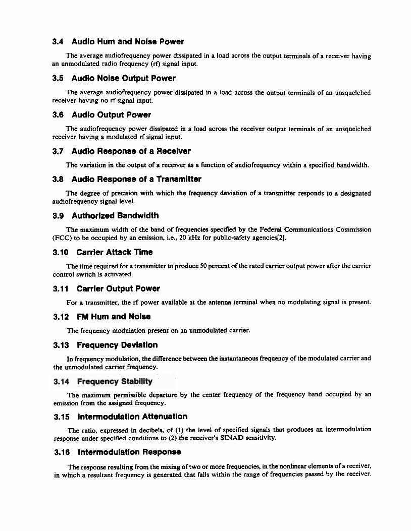
3.4 Audio Hum and Noise Power
The average audiofrequency power dissipated in a load across the output terminals of a receiver having an unmodulated radio frequency (rf) signal input.
3.5 Audio Noise Output Power
The average audiofrequency power dissipated in a load across the output terminals of an unsquelched receiver having no rf signal input.
3.6 Audio Output Power
The audiofrequency power dissipated in a load across the receiver output terminals of an unsquelched receiver having a modulated rf signal input.
3.7 Audio Response of a Receiver
The variation in the output of a receiver as a function of audiofrequency within a specified bandwidth.
3.8 Audio Response of a Transmitter
The degree of precision with which the frequency deviation of a transmitter responds to a designated audiofrequency signal level.
3.9 Authorized Bandwidth
The maximum width of the band of frequencies specified by the Federal Communications Commission (FCC) to be occupied by an emission, i.e., 20 kHz for public-safety agencies[2].
3.10 Carrier Attack Time
The time required for a transmitter to produce 50 percent of the rated carrier output power after the carrier control switch is activated.
3.1 1 Carrier Output Power
For a transmitter, the rf power available at the antenna terminal when no modulating signal is present.
3.12 FM Hum and Noise
The frequency modulation present on an unmodulated carrier.
3.1 3 Frequency Deviation
In frequency modulation, the difference between the instantaneous frequency of the modulated camer and the unmodulated carrier frequency.
3.14 Frequency Stability -
The maximum permissible departure by the center frequency of the frequency band occupied by an emission from the assigned frequency.
3.1 5 lntermodulation Attenuation
The ratio, expressed in decibels, of (1) the level of specified signals that produces an intermodulation response under specified conditions to (2) the receiver's SINAD sensitivity.
3.1 6 lntermodulation Response
The response resulting from the mixing of two or more frequencies, in the nonlinear elements of a receiver, in which a resultant frequency is generated that falls within the range of frequencies passed by the receiver.
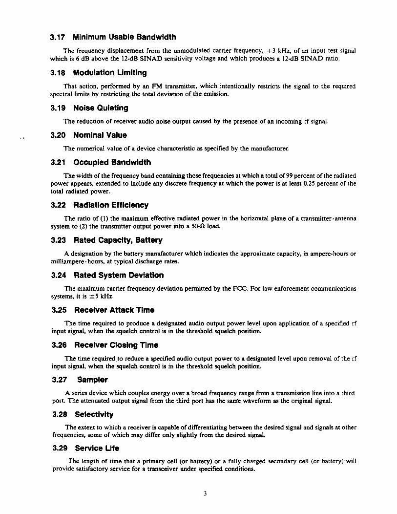
3.17 Minimum Usable Bandwidth
The frequency displacement from the unmodulated carrier frequency, + 3 kHz, of an input test signal which is 6 dB above the 12dB SINAD sensitivity voltage and which produces a 12-dB SINAD ratio.
3.18 Modulation Limiting
That action, performed by an FM transmitter, which intentionally restricts the signal to the required spectral limits by restricting the total deviation of the emission.
3.19 Noise Quieting
The reduction of receiver audio noise output caused by the presence of an incoming rf signal.
. , 3.20 Nominal Value
The numerical value of a device characteristic as specified by the manufacturer.
3.21 Occupied Bandwidth
The width of the frequency band containing those frequencies at which a total of 99 percent of the radiated power appears, extended to include any discrete frequency at which the power is at least 0.25 percent of the total radiated power.
3.22 Radiation Eff lciency
The ratio of (1) the maximum effective radiated power in the horizontal plane of a transmitter-antenna system to (2) the transmitter output power into a 5 0 4 load.
3.23 Rated Capacity, Battery
A designation by the battery manufacturer which indicates the approximate capacity, in ampere-hours or milliampere- hours, at typical discharge rates.
3.24 Rated System Deviation
The maximum camer frequency deviation permitted by the FCC. For law enforcement communications systems, it is f 5 kHz.
3.25 Receiver Attack Tlme
The time required to produce a designated audio output power level upon application of a specified rf input signal, when the squelch control is in the threshold squelch position.
3.26 Receiver Closing Time
The time required.to reduce a specified audio output power to a designated level upon removal of the rf input signal, when the squelch control is m the threshold squelch position.
3.27 Sampler
A series device which couples energy over a broad frequency range from a transmission line into a third port. The attenuated output signal from the third port has the sanfe whveform as the original signal.
3.28 Selectivity
The extent to which a receiver is capable of differentiating between the desired signal and signals at other frequencies, some of which may differ only slightly from the desired signal.
3.29 Service Life
The length of time that a primary cell (or battery) or a fully charged secondary cell (or battery) will provide satisfactory service for a transceiver under specified conditions.
3.30 Sideband Spectrum
The emissions generated by a modulated transmitter that are within 250 percent of the authorized band- width, i.e., +_25 kHz.
3.31 SlNAD Ratio
The ratio, expressed in decibels, of (1) signal plus noise plus distortion to (2) noise plus distortion produced at the output of a receiver; from SIgnal Noise And Distortion Ratio.
3.32 SlNAD Sensitivity
The minimum modulated rf signal input level required to produce a specified SINAD ratio at a specified audio output power level. . -
3.33 Spurious Emission
Any part of the rf output that is not a component of the theoretical output or exceeds the authorized bandwidth.
3.34 Spurious and Harmonic Response
The output of a receiver caused by a signal at a frequency other than that to which the receiver is tuned.
3.35 Squelch
A circuit function for preventing a receiver from producing audio output power in the absence of an rf input signal.
3.36 Squelch Block
A squelched condition resulting from excessive frequency deviation due to a specified rf modulated input signal.
3.37 Standby Mode
The condition of a transceiver when it is energized but not receiving or transmitting.
3.38 Standing Wave Ratio (SWR)
The ratio of the maximum to the minimum amplitudes of the voltage or current appearing along a transmission line.
3.39 Threshold Squelch Position
The adjustmdnt of the-sqpelch Control, starting from the maximum unsquelched position, that first reduces the audio noise output power by a specified amount.
3.40 Threshold Squelch Sensitivity
The minimum standard modulated rf signal input level required to unsquelch a receiver when the squelch control is in the threshold squelch position.
3.41 Tight Squelch Sensitivity
The minimum standard modulated rfsignal input level required to unsquelch a receiver when the squelch control is in the maximum squelch position.
3.42 Transceiver
The combination of radio transmitting and receiving equipment in a common housing, usually for portable or mobile use.
REQUIREMENTS
4.1 Minimum Performance
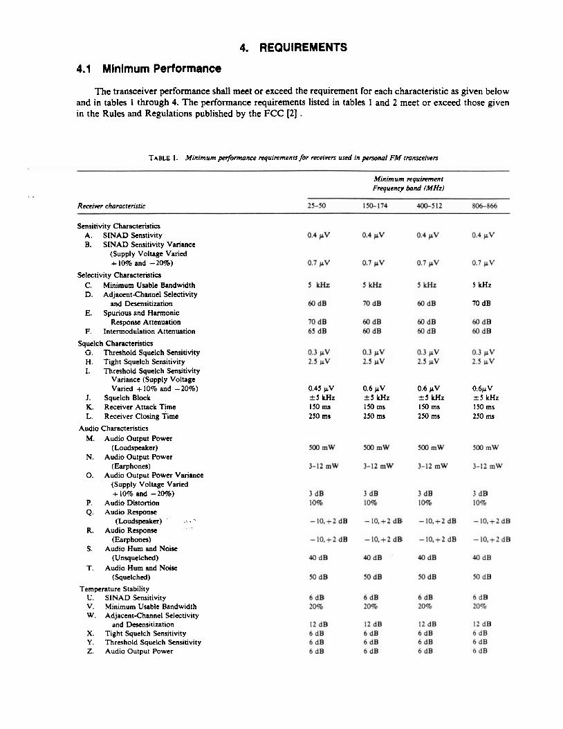
The transceiver performance shall meet or exceed the requirement for each characteristic as given below and in tables 1 through 4. The performance requirements listed in tables 1 and 2 meet or exceed those given in the Rules and Regulations published by the FCC [2] .
TABLE 1. Minimum performance requirements for receivers used in personal FM transceivers
Minimum requirement Frequency band (MHz)
. . Receiver characteristic 25-50 150-174 400-512 806-866
Sensitivity Characteristics A. SINAD Senstivity B. SINAD Sensitivity Variance
(Supply Voltage Varied + 10% and - 20%)
Selectivity Characteristics C. Minimum Usable Bandwidth D. Adjacent-Channel Selectivity
and Desensitization E. Spurious and Harmonic
Response Attenuation F. Intermodulation Attenuation
5 kHz 5 kHz 5 kHz
Squelch Characteristics G. Threshold Squelch Sensitivity H. Tight Squelch Sensitivity I. Threshold Squelch Sensitivity
Variance (Supply Voltage Varied + 10% and - 20%)
J. Squelch Block K. Receiver Attack Time L. Receiver Closing Time
0.45 pV *5 kHz 150 ms 250 ms
0.6 pV +5 kHz 150 ms 250 ms
0.6 p V 2 5 kHz I50 ms 250 ms
0.6pV 2 5 kHz 150 rns 250 ms
Audio Characteristics M. Audio Output Power
(Loudspeaker) N. Audio Output Power
(Earphones) 0. Audio Output Power Variance
(Supply Voltage Varied + 10% and - 20%)
P. Audio Distortion Q. Audio Response
(Loudspeaker) ' .;. " R. Audio Response . .
(Earphones) S. Audio Hum and Noise
(Unsquelched) T. Audio Hum and Noise
(Squelched)
Temperature Stability U. SINAD Sensitivity V. Minimum Usable Bandwidth W. Adjacent-Channel Selectivity
and Desensitization X. Tight Squelch Sensitivity Y. Threshold Squelch Sensitivity Z. Audio Output Power

TABLE I. ,Uinimum perfannance requirements for receivers uscd in personal F M tmnrceivers-Continued
Mtnimum rcgvirement Frequency band (MHz)
Receiver chamcteristic 25-50 150-174 400-512 806-866
AA. Audio Hum and Noise AB. Audio Distortion
Humidity Stability AC. SINAD Sensitivity AD. Minimum Usable Bandwidth AE. Adjacent-Channel Selectivity
and Desensitization AF. Tight Squelch Sensitivity AG. Threshold Squelch Smsitivity AH. Audio Output Power AI. Audio Hum and Noise AJ. Audio Distortion
TABLE 2. Minimum performance requircmcnn for transmitters used in perso~l FM t m n s c e i ~
Minimum rrquikment Frequency bond (MHz)
Transmitter characteristic
Radio Frequency Carrier Characteristics BA. Carrier Output Power Variance BB. Output Power Variance
(Supply Voltage Varied f 10%) BC. Output Power Variance
(Supply Voltage Varied -20%) BD. Carrier Frequency Tolerance BE. Frequency Stability
(Supply Voltage Varied f 15%) BF. AM Hum and Noise Level BG. Camer Attack Time
Audio Modulation Characteristics BH. Audio Hannonic Distortion BI. FM Hum and Noise Level BJ. Audio Response BK. Frequency Deviation BL. Modulation Limiting .; ' '1
.. .
5 70 40 dB +-I,-3 dB 5% 2 5 kHz
5% 40 dB + I,-3 dB 5% k 5 kHz
5% 40 dB +I,-3 dB 5% 2 5 kHz
5% 40 dB +I,-3 dB 5% f 5 kHz
Electromagnetic Compatibility Charactcristia BM. Radiated Spurious Emissions BN. Sideband Spectrum ( 2 10 kHz Frequency
Separation) BO. Sideband Spectrum ( c 2 0 LHr Frequency
Separation)
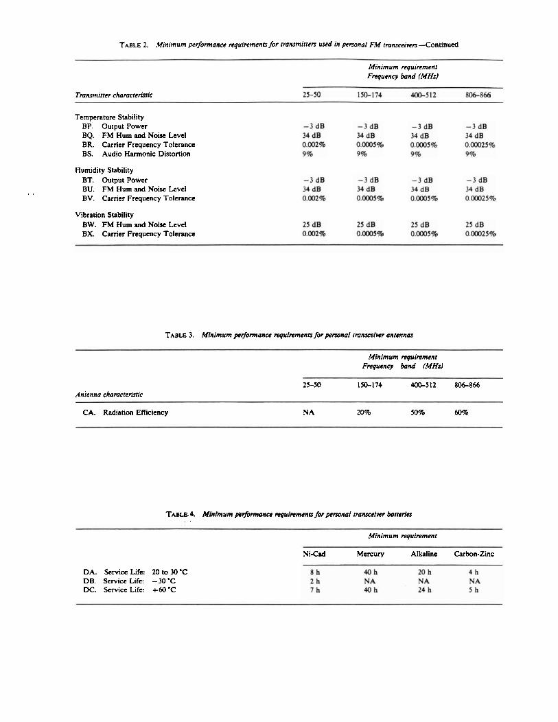
TABLE 2. Minimum performance requirements for rmnsmitten used in personal FM rmnsceiven-Continued
Minimum requirement Frequency band (MHz)
Tmnsmitter chamcteristic 25-50 150-174 400-512 806-866
Temperature Stability BP. Output Power BQ. FM Hum and Noise Level BR. Carrier Frquency Tolerance BS. Audio Harmonic Distortion
Humidity Stability BT. Output Power
. . BU. FM Hum and Noise Level BV. Carrier Frquency Tolerance
Vibration Stability BW. FM Hum and Noise Level BX. Carrier Frquency Tolerance
TABLE 3. Minimum petfonnance reguircments for personal tmnreeiwr antennas
- -
Minimum requirement Fregueney band (MHz)
Anrenna chamcteristic
CA. Radiation Efficiency N A 20% 50% 60%
TABLE 4. Mhimum perfbrmance mpircmena for personal tnansceiver batteries . .
Minimum requirement
Ni-Cad Mercury Alkaline Carbon-Zinc
DA. Service Life: 2 0 to 30 'C DB. Service Life: -30 'C DC. Service Life: + 60 'C
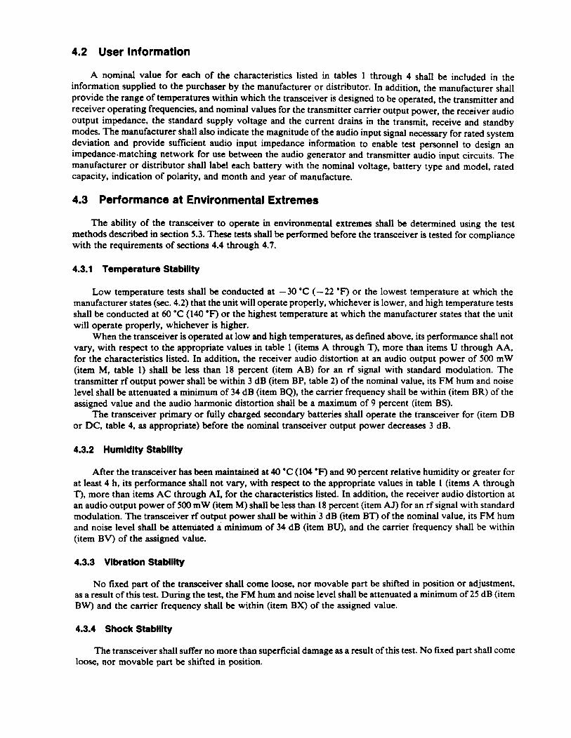
4.2 User Information
A nominal value for each of the characteristics listed in tables 1 through 4 shall be included in the information supplied to the purchaser by the manufacturer or distributor. In addition, the manufacturer shall provide the range of temperatures within which the transceiver is designed to be operated, the transmitter and receiver operating frequencies, and nominal values for the transmitter carrier output power, the receiver audio output impedance, the standard supply voltage and the current drains in the transmit, receive and standby modes. The manufacturer shall also indicate the magnitude of the audio input signal necessary for rated system deviation and provide sufficient audio input impedance information to enable test personnel to design an impedance.matching network for use between the audio generator and transmitter audio input circuits. The manufacturer or distributor shall label each battery with the nominal voltage, battery type and model, rated capacity, indication of polarity, and month and year of manufacture.
4.3 Performance at Environmental Extremes
The ability of the transceiver to operate in environmental extremes shall be determined using the test methods described in section 5.3. These tests shall be performed before the transceiver is tested for compliance with the requirements of sections 4.4 through 4.7.
4.3.1 Temperature Stability
Low temperature tests shall be conducted at - 30 "C (- 22 O F ) or the lowest temperature at which the manufacturer states (sec. 4.2) that the unit will operate properly, whichever is lower, and high temperature tests shall be conducted at 60 'C (140 'F) or the highest temperature at which the manufacturer states that the unit will operate properly, whichever is higher.
When the transceiver is operated at low and high temperatures, as defined above, its performance shall not vary, with respect to the appropriate values in table 1 (items A through T), more than items U through AA, for the characteristics listed. In addition, the receiver audio distortion at an audio output power of 500 mW (item M, table 1) shall be less than 18 percent (item AB) for an rf signal with standard modulation. The transmitter rf output power shall be within 3 dB (item BP, table 2) of the nominal value, its FM hum and noise level shall be attenuated a minimum of 34 dB (item BQ), the carrier frequency shall be within (item BR) of the assigned value and the audio harmonic distortion shall be a maximum of 9 percent (item BS).
The transceiver primary or fully charged secondary batteries shall operate the transceiver for (item DB or DC, table 4, as appropriate) before the nominal transceiver output power decreases 3 dB.
4.3.2 Humldlty Stablllty
After the transceiver has been maintained at 40 'C (104 "F) and 90 percent relative humidity or greater for at least 4 h, its performance shall not vary, with respect to the appropriate values in table 1 (items A through T), more than items A C through AI, for the characteristics listed. In addition, the receiver audio distortion at an audio output power of 500 mW (item M) shall be less than. 18 percent (item AJ) for an rf signal with standard modulation. The transceiver rf output power shall be within 3 dB (item BT) of the nominal value, its FM hum and noise level shall be attenuated a minimum of 34 dB (item BU), and the carrier frequency shall be within (item BV) of the assigned value.
4.3.3 Vibration Stability
No fixed part of the transceiver shall come loose, nor movable part be shifted in position or adjustment, as a result of this test. During the test, the FM hum and noise level shall be attenuated a minimum of 25 dB (item BW) and the carrier frequency shall be within (item BX) of the assigned value.
4.3.4 Shock Stability
The transceiver shall suffer no more than superficial damage as a result of this test. No fixed part shall come loose, nor movable part be shifted in position.
4.4 Receiver Performance
4.4.1 SlNAD Sensitivity
When measured in accordance with section 5.4.1, the SINAD sensitivity of the receiver shall be 0.4 p,V (item A) or less at a SINAD ratio of 12 dB and an audio output power of at least 50 percent of 500 mW, i.e., 250 mW. When the standard power supply voltage is varied + 10 percent and -20 percent, the SINAD sensitivity shall be 0.7 pV (item B) or less.
4.4.2 Selectivity Characteristics
The selectivity characteristics of minimum usable bandwidth, adjacent-channel selectivity and desensi- tization, spurious and harmonic response attenuation, and intermodulation attenuation shall be measured in accordance with section 5.4.2.
. . 4.4.2.1 Minimum Usable Bandwidth
The minimum usable bandwidth of the receiver shall be no less than 5 kHz (item C) for an applied rf signal 6 dB above the measured 12dB SINAD sensitivity value.
4.4.2.2 Adjacent-Channel Selectivity and Desensitization
The adjacent-channel selectivity and desensitization of the receiver shall be (item D) or more for a degradation of an on-channel signal from 12dB SINAD ratio to 6-dB SINAD ratio caused by an adjacent- channel signal.
4.4.2.3 Spurious and Harmonic Response Attenuation
The spurious and harmonic response attenuation of the receiver shall be (item E) or more as compared to the on-channel 20 dB noisequieting signal voltage for responses of the receiver between the lowest inter- mediate frequency of the receiver and at least twice the receiver operating frequency, or 1000 MHz, whichever is higher.
4.4.2.4 Intermodulation Attenuation
The intermodulation attenuation of the receiver shall be (item F) or more for a degradation of an on-channel signal from 12dB SINAD ratio to 6-dB SINAD ratio by two relatively strong signals located at one- and two-channel spacings, respectively, from the receiver frequency, both signals being at frequencies either above or below the onchannel signal.
4.4.3 Squelch Characteristics
The squelch characteristics of sensitivity, block, receiver attack time, and receiver closing time shall be measured in accordance with section 5.4.3.
4.4.3.1 Squelch Sensitivity
The threshold squelch semitiuity of the receiver shall be 0.3 pV (item G) or less. The tight squelch sensitivity shall be 2.5 pV (it& H) or 1ess:When the standard power supply voltage is varied + 10 percent and -20 percent, the threshold squelch sensitivity shall be (item I) or less.
4.4.3.2 Squelch Block
The receiver shall not squelch for modulation frequencies of 0.3 to 3 kHz when the squelch control is adjusted to the maximum squelch position and the frequency deviation of the input signal is + 5 kHz (item J) or less.
4.4.3.3 Receiver Attack Time
The time for the receiver to produce an audio output power of 90 percent of 500 mW, i.e., 450 mW, shall be 150 ms (item K) or less.
4.4.3.4 Receiver Closing Time
The time for the audio output power of the receiver to decrease to 10 percent of 500 mW, i.e., 50 mW, shall be 250 ms (item L) or less.
4.4.4 Audio Characteristics
The audio characteristics of output power, distortion, response, and hum and noise shall be measured in accordance with section 5.4.4.
4.4.4.1 Audio Output Power
The audio output power of the receiver shall be at least 500 mW (item M) if a loudspeaker is used at the receiver output and at least 3 mW but not greater than 12 mW (item N) if earphones are used. When the standard supply voltage is varied + 10 percent and -20 percent, the audio output power shall not be reduced more than 3 dB (item 0) below 500 mW.
4.4.4.2 Audio Distortion
Audio distortion at audio output powers of 500 mW (loudspeaker) and 3-12 mW (earphones) shall be less than 10 percent (item P) for an rf input signal with standard modulation.
4.4.4.3 A udio Response
The audio response of the receiver, when used with a loudspeaker, shall be within - 10, + 2 dB (item Q) of an ideal 6 dB per octave de-emphasis curve with constant frequency deviation at frequencies between 0.3 and 3 kHz, with the exception that a 6 dB per octave roll-off from 600 to 300 Hz may be present. When used with earphones, the audio response of the receiver shall also be within - 10, +2 dB (item R) of the same curve at frequencies between 0.3 and 3 kHz, with the exception that a 6 dB per octave roll-off from 600 to 300 Hz may be present.
4.4.4.4 Audio Hum and Noise
The audio hum and noise output power from the receiver in the unsquelched condition shall be 40 dB (item S) or more, and in the maximum squelched condition, shall be 50 dB (item T) or more below an audio output power of 500 mW.
4.5 Transmitter Performance
4.5.1 Radio Frequency Characteristics
The radio frequency camer characteristics of output power, frequency stability, AM hum and noise level, and carrier attack time shall be measured in accordance with section 5.5.1.
4.5.1.1 Output Power
Transmitter output power is specified by the FCC [2] . When the transceiver is in the transmit mode, the carrier output power delivered to a standard output load shall not decrease more than 0.3 dB (item BA) from the nominal value at any time during the standard test duty cycle, except for the initial second after the transceiver has been switched from the standby mode to the transmit mode. When the standard supply voltage is varied + 10 percent, the output power shall not decrease by more than 3 dB (item BB). When the standard supply voltage is reduced by 20 percent, the output power shall not decrease by more than 6 dB (item BC).
4.5.1.2 Frequency Stability
The camer frequency shall be within (item BD) of the assigned value at all times during the transceiver test duty cycle that the transceiver is in the transmit mode, except for the initial second after the transceiver has been switched from the standby mode to the transmit mode. When the standard supply voltage is varied k 15 percent, the carrier frequency shall be maintained within (item BE) of the assigned value.
4.5.1.3 AM Hum and Noise Level
The AM hum and noise level shall be attenuated a minimum of 34 dB (item BF) below the unmodulated nominal carrier output power level.
4.5.1.4 Carrier Attack Time
The carrier output power shall increase to 50 percent of its nominal value in less than 100 ms (item BG).
4.5.2 Audio Moduiatlon Characteristics
The audio modulation characteristics of harmonic distortion, FM hum and noise level, response, fre- quency deviation, and modulation limiting shall be measured in accordance with section 5.5.2.
4.5.2.1 Audio Harmonic Distortion
The audio harmonic distortion shall be a maximum of 5 percent (item BH).
4.5.2.2 FM Hum and Noise Level
The FM hum and noise level shall be attenuated a minimum of 40 dB (item BI).
4.5.2.3 Audio Response
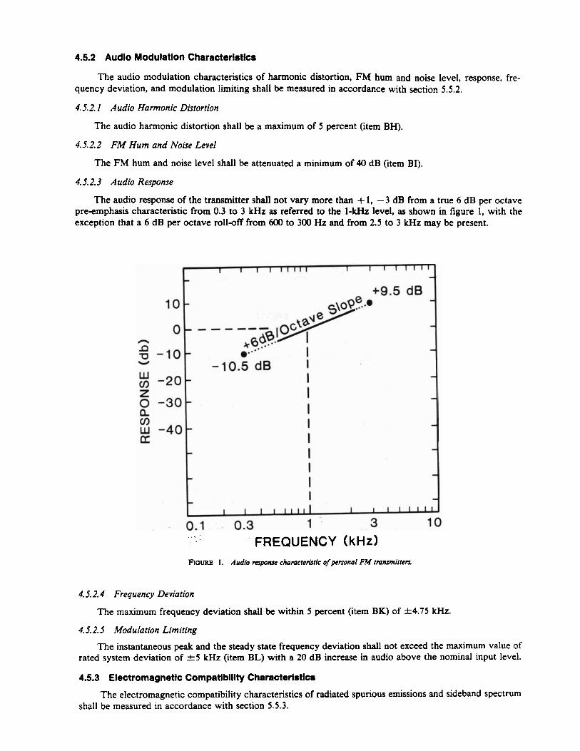
The audio response of the transmitter shall not vary more than + 1, -3 dB from a true 6 dB per octave pre-emphasis characteristic from 0.3 to 3 kHz as referred to the 1-kHz level, as shown in figure 1, with the exception that a 6 dB per octave roll-off from 600 to 300 Hz and from 2.5 to 3 kHz may be present.
FIGURE 1 . Audw response chamcteristic of personal FM tmnrmitters
10
0 h
a u -10- V
: -20 z 0 -30 a a W -40 u
4.5.2.4 Frequency Deviation
The maximum frequency deviation shall be within 5 percent (item BK) of t4.75 kHz.
1 1 1 I 1 1 1 1 1 1 I 1 1 1 1 1 1 -. -
+9.5 dB - S \ ~ ~ e . .. -
- - - - --- - (30. a?.. I&' ." - I
-10.5 dB I - I d
- I - I
- I - I - - I I -
P I I - -
I I I I l l l l l I I I 1 1 1 1 1
4.5.2.5 Modulation Limiting
. - 0-1 . 0.3 1 '. 3 10 . . . . . FREQUENCY (kHz)
The instantaneous peak and the steady state frequency deviation shall not exceed the maximum value of rated system deviation of f 5 kHz (item BL) with a 20 dB increase in audio above the nominal input level.
4.5.3 Electromagnetic Compatibility Characteristics
The electromagnetic compatibility characteristics of radiated spurious emissions and sideband spectrum shall be measured in accordance with section 5.5.3.
4.5.3.1 Radiated Spurious Emissions
Each radiated spurious emission shall be attenuated a minimum of [43 (item BM)+ 10 loglo (output power in watts)] dB below the nominal field strength of the carrier, i.e., each radiated spurious emission shall be less than 50 pW.
4.5.3.2 Sideband Spectrum
Each spurious sideband emission shall be attenuated greater than (item BN) when the frequency is separated from the assigned carrier by + 10 kHz, and shall be attenuated greater than (item BO) when the frequency is separated from the assigned carrier by &20 kHz.
4.6 Antenna Performance
4.6.1 Radiation Efficiency
When measured in accordance with section 5.6.1, the radiation eficiency shall be (item CA, table 3) or greater.
4.7 Battery Service Life When tested in accordance with section 5.7, each primary or fully-charged secondary battery shall
operate the transceiver for (item DA) before the nominal transmitter output power decreases 3 dB. See also the high and low temperature service life requirements given in section 4.3.1.1.
5. TEST METHODS
5.1 Standard Test Conditions Allow all measurement equipment to warm up until the system has achieved sufficient stability to perform
the measurement. Unless otherwise specified, perform all measurements under standard test conditions.
5.1.1 Standard Temperature
Standard ambient temperature shall be between 20 and 30 "C (68 and 86 OF).
5.1.2 Standard Relatlve Humldlty
Standard ambient relative humidity shall be between 10 and 85 percent.
5.1.3 Standard Supply Voltage
The standard supply voltage shall be the nominal battery voltage as specified by the manufacturer in accordance with section 4.2. Tests shall be performed using either a battery of the same type as normally used in the equipment or a well-filtered electronic dc supply. In the latter case, it shall be adjusted to within one percent of the voltage required.
5.1.4 Standard Test .Frequendes
The standard test frequencies shall be the transmitter and the receiver operating frequencies.
5.1.5 Standard Test Modulation
5.1.5. I Audio Test Modulation
Audio test modulation shall be a 1-kHz signal (from a source with distortion less than 1%) at the level required to produce 60 percent of rated system deviation (i.e., f 3 kHz).
5.1.5.2 Electromagnetic Compatibility Test Modulation
Electromagnetic compatibility test modulation shall be a 2.5 kHz sine wave at an input level 16 dB greater than that required to produce 50 percent of rated system deviation at 1 kHz.
5.1.6 Rated System Deviation
Rated system deviation shall be f 5 kHz.
5.1.7 Standard Squelch Adjustment
The squelch control shall be adjusted to the maximum unsquelch position for all receiver measurements except where otherwise specified.
5.1.8 Standard Duty Cycles
5. I. 8.1 Transceiver Test Duty Cycle
The tran'sceiver test duty cycle shall be 2 min in the transmit mode followed by 3 min in the standby mode.
5.1.8.2 Battery Test Duty Cycle
The battery test duty cycle will be 6 s in the transmit mode, 6 s in the receive mode, and 48 s in the standby mode.
5.1.9 Standard Radiation Test Site
5.1.9.1 Type Z and I . Transceivers
The standard radiation test site shall be located on level ground which has uniform electrical character- istics (i.e., ground constants). Reflecting objects (especially large metal objects), trees, buildings, and other objects which would perturb the electromagnetic fields to be measured should not be located closer than 90 m (295 ft) from any test equipment or equipment under test. All utility lines and any control circuits between test positions should be buried underground. The ambient electrical noise level shall be as low as possible and shall be carefully monitored to ensure that it does not interfere with the test being performed.
5.1.9.2 Type IZZ and ZV Transceivers
In addition to the requirements described in 5.1.9.1, the standard radiation test site shall have microwave absorbing material placed on the ground between the transceiver and the receiving antenna to restrict st'anding waves, produced by reflections from the ground, to no larger than + 1 dB. If available, an anechoic chamber may be used instead (sec. 5.2.18).
5.1.10 Standard Charge
Prior to testing, each secondary battery shall be discharged to a voltage of 1 V per cell at a current of C o r less, where C is numerically equal to the battery rated capacity in ampere-hours or milliampere-hours. Slow-charge batteries shall then be recharged at a rate of 0.1 C for 14 to 16 h. Fastcharge batteries shall be fully recharged in accordance with the manufacturer's instructions.
5.2 Test Equipment
The test equipment discusmfha thissection is limited to that equipment which is the most critical in making the measurements di&ssed in this btandard. All other test equipment shall be of comparable quality.
5.2.1 Environmental Chamber(s)
The environmental chamber(s) shall produce air temperatures from -30 to 60 "C (-22 to 140 OF) and relative humidities in the range of 90 to 95 percent. The test item shall be shielded' from air currents blowing directly from heating or cooling elements in the chamber. The temperature of the test item shall be measured with a thermometer separate from the sensor used to control the chamber air temperature. Likewise, humidity shall be measured with a hygrometer separate from the sensor used to control humidity.
5.2.2 Vibration Tester
The vibration tester shall be adjustable in frequency from 10 to 60 Hz, in a linear-sweep mode, and it shall be servo-controlled, with a reference signal derived from a suitable calibrated accelerometer or other calibrated sensor. It shall also provide an adjustable simple harmonic motion in at least one plane for a total excursion of 0.04 in (1 mm).
5.2.3 FM Signal Generator b
The FM signal generator shall have a 50-R output impedance, a maximum SWR of 1.2 and a calibrated variable output level accurate to -1-2 dB when terminated in a 56-R load. It shall also have a single sideband 1-Hz bandwidth phase noise less than - 135 dB below the carrier at 25 kHz separation for carrier frequencies of 500 MHz and lower (- 130 dB at 900 MHz). The generator should include a digital frequency counter having an uncertainty no greater than one part in lo6, and a deviation monitor or calibrated control for determining the peak frequency deviation with an uncertainty no greater than 5 percent. If an integral frequency counter is not included, a separate frequency counter having the required accuracy shall be provided. Three of these are required..
5.2.4 CW Sweep Signal Generator
The CW sweep signal generator shall have the same characteristics as the FM signal generator except that the FM capability and the low phase noise capability are not required. The sweep generator should have some . - means of slowly, automatically sweeping the frequency band, especially for the higher frequencies.
5.2.5 Distortion Analyzer
The distortion analyzer shall have a required input level of between 1 and 5 V rms, an input impedance of at least 50,000 R shunted by less than 100 pF, and an accuracy of at least + 1 dB. It shall have the capability to measure both audio distortion and the rms voltage of audio signals to within +3 percent. The analyzer shall incorporate a 1000-Hz band elimination filter for the audio distortion measurements.
5.2.6 Isolation Transformer
The isolation transformer shall have a turns ratio of 1 to 1, an impedance of 600 Q, a frequency response within k0.1 dB from at least 300 to 3000 Hz, and a power handling capability of 20 dBm. The isolation transformer is needed when the receiver audio output does not have an isolating circuit such as an output transformer or capacitor and the following measuring instrument (e.g., distortion analzyer) has a single ended input.
5.2.7 Standard Audio Output Load (Receiver)
The standard audio output load shall be either the actual speaker or an impedance equivalent to the nominal impedance of the transceiver speaker with a power rating equal to or exceeding the nominal audio output power of the transceiver receiver. A filter network shall not be used between the audio output terminals and the audio output load. If an external monitor speaker is used, a matching network to maintain the standard output load impedance at the audio output terminals shall be provided.
5.2.8 Standard RF Input Load (Rocelver)
The standard rf input load shall consist of a shielded 50-a resistor whose SWR is less than 1.05.
5.2.9 Signal Combiner
A signal combiner shall be used when two or more signal generators are connected to the receiver under test. Its amplitude imbalanceshall -be no greater than 0.2 dB, its SWR shall be no greater than 1.3 and the isolation between input terniiiials shall be'a minimum of 30 dB. A variety of multipart devices may be used as signal combiners including power dividers, directional couplers, and hybrid junctions.
5.2.10 Audio Voltmeter
The audio voltmeter shall measure rms voltage to an uncertainty of 1 percent or less.
5.2.1 1 Chart Recorder
The chart recorder shall have suficient speed of response to record spurious receiver responses when the signal generator is swept slowly.
5.2.12 Standard RF Output Load (Transmitter)
The standard rf output load shall be a 50-0 resistive termination having an SWR of 1.1 or less at the standard test frequencies. If connectors and cables are used to attach the standard output load to the transmitter, the combined SWR, including the load, shall be 1.1 or less.
5.2.13 Standard Audio input Load (Transmitter)
The standard audio input load shall consist of a low-noise load whose impedance is equal to the specified input impedance of the transceiver transmitter.
5.2.14 Test Receiver
The test receiver shall include a standard audio output load as specified by the manufacturer of the test receiver (sec. 5.2.14.6) and shall have the characteristics specified in the following sections.
5.2.14.1 Audio Response
The audio response characteristics shall not vary more than 1 dB from a 750-ps de-emphasis characteristic . . when the system deviation is held constant and the modulation frequency is varied between 0.05 and 3 kHz.
5.2.14.2 Harmonic Distortion
The audio harmonic distortion shall be less than 1 percent at standard audio test modulation. The harmonic distortion at 1 kHz (for larger than rated system deviation) shall be less than 3 percent. The harmonic distortion shall be measured when the test receiver is tuned to a nominal 1-mV rf source which is modulated by a sine wave at a level which produces a system deviation 50 percent greater than rated system deviation (i.e., k 7 . 5 kHz).
5.2.14.3 Audio Hum and Noke Level
The unsquelched audio hum and noise level shall be at least 55 dB below the audio output power when measured with a 1-mV input signal.
5.2.14.4 Adjacent-Channel Interference
The test receiver shall differentiate by 85 dB or more between a desired modulated signal and a modulated adjacentchannel signal 30 kHz on either side, when the adjacent-channel interference degrades the desired signal from 12-dB SINAD to 6 d B SINAD.
5.2.14.5 Selectivity
The test receiver shall have a bandwidth of 24 to 30 kHz at the -80 dB points.
5.2.14.6 Standard Audio Output Load
The standard audio output load shall provide an impedance equal to the load impedance into which the test receiver normally operates.
5.2.15 Deviation Meter
The deviation meter shallbe capable of measuring the peak deviation of a modulating waveform with an uncertainty no greater than 5 'percent of the deviation being monitored.
5.2.16 Field Strength Meter
The field strength meter, consisting of an antenna and a well-shielded calibrated receiver which operate at the standard test frequencies, shall have a resolution of at least 0.2 dB. The receiver should be located near the receiving antenna to keep the length of the cable between them as short as possible.
5.2.17 Microwave Absorber
The microwave absorber shall attenuate the reflected energy at least 25 dB at 400 MHz at an incidence angle of 40".
5.2.18 Anechoic Chamber
The anechoic chamber shall be a room covered on the inside surfaces with microwave absorber such that standing waves produced by imperfect absorption are no larger than k 1 dB.
5.3 Transceiver Environmental Tests
Conduct these tests on the complete transceiver including the antenna and battery. Where indicated, operate the transceiver using the transceiver standard duty cycle.
5.3.1 Temperature Test
Place the transceiver, with the power turned off and all covers in place, in the environmental chamber. Adjust the chamber to the required low temperature k 2 "C (f 3.6 OF). Allow the transceiver to reach temperature equilibrium and maintain it at this temperature for 30 min. With the transceiver still in this environment, connect it to the standard supply voltage and operate it at the transceiver standard duty cycle. Fifteen minutes after turn-on, test the transceiver to determine whether it meets the requirements of section 4.3.1. Repeat the above procedure at the required high temperature k 2 'C (f 3.6 OF).
5.3.2 Humidity Test
Place the transceiver, with power turned off and all covers in place, in the environmental chamber. Adjust the relative humidity to a minimum of 90 percent at 40 "C (104 OF) or more and maintain the transceiver at these conditions for at least 4 h. With the transceiver still in this environment, connect it to the standard supply voltage and operate it at the transceiver standard duty cycle. Fifteen minutes after turn-on, test the transceiver to determine whether it meets the requirements of section 4.3.2.
5.3.3 Vibration Test
Fasten the transceiver to the vibration tester using a rigid mounting future. Perform a two-part test for a total of 30 min in each of three mutually perpendicular directions, one of which is the vertical.
First subject the transceiver to three 5-min cycles of simple harmonic motion having an amplitude of 0.38 mm (0.015 in) [total excursion of 0.76 mm (0.03 in)] applied initially at a frequency of 10 Hz and increased at a uniform rate to 30 Hz in 2-1/2 min, then decreased at a uniform rate to 10 Hz in 2-1/2 min.
Then subject the transceiver to three 5-min cycles of simple harmonic motion having an amplitude of 0.19 mm (0.0075 in) [total excursion of 0.38 mm (0.015)] applied initially at a frequency of 30 Hz and increased at a uniform rate to 60 Hz in 2-1/2 min, then decreased at a uniform rate to 30 Hz in 2-1/2 min.
Repeat for each of the other two directions.
5.3.4 Shock Test
Drop the transceiver once on each of four or more sides (all sides not having a protrusion or antenna connection), from a height of 1 m (3.28 ft) onto a smooth concrete floor. Turn off the transceiver power during the test, and use guides to ensure contact with the floor by the correct equipment surface.
5.4 Receiver Tests
5.4.1 SlNAD Sensitivity Test
Connect the tra&ceiver receiver and test equipment as shown in figure 2 for those transceivers with a balanced receiver audio outpat. For those transceivers with an unbalanced receiver audio output, the isolation transformer is not required. Set the squelch control to the standard squelch adjustment. Adjust the FM signal generator to the standard test frequency with standard audio test modulation. Set the generator for I-mV output and the receiver volume control for an audio output power of 500 mW. Do not readjust the volume
+.
control for the remainder of the measurement. Decrease the output level of the generator until the SINAD ratio of the receiver is 12 dB, as determined with the distortion analyzer. Measure the audio output power to make certain it is at least 250 mW and record the generator output voltage for convenience in resetting to a 12-dB SINAD ratio, as required by some of the following tests. Repeat for changes in standard supply voltage of + 10 percent and - 20 percent.
5.4.2 Selectivity Tests
5.4.2.1 Minimum Usable Bandwidth Test
Connect the transceiver receiver and test equipment as shown in figure 2, with or without the isolation transformer, as necessary. Adjust the receiver and FM signal generator in accordance with section 5.4.1 until a 12-dB SINAD ratio is reached. With the generator still set for standard audio test modulation, increase the
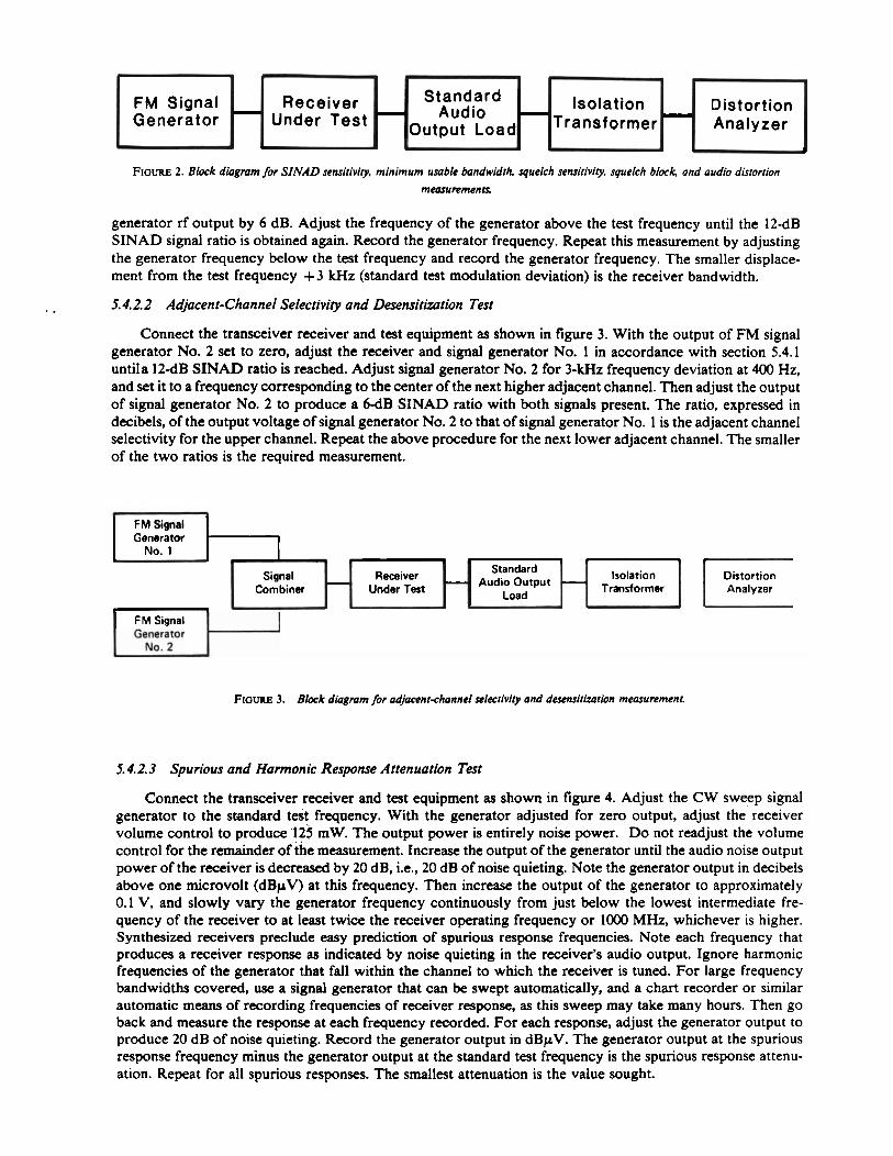
FIGURE 2. Block diagmm for SINAD sensitiviry, minimum usable bandwidrh, squelch sensitivity, squelch bid and audio distortion
measurements
FM Signal Generator
generator rf output by 6 dB. Adjust the frequency of the generator above the test frequency until the 12-dB SlNAn civnnl ratin i~ n h t a i n ~ d avain R w n r d the P ~ n ~ r n t n r f r p n i i e n ~ v Reneat thic rneacttrernent hv ~Airtctina - - - . - - - * ---------- ------. - - - - - - - -- - - ---------- -.-r-..- ".a" -.--..a W..."... Y, YU,..'.... b
the generator frequency below the test frequency and record the generator frequency. The smaller displace- ment from the test frequency + 3 kHz (standard test modulation deviation) is the receiver bandwidth.
.. 5.4.2.2 Adjacent-Channel Selectivity and Desensithtion Test
-
Connect the transceiver receiver and test equipment as shown in figure 3. With the output of FM signal generator No. 2 set to zero, adjust the receiver and signal generator No. 1 in accordance with section 5.4.1 untila 12-dB SINAD ratio is reached. Adjust signal generator No. 2 for 3-kHz frequency deviation at 400 Hz,
A
Receiver Under Test
Standard Audio
-Output Load
and set it to a frequency corresponding to the center i f the next higher adjacent c h i n e l . Then adjust the output -c-:---i .-- mT- ? r- ----I ..-a L A D C T X T A ~ -... :- ... :.I I-AL -:--I- m- A :- UI a1g11a1 ~ C I I C I ~ L U I IIU. L LO ~ I V U U G C P VVD 3111-u ~ a i l ~ WILII WLII S I ~ I I W ~ prcsenL. I ne rariu, eapresseu In
decibels, of the output voltage of signal generator No. 2 to that of signal generator No. 1 is the adjacent channel selectivity for the upper channel. Repeat the above procedure for the next lower adjacent channel. The smaller of the two ratios is the required measurement.
-
FM Signal Generator
No. 1
Standard Audio Output
Isolation T . s r . 4 r . r m r
I F M Signal I
Isolation ~ransformer
3
Distortion - Analyzer ..
Distortion Analyzer
ene era tor No. 2
5.4.2.3 Spurious and Harmonic Response Attenuation Test
J
Connect the transceiver receiver and test equipment as shown in figure 4. Adjust the CW sweep signal generator to the standard test frequency. With the generator adjusted for zero output, adjust the receiver volume control to produce 125 mW. The output power is entirely noise power. D o not readjust the volume control for the remainder of the measurement. Increase the output of the generator until the audio noise output power of the receiver is decreased by 20 dB, i.e., 20 dB of noise quieting. Note the generator output in decibels above one microvolt (dBpV) at this frequency. Then increase the output of the generator to approximately 0.1 V, and slowly vary the generator frequency continuously from just below the lowest intermediate fre- quency of the receiver to at least twice the receiver operating frequency o r 1000 MHz, whichever is higher. Synthesized receivers preclude easy prediction of spurious response frequencies. Note each frequency that produces a receiver response as indicated by noise quieting in the receiver's audio output. Ignore harmonic frequencies of the generator that fall within the channel to which the receiver is tuned. For large frequency bandwidths covered, use a signal generator that can be swept automatically, and a chart recorder or similar automatic means of recording frequencies of receiver response, as this sweep may take many hours. Then go back and measure the response at each frequency recorded. For each response, adjust the generator output to produce 20 dB of noise quieting. Record the generator output in dBpV. The generator output at the spurious response frequency minus the generator output at the standard test frequency is the spurious response attenu- ation. Repeat for all spurious responses. The smallest attenuation is the value sought.
FIGURE 3. Block diagmm for adjacent-channel selectiviry and desensirizurion measurement.

FIGURE 4. Block diagmm for spurious and harmonic response attenuation memrement.
5.4.2.4 I~termodulation Attenuation Test
Connect the transceiver receiver and test equipment as shown in figure 5. With the output levels of FM signal generator Nos. 2 and 3 set to zero, adjust the receiver and FM signal generator No. 1 in accordance with section 5.4.1 until a 12-dB SINAD ratio is reached. Adjust unmodulated generator No. 2 to the center frequency of the next higher adjacent channel. Adjust generator No. 3 for 3-kHz frequency deviation at 400 Hz, and set it to the center frequency of the second higher adjacent channel, i.e., two channels above the standard test frequency. Then adjust the output levels of generator Nos. 2 and 3 to produce a 6 d B SINAD ratio with all three signals present. Maintain generator Nos. 2 and 3 at equal output voltages throughout the measurement. Adjust slightly the frequency of generator No. 3 to obtain the 6 d B SINAD ratio with the minimum signal levels from generator Nos. 2 and 3. The ratio, in decibels, of the output voltage of generator No. 2 (or 3) to that of generator No. 1 is the intermodulation attenuation for the upper channels. Repeat the above procedure for the lower two adjacent channels, with generator No. 3 set to the lowest channel. The smaller of the two ratios is the value sought.
Isolation Transformer
h
f
CW Sweep Signal
Generator
Standard Audio Output
Load
FIGURE 5. Block dingmm for inremodulation attenuation measurement
t
- f
Receiver Under Test
- -
FM Signal Generator
5.4.3 Squelch Tests
AF Voltmeter or Power Meter
-
No. 1
5.4.3.1 Squelch Sensitivity Tests
2
Connect the transceiver receiver and test equipment as shown in figure 2, with or without the isolation transformer, as necessary. Adjust the receiver and FM signal generator in accordance with section 5.4.1 until a 12-dB SINAD ratio is reached. Set the output level of the generator to zero, and measure the audio noise output power. Slowly adjust the squelch control until the audio noise output power drops abruptly (40 dB or more). Do not adjust the squelch control any further. This is the threshold squelch position. Increase the output level of the signal generator until the measured audio output power is within 10 dB of 500 mW. The signal generator output voltage is the value for the threshold squelch sensitivity. Repeat for changes in standard supply voltage of + 10 percent and - 20 percent.
Repeat the above procedure with the squelch control in the maximum squelch position. The resultant signal generator output voltage is the value for tight squelch sensitivity.
Distortion Analyzer
A
FM Signal Generator
No. 3
Isolation Transformer
Standard Audio Output
Load -
A .
- 4 , 4
Receiver Under Test
- , Signal
Combiner FM Signal
No. 2 -
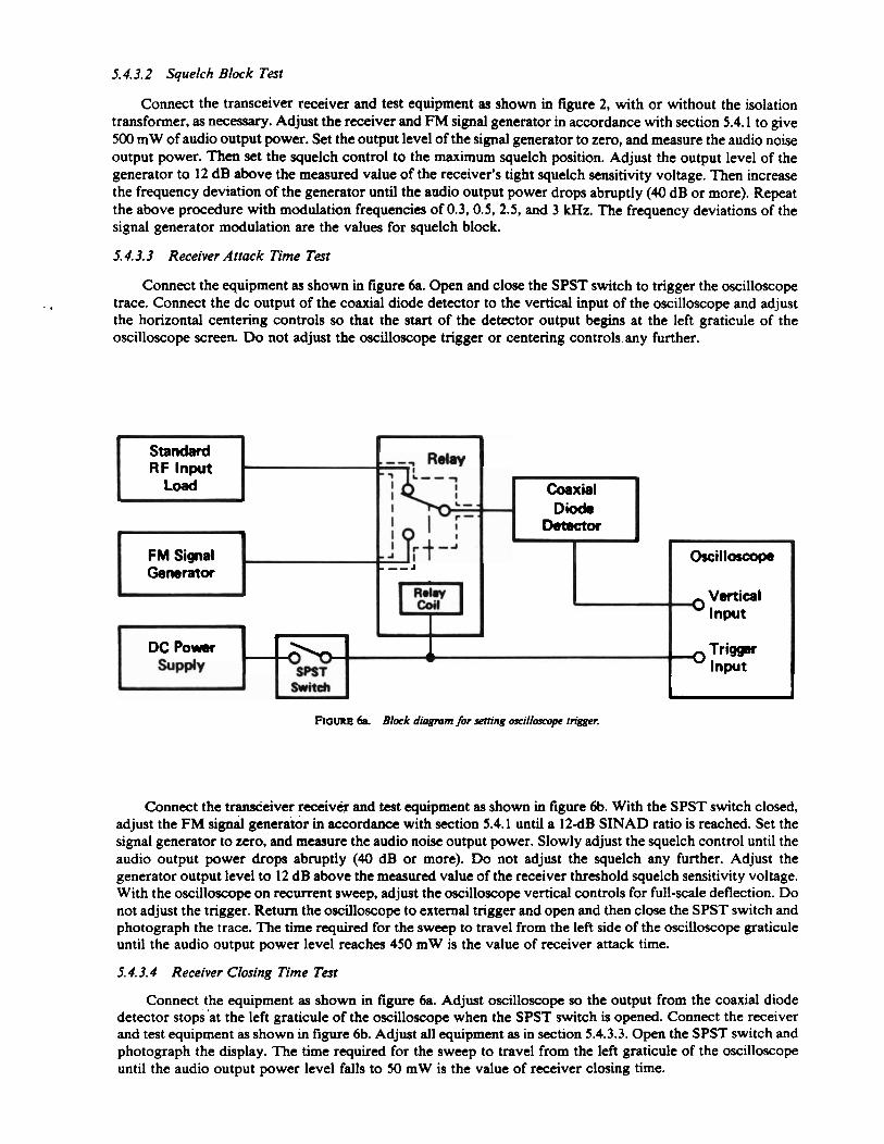
5.4.3.2 Squelch BIock Test
Connect the transceiver receiver and test equipment as shown in figure 2, with or without the isolation transformer, as necessary. Adjust the receiver and FM signal generator in accordance with section 5.4.1 to give 500 mW of audio output power. Set the output level of the signal generator to zero, and measure the audio noise output power. Then set the squelch control to the maximum squelch position. Adjust the output level of the generator to 12 dB above the measured value of the receiver's tight squelch sensitivity voltage. Then increase the frequency deviation of the generator until the audio output power drops abruptly (40 dB or more). Repeat the above procedure with modulation frequencies of 0.3,0.5, 2.5, and 3 kHz. The frequency deviations of the signal generator modulation are the values for squelch block.
5.4.3.3 Receiver Attack Time Test
Connect the equipment as shown in figure 6a. Open and close the SPST switch to trigger the oscilloscope - . trace. Connect the dc output of the coaxial diode detector to the vertical input of the oscilloscope and adjust
the horizontal centering controls so that the start of the detector output begins at the left graticule of the oscilloscope screen. Do not adjust the oscilloscope trigger or centering controls any further.
ROW 6a. Blork diagmrn for setting w c i I I ~ trigger.
Standard RF Input
Connect the transceiver receiver and test equipment as shown in figwe 6b. With the SPST switch closed, adjust the FM signal generator in accordance with section 5.4.1 until a 12dB SINAD ratio is reached. Set the signal generator to zero, and measwe the audio noise output power. Slowly adjust the squelch control until the audio output power drops abruptly (40 dB or more). Do not adjust the squelch any further. Adjust the generator output level to 12 dB above the measwed value of the receiver threshold squelch sensitivity voltage. With the oscilloscope on recurrent sweep, adjust the oscilloscope vertical controls for full-scale deflection. Do not adjust the trigger. Return the oscilloscope to external trigger and open and then close the SPST switch and photograph the trace. The time required for the sweep to travel from the left side of the oscilloscope graticule until the audio output power level reaches 450 mW is the value of receiver attack time.
Load
+
5.4.3.4 Receiver CIosing Time Test
Connect the equipment as shown in figwe 6a. Adjust oscilloscope so the output from the coaxial diode detector stops'at the left graticule of the oscilloscope when the SPST switch is opened. Connect the receiver and test equipment as shown in figure 6b. Adjust all equipment as in section 5.4.3.3. Open the SPST switch and photograph the display. The time required for the sweep to travel from the left graticule of the oscilloscope until the audio output power level falls to 50 mW is the value of receiver closing time.
Coaxial Diods
Detector h b
FM Signal Generator
A
DC Power ~ P P ~ Y
i
Oscilloscope
Vertical 3 Input
T r i m - u

. - FIGURE 6b. Block di4gmm for receiver attack time and receiver closing time measuremena
2
Standard RF lnput
Load
5.4.4 Audio Tests
5.4.4.1 Audio Output Power Test
I
Connect the transceiver receiver and test equipment as shown in figure 7. Modulate the FM signal generator with standard audio test modulation and set it to the standard test frequency. With the signal generator adjusted for 1-mV output, set the receiver volume control to the maximum position and measure the audio output power. Repeat for changes in standard supply voltage of + 10 percent and -20 percent.
Receiver Under Test
FIGURE 7 . Block diagmm for audrb outpur power, audio rsponse, and audio hum and noise measurements
A F Voltmeter or
Power Meter
5.4.4.2 Audio Dirtortion Test
FM Signal Generator .
Connect the transceiver receiver and test equipment as shown in figure 2, with or without the isolation transformer, as necessary. Modulate the FM signal generator with standard audio test modulation and set it to the standard test frequency. With the signal generator adjusted for 1-mV output, adjust the receiver volume control for an audio output power of 500 mW and measure the audio.distortion. Repeat at an audio output power of 3-12 mW for tho* transceivers used with earphones.
F M Signal
Generator
-
5.4.4.3 Audio Response Test
- Standard
-
Connect the transceiver receiver and test equipment as shown in figure 7. Modulate the FM signal generator with standard audio test modulation and set it to the standard test frequency. With the signal generator adjusted for 1-mV output, adjust the receiver volume control for an audio output power of 500 mW. Do not readjust the volume control for the remainder of the measurement. Reduce the generator frequency deviation to 1 kHz, and measure the audio output power. Repeat for modulating frequencies of 0.3.0.5, 2, and 3 kHz. Compute the ratio, in decibels, of each of these latter power levels relative to the output power at I-kHz modulation. Repeat at an output power of 3-12 mW for those transceivers used with earphones.
- Standard
Audio Output Load
i
Receiver Under Test
5.4.4.4 Audio Hum and Noise Tests
I I C
Connect the transceiver receiver and test equipment as shown in figure 7. Modulate the FM signal generator with standard audio test modulation and set it to the standard test frequency. With the signal generator adjusted for I-mV output, adjust the receiver volume control for an audio output power of 500 mW.
Audio Output Load
A F Voltmeter or
Power Meter
- Isolation Vertical Transformer Input
DC Power supply
- - t J
Isolation Transformer
&
- 0 b SPST
Switch
1 Trigger - Input

Do not readjust the volume control for the remainder of the measurement. Remove the modulation from the signal generator and measure the audio hum and noise output power. Compute the ratio, in decibels, of the audio output power to the audio hum and noise output power. This is the value for audio hum and noise (unsquelched).
Set the squelch control to its maximum squelch position. Set the output level of the generator to zero and measure the audio hum and noise output power. Calculate the ratio in decibels of the audio output power to the audio hum and noise output power. This is the value for audio hum and noise (squelched).
5.5 Transmitter Tests
5.5.1 Radio Frequency Canier Tests
5.5. I. I Output Power Test
. Operate the transceiver transmitter without modulation. Measure the output power as shown in figure 8, using standard supply voltage and a power meter accurate to 5 percent. Change the standard supply voltage + 10 percent, allow it to stabilize at least 5 s, and determine the output power. Repeat for changes in standard supply voltage of - 10 percent and -20 percent.
FIGURE 8. Block diagmm for output power measurement.
b
Variabb Power Supply
5.5.1.2 Frequency Stability Test
Operate the transceiver transmitter without modulation. Measure the frequency as shown in figure 9, using standard supply voltage. Change the standard supply voltage + 15 percent, allow it to stabilize for 5 s, and determine the change in frequency. Repeat for a change in standard supply voltage of - 15 percent.
FIGURE 9. Block diagmm for frequency stabilify measuremenr
I
L d
Power W *
FREQUENCY COUNTER
5.5.1.3 AM Hum and Noise Level Test Connect the transceiver transmitter and test equipment as shown in figure 10. Use a linear peak-carrier
responsive AM detector to detect the sampled output of the transmitter. With the transmitter operating at nominal output power with no modulation, measure the dc voltage across the detector load resistor with the
SmKtafd Output Load
Transmitter Under Test
V A R I A B L E POWER
S U P P L Y
n S T A N D A R D
O U T P U T L O A D
. 9 I
T.RANSM1 T T E R UNDER T E S T
S A M P L E R .

high impedance dc voltmeter. Without adjusting the transmitter, measure the peak ac voltage with the oscilloscope. Calculate the AM hum and noise level as 20 loglo (Vflk), where V, is the peak ac voltage and V, is the dc voltage.
d STANDARD
INPUT LOAD r
L I I
T R A N S M I T T E R STANDARD UNDER SAMPLER O U T P U T T E S T LOAD
h o ~ l l ~ 10. Black d&gmm fir AM hum and noisc measurement.
5.5.1.4 Carner Attack Time Test Although carrier attack time is defined in terms of rated carrier output power, the test method described
herein uses a voltage measurement technique to determine the value of this characteristic. Make the mea- surement using a calibrated oscilloscope and peak detector connected as shown in figure l l. The peak detector should have a short time constant (< 10 ms) and provide a linear response with amplitude. Close the trigger circuit of the oscilloscope through the transmitter control switch to start the time interval. The peak detector, sampling the rf carrier, provides a voltage to the oscilloscope vertical input. Measure the time required for the trace to reach 71 percent of the peak detector maximum output.
T R I G G E R V E R T I C A L I N P U T
From 1 1 . BIoek dhgmm fw camer attack time measurement
I T R A N S M I T T E R
U N D E R T E S T
1 1 1
-
S A M P L E R
; I
, S T A N D A R D
O U T P U T L O A D

5.5.2 Audio Modulation Tests
5.5.2.1 Harmonic Distortion Test
Connect the transceiver transmitter and test equipment as shown in figure 12. Operate the transmitter at nominal carrier output power and adjust the audio input for standard audio test modulation. Ensure that the 1-kHz modulating signal has a total distortion of 0.5 percent or less. Process the sampled transmitter output using the test receiver. Connect the distortion analyzer across the standard audio output load to remove the 1-kHz tone and measure the remaining signal, which is a combination of all the noise and harmonic components.
V A R I A B L E A T T E N U A T O R
FlouRe 12. Block diagmm for harmonic distortion and FM hum and noise measurements
I
S A M P L E R A U D I O G E N E R A T O R
-
1 '
5.5.2.2 FM Hum and Noise l ewl '~ ty t . .. .
T R A N S M I T T E R 7 7 U N DE R
T E S T w
L
S T A N D A R D O U T P U T
L O A D I d
A
Connect the transceiver'transmitter and test equipment as shown in figure 12. Operate the transmitter at nominal camer output power and adjust the audio input for standard audio test modulation. Measure the audio output voltage, V, , of the test receiver using the distortion analyzer as a voltmeter. Remove the modulation by disconnecting the audio generator and replacing it with the standard audio input load. Measure the resulting audio voltage, V2 , at the distortion analyzer. Calculate the FM hum and noise level as 20 loglo (Vl/V2). The method provides reliable measurements up to 50 dB.
5.5.2.3 Audio Response Test
I
Connect the transceiver transmitter and test equipment as shown in figure 13, using a broadband matching network (sec. 4.2) to match the audio generator output impedance to the transmitter audio input impedance.
Apply selected audio frequencies from 0.3 to 3 kHz to the transmitter, and maintain the audio input level at a constant 30 percent of rated system deviation (i.e., 1.5 kHz) as observed with the deviation meter. Determine the audio voltmeter reading in decibels relative to the voltmeter reading at 1 kHz for each test frequency, and draw a graph similar to that shown in figure 1.
D I S T O R T I O N T E S T t A N A L Y Z E R R E C E I V E R
S T A N D A R D A U D I O
O U T P U T L O A D
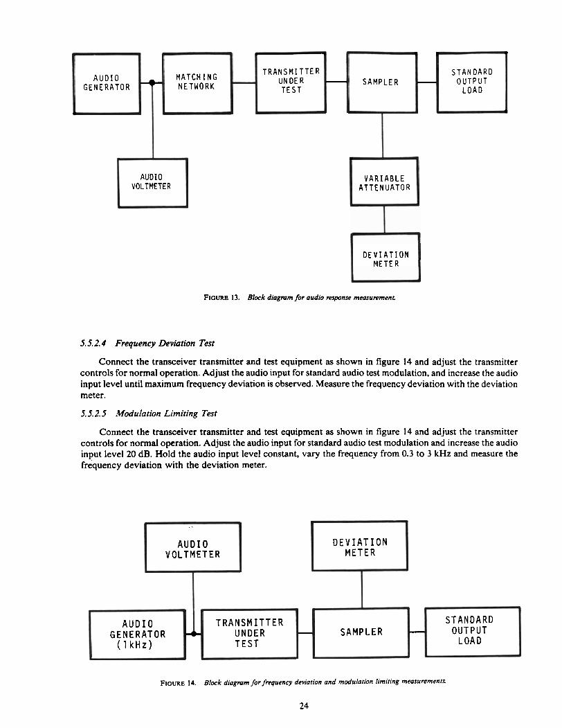
FIGURE 13. Block diognmr for audio response mwruremenl.
L L I
MATCH I N G T R A N S M I T T E R
NETWORK UN DE R - T E S T
5.5.2.4 Frequency Deviation Test
Connect the transceiver transmitter and test equipment as shown in figure 14 and adjust the transmitter controls for normal operation. Adjust the audio input for standard audio test modulation, and increase the audio input level until maximum frequency deviation is observed. Measure the frequency deviation with the deviation meter.
5.5.2.5 Modulation Limiting Test
_L
S T A N D A R D O U T P U T
L O A D
P
S A M P L E R
AUDIO VOLTMETER
i
Connect the transceiver transmitter and test equipment as shown in figure 14 and adjust the transmitter controls for normal operation. Adjust the audio input for standard audio test modulation and increase the audio input level 20 dB. Hold the audio input level constant, vary the frequency from 0.3 to 3 kHz and measure the frequency deviation with the deviation meter.
-
. V A R I A B L E
A T T E N U A T O R
D E V I A T I O N V O L T M E T E R
D E V I A T I O N M E T E R
FIGURE 14. Block diagmm for frequency deviation and modulation limiting measurements.
24
A U D I O
B
S T A N D A R D T R A N S M I T T E R O U T P U T
L O A D J
4
- U N D E R T E S T
G E N E R A T O R ( 1 k H z )
+ S A M P L E R -

5.5.3 Electromagnetic Compatlbillty Tests
5.5.3.1 Radiated Spurious Emissions Test (Type f and II Transceivers)
Set up the test as shown in figure 15, at a site that meets the requirements of section 5.1.9.1. Have a person stand facing the receiving dipole antenna holding the transceiver with the antenna attached 15 cm (6 in) from the body, with the base of the antenna 1.7 m (68 in) above the earth. Place the vertical receiving dipole antenna 30 m (98.4 ft) from the transceiver and 3.0 m (9.8 ft) above the earth. Turn on the transmitter and measure the field strength of the unmodulated carrier frequency in decibels above 1 microvolt per meter (dBpV/m) using the technique described in the following paragraph. Then measure the field strength in dBpV/m of any radiated spurious emissions, from the lowest radio frequency generated in the transmitter to the tenth harmonic of the carrier, or to 1000 MHz, whichever is lower. Calibrate the receiving antenna for each frequency measured.
. . For the carrier and each spurious frequency, position the horizontally-polarized receiving antenna a quarter wavelength in any direction to obtain a maximum reading on the field strength meter. Rotate the transmitter to further increase this maximum reading. Repeat this procedure of raising and lowering the receiving antenna and rotating the transmitter until the largest signal has been obtained and recorded. Then orient the receiving antenna for vertical polarization and repeat the procedure for each spurious signal.
The attenuation of each radiated spurious emission is the field strength in dBpV/m of the carrier frequency minus the maximum field strength in dBpV/m of the radiated spurious emission.
Receiving antenna
FIGURE 15. Block diagmm for mdiated spurious emivion and radiation eflciency measurnmenu for type I and II tmnsceiverr
Personal
5.5.3.2 Radiated Spurious E ~ M & Q Test (Type III and IV ~ransceivers)
transceiver -r- 3 m
Set up the test as shown'in figure 16, at a site that meets the requirements of section 5.1.9.2. Place the microwave absorber, at least 1.8 m (6 ft) wide, on the ground between the mobile transceiver and the receiving
t antenna, as shown. A horn antenna may be used as the receiving antenna, and this test may be performed in an anechoic chamber (sec. 5.2.18). Have a person stand facing the receiving antenna holding the transceiver with the antenna attached 15 cm (6 in) from the body, with the base of the antenna 1.7 m (68 in) above the earth. Place the vertical receiving antenna 3 m (9.8 ft) from the transceiver and 1.7 m (68 in) above the earth. Turn on the transmitter and measure the field strength of the unmodulated carrier frequency in dBpV/m using the technique described in the following paragraph. Then measure the field strength in dBpV/m of any radiated spurious emissions, from the lowest radio frequency generated in the transmitter to 3 GHz. Calibrate the receiving antenna for each frequency measured.
For the carrier and each spurious frequency, rotate the transmitter with the receiving antenna horizontally polarized to obtain a maximum reading on the field strength meter. Record this reading. Then orient the receiving antenna for vertical polarization and repeat the procedure for each spurious signal.
The attenuation of each radiated spurious emission is the field strength in dBpV/m of the carrier frequency minus the maximum field strength in dBpV/m of the radiated spurious emission.
Field
h
strength meter
I Y I
Microwave absorber 1.7 m f
Field strength
9 meter .
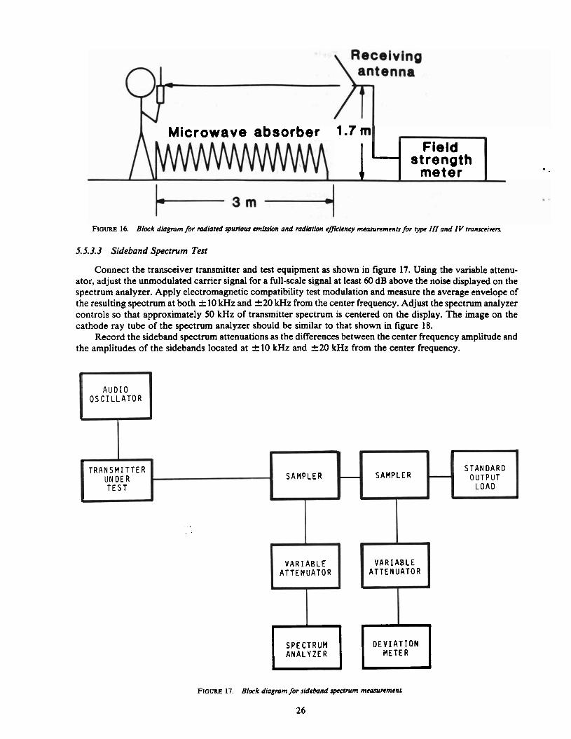
FIGURE 16. Block diagram for mdiated spurious emission and mdiation eficiency mwunments for type III and I V tmnsceiwrs
5.5.3.3 Sideband Spectrum Test
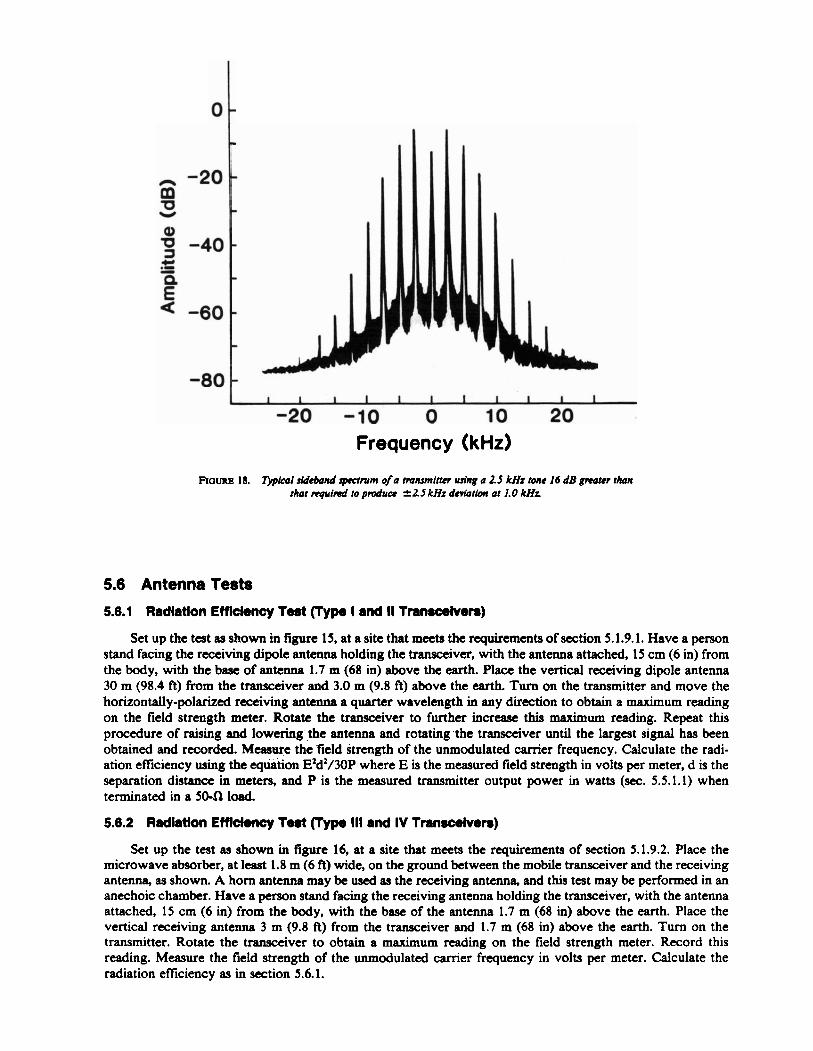
Connect the transceiver transmitter and test equipment as shown in figure 17. Using the variable attenu- ator, adjust the unmodulated carrier signal for a full-scale signal at least 60 dB above the noise displayed on the spectrum analyzer. Apply electromagnetic compatibility test modulation and measure the average envelope of the resulting spectrum at both k 10 kHz and f 20 kHz from the center frequency. Adjust the spectrum analyzer controls so that approximately 50 kHz of transmitter spectrum is centered on the display. The image on the cathode ray tube of the spectrum analyzer should be similar to that shown in figure 18.
Record the sideband spectrum attenuations as the differences between the center frequency amplitude and the amplitudes of the sidebands located at & 10 kHz and r t20 kHz from the center frequency.
FIGURE 17. Block dicrgmm for sideband spectrum meancrcment.
26
A U D I O O S C I L L A T O R
;
b
T R A N S M I T T E R U N D E R T E S T
- - S A M P L E R S T A N D A R D
O U T P U T L O A D
V A R I A B L E A T T E N U A T O R
S A M P L E R
V A R I A B L E A T T E N U A T O R
L
D E V I A T I O N ( :.:::::: I I M E T E R I
I I I I I I 1 I I I I I
-20 -10 0 10 20 Frequency (kHz)
FIGURE 18. 5 p k I sidhnd spumm of a tmnsmifter wing a 2.5 kHz tone I6 dB grroter than that requid to pmdum k2.S kHz &viation at 1.0 kHz
5.6 Antenna Tests
5.6.1 Radlatlon Efficiency Test (Type I and II Tmmcehren)
Set up the test as shown in figure 15, at a site that meets the requirements of section 5.1.9.1. Have a person stand facing the receiving dipole antenna holding the transceiver, with the antenna attached, 15 cm (6 in) from the body, with the base of antenna 1.7 m (68 in) above the earth. Place the vertical receiving dipole antenna 30 m (98.4 ft) from the transceiver and 3.0 m (9.8 ft) above the earth. Turn on the transmitter and move the horizontally-polarized receiving antenna a quarter wavelength in any direction to obtain a maximum reading on the field strength meter. Rotate the transceiver to further increase this maximum reading. Repeat this procedure of raising and lowering the antenna and rotating the transceiver until the largest signal has been obtained and recorded. Measure the field strength of the unmodulated carrier frequency. Calculate the radi- ation eficiency using the equation E2d2/30P where E is the measured field strength in volts per meter, d is the separation distance in meters, and P is the measured transmitter output power in watts (sec. 5.5.1.1) when terminated in a 50-Q load.
5.6.2 Radlatlon EfMemy Toat (Type Ill and IV Tmnacelven)
Set up the test as shown in figure 16, at a site that meets the requirements of section 5.1.9.2. Place the microwave absorber, at least 1.8 m (6 ft) wide, on the ground between the mobile transceiver and the receiving antenna, as shown. A horn antenna may be used as the receiving antenna, and this test may be performed in an anechoic chamber. Have a person stand facing the receiving antenna holding the transceiver, with the antenna attached, 15 cm (6 in) from the body, with the base of the antenna 1.7 m (68 in) above the earth. Place the vertical receiving antenna 3 m (9.8 ft) from the transceiver and 1.7 m (68 in) above the earth. Turn on the transmitter. Rotate the transceiver to obtain a maximum reading on the field strength meter. Record this reading. Measure the field strength of the unmodulated carrier frequency in volts per meter. Calculate the radiation efficiency as in section 5.6.1.

5.7 Battery Service Life Test
Connect the transceiver and test equipment as shown in figure 19. Adjust the transceiver for 500-mW audio output power. Use the signal generator to provide a 1-mV signal to the transceiver receiver. Start the test, and use an interval timer to operate the transceiver in accordance with the battery test duty cycle (5.1.8). Measure the time required for the transmitter output power to decrease by 3 dB.
C O A X I A L RELAY
STANDBY
I m J
S I GNAL . STANDARD
GENE RATOR OUTPUT
LOAD
I
I POWER L I I ADAPTER I : I F R E Q U I R E D '
I N T E R V A L T I M E R
FOR SWITCHIN
PUSH-TO-TALK CONTROL I B A T T E R Y I
FIF 19. Block diagmm for battery service liJi mnuuremenr
[l] Greene, F. M. Technical terms and definitions used with law enforcement communications equipment. LESP-RPT-0203.00. National Institute of Justice, U.S. Dept. of Justice, Washington, DC 2053 1; 1973 July.
121 Private land mobile radio services. Rules and Regulations, Vol. 5, Part 90. Federal Communications Commission, 1919 M Street, NW., Washington, DC 20554.
APPENDIX B-BIBLIOGRAPHY
Batteries for personal/portable transceivers. NILECJ-STD-0211.00. National Institute of Justice, U.S. Dept. of Justice, Washington, D C 20531; 1974 June.
Greene, F. M. NBS field-strength standards and measurements (30 Hz to 100 MHz). Proceedings IEEE 55 (6): 970-981. Institute of Electrical and Electronics Engineers, Inc., 345 East 47th St., New York, NY; 1967 June.
Jesch, R. L.; Berry, I. S. Comparison and performance characteristics for batteries used with law enforcement communications equipment. LESP-RPT-0201.00. National Institute of Justice, U.S. Dept. of Justice, Washington, DC; 1972 May.
Minimum standards for communication antennas, Part 11-Vehicular antennas. EIA Standard RS-329-1. Elec- '- tronic Industries Association, 2001 Eye St., NW., Washington, D C 20006; 1972 August.
Minimum standards for land mobile communication FM or PM receivers, 25-947 MHz. EIA Standard . . RS-204-C. Electronic Industries Association, 2001 Eye St., NW., Washington, D C 20006; 1982 January.
Minimum standards for land mobile communication FM or PM transmitters, 25-470 MHz. EIA Standard RS-152-B. Electronic Industries Association, 2001 Eye St., NW., Washington, D C 20006; 1970 February.
Minimum standards for portable/personal radio transmitters, receivers and transmitter/receiver combina- tion land mobile communications FM or PM equipment, 25-1000 MHz. EIA Standard RS-316-B. Electronic Industries Association, 2001 Eye St., NW., Washington, DC 20006; 1979 May.
Mobile stations FM or PM radiotelephone transceivers operating in certain VHFAJHF'bands in the fre- quency range 27.23 MHz to 470 MHz with R F power output rating not exceeding 10 watts. Canada Dept. of Communications Standard RSS 121; 1971 April 15.
Personal FM transceivers. NILECJ-STD-0209.00. National Institute of Justice, U.S. Dept. of Justice, Washington, D C 2053 1; 1978 December.
Runyon, S. Focus on signal generators and synthesizers. Electronic Design 21 (10); 1973 May 10. Scott, W. W., Jr. Chargers and charging techniques for batteries used with law enforcement communications
equipment. LESP-RPT-0202.00. National Institute of Justice, U.S. Dept. of Justice, Washington, DC 2053 1; 1973 June.
Society of Automotive Engineers, Inc. Capacitor, 10 MFD for EM1 measurements. Aerospace Recommended Practice, ARP 936; 1968 May 3 1.
Specification for aero-space nickel-cadmium storage cells. S-761-P6. Goddard Space Flight Center, Green- belt, MD; 1971 March.
Specification for dry cells and batteries. ANSI C 18.1-1969. American National Standards Institute, 1430 Broadway, New York, NY 10018; 1970.
Taggart, H. E. Field strength calibration techniques at the National Bureau of Standards. IEEE Trans. Electromagnetic Compatibility. EMC-7, No. 2. Institute of Electrical and Electronics Engineers, Inc., 345 East 47th St., New York, NY; 1965 June.
Taggart, H. E. Methods of suppressing automotive interference. Natl. Bur. Stand (U.S.) Spec. Publ. 480-44; 198 1 November.
Taggart, H. E.; Workman, J. L. Calibration principles and procedures for field strength meters (30 Hz to 1 GHz). Natl; Burai..Stand. - ( ~ . ~ . j . ~ e c h . Note 370; 1969 March.
Test procedure for antennas.'IEEE Standard No. 149. Institute of Electrical and Electronics Engineers, Inc., 345 East 47th St., New York, NY; 1965 January.
White, D. R. J. A handbook on electrical noise and electromagnetic interference specifications, Vol. 1. Don White Consultants, Gainsville, VA; 197 1.
9 0 . 5 . G o v e r n m e n t P r i n t ~ n g O f f i c e : 1985 -JQl-i18/4668S 30