Permeable Reactive Barrier Decision Analysis
24
Document ID: EDF-ER-273 Revision ID: 2 Effective Date: 05/14/02 Engineering Design File Permeable Reactive Barrier Decision Analysis Form 412.14 07/24/2001 Rev. 03 Idaho National Enalnewlnn \/ and Envlronmental Laboratory
Transcript of Permeable Reactive Barrier Decision Analysis

Document ID: EDF-ER-273 Revision ID: 2 Effective Date: 05/14/02
Engineering Design File
Permeable Reactive Barrier Decision Analysis
Form 412.14 07/24/2001 Rev. 03
Idaho National Enalnewlnn \/ and Envlronmental Laboratory

431.02 06/2012001 Rev. 09
ENGINEERING DESIGN FILE EDF- ER-273 Rev.No. 2
Page 1 of 2
. Title: Permeable Reactive Barrier Decision Analysis
. Project File No.: NA
. Site Area and Building No.: NA 14. SSC Identification/Equipment Tag No.: NA Summary: This Permeable Reactive Barrier Decision Analysis Study is based on the results of the Hydrologic Modeling of the Final Cover, Liner, and the Fate and Transport Modeling Results and Summary Report.
The studies performed in support of the INEEL CERCLA Disposal Facility (ICDF) Title I Design indicate that a permeable reactive barrier is not effective in protecting human health and the environment from long-lived mobile radiological contaminants leaching from the ICDF. At most, a permeable reactive barrier would minimally slow migration of these contaminants, but would not immobilize them. Proposed permeable reactive barrier materials that have the capability of reducing mobility of 1-1 29 are peat and activated carbon. The life expectancy of these reactive materials is not expected to meet the 1,000-year design life of the facility because of their capacity to react with a large variety of chemicals in addition to the contaminants of concern.
Modeling has demonstrated that an infiltration-reducing cover is more protective of the SRPA. Such an infiltration reduction cover that takes advantage of the local climatic conditions is included as part of the design and will be installed with appropriate layers to protect the soil cover portion of the cover from erosion for 1,000 years or longer.
This Permeable Reactive Barrier Decision Analysis concludes that the use of an infiltration-reducing cover design will be more effective than the use of a permeable reactive barrier in protecting the Snake River Plain Aquifer from migration of landfill contaminants for the design life of the ICDF landfill. The use of a permeable reactive barrier will not increase protection of human health or the environment.
j. Review (R) and Approval (A) and Acceptance (Ac) Signatures:
3. Records Management Uniform File Code (UFC): Disposition Authority: I Retention Period: EDF pertains to NRC licensed facility or INEEL SNF program?: 0 Yes 0 No

431.02 06l20l2001 Rev. 09
ENGINEERING DESIGN FILE EDF- ER-273 Rev. No. 0
Page 2 of 2
9. Registered Professional Engineer’s Stamp (if required)
ABSTRACT
This Design Permeable Reactive Bamer Decision Analysis Study is based on the results of the Leachate Contarpinant Reduction Time Study, Hydrologic Modeling of the Final Cover, Linerhachate Compatibility Study, and the Fate and Transport Modeling Results.
The studies performed in support of the INEEL CERCLA Disposal Facility Title I Design indicated that a permeable reactive barrier is not effective in protecting human health and the environment from long-lived mobile radiological contaminants leaching from the INEEL CERCLA Disposal Facility. Of the materials available for a permeable reactive barrier, none effectively immobilize the migration of contaminants, although some minimally retard migration. Proposed permeable reactive barrier materials that have the capability of reducing mobility of 1-129 are peat and activated carbon, but the life expectancy of these reactive materials is not expected to meet the 1,000-year design life of the facility, because of their capacity to react with a large variety of chemicals in addition to the contaminants of concern.
Modeling has demonstrated that an infiltration-reducing cover that takes advantage of the local climatic conditions is more protective of the Snake River Plain aquifer. Such an infiltration reduction cover is included as part of the design and will be installed with appropriate layers to protect the soil cover portion of the cover from erosion for 1,000 years or longer. As a component of the INEEL CERCLA Disposal Facility design, the low-infiltration cover will be more reliable than an experimental permeable reactive barrier.
This Permeable Reactive Barrier Decision Analysis concludes that the use of an infiltration-reducing cover design will be more effective than the use of a permeable reactive barrier in protecting the Snake River Plain Aquifer from migration of landfill contaminants for the design life of the INEEL CERCLA Disposal Facility landfill. The use of a permeable reactive barrier will not increase protection of human health or the environment.
... 111

iv

CONTENTS ...
ABSTRACT ................................................................................................................................................ 111
ACRONYMS .............................................................................................................................................. vi1 ..
1 . INTRODUCTION ........................................................................................................................... 1-1
1.1 Goals ..................................................................................................................................... 1-1
1.2 Approach ............................................................................................................................... 1-1
2 . INPUTS TO THE PRB DECISION ANALYSIS ........................................................................... 2-1
3 . RESULTS ....................................................................................................................................... 3-1
3.1
3.2
3.3
3.4
3.5
Modeling of Low-Infiltration Cover ..................................................................................... 3-1
3.1.1 Method and Inputs ...................................................................................................... 3-1 3.1.2 Results and Conclusions ............................................................................................. 3-2
Fate and Transport Modeling Results ................................................................................... 3 4
Leachate Contaminant Reduction Time Study ..................................................................... 3-7
Permeable Reactive Barriers ................................................................................................. 3-8
Integration of Results ............................................................................................................ 3-9
4 . CONCLUSIONS AND RECOMMENDATIONS .......................................................................... 4-1
4.1 Conclusions ........................................................................................................................... 4-1
4.2 Recommendations ................................................................................................................. 4-1
5 . REFERENCES ................................................................................................................................ 5-1
6 . BIBLIOGRAPHY ........................................................................................................................... 6-1
V

vi
CERCLA
COC
DOE
DOE-ID
EDF
HI
HWMA
ICDF
INEEL
MCL
NOAA
ou PCB
PRB
RCRA
RDX
RAO
ROD
scs SRPA
TSCA
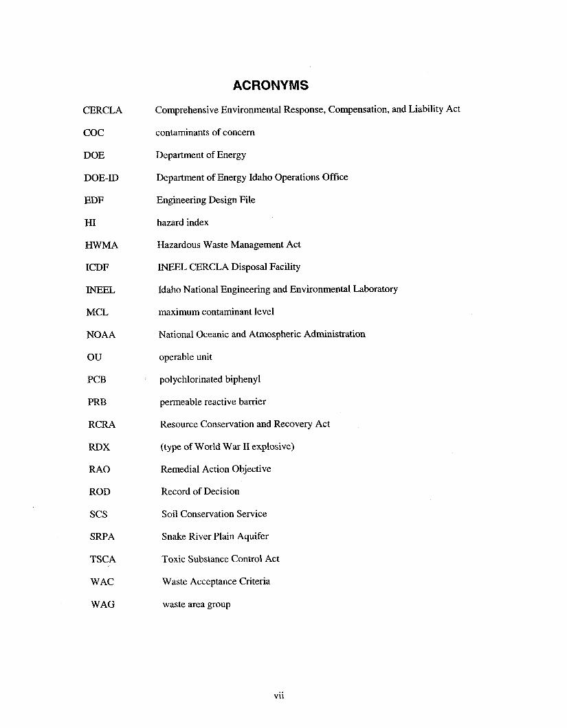
ACRONYMS
Comprehensive Environmental Response, Compensation, and Liability Act
contaminants of concern
Department of Energy
Department of Energy Idaho Operations Office
Engineering Design File
hazard index
Hazardous Waste Management Act
INEEL CERCLA Disposal Facility
Idaho National Engineering and Environmental Laboratory
maximum contaminant level
National Oceanic and Atmospheric Administration
operable unit
polychlorinated biphenyl
permeable reactive barrier
Resource Conservation and Recovery Act
(type of World War I1 explosive)
Remedial Action Objective
Record of Decision
Soil Conservation Service
Snake River Plain Aquifer
Toxic Substance Control Act
WAC Waste Acceptance Criteria
WAG waste area group
vii

Permeable Reactive Barrier Decision Analysis
1. INTRODUCTION
The Idaho National Engineering and Environmental Laboratory (INEEL) has selected consolidation of low-level mixed radioactive waste into a central landfill, the INEEL CERCLA Disposal Facility (ICDF) landfill, as the remedial action for Waste Area Group (WAG) 3 Operable Unit (OU) 3-13 Group 3 surface soils. The OU 3-13 Record of Decision (ROD) (DOE-ID 1999) authorizes the design and construction of the ICDF landfill for consolidation of WAG 3 and INEEL-wide Comprehensive Environmental Response, Compensation, and Liability Act (CERCLA) remediation wastes. Design and construction of the ICDF Complex will be compliant with the requirements of Department of Energy (DOE) Order 435.1, Resource Conservation and Recovery Act (RCRA) Subtitle C, Idaho Hazardous Waste Management Act (HWMA), and Toxic Substance Control Act (TSCA) polychlorinated biphenyl (PCB) landfill design and construction requirements.
This permeable reactive barrier (PRB) Decision Analysis Study was performed to determine the need for and effectiveness of a PRB as part of the ICDF landfill liner system to protect the Snake River Plain aquifer (SRPA) from migration of highly mobile contaminants placed in the ICDF landfill.
1.1 Goals
The goal of the PRB Decision Analysis Study is to determine whether a PRB is necessary to prevent the release of leachate from the ICDF to the underlying aquifer, which would result in the following:
A cumulative carcinogenic risk exceeding 1 in 10,000 (1 x from the aquifer
due to ingestion of groundwater
0 A total Hazard Index (HI) of 1 due to the ingestion of groundwater from the aquifer
0 An exceedance of applicable State of Idaho groundwater quality standards (Le., maximum contaminant levels [MCLs]) in the aquifer.
1.2 Approach
This PRB Decision Analysis Study summarizes and integrates results from the following Department of Energy Idaho Operations Office (DOE-ID) Engineering Design Files (EDFs) and reports:
0 “Leachate/Contamination Reduction Time Study”(EDF-ER-274)
0 “Fate and Transport Modeling Results” (EDF-ER-275)
0 “Hydrologic Modeling of Final Cover” (EDF-ER-279)
0 “Liner and Final Cover Long-Term Performance Evaluation and Final Cover Life Cycle Expectation” (EDF-ER-28 1)
0 “INEEL CERCLA Disposal Facility Design Inventory” (EDF-ER-264)
1-1

Review of Reactive Materials to Support the Design of an ICDF Attenuation Barrier, Waste Area Group 3, Operable Unit 3-13, at the Idaho National Engineering and Environmental Laboratory (DOE-ID 2000).
Each of the above documents was reviewed and results of all of the studies were then integrated to make the final determination of the need for a PRB.
1-2

2. INPUTS TO THE PRB DECISION ANALYSIS
The amount of contaminants to be disposed in the ICDF landfill was taken from the “INEEL CERCLA Disposal Facility Design Inventory,” (EDF-ER-264). This inventory is a conservative approximation of the contaminant mass expected to be disposed in the landfill. A combination of chemical and physical factors was included in the decision analysis. Chemical factors include the chemistry of the expected waste and contaminant types (radionuclide, inorganic, and organic contamination). Chemical contaminant migration factors were evaluated in the Review of Reactive Materials to Support the Design of an ICDF Attenuation Barrier, Waste Area Group 3, Operable Unit 3- 13, at the Idaho National Engineering and Environmental Laboratory (DOE-ID 2000).
Physical factors include both engineered and natural systems. The hydrologic properties of the engineered ICDF landfill system include components that are designed and installed to minimize moisture migration both into and out of the landfill. These components are the low-infiltration cap, clay liners, leachate collection system, and flexible membrane liners. Hydrologic properties of the waste itself are also included in the studies. Physical factors of the natural system components are included in the fate and transport modeling studies. The natural system components are the amount of precipitation that was considered in the hydrologic modeling of the final cover and the hydrologic properties of the vadose zone, including basalt, and associated sedimentary interbeds that were considered in the fate and transport modeling.
Contaminant-specific migration factors included in the evaluation were the partitioning coefficient (Kd) and decay.
2- 1

3. RESULTS
The following sections summarize the results of the “Fate and Transport Modeling Results,” (EDF-ER-275), the “Hydrologic Modeling of Final Cover,” (EDF-ER-279), and the Review of Reactive Materials to Support the Design of an ICDF Attenuation Barrier, Waste Area Group 3, Operable Unit 3- 13, at the ldaho National Engineering and Environmental Laboratory (DOE-ID 2000).
3.1 Modeling of Low-Infiltration Cover
The methods and results of the cover modeling are described below.
3.1.1 Method and Inputs
The Title I “Hydrologic Modeling of Final Cover” EDF showed that the upper and middle cover sections of the ICDF cover with a flat surface alone were effective in reducing the infiltration using conservative estimates of long-term base and extreme cases of climatological conditions to less than 0.4 and 0.5 mm average annual infiltration, respectively (EDF-ER-279). Since the cover will be sloped, infiltration will be further reduced due to surface water run-off. Moreover, drainage from the upper and middle sections will be intercepted by the lower section barriers and diverted through the lateral drainage layer.
To determine percolation at the base of the ICDF cover, the hydrologic model was expanded to include the lower section of the cover and the two-dimensional (e.g., vertical and lateral) drainage paths. An evaluation was also made to determine the increase in infiltration due to cover defects (e.g., burrowing animals and silt migration clogging drain layers). Additionally, a sensitivity analysis was performed to optimize the water storage layer thickness and provide an upper bound of precipitation.
Methods used for hydrologic modeling of the final cover included the combination of an unsaturated flow model for determining the upper cover section infiltration and analytical solutions for determining surface water run-off, lateral drainage, and infiltration due to cover defects. One-dimensional flow through the upper section was determined through the use of the unsaturated hydrologic model SoilCover 2000, Version 5, developed by the University of Saskatchewan (Geo-Analysis 2000). Surface water run-off from the sloped cover surface was determined using the curve number developed by the U.S. Soil Conservation Service (SCS) (Soil Conservation Service 1972). Lateral drainage was determined with the use of Dupuit unconfined groundwater flow equations (Fetter 1994).
The ICDF landfill waste will be capped with a robust state-of-the practice cover to minimize long- term infiltration. The cover system will minimize infiltration through several mechanisms, including promoting surface water run-off, water storage and release to the atmosphere, and lateral drainage, in addition to a low permeability compacted clay barrier layer with a flexible membrane liner. The cover can be divided by function into three main sections. Each section and its function are listed below:
Upper section: The upper water storage component provides water storage during wet periods for later release into the atmosphere during dry periods
0 Middle section: The biointrusion provides protection from burrowing animals and a capillary break
Lower section: The lower section meets RCRA Subtitle C requirements and provides a barrier and drainage layer to promote lateral drainage.
3-1

The cover design includes a sloped surface to promote surface run-off and lateral drainage. Each component in the cover profile is shown on Figure 3-1.
COARSE SAND
COARSE SAND
Figure 3-1. Schematic of modeled cover section.
The capillary break was designed to inhibit drainage through the soil under unsaturated conditions and increase the consumptive use of water by evapotranspiration. Lateral drainage layers are incorporated in the design to remove water in the event breakthrough would occur from the upper cover section. The material properties used in the simulations are representative of materials that may be found near the site and will be used during construction of the ICDF cover. The actual hydraulic properties of the materials used during construction will be tested and included in the model at a later date.
3.1.2 Results and Conclusions
The Title I “Hydrologic Modeling of Final Cover” EDF showed that the upper and middle cover sections alone for a flat surface were effective in reducing the infiltration using conservative estimates of long-term base and extreme cases of climatological conditions to less than 0.4 and 0.5 mm average annual infiltration, respectively (EDF-ER-279). The results of current hydrologic model show that infiltration is further reduced, by surface run-off and lateral drainage, to less than 0.1 mm per year at the base of the cover system. Cover defects due to borrowing animals and potential drainage layer clogging was shown to increase infiltration by 0.01 mm per year.
Used for the analysis was an extreme climatic scenario consisting of a 10-year period, with an average climatic condition and an annual precipitation, followed by four years with precipitation above the 90th percentile value. The weather data were provided by the INEEL and covered the years 1950 through 1994. Weather data for 1995 was supplied by the National Oceanic and Atmospheric Administration (NOM) from data collected at the LNEEL site.
3-2

The silt loam water storage layer thickness was varied from 0.25 to 3.5 m to determine the optimum water storage layer thickness. The results of the sensitivity analysis indicate that the water storage layer provides the maximum reduction in infiltration at a minimum thickness of 2 m. Increasing the water storage layer thickness may provide additional protection for erosion and other aeolian effects; however, additional thickness will not further reduce infiltration.
The effect of increased precipitation on infiltration through the water storage layer of the cover was analyzed by using an average year of weather and repeating that weather scenario until water movement in the soil profile reached a quasi-steady state. The one-dimensional computer model SoilCover 2000 was used to simulate one, two, three, and four times the 1975 precipitation. Twenty years were modeled for each precipitation interval using two 10-year simulations to determine the quasi-steady state. Based on the analysis, the upper cover section remains effective to three times the average annual precipitation of 8 10 &year.
The results of the extreme case simulation indicate 0.1 mm/yr of percolation through the lower section of the soil cover into the waste. This is considered reasonably conservative for the reasons listed below:
0 All snow was assumed to melt in a 22day period, stressing the cover’s water storage capacity.
0 The water storage capacity of the cover is 3.3’times the average annual precipitation amount.
The unsaturated permeability of the silt-loam, fine sand, and coarse sand was not allowed to go below 1 x (essentially, not allowing the cover to reach a very dry condition).
centimeters per second (cds) , providing a conservative residual moisture
0 A poor stand of grass was assumed to simulate drought or post-fire conditions.
0 The analysis does not include the benefit of a flexible membrane liner barrier in the cover’s lower section.
0 The daily precipitation was distributed over 12 hours, allowing more water to infiltrate into the cover.
0 The years selected for the weather data included large precipitation events early on in the simulation to stress the recovery capacity of the cover.
An extreme case was modeled that assumed the 10-year base case was followed by four years of back-to-back precipitation events that were above the 90th percentile based on the period of record.
0 Bio-intrusion does not account for increased evaporation from lower depths of the soil resulting from increased air circulation or for evaporation and dispersion resulting from precipitation moving through the soil.
The sensitivity results show that the cover will perform as modeled for precipitation up to three times the annual average. Increasing the water storage layer thickness greater than 2-m results in minimal improvement in hydraulic performance.
The results presented for infiltration through the ICDF cover are consistent with results from other studies of comparable cover systems under similar climatic conditions. Previous studies have been conducted to evaluate the moisture movement in engineered barriers at the INEEL (Magnuson 1993). One
3-3

of the barriers evaluated by Magnuson included a 1.5-m soil cover over a gravel (0.15 m) and cobble (0.76 m) capillary break. This cover design is similar to that proposed for the ICDF, in that it was designed as a store and release cover over a capillary break. Simulations indicated that drainage through the upper soil layer for this cover was extremely low, on the order of the mass balance error of the simulations (Magnuson 1993). Drainage through the soil layer was believed to be associated with drainage of the initial moisture in the profile.
Based on the results from the simulations reported in this EDF for the ICDF cover, results from experimental studies at the INEEL, and experimental and modeling results from other sites in the western United States, it is believed that the cover design proposed for the ICDF represents a state-of-the-practice design for a landfill cover that minimizes infiltration into the waste. Any leakage that occurs through the cover is likely to be intercepted by the lateral drainage layers at the base of the cover. A conservative estimate of 0.1 &year of percolation from the base of the cover was determined based on the estimated breakthrough from the upper section of the cover. Based on the results reported in this EDF, the cover design, which incorporates a store and release soil cover underlain by a capillary break, is believed to represent the best technology for minimizing infiltration into the landfill, given site-specific climatic conditions.
3.2 Fate and Transport Modeling Results
The contaminant fate and transport modeling effort has shown that the naturally arid environment of the INEEL, in combination with the evaporation and storage cover design, can effectively prevent contaminants from exceeding the remedial action objectives (RAOs) for groundwater at a nearby down- gradient compliance point. The fate and transport modeling, conducted to develop dilutiodattenuation factors for site contaminants, used a two-dimensional numerical model to simulate the migration of contaminants from the waste soil placed in the landfill, through the vadose zone, and into the underlying Snake River Plain Aquifer. Based on the results of the hydrologic modeling of the final landfill cover design, a recharge rate of 0.0001 d y r was selected as the maximum design recharge rate for the contaminant fate and transport and ultimate assessment of downgradient compliance with groundwater RAOs. Dilutiodattenuation factors were derived from the modeling effort to calculate peak amval times for contaminants with similar transport characteristics (i.e., similar partition coefficients). The concentration of contaminants expected to be present in groundwater at the time of peak concentration was calculated with the use of literature values for environmental half-lives of contaminants and the elapsed time to the peak concentration arrival derived from the dilutiodattenuation factors and transport simulation.
The simulations were compared to the design basis waste inventory for the ICDF landfill to identify constituents that have potential to exceed the groundwater RAOs. At the maximum design recharge rate (0.ooOOl d y r ) , all of the radionuclides in the design inventory met the groundwater RAOs of not exceeding maximum contaminant levels, excess cancer risk of 1.0E-4, or a hazard index equal to, or greater than, 1 for toxic non-carcinogens. In addition, for all radionuclides with peak concentrations arriving within the same time periods, cumulative risk was less than the risk-based FUOs. The results of simulated transport of selected radionuclides of interest are presented in Table 1.
3-4

Table 1. Results of contaminant transport simulations for radionuclides at maximum design recharge rate of O.OOO1 d y r scaled to ICDF inventory.
Compliance Point Peak Concentration - decayed (pCi/L)
Hazard Index = 1 Cumulative Excess 1 x lo4 Modeled Risk-based Risk-based Cancer Risk for Time
Contaminant Result MCL Concentration Concentration Period of Peak Arrival
H-3 2.63E - 07 2.00E - 04 6.04E + 03 NA 3.85E - 06 1-129 8.68E - 01 1.00E + 00 2.67E + 00 NA 3.85E - 06 TC-99 2.02E + 00 9.00E + 02 5.56E + 01 NA 3.85E - 06 U-235 2.45E - 03 1.50E + 01 9.41E - 02 NA 3.85E - 06 Np-237 8.19E - 03 1.50E + 01 5.38E - 02 NA 3.85E - 06 Sr-90 0.00E + 00 8.00E + 00 6.51E + 00 NA 5.75E - 07 Zn-65 0.00E + 00 3.00E + 02 5.10E + 01 NA 5.75E - 07 EU-155 O.00E + 00 6.00E + 02 6.27E + 0 1 NA 5.75E - 07 CS- 137 OBOE + 00 2.00E t. 02 2.44E - 05 NA 5.75E - 07 CO-60 0.OOE + 00 1 .00E + 02 2.28E + 01 NA 5.75E - 07 U-238 4.35E - 02 1.50E + 01 1.02E - 01 NA 5.75E - 07
The approach applied to the radionuclides was also used for organic compounds and nonradioactive inorganic constituents in the waste. Decayed concentrations at the time of peak groundwater concentration were calculated for all constituents in the design basis inventory. The results indicated that some constituents might approach the groundwater RAOs if placed in the landfill at the design inventory concentrations without treatment.
Table 2 presents a list of non-radioactive constituents for which the simulated compliance point concentrations based on the design inventory were greater than 10% of the applicable groundwater RAOs. It is important to note that simulated concentration of several of these constituents approached RAOs because literature research produced no values for either partition coefficients (&) or for environmental half lives (for example, Nitroanilines). In the absence of either of these factors, the transport simulation assumes un-retarded and un-decayed transport, which, in some cases, produces unrealistically high compliance point concentrations. The constituents that are subject to this uncertainty and apparent over- estimation of compliance point concentration include numerous petroleum hydrocarbon compounds that are logically expected to degrade under ambient environmental conditions. Table 3 lists design inventory constituents for which no transport, decay, or toxicity data have been identified.
3-5

Table 2. Results of contaminant transport simulations for selected non-radioactive constituents at maximum design recharge rate of 0.0001 d y r scaled to ICDF inventory.
Compliance Point Peak Concentration - decayed (mg/L)
Risk Group Risk Group Hazard Cumulative Cumulative Excess
Index = 1 Risk- Hazard Index Cancer Risk for Modeled Risk-based based for Time Period Time Period of
Contaminant Result MCL Concentration Concentration of Peak Arrival Peak Arrival Fluoride 3.11E-3 4.00E + 00 NA 1.63E - 02 1.79E - 02 3.85E - 06
RDX” 0.00E00 NA 1.4E - 03 1.35E - 04 1.79E - 02 3.85E - 06
3.85E - 06 Cyanide 2.71E - 04 2.00E - 01 NA 4.62E - 05 1.79E - 02
2-Nitroaniline 2.19E - 05 NA NA 2.58E - 06 1.79E - 02 3.85E - 06
3-Nitroaniline 2.19E - 05 NA NA 2.58E - 06 1.79E - 02 3.85E - 06
3.85E - 06 4-Nitroaniline 2.19E - 05 NA NA 2.58E - 06
Boron 7.8E-04 NA NA 3.07E - 04 1.79E - 02 3.85E - 06
Molybdenum 1.79E - 04 NA NA 1.36E - 03 3.23E - 02 5.75E - 07
Barium 2.37E - 04 2.00E + 00 NA 7.76E - 06 3.23E - 02 5.75 E - 07
1.79E - 02
NA = Not Applicable. a. = No design inventory has been identified for RDX (type of World War 11 explosive).
Table 3. Summary of design inventory constituents for which no transport, decay, or toxicity data were identified in Tier 1 analysis.
Chemical Name Nature of Compound Potential Surrogates 3-Methyl Butanal Flavoring compound Not determined
3P-Dimethyl Decane Not Determined Not determined
Dimethyl Disulfide Not Determined Not determined
Eicosane Straight chain hydrocarbon used in cosmetics, lubricants, plastics
Not determined
Ethyl cyanide Solvent, chemical intermediate Not determined
2,6,10,15-Tetra Heptadecane
2,3,7-Trimethyl Octane
Not Determined
Not Determined
Not determined
Not determined
o-Toluenesulfonamide Plasticizer Not determined
p-Toluenesulfonamide Plasticizer Not determined
Tributylphosphate Metal extractant Not determined
4,6-Dimethyl Undecane Not determined Not determined
In addition, site-specific background concentrations for some elemental constituents ( e g , fluoride, barium, and boron) have not been determined and the concentrations reported in the design basis
3-6
inventory may be within normal background levels. Elemental constituents present at background levels would not be subject to disposal limitations on-Site.
Waste Acceptance Criteria (WAC) will be established to ensure that RAOs for these constituents are not exceeded. WACS are established on the assumption that no PRB is present.
The fate and transport modeling supports the decision to not include a permeable reactive barrier for the following reasons:
0 Most of the constituents, including all of the radionuclides, expected to be present in waste soil disposed to the landfill will not exceed RAOs for groundwater concentrations at the compliance point. Therefore, a PRB would provide no additional benefit to human health and the environment.
0 The few constituents that have a potential to exceed the groundwater RAOs at the compliance point can be readily managed by either treatment or administrative controls (i.e., Waste Acceptance Criteria) to prevent exceedence of the RAOs.
3.3 Leachate Contaminant Reduction Time Study
The “Leachate/Contaminant Reduction Time Study,” (EDF-ER-274) simulated concentrations of selected design inventory constituents in ICDF landfill leachate over the 15-year operations period. The purpose of the study was to examine the change in leachate concentration and the corresponding change in the waste over time. Two groups of screened design inventory constituents were evaluated in the leachatekontaminant reduction time study. One group was screened on the basis of partition coefficients and the other on the basis of concentration in the design inventory. The latter group was entered into a geochemical model to simulate solubility constraints on the resulting leachate concentrations.
Concentrations of each group were entered into a spreadsheet program that simulated partitioning to the solid phase via adsorption, radioactive decay, and leachate removal from the landfill. The leachate will be a brackish water dominated by sodium and sulfate and buffered by carbonates to a pH of around 8.2. The results indicate less than 1% of the inventory masses of the most mobile constituents (iodine and technetium) would be removed from the landfill during the operation period with an infiltration rate of 1 cdyear.
Estimated water recharge through the landfill waste mass was the only input parameter that was varied. Simulations were performed using 1.0 cm and 10.0 cm annual recharge. The estimated volume of landfill leachate generated annually is approximately 550,000 L at the 1.0 cm recharge rate, and 5,500,000 L at the 10 cm per year recharge rate. Under the landfill leaching scenario developed for the geochemical simulation, an annual recharge rate of approximately 0.3 m/yr would be required to remove 90% of the design inventory masses of 1-129, Tc-99, and Np-237 from the waste during the operations period.
The “Leachate Contaminant Reduction Time Study,” (EDF-ER-274) indicates that more than 90% of the design inventory mass of the most mobile contaminants, 1-129, Tc-99, and Np-237, will be in the ICDF landfill at closure. This inventory is considered to be essentially equal to the design inventory for the purposes of the PRB decision analysis. (This decrease in source term was not included in the Tier 1 Fate and Transport Study.)
The study assumes that all waste is placed in the landfill at time zero, that the waste is completely saturated, and that all contaminants are in solution at saturation or, for constituents selected on the basis
3-7

of I(d only, that there are no solubility constraints on the leachate solution. All of these conservative assumptions are meant to maximize the calculated concentrations of contaminants in the leachate.
3.4 Permeable Reactive Barriers
Permeable reactive barriers are a recent and promising remedial technology for minimizing the transport of contaminants carried in groundwater. A PRB is designed to allow contaminated water to flow through its permeable, but reactive material, which sorbs, precipitates, destroys, or converts the contaminants to a less harmful chemical form. Reactive barriers may consist of both reactive and structural material placed in situ in a trench, cutoff wall, or grout curtain. Reactive barriers are generally applied to saturated groundwater systems. However, they have also been applied to a limited extent in landfill liners, as at the DOE Weldon Spring Site. The most common use for PRBs is in situ means of remediating groundwater contamination. Numerous reactive materials have been investigated, but zero- valent iron is the most commonly used inorganic material (Garaskar et al. 1998).
A literature review of reactive materials was performed for DOE-ID (DOE-ID 2000) specifically addressing contaminants of concern (COCs) 1-129, N-237, and Tc-99. The authors concluded that several of the materials reviewed (most notably peat and activated carbon) retarded one or more of the above COCs, and none of the materials barriers reviewed immobilized all three of the COCs. Other sources of general information on PRBs are Garaskar et al. (1998), EPA (1998), and Morrison and Spangler (1993).
The literature review evaluated the use of metallic iodate salts to control solubility of 1-129. Salts of mercury (HgI,) and silver (AgI,) were shown to have sufficient insolubility to be potentially useful as solubility controls on iodine transport. However, the toxicity of these metals disqualifies them from further consideration as part of a permeable reactive barrier.
Controlling iodine sorption as a mechanism to retard iodine was evaluated by Gu and Schultz (1991). In their review of soils literature, they found that most soils and many soil minerals do not have the properties to effectively sorb iodide. They found that soils high in aluminum-rich clays, allophane, and imgogoite (andisols) could have the properties to sorb iodide. The literature review found that the materials most suitable to sorb iodide were peat, activated carbon, and andisols(D0E-ID 2000).
Andosols (soils of volcanic origin) are found in a variety of locations throughout the “ring of fire” (Le., the volcanic areas surrounding the Pacific Ocean). These soils have been extensively studied in Japan, where they comprise an important portion of the agricultural production areas of the country. These soils have been long known to exhibit substantial sorption capacity for anions (including oxyanions of phosphorous, iodine, bromine, and nitrogen). The exact mechanism of this observed sorption has not yet been identified. The soils that exhibit this effect are generally welldeveloped surface soils with high organic content. Numerous studies suggest that these soils may not be good candidates for incorporation into a landfill liner. The soils tend to lose their anion sorption capacity when autoclaved, suggesting a biological component. Other studies indicated maximum sorption of iodine at moderate moisture content (i.e., about 50% saturation), slightly acid pH (Le., about 5.0), and cool temperatures (i.e., about 15°C). The ion sorption mechanism appears to be a complex action of the soil system as a whole and the dramatic physical changes imposed on a soil compacted into a landfill liner would appear to likely negate the sorptive effects of the soil. Furthermore, little or no information is available regarding the structural properties of these soils with respect to expected settlement (Kouichi Yuita et al. 1991).
The literature review suggested a combination of inventory evaluation and geochemical modeling as a first step in determining which material to evaluate further (DOE-ID 2000). Following the modeling, batch and column studies would be required, followed by larger scale laboratory tests. A PRB would require a phased lab-scale treatability study approach followed by a long-term field trial to determine if
3-8

the PRB would act as designed in reducing the migration speed of 1-129. The authors noted that the longevity of several of the materials with the most promising ability to retard the COCs, such as activated carbon and peat, was a potential problem. On the basis of the literature review, the PRB would retard, and not immobilize 1-129. This long-lived radionuclide would eventually reach the aquifer under the natural recharge conditions of the site without some type of low infiltration barrier or inventory control.
3.5 Integration of Results
The leachate, fate and transport, and final cover studies discussed above were performed independently of each other. Integration of the results provides a conceptual model of how the system will work and shows how results of one study may influence another. Integration also provides an examination of how conservative assumptions in the separate studies combine to establish whether a PRB is necessary. The conservative elements of the individual studies are discussed below.
0 The leachate contaminant reduction study was conservative in making assumptions that maximize leaching of contaminants from the waste. The Tier 1 Fate and Transport Modeling did not include leaching of contaminants that would reduce the source term.
The SoilCover modeling was conservative in the surface runoff assumptions for both climate scenarios modeled by forcing infiltration of precipitation. Modeling the extreme climate scenario was conservative for a landfill that is designed to last 1,000 years. Additionally, no functionality of the drainage boundary underlying the storage/evapotranspiration cover was included.
Fate and transport modeling assumed that all contaminants were in solution at the beginning of the modeling with no solubility restrictions.
The fate and transport modeling assumed O.OOO1 d y r infiltration into the waste. When lateral drainage at the capillary barrier is taken into account, no infiltration into the waste occurs.
3-9

4. CONCLUSIONS AND RECOMMENDATIONS
4.1 Conclusions
The goal of the PRB Decision Analysis Study was to determine whether a PRB is necessary to meet the RAOs. The conclusions from integrating the three independent studies include the following:
1.
2.
3.
4.
5 .
6.
7.
There are no reactive barrier materials that will react effectively with 1-129.
The result of modeling with a cap for 1 ,OOO years meets all criteria during the life of the cap.
Hydrologic modeling with an infiltration flux of 0.01 d y r (approximate natural conditions with no cover system) indicates 1-129 and Np-237 would exceed both the loe4 risk level and the 1 pCi/L 1-129 MCL in the SRPA.
The same modeling, using an infiltration rate achievable with a low-infiltration cover, and not accounting for lateral drainage, indicates that 1-129 would be in the risk level.
If the lateral drainage is accounted for, the infiltration into the waste is essentially zero. For comparison, the infiltration rate of 0.00005 d y r shows that all contaminants are below the level and the MCL for 1-129.
risk
Modeling of inorganic and organic constituents (both carcinogenic and non-carcinogenic) in the Fate And Transport Modeling report indicated an HI > 0.1 for several constituents at the lowest modeled infiltration rate (EDF-ER-275).
Installation of a PRB will not be a value-added approach to controlling 1-129 following the life of the cap because it does not bind 1-129, but only delays its arrival to the SRPA. Currently available materials that would be used in a PRB will not increase protection to human health and the environment for 1-129.
4.2 Recommendations
A combination of low-infiltration cover and inventory control via the ICDF Landfill WAC is recommended for the ICDF to demonstrate that it will meet all groundwater RAOs.
4- I

5. REFERENCES
DOE-ID, 2000, Review of Reactive Materials to Support the Design of an ICDF Attenuation Burner, Waste Area Group 3, Operable Unit 3-13, at the Idaho National Engineering and Environmental Laboratory, DOWID-10791, Rev. 0, Grant Environmental, Inc., A SCENTECH Inc. Company, Idaho Falls, Idaho, November 2000.
DOE-ID, 1999, Final Record of Decision, Idaho Nuclear Technology and Engineering Center, Operable Unit 3-13, DOE/ID-10660, Rev. 0, Department of Energy Idaho Operations Office, Idaho Falls, Idaho, U.S. Environmental Protection Agency Region 10, and State of Idaho Department of Health and Welfare.
EDF-ER-264,200 1, “INEEL CERCLA Disposal Facility Design Inventory,” Rev. A, Environmental Restoration Program, Idaho National Engineering and Environmental Laboratory, March 200 1.
EDF-ER-274,2002, “Leachate/Contamination Reduction Time,” Rev. 1, Environmental Restoration Program, Idaho National Engineering and Environmental Laboratory, May 2002.
EDF-ER-275,2002, “Fate and Transport Modeling Results,” Rev. 2, Envirobental Restoration Program, Idaho National Engineering and Environmental Laboratory, May 2002.
EDF-ER-279,2002, “Hydrologic Modeling of Final Cover,” Rev. 2, Environmental Restoration Program, Idaho National Engineering and Environmental Laboratory, May 2002.
EDF-ER-28 1,2002, “Liner and Final Cover Long-Term Performance Evaluation and Final Cover Life Cycle Expectation,” Rev. 1, Environmental Restoration Program, Idaho National Engineering and Environmental Laboratory, May 2002.
EPA, 1998, Permeable Reactive Barrier Technologies for Contaminant Remediation, EPA/600/R-98/125, Environmental Protection Agency, 94 pp.
Fetter, C.W., 1994, Applied Hydrogeology, Macmillan College Publishing Company, Inc., New York, New York.
Garaskar, A.R., et al., 1998, Permeable Barriers for Groundwater Remediation: Design, Construction, and Monitoring,. Battelle Press, Columbus, OH, 188pp.
Geo-Analysis 2000 Ltd., 2000, “SoilCover User’s Manual,” 202 Kerr Rd., Saskatoon, Saskatchewan, Canada.
Gu, B. and R.K Schulz, 1991, Anion Retention in Soil: Possible Application to Reduce Migration of Buried Technetium and Iodine, A Review, NUREG/CR-5464,33pp.
Kouichi Yuita, et al, 1991, “Dynamics of Iodine, Bromine, and Chlorine in Soil”, Soil Science and Plant Nutrition, Vol. 37 (l), pp. 61-73.
Magnuson, S., 1993, Simulation Study of Moisture Movement in Proposed Barriers for the Subsurface Disposal Area, INEEL, EGG-WM- 10974, Idaho National Engineering Laboratory, EG&G Idaho, Inc., Idaho Falls, Idaho.
5-1
Morrison, S.J. and R.R. Spangler, 1993, “Chemical Barriers for Controlling Groundwater Contamination,” Environmental Progress, Vol. 12, No. 3, pp. 175-181.
Soil Conservation Service, 1972, SCS National Engineering Handbook, Section 4, “Hydrology,” US. Department of Agriculture, Washington, D.C.
5-2

6. BIBLIOGRAPHY
Anderson, Jay, Teresa Ratzlaff, Eric Duffin, and Micha Miller, 1997, Comparison of Four Protective Cap Designs for Burial of Hazardous Waste at the Idaho National Engineering and Environmental Laboratory, Environmental Science and Research Foundation, Annual Technical Report Calendar Year 1996, Environmental Science and Research Foundation, Idaho Falls, Idaho.
Anderson, J.E., R.S. Nowak, T.D. Ratzlaff, and O.D. Markham, 1993, “Managing Soil Moisture on Waste Burial Sites in Arid Regions,” Journal of Environmental Quality, Vol. 22: pp 62-69.
Dwyer, S.F., 2001, “Finding A Better Cover,” Civil Engineering, American Society of Civil Engineers, Reston, VA.
Hakonson, T.E., K.L. Maines, R.W. Warren, K.V. Bostick, G. Trujillo, J.S. Kent, and L.J. Lane, 1994, Hydrologic Evaluation of Four Landfill Designs at Hill Air Force Base, Utah, Report LAUR-93- 4469, Los Alamos National Laboratory, Los Alamos, New Mexico.
Khire, Milind, Craig Benson, and Peter Bosscher, 2000, “Capillary Barriers: Design Variables and Water Balance,” Journal of Geotechnical and Geoenvironmental Engineering, August 2000.
Martian, P., 2000, Screening Model Results of a Mixed Low-Level Waste Disposal Facility Proposed for the ldaho National Engineering and Environmental Laboratory, EDF-ER- 170, INEEL 2000- 00406, Idaho National Engineering and Environmental Laboratory, Idaho Falls, Idaho.
Porro I. and K.N. Keck, 1998, Engineered Barrier Testing at the lNEEL Engineered Barriers Test Facility: FY-1997 and FY-1998, INEELEXT-98-00964, Idaho National Engineering and Environmental Laboratory, RWMC Operations Department, Idaho Falls, Idaho.
PNNL, 2000, Subsurface Transport Over Multiple Phases Description “STOMP” User’s Guide, PNNL- 12034, Pacific Northwest National Laboratory, Richland, Washington,
PNNL, 1996, STOMP-Subsugace Transport Over Multiple Phases, User’s Guide, PNNL - 12034, Pacific Northwest National Laboratory, Richland, Washington, 2000.
Stormont, J.C., 1996, “The Effectiveness of Two Capillary Barriers on a 10% Slope,” Geotechnical and Geological Engineering, Chapman & Hall.
6- 1


![SIDISA 2012 - UniPa · experimental study on the reliability of column tests for the design of permeable reactive barriers [id 1121] - calabro’ p.s. combined use of reactive barrier](https://static.fdocuments.in/doc/165x107/5fc26adbe1405c39a03fd1e4/sidisa-2012-unipa-experimental-study-on-the-reliability-of-column-tests-for-the.jpg)