Permanent Magnet DC Commutator Motor
21
Permanent Magnet DC Commutator Motor The use of permanent magnets (PMs) in construction of electrical machines brings the following benefits: No electrical energy is absorbed by the field excitation system and thus there are no excitation losses which means substantial increase in efficiency, Higher power density and/or torque density than when using electromagnetic excitation, Better dynamic performance than motors with electromagnetic excitation (higher magnetic flux density in the air gap), Simplification of construction and maintenance, Reduction of prices for some types of machines. The use of very poor quality hard magnetic materials (steel or tungsten steel) soon discouraged the use of permanent magnet in favor of electromagnetic excitation systems. The invention of Alnico in 1932 revived PM excitation systems; however, its application was limited to small and fractional horsepower d.c. commutator machines. At the present time most PM d.c. commutator motors with slotted rotors use ferrite magnets. Cost effective and simple d.c. commutator motors with barium or strontium ferrite PMs mounted on the stator will still be used in the foreseeable future in road vehicles, toys, and household equipment. Permanent Magnet DC Motor or PMDC motor (Source: http://electrical4u.com/permanent-magnet-dc-motor-or-pmdc-motor/) In a dc motor , an armature rotates inside a magnetic field . Basic working principle of DC motor is based on the fact that whenever
-
Upload
pavan-kumar -
Category
Documents
-
view
38 -
download
9
description
the brief description about PMDC motors and its applications.
Transcript of Permanent Magnet DC Commutator Motor
Permanent Magnet DC Commutator MotorThe use of permanent magnets (PMs) in construction of electrical machines brings the following benefits:
No electrical energy is absorbed by the field excitation system and thus there are no excitation losses which means substantial increase in efficiency,
Higher power density and/or torque density than when using electromagnetic excitation,
Better dynamic performance than motors with electromagnetic excitation (higher magnetic flux density in the air gap),
Simplification of construction and maintenance, Reduction of prices for some types of machines.
The use of very poor quality hard magnetic materials (steel or tungsten steel) soon discouraged the use of permanent magnet in favor of electromagnetic excitation systems. The invention of Alnico in 1932 revived PM excitation systems; however, its application was limited to small and fractional horsepower d.c. commutator machines. At the present time most PM d.c. commutator motors with slotted rotors use ferrite magnets. Cost effective and simple d.c. commutator motors with barium or strontium ferrite PMs mounted on the stator will still be used in the foreseeable future in road vehicles, toys, and household equipment.
Permanent Magnet DC Motor or PMDC motor (Source: http://electrical4u.com/permanent-magnet-dc-motor-or-pmdc-motor/)
In a dc motor, an armature rotates inside a magnetic field. Basic working principle of DC motor is based on the fact that whenever a current carrying conductor is placed inside amagnetic field, there will be mechanical force experienced by that conductor. All kinds ofDC motors work in this principle only. Hence for constructing a dc motor it is essential to establish a magnetic field. The magnetic field is obviously established by means of magnet. The magnet can by any types i.e. it may be electromagnet or it can be permanent magnet. When permanent magnet is used to create magnetic field in a DC motor, the motor is referred as permanent magnet dc motor or PMDC motor. Have you ever uncovered any battery operated toy, if you did, you had obviously found a batteryoperated motor inside it. This battery operated motor is nothing but a permanent magnet dc

motor or PMDC motor. These types of motor are essentially simple in construction. These motors are commonly used as starter motor in automobiles, windshield wipers, washer, for blowers used in heaters and air conditioners, to raise and lower windows, it also extensively used in toys. As the magnetic field strength of a permanent magnet is fixed it cannot be controlled externally, field control of this type of dc motor cannot be possible. Thus permanent magnet dc motor is used where there is no need of speed control of motor by means of controlling its field. Small fractional and sub fractional kW motors now constructed with permanent magnet.Construction of Permanent Magnet DC Motor or PMDC Motor
As it is indicated in name of permanent magnet dc motor, the field poles of this motor are essentially made of permanent magnet. A PMDC motor mainly consists of two parts. A stator and an armature. Here the stator which is a steel cylinder. The magnets are mounted in the inner periphery of this cylinder. The permanent magnets are mounted in such a way that the N – pole and S – pole of each magnet are alternatively faced towards armature as shown in the figure below. That means, if N – pole of one magnet is faced towards armature then S – pole of very next magnet is faced towards armature.
In addition to holding the magnet on its inner periphery, the steel cylindrical stator also serves as low reluctance return path for the magnetic flux. Although field coil is not required in permanent magnet dc motor but still it is sometimes found that they are used along with permanent magnet. This is because if permanent magnets lose their strength, these lost magnetic strengths can be compensated by field excitation through these field coils. Generally, rare earth hard magnetic materials are used for this permanent magnet.

Rotor: The rotor of pmdc motor is similar to other DC motor. The rotor or armature of permanent magnet dc motor also consists of core, windings and commutator. Armature core is made of number of varnish insulated, slotted circular lamination of steel sheets. By fixing these circular steel sheets one by one, a cylindrical shaped slotted armature core is formed. The varnish insulated laminated steel sheets are used to reduce eddy current loss in armature of permanent magnet dc motor. These slots on the outer periphery of the armature core are used for housing armature conductors in them. The armature conductors are connected in a suitable manner which gives rise to armature winding. The end terminals of the winding are connected to the commutator segments placed on the motor shaft. Like other dc motor, carbon or graphite brushes are placed with spring pressure on the commutator segments to supply current to the armature.
Working Principle of Permanent Magnet DC Motor or PMDC Motor
As we said earlier the working principle of PMDC motor is just similar to the generalworking principle of DC motor. That is when a carrying conductor comes inside a magnetic field, a mechanical force will be experienced by the conductor and the direction of this force is governed by Fleming’s left hand rule. As in a permanent magnet dc motor, the armature is placed inside the magnetic field of permanent magnet; the armature rotates in the direction of the generated force. Here each conductor of the armature experiences the mechanical force F = B.I.L Newton where B is the magnetic field strength in Tesla (weber / m2), I is the current in Ampere flowing through that conductor and L is length of the conductor in metre comes under the magnetic field. Each conductor of the armature experiences a force and the compilation of those forces produces a torque, which tends to rotate the armature.
Equivalent Circuit of Permanent Magnet DC Motor or PMDC Motor
As in PMDC motor the field is produced by permanent magnet, there is no need of drawing field coils in the equivalent circuit of permanent magnet dc motor. The supply voltage to the armature will have armature resistance drop and rest of the

supply voltage is countered by back emf of the motor. Hence voltage equation of the motor is given by,
Where I, is armature current and R is armature resistance of the motor.Eb is the back emf and V is the supply voltage.
Advantages of Permanent Magnet DC Motor or PMDC Motor
PMDC motors have some advantages over other types of dc motors. They are:
No need of field excitation arrangement. No input power in consumed for excitation which improves efficiency of
dc motor. No field coil hence space for field coil is saved which reduces the overall
size of the motor. Cheaper and economical for fractional kW rated applications.
Disadvantages of Permanent Magnet DC Motor or PMDC Motor
In this case, the armature reaction of DC motor cannot be compensated hence the magnetic strength of the field may get weak due to demagnetizing effect armature reaction.
There is also a chance of getting the poles permanently demagnetized (partial) due to excessive armature current during starting, reversal and overloading condition of the motor.
Another major disadvantage of PMDC motor is that, the field in the air gap is fixed and limited and it cannot be controlled externally. Therefore, very efficient speed control of DC motor in this type of motor is difficult.
Applications of Permanent Magnet DC Motor or PMDC Motor
PMDC motor is extensively used where small dc motors are required and also very effective control is not required, such as in automobiles starter, toys, wipers, washers, hot blowers, air conditioners, computer disc drives and in many more.

PMDC Motor(Source: http://www.johnsonelectric.com/en/resources-for-engineers/automotive-applications/motion-technology/pmdc-motor.html)
DC Motors
Basic configuration
Permanent magnet DC brushed motors (PMDC motors) consist of permanent magnets, located in the stator, and windings, located in the rotor.
The ends of the winding coils are connected to commutator segments, that make slipping contact with the stationary brushes. Brushes are connected to DC voltage supply across motor terminals.
Change of direction of rotation can be achieved by reversal of voltage polarity.
The current flow through the coils creates magnetic poles in the rotor, that interact wthe permanent magnet poles. In order to keep the torque generation in same direction, the current flow must be reversed when the rotor north pole passes the stator south pole.
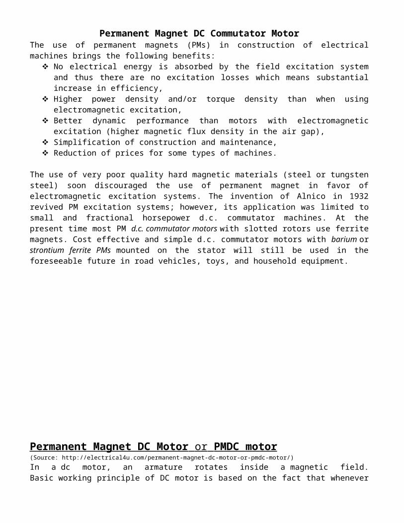
For this the slipping contacts are segmented. This segmented slip ring is called commutator. Left picture shows angular position just before commutation of rotor winding current, right picture after it.
Real DC motors have more than two windings and commutator segments, for generation of a more constant torque.
Picture below shows a 5 segment design (HC685LG).
Permanet magnets are fixed by a spring (NF213G)

This is an exploded view of JE PMDC motor size
Commutator segments are made from copper. This motor above has 3 segments.
Brushes are made from precious metal (metal finger leaf brush) or carbon (graphite brush).
Precious metal brush features:
Used for low voltage, continuous operation. Lower contact resistance and thus voltage drop than graphite brushes.

Less electromagnic noise generation than graphite brushes Designed as "Finger leaf metal brushes" - brush is splitted into several thin fingers,
providing better contact to commutator segments.
Graphite brush features:
Used for high power , high speed, frequent starting, high lifetime, high voltage. Designed as carbon leaf brush or cage brush (for especial high lifetime).
Carbon leaf brushes and Finger leaf metal brushes (right)
Cage brushes:
Brush offset / Direction of rotation
Brushes can be shifted by some small angle in reference to the permanent magnet (brush offset). That can favor one direction of rotation, but the other direction has higher sparkling and worse performance.
The stall torque for the favor rotation will be less, but the max. efficiency point will be higher.
JE has both options, to provide offset and no offset (zero oriented) according to the customer application. Existing JE motor codes are designed for an offset or not, must be checked if to use them for new application.
Permanent magnets
JE offers 3 basic versions of magnets:
Motor code P: Plastics (Rubber) magnet, glued to housing. Motor code H: Dry or wet pressed magnet, segments held by springs or glued.
Stronger than P. Motor code Q: Rare earth magnet, for very high torque and efficiency.

Rotor iron lamination stack
The windings are located in slots, around the rotor silicon steel. For reduction of eddy current losses, the rotor steel is made of sheets, with insulation layer between (lamination stack).
Keeper ring
JE adds a soft iron sheet around the motor housing, for many motors. It reduces the magnetic circuit resistance and improves
performance.
End cap
JE offers two versions of end-cap:
metal (plastics brush holder inserted)o better heat sink for bushing (at high speed)o ball bearing can be pressed ino EMI noise shielded better plasticso lower costso no ball bearing possible
EMI noise suppression
Brushed DC motors generate EMI (ElectroMagnetic Interference) noise, whenever the brushes change from one to another commutator segment.
The higher the supply voltage, speed and current - the higher the noise emission. The emission also depends on number of segments (i.e. voltage drop between neighbouring segments).
The noise is emitted by two ways:
Conduction along power supply wires Radiation through the air
The noise has to be limited according to directives and standards. For that, JE can make tests and implement noise suppression means. Preferably, for these tests the whole customer appliance should be used.
Additional to means such as twisting and shielding of wires, there is a choice of several suppression components:

Varistors
Capacitor
Capacitors
Varistors+Capacitor
Capacitors+Chokes
Capacitor can be inserted inside #300, but not inside #200. 2 Capacitors + 2 chokes can be inserted inside #600 (metal end cap version).
Performance

U = I • R + U
Ui ... voltage induced in windings (back-EMF)
Ui = k • ω (ω … angular speed, ω = 2 • π • n)
Torque generation is: T = k • I
Factor k depends on motor design features (number of winding turns, permanent magnet strength, air gap distance, rotor diamter, rotor length).
It is fixed with the design, but varies due to motor manufacturing tolerances.
There is also an influence of temperature (k gets lower at rising temperature, due to lower magnet strength).
Basic equation of DC motor is:ω = U/k – R/k2 • T
It says that speed is highest at no load condition and decreases with rising load torque.
Losses and Efficiency
No-load losses PO:Friction losses at bearings and at brushes, Hysteresis and Eddy current losses.As these losses must be covered by a no-load torque and hence no-load current – there are also no-load current losses in the winding: IO
2 x R.
Load losses:At rising load torque, the current and thus winding current losses increase.Winding current is maximum when rotor is stalled: Ploss max = U2 / R
At point of max.efficiency there is best ratio Pmech / Pel = Pmech /(U • I).
Efficiency at this point is about η = (1 - √ IO/Istall)2
At point of max.mechanical output power, the speed is half of no-load speed.
Output power Pmech max is little less than U2 / 4 R.
Lifetime
DC motor lifetime is limited by wear of brushes. It depends on
Speed (commutator surface speed) Current load (average current and peaks, start/stop frequency) Brush configuration, brush material (see above) and commutator design
Typical lifetime of JE PMDC motors ranges from 300 hours (small motors) to about 2000 hours (larger motor sizes, cage brushes, continuous operation of rather low output power).

Performance Curve
Manufacturing tolerance
In serial production, the motors have a manufacturing tolerance.Tolerance of no load speed is specified by +-10%, but is lower usually.

Rated operating point
Rated operating point (rated torque) is defined for continuous duty cycle operation, usually.But motor design can be also made for low duty cycle operation or short time operation at rated point, especially for high speed motors.
Rated point is located at point of max.efficiency or between point of max.efficiency and point of max output power.
Lower duty cycle operation allows higher torque load (overload).
Permissible overload is restricted by winding temperature increase.
If the motor carries high current (low voltage, thick wire design) it is also effected by commutator/brushes.
A heat sink (metal flange to metal rack or gearbox) increases loadability.
Performance at increased motor temperature
An increase of motor temperature can be caused by
Self-warming up due to motor losses after some time of operation Higher ambient temperatur
There are two effects:

Permanent magnet strength decreases – causing higher no load speed Winding resistance increases – causing lower stall current.
Both effects reduce stall torque value.
Performance at reduced supply voltage
The speed curve reduces proportional to the voltage. Vice versa, it increases with rising voltage (but to consider reduced lifetime or even thermal overloading of the motor).
This is valid within limits, about +-50% decrease/increase of voltage.
High Voltage DC Motors (HVDC)

HVDC motors can be connected to mains supply voltage level 120 Vac or 230 Vac. JE has special expertise to design motor components accordingly, especially the commutator assembly.
A rectifier is needed to convert AC into DC. It is located inside the motor (if there is space available) or outside.
A changeover switch is to use for bidirectional operation.
HVDC are replacing Universal motors in many applications. Advantage is a reduction of copper material (use of per-manent magnets instead of stator field winding) and less weight.
JE RangeMotor Code
Example: NF183LG(diam 20.4 mm)

Example: QC857SG(diam 49 mm)
Learn MoreEncoders
Encoders (Sensors) can be implemented inside the motor or mounted to motor rearside.
They are needed for a precise speed control or angular position control. Typical application: Printers and scanners.
There are different options:
Optical encoders Hall-effect magnetic sensors Resolvers
JE offers a range of several optical encoders.
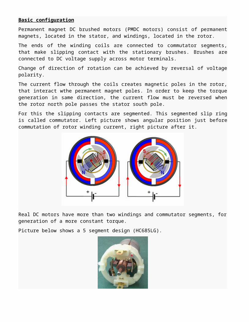
Basic principle is: A slotted wheel or a black/transparent strip photo print is rotating with the motor shaft. A photosensor provides a sinuswave or pulse pattern, that follows the speed of the motor.
Output signal can be analog (0...3.3Vac) or digital (0...3.3 Vdc or 0...5Vdc).One signal or two signals phase shifted 90° (enabling detection of direction of rotation ; allows 4x resolution)
Several options for resolution. Terminology: CPR (Counts Per Revolution) and LPI (Lines Per Inch).
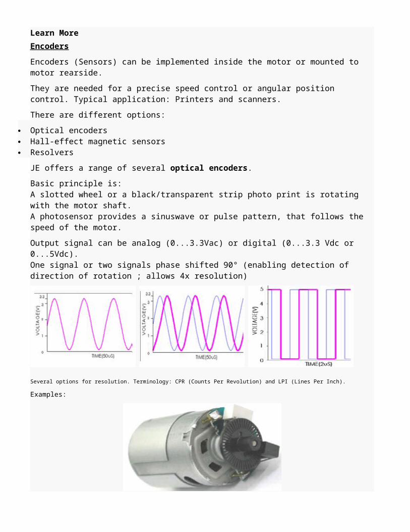
Examples:

HC385MG with slotted encoder wheel(CPR = 48; one signal, sinewave 0...3.3Vac)
NF123G with fotoprint wheel(CPR= 32; two signals, sinewave 0...3.3Vac)
Permanent magnet (PM) DC motors (Source: http://www.ohioelectricmotors.com/permanent-magnet-dc-motors-649)
Permanent magnet (PM) DC motors were introduced in the 19th century but did not earn widespread acceptance due to the poor quality of magnetic materials (e.g., steel and tungsten steel) that were then available. So, early motor designers turned to electromagnetic field excitation, which became the standard until recently. Advances in magnetic technology, such as rare earth magnets, demonstrated improvements in a PM motor’s steady state performance and power density. As a result, the permanent magnet DC motor has seen broad adoption in today’s global
marketplace. PM motors are used by vendors of computer peripherals, office equipment, medical instruments, automobiles, robots and others. BenefitsThe benefits of PM field-excited motors over electromagnetically-excited motors include:
Higher efficiency since no electrical energy is used or losses incurred for developing or maintaining the motor’s magnetic field.
Higher torque and power density. Linear torque speed charcteristics. that are more predictable. Better dynamic performance due to higher magnetic flux density in air gap. Simplified construction and essentially maintenance-free. More compact size.
ConstructionPermanent magnet DC motors are much more efficient, lighter and compact than comparably sized wound DC motors because the permanent magnets replace the field windings of wound DC motors. PM DC motors are constructed in two broad categories: brushed/commutator and brushless. The PM DC commutator motor uses a rotating armature winding with a stationary field of permanent magnets; a PM DC brushless motor has a reverse construction: a rotating field of permanent magnets and a stationary armature winding that is externally commutated by an electronic control. (Sales of permanent magnet DC commutator motors are steadily decreasing while sales of PM DC brushless motors are increasing due to the absence of brushes and the associated maintenance of the brushes and commutator. Subsequent discussion in this article will refer to the PM DC brushless motor.)The field PM magnets have two configurations: surface-mounted or interior-mounted. Surface-mounted magnets are less expensive but are not suited to high speeds. Interior-mounted, also called flux concentrating machines, overcome the shortcoming of surfaced mounted machines in terms of air gap flux density, harmonics shielding and, in some cases, structural integrity.In the 19th century, magnets were made of iron but it was known that alloys of copper, silver and gold made superior magnets. In 1932, Alnico (alloy of AL, CU, Fe NI and Co) was developed and reawakened interest in permanent magnet field excitation. In the past 20 years, other magnetic materials have been developed: rare earth magnets, which are samarium-cobalt alloys and are the highest performing magnetic materials. Rare earth magnets are expensive but their price is decreasing. Another material is neodymium-iron-boron alloy, which performs 30 % better than samarium cobalt alloys. The only drawback of neodymium is its poor corrosion resistance; however, protective coatings have been developed to overcome this deficiency. Ceramic (barium ferrite and strontium ferrite) magnet motors are widely used in the world today. They have much higher coercive forces than alnico and are better able to resist demagnetization. CharacteristicsPermanent magnet DC motors have similar characteristics to DC shunt wound motors in terms of torque, speed, reversing and regenerative braking characteristics. However, PM DC motors have starting torque several times that of shunt motors and their speed load characteristics are more linear and predictable. Torque varies a lot with speed, ranging from maximum (stall torque at zero speed) to zero torque at maximum (no load speed). An increase in torque requires a decrease in angular velocity and vice versa.

MaintenanceReduced maintenance is one of the primary advantages of permanent magnet DC motors over wound DC motors. Since the commutator and brush assemblies of wound motors are not used in PM DC motors, all the maintenance and related-costs associated to servicing these motor components is eliminated. The maintenance amounts to cleaning, ensuring clear ventilation pathways and bearing replacements, as appropriate.ApplicationsPermanent magnet DC motors have been used in power ranges from the milliwatts (mW) to megawatts (MW), but are primarily known for fractional horsepower applications. Brushless DC motors are gaining the most market share. This is the result of advances in control electronics as well as PM quality. The automotive industry uses a large number of PM DC commutator motors, which can vary from a few in an inexpensive car to about 100 in a luxury car. PM brushless DC motors are now recognized as the best propulsion motor for electric hybrid road vehicles. For industrial applications, permanent magnet DC motors are seeing market adoption in applications, such as pumps, fans, blowers, compressors, centrifuges, mills, hoists, handling systems, machine tools, servo drives, elevators, light railways, missiles, radar, satellites, dentist drills, electric wheel chairs, artificial heart motors and power tools.