Perimeter Relief and Control Joints in Fire-Rated Gypsum Board · Perimeter Relief and Control...
15
R. Edwards Code Training 1 | Page November 2, 2016 Perimeter Relief and Control Joints in Fire-Rated Gypsum Board In multi-family residential construction, involving fire-rated assemblies stress relief in the fire- rated assemblies is important, but often overlooked. The 2015 Gypsum Association Fire Resistance Design Manual (the 21 st Edition or GA-600-2015) addresses perimeter relief and control joints in fire rated gypsum panel assemblies in Section II on page 18. It is specifically noted that these control and strain relief designs do not affect the fire rating of any rated assembly. Since the 2009 version or the 20 th edition of the Gypsum Association Fire Resistance Design Manual is a Standard Reference in the 2016 CBC (Chapter 35), this Standard Reference has the same standing as the Code for the 2016 Code Cycle. The 2015 FRDM is not adopted in the 2016 CBC, but why not use the design recommendations in the most current version of this Standard Reference? A number of Strain Relief designs are listed in the 2015 Gypsum Association Fire Resistance Design Manual on pages 279 to 301 and include walls, ceilings, shafts, and head wall conditions. “Control joints in the gypsum panel products shall be specified by the architect or designer where any of the following conditions exist: 1. A control joint shall be installed where a partition, wall, or ceiling traverses a construction joint (expansion, seismic, or building control element) in the base building structure. 2. Control joints shall be installed where a wall or partition runs in an interrupted straight plane exceeding 30 linear feet (9m). 3. Control joints in direct applied interior ceilings and suspended ceilings without perimeter relief, shall be installed so that the linear dimensions between control joints do not exceed 30 ft. (9m). 4. Control joints in suspended ceilings with perimeter relief shall be installed so that the linear dimensions between control joints do not exceed 50 ft. (14m). 5. Control joints in exterior ceilings and soffits shall be installed so that linear dimensions between control joints do not exceed 30 ft. (9m). 6. A control joint or intermediate blocking shall be installed where ceiling framing changes direction. 7. Control joints shall be installed where specified by the architect or designer as a design accent or architectural feature.”
Transcript of Perimeter Relief and Control Joints in Fire-Rated Gypsum Board · Perimeter Relief and Control...
R. Edwards Code Training 1 | P a g e November 2, 2016
Perimeter Relief and Control Joints in Fire-Rated Gypsum Board
In multi-family residential construction, involving fire-rated assemblies stress relief in the fire-rated assemblies is important, but often overlooked. The 2015 Gypsum Association Fire Resistance Design Manual (the 21st Edition or GA-600-2015) addresses perimeter relief and control joints in fire rated gypsum panel assemblies in Section II on page 18. It is specifically noted that these control and strain relief designs do not affect the fire rating of any rated assembly. Since the 2009 version or the 20th edition of the Gypsum Association Fire Resistance Design Manual is a Standard Reference in the 2016 CBC (Chapter 35), this Standard Reference has the same standing as the Code for the 2016 Code Cycle. The 2015 FRDM is not adopted in the 2016 CBC, but why not use the design recommendations in the most current version of this Standard Reference? A number of Strain Relief designs are listed in the 2015 Gypsum Association Fire Resistance Design Manual on pages 279 to 301 and include walls, ceilings, shafts, and head wall conditions. “Control joints in the gypsum panel products shall be specified by the architect or designer where any of the following conditions exist:
1. A control joint shall be installed where a partition, wall, or ceiling traverses a construction joint (expansion, seismic, or building control element) in the base building structure.
2. Control joints shall be installed where a wall or partition runs in an interrupted straight plane exceeding 30 linear feet (9m).
3. Control joints in direct applied interior ceilings and suspended ceilings without perimeter relief, shall be installed so that the linear dimensions between control joints do not exceed 30 ft. (9m).
4. Control joints in suspended ceilings with perimeter relief shall be installed so that the linear dimensions between control joints do not exceed 50 ft. (14m).
5. Control joints in exterior ceilings and soffits shall be installed so that linear dimensions between control joints do not exceed 30 ft. (9m).
6. A control joint or intermediate blocking shall be installed where ceiling framing changes direction.
7. Control joints shall be installed where specified by the architect or designer as a design accent or architectural feature.”

R. Edwards Code Training 2 | P a g e November 2, 2016
Distinguishing between Stucco Control and Expansion Joints
Sam McInnis and Richard T. Edwards March 2014
Summary: The adoption of the 2010 California Building Code is a reference code with Standard References, having the same enforcement provisions as the Codes themselves. This change highlighted the controversial subject of stucco control vs. expansion joints via ASTM Standard ASTM C-1063-06. (It is very important to note the actual specific year of this Standard Reference. Newer versions have different language than what was adopted and is part of both the 2010 and 2013 CBC). Since 2010, experience has demonstrated that designers and those who implement stucco cladding do not clearly understand the difference. Field project supervisors and tradesmen in particular, often use the terms interchangeably. Stucco control joints provide relief for movement within the stucco cladding (think thermal expansion within the stucco) and act to control stucco cracking, or rather, control the location of stucco cracking. Stucco expansion joints deal with the movement of the entire stucco cladding assembly, which in most instances, involves movement of the underlying substrate (think differential movement of exterior wall building materials – wood, steel and stucco). Note that the lath wire must break across both control and expansion joints and be fastened 7” O.C. into solid blocking on both sides of the assembly. However, the expansion or control joint assembly itself may be wire tied to the lath wire. See the diagrams below from ASTM E2266-11 for clarity. Additional photos are provided for clarity. Stucco control joints are normally introduced to limit plaster cracking. Control joints in stucco can be used to separate different textures, different colors or different materials. Plaster is so thin that it must be divided into sections to reduce cracking due to volume changes. Depending on the type of movement expected, the control joint must also be able to move in different directions. Control joints can be specified to move in only one direction, two directions by using some combinations of materials, or by prefabricating those joint at the jobsite. Stucco control joint assemblies (the actual metal assembly) are commonly available as one or two piece joints.

R. Edwards Code Training 3 | P a g e November 2, 2016
Stucco Control Joints:
The stucco control joint is a solid metal assembly that can be found in various types of shapes. The most commonly used and typical patterns of a V or M have a stucco stop/key on each side of the shape. Each side has a securing flange of expanded metal lath wire, or solid GSM stock. The control joint itself may be wire tied or fastened in place on both sides of the control joint. (See attached diagrams). This type of joint functions as a ‘break’ in the cement plaster, to give the wall plane relief and somewhere to crack. This would be similar in function to a sidewalk v-cut on the surface after so many feet to act as crack relief. These one solid piece joints are classified as control joints. This joint normally deals with the contraction of the mortar mix, and minor expansion and contraction. Shaped as a ‘V’ or ‘M’, these assemblies are normally fabricated with expanded flanges to increase bonding characteristic. The ‘M’ type provides movement control but also gives the appearance of a narrow reveal. The ‘V’ type joint is normally used when the area is larger than 144 square feet. Vertical joints should be attached to a stud where necessary. A one piece joint is limited in the amount of movement it can handle and it can only move in one plane. ‘J’ control joints are normally manufactured with expanded flanges so that the crack is less likely to occur or be exposed. The design of J joints provides locking of the stucco to the edge of the joints and reduces stucco separation at the edge of the joint. The plaster must force stucco under the upside down J shape in order for this bead to perform optimally. They are usually manufactured with tape over the groove so it can be cleaned faster and easier. Stucco Expansion Joints:
The typical stucco expansion joint is a prefabricated two piece metal joint that has a stucco stop at each end and a counter flashing slip piece attached to one side for movement. Each metal stop has a nailing flange for securing the joint (see attached figures below). This type of joint functions as a permanent break in cement plaster to give two separate substrates the ability to expand and contract normally, with no adverse effect on the stucco cladding (i.e. raised concrete floor deck-to- wood interfaces above the horizontal sill plate). This would be similar in function to a podium deck concrete slab where a slip-joint provides permanent relief for the movement of adjoining slabs. Stucco expansion joints should be clearly identified and located, as well as differentiated from stucco control joints. A two-piece expansion joint is typically one that can slide in different planes. A flexible self-adhered membrane, as described above, is used to prevent water intrusion that is often an artifact at these assemblies. Expansion joints can also be field-fabricated by using back-to-back casing beads mounted over a flexible membrane flashing. This assembly is described as a control joint in ASTM C-1063-12 (thus not part of the current Code). The authors differ in their opinion with ASTM C-1063-12 in relation to a field assembled control joint. The ASTM language of two casing beads installed back-to-back over a flexible membrane is, in our opinion, describing an expansion joint, and not a control joint. The benefit of using this method is that it is cost effective and water tight when the butt or mitered joint are filled with backer rod and caulking (also as described above). A two-piece joint will manage some larger movements in the range from 1/4 inch to just under 1/2 inch.

R. Edwards Code Training 4 | P a g e November 2, 2016
Stucco Control or Expansion Joint Waterproofing:
Both types of assemblies increase the risk of water intrusion, especially at the intersections in the control and expansion joint assemblies themselves. To specify, detail and diagrams of these assemblies is recommended in all project plans. Sealing all butt joints and mitered seams, for both control and expansion joints, (per ASTM C-926, another Standard Reference) with a backer rod and the appropriate sealant is recommended as a minimum. A self-adhered membrane flashing (SAF) backing is recommended behind the building paper to further reinforce the entire assembly. Proper horizontal lapping of the building paper and SAF is critical for horizontal control or expansion joints. Further guidance can be found in ASTM C-1063-06 and ASTM E2266-11. Note that ASTM C1063-06 requires that the wire lath for the stucco breaks at control joints, and that each side of the wire lath at control or expansion joint assembly must be fastened into solid blocking 7” O. C. There are significant framing implications in this requirement. Further waterproofing guidance can be found in the ASTM publication Standard Guide for Design and Construction of Low-Rise Frame Building Wall Systems to Resist Water Intrusion (ASTM Designation E 2266-11). Note that this publication is not a CA Reference Standard.
Control Joint Spacing:
The use and spacing of stucco control joints will depend on several factors: type of materials, type of surface and the orientation of the building. Stucco can be applied over concrete and masonry surfaces and will only require joints where there is a change in material or over concrete joints. If stucco is applied using metal lath, joint spacing is usually implemented by following Portland Cement Plaster/Stucco Manual (EB049) which in turn is based on ASTM C1063, Standard Specification for the Installation of Lathing and Furring to Receive Interior and Exterior Portland-Cement Based Plaster requirements. The Northwest Wall & Ceiling Bureau Portland Cement Plaster: Stucco is also another design source often quoted, but this document is not a CA Reference Standard.
Generally, joint spacing should meet these general criteria:
• Joint spacing should not be greater than 18 feet in any direction. • No panel should exceed 144 sq. ft. on vertical applications. • No panel should exceed 100sq. ft. over curved or angular sections. • No length-to-width ratio should exceed 2 ½ to 1 in any given panel. • Control joints should be installed at all horizontal floor lines. • It is not recommended to install vertical control joints over windows and doors.
R. Edwards Code Training 5 | P a g e November 2, 2016
The authors would like to convey that providing a weep water exit point at each horizontal control joint has proven to be a ‘better method’ that is not clarified in ASTM C-1063-06. To accomplish this, the weather resistive barrier (WRB) below the control joint is lapped behind the entire horizontal joint assembly. Self-adhered flashing (SAF) is also lapped behind the entire assembly to help ‘self-seal’ around the numerous penetrations. The building paper above the horizontal control joint is the lapped onto the upper edge of the control joint flange so weep water exits at the control joint. The first photo below illustrates how this is typically accomplished. Finally, the authors are compelled to offer their opinion about wire-tied control or expansion joints from their combined experience inspecting tens of thousands of structures over 20 some years. Wire tied joints often ‘move’ during installation, especially with gun applied stucco. This movement results in ‘less than straight’ final assemblies. Wire tied joints made sense when wire lath was continuous across control or expansion joints, but with the requirement that lath wire must break at all such joints, wire tied control or expansion joints seem out dated, and arguably do not perform was well as tightly fastened assemblies.

R. Edwards Code Training 6 | P a g e November 2, 2016
Figure 1. An example of a weeping horizontal control joint showing the upper WRB lapped over the control joint flange to shed water from the wall area above. Photo by Sam McInnis.

R. Edwards Code Training 7 | P a g e November 2, 2016
Stucco Control Joints diagrams and example photos:
Page 29, ASTM E2266-11
Reprinted, with permission, from E2266-11 Standard Guide for Design and Construction of Low-Rise Frame Building Wall Systems to Resist Water Intrusion, copyright ASTM International, 100 Barr Harbor Drive, West Conshohocken, PA 19428. A copy of the complete standard may be obtained from ASTM International, www.astm.org.

R. Edwards Code Training 8 | P a g e November 2, 2016
Page 31, ASTM E2266-11
Reprinted, with permission, from E2266-11 Standard Guide for Design and Construction of Low-Rise Frame Building Wall Systems to Resist Water Intrusion, copyright ASTM International, 100 Barr Harbor Drive, West Conshohocken, PA 19428. A copy of the complete standard may be obtained from ASTM International, www.astm.org.

R. Edwards Code Training 9 | P a g e November 2, 2016
Figure 2. A typical horizontal control joint with the lath wire properly fastened at both sides and the control joint assembly fastened (not wire tied) in place. Note that the self-adhered flashing that underlies the entire assembly. Photo by Sam McInnis.

R. Edwards Code Training 10 | P a g e November 2, 2016
Figure 3. A vertical control joint. Photo by Sam McInnis.

R. Edwards Code Training 11 | P a g e November 2, 2016
Stucco Expansion Joint Diagrams:
Page 35, ASTM E2266-11
Reprinted, with permission, from E2266-11 Standard Guide for Design and Construction of Low-Rise Frame Building Wall Systems to Resist Water Intrusion, copyright ASTM International, 100 Barr Harbor Drive, West Conshohocken, PA 19428. A copy of the complete standard may be obtained from ASTM International, www.astm.org.
R. Edwards Code Training 12 | P a g e November 2, 2016
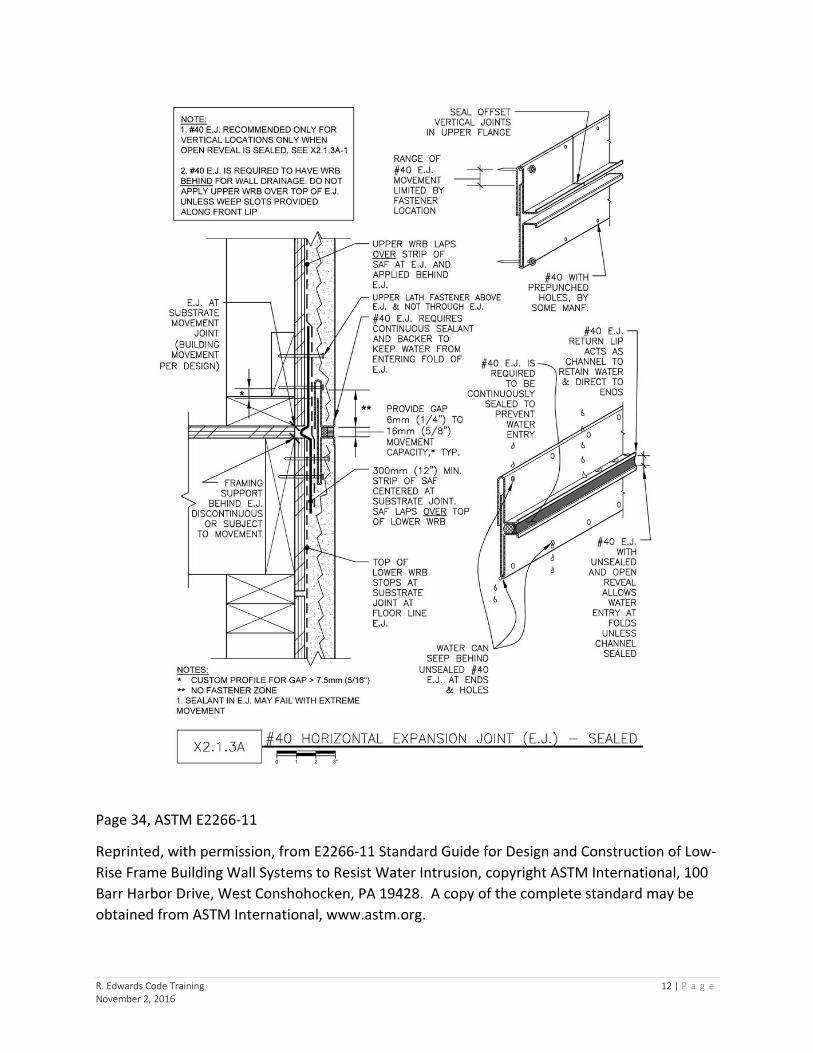
Page 34, ASTM E2266-11
Reprinted, with permission, from E2266-11 Standard Guide for Design and Construction of Low-Rise Frame Building Wall Systems to Resist Water Intrusion, copyright ASTM International, 100 Barr Harbor Drive, West Conshohocken, PA 19428. A copy of the complete standard may be obtained from ASTM International, www.astm.org.

R. Edwards Code Training 13 | P a g e November 2, 2016
Page 37, ASTM E2266-11
Reprinted, with permission, from E2266-11 Standard Guide for Design and Construction of Low-Rise Frame Building Wall Systems to Resist Water Intrusion, copyright ASTM International, 100 Barr Harbor Drive, West Conshohocken, PA 19428. A copy of the complete standard may be obtained from ASTM International, www.astm.org.

R. Edwards Code Training 14 | P a g e November 2, 2016
Page 38, ASTM E2266-11
Reprinted, with permission, from E2266-11 Standard Guide for Design and Construction of Low-Rise Frame Building Wall Systems to Resist Water Intrusion, copyright ASTM International, 100 Barr Harbor Drive, West Conshohocken, PA 19428. A copy of the complete standard may be obtained from ASTM International, www.astm.org.

R. Edwards Code Training 15 | P a g e November 2, 2016
Page 39, ASTM E2266-11
Reprinted, with permission, from E2266-11 Standard Guide for Design and Construction of Low-Rise Frame Building Wall Systems to Resist Water Intrusion, copyright ASTM International, 100 Barr Harbor Drive, West Conshohocken, PA 19428. A copy of the complete standard may be obtained from ASTM International