Peridynamic Modeling of Localization in Ductile Metalsdjlittl/docs/Littlewood_IWCMM2012.pdf · ①...
18
1 Sandia Na)onal Laboratories is a mul) program laboratory managed and operated by Sandia Corpora)on, a wholly owned subsidiary of Lockheed Mar)n Corpora)on, for the U.S. Department of Energy's Na)onal Nuclear Security Administra)on under contract DEAC0494AL85000. . Peridynamic Modeling of Localization in Ductile Metals International Workshop on Computational Mechanics of Materials IWCMM XXII 26 September 2012 SAND2012-8102C David Littlewood Sandia National Laboratories John Foster University of Texas at San Antonio Brad Boyce Sandia National Laboratories
Transcript of Peridynamic Modeling of Localization in Ductile Metalsdjlittl/docs/Littlewood_IWCMM2012.pdf · ①...

1 Sandia Na)onal Laboratories is a mul) program laboratory managed and operated by Sandia Corpora)on, a wholly owned subsidiary of Lockheed Mar)n Corpora)on, for the U.S. Department of Energy's Na)onal Nuclear Security Administra)on under contract DE-‐AC04-‐94AL85000. .
Peridynamic Modeling of Localization in Ductile Metals
International Workshop on Computational Mechanics of Materials IWCMM XXII
26 September 2012
SAND2012-8102C
David Littlewood Sandia National Laboratories
John Foster University of Texas
at San Antonio
Brad Boyce Sandia National Laboratories

2
Peridynamics is a mathematical theory that unifies the mechanics of continuous media, cracks, and discrete particles
WHAT IS PERIDYNAMICS?
HOW DOES IT WORK?
S.A. Silling. Reformulation of elasticity theory for discontinuities and long-range forces. Journal of the Mechanics and Physics of Solids, 48:175-209, 2000.
Silling, S.A. and Lehoucq, R. B. Peridynamic Theory of Solid Mechanics. Advances in Applied Mechanics 44:73-168, 2010.
§ Peridynamics is a nonlocal extension of continuum mechanics § Remains valid in presence of discontinuities, including cracks § Balance of linear momentum is based on an integral equation:
Peridynamics
The point X interacts directly with all points
within its horizon

3
§ Peridynamic bonds connect any two material points that interact directly § Peridynamic forces are determined by force states acting on bonds
§ Force states are determined by constitutive laws and are functions of the deformations of all points within a neighborhood
§ Material failure is modeled through the breaking of peridynamic bonds - Example: critical stretch bond breaking law
DISCRETIZATION OF A PERIDYNAMIC BODY
Peridynamics
CONSTITUTIVE LAWS IN PERIDYNAMICS
A body may be represented by a finite number of sphere elements

4
LINEAR PERIDYNAMIC SOLID (ELASTIC MODEL)
State-based Peridynamic Material Models
ELASTIC-PLASTIC MODEL
S.A. Silling, M. Epton, O. Weckner, J. Xu, and E. Askari, Peridynamic states and constitutive modeling, Journal of Elasticity, 88, 2007.
J.A. Mitchell. A nonlocal, ordinary, state-based plasticity model for peridynamics. Sandia Report SAND2011-3166, 2011.

5
APPROACH: NON-ORDINARY STATE-BASED PERIDYNAMICS
Adaptation of Classical Material Models for Peridynamics
S. Silling, M. Epton, O. Weckner, J. Xu, and E. Askari. Peridynamic states and constitutive modeling. Journal of Elasticity, 88(2):151-184, 2007.
① Compute regularized deformation gradient
② Classical material model computes stress based on regularized deformation gradient
③ Convert stress to peridynamic force densities
④ Apply peridynamic hourglass forces as required to stabilize simulation (optional)
§ Apply existing (local) constitutive models within nonlocal peridynamic framework § Utilize approximate deformation gradient based on positions and deformations of all
elements in the neighborhood

6
APPROACH: PENALIZE DEFORMATION THAT DEVIATES FROM REGULARIZED DEFORMATION GRADIENT
Suppression of Zero-Energy Modes
Predicted location of neighbor Hourglass vector
Hourglass force
Hourglass vector projected onto bond
7
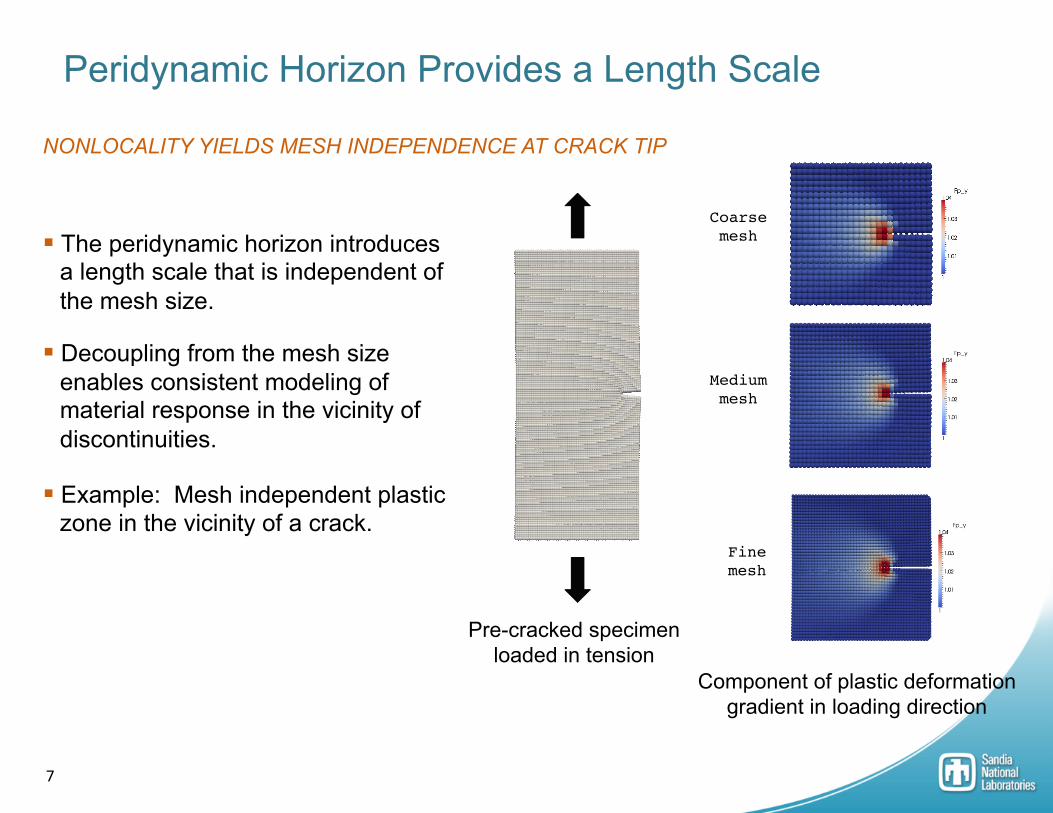
Peridynamic Horizon Provides a Length Scale
Coarse mesh!
Component of plastic deformation gradient in loading direction
Medium mesh!
Fine mesh!
Pre-cracked specimen loaded in tension
§ The peridynamic horizon introduces a length scale that is independent of the mesh size.
§ Decoupling from the mesh size enables consistent modeling of material response in the vicinity of discontinuities.
§ Example: Mesh independent plastic zone in the vicinity of a crack.
NONLOCALITY YIELDS MESH INDEPENDENCE AT CRACK TIP

8
§ Interatomic forces
§ Van der Waals forces
§ Force between a pair of atoms as they are separated:
§ Net force between half-space and sphere occurs over a much larger length scale*
Can the Peridynamic Horizon Have Physical Meaning?
Atom i
Atom j
*See J. Israelachvili, Intermolecular and Surfaces Forces, pp. 177.
[Courtesy S. Silling]
MANY PHYSICAL PROBLEMS HAVE NATURAL LENGTH SCALE(S)

9
NONLOCALITY AS A RESULT OF HOMOGENIZATION
Physical Interpretation of Peridynamic Horizon
§ Homogenization (neglecting natural length scales) often leads to poor results
§ Nonlocality (length scale) can be an essential feature of a realistic homogenized model of a heterogeneous material
§ Example: Concrete indentor
[Courtesy S. Silling]

10
PROPOSED EXPERIMENTAL METHOD FOR MEASURING THE PERIDYNAMIC HORIZON
Physical Interpretation of Peridynamic Horizon
Time
Free surface velocity
Peridynamic 1D
Visar
Spread Projec)le Sample
Visar
Laser
[Courtesy S. Silling]
§ Measure how much a step wave spreads as it goes through a heterogeneous sample
§ Fit the horizon in a peridynamic model to match observed spread
Local model would predict zero spread

11
§ Local models contain no length scale
§ Higher-order gradients introduce length scale in a weak sense
§ Peridynamics is a (strongly) nonlocal model
Peridynamics and Higher-Order Gradient Methods
Peridynamic model (nonlocal)
Higher-order gradient model (weakly nonlocal)
Local model
S.A. Silling and R.B. Lehoucq, Convergence of peridynamics to classical elasticity theory, Journal of Elasticity, 93(1), 2008.
Pablo Seleson, Michael L. Parks, Max Gunzburger, and Richard B. Lehoucq. Peridynamics as an upscaling of molecular dynamics. Multiscale Modeling and Simulation, 8(1), 2009.
Dimensional analysis shows that sqrt(b/a) has units of length

12
§ Test setup: § 304L stainless steel (very ductile) § Quasi-static loading conditions § Standard tensile test results provided for
calibration
Necking Experiment CAN A PERIDYNAMIC MODEL PREDICT LOCALIZATION?
§ Challenge: § Predict force and engineering strain at peak load § Predict engineering strain when force has dropped to 95% of peak load § Predict chord lengths when force has dropped to 95% of peak load
Test geometry
Calibration geometry

13
§ Force versus engineering strain
§ Cross-sectional area at the point where the force dropped to 75% of peak load
Necking Experiment: Calibration of Peridynamic Model
Cross-sectional Area Initial value: 0.0310 in2
At 75% peak load: 0.0107 in2
TENSILE TEST CALIBRATION DATA

14
Necking Experiment: Calibration of Peridynamic Model
200 300 400 500 600 700 800 900
1000 1100 1200 1300
0 0.1 0.2 0.3 0.4 0.5 0.6 0.7 0.8 0.9
Har
deni
ng C
urve
(MPa
)
Strain (mm/mm)
Hardening Curve
ELASTIC-PLASTIC MODEL WITH PIECEWISE LINEAR HARDENING CURVE
§ Quasi-static simulations carried out with Sierra/SolidMechanics
§ Initial calibration taken from classical finite-element model of tensile test (automated calibration tool)
§ Hardening curve manually adjusted past ultimate tensile strength
Young’s Modulus 199.95e3 MPa
Poisson’s Ra)o 0.285
Yield Stress 220.0 MPa

15
Necking Experiment: Calibration of Peridynamic Model
Cross-sectional Area Initial value: 0.031 in2
Simulation at 75% peak load: 0.0129 in2
0
0.005
0.01
0.015
0.02
0.025
0.03
0.035
0 0.1 0.2 0.3 0.4 0.5 0.6 0.7 0.8 0.9
Cros
s Sec
tiona
l Are
a (in
2 )
Engineering Strain (in/in)
Peridynamic SimulationExperimental Result
LOCALIZATION IN TENSILE TEST

16
Necking Experiment: Test Geometry
0
0.2
0.4
0.6
0.8
1
A B C D E F G
Leng
th (i
n)
Chord Label
Experimental ResultsPeridynamic Simulation
0
500
1000
1500
2000
2500
3000
3500
4000
0 0.1 0.2 0.3 0.4 0.5 0.6 0.7 0.8 0.9
Forc
e (lb
f)
Engineering Strain (in/in)
Experimental ResultsPeridynamic Simulation
§ Peridynamic horizon and mesh refinement were sufficient for calibration geometry but insufficient for test geometry
§ Failed to predict response of test geometry
DIRECT TRANSFER OF CALIBRATION PARAMETERS
Experimental DIC image [Boyce]
Simulation result

17
Necking Experiment: Test Geometry
0
0.2
0.4
0.6
0.8
1
A B C D E F G
Leng
th (i
n)
Chord Label
Experimental ResultsPeridynamic Simulation
0
500
1000
1500
2000
2500
3000
0 0.05 0.1 0.15 0.2 0.25 0.3 0.35 0.4 0.45
Forc
e (lb
f)
Engineering Strain (in/in)
Experimental ResultsPeridynamic Simulation
§ Peridynamic horizon reduced from 1.055 mm to 0.353 mm
§ Mesh density increased from 189K elements to 1,507K elements
§ Dramatically improved agreement between peridynamic model and experimental data
REDUCTION OF PERIDYNAMIC HORIZON
Experimental DIC image [Boyce]
Simulation result

18
Questions?
RESOURCES
Advanced Simula)on and Compu)ng (ASC)
h_p://www.sandia.gov/asc/
Peridigm: A publicly-‐available peridynamics code
h_ps://soaware.sandia.gov/trac/peridigm/
David Littlewood [email protected]!