Performance Testing A 30 Cubic Inch Bourke...
9
PERFORMANCE TESTING 30 CUBIC INCH BOURKE ENGINE By J. David Kirk, EAA 88934 2252 Ottawa Road Waukegan,IL 60085 1ONG ALL OF the interesting and unusual inter- nal combustion engines invented in the last 70 years, the engines designed and built by Russell Bourke must rank as some of the most controversial. Operating on the same mechanical principles, all the engines Bourke built during his lifetime were, according to Bourke, capa- ble of remarkable horsepower outputs and thermal ef- ficiencies. Unfortunately, Bourke died in 1968, having left behind no documented evidence of his engines' amazing performance capabilities. However, a compila- tion of his writings were published in a book entitled Bourke Engine Documentary; but while this serves to heighten interest, it does not provide for any detailed in- formation concerning engine design, construction or per- formance. Of the many devotees and enthusiasts who have obtained some of the original engines or con- structed their own Bourke engines, few have claimed to duplicate Bourke's stated performance and running characteristics, and to this day there is no known case of any of these individuals publishing any information on their findings. My interest in the Bourke engine began in the spring of 1972 after reading an article about Russell Bourke in an EAA publication entitled Engines, Vol- ume II. Some of the more interesting points discussed in the article that really stirred my curiosity was the en- gines' claimed ability to develop a great deal of horse- power with excellent fuel economy, while operating on lean air/fuel ratios on low octane fuels. Such claims prompted me to ask myself why wasn't such a remark- able engine in more widespread use and could it be possi- ble that no one recognized the virtues of this discovery made by Bourke? I was a first-year engineering student at this time and since my interest pertained to engines of all types, especially two-strokes, the Bourke seemed to offer itself as an excellent college research project. At the 1972 EAA Annual Fly-In at Oshkosh, Wis- consin, I was fortunate enough to meet a gentleman named Nicholas Fucille who informed me that Mr. Bourke was survived by his wife, Lois, and from her I would be able to obtain a copy of the Bourke Engine Documentary. I was also informed of the existence of a small manufacturing firm in Boulder City, Nevada by the name of Vaux Enterprises that would build a 30 cubic inch Bourke engine replica on special order. That evening I wrote to Vaux Enterprises requesting infor- mation and prices on their engine, and ordered the documentary from Lois Bourke. It was through many hours of studying this documentary that I became acquainted with the Bourke theory of combustion and the principles by which he de- 52 MARCH 1980 signed all of his engines. According to Bourke, an in- stantaneous explosion, or detonation of the air/fuel mix- ture in a suitably designed spark-ignition engine would release far more usable energy than progressively burn- ing the mixture as is the practice in the normal combus- tion process. The detonation of a lean air/fuel mixture was, so Bourke thought, the key to developing high power outputs with low fuel consumption. Consequently, it was Bourke's firm belief that detonation should be en- couraged and not surpressed as is now done by doping fuels with anti-knock additives. Thus, Bourke's sole aim was to design an engine that would run on the detona- tion of a low-grade, hydrocarbon fuel. In order to pro- mote this combustion phenomena, Bourke designed his engines to operate with high compression ratios, low grade, low octane fuels, lean air/fuel ratios, considerable mixture preheating, and highly advanced spark timings. It was a well-known fact, even in Bourke's day, that a conventional spark-ignition engine will tolerate detona- tion only for brief periods of time without incurring se- vere mechanical damage to pistons and valves. This damage is caused by the high heat and pressures as- sociated with the detonation phenomena. Bourke's solu- tion to this problem was to eliminate the articulating connecting rod used in conventional engines by employ- ing a modified Scotch-yoke crank mechanism coupled with the two-stroke engine cycle. The result was a lightweight and structurally strong engine configura- tion. Bourke's modification of the Scotch-yoke consisted of replacing the traditional crankpin slider block with a roller assembly, which greatly decreased friction and made this crank mechanism applicable to a high-speed engine. Figure 1 shows the basic arrangement of the Bourke 30 cubic inch engine, which consists of two horizontally opposed cylinders attached to a common crankcase. Con- ventional piston controlled inlet, transfer, and exhaust ports are employed, as used in standard two-stroke prac- - INLET PASSAGE -CARBURETOR LOCATION TRANSFER PASSAGE -YOKE PLATES L PISTON CRANKPIN BEARING CDANKCASE -PISTON HOD (EARING FIG. 1
Transcript of Performance Testing A 30 Cubic Inch Bourke...
PERFORMANCE TESTING30 CUBIC INCH
BOURKE ENGINE
By J. David Kirk, EAA 889342252 Ottawa Road
Waukegan,IL 60085
1ONG ALL OF the interesting and unusual inter-nal combustion engines invented in the last 70 years,the engines designed and built by Russell Bourke mustrank as some of the most controversial. Operating onthe same mechanical principles, all the engines Bourkebuilt during his lifetime were, according to Bourke, capa-ble of remarkable horsepower outputs and thermal ef-ficiencies. Unfortunately, Bourke died in 1968, havingleft behind no documented evidence of his engines'amazing performance capabilities. However, a compila-tion of his writings were published in a book entitledBourke Engine Documentary; but while this serves toheighten interest, it does not provide for any detailed in-formation concerning engine design, construction or per-formance. Of the many devotees and enthusiasts whohave obtained some of the original engines or con-structed their own Bourke engines, few have claimed toduplicate Bourke's stated performance and runningcharacteristics, and to this day there is no known case ofany of these individuals publishing any information ontheir findings.
My interest in the Bourke engine began in thespring of 1972 after reading an article about RussellBourke in an EAA publication entitled Engines, Vol-ume II. Some of the more interesting points discussed inthe article that really stirred my curiosity was the en-gines' claimed ability to develop a great deal of horse-power with excellent fuel economy, while operating onlean air/fuel ratios on low octane fuels. Such claimsprompted me to ask myself why wasn't such a remark-able engine in more widespread use and could it be possi-ble that no one recognized the virtues of this discoverymade by Bourke? I was a first-year engineering studentat this time and since my interest pertained to enginesof all types, especially two-strokes, the Bourke seemedto offer itself as an excellent college research project.
At the 1972 EAA Annual Fly-In at Oshkosh, Wis-consin, I was fortunate enough to meet a gentlemannamed Nicholas Fucille who informed me that Mr.Bourke was survived by his wife, Lois, and from her Iwould be able to obtain a copy of the Bourke EngineDocumentary. I was also informed of the existence of asmall manufacturing firm in Boulder City, Nevada bythe name of Vaux Enterprises that would build a 30cubic inch Bourke engine replica on special order. Thatevening I wrote to Vaux Enterprises requesting infor-mation and prices on their engine, and ordered thedocumentary from Lois Bourke.
It was through many hours of studying thisdocumentary that I became acquainted with the Bourketheory of combustion and the principles by which he de-52 MARCH 1980
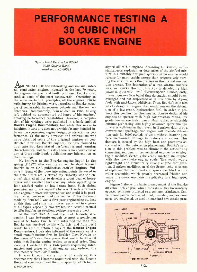
signed all of his engines. According to Bourke, an in-stantaneous explosion, or detonation of the air/fuel mix-ture in a suitably designed spark-ignition engine wouldrelease far more usable energy than progressively burn-ing the mixture as is the practice in the normal combus-tion process. The detonation of a lean air/fuel mixturewas, so Bourke thought, the key to developing highpower outputs with low fuel consumption. Consequently,it was Bourke's firm belief that detonation should be en-couraged and not surpressed as is now done by dopingfuels with anti-knock additives. Thus, Bourke's sole aimwas to design an engine that would run on the detona-tion of a low-grade, hydrocarbon fuel. In order to pro-mote this combustion phenomena, Bourke designed hisengines to operate with high compression ratios, lowgrade, low octane fuels, lean air/fuel ratios, considerablemixture preheating, and highly advanced spark timings.It was a well-known fact, even in Bourke's day, that aconventional spark-ignition engine will tolerate detona-tion only for brief periods of time without incurring se-vere mechanical damage to pistons and valves. Thisdamage is caused by the high heat and pressures as-sociated with the detonation phenomena. Bourke's solu-tion to this problem was to eliminate the articulatingconnecting rod used in conventional engines by employ-ing a modified Scotch-yoke crank mechanism coupledwith the two-stroke engine cycle. The result was alightweight and structurally strong engine configura-tion. Bourke's modification of the Scotch-yoke consistedof replacing the traditional crankpin slider block with aroller assembly, which greatly decreased friction andmade this crank mechanism applicable to a high-speedengine.
Figure 1 shows the basic arrangement of the Bourke30 cubic inch engine, which consists of two horizontallyopposed cylinders attached to a common crankcase. Con-ventional piston controlled inlet, transfer, and exhaustports are employed, as used in standard two-stroke prac-
- INLET PASSAGE
-CARBURETOR LOCATION
TRANSFER PASSAGE
-YOKE PLATES L PISTONCRANKPIN BEARING
CDANKCASE
-PISTON HOD (EARING
FIG. 1
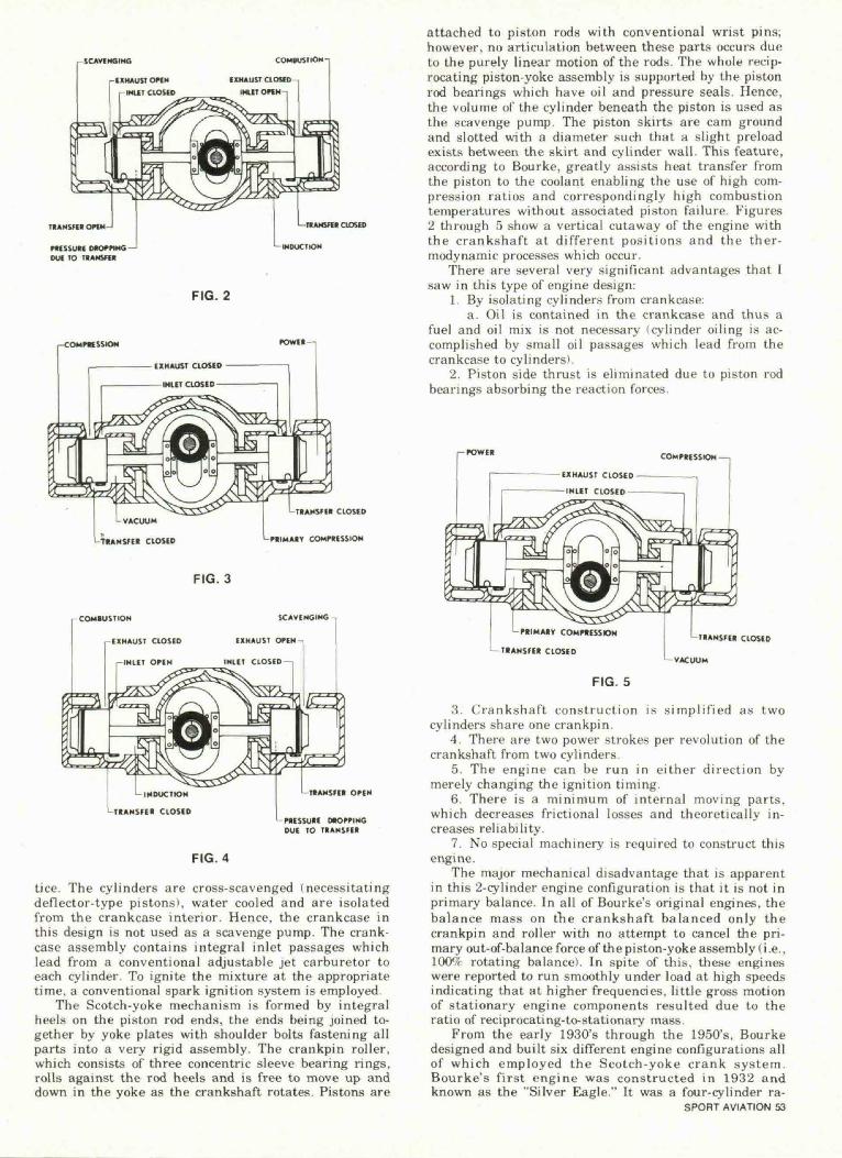
co>mstiON-|
HONSHU Off*-I
PtCSSUIE OCOrPIHGDUE IO TIAMSfU
LTIAMSni CIOSID
'-IMOUCIION
FIG. 2
.-COMMISSION fOWIt-,
>-VACUUM
LTRAMSHI CLOSED
COMIUSIKJH
EXHAUST CLOSED
I-IHUT OPEN
LTIANSFII CLOSED
PIIMAIT COMMISSION
FIG. 3
SCAVIMGINO -,
EXHAUST OPEN-,
INIIT CLOSED
TIANSKH OPEN
CHOPPINGDUE TO TIANSFEI
FIG. 4
tice. The cylinders are cross-scavenged (necessitatingdeflector-type pistons), water cooled and are isolatedfrom the crankcase interior. Hence, the crankcase inthis design is not used as a scavenge pump. The crank-case assembly contains integral inlet passages whichlead from a conventional adjustable jet carburetor toeach cylinder. To ignite the mixture at the appropriatetime, a conventional spark ignition system is employed.
The Scotch-yoke mechanism is formed by integralheels on the piston rod ends, the ends being joined to-gether by yoke plates with shoulder bolts fastening allparts into a very rigid assembly. The crankpin roller,which consists of three concentric sleeve bearing rings,rolls against the rod heels and is free to move up anddown in the yoke as the crankshaft rotates. Pistons are
attached to piston rods with conventional wrist pins;however, no articulation between these parts occurs dueto the purely linear motion of the rods. The whole recip-rocating piston-yoke assembly is supported by the pistonrod bearings which have oil and pressure seals. Hence,the volume of the cylinder beneath the piston is used asthe scavenge pump. The piston skirts are cam groundand slotted with a diameter such that a slight preloadexists between the skirt and cylinder wall. This feature,according to Bourke, greatly assists heat transfer fromthe piston to the coolant enabling the use of high com-pression ratios and correspondingly high combustiontemperatures without associated piston failure. Figures2 through 5 show a vertical cutaway of the engine withthe crankshaft at different positions and the ther-modynamic processes which occur.
There are several very significant advantages that Isaw in this type of engine design:
1. By isolating cylinders from crankcase:a. Oil is contained in the crankcase and thus a
fuel and oil mix is not necessary (cylinder oiling is ac-complished by small oil passages which lead from thecrankcase to cylinders).
2. Piston side thrust is eliminated due to piston rodbearings absorbing the reaction forces.
r-POWER COMPRESSION —|
UPRIMARV COMMISSION
— TRANSFER CLOSED
FIG. 5
TRANSFER CLOSED
L VACUUM
3. Crankshaft construct ion is s i m p l i f i e d as twocylinders share one crankpin.
4. There are two power strokes per revolution of thecrankshaft from two cylinders.
5. The engine can be run in either direction bymerely changing the ignition timing.
6. There is a min imum of internal moving parts,which decreases frictional losses and theoretically in-creases reliability.
7. No special machinery is required to construct thisengine.
The major mechanical disadvantage that is apparentin this 2-cylinder engine configuration is that it is not inprimary balance. In all of Bourke's original engines, thebalance mass on the crankshaft balanced only thecrankpin and roller with no attempt to cancel the pri-mary out-of-balance force of the piston-yoke assembly (i.e.,1009f rotating balance). In spite of this, these engineswere reported to run smoothly under load at high speedsindicating that at higher frequencies, little gross motionof stationary engine components resulted due to theratio of reciprocating-to-stationary mass.
From the early 1930's through the 1950's, Bourkedesigned and built six different engine configurations allof which employed the Scotch-yoke crank system.Bourke's first engine was constructed in 1932 andknown as the "Silver Eagle." It was a four-cylinder ra-
SPORT AVIATION 53
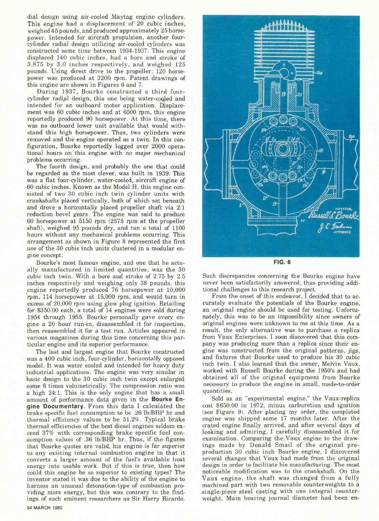
dial design using air-cooled Maytag engine cylinders.This engine had a displacement of 20 cubic inches,weighed 45 pounds, and produced approximately 25 horse-power. Intended for aircraft propulsion, another four-cylinder radial design utilizing air-cooled cylinders wasconstructed some time between 1934-1937. This enginedisplaced 140 cubic inches, had a bore and stroke of3.875 by 3.0 inches respectively, and weighed 125pounds. Using direct drive to the propeller, 120 horse-power was produced at 3200 rpm. Patent drawings ofthis engine are shown in Figures 6 and 7.
During 1937, Bourke constructed a third four-cylinder radi01 design, this one being water-cooled andintended for an outboard motor application. Displace-ment was 60 cubic inches and at 6500 rpm, this enginereportedly produced 90 horsepower. At this time, therewas no outboard lower unit available that would with-stand this high horsepower. Thus, two cylinders wereremoved and the engine operated as a twin. In this con-figuration, Bourke reportedly logged over 2000 opera-tional hours on this engine with no major mechanicalproblems occurring.
The fourth design, and probably the one that couldbe regarded as the most clever, was built in 1939. Thiswas a fiat four-cylinder, water-cooled, aircraft engine of60 cubic inches. Known as the Model H, this engine con-sisted of two 30 cubic inch twin cylinder units withcrankshafts placed vertically, both of which sat beneathand drove a horizontally placed propeller shaft via 2:1reduction bevel gears. The engine was said to produce60 horsepower at 5150 rpm (2575 rpm at the propellershaft), weighed 95 pounds dry, and ran a total of 1100hours without any mechanical problems occurring. Thisarrangement as shown in Figure 8 represented the firstuse of the 30 cubic inch units clustered in a modular en-gine concept.
Bourke's most famous engine, and one that he actu-ally manufactured in limited quantities, was the 30cubic inch twin. With a bore and stroke of 2.75 by 2.5inches respectively and weighing only 38 pounds, thisengine reportedly produced 76 horsepower at 10,000rpm, 114 horsepower at 15,000 rpm, and would turn inexcess of 20,000 rpm using glow plug ignition. Retailingfor $350.00 each, a total of 14 engines were sold during1954 through 1955. Bourke personally gave every en-gine a 20 hour run-in, disassembled it for inspection,then reassembled it for a test run. Articles appeared invarious magazines during this time concerning this par-ticular engine and its superior performance.
The last and largest engine that Bourke constructedwas a 400 cubic inch, four-cylinder, horizontally opposedmodel. It was water cooled and intended for heavy dutyindustrial applications. The engine was very similar inbasic design to the 30 cubic inch twin except enlargedsome 6 times volumetrically. The compression ratio wasa high 24:1. This is the only engine that has a smallamount of performance data given in the Bourke En-gine Documentary. From this data I calculated thebrake specific fuel consumption to be .26 Ib/BHP hr andthermal efficiency values to be 51.2%. Typical brakethermal efficiencies of the best diesel engines seldom ex-ceed 37% with corresponding brake specific fuel con-sumption values of .36 Ib/BHP hr. Thus, if the figuresthat Bourke quotes are valid, his engine is far superiorto any existing internal combustion engine in that itconverts a larger amount of the fuel's available heatenergy into usable work. But if this is true, then howcould this engine be so superior to existing types? Theinventor stated it was due to the ability of the engine toharness an unusual detonation-type of combustion pro-viding more energy, but this was contrary to the find-ings of such eminent researchers as Sir Harry Ricardo.54 MARCH 1980
FIG. 6
Such discrepancies concerning the Bourke engine havenever been satisfactorily answered, thus providing addi-tional challenges to this research project.
From the onset of this endeavor, I decided that to ac-curately evaluate the potentials of the Bourke engine,an original engine should be used for testing. Unfortu-nately, this was to be an impossibility since owners oforiginal engines were unknown to me at this time. As aresult, the only alternative was to purchase a replicafrom Vaux Enterprises. I soon discovered that this com-pany was producing more than a replica since their en-gine was constructed from the original patterns, jigs,and fixtures that Bourke used to produce his 30 cubicinch twin. I also learned that the owner, Melvin Vaux,worked with Russell Bourke during the 1950's and hadobtained all of the original equipment from Bourkenecessary to produce the engine in small, made-to-orderquantities.
Sold as an "experimental engine," the Vaux-replicacost $650.00 in 1972, minus carburetion and ignition(see Figure 9). After placing my order, the completedengine was shipped some 17 months later. After thecrated engine finally arrived, and after several days oflooking and admiring, I carefully disassembled it forexamination. Comparing the Vaux engine to the draw-ings made by Donald Smail of the original pre-production 30 cubic inch Bourke engine, I discoveredseveral changes that Vaux had made from the originaldesign in order to facilitate his manufacturing. The mostnoticeable modification was to the crankshaft. On theVaux engine, the shaft was changed from a fullymachined part with two removable counterweights to asingle-piece steel casting with one integral counter-weight. Main bearing journal diameter had been en-
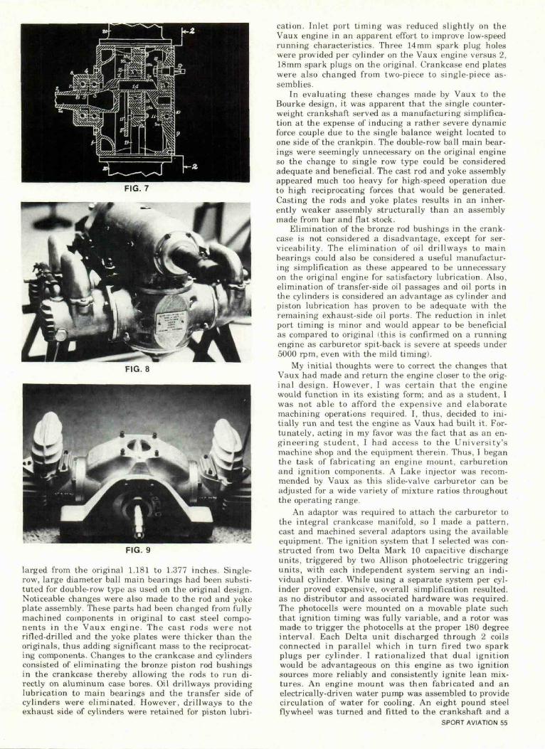
FIG. 7
FIG. 8
FIG. 9
larged from the original 1.181 to 1.377 inches. Single-row, large diameter ball main bearings had been substi-tuted for double-row type as used on the original design.Noticeable changes were also made to the rod and yokeplate assembly. These parts had been changed from fullymachined components in original to cast steel compo-nents in the Vaux engine. The cast rods were notrifled-drilled and the yoke plates were thicker than theoriginals, thus adding significant mass to the reciprocat-ing components. Changes to the crankcase and cylindersconsisted of eliminating the bronze piston rod bushingsin the crankcase thereby allowing the rods to run di-rectly on a luminum case bores. Oil drillways providinglubrication to main bearings and the transfer side ofcylinders were eliminated. However, drillways to theexhaust side of cylinders were retained for piston lubri-
cation. Inlet port t iming was reduced sl ightly on theVaux engine in an apparent effort to improve low-speedrunning characteristics. Three 14mm spark plug holeswere provided per cylinder on the Vaux engine versus 2,18mm spark plugs on the original. Crankcase end plateswere also changed from two-piece to single-piece as-semblies.
In evaluating these changes made by Vaux to theBourke design, it was apparent that the single counter-weight crankshaft served as a manufacturing simplifica-tion at the expense of inducing a rather severe dynamicforce couple due to the single balance weight located toone side of the crankpin. The double-row ball main bear-ings were seemingly unnecessary on the original engineso the change to single row type could be consideredadequate and beneficial. The cast rod and yoke assemblyappeared much too heavy for high-speed operation dueto high reciprocating forces that would be generated.Casting the rods and yoke plates results in an inher-ently weaker assembly structurally than an assemblymade from bar and flat stock.
Elimination of the bronze rod bushings in the crank-case is not considered a disadvantage, except for ser-viceability. The e l iminat ion of oil dr i l lways to mainbearings could also be considered a useful manufactur-ing simplification as these appeared to be unnecessaryon the original engine for satisfactory lubrication. Also,elimination of transfer-side oil passages and oil ports inthe cylinders is considered an advantage as cylinder andpiston lubrication has proven to be adequate with theremaining exhaust-side oil ports. The reduction in inletport timing is minor and would appear to be beneficialas compared to original ( this is confirmed on a runningengine as carburetor spit-back is severe at speeds under5000 rpm, even with the mild timing).
My init ial thoughts were to correct the changes thatVaux had made and return the engine closer to the orig-inal design. However, I was certain that the enginewould function in its existing form; and as a student, Iwas not able to afford the expensive and elaboratemachining operations required. I, thus, decided to ini-tially run and test the engine as Vaux had built it. For-tunately, acting in my favor was the fact that as an en-gineering student, I had access to the University'smachine shop and the equipment therein. Thus, I beganthe task of fabricating an engine mount, carburetionand ignition components. A Lake injector was recom-mended by Vaux as this slide-valve carburetor can beadjusted for a wide variety of mixture ratios throughoutthe operating range.
An adaptor was required to attach the carburetor tothe integral crankcase manifold, so I made a pattern,cast and machined several adaptors using the availableequipment. The ignition system that I selected was con-structed from two Delta Mark 10 capacitive dischargeunits, triggered by two Allison photoelectric triggeringunits, with each independent system serving an indi-vidual cylinder. While using a separate system per cyl-inder proved expensive, overall simplification resulted,as no distributor and associated hardware was required.The photocells were mounted on a movable plate suchthat ignition timing was fully variable, and a rotor wasmade to trigger the photocells at the proper 180 degreeinterval. Each Delta unit discharged through 2 coilsconnected in parallel which in turn fired two sparkplugs per cylinder. I rationalized that dual ignitionwould be advantageous on this engine as two ignitionsources more reliably and consistently ignite lean mix-tures. An engine mount was then fabricated and anelectrically-driven water pump was assembled to providecirculation of water for cooling. An eight pound steelflywheel was turned and fitted to the crankshaft and a
SPORT AVIATION 55
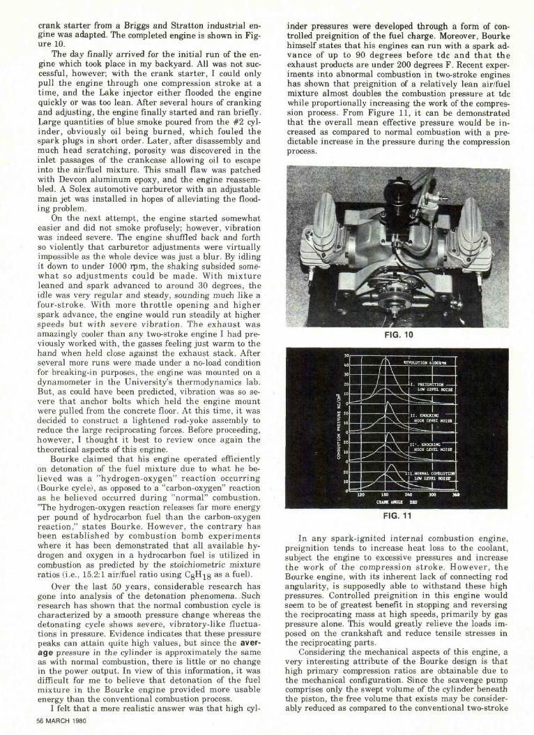
crank starter from a Briggs and Stratton industrial en-gine was adapted. The completed engine is shown in Fig-ure 10.
The day finally arrived for the initial run of the en-gine which took place in my backyard. All was not suc-cessful, however; with the crank starter, I could onlypull the engine through one compression stroke at atime, and the Lake injector either flooded the enginequickly or was too lean. After several hours of crankingand adjusting, the engine finally started and ran briefly.Large quantities of blue smoke poured from the #2 cyl-inder, obviously oil being burned, which fouled thespark plugs in short order. Later, after disassembly andmuch head scratching, porosity was discovered in theinlet passages of the crankcase allowing oil to escapeinto the air/fuel mixture. This small flaw was patchedwith Devcon aluminum epoxy, and the engine reassem-bled. A Solex automotive carburetor with an adjustablemain jet was installed in hopes of alleviating the flood-ing problem.
On the next attempt, the engine started somewhateasier and did not smoke profusely; however, vibrationwas indeed severe. The engine shuffled back and forthso violently that carburetor adjustments were virtuallyimpossible as the whole device was just a blur. By idlingit down to under 1000 rpm, the shaking subsided some-what so adjustments could be made. With mixtureleaned and spark advanced to around 30 degrees, theidle was very regular and steady, sounding much like afour-stroke. With more throttle opening and higherspark advance, the engine would run steadily at higherspeeds but with severe vibration. The exhaust wasamazingly cooler than any two-stroke engine I had pre-viously worked with, the gasses feeling just warm to thehand when held close against the exhaust stack. Afterseveral more runs were made under a no-load conditionfor breaking-in purposes, the engine was mounted on adynamometer in the University's thermodynamics lab.But, as could have been predicted, vibration was so se-vere that anchor bolts which held the engine mountwere pulled from the concrete floor. At this time, it wasdecided to construct a lightened rod-yoke assembly toreduce the large reciprocating forces. Before proceeding,however, I thought it best to review once again thetheoretical aspects of this engine.
Bourke claimed that his engine operated efficientlyon detonation of the fuel mixture due to what he be-lieved was a "hydrogen-oxygen" reaction occurring(Bourke cycle), as opposed to a "carbon-oxygen" reactionas he believed occurred during "normal" combustion."The hydrogen-oxygen reaction releases far more energyper pound of hydrocarbon fuel than the carbon-oxygenreaction," states Bourke. However, the contrary hasbeen established by combustion bomb experimentswhere it has been demonstrated that all available hy-drogen and oxygen in a hydrocarbon fuel is utilized incombustion as predicted by the stoichiometric mixtureratios (i.e., 15.2:1 air/fuel ratio using CgH^g as a fuel).
Over the last 50 years, considerable research hasgone into analysis of the detonation phenomena. Suchresearch has shown that the normal combustion cycle ischaracterized by a smooth pressure change whereas thedetonating cycle shows severe, vibratory-like fluctua-tions in pressure. Evidence indicates that these pressurepeaks can attain quite high values, but since the aver-age pressure in the cylinder is approximately the sameas with normal combustion, there is little or no changein the power output. In view of this information, it wasdifficult for me to believe that detonation of the fuelmixture in the Bourke engine provided more usableenergy than the conventional combustion process.
I felt that a more realistic answer was that high cyl-56 MARCH 1980
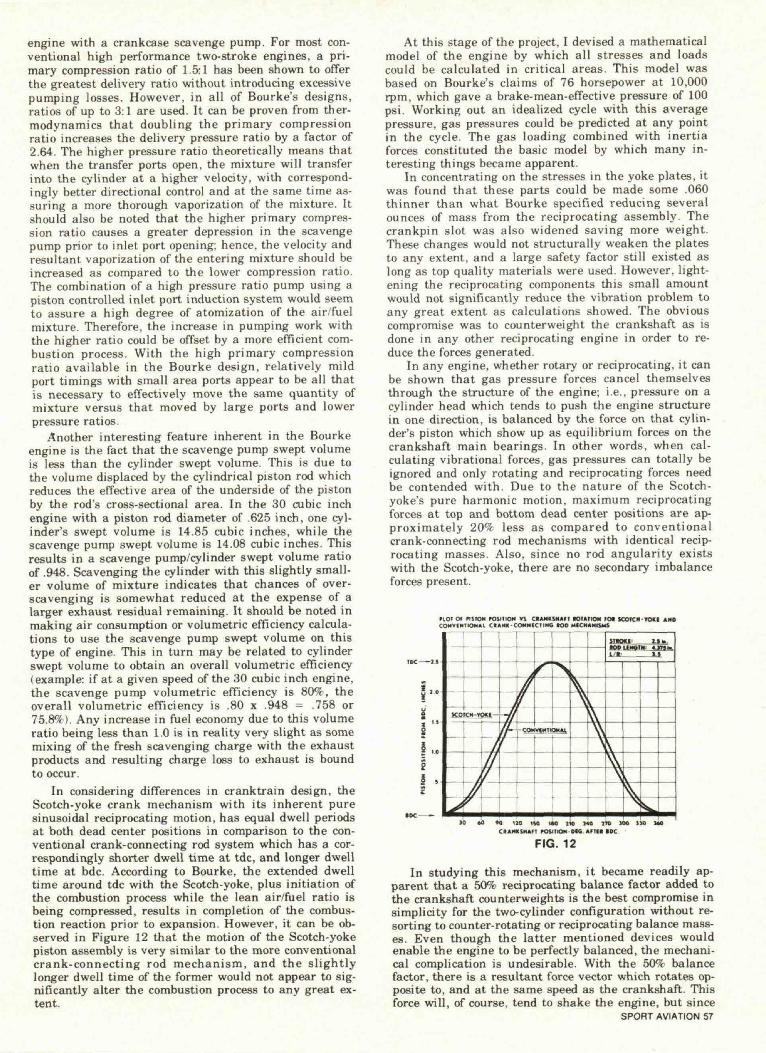
inder pressures were developed through a form of con-trolled preignition of the fuel charge. Moreover, Bourkehimself states that his engines can run with a spark ad-vance of up to 90 degrees before tdc and that theexhaust products are under 200 degrees F. Recent exper-iments into abnormal combustion in two-stroke engineshas shown that preignition of a relatively lean air/fuelmixture almost doubles the combustion pressure at tdcwhile proportionally increasing the work of the compres-sion process. From Figure 11, it can be demonstratedthat the overall mean effective pressure would be in-creased as compared to normal combustion with a pre-dictable increase in the pressure during the compressionprocess.
FIG. 10
FIG. 11
In any spark-ignited internal combustion engine,preignition tends to increase heat loss to the coolant,subject the engine to excessive pressures and increasethe work of the compression stroke. However, theBourke engine, with its inherent lack of connecting rodangularity, is supposedly able to withstand these highpressures. Controlled preignition in this engine wouldseem to be of greatest benefit in stopping and reversingthe reciprocating mass at high speeds, primarily by gaspressure alone. This would greatly relieve the loads im-posed on the crankshaft and reduce tensile stresses inthe reciprocating parts.
Considering the mechanical aspects of this engine, avery interesting attribute of the Bourke design is thathigh primary compression ratios are obtainable due tothe mechanical configuration. Since the scavenge pumpcomprises only the swept volume of the cylinder beneaththe piston, the free volume that exists may be consider-ably reduced as compared to the conventional two-stroke
engine with a crankcase scavenge pump. For most con-ventional high performance two-stroke engines, a pri-mary compression ratio of 1.5:1 has been shown to offerthe greatest delivery ratio without introducing excessivepumping losses. However, in all of Bourke's designs,ratios of up to 3:1 are used. It can be proven from ther-modynamics that doubling the primary compressionratio increases the delivery pressure ratio by a factor of2.64. The higher pressure ratio theoretically means thatwhen the transfer ports open, the mixture will transferinto the cylinder at a higher velocity, with correspond-ingly better directional control and at the same time as-suring a more thorough vaporization of the mixture. Itshould also be noted that the higher primary compres-sion ratio causes a greater depression in the scavengepump prior to inlet port opening; hence, the velocity andresultant vaporization of the entering mixture should beincreased as compared to the lower compression ratio.The combination of a high pressure ratio pump using apiston controlled inlet port induction system would seemto assure a high degree of atomization of the air/fuelmixture. Therefore, the increase in pumping work withthe higher ratio could be offset by a more efficient com-bustion process. With the high primary compressionratio available in the Bourke design, relatively mildport timings with small area ports appear to be all thatis necessary to effectively move the same quantity ofmixture versus that moved by large ports and lowerpressure ratios.
Another interesting feature inherent in the Bourkeengine is the fact that the scavenge pump swept volumeis less than the cylinder swept volume. This is due tothe volume displaced by the cylindrical piston rod whichreduces the efTective area of the underside of the pistonby the rod's cross-sectional area. In the 30 cubic inchengine with a piston rod diameter of .625 inch, one cyl-inder's swept volume is 14.85 cubic inches, while thescavenge pump swept volume is 14.08 cubic inches. Thisresults in a scavenge pump/cylinder swept volume ratioof .948. Scavenging the cylinder with this slightly small-er volume of mixture indicates that chances of over-scavenging is somewhat reduced at the expense of alarger exhaust residual remaining. It should be noted inmaking air consumption or volumetric efficiency calcula-tions to use the scavenge pump swept volume on thistype of engine. This in turn may be related to cylinderswept volume to obtain an overall volumetric efficiency(example: if at a given speed of the 30 cubic inch engine,the scavenge pump volumetric efficiency is 80%, theoverall volumetric efficiency is .80 x .948 = .758 or75.8%). Any increase in fuel economy due to this volumeratio being less than 1.0 is in reality very slight as somemixing of the fresh scavenging charge with the exhaustproducts and resulting charge loss to exhaust is boundto occur.
In considering differences in cranktrain design, theScotch-yoke crank mechanism with its inherent puresinusoidal reciprocating motion, has equal dwell periodsat both dead center positions in comparison to the con-ventional crank-connecting rod system which has a cor-respondingly shorter dwell time at tdc, and longer dwelltime at bdc. According to Bourke, the extended dwelltime around tdc with the Scotch-yoke, plus initiation ofthe combustion process while the lean air/fuel ratio isbeing compressed, results in completion of the combus-tion reaction prior to expansion. However, it can be ob-served in Figure 12 that the motion of the Scotch-yokepiston assembly is very similar to the more conventionalcrank-connecting rod mechanism, and the slightlylonger dwell time of the former would not appear to sig-nificantly alter the combustion process to any great ex-tent.
At this stage of the project, I devised a mathematicalmodel of the engine by which all stresses and loadscould be calculated in critical areas. This model wasbased on Bourke's claims of 76 horsepower at 10,000rpm, which gave a brake-mean-effective pressure of 100psi. Working out an idealized cycle with this averagepressure, gas pressures could be predicted at any pointin the cycle. The gas loading combined with inertiaforces constituted the basic model by which many in-teresting things became apparent.
In concentrating on the stresses in the yoke plates, itwas found that these parts could be made some .060thinner than what Bourke specified reducing severalounces of mass from the reciprocating assembly. Thecrankpin slot was also widened saving more weight.These changes would not structurally weaken the platesto any extent, and a large safety factor still existed aslong as top quality materials were used. However, light-ening the reciprocating components this small amountwould not significantly reduce the vibration problem toany great extent as calculations showed. The obviouscompromise was to counterweight the crankshaft as isdone in any other reciprocating engine in order to re-duce the forces generated.
In any engine, whether rotary or reciprocating, it canbe shown that gas pressure forces cancel themselvesthrough the structure of the engine; i.e., pressure on acylinder head which tends to push the engine structurein one direction, is balanced by the force on that cylin-der's piston which show up as equilibrium forces on thecrankshaft main bearings. In other words, when cal-culating vibrational forces, gas pressures can totally beignored and only rotating and reciprocating forces needbe contended with. Due to the nature of the Scotch-yoke's pure harmonic motion, maximum reciprocatingforces at top and bottom dead center positions are ap-proximately 20% less as compared to conventionalcrank-connecting rod mechanisms with identical recip-rocating masses. Also, since no rod angularity existswith the Scotch-yoke, there are no secondary imbalanceforces present.
PlOf Of PISTON POSITION VS CiANKSMAfT lOTATtOM fOt SCOKN-VOKI ANDCOMVINTIONAl CIAMK-COMMIC1ING M>» MfCHANISMS
2O 1)0 IftO 210 240 270 500 >»CP.ANKSNAfT POSITION-DfC Afllt tOC
FIG. 12
In studying this mechanism, it became readily ap-parent that a 50% reciprocating balance factor added tothe crankshaft counterweights is the best compromise insimplicity for the two-cylinder configuration without re-sorting to counter-rotating or reciprocating balance mass-es. Even though the latter mentioned devices wouldenable the engine to be perfectly balanced, the mechani-cal complication is undesirable. With the 50% balancefactor, there is a resultant force vector which rotates op-posite to, and at the same speed as the crankshaft. Thisforce will, of course, tend to shake the engine, but since
SPORT AVIATION 57

it is exactly half the magnitude of the unbalanced case,and since it is a rotating force, it is much easier to con-tend with as far as mounting systems, etc., are con-cerned.
With regard to the crankshaft, the increase in mainbearing diameter to 1.377 inches, as Vaux had specified,was thought beneficial . It seems that the originalBourke 30 would occasionally break its 1.181 diametershaft under certain conditions, as I learned from talkingto some of Russ Bourke's acquaintances. It was alsostated in Bourke's writings that propeller hub bolts,driveshaft keys, etc., could be sheared at will simply byopening the throttle too rapidly. Again relying on themathematical model, I determined the forces applied onthe crankpin from the reciprocating components andplotted a moment diagram for 180 degrees of crankshaftrotation (or one stroke) at speeds ranging from 3000 to10,000 rpm. The results are shown in Figure 13. At agiven rpm, say 8000, it will be noted that from 0 toabout 85 degrees, the torque becomes positive indicatingthe shaft is now exerting this torque on the load. Notethat the torque peaks are always of a higher value onthe positive side indicating that the average torque overthe 180 degree interval is positive, as would be neces-sary for the engine to produce power (the same valuesare obtained during the next 180 degrees of rotation, soone needs only to study the first 180 degree interval).Since these values are hypothetical, the actual values ona real running engine would be somewhat less. Thisdoes, however, indicate the high-magnitude second-ordertorque fluctuations which caused shaft and drive systembreakage. The obvious remedy is to add rotational iner-tia to the crankshaft in the form of a flywheel, some-thing Bourke, for rather obscure reasons, always seemedto avoid.
The Vaux crankshaft was adequately sized forstrength, but with only one counter-balance weight, itwas not considered suitable for reasons previously men-tioned. It was apparent that a new crankshaft should bemade to compliment the lightened rod-yoke assemblyand allow desirable counterbalance masses to be locatedon both sides of the crankpin. I then designed acrankshaft utilizing the larger main bearings of theVaux shaft with removable counterweights similar tothat used on the original Bourke crankshaft.
During this time I graduated from Vanderbilt with aBachelors degree in mechanical engineering and went towork for a major engine manufacturer. Being somewhatdisappointed that I was not able to complete the Bourkeengine evaluation while in college, I continued to workon the engine in my spare time at home.
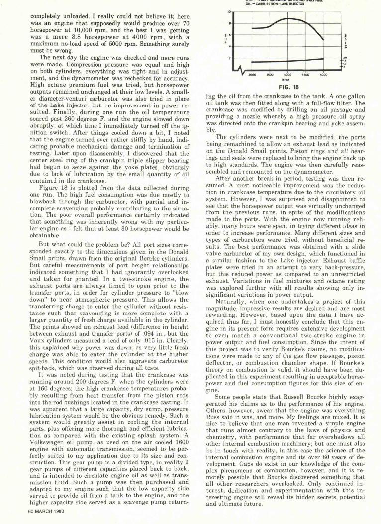
My next step was to complete the drawings of thecrankshaft and rod-yoke assembly and submit them to amachine shop. The first parts to be made comprised therod-yoke assembly. Both rods and yoke plates were to bemade of billet and flat stock 4140 alloy steel, hardenedand drawn to Rockwell C-35. The piston rods wererifle-drilled for lightness and had a ground finish allover as did the yoke plates. Figure 14 shows these com-ponents prior to assembly. A crankshaft was next to bebuilt and this too was made from 4140 steel, turnedfrom billet stock, and heat treated to a hardness ofRockwell C-38. A new crankpin bearing was also made,the inner and outer rings consisting of Ampco 22 bronzealloy, which has a yield strength of 62,000 psi, slightlysuperior to Ampco 18-22 alloy, which Bourke recom-mended for this part of the engine. A hardened andground alloy steel ring was made to serve as the inter-mediate bearing between the bronze rings, and thiscompleted the triple-slipper bearing assembly. Figures15 and 16 show the bearing, crankshaft, and counter-weights in the disassembled and assembled states. At58 MARCH 1980
15 JO 45 «0 75 90 108 120 136 MO M MOe.Dcwccs FROM BDC CYU*I.
FIG. 13
FIG. 14
this time, a number of other items were remade to bringall components up to the highest standard of precision.The crankcase faces were checked and resurfaced to en-sure that all mounting surfaces would be square, andthe piston rod bores were machined larger for bronze rodbushings, which were then turned and pressed intoplace.
I now possessed all the parts, made to my specifica-tions, which would give a highly precision engine withwhich an accurate evaluation could now be performed. Icarefully assembled the engine on a meticulouslycleaned work bench, with all parts fitting together likethe proverbial "Swiss watch." An electric starter from asnowmobile engine was now fitted and again, initialrunning was performed in my backyard under a no-loadcondition. The engine started on the first attempt andran better than it ever had previously. Vibration levelswere greatly reduced by the 50% balance factor, and theengine appeared to shake no more than a conventional
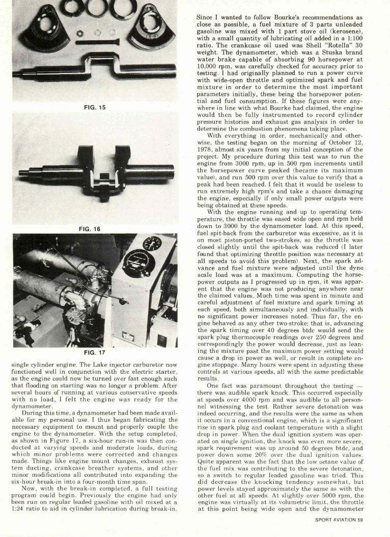
FIG. 15
FIG. 16
FIG. 17
single cylinder engine. The Lake injector carburetor nowfunctioned well in conjunction with the electric starter,as the engine could now be turned over fast enough suchthat flooding on starting was no longer a problem. Afterseveral hours of running at various conservative speedswith no load, I felt the engine was ready for thedynamometer.
During this time, a dynamometer had been made avail-able for my personal use. I thus began fabricating thenecessary equipment to mount and properly couple theengine to the dynamometer. With the setup completed,as shown in Figure 17, a six-hour run-in was then con-ducted at varying speeds and moderate loads, dur ingwhich minor problems were corrected and changesmade. Things like engine mount changes, exhaust sys-tem duct ing, crankcase breather systems, and otherminor modifications all contributed into expanding thesix-hour break-in into a four-month time span.
Now, with the break-in completed, a f u l l testingprogram could begin. Previously the engine had onlybeen run on regular leaded gasoline with oil mixed at a1:24 ratio to aid in cylinder lubrication during break-in.
Since I wanted to follow Bourke's recommendations asclose as possible, a fuel mixture of 3 parts unleadedgasoline was mixed with 1 part stove oil (kerosene),with a small quantity of lubricating oil added in a 1:100ratio. The crankcase oil used was Shell "Rotella" 30weight. The dynamometer, which was a Stuska brandwater brake capable of absorbing 90 horsepower at10,000 rpm, was carefully checked for accuracy prior totesting. I had originally planned to run a power curvewith wide-open throttle and optimized spark and fuelmixture in order to determine the most importantparameters initially, these being the horsepower poten-tial and fuel consumption. If these figures were any-where in line with what Bourke had claimed, the enginewould then be fully instrumented to record cylinderpressure histories and exhaust gas analysis in order todetermine the combustion phenomena taking place.
With everything in order, mechanically and other-wise, the testing began on the morning of October 12,1978, almost six years from my initial conception of theproject. My procedure during this test was to run theengine from 3000 rpm, up in 500 rpm increments untilthe horsepower curve peaked (became its maximumvalue), and run 500 rpm over this value to verify that apeak had been reached. I felt that it would be useless torun extremely high rpm's and take a chance damagingthe engine, especially if only small power outputs werebeing obtained at these speeds.
With the engine running and up to operating tem-perature, the throttle was eased wide open and rpm helddown to 3000 by the dynamometer load. At this speed,fuel spit-back from the carburetor was excessive, as it ison most piston-ported two-strokes, so the throttle wasclosed slightly until the spit-back was reduced (I laterfound that optimizing throttle position was necessary atall speeds to avoid this problem). Next, the spark ad-vance and fuel mixture were adjusted unti l the dynoscale load was at a maximum. Computing the horse-power outputs as I progressed up in rpm, it was appar-ent that the engine was not producing anywhere nearthe claimed values. Much time was spent in minute andcareful adjustment of fuel mixture and spark timing ateach speed, both simultaneously and individually, withno significant power increases noted. Thus far, the en-gine behaved as any other two-stroke; that is, advancingthe spark timing over 40 degrees btdc would send thespark plug thermocouple readings over 250 degrees andcorrespondingly the power would decrease, just as lean-ing the mixture past the maximum power setting wouldcause a drop in power as well, or result in complete en-gine stoppage. Many hours were spent in adjusting thesecontrols at various speeds, all with the same predictableresults.
One fact was paramount throughout the testing —there was audible spark knock. This occurred especiallyat speeds over 4000 rpm and was audible to all person-nel witnessing the test. Rather severe detonation wasindeed occurring, and the results were the same as whenit occurs in a conventional engine, which is a significantrise in spark plug and coolant temperature with a slightdrop in power. When the dual ignition system was oper-ated on single ignition, the knock was even more severe,spark requirement was up around 50 degrees btdc, andpower down some 20'X over the dual ignition values.Quite apparent was the fact that the low octane value ofthe fuel mix was contributing to the severe detonation,so a switch to regular leaded gasoline was tried. Thisdid decrease the knocking tendency somewhat, butpower levels stayed approximately the same as with theother fuel at all speeds. At slightly over 5000 rpm, theengine was virtually at its volumetric limit, the throttleat this point being wide open and the dynamometer
SPORT AVIATION 59
FUEL- 3 PARIS UNLEADED GASOLINE-1 MIT FUELOIL -CA«BURETION-LAKE INJECTOR
completely unloaded. I really could not believe it; herewas an engine that supposedly would produce over 70horsepower at 10,000 rpm, and the best I was gettingwas a mere 8.8 horsepower at 4000 rpm, with amaximum no-load speed of 5000 rpm. Something surelymust be wrong.
The next day the engine was checked and more runswere made. Compression pressure was equal and highon both cylinders, everything was tight and in adjust-ment, and the dynamometer was rechecked for accuracy.High octane premium fuel was tried, but horsepoweroutputs remained unchanged at their low levels. A small-er diameter-venturi carburetor was also tried in placeof the Lake injector, but no improvement in power re-sulted. Finally, during one run the oil temperaturesoared past 260 degrees F. and the engine slowed downabruptly, at which time I immediately turned off the ig-nition switch. After things cooled down a bit, I notedthat the engine turned over rather stiffly by hand, indi-cating probable mechanical damage and termination oftesting. Later upon disassembly, I discovered that thecenter steel ring of the crankpin triple slipper bearinghad begun to seize against the yoke plates, obviouslydue to lack of lubrication by the small quantity of oilcontained in the crankcase.
Figure 18 is plotted from the data collected duringone run. The high fuel consumption was due mostly toblowback through the carburetor, with partial and in-complete scavenging probably contributing to the situa-tion. The poor overall performance certainly indicatedthat something was inherently wrong with my particu-lar engine as I felt that at least 30 horsepower would beobtainable.
But what could the problem be? All port sizes corre-sponded exactly to the dimensions given in the DonaldSmail prints, drawn from the original Bourke cylinders.But careful measurements of port height relationshipsindicated something that I had ignorantly overlookedand taken for granted. In a two-stroke engine, theexhaust ports are always timed to open prior to thetransfer ports, in order for cylinder pressure to "blowdown" to near atmospheric pressure. This allows thetransferring charge to enter the cylinder without resis-tance such that scavenging is more complete with alarger quantity of fresh charge available in the cylinder.The prints showed an exhaust lead (difference in heightbetween exhaust and transfer ports) of .094 in., but theVaux cylinders measured a lead of only .015 in. Clearly,this explained why power was down, as very little freshcharge was able to enter the cylinder at the higherspeeds. This condition would also aggravate carburetorspit-back, which was observed during all tests.
It was noted during testing that the crankcase wasrunning around 200 degrees F. when the cylinders wereat 160 degrees; the high crankcase temperatures proba-bly resulting from heat transfer from the piston rodsinto the rod bushings located in the crankcase casting. Itwas apparent that a large capacity, dry sump, pressurelubrication system would be the obvious remedy. Such asystem would greatly assist in cooling the internalparts, plus offering more thorough and efficient lubrica-tion as compared with the existing splash system. AVolkswagen oil pump, as used on the air cooled 1600engine with automatic transmission, seemed to be per-fectly suited to my application due to its size and con-struction. This gear pump is a divided type, in reality 2gear pumps of different capacities placed back to back,and is intended to circulate engine oil as well as trans-mission fluid. Such a pump was then purchased andadapted to my engine such that the low capacity sideserved to provide oil from a tank to the engine, and thehigher capacity side served as a scavenge pump return-
60 MARCH 1980
FIG. 18ing the oil from the crankcase to the tank. A one gallonoil tank was then fitted along with a full-flow filter. Thecrankcase was modified by drilling an oil passage andproviding a nozzle whereby a high pressure oil spraywas directed onto the crankpin bearing and yoke assem-bly.
The cylinders were next to be modified, the portsbeing remachined to allow an exhaust lead as indicatedon the Donald Smail prints. Piston rings and all bear-ings and seals were replaced to bring the engine back upto high standards. The engine was then carefully reas-sembled and remounted on the dynamometer.
After another break-in period, testing was then re-sumed. A most noticeable improvement was the reduc-tion in crankcase temperature due to the circulatory oilsystem. However, I was surprised and disappointed tosee that the horsepower output was virtually unchangedfrom the previous runs, in spite of the modificationsmade to the ports. With the engine now running reli-ably, many hours were spent in trying different ideas inorder to increase performance. Many different sizes andtypes of carburetors were tried, without beneficial re-sults. The best performance was obtained with a slidevalve carburetor of my own design, which functioned ina similar fashion to the Lake injector. Exhaust baffleplates were tried in an attempt to vary back-pressure,but this reduced power as compared to an unrestrictedexhaust. Variations in fuel mixtures and octane ratingwas explored further with all results showing only in-significant variations in power output.
Naturally, when one undertakes a project of thismagnitude, impressive results are desired and are mostrewarding. However, based upon the data I have ac-quired thus far, I must honestly conclude that this en-gine in its present form requires extensive developmentto even match a conventional two-stroke engine inpower output and fuel consumption. Since the intent ofthis project was to verify Bourke's claims, no modifica-tions were made to any of the gas flow passages, pistondeflector, or combustion chamber shape. If Bourke'stheory on combustion is valid, it should have been du-plicated in this experiment resulting in acceptable horse-power and fuel consumption figures for this size of en-gine.
Some people state that Russell Bourke highly exag-gerated his claims as to the performance of his engine.Others, however, swear that the engine was everythingRuss said it was, and more. My feelings are mixed. It isnice to believe that one man invented a simple enginethat runs almost contrary to the laws of physics andchemistry, with performance that far overshadows allother internal combustion machinery; but one must alsobe in touch with reality, in this case the science of theinternal combustion engine and its over 80 years of de-velopment. Gaps do exist in our knowledge of the com-plex phenomena of combustion, however, and it is re-motely possible that Bourke discovered something thatall other researchers overlooked. Only continued in-terest, dedication and experimentation with this in-teresting engine will reveal its hidden secrets, potentialand ultimate future.