PERFORMANCE SPECIFICATION - NSTXL
55
PRF-PT-00425 Rev 1 N61339-01-D-0717/0003 6 Feb 2006 PERFORMANCE SPECIFICATION FOR THE INDEPENDENT TARGET SYSTEM (ITS) KIT FOR THE MULTIPLE INTEGRATED LASER ENGAGEMENT SYSTEM (MILES) TRAINING SYSTEM Prepared by: U.S. Army Program Executive Office Simulation, Training, and Instrumentation (PEO STRI) 12350 Research Parkway Orlando, FL 32826-3276 DISTRIBUTION LIST STATEMENT A: Approved for public release; distribution is unlimited.
Transcript of PERFORMANCE SPECIFICATION - NSTXL
PRF-PT-00425 Rev 1
N61339-01-D-0717/0003
6 Feb 2006
PERFORMANCE SPECIFICATION
FOR THE
INDEPENDENT TARGET SYSTEM (ITS) KIT
FOR THE
MULTIPLE INTEGRATED LASER ENGAGEMENT SYSTEM (MILES) TRAINING SYSTEM
Prepared by:
U.S. Army Program Executive Office Simulation, Training, and Instrumentation (PEO STRI)
12350 Research Parkway Orlando, FL 32826-3276
DISTRIBUTION LIST STATEMENT A: Approved for public release; distribution is
unlimited.
PRF-PT-00425 Rev 1
N61339-01-D-0717/0003
6 Feb 2006
i
TABLE OF CONTENTS
1 SCOPE ---------------------------------------------------------------------------------------- 1
1.1. SYSTEM DESCRIPTION ----------------------------------------------------------------------------------------- 1
1.2. BACKGROUND --------------------------------------------------------------------------------------------------- 1
2 APPLICABLE DOCUMENTS ----------------------------------------------------------- 1
2.1. SPECIFICATIONS, STANDARDS AND HANDBOOKS ---------------------------------------------------------- 1
2.2. OTHER GOVERNMENT DOCUMENTS -------------------------------------------------------------------------- 2
2.3. CODE OF FEDERAL REGULATIONS --------------------------------------------------------------------------- 2
2.4. NON-GOVERNMENT STANDARDS AND PUBLICATIONS --------------------------------------------------- 3
2.5. ORDER OF PRECEDENCE -------------------------------------------------------------------------------------- 3
3 REQUIREMENTS -------------------------------------------------------------------------- 3
3.1. DEFINITION ------------------------------------------------------------------------------------------------------- 3
3.2. ITS INTERFACES --------------------------------------------------------------------------------------------- 3 3.2.1 MILES Interfaces -------------------------------------------------------------------------------------------------------------- 4 3.2.2 Data Transfer Interfaces ------------------------------------------------------------------------------------------------------ 4 3.2.3 Direct/Indirect Fire Cue (DIFCUE) Interface ----------------------------------------------------------------------------- 4 3.2.4 MCTC IS Interface ------------------------------------------------------------------------------------------------------------- 4
3.3. SYSTEM PERFORMANCE --------------------------------------------------------------------------------------- 4 3.3.1 General Requirements --------------------------------------------------------------------------------------------------------- 5
3.3.1.1 Decoding Messages ---------------------------------------------------------------------------------------------------------------------- 5 3.3.1.2 Compatibility ------------------------------------------------------------------------------------------------------------------------------ 5 3.3.1.3 Externally Programmable. --------------------------------------------------------------------------------------------------------------- 6 3.3.1.4 Assess Effects ----------------------------------------------------------------------------------------------------------------------------- 6 3.3.1.5 Audio/Visual Signals -------------------------------------------------------------------------------------------------------------------- 6 3.3.1.6 PID Processing---------------------------------------------------------------------------------------------------------------------------- 6 3.3.1.7 Internal Clock ----------------------------------------------------------------------------------------------------------------------------- 6 3.3.1.8 MILES Events ---------------------------------------------------------------------------------------------------------------------------- 6
3.3.1.8.1 Initiation events -------------------------------------------------------------------------------------------------------------------- 7 3.3.1.8.2 Lethality assessment events ------------------------------------------------------------------------------------------------------- 7 3.3.1.8.3 Cheat Events ------------------------------------------------------------------------------------------------------------------------ 7 3.3.1.8.4 Administrative events -------------------------------------------------------------------------------------------------------------- 7
3.3.1.9 Casualties ---------------------------------------------------------------------------------------------------------------------------------- 8 3.3.1.10 Recall ------------------------------------------------------------------------------------------------------------------------------------- 8 3.3.1.11 Selection of Vehicle Type ------------------------------------------------------------------------------------------------------------- 8 3.3.1.12 Download Capability ------------------------------------------------------------------------------------------------------------------- 8 3.3.1.13 Low Power Indicator ------------------------------------------------------------------------------------------------------------------- 8 3.3.1.14 Cheat Indication ------------------------------------------------------------------------------------------------------------------------- 8 3.3.1.15 Resurrection command ----------------------------------------------------------------------------------------------------------------- 9 3.3.1.16 Memory Clear Function ---------------------------------------------------------------------------------------------------------------- 9 3.3.1.17 Catastrophic Kill ------------------------------------------------------------------------------------------------------------------------ 9
3.3.2 Specific Requirements --------------------------------------------------------------------------------------------------------- 9 3.3.3 BIT Characteristics ---------------------------------------------------------------------------------------------------------- 11 3.3.4 Computational System Requirements ------------------------------------------------------------------------------------- 11
3.3.4.1 Operational Computer Systems ------------------------------------------------------------------------------------------------------- 11 3.3.4.2 Operational System Software --------------------------------------------------------------------------------------------------------- 12
3.3.4.2.1 Software Development Requirements ----------------------------------------------------------------------------------------- 12 3.3.4.2.2 Run Time Environment --------------------------------------------------------------------------------------------------------- 12 3.3.4.2.3 Firmware -------------------------------------------------------------------------------------------------------------------------- 12
3.3.5 False Alarm Rate ------------------------------------------------------------------------------------------------------------ 12
PRF-PT-00425 Rev 1
N61339-01-D-0717/0003
6 Feb 2006
ii
3.3.6 Installation and Removal Requirements ---------------------------------------------------------------------------------- 12 3.3.6.1 Mounting Devices ---------------------------------------------------------------------------------------------------------------------- 12 3.3.6.2 Interfacing Cabling --------------------------------------------------------------------------------------------------------------------- 13
3.3.7 Transit Cases ----------------------------------------------------------------------------------------------------------------- 13
3.4. POWER ---------------------------------------------------------------------------------------------------------- 13 3.4.1 Power Control ---------------------------------------------------------------------------------------------------------------- 13 3.4.2 Power Operation ------------------------------------------------------------------------------------------------------------- 14 3.4.3 Batteries ----------------------------------------------------------------------------------------------------------------------- 14 3.4.4 Reliability --------------------------------------------------------------------------------------------------------------------- 14 3.4.5 Maintainability --------------------------------------------------------------------------------------------------------------- 14
3.5. PHYSICAL CHARACTERISTICS ------------------------------------------------------------------------------- 14 3.5.1 Weight ------------------------------------------------------------------------------------------------------------------------- 14 3.5.2 Size ----------------------------------------------------------------------------------------------------------------------------- 15 3.5.3 Finish -------------------------------------------------------------------------------------------------------------------------- 15 3.5.4 Color --------------------------------------------------------------------------------------------------------------------------- 15 3.5.5 Transportability -------------------------------------------------------------------------------------------------------------- 15
3.6. ENVIRONMENTAL CONDITIONS ------------------------------------------------------------------------------ 15 3.6.1 High Temperature ----------------------------------------------------------------------------------------------------------- 15 3.6.2 Low Temperature ------------------------------------------------------------------------------------------------------------ 16 3.6.3 Shock -------------------------------------------------------------------------------------------------------------------------- 16 3.6.4 Vibration ---------------------------------------------------------------------------------------------------------------------- 16 3.6.5 Humidity ---------------------------------------------------------------------------------------------------------------------- 16 3.6.6 Rain ---------------------------------------------------------------------------------------------------------------------------- 16 3.6.7 Sand and Dust ---------------------------------------------------------------------------------------------------------------- 16 3.6.8 Immersion --------------------------------------------------------------------------------------------------------------------- 17 3.6.9 Corrosion --------------------------------------------------------------------------------------------------------------------- 17 3.6.10 Salt and Fog----------------------------------------------------------------------------------------------------------------- 17
3.7. CONSTRUCTION ----------------------------------------------------------------------------------------------- 17 3.7.1 electromagnetic radiation. -------------------------------------------------------------------------------------------------- 17
3.7.1.1 Conducted Susceptibility -------------------------------------------------------------------------------------------------------------- 17 3.7.1.2 Radiated Emissions -------------------------------------------------------------------------------------------------------------------- 18 3.7.1.3 Conducted Emissions ------------------------------------------------------------------------------------------------------------------ 18 3.7.1.4 Radiated Susceptibility ---------------------------------------------------------------------------------------------------------------- 18
3.7.2 Material and Parts ----------------------------------------------------------------------------------------------------------- 18 3.7.3 Nameplates and product marking ----------------------------------------------------------------------------------------- 18 3.7.4 Interchangeability ----------------------------------------------------------------------------------------------------------- 18 3.7.5 System Safety ----------------------------------------------------------------------------------------------------------------- 19
3.7.5.1 Electrical Safety ------------------------------------------------------------------------------------------------------------------------ 19 3.7.5.2 Hazardous Materials ------------------------------------------------------------------------------------------------------------------- 19 3.7.5.3 Mechanical Safety ---------------------------------------------------------------------------------------------------------------------- 19 3.7.5.4 Personnel Safety ------------------------------------------------------------------------------------------------------------------------ 19 3.7.5.5 Ionizing Radiation ---------------------------------------------------------------------------------------------------------------------- 20 3.7.5.6 Laser Safety ----------------------------------------------------------------------------------------------------------------------------- 20 3.7.5.7 Radioactive Material Restriction in Optical Products ----------------------------------------------------------------------------- 20
3.7.6 Human engineering ---------------------------------------------------------------------------------------------------------- 20
3.8. FIRST ARTICLE INSPECTION --------------------------------------------------------------------------------- 21
4 VERIFICATION ---------------------------------------------------------------------------- 21
4.1. DESIGN VERIFICATION ---------------------------------------------------------------------------------------- 21
4.2. VERIFICATION METHODS ------------------------------------------------------------------------------ 24
4.3. INTEGRATION TESTS ------------------------------------------------------------------------------------------ 24
4.4. SYSTEM VERIFICATION TESTS (SVT)---------------------------------------------------------------------- 24
4.5. SYSTEM INTEGRATION TESTS (SIT) ----------------------------------------------------------------------- 24
PRF-PT-00425 Rev 1
N61339-01-D-0717/0003
6 Feb 2006
iii
4.5.1 Operational System Software ----------------------------------------------------------------------------------------------- 24 4.5.1.1 Software Development Requirements ----------------------------------------------------------------------------------------------- 25 4.5.1.2 Firmware --------------------------------------------------------------------------------------------------------------------------------- 25
4.5.2 Transit Cases ----------------------------------------------------------------------------------------------------------------- 25 4.5.3 Transportability -------------------------------------------------------------------------------------------------------------- 25 4.5.4 Reliability --------------------------------------------------------------------------------------------------------------------- 25 4.5.5 Maintainability --------------------------------------------------------------------------------------------------------------- 25 4.5.6 Environmental Conditions -------------------------------------------------------------------------------------------------- 25
4.5.6.1 High Temperature ---------------------------------------------------------------------------------------------------------------------- 26 4.5.6.2 Low Temperature ----------------------------------------------------------------------------------------------------------------------- 27 4.5.6.3 Shock ------------------------------------------------------------------------------------------------------------------------------------- 28 4.5.6.4 Vibration --------------------------------------------------------------------------------------------------------------------------------- 28 4.5.6.5 Humidity --------------------------------------------------------------------------------------------------------------------------------- 29 4.5.6.6 Rain--------------------------------------------------------------------------------------------------------------------------------------- 29 4.5.6.7 Sand and Dust --------------------------------------------------------------------------------------------------------------------------- 30 4.5.6.8 Immersion (Leakage) ------------------------------------------------------------------------------------------------------------------ 30 4.5.6.9 Corrosion -------------------------------------------------------------------------------------------------------------------------------- 31 4.5.6.10 Salt and Fog --------------------------------------------------------------------------------------------------------------------------- 31
4.5.7 Electromagnetic Radiation ------------------------------------------------------------------------------------------------- 31 4.5.7.1 Conducted Susceptibility -------------------------------------------------------------------------------------------------------------- 31 4.5.7.2 Radiated Emissions -------------------------------------------------------------------------------------------------------------------- 32 4.5.7.3 Conducted Emissions ------------------------------------------------------------------------------------------------------------------ 32 4.5.7.4 Radiated Susceptibility ---------------------------------------------------------------------------------------------------------------- 32
4.5.8 Interchangeability ----------------------------------------------------------------------------------------------------------- 32 4.5.9 System Safety ----------------------------------------------------------------------------------------------------------------- 32
4.5.9.1 Electrical Safety ------------------------------------------------------------------------------------------------------------------------ 32 4.5.9.2 Hazardous Materials ------------------------------------------------------------------------------------------------------------------- 33 4.5.9.3 Mechanical Safety ---------------------------------------------------------------------------------------------------------------------- 33 4.5.9.4 Personnel Safety ------------------------------------------------------------------------------------------------------------------------ 33 4.5.9.5 Ionizing Radiation ---------------------------------------------------------------------------------------------------------------------- 33 4.5.9.6 Laser Safety ----------------------------------------------------------------------------------------------------------------------------- 34 4.5.9.7 Radioactive Material Restrictions in Optical Products ---------------------------------------------------------------------------- 34
4.5.10 Target Visual Kill Status Observation ----------------------------------------------------------------------------------- 34 4.5.11 Power Operation ----------------------------------------------------------------------------------------------------------- 34
4.6. FIRST ARTICLE INSPECTION --------------------------------------------------------------------------------- 34
5 PACKAGING ------------------------------------------------------------------------------- 35
6 NOTES --------------------------------------------------------------------------------------- 35
6.1. ADAPTABILITY ------------------------------------------------------------------------------------------------- 35 6.1.1 Abbreviations and Acronyms ----------------------------------------------------------------------------------------------- 35
APPENDIX A-----------------------------------------------------------------------------------A-1
APPENDIX B-----------------------------------------------------------------------------------B-1
APPENDIX C-----------------------------------------------------------------------------------C-1
APPENDIX D-----------------------------------------------------------------------------------D-1
APPENDIX E-----------------------------------------------------------------------------------E-1
PRF-PT-00425 Rev 1
N61339-01-D-0717/0003
6 Feb 2006
1
1 SCOPE
This performance specification defines the performance requirements of the Independent Target System (ITS) Kit for the Multiple Integrated Laser Engagement System (MILES) Training System.
1.1. SYSTEM DESCRIPTION
The ITS kit will be compatible with the MILES XXI equipment and devices and downwardly operational compatible with the Basic MILES and MILES 2000 training devices. The MILES XXI system will be fielded worldwide and used in all geographical areas. The ITS Kit shall be fielded concurrently with the MILES XXI system. The ITS will not require any new manpower assets, personnel requirements, or qualifications.
1.2. BACKGROUND
The family of the Basic MILES was developed in the early 1980’s using technology and designs then available. The Army has identified the need for enhanced force-on-force simulation of armor and anti-armor devices. The enhancements will include player identification (PID), fratricide identification, multiple levels of kill, and vulnerability due to direction of attack. New weapons, ammunition, and weapon performance will be accommodated. The MILES XXI requirement is for the replacement of the existing U.S. army direct fire ground based MILES devices (Basic MILES) with the laser-based Tactical Engagement Simulation (TES) training devices.
2 APPLICABLE DOCUMENTS
The following documents shown below form a part of this Specification to the extent specified herein.
2.1. SPECIFICATIONS, STANDARDS AND HANDBOOKS
The following specifications, standards, and handbooks form a part of this document to the extent specified herein.
MILITARY STANDARDS
MIL-STD-810E Notice 3 Environmental Test Methods and Engineering Guidelines
MIL-STD-1553B Notice 4 Digital Time Division Command/Response Multiplex Data Bus
MIL-STD-1472F Human Engineering Design Criteria for Military Systems, Equipment and Facilities
(Unless otherwise indicated, copies of the above specifications, standards, and handbook are available through: http://astimage.daps.dla.mil/quicksearch/.

PRF-PT-00425 Rev 1
N61339-01-D-0717/0003
6 Feb 2006
2
2.2. OTHER GOVERNMENT DOCUMENTS
The following other Government documents, drawings, and publications form a part of this specification to the extent specified herein.
PRF-PT-0057 MILES XXI Performance Specification (26 Mar 2002)
Mil-Std-461E DoD Interface Standard, Requirements for the Control of EMI Characteristics of Subsystems and Equipment
PMT 90-S002J MILES Communication Code (MCC)
19207-12465074H M2A3/M3A3 Interface Control Document for External Training Devices
9721802D Prime Item Function Specification for the Keyless Main Gun Signature Simulator (MGSS)
9721801C Prime Item Function Specification for the Keyless Direct/Indirect Fire Cue (DIFCUE)
ICD 706014-E.1 Interface Control Document for the SAWE/MILES II
ICD 3110-(001-013) MILES 2000 Interface Control Document
MILXXI-TS-0005 MILES XXI Interface Control Document
290065 RDMS DCIU/TESS for NTC IS
(Unless otherwise specified copies of other Government documents, drawings and publications are available from: http://www.stricom.army.mil/PRODUCTS/MILES_XXI/ )
2.3. CODE OF FEDERAL REGULATIONS
The following code of federal regulations form a part of this document to the extent specified herein.
10 CFR 40 Domestic Licensing of Source Material
21 CFR 40 Performance Standards for Light-Emitting Products
29 CFR 1910 OCCUPATIONAL SAFETY AND HEALTH STANDARDS
(Unless otherwise specified copies of code federal regulations are available from:

PRF-PT-00425 Rev 1
N61339-01-D-0717/0003
6 Feb 2006
3
http://www.access.gpo.gov/nara/cfr/cfr-table-search.html)
2.4. NON-GOVERNMENT STANDARDS AND PUBLICATIONS
The following documents form a part of this document to the extent specified herein.
American National Standards Institute (ANSI)
ANSI/NFPA 70-02 National Electrical Code
Air Transport Association of America, ATA SPEC 300
Packaging of Airline Supplies (Revision 18)
ANSI Z136.1-2000 Safe Use of Laser (Revision of ANSI Z136.1-1993)
ANSI Z136.6-2000 Safe Use of Lasers in an Outdoor Environment
ANSI/NEMA Z535.3 Criteria for Safety Symbols
ANSI/NEMA Z535.4 Product Safety Sign and Labels
(Unless otherwise specified copies of above documents are available from: http://www.nssn.org/search.html)
2.5. ORDER OF PRECEDENCE
In the event of a conflict between the text of this document and the references cited herein, the text of this document takes precedence. Nothing in this document, however, supercedes applicable laws and regulations unless a specific exemption has been obtained.
3 REQUIREMENTS
3.1. DEFINITION
The Independent Target System (ITS) must be compatible and interface with the MILES XXI system, Basic MILES, MILES 2000, and the Army’s Maneuver Combat Training Center’s (MCTC) instrumentation system (IS). These existing Systems are described in the performance specification and Interface Control Documents (ICD) listed in section 2.0.
3.2. ITS INTERFACES
The ITS shall interface optically, electronically, and mechanically with host vehicles systems, weapons systems, and operators. The ITS shall be appended to vehicle systems, weapon systems, individual operators, and other structures such as bunkers, bridges, and buildings. There is an objective that the ITS shall interface with linked weapons using the various MILES instrumentation.

PRF-PT-00425 Rev 1
N61339-01-D-0717/0003
6 Feb 2006
4
3.2.1 MILES INTERFACES
The ITS shall work with the MILES systems to be used as a target with the other devices. The ITS shall interface and communicate with the MILES Systems by way of a laser light beam communication channel through the atmosphere IAW PMT 90-S002J. This includes decoding and interpreting messages.
3.2.2 DATA TRANSFER INTERFACES
The ITS shall provide an external data input/output (I/O) interface via an industry standard interface protocol to meet the specific timing requirements. The data transfer interface shall
allow for the download of event data from the ITS systems, the upload of PID, weapon characteristics, and vulnerability data and the download of events data to a PC, laptop computer, Personal Digital Assistant (PDA), or similar device.
3.2.3 DIRECT/INDIRECT FIRE CUE (DIFCUE) INTERFACE
The ITS shall interface with the DIFCUE, Device number 06-69.The ITS shall provide a signal to trigger the DIFCUE when a catastrophic kill has been assessed.The ITS operation, with the exception of the DIFCUE not firing, shall not be affected when the DIFCUE system is not connected.
3.2.4 MCTC IS INTERFACE
The ITS shall interface electronically with the various Maneuver Combat Training Center’s (MCTC) instrumentation systems.The interface for communications with the JRTC IS and CMTC IS is defined by the Interface Control Document (ICD) for the SAWE/MILES II (ICD 706014-E.1). The interface for communications with the NTC IS is defined by the ICD for the RCS RDMS DCIU/TESS for NTC IS (290065).
3.3. SYSTEM PERFORMANCE
The ITS shall be used during force-on-force and force-on-target engagement simulations to
ITS Kits
MCTC IS MILES XXI, MILES 2000 and Basic MILES Interfaces
Figure 1. ITS Interfaces.
DIFCUE
Data Transfer Interfaces

PRF-PT-00425 Rev 1
N61339-01-D-0717/0003
6 Feb 2006
5
obtain feedback on the effects of direct fire weapon engagement simulations on personnel, independent targets, crew served weapons, and combat vehicles.The ITS shall be able to be used during periods of reduced visibility and darkness. The casualty assessments shall pair attackers and their targets. The engagement results shall be indicated to the target and attacker using visual and audible cues.
3.3.1 GENERAL REQUIREMENTS
The ITS shall handle transmitted and received messages IAW PMT 90-S002J.
3.3.1.1 DECODING MESSAGES
The following Laser Transmitter Unit messages shall be decoded:
(1) Weapon Type
(2) Ammo Type
(3) PID
3.3.1.2 COMPATIBILITY
The ITS shall be compatible with Laser Transmitter codes fired from MILES systems and shall:
a. Detect the encoded laser beam transmitted by the MILES XXI Laser Transmitter in ambient illumination ranging from darkness to full sunlight.
b. Utilize detectors with maximum response centered in the 904.5±25 nanometers range.
c. Pair throughout 360 degrees of detection coverage in azimuth and ±45 degrees of detection coverage in elevation off the centerline of the target.
d. Create a statistical shot pattern that meets the following requirements: The statistical hit profile for the front, back, and sides of the ITS shall consist of a collection of aim points that pair the MILES armor kill words and PID from the 120mm, 25mm, vehicle TOW, dismounted TOW and the AT4 with the ITS. The profile dimensions when measured at the midpoint of the Weapon’s effective range shall attempt to replicate the actual shape of the vehicle. The profile shall be larger than a circle with a diameter of one meter and shall fit inside a concentric circle with a diameter of 8.5 meters.
e. The ITS shall process the electronic signals to decode the MILES code messages IAW PMT-90-S002J. For missile routines, the determination shall not be dependent on the decoder’s tracking interval time window.
PRF-PT-00425 Rev 1
N61339-01-D-0717/0003
6 Feb 2006
6
(Note: It is the Government’s objective for the ITS to be capable of being used in conjunction with linked weapons IAW PMT 90-S002J)
3.3.1.3 EXTERNALLY PROGRAMMABLE.
The ITS shall contain externally configurable and programmable Probability of kill (Pk) data per PMT-90-S002J, for each MILES code number.
3.3.1.4 ASSESS EFFECTS
The ITS shall process decoded messages in conjunction with a Pk factor in a MILES lethality algorithm and the target/weapon hierarchy specified in PMT-90-S002J to assess the effect of the attacking weapon on the attacked MILES system.
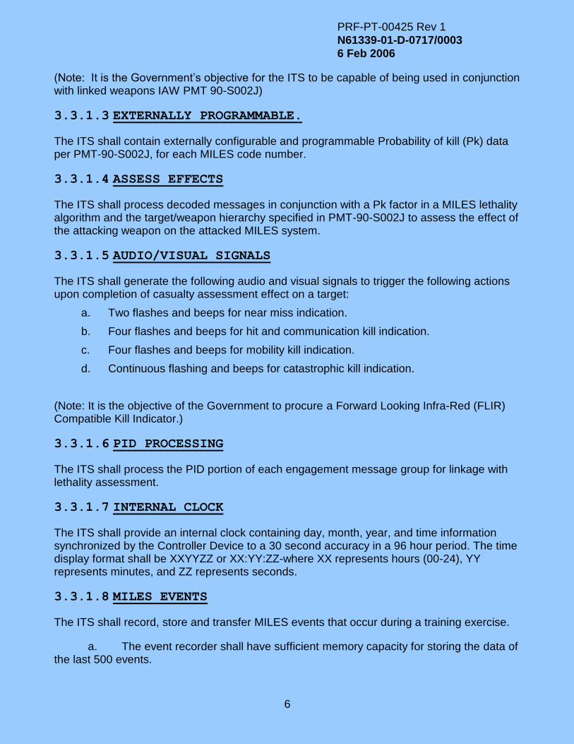
3.3.1.5 AUDIO/VISUAL SIGNALS
The ITS shall generate the following audio and visual signals to trigger the following actions upon completion of casualty assessment effect on a target:
a. Two flashes and beeps for near miss indication.
b. Four flashes and beeps for hit and communication kill indication.
c. Four flashes and beeps for mobility kill indication.
d. Continuous flashing and beeps for catastrophic kill indication.
(Note: It is the objective of the Government to procure a Forward Looking Infra-Red (FLIR) Compatible Kill Indicator.)
3.3.1.6 PID PROCESSING
The ITS shall process the PID portion of each engagement message group for linkage with lethality assessment.
3.3.1.7 INTERNAL CLOCK
The ITS shall provide an internal clock containing day, month, year, and time information synchronized by the Controller Device to a 30 second accuracy in a 96 hour period. The time display format shall be XXYYZZ or XX:YY:ZZ-where XX represents hours (00-24), YY represents minutes, and ZZ represents seconds.
3.3.1.8 MILES EVENTS
The ITS shall record, store and transfer MILES events that occur during a training exercise.
a. The event recorder shall have sufficient memory capacity for storing the data of the last 500 events.

PRF-PT-00425 Rev 1
N61339-01-D-0717/0003
6 Feb 2006
7
b. Recorded data shall be retained under low power conditions and battery removal.
c. The ITS shall be able to transfer the stored event data.
d. The ITS shall retain all stored information for a minimum of 96 hours, regardless of system power status.
3.3.1.8.1 INITIATION EVENTS
The ITS shall record and store the following Initiation events which includes power up.
a. Synchronized time of event
b. Host platform PID
c. Host platform type
d. Built In Test (BIT) results
3.3.1.8.2 LETHALITY ASSESSMENT EVENTS
The ITS shall record and store the following lethality assessment events which includes hit, mobility kill, communication kill, firepower kill, catastrophic kill, and near miss.
a. Synchronized time of event
b. Lethality assessment
c. PID of attacker
d. Weapon and ammunition type (Ammo type N/A for Near Miss and Small Arms)
e. Aspect Angle of attack
f. Determination of fratricide by comparison of shooter and target PID
3.3.1.8.3 CHEAT EVENTS
The ITS shall record and store the following cheat events which includes tampering attempts and motion after mobility kills.
a. Synchronized time of event
b. Cheat category description
3.3.1.8.4 ADMINISTRATIVE EVENTS
The ITS shall record and store the administrative events which includes time synchronization, administrative kills, resurrect, and commanded BIT results.
a. Synchronized time of event
b. Administrative category description

PRF-PT-00425 Rev 1
N61339-01-D-0717/0003
6 Feb 2006
8
3.3.1.9 CASUALTIES
When a casualty has been assessed, during both day and night conditions. The ITS shall display the weapon type causing casualty and the casualty assessment. The message shall remain displayed for 7.5 ±2.5 seconds.
3.3.1.10 RECALL
The ITS shall visually display, upon recall, at least 64 of the most recently recorded events. The scrolled messages shall remain displayed for 7.5 ±2.5 seconds. At a minimum, the following information shall be available for display:
a. Results of last event (Kill/hit/near-miss)
b. PID of attacking player/weapon system when killed
c. Low battery indication
d. BIT failure (by type)
e. Synchronized time of an event in military format to nearest second
3.3.1.11 SELECTION OF VEHICLE TYPE
The ITS shall provide an interface that shall be used to manually select a vehicle type. This action shall require controller personnel interaction and shall not be independently available to the crew.
3.3.1.12 DOWNLOAD CAPABILITY
The ITS shall be able to download vulnerability Pks and other data that programs the device to allow it to assume the role and performance characteristics of the system on which it will be installed. The data to be transferred shall include the following:
a. OPFOR PID
b. BLUEFOR PID
c. Vulnerability and Pk data
3.3.1.13 LOW POWER INDICATOR
The ITS shall provide a low power indication.
3.3.1.14 CHEAT INDICATION
The ITS shall provide a means to detect player efforts to inhibit ITS equipment performance. Whenever the player tampers with an ITS to interfere with normal power supply, cable connections, detectors, semi-permanent memory data storage unit, and controller’s interface when it is locked to the player, the system shall detect a tamper attempt and perform a kill on the ITS. The tamper attempt shall be stored in the event storage.

PRF-PT-00425 Rev 1
N61339-01-D-0717/0003
6 Feb 2006
9
3.3.1.15 RESURRECTION COMMAND
The ITS units shall return to a full operational state without altering the count of remaining ammunition and stop any casualty assessment indication when the ITS detects and decodes the resurrection command.
3.3.1.16 MEMORY CLEAR FUNCTION
The ITS shall contain an event memory clear function to allow only controller personnel to clear the event memory.
3.3.1.17 CATASTROPHIC KILL
The ITS shall perform a MILES catastrophic kill at the time of system power up.
3.3.2 SPECIFIC REQUIREMENTS
The Independent Target System shall perform IAW the following:
a. An Independent Target System configuration for each of the targets listed in Appendix A is required. Each configuration shall provide a means of engagement pairing to a MILES attacker and lethality assessment at the Independent Target System.
b. Each ITS listed in Appendix A shall be configured such that a hit zone representative of the M966 TOW HMMWV target is created.
c. The ITS shall use the target’s Pk and the lethality of the attacker’s weapon and ammunition to assess weapon effects on a target. For Independent Target System configurations, the Independent Target System shall have programmable Pks for the assessments of a mobility kill, communications kill or firepower kill, if a catastrophic kill is not assessed when a hit resulted from an attacking weapon of the type which could cause a catastrophic kill. The Independent Target System shall perform the following actions for each of the kill conditions listed below:
(1) For a catastrophic kill, provide a visual/aural indication to the individuals associated with the target and initiate a catastrophic kill target visual kill indication.
(2) For a mobility kill, provide a visual/aural indication to the crew to stop vehicle motion and initiate a mobility kill target visual kill indication. Twenty seconds after the crew has received notification of a mobility kill, the Independent Target System shall initiate a catastrophic kill if it senses vehicle motion. For a cheat kill, the Independent Target System shall perform the same functions as the catastrophic kill.

PRF-PT-00425 Rev 1
N61339-01-D-0717/0003
6 Feb 2006
10
(3) For a communications kill, provide a visual/aural indication to the individuals associated with the target that a communications kill has been assessed and initiate a communications kill target visual kill indication.
(4) For a firepower kill, provide a visual/aural indication to the crew that a firepower kill has been assessed, and initiate a firepower kill target visual kill indication.
d. The ITS shall perform the following actions in response to a corresponding electronic signal received by the Target System through the data transfer interface:
(1) Perform a lethality assessment and assess the appropriate catastrophic kill, mobility kill, communications kill, or hit
(2) Perform an administrative kill
(3) Indicate a near miss
(4) Reset the Independent Target System
(5) Resurrect the Independent Target System
(6) Synchronize the internal clock
(7) Modify the Pk table of the Independent Target System
(8) Run BIT
(9) Modify the System’s PID
e. The ITS shall store on-board an OPFOR PID, a BLUEFOR PID, and a minimum of 64 vehicle types and their corresponding ammunition types, ammunition basic loads, and vulnerability tables as defined in Appendix B. The PIDs and vehicle types shall be retained in memory such that they are available for selection by authorized personnel upon power up as part of the ITS initialization. The System shall have 26 predefined vehicle types embedded into the system, and 38 user-defined vehicle types that can be overwritten by downloading additional vehicle types and their vulnerability tables to the system.
f. The Control Unit shall be located inside the cab/drivers areas for wheeled vehicles. The Control Unit shall be located inside the turret/crew area for tracked vehicles.
g. The Independent Target System shall provide visual/aural indications when the unit assesses a kill, hit, or near-miss.
h. The time required for an individual to perform mounting and system check-out of the Independent Target System shall be one hour or less. The time required for an individual to remove the Independent Target System shall take one hour or less.
PRF-PT-00425 Rev 1
N61339-01-D-0717/0003
6 Feb 2006
11
3.3.3 BIT CHARACTERISTICS
A built-in fault detection and locating system shall be provided to detect performance degradation and failures and provide GO/ No Go status for all ITS. BIT features shall include the following:
a. Provide an assessment of overall system integrity in not more than 1 minute upon command.
b. Diagnose problems and faults to at least the major component level (excluding vehicle mounting hardware, and transit cases).
c. The ITS shall have a method to self test the battery power level for immediate operation without the use of special tools or modification. This test shall be performed automatically upon battery insertion and shall notify the operator of the battery power status.
d. Function on-line, shall be entirely self-contained, and shall require no external measurement equipment.
e. Display the results of BIT to the system operator when the system has completed an integrity checkout.
f. Power On BIT – The ITS shall automatically initiate a complete BIT sequence in response to powering up the system with results indicated.
g. Manual BIT – The ITS shall initiate a complete BIT sequence in response to a request from the system operator.
3.3.4 COMPUTATIONAL SYSTEM REQUIREMENTS
The ITS computational system shall consist of computer systems and system software.
3.3.4.1 OPERATIONAL COMPUTER SYSTEMS
The operational computer systems shall consist of one or more commercial item processors and peripherals, interface hardware, controllers, and cables. Each processor shall have a word size, operating speed, installed memory, and bus bandwidth to fulfill the system requirements and spare capacity requirements of this Specification. The operational computer system(s) shall provide the following spare resources to allow for expansion and modification. Spare requirements shall be met during worst-case system operating conditions where maximum demands are placed on processors, memories, and I/O channels. The required spare resources are as follows:
a. Spare memory. The system shall provide spare memory for each processor equal to 50% of the installed memory for that processor. Spare memory for any shared memory equal to 50% of the installed memory shall also be provided. All installed spare memory shall be directly addressable by the delivered processor and operating system.
PRF-PT-00425 Rev 1
N61339-01-D-0717/0003
6 Feb 2006
12
b. Spare I/O Capacity. The spare I/O channel throughput capacity shall equal or exceed 50% of the total installed I/O channel capacity.
3.3.4.2 OPERATIONAL SYSTEM SOFTWARE
The operational system software shall consist of one or more of the following: developed software, reusable software, commercial item software, and modified previously-developed software. The system software shall consist of applications programs, support programs, and control programs required to meet the performance requirements.
3.3.4.2.1 SOFTWARE DEVELOPMENT REQUIREMENTS
Software procured under this Contract shall have been developed using recognized modern software engineering methods, and using a commercial item programming language and compiler. All machine dependent code and compiler dependent code shall be logically grouped into separate packages with meaningful names. Adaptation of previously-developed software to make it fully compliant with the ITS requirements shall also be accomplished using recognized modern software engineering methods.
3.3.4.2.2 RUN TIME ENVIRONMENT
If used, the run time environment shall consist of a commercial item real-time operating system.
3.3.4.2.3 FIRMWARE
Code or data which is stored in hardware devices (e.g., in a Programmable Read Only Memory) is software and shall be incorporated into the appropriate Computer Software Configuration Items (CSCI) with the same requirements as other software.
3.3.5 FALSE ALARM RATE
The ITS training system shall have a cumulative false alarm rate of not more than one false alarm per 100 hours of field operations for 50 ITS.
3.3.6 INSTALLATION AND REMOVAL REQUIREMENTS
All ITS systems shall be installed, operated, and removed without physical damage to or permanent modification of the host vehicle and weapon system.
3.3.6.1 MOUNTING DEVICES
Mounting devices shall include all devices required to secure ITS system components to the host platform. For vehicles, mounting devices shall electronically and mechanically couple into the host vehicle system for a training exercise. Fasteners manipulated by the soldiers in the field shall be of the captive type.
PRF-PT-00425 Rev 1
N61339-01-D-0717/0003
6 Feb 2006
13
3.3.6.2 INTERFACING CABLING
Interfacing devices shall include electrical cables, connectors, and couplers to interconnect ITS system components with each other. The cables, connectors, and couplers to interconnect the ITS components to the host vehicle systems shall be provided. All cables attached to either the vehicle or targets shall be by temporary means. All ITS cables shall be clearly marked with designated function, cable part number, connector numbers, and reference designator. Connectors shall be color coded for installation when both mating connectors are being provided within the ITS system.
3.3.7 TRANSIT CASES
The ITS device and system level transit cases shall be used to protect ITS components during transportation, storage, and handling. Where practical, the cases shall hold all the components of one or more kits of a particular configuration. The transit cases shall be built to comply with ATA SPEC 300, category I container. The transit case shall provide protected areas for attachment of all hardware. Top and bottom case surfaces shall be interlocking. Transit cases requiring a four-man lift shall have handles on all four sides.
3.4. POWER
All ITS system and devices shall have a self- contained power system or be powered by the vehicle’s power supply system. If powered by host vehicle power, a self-contained backup power source, independent of the vehicles power supply system, shall be provided. For systems and devices not operated by the vehicle’s power supply, a commercially available power source shall be used.
3.4.1 POWER CONTROL
The ITS power supply shall satisfy the following power control requirements:
a. The Independent Target System shall have an on/off function which restores/inhibits the power from the source to the system. The on/off function shall have a guard to prevent accidental actuation.
b. All ITS components that receive their primary power from a host vehicle power supply system shall perform the following functions:
(1) Operate with and provide a means of protection from vehicle battery voltage and current sags, surges and transients.
(2) Operate within the range of 16 to 33 volts DC, with surges up to 40 volts, with a peak ripple of 7 volts containing a ripple frequency between 50 Hz and 200 kHz.
(3) Provide transient protection in addition to the conducted susceptibility requirements. The transient protection shall be capable of handling a transient of both positive and negative 250 volts with a rise time of 50 nanoseconds recurring at the rate of one transient per second. For these tests, simulated voltage spikes shall be applied to the
PRF-PT-00425 Rev 1
N61339-01-D-0717/0003
6 Feb 2006
14
equipment while it is operating at nominal voltage. The test spike shall have an amplitude of 250 V, a risetime not exceeding 50 nanoseconds, a frequency of oscillation greater than 100 kHz and less than 500 kHz and an energy content of not less than 15 millijoules.
(4) Automatically switch to an auxiliary battery in the event of the loss of vehicle power. In the event of loss of vehicle power, the ITS system shall remain operational with no interruption in performance.
3.4.2 POWER OPERATION
If field replaceable non-rechargeable batteries are used as a power source, the ITS shall provide a minimum of 100 hours of continuous operation without power source replacement when powered from vehicle power. When powered only from the auxiliary battery, the ITS shall be capable of continuous operation for a minimum of 100 hours under the Hot temperature operation49 degrees Celsius with solar loading of 1120 W/m2 for the ITS kit while sustaining at least 20 near miss assessments per day and 2 catastrophic kills per day. When operating solely on auxiliary battery power, the KSI shall flash for a minimum of ten minutes when a catastrophic kill is assessed. If the batteries are not field replaceable, the batteries shall not require replacement more frequently than annually.
3.4.3 BATTERIES
If field replaceable non-rechargeable batteries are used as a power source for a system or device, they shall be easily accessible to the operator or maintenance personnel without need for special tools. The batteries intended to be changed by field personnel shall take no more than one minute to replace. These batteries shall be CECOM certified. The ITS Kits shall use the Raytheon designed Battery Eliminator Device.
3.4.4 RELIABILITY
Each ITS system and device shall have a Threshold acceptable Mean Time Between Essential Functional Failure (MTBEFF) requirement of 910 hours and an objective MTBEFF of 1660 hours.
3.4.5 MAINTAINABILITY
The maximum acceptable Mean Time to Repair (MTTR) for each ITS system and device shall be 60 minutes or less. All equipment shall be easy to maintain and service.
3.5. PHYSICAL CHARACTERISTICS
3.5.1 WEIGHT
All ITS component assemblies shall be transportable and maneuverable by one person. When assembled in their respective operating configuration, the weight of each ITS component shall not exceed that prescribed by the lift and carry requirements. The weight

PRF-PT-00425 Rev 1
N61339-01-D-0717/0003
6 Feb 2006
15
and center of gravity of the ITS devices shall not impede the carrying, movement and functioning abilities of the individual or crew in conducting training.
3.5.2 SIZE
The ITS system components and devices shall be minimized such that they do not impede the carrying, movement, and functioning abilities of the individual, crew, and host platform in conducting training.
3.5.3 FINISH
All exterior surfaces of ITS components and devices shall be treated to resist corrosion or deterioration due to exposure to the elements.
3.5.4 COLOR
Selection of color for all painted surfaces shall be the low visibility, lusterless, nonreflective type. The color of the components mounted on vehicles or personnel shall be green or black, with the exception of surfaces required for the transmission or reception of electromagnetic signals.
3.5.5 TRANSPORTABILITY
Lift limits for devices shall be: One person (Male & Female - assuming 5 ft lift) - 37 pounds, Two-men - 74 pounds, Three-men 101.75 pounds, Four-men - 129.5 pounds. Devices exceeding one person lift limits shall be prominently labeled with the total weight and required number of handlers. All ITS systems, when packed in their transit cases, shall withstand damage due to stresses incidental to movement, handling in transit, and tie-down aboard common carrying vehicles such as aircraft or trucks.
3.6. ENVIRONMENTAL CONDITIONS
Devices and component parts, units, and subassemblies of ITS shall operate and be stored under the environmental conditions as follows:
3.6.1 HIGH TEMPERATURE
ITS system components and devices shall comply with the following temperature requirements:
a. Externally Mounted components shall operate in an environment with a maximum temperature of 49 degrees Celsius and Solar Loading of 1120 W/m².
b. All internally-mounted components shall operate in an environment with a maximum temperature of 49 degrees Celsius.
PRF-PT-00425 Rev 1
N61339-01-D-0717/0003
6 Feb 2006
16
c. All internal and external components shall operate after being stored in an environment with a maximum temperature of 70 degrees Celsius.
3.6.2 LOW TEMPERATURE
Minimum operating temperature shall be -18 degrees C and the minimum storage temperature shall be -33 degrees C.
3.6.3 SHOCK
ITS components and devices shall not be damaged when subjected to the specified shock spectrum of MIL-STD-810E NOTICE 3, Method 516.4, Procedure I - Functional Shock. Components and devices in their transit cases shall not be damaged when subjected to the recommended drop test of Table 516.4-II and Procedure IV - Transit Drop.
3.6.4 VIBRATION
ITS components and devices shall not be damaged when subjected to the specified vibration limits of MIL-STD-810E Notice 3. The requirements of MIL-STD-810E Notice 3 shall be that the components shall not be damaged when subjected to Method 514.4, Category 8 (Ground Mobile).
3.6.5 HUMIDITY
ITS component and devices shall not be damaged during operations under relative humidity conditions up to 100%.
3.6.6 RAIN
ITS components, devices, and all transit cases shall not be damaged when subjected to the following limits. Those components and devices subjected to the immersion test shall not be subjected to the rain test.
Rainfall rate: 10 centimeter/hour
Droplet size: 0.5 millimeter to 4.5 millimeters
Wind velocity: 64 kilometers/hour
3.6.7 SAND AND DUST
ITS components and devices shall not be damaged when subjected to the following limits:

PRF-PT-00425 Rev 1
N61339-01-D-0717/0003
6 Feb 2006
17
Blowing dust air velocity: 8.9 meters/second
Dust concentration: 10.6 ±7 g/cubic meters
Dust composition: Silicon Flour
ITS externally mounted ITS components and devices shall not be damaged when subjected to the following limits:
Blowing sand air velocity: 29 meters/second
Sand concentration: 1.1 ±0.25 g/cubic meters
3.6.8 IMMERSION
ITS components mounted on the outside of the target shall show no evidence of water leakage when immersed in water to a depth of one meter IAW MIL-STD-810E NOTICE 3.
3.6.9 CORROSION
Internal circuitry and components shall be treated to resist corrosion and deterioration due to condensation.
3.6.10 SALT AND FOG
All exterior surfaces, including transit cases, shall be treated to resist corrosion or deterioration. As a minimum performance requirement, these surfaces shall exhibit no blistering, lifting of the coating system, and substrate corrosion after being subjected to a 5% sodium chloride atomized spray as described in MIL-STD-810E Notice 3, Method 509.3.
3.7. CONSTRUCTION
3.7.1 ELECTROMAGNETIC RADIATION.
The equipment shall be electromagnetically compatible with itself such that system operational performance requirements can be met. All hardware intended for field use shall be EMC with all other adjacent operating systems intended for field use. The equipment shall be electromagnetically compatible with the defined external EME such that system operational performance requirements can be met. Inter-system EMC covers compatibility with, but is not limited to, the installation site EME, adjacent facilities and friendly emitters (other MILES equipment (MILES I, MILES 2000, MILES XXI), CB, UHF, VHF, cellular, etc.).
3.7.1.1 CONDUCTED SUSCEPTIBILITY
ITS components and devices shall not exhibit any malfunction, degradation of performance, or deviation from operational parameters when the power leads are subjected to a test signal

PRF-PT-00425 Rev 1
N61339-01-D-0717/0003
6 Feb 2006
18
levels described by MIL-STD-461E, paragraph 5.7.4 for conducted susceptibility, CS101, curve #2, nominal 28 volts DC or below.
3.7.1.2 RADIATED EMISSIONS
The radiated emission limits of MIL-STD-461E, RE102, for electric fields, ground installed equipment, shall be met for the frequency range of ten kHz to 18 GHz. The ITS components and devices when operating shall be not be a source of radiated emissions so as to create electromagnetic interference, malfunctions, degradation of performance, or deviations from operational parameters to adjacent operating electronic or electrical equipment.
3.7.1.3 CONDUCTED EMISSIONS
The conducted emission limits of MIL-STD-461E, CE102, for conducted emissions, power leads, shall be met for the frequency range of ten kHz to ten MHz. The ITS components and devices when operating shall not be a source of conducted emissions so as to create electromagnetic interference, malfunctions, degradation of performance, or deviation from operational parameters to other operating electronic or electrical equipment, when connected to the same source of power or interconnected for the purpose of control or data exchange.
3.7.1.4 RADIATED SUSCEPTIBILITY
The ITS components shall be able to operate in the following radiated electrical field levels without a degradation in performance. FREQUENCY RANGE ELECTRIC FIELD INTENSITY 10 kHz to 2 MHz 20 Volts/meter 2 MHz to 30 MHz 50 Volts/meter 30 MHz to 1 GHz 50 Volts/meter 1 GHz to 18 GHz 50 volts/meter
3.7.2 MATERIAL AND PARTS
The ITS components and devices should maximize the use of commercial and non-developmental products.
3.7.3 NAMEPLATES AND PRODUCT MARKING
The ITS Nameplates shall be provided for each serialized ITS system. Product markings shall be displayed prominently on the transit cases. Nameplates shall include nomenclature, part number, and a unique serial number. All remaining replaceable parts including mounting parts shall be marked with the part number. All cables shall be clearly marked with designated function, cable part number, and connector reference numbers. All assemblies with connectors shall identify the connector reference number on the body of the assembly.
3.7.4 INTERCHANGEABILITY
Interchangeability among common parts of the existing MILES hardware and software shall be required. All parts, assemblies, and units having the same part number shall be directly and completely interchangeable.
PRF-PT-00425 Rev 1
N61339-01-D-0717/0003
6 Feb 2006
19
3.7.5 SYSTEM SAFETY
Any design or modifications shall meet 29 CFR 1910, and National Fire Protection Association Codes. The ITS system shall provide fail-safe features for safety of personnel during installation, operation, maintenance, testing, support activities, and disposal. Commercial item equipment shall be certified as meeting the requirements of a nationally recognized safety testing laboratory (such as Underwriters Laboratory). Training equipment that can be mistaken for tactical equipment shall be marked “FOR TRAINING USE ONLY”. As a minimum, the following areas shall be considered for the ITS systems:
3.7.5.1 ELECTRICAL SAFETY
Electrical circuitry and installation shall comply with the requirements of the National Electric Code (ANSI/NFPA 70-02). Danger, caution, and warning signs shall be designed and used IAW ANSI/NEMA Z535.3-98 and ANSI/NEMA Z535.4-98 to warn user personnel of specific hazards such as voltage, current, and thermal. Batteries shall be sufficiently separated from electronic components to prevent damage from corrosion.
3.7.5.2 HAZARDOUS MATERIALS
The ITS system shall not incorporate any asbestos. Glass fiber materials shall not be used as the outer surface or covering on cables, wire, or other items where they may cause skin irritation to operating personnel. When maintenance procedures require access to glass fibers, such as insulation, a proper caution note shall be provided. Polyvinyl chloride (PVC) materials shall not be used in the crew compartment. Ozone-depleting substances, such as Halon, shall not be used. The ITS training system shall preclude exposure of personnel or the environment to excessive levels of toxic, carcinogenic, or otherwise hazardous materials as defined by the Occupational Health and Safety Administration (OSHA), Environmental Protection Agency (EPA), and the Department of Transportation (DOT).
3.7.5.3 MECHANICAL SAFETY
Moving parts shall be guarded or provided with safety devices to prevent mechanical injury to operator and maintenance personnel. Edges and corners shall be rounded and free from burrs. Center of gravity shall be such that the ITS system components and devices are stable and easy to handle.
3.7.5.4 PERSONNEL SAFETY
The design shall be such as to provide maximum safety to personnel and training system equipment when installing, operating, adjusting, and maintaining the equipment. The ITS shall not exceed steady state or impulse noise levels of 85 dBA for steady-state and 140 dBA for impulse noise. ITS equipment shall be designed and installed so that it can be removed, handled, and lifted safely.
PRF-PT-00425 Rev 1
N61339-01-D-0717/0003
6 Feb 2006
20
3.7.5.5 IONIZING RADIATION
If Cathode Ray Tube (CRT) monitors are used, measurements shall be taken to ensure that monitors do not have a higher x-radiation exposure rate than 0.5 milliroentgen (mR) per hour at a distance of 5 centimeters from an external point as required in section 1020.10 of Public Law 90-602, The Radiation Control for Health and Safety Act.
3.7.5.6 LASER SAFETY
Laser equipment, system design, written operator manuals and maintenance instructions shall conform to CFR Title 21, subchapter J, part 1040. For those requirements of 21 CFR 1040 that cannot be met due to operational requirements, an exemption shall be requested from the Government and ANSI Z136.6-2000 shall be used as the design requirement for the items listed above. If exempted, the laser shall have a label of exemption from FDA standards IAW ANSI Z136.6-2000. Hazard classification shall be IAW ANSI Z136.1-2000.
a. The laser eye safety classification shall be Class 1, or Class 3a and the Nominal Ocular Hazard Distance (NOHD) shall not exceed the following:
Unaided viewing -10 meters
Aided Viewing (using 7 power optics) - 50 meters
b. Labeling shall be IAW ANSI Z136.6-2000, according to the hazard classification, and placed such that it is clearly visible. The wording contained in the upper block of the warning design shall be consistent with the perceived hazard.
3.7.5.7 RADIOACTIVE MATERIAL RESTRICTION IN OPTICAL PRODUCTS
The optical products shall contain no thorium or other source materials, as defined by 10 CRF 40, in excess of 0.05 percent by weight (500 ppm), or other radioactive materials. Optical products are defined as optical glass constituents or raw materials, optical glass components such as windows, filters, reflectors, prisms, beamsplitters, lens elements and fiber optics, optical assemblies, and optical coatings, except for IR objective lenses. Radioactive materials are defined as radioactive material per item in excess of concentrations or in quantities greater than 0.001 microcuries.
3.7.6 HUMAN ENGINEERING
The detail design and functionality of the ITS shall be IAW the following sections of MIL-STD-1472: Control 5.1 (Control/display integration); 5.2 (Visual displays); 5.3 (Audio displays); 5.4 (Controls); 5.5 (Labeling); 5.6 (Anthropometry); 5.9 (Design for maintainer); 5.11.1 Portability of Load Carrying; 5.13 (Hazards and safety); 5.15 (User-computer interface). Additionally, Speech Intelligibility requirements shall be IAW MIL-STD-1472. Intelligibility of synthetic speech will be measured using representative panel of listeners.
PRF-PT-00425 Rev 1
N61339-01-D-0717/0003
6 Feb 2006
21
3.8. FIRST ARTICLE INSPECTION
A sample shall be subjected to first article inspection described in section 4.6.
4 VERIFICATION
4.1. DESIGN VERIFICATION
The matrix in Table I specifies the methods of verification for each of the requirements of Section 3. The Qualification Methods of Table I are defined as follows:
a. Examination (E). Examination is an element of inspection consisting of investigation, without the use of special laboratory appliances or procedures, of supplies and services to determine conformance to those specified requirements that can be determined by such investigations. Examination is generally nondestructive and includes, but is not limited to, the use of sight, hearing, smell, touch, and taste; simple physical manipulation; mechanical and electrical gauging and measurement; and other forms of investigation.
b. Testing (T). Testing is an element of inspection and generally denotes the determination, by technical means, of the properties or elements of supplies, or components thereof, including functional operation, and involves the application of established scientific principles and procedures. Test shall consist of measurement, calculation, and other accepted scientific means to establish that the performance requirements of this Specification are met.
c. Analysis (A). Analysis shall be performed through the review of applicable and adequate documentation to verify that the specified requirements have been met. Verification shall be by mathematical analysis, statistical analysis, sampling the correlation of measured data, and observing test results with calculated expected values, conformance of end items with Contractor-generated specifications and documentation from lower tier supplies, as well as Government-approved configuration item specifications and documentation.
d. Demonstration (D). Demonstrations will be performed through actual exercise of the item to verify that the specified requirements have been met.
e. Certification (C). Certification is an element of inspection to verify that the requirement has been met. Certifications must include documented test results, performance data, analytical data, or vender documentation. The certifications must be made available to Government representatives immediately upon request for review during inspections.
TABLE I. Method of Verification
Requirement
Paragraph
Paragraph Title Test
Paragraph
Qualification
Methods

PRF-PT-00425 Rev 1
N61339-01-D-0717/0003
6 Feb 2006
22
TABLE I. Method of Verification
Requirement
Paragraph
Paragraph Title Test
Paragraph
Qualification
Methods
3.2 ITS N/A N/A
3.2.1 MILES N/A T
3.2.2 Data Transfer N/A A,D,E,T
3.2.3 Direct/Indirect Fire Cue (DIFCUE) Interface
N/A A,D,E,T
3.2.4 MCTC IS Interface N/A A,D,E,T
3.3 System performance N/A A,D,E,T
3.3.1 General Requirements N/A A,D,E,T
3.3.1.1 Decoding Messages 4.5.3 A,D,E,T
3.3.1.2 Compatibility 4.5.3 A,D,E,T
3.3.1.3 Externally Programmable. 4.5.3 A,D,E,T
3.3.1.4 Assess Effects 4.5.3 A,D,E,T
3.3.1.5 Audio/Visual Signals 4.5.3 A,D,E,T
3.3.1.6 PID Processing 4.5.3 A,D,E,T
3.3.1.7 Internal Clock 4.5.3 A,D,E,T
3.3.1.8 MILES Events 4.5.3 A,D,E,T
3.3.1.9 Casualties 4.5.3 A,D,E,T
3.3.1.10 Recall 4.5.3 A,D,E,T
3.3.1.11 Selection of Vehicle Type 4.5.3 A,D,E,T
3.3.1.12 Download Capability 4.5.3 A,D,E,T
3.3.1.13 Low Power Indicator 4.5.3 A,D,E,T
3.3.1.14 Cheat Indication 4.5.3 A,D,E,T
3.3.1.15 Resurrection command 4.5.3 A,D,E,T
3.3.1.16 Memory Clear Function 4.5.3 A,D,E,T
3.3.1.17 Catastrophic Kill 4.5.3 A,D,E,T
3.3.2 Specific 4.5.3 A,D,E,T
3.3.3 BIT Characteristics 4.5.3 A,D,E,T
3.3.4 Computational System Requirements
4.5.3 A,D,E
3.3.4.1 Operational Computer Systems 4.5.3 A,D,E,T
3.3.4.2 Operational System Software 4.5.3 A,D,E,T
3.3.4.2.1 Software Development Requirements
4.5.3 A,D,E,C
3.3.4.2.2 Run Time Environment N/A A,D
3.3.4.2.3 Firmware 4.5.3 A,D,E,T,C
3.3.5 False Alarm Rate N/A A,D,T
3.3.6 Installation and Removal Requirements
N/A A,D,E
3.3.6.1 Mounting Devices N/A A,D,E
3.3.6.2 Mounting Devices N/A A,D,E
3.3.6.2 Interfacing Cabling N/A A,D,E

PRF-PT-00425 Rev 1
N61339-01-D-0717/0003
6 Feb 2006
23
TABLE I. Method of Verification
Requirement
Paragraph
Paragraph Title Test
Paragraph
Qualification
Methods
3.3.7 Transit Cases 4.5.2 A,E,T
3.4 Power N/A A,D
3.4.1 Power Control N/A A,D
3.4.2 Power Operation 4.5.11 A,D,T
3.4.3 Batteries N/A A,D,E
3.4.4 Reliability 4.5.4 T
3.4.5 Maintainability 4.5.5 A,D,T
3.5 Physical characteristics N/A N/A
3.5.1 Weight N/A A,T
3.5.2 Size N/A A,E
3.5.3 Finish N/A A,E,T
3.5.4 Color N/A E
3.5.5 Transportability 4.5.3 A,D,E,T
3.6 Environmental conditions 4.5.6 N/A
3.6.1 High Temperature 4.5.6.1 A,T
3.6.2 Low Temperature 4.5.6.2 A,T
3.6.3 Shock 4.5.6.3 A,T
3.6.4 Vibration 4.5.6.4 A,T
3.6.5 Humidity 4.5.6.5 A,T
3.6.6 Rain 4.5.6.6 A,T,C
3.6.7 Sand and Dust 4.5.6.7 A,T
3.6.8 Immersion 4.5.6.8 A,T
3.6.9 Corrosion 4.5.6.9 A,E
3.6.10 Salt and Fog 4.5.6.10 A,T,C
3.7 Construction N/A N/A
3.7.1 Electromagnetic RadiationError!
Reference source not found.
4.5.7 A, T
3.7.1.1 Conducted SusceptibilityError!
Reference source not found.
4.5.7.2 A, T
3.7.1.2 Radiated EmissionsError!
Reference source not found.
4.5.7.3 A, T
3.7.1.3 Conducted EmissionsError!
Reference source not found.
4.5.7.4 A, T
3.7.1.4 Radiated Susceptibility 4.5.7.5 A, T
3.7.2 Material and Parts N/A C
3.7.3 Nameplates and product marking N/A E
3.7.4 Interchangeability 4.5.8 D,E,T
3.7.5 System Safety 4.5.9 A,D,E,T
3.7.5.1 Electrical Safety 4.5.9.1 A,D,E,T
3.7.5.2 Hazardous Materials 4.5.9.2 A,C,E
3.7.5.3 Mechanical Safety 4.5.9.3 A,D,E,T

PRF-PT-00425 Rev 1
N61339-01-D-0717/0003
6 Feb 2006
24
TABLE I. Method of Verification
Requirement
Paragraph
Paragraph Title Test
Paragraph
Qualification
Methods
3.7.5.4 Personnel Safety 4.5.9.4 A,D,E,T
3.7.5.5 Ionizing Radiation 4.5.9.5 A,D,E,T
3.7.5.6 Laser Safety 4.5.9.6 A,D,E,T
3.7.5.7 Radioactive Material Restriction in Optical Products
4.5.9.7 A,C,E
3.7.6 Human engineering N/A A,D,E
3.8 First Article inspection 4.6 A,D,T
4.2. VERIFICATION METHODS
The verification methods shall be on hardware systems and subsystems to ensure compliance with the following characteristics. If a Specification characteristic is identical for several subsystems, Approval may be obtained to perform qualification on a representative subsystem.
4.3. INTEGRATION TESTS
Integration Tests are Contractor conducted/Government witnessed tests conducted at Contractor facility. Integration Tests shall demonstrate the ITS performs in accordance to the specification. During these tests, the ITS software shall be tested in accordance to the test procedures approved by the Government to determine if that the software passes through the various software paths to determine that the software is robust and can handle abnormal inputs as well inputs that cover maximum, minimum and average data inputs.
4.4. SYSTEM VERIFICATION TESTS (SVT)
System Verification Tests (SVT) are Contractor conducted/ Government witnessed tests at Contractor facility. SVTs shall demonstrate that the ITS kits are compliant to the requirements in this specification. During these tests, various ITS kits shall be used in multiple configurations with other training devices to determine if there are any deviations that requiring fixing.
4.5. SYSTEM INTEGRATION TESTS (SIT)
System Integration Tests (SIT) is a government conducted/Contractor supported test at Government facility. SIT shall be used to determine if the ITS works in a Force-on – Force environment. This test is a large scale test that will fully exercise the devices. This test shall be used as the acceptance test for the ITS. The test shall capture training data from all players (BLUFOR and OPFOR) and validate that the correct data is transmitted between the players.
4.5.1 OPERATIONAL SYSTEM SOFTWARE
The software code and documentation shall be examined to ensure that it is compliant with

PRF-PT-00425 Rev 1
N61339-01-D-0717/0003
6 Feb 2006
25
ITS requirements, see paragraph 4.3 above.
4.5.1.1 SOFTWARE DEVELOPMENT REQUIREMENTS
The contractor shall provide the Government with documentation on any new software. The contractor shall also provide licenses for any COTS software. The Government will verify that all software functional characteristics are correctly documented. The Government will also verify the completeness of each software item and reproducibility of all databases and executable code from source files. Not later than 45 days prior to contract completion, the contractor shall provide software configuration audit documents that include, but are not limited to the Interface Control Document and the Software Design Document.
4.5.1.2 FIRMWARE
The Contractor shall certify that any firmware developed meets the same developmental requirements as the software.
4.5.2 TRANSIT CASES
The ITS system level transit cases shall be tested to ensure protection of ITS unit components during transportation, storage, and handling. The transit cases shall be verified by testing to ensure they meet the requirements of: High Temperature, Low Temperature, Shock, Vibration, Rain, and Corrosion.
4.5.3 TRANSPORTABILITY
The transportability requirements shall be verified by analysis, demonstration, certification, and examination. Verification that the ITS hardware does not exceed the weight and balance envelope shall be by demonstration and analysis. Verification that the ITS components and support equipment are housed in designated containers shall be by analysis and examination. Label requirements shall be verified by examination.
4.5.4 RELIABILITY
The reliability requirements shall be verified by a Reliability Qualification Test (RQT). The RQT shall be conducted in accordance with an RQT Plan.
4.5.5 MAINTAINABILITY
A MTTR of 60 minutes or less for each ITS device shall be verified by demonstration and test.
4.5.6 ENVIRONMENTAL CONDITIONS
The environmental requirements shall be considered verified after successful completion of the following tests: high temperature, low temperature, shock, vibration, humidity, rain, sand and dust, leakage, corrosion, and salt fog. The component parts, units, and subassemblies

PRF-PT-00425 Rev 1
N61339-01-D-0717/0003
6 Feb 2006
26
of ITS operate and be stored under the conditions described below:
a. Arrange if desired to allow the post-test inspection and operational checkout for preceding test to serve as the pre-test inspection and operational checkout for the next test.
b. Perform tests on a selected sample of each type of ITS equipment. In the event of a failure of a sample to satisfactorily complete a test, the Contractor shall inspect every component of that type for the presence of a fault responsible for failure and shall correct such fault prior to randomly selecting the next sample for retest. No percentage defective is allowable.
c. Unmodified, stand-alone commercial equipment which is covered for repair or replacement by an original equipment manufacturer's warranty and/or which is tested to MIL-STD-810E Notice 3 requirements equal or higher than specified herein shall be certified as conforming without necessity for additional environmental testing.
4.5.6.1 HIGH TEMPERATURE
The High Temperature requirements shall be verified by test IAW MIL-STD-810E Notice 3, Method 505.3, Procedure I, for all externally-mounted components. Internally and externally-mounted components shall be tested IAW accordance with MIL-STD-810E Notice 3, Method 501.3, Procedure I - Storage. The internally-mounted components shall be tested IAW MIL-STD-810E Notice 3, Method 501.3, Procedure II - Operating. The following conditions shall apply:
Procedure I - Solar Radiation Operating
a. The high temperature requirement shall be +49 degrees C for operation and 1120 W/m2.
b. The test unit shall be fully assembled into its operation state, with power applied.
c. Temperature sensors shall be located on the exterior surface of the test unit.
d. The test shall consist of three 24 hour cycles.
e. An operational check-out shall be conducted during the period of maximum response in each temperature cycle and at the conclusion of the test.
Procedure I - Storage
a. The high temperature storage requirement shall be +70 degrees C.
b. The test unit shall be properly packaged and in its storage configuration.
c. The temperature sensors shall be located on the exterior surface of the test unit.
PRF-PT-00425 Rev 1
N61339-01-D-0717/0003
6 Feb 2006
27
d. The test shall be conducted for seven cycles (each cycle shall be 24 hours in duration).
e. An operational check-out shall be conducted at the conclusion of the test.
Procedure II - Operation
a. The high temperature requirement shall be +49 degrees C for operation.
b. The test unit shall be fully assembled into its operation state, with power applied.
c. Temperature sensors shall be located on the exterior surface of the test unit.
d. The test shall consist of three 24 hour cycles.
e. An operational check-out shall be conducted during the period of maximum response in each temperature cycle and at the conclusion of the test.
4.5.6.2 LOW TEMPERATURE
The Low Temperature requirements shall be verified by test IAW MIL-STD-810E Notice 3, Method 502.3, Procedures I (Mild Cold, Induced for 24 hours), MIL-STD-810E Notice 3, Method 502.3 Procedure II (Basic Cold, Operational, for three cycles), and the following conditions:
Procedure I - Storage
a. The low temperature storage requirement shall be -33 degrees Celsius.
b. The test unit shall be properly packaged and in its storage configuration.
c. The temperature sensors shall be located on the exterior surface of the test unit.
d. The test shall be conducted for three cycles (24 hours).
e. An operational check-out shall be conducted at the conclusion of the test.
Procedure II - Operation
a. The low temperature requirement shall be -18 degrees Celsius for operation.
b. The test unit shall be fully assembled into its operation state.
c. Temperature sensors shall be located on the exterior surface of the test unit.
d. The test shall consist of three 24 hour cycles.
e. An operational check-out shall be conducted at the last hour of each 24 hour cycle and at the conclusion of the test.

PRF-PT-00425 Rev 1
N61339-01-D-0717/0003
6 Feb 2006
28
4.5.6.3 SHOCK
The Shock requirements shall be verified by test IAW MIL-STD-810E Notice 3, Method 516.4 Procedure I - Functional Shock, Figure 516.4-4. Components and devices in their transit cases shall also be subjected to the recommended drop test of Table 516.4-II and Procedure IV - Transit Drop.
a. The test unit system shall be fully assembled into its operation state for Procedure I.
b. For Procedure I, use the Operational Test For Ground Equipment test shock response spectrum of Figure 516.5-10.
c. An operational check-out shall be conducted at the conclusion of the test.
4.5.6.4 VIBRATION
Any system component that is used on more than one vehicle shall be verified once using the vibration program data of the most severe platform. The Vibration requirements shall be verified IAW MIL-STD-810 as follows:
Method 514.4, Category 8 (Ground Mobile): Table 514.4-AXVII
a. The test unit shall be fully assembled into its operational state.
b. The narrowband random-on-random vibration program data defined by the table listed in Table II shall be used.
c. The M1A1 vibration test phases shall be run for 60 minutes and the M113 vibration test phases shall be run for 45 minutes, for a test time of 270 minutes per axis, and a total test time of 12 hours.
d. An operational check-out shall be conducted at the conclusion of the test.
Vehicle System MIL-STD-810E Notice 3
APPENDIX A
Table
Table
Description
Independent Target System
514.4-AII Secured Cargo Transportation,
Composite Wheeled Vehicle
Table II
Method 514.4, Category 3 (Loose Cargo)
PRF-PT-00425 Rev 1
N61339-01-D-0717/0003
6 Feb 2006
29
a. Procedure III - Category 3 - Loose cargo transport shall be performed for a duration of 30 minutes.
b. An operational checkout shall be performed at the conclusion of the test.
4.5.6.5 HUMIDITY
The Humidity requirements shall be verified IAW MIL-STD 810E Notice 3, Method 507.3 Procedure I (Natural), Cycle 3, with the following requirements:
a. The test unit shall be fully assembled into its operation state.
b. The test cycle used shall be as defined by Figure 507.3-I.
c. Each cycle shall be 24 hours in duration.
d. The test duration shall be for ten cycles with a quick look and operational check-out after the fifth cycle.
e. For "Group C" testing, the duration shall be two cycles.
f. An operational check-out shall be conducted at the conclusion of the test.
4.5.6.6 RAIN
The Rain requirements shall be verified by test IAW MIL-STD-810E Notice 3, Method 506.3 Procedure I - Blowing Rain. The test unit shall be subjected to the following limits:
a. The test unit shall be fully assembled into its operation state.
b. The rainfall rate shall be a minimum of four inches per hour.
c. The wind velocity shall be a minimum of 40 miles per hour.
d. The temperature of the test unit shall be at least ten degrees Celsius greater than the rain temperature at the beginning of each 30 minute exposure period.
e. The test shall be conducted for a period of 30 minutes per face until all faces have been exposed.
f. The failure criteria shall be degradation of performance of the test unit following the rain test and unconditional failure as defined in MIL-STD-810E Notice 3, Method 506.3, paragraph I-4.1.2.
g. An operational check-out shall be conducted at the end of the test.
h. The transit case requirement shall be verified by the above test procedure or through certification, by manufacturer, of analogous test procedures and data.
PRF-PT-00425 Rev 1
N61339-01-D-0717/0003
6 Feb 2006
30
4.5.6.7 SAND AND DUST
The Sand and Dust requirements shall be verified by test IAW MIL-STD-810E Notice 3, Method 510.3, when subjected to the following limits (Test items shall be powered on during test):
a. Sand. The test unit shall be tested IAW MIL-STD-810, Method 510.3, Procedure II, for blowing sand, and with the following requirements:
1. The test unit shall be fully assembled into its operation state and all optics, windows and front panels shall be protected.
2. The sand particle size shall be from 0.15 to 0.85 millimeters and the concentration of 1.1 grams per cubic meter.
3. The air velocity in the test chamber shall be from 18 to 29 meters per second.
4. The test shall be conducted for a period of 90 minutes per face until all faces have been exposed.
5. An operational check-out shall be conducted at the conclusion of the test.
b. Dust. The test unit shall be tested IAW MIL-STD-810, Method 510.3, Procedure I for blowing dust, and with the following requirements:
1. The test unit shall be fully assembled into its operation state.
2. The dust particle size shall be from 0.0001 to 0.01 millimeters and the concentration of 10.6 grams per cubic meter.
3. The air velocity in the test chamber shall be 8.9 meters per second.
4. The test shall be conducted for six hours at +23 degrees Celsius and six hours at +49 degrees Celsius, with an operational check conducted during the second test period.
5. An operational check-out shall be conducted at the conclusion of the test.
4.5.6.8 IMMERSION (LEAKAGE)
The Immersion requirements shall be verified IAW MIL-STD 810E Notice 3, Method 512.3, Procedure I - Basic Leakage.
a. The test unit shall be fully assembled into its operation state and the following:
b. The test unit temperature shall be stabilized to 27 degrees C above the water temperature, with the water temperature at 18 ±10 degrees C.
PRF-PT-00425 Rev 1
N61339-01-D-0717/0003
6 Feb 2006
31
c. The immersion depth shall be one meter and immersion period of two hours.
d. Observations for air bubbles originating from the unit shall be done.
e. After completion the test unit shall be examined for water content inside the unit. Evidence of water penetration into the test unit following the immersion test or not completing the operational check-out at the conclusion of the test shall be basis for failure.
4.5.6.9 CORROSION
The Corrosion requirements shall be verified by examination and analysis.
4.5.6.10 SALT AND FOG
The Salt and Fog requirements shall be verified IAW MIL-STD-810E Notice 3, Method 509.3 for Salt Fog climatic tests, and with the following requirements:
a. The test unit shall be fully assembled into its operation state.
b. The solution concentration shall be five percent ± one percent.
c. The test unit shall be exposed alternating 48-hour periods of salt fog exposure and drying conditions for a minimum of four 48-hour periods (two wet and two dry).
d. An operational check-out shall be conducted at the conclusion of the test.
e. Failure criteria shall be any noticeable corrosion or blistering on the interior or exterior of the test unit, or failure to properly perform during the operational check-out at the conclusion of the test.
f. The transit case requirement of 4.2.2 shall be verified by the above test procedure or through manufacturer certification of analogous test procedures and data.
4.5.7 ELECTROMAGNETIC RADIATION
The safety critical functions shall be verified to be electromagnetically compatible with the E3 generated by the ITS systems/ subsystems/components and with installation site electromagnetic environments prior to operator use at the ITS installation sites.
4.5.7.1 CONDUCTED SUSCEPTIBILITY
The Contractor shall test the ITS components and verify IAW MIL-STD-461E, Method CS101. The ITS shall not exhibit any malfunction, degradation of performance, or deviation from operational parameters when the power leads are subjected to a test signal levels as
described in Section Error! Reference source not found..
PRF-PT-00425 Rev 1
N61339-01-D-0717/0003
6 Feb 2006
32
4.5.7.2 RADIATED EMISSIONS
The Contractor shall test the ITS components and verify IAW MIL-STD-461E, Method RE102 to ensure that it does not emit any signals above the established threshold from 10 kHz to 18 GHz. The ITS components when operating shall be not be a source of radiated emissions so as to create electromagnetic interference, malfunctions, degradation of performance, or deviations from operational parameters to adjacent operating electronic or electrical
equipment as described in Section Error! Reference source not found..
4.5.7.3 CONDUCTED EMISSIONS
The Contractor shall test the ITS components and verify IAW MIL-STD-461E, Method CE102 to ensure that it does not emit any signals above the established threshold from 10 kHz to 10 MHz. The ITS components when operating shall not be a source of conducted emissions so as to create electromagnetic interference, malfunctions, degradation of performance, or deviation from operational parameters to other operating electronic or electrical equipment, when connected to the same source of power or interconnected for the purpose of control or
data exchange as described in Section Error! Reference source not found..
4.5.7.4 RADIATED SUSCEPTIBILITY
The Contractor shall test the ITS components and verify IAW MIL-STD-461E to ensure that it is not susceptible to signals from 10kHz to 18 GHz. The components shall not exhibit any malfunction, degradation of performance, or deviation from operational parameters when
subjected to radiated levels as described in Section Error! Reference source not found..
4.5.8 INTERCHANGEABILITY
The Interchangeability requirement shall be verified by a test that shall demonstrate interchangeability of circuit card assemblies, spare part assemblies, and devices. A functional test or demonstration of fit shall be conducted after each interchangeability trial. No degradation of performance shall be allowed. Verification shall include certification that all circuit card assemblies, spare parts, and devices are fit, function and interface interchangeable with ITS devices.
4.5.9 SYSTEM SAFETY
The Contractor shall verify the following requirements of each configuration described in Appendix A and the System Safety requirements of this Specification. By analysis, examination, demonstration and test, the Contractor shall complete and verify compliance to the applicable items on the safety checklist provided in Appendix C. The System Safety requirements shall be considered verified after successful completion of requirements outlined in Table I along with those stated in this Section.
4.5.9.1 ELECTRICAL SAFETY
The Contractor shall verify by analysis, examination, demonstration, and test that the electrical circuitry and installation meet applicable requirements of the National Electrical Code (ANSI/NFPA 70-93). The Contractor shall provide a list of all danger, caution, and

PRF-PT-00425 Rev 1
N61339-01-D-0717/0003
6 Feb 2006
33
warning signs installed in the ITS equipment and incorporated into applicable Technical Manuals (TM) and Publications. This list, which shall include design and wording of each sign IAW ANSI/NEMA Z535.3-91/Z535.4-91, shall be attached to Appendix C. The completed safety checklist-Appendix C shall be submitted and demonstrated to the Government as part of physical safety inspections of each ITS major component. The Contractor shall verify by analysis and test that the installation, operation, handling, and maintenance of batteries used with the ITS equipment does not present safety or health hazards for user personnel or damage associated equipment.
4.5.9.2 HAZARDOUS MATERIALS
The Contractor shall confirm by analysis, examination, and certification that the ITS equipment does not incorporate any asbestos or ozone-depleting substances, that glass fiber materials are not used as the outer surface or covering on cables, wire, or other items where they may cause skin irritation to operating personnel, and that PVC materials are not used in the crew compartments. The Contractor shall demonstrate by analysis and certification that the ITS kit does not expose personnel or the environment to unacceptable levels of toxic, carcinogenic, or otherwise hazardous materials as defined by OSHA, EPA, or DOT. The Contractor shall attach to the completed Appendix C any applicable Material Safety Data Sheets along with any required warning signs on equipment and procedures/warnings in TMs and Publications.
4.5.9.3 MECHANICAL SAFETY
The Contractor shall verify by analysis, examination, demonstration, and test that any moving parts of the ITS equipment are properly guarded or provided with safety devices to prevent injury to operator and maintenance personnel, that any edges or corners are rounded and free from burrs, and that the ITS equipment’s center of gravity is such that components and devices are stable and easy to handle. The Contractor shall attach to Appendix C any applicable warning signs to equipment or warnings to related TMs and publications.
4.5.9.4 PERSONNEL SAFETY
The Contractor shall verify by analysis, demonstration, examination, and test that the ITS noise generating devices do not exceed impulse and steady state noise level requirements defined in this Specification. The Contractor shall also verify by analysis, examination, demonstration, and test that the ITS equipment meets safety and health requirements of MIL-STD-1472, paragraphs 5.9.11.3, 5.9.11.5, and 5.13. The Contractor shall attach to the completed Appendix C the design and wording of warning signs installed in equipment along with warnings incorporated into TMs and publications as related to personnel safety.
4.5.9.5 IONIZING RADIATION
The Contractor shall verify by analysis, demonstration, examination, and test that, IAW Section 1020.10 of Public Law 90-602, no x-radiation equipment has an exposure rate higher than 0.5 mR per hour at a distance of five centimeters from an external point. The Contractor shall attach to the completed Appendix C the design and wording of warning signs
PRF-PT-00425 Rev 1
N61339-01-D-0717/0003
6 Feb 2006
34
installed in equipment along with warnings incorporated into TMs and publications as related to ionizing radiation.
4.5.9.6 LASER SAFETY
The Contractor shall verify by analysis, demonstration, examination, and test that laser equipment, system design, written TMs, and maintenance instructions meet the requirements of CFR Title 21, subchapter J, Part 1040. The Contractor shall submit an exemption to, and obtain an approval from, the Government to those requirements of 21 CFR 1040 that can not be met due to operational requirements in accordance to laser safety requirements defined in Laser Safety of this Specification. IAW ANSI Z136.1-2000, the Contractor shall install on the equipment applicable laser safety labels along with incorporating applicable warnings in TMs and publications. The Contractor shall attach to the completed Appendix C the design and wording of warning labels and warnings as related to laser safety.
4.5.9.7 RADIOACTIVE MATERIAL RESTRICTIONS IN OPTICAL PRODUCTS
The Contractor shall verify by analysis, examination, and certification that the ITS equipment does not incorporate any thorium or other source materials, or other radioactive materials as defined in Radioactive Material Restriction in Optical Products of this Specification. The Contractor shall attach to the completed Appendix C any applicable Material Safety Data Sheets along with any required warning signs on equipment and procedures/warnings in the TMs and Publications.
4.5.10 TARGET VISUAL KILL STATUS OBSERVATION
The Target Visual Kill Status Indicator shall be positioned six feet above the ground. Observation for flash shall be made with at least five non-Contractor personnel positioned 1800 meters distance. At least one observer shall be a Government representative. The test shall be conducted during standard clear conditions. The observer shall be notified prior to each firing in order to alert them to watch for the flash. The observers shall also be notified after each flash to inform them that the flash took place, allowing for them to record their observations. Observations shall be recorded as visible or non-visible. Three out of five of the observers must record a visible observation for the flash to be deemed visible.
4.5.11 POWER OPERATION
The power operation shall be tested using the worst case scenario of Hot Temperature operation of 49 degrees Celsius and solar loading of 1120 W/m2for a 100 hours.
4.6. FIRST ARTICLE INSPECTION
First article inspection shall be performed on initial production samples. Approval of the first article by the Government shall not relieve the contractor of the obligation to supply ITS systems that are fully representative of those inspected as a first article sample. Any changes or deviation of the production units from the first article sample shall be subject to
PRF-PT-00425 Rev 1
N61339-01-D-0717/0003
6 Feb 2006
35
the approval of the contracting officer.
5 PACKAGING
For acquisition purposes, the packaging requirements shall be as specified in the contract. When actual packaging of materiel is to be performed by DoD personnel, these personnel need to contact the responsible packaging activity to ascertain requisite packaging requirements. Packaging requirements are maintained by the Inventory Control Point’s packaging activity within the Military Department or Defense Agency, or within the Military Department’s System Command. Packaging data retrieval is available from the managing Military Department’s or Defense Agency’s automated packaging files, CD-ROM products, or by contacting the responsible packaging activity.
6 NOTES
(This section contains information of a general or explanatory nature which may be helpful, but is not mandatory.)
6.1. ADAPTABILITY
The ITS system shall be adaptable to weapon systems currently under development and future weapon systems for which detailed data on configuration, lethality, and other weapon/platform data is not yet available.
6.1.1 ABBREVIATIONS AND ACRONYMS
The following list of abbreviations and acronyms are stated in this Specification.
ABBREVIATION TERM AAR After Action Review AC Alternating Current AEL Accessible Emission Limit ANSI American National Standards Institute ATA Air Transport Association BIT Built In Test CRF Code of Federal Regulations CSCI Computer Software Configuration Item CVS Combat Vehicle System DIFCUE Direct/Indirect Fire Cue DOD Department of Defense DOT Department of Transportation DSL Document Summary List E3 Electromagnetic Environmental Effects EMC Electromagnetic Compatible EME Electromagnetic Environment EPA Environmental Protection Agency HMMWV High Mobility Multipurpose Wheeled Vehicle

PRF-PT-00425 Rev 1
N61339-01-D-0717/0003
6 Feb 2006
36
ABBREVIATION TERM IAW In Accordance With IEEE Institute of Electrical and Electronic Engineers I/O Input/Output IR Infrared Red ITS Independent Target System IWS Individual Weapon System MCC97 MILES Communication Code MGSS Main Gun Signature Simulator MILES Multiple Integrated Laser Engagement System MR Milliroentgen MTBEFF Mean Time Between Essential Functional Failure
MTTR MEAN Time to Repair NDI Non-Developmental Item OSHA Occupational Health and Safety Administration PC Personal Computer PDA Personal Digital Assistant PID Player Identification Pk Probability of kill PEOSTRI Program Executive Office Simulation, Training, and
Instrumentation PVC Polyvinyl chloride RETS Remote Target System SAW Squad Automatic Weapon STRICOM Simulation, Training, and Instrumentation Command TES Tactical Engagement Simulation TM Technical Manuals TOW Tube-launched Optically-tracked Wire-guided Missile WESS Weapon Effects Signature Simulator
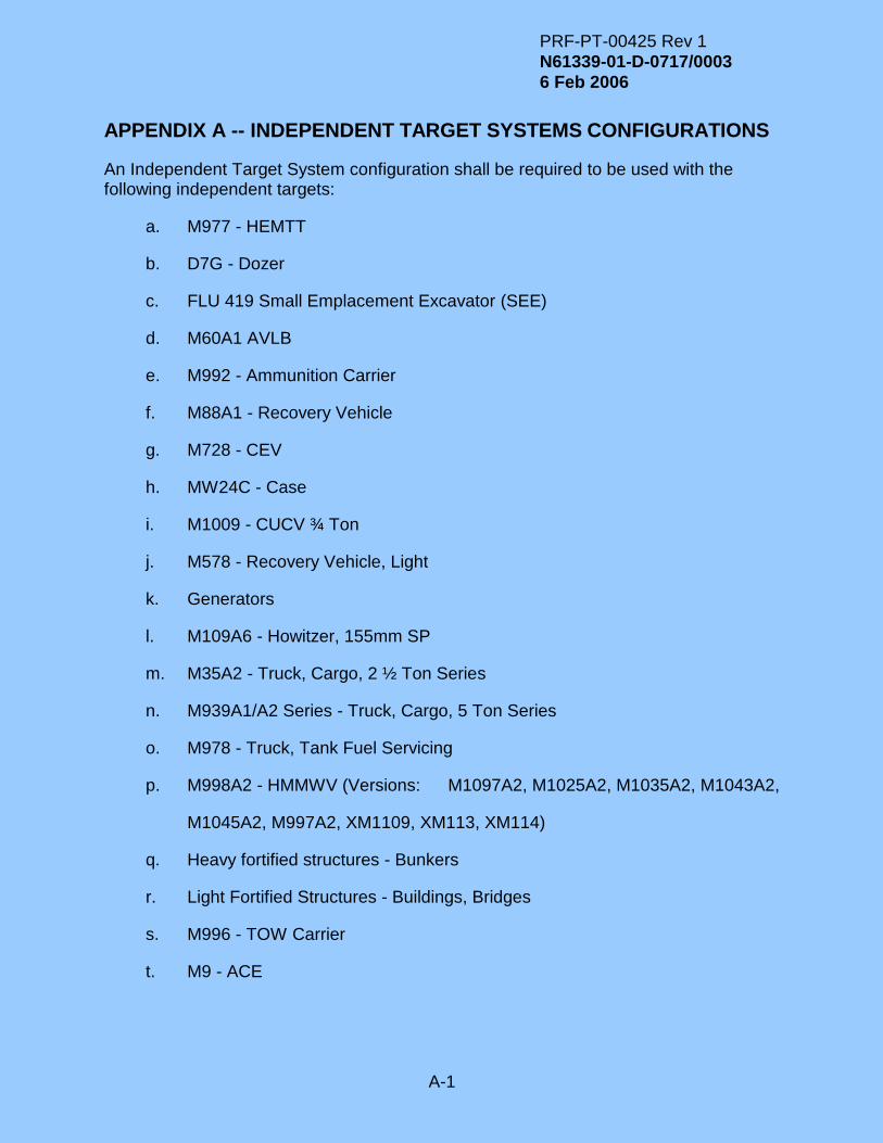
PRF-PT-00425 Rev 1
N61339-01-D-0717/0003
6 Feb 2006
A-1
APPENDIX A -- INDEPENDENT TARGET SYSTEMS CONFIGURATIONS
An Independent Target System configuration shall be required to be used with the following independent targets:
a. M977 - HEMTT
b. D7G - Dozer
c. FLU 419 Small Emplacement Excavator (SEE)
d. M60A1 AVLB
e. M992 - Ammunition Carrier
f. M88A1 - Recovery Vehicle
g. M728 - CEV
h. MW24C - Case
i. M1009 - CUCV ¾ Ton
j. M578 - Recovery Vehicle, Light
k. Generators
l. M109A6 - Howitzer, 155mm SP
m. M35A2 - Truck, Cargo, 2 ½ Ton Series
n. M939A1/A2 Series - Truck, Cargo, 5 Ton Series
o. M978 - Truck, Tank Fuel Servicing
p. M998A2 - HMMWV (Versions: M1097A2, M1025A2, M1035A2, M1043A2,
M1045A2, M997A2, XM1109, XM113, XM114)
q. Heavy fortified structures - Bunkers
r. Light Fortified Structures - Buildings, Bridges
s. M996 - TOW Carrier
t. M9 - ACE

PRF-PT-00425 Rev 1
N61339-01-D-0717/0003
6 Feb 2006
B-1
APPENDIX B –INDEPENDENT TARGET VULNERABILITY TABLES
See PMT 90-S002J
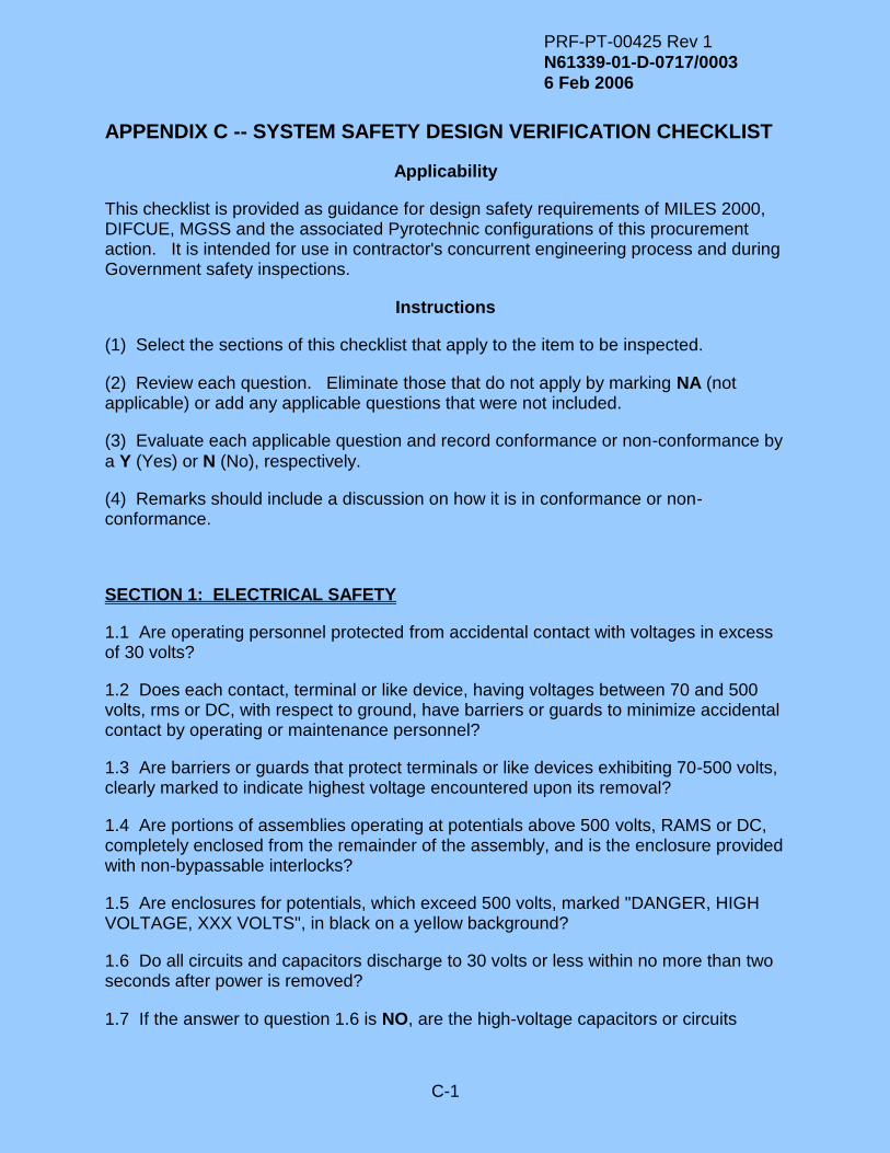
PRF-PT-00425 Rev 1
N61339-01-D-0717/0003
6 Feb 2006
C-1
APPENDIX C -- SYSTEM SAFETY DESIGN VERIFICATION CHECKLIST
Applicability
This checklist is provided as guidance for design safety requirements of MILES 2000, DIFCUE, MGSS and the associated Pyrotechnic configurations of this procurement action. It is intended for use in contractor's concurrent engineering process and during Government safety inspections.
Instructions
(1) Select the sections of this checklist that apply to the item to be inspected.
(2) Review each question. Eliminate those that do not apply by marking NA (not applicable) or add any applicable questions that were not included.
(3) Evaluate each applicable question and record conformance or non-conformance by
a Y (Yes) or N (No), respectively.
(4) Remarks should include a discussion on how it is in conformance or non-conformance.
SECTION 1: ELECTRICAL SAFETY
1.1 Are operating personnel protected from accidental contact with voltages in excess of 30 volts?
1.2 Does each contact, terminal or like device, having voltages between 70 and 500 volts, rms or DC, with respect to ground, have barriers or guards to minimize accidental contact by operating or maintenance personnel?
1.3 Are barriers or guards that protect terminals or like devices exhibiting 70-500 volts, clearly marked to indicate highest voltage encountered upon its removal?
1.4 Are portions of assemblies operating at potentials above 500 volts, RAMS or DC, completely enclosed from the remainder of the assembly, and is the enclosure provided with non-bypassable interlocks?
1.5 Are enclosures for potentials, which exceed 500 volts, marked "DANGER, HIGH VOLTAGE, XXX VOLTS", in black on a yellow background?
1.6 Do all circuits and capacitors discharge to 30 volts or less within no more than two seconds after power is removed?
1.7 If the answer to question 1.6 is NO, are the high-voltage capacitors or circuits

PRF-PT-00425 Rev 1
N61339-01-D-0717/0003
6 Feb 2006
C-2
automatically discharged when the case or rack is opened?
1.8 Are test points provided in equipment where measurement of potentials in excess of 300 volts is required?
1.9 Are test points designed to require plug-in, not clamp-on, test instruments?
1.10 Are green indicator lamps provided to indicate "power on"?
1.11 Is sufficient space provided between shield endings and exposed conductors to prevent shorting or arcing?
1.12 Are electrical conductors designed to prevent insertion of the wrong plug into a receptacle or other mating unit?
1.13 Are plugs and receptacles coded and marked to clearly indicate mating connectors, where those of similar configuration are in close proximity?
1.14 Are plugs and receptacles designed to preclude electrical shock and burns while being disconnected?
1.15 Are male plugs de-energized when disconnected?
1.16 Are dissimilar plug/receptacle pairs used in units containing explosives?
1.17 When equipment is designed to operate on more than one type of input power, does the connector design prevent connection or use of improper power?
1.18 Are single-phase power cables properly color coded:
Black: hot; White: neutral; Green: ground?
1.19 Are three-phase power cables coded as in Question 1.18, above, with the second and third phases in red and blue, respectively?
1.20 Are meter terminals protected from voltages of 70 volts or more?
1.21 Do probes that are part of or accessories to the equipment contain safety guards that prevent contact with the tip and is the length of the exposed portion of the tip not more than 0.75 inches? (This question does not apply if the voltages to be measured are less than (a) 30 volts rams, (b) 60 volts DC, or (c) 24.8 volts DC interrupted at a rate of 10 Hz to 200 Hz.)
1.22 Are current and voltage overload protection devices provided?
1.23 Except for antennas and transmission line terminals, are all external parts, surfaces, and shields at ground potential at all times?
1.24 Is the path from the equipment to ground continuous and permanent?
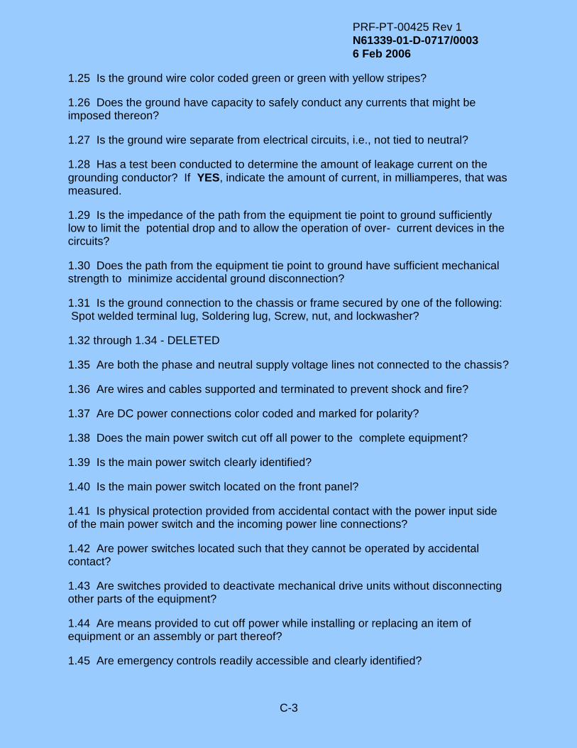
PRF-PT-00425 Rev 1
N61339-01-D-0717/0003
6 Feb 2006
C-3
1.25 Is the ground wire color coded green or green with yellow stripes?
1.26 Does the ground have capacity to safely conduct any currents that might be imposed thereon?
1.27 Is the ground wire separate from electrical circuits, i.e., not tied to neutral?
1.28 Has a test been conducted to determine the amount of leakage current on the
grounding conductor? If YES, indicate the amount of current, in milliamperes, that was measured.
1.29 Is the impedance of the path from the equipment tie point to ground sufficiently low to limit the potential drop and to allow the operation of over- current devices in the circuits?
1.30 Does the path from the equipment tie point to ground have sufficient mechanical strength to minimize accidental ground disconnection?
1.31 Is the ground connection to the chassis or frame secured by one of the following: Spot welded terminal lug, Soldering lug, Screw, nut, and lockwasher?
1.32 through 1.34 - DELETED
1.35 Are both the phase and neutral supply voltage lines not connected to the chassis?
1.36 Are wires and cables supported and terminated to prevent shock and fire?
1.37 Are DC power connections color coded and marked for polarity?
1.38 Does the main power switch cut off all power to the complete equipment?
1.39 Is the main power switch clearly identified?
1.40 Is the main power switch located on the front panel?
1.41 Is physical protection provided from accidental contact with the power input side of the main power switch and the incoming power line connections?
1.42 Are power switches located such that they cannot be operated by accidental contact?
1.43 Are switches provided to deactivate mechanical drive units without disconnecting other parts of the equipment?
1.44 Are means provided to cut off power while installing or replacing an item of equipment or an assembly or part thereof?
1.45 Are emergency controls readily accessible and clearly identified?

PRF-PT-00425 Rev 1
N61339-01-D-0717/0003
6 Feb 2006
C-4
1.46 Does the equipment use batteries? If YES, indicate whether batteries are the primary or backup power source.
1.47 Is the battery in the Government inventory? If YES, indicate the battery's nomenclature, e.g., BA-xxx, BB-xxx, etc.
1.48 Has U.S. Army Communications and Electronics Command (CECOM) approved the battery assignment?
1.49 Can the battery enclosure or box prevent injury or damage in the event of a violent gas venting or rupture of the battery cells?
1.50 Are battery compartments vented?
SECTION 2: MECHANICAL SAFETY
2.1 Are safety covers provided for exposed gears, cams, levers, fans, and belts?
2.2 - DELETED
2.3 Are positive means provided to prevent mismating of fittings?
2.4 Are doors and drawers and associated catches, hinges, supports, fasteners, and stops designed to prevent accidental injury?
2.5 Is the installed equipment free of overhanging edges and corners that may cause injuries?
2.6 Is the equipment likely to remain upright under normal use and in strong wind, considering its means of support and center of gravity?
2.7 Does the weight of equipment that is designed to be carried by a single soldier not exceed the following limits?
Weight (lbs)
Handling Function Male & Female Male Only
Equipment designed 37 56 to be lifted from the floor to five feet or less above the floor.
Equipment designed 44 87 to be lifted from the floor to three feet or less above the floor
Equipment designed 42 82 to be carried 33 feet or less.
2.8 Does the weight distribution allow easy handling, moving, and positioning?
2.9 Are suitable carrying handles provided?

PRF-PT-00425 Rev 1
N61339-01-D-0717/0003
6 Feb 2006
C-5
2.10 Are lifting requirements labeled on equipment weighing over 37 lbs?
2.11 Are safety relief valves provided for pressurized systems or components?
2.12 Is all glass of the non-shatterable type?

PRF-PT-00425 Rev 1
N61339-01-D-0717/0003
6 Feb 2006
C-6
SECTION 3: ENVIRONMENTAL SAFETY
3.1 Is the temperature of all exposed parts less than 60oC, when the ambient temperature is 25oC, regardless of the condition of operation?
3.2 Is the temperature of front panels and operating controls less than 49oC, when the ambient temperature is 25oC, regardless of the condition of operation?
3.3 Is the release of toxic, corrosive, or explosive fumes or vapors prevented?
3.4 Are the outer coverings of cables, wires, and other components free of glass fiber materials?
SECTION 4: RADIATION SAFETY
4.1 Are warning labels provided that indicate the hazardous range of microwave emissions for components that produce a power density in excess of the following limits?
Frequency (f) Power Density
(MHz) mW/cm2
0.01 - 3 100
3 - 30 900/f2
30 - 100 1
100 - 1,000 100
1,000 - 300,000 10
4.2 Have tests verified no radium or other radioactive materials are present? (MIL-STD-454M, Rq 1 [4.8.3])
4.3 Are radiation markings and labels affixed to all parts or components producing microwave, radio frequency or laser radiation?
4.4 Are filters, goggles, or other protective devices provided, and are warning signs posted, for all sources of radio frequency, ultraviolet, infrared, high-energy visible, laser, and any other type of hazardous radiant energy?
4.5 - DELETED
4.6 Is either an FDA classification label or a DA Label 168 affixed to each laser device?

PRF-PT-00425 Rev 1
N61339-01-D-0717/0003
6 Feb 2006
C-7
SECTION 5: OTHER SAFETY
5.1 Is equipment designed to prevent accidental ignition of hazardous atmospheres? (Applicable to equipment that is intended for use in atmospheres of explosive gas or vapors, combustible dusts, or ignitable fibers and flyings.)
5.2 Is a shut-down device or an alarm provided to prevent injury or equipment damage?
5.3 Is there adequate separation between critical warning lights and other lights?
5.4 Are audible warning signals distinguishable from other sounds under normal operating conditions?
5.5 Are warning circuits separate from control circuits?
QUESTIONS 5.6 THROUGH 5.14 PERTAIN TO SYSTEM SOFTWARE. SOFTWARE
INCLUDES FIRMWARE. THE TERM HARDWARE INCLUDES THE SYSTEM OR
EQUIPMENT AND ALL SUBSYSTEMS AND COMPONENTS.
5.6 Is the system or equipment free of software that (a) could create a hazard, (b) controls hazardous processes or outputs, or (c) controls information upon which the
operator must rely in order to make safe decisions? If YES, then skip questions 5.7 through 5.14.
5.7 Does the software adequately control all hazardous routines and outputs?
5.8 Does the software allow the operator to take control over the hardware at any
time? If the answer is YES, then skip question 5.9.
5.9 Does the software allow the operator to take control over the hardware when hazardous routines or outputs are involved?
5.10 Will operator have information needed in order to make safe decisions without
reliance upon information generated by the software? If YES, skip 5.11.
5.11 Is the probability that the software will fail to provide information needed by the operator in order to make safe decisions at an acceptably low level?
5.12 Is the probability that the software will induce a critical hazard at an acceptably low level?
5.13 Can the failure of any input or output device cause a critical hazard?
5.14 Does the system assume or revert to a safe state upon a power failure or upon the failure of any hardware component, such as the primary computer?
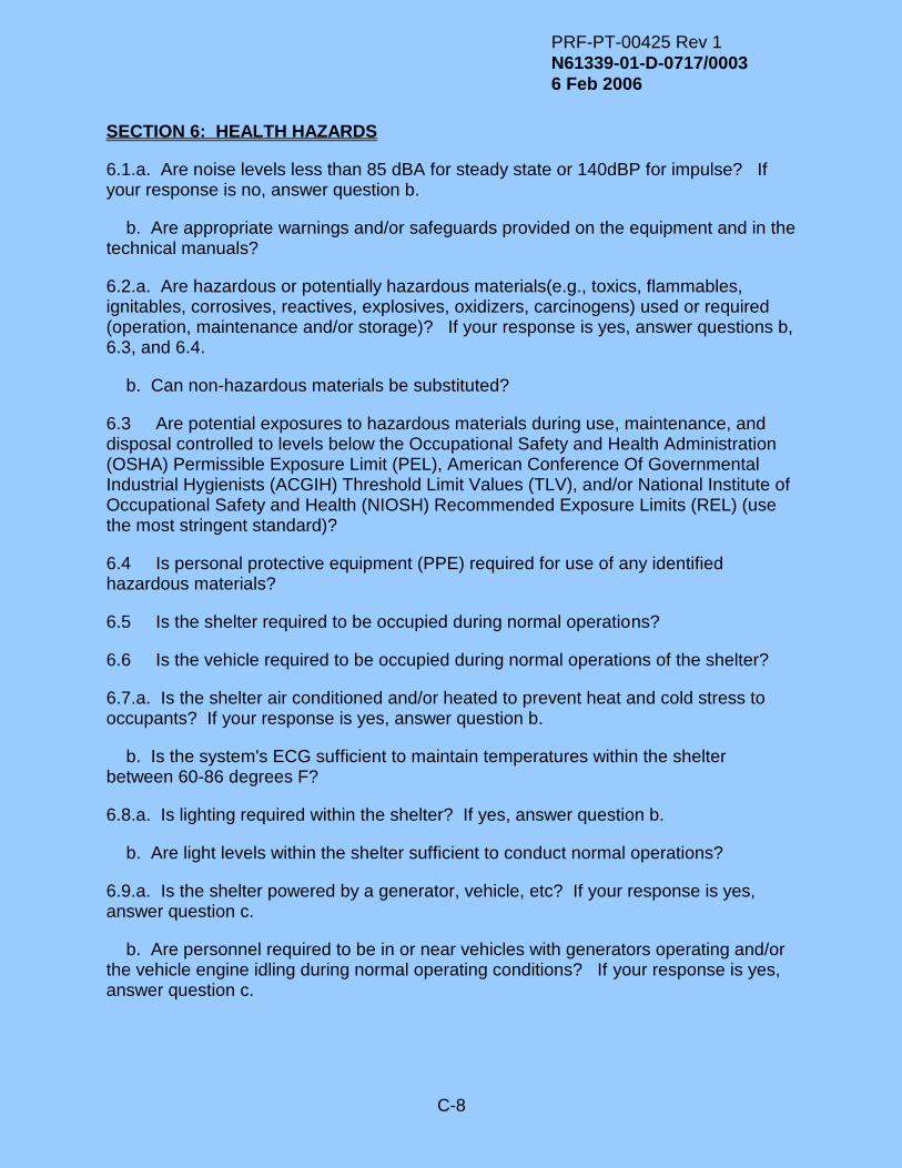
PRF-PT-00425 Rev 1
N61339-01-D-0717/0003
6 Feb 2006
C-8
SECTION 6: HEALTH HAZARDS
6.1.a. Are noise levels less than 85 dBA for steady state or 140dBP for impulse? If your response is no, answer question b.
b. Are appropriate warnings and/or safeguards provided on the equipment and in the technical manuals?
6.2.a. Are hazardous or potentially hazardous materials(e.g., toxics, flammables, ignitables, corrosives, reactives, explosives, oxidizers, carcinogens) used or required (operation, maintenance and/or storage)? If your response is yes, answer questions b, 6.3, and 6.4.
b. Can non-hazardous materials be substituted?
6.3 Are potential exposures to hazardous materials during use, maintenance, and disposal controlled to levels below the Occupational Safety and Health Administration (OSHA) Permissible Exposure Limit (PEL), American Conference Of Governmental Industrial Hygienists (ACGIH) Threshold Limit Values (TLV), and/or National Institute of Occupational Safety and Health (NIOSH) Recommended Exposure Limits (REL) (use the most stringent standard)?
6.4 Is personal protective equipment (PPE) required for use of any identified hazardous materials?
6.5 Is the shelter required to be occupied during normal operations?
6.6 Is the vehicle required to be occupied during normal operations of the shelter?
6.7.a. Is the shelter air conditioned and/or heated to prevent heat and cold stress to occupants? If your response is yes, answer question b.
b. Is the system's ECG sufficient to maintain temperatures within the shelter between 60-86 degrees F?
6.8.a. Is lighting required within the shelter? If yes, answer question b.
b. Are light levels within the shelter sufficient to conduct normal operations?
6.9.a. Is the shelter powered by a generator, vehicle, etc? If your response is yes, answer question c.
b. Are personnel required to be in or near vehicles with generators operating and/or the vehicle engine idling during normal operating conditions? If your response is yes, answer question c.

PRF-PT-00425 Rev 1
N61339-01-D-0717/0003
6 Feb 2006
C-9
c. Do the diesel exhaust levels within the shelter or vehicle exceed permissible limits of the following substances:?
Permissible Limits (PPM)
Substance 8 Hr TWA STEL
Carbon Monoxide 35 200
Formaldehyde 0.75 2
Sulfur Dioxide 2 5
Acrolein 0.1 0.3
Nitric Oxide 25 N/A
Nitrogen Dioxide N/A 1
6.10.a Is insulating material (e.g., asbestos, fibrous glass, mineral wool, polystyrene foam, polyurethane foam) added or incorporated into the shelter, vehicle, or equipment? If your response is yes, answer question b.
b. Are appropriate warnings and/or safeguards provided on the equipment and in the technical manuals?
6.11.a. Are ozone-depleting substances (ODS) (e.g., CFC-11, CFC-12, CFC-113, CFC-114, CFC-115, HCFC-22, HCFC-123, Halon 1211, Halon 1301, Halon 2402, Methyl Chloroform, Carbon Tetrachloride) required? (Clean Air Act). If your response is yes, answer questions b and c.
b. Class 1 ODS can not be used. Are appropriate warnings and/or safeguards provided on the equipment and in the technical manuals?
c. Can substitution with an ozone depletion potential (OPD) of 0.05 or less be used?
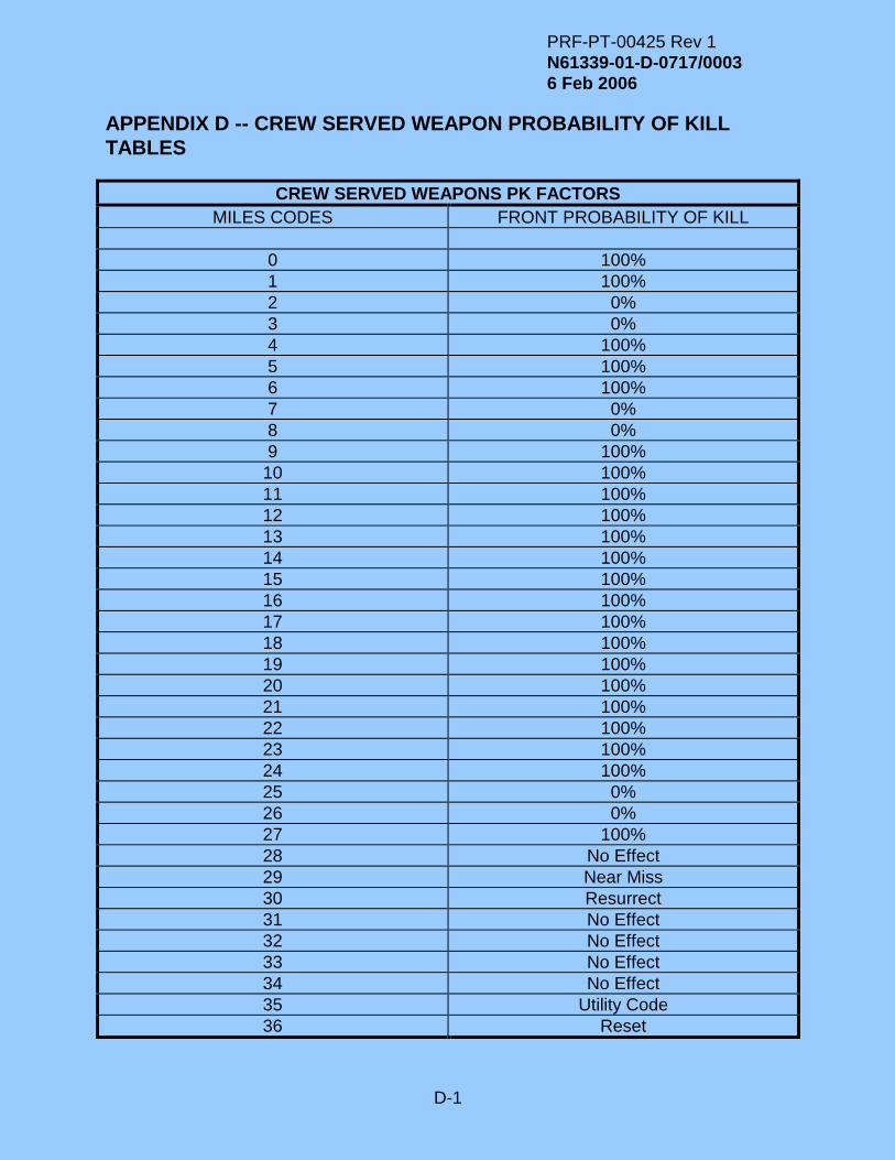
PRF-PT-00425 Rev 1
N61339-01-D-0717/0003
6 Feb 2006
D-1
APPENDIX D -- CREW SERVED WEAPON PROBABILITY OF KILL
TABLES
CREW SERVED WEAPONS PK FACTORS
MILES CODES FRONT PROBABILITY OF KILL
0 100%
1 100%
2 0%
3 0%
4 100%
5 100%
6 100%
7 0%
8 0%
9 100%
10 100%
11 100%
12 100%
13 100%
14 100%
15 100%
16 100%
17 100%
18 100%
19 100%
20 100%
21 100%
22 100%
23 100%
24 100%
25 0%
26 0%
27 100%
28 No Effect
29 Near Miss
30 Resurrect
31 No Effect
32 No Effect
33 No Effect
34 No Effect
35 Utility Code
36 Reset
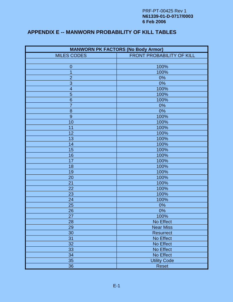
PRF-PT-00425 Rev 1
N61339-01-D-0717/0003
6 Feb 2006
E-1
APPENDIX E -- MANWORN PROBABILITY OF KILL TABLES
MANWORN PK FACTORS (No Body Armor)
MILES CODES FRONT PROBABILITY OF KILL
0 100%
1 100%
2 0%
3 0%
4 100%
5 100%
6 100%
7 0%
8 0%
9 100%
10 100%
11 100%
12 100%
13 100%
14 100%
15 100%
16 100%
17 100%
18 100%
19 100%
20 100%
21 100%
22 100%
23 100%
24 100%
25 0%
26 0%
27 100%
28 No Effect
29 Near Miss
30 Resurrect
31 No Effect
32 No Effect
33 No Effect
34 No Effect
35 Utility Code
36 Reset

PRF-PT-00425 Rev 1
N61339-01-D-0717/0003
6 Feb 2006
E-2
MANWORN PK FACTORS (Body Armor)
MILES CODES FRONT PROBABILITY OF KILL
0 100%
1 100%
2 0%
3 0%
4 100%
5 100%
6 100%
7 0%
8 0%
9 100%
10 100%
11 100%
12 100%
13 100%
14 100%
15 100%
16 100%
17 100%
18 100%
19 100%
20 100%
21 100%
22 100%
23 100%
24 100%
25 0%
26 0%
27 100%
28 No Effect
29 Near Miss
30 Resurrect
31 No Effect
32 No Effect
33 No Effect
34 No Effect
35 Utility Code
36 Reset

PRF-PT-00425 Rev 1
N61339-01-D-0717/0003
6 Feb 2006
E-3