Performance Relighting and Reflectance Transformation...
9
Performance Relighting and Reflectance Transformation with Time-Multiplexed Illumination Andreas Wenger Andrew Gardner Chris Tchou Jonas Unger † Tim Hawkins Paul Debevec University of Southern California Institute for Creative Technologies 1 Figure 1: A live-action performance illuminated several different ways in postproduction. Abstract We present a technique for capturing an actor’s live-action perfor- mance in such a way that the lighting and reflectance of the actor can be designed and modified in postproduction. Our approach is to illuminate the subject with a sequence of time-multiplexed ba- sis lighting conditions, and to record these conditions with a high- speed video camera so that many conditions are recorded in the span of the desired output frame interval. We investigate several lighting bases for representing the sphere of incident illumination using a set of discrete LED light sources, and we estimate and com- pensate for subject motion using optical flow and image warping based on a set of tracking frames inserted into the lighting basis. To composite the illuminated performance into a new background, we include a time-multiplexed matte within the basis. We also show that the acquired data enables time-varying surface normals, albedo, and ambient occlusion to be estimated, which can be used to trans- form the actor’s reflectance to produce both subtle and stylistic ef- fects. CR Categories: I.3.7 [Computer Graphics]: Three-Dimensional Graphics and Realism—Color, shading, shadowing, and texture I.4.8 [Image Processing and Computer Vision]: Digitization and Image Capture—Reflectance I.4.8 [Image Processing and Com- puter Vision]: Scene Analysis—Tracking Keywords: relighting, compositing, environmental illumination, image-based rendering, reflectance models 1 USC ICT, 13274 Fiji Way, Marina del Rey, CA, 90292 Email: [email protected], [email protected], [email protected], [email protected], [email protected], [email protected]. † Supported by the Swedish Research Council and receiving supervisory support from the Swedish National Graduate School in Computer Science. Figure 2: The lighting apparatus used for capturing a performance under time-multiplexed illumination. Behind the actor is the gray background matte surface, and at left is the high-speed camera. 1 Introduction In motion pictures, lighting is not only used to help actors and sets look their best, but as an integral part of storytelling to set mood, direct attention, and underscore performance. This importance is reflected in the high proportion of time and expense spent on light- ing: by many estimates, one half or more [Trumbull 2000] of the valuable time spent on a set is involved in setting up the lighting. Several aspects of film production can be performed after principal photography, such as editing, sound effects, scoring, color timing, and visual effects. In each case, the fact that the process can be per- formed as part of postproduction allows results to be progressively improved and revised by the filmmakers after principal photogra- phy. Lighting, in contrast, must in large part be finalized at the time each scene is filmed. This requirement adds complication and cost to principal photography and provides limited options for modifi- cation and improvement during postproduction. A situation where this is a particularly difficult constraint is when shooting actors in front of a green screen. In this case, the lighting on the actor often must be chosen before the virtual backgrounds are finalized, posing difficulties for achieving consistent illumination between the actors and the background.
Transcript of Performance Relighting and Reflectance Transformation...
Performance Relighting and Reflectance Transformation withTime-Multiplexed Illumination
Andreas Wenger Andrew Gardner Chris Tchou Jonas Unger† Tim Hawkins Paul Debevec
University of Southern California Institute for Creative Technologies1
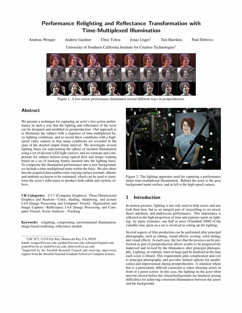
Figure 1: A live-action performance illuminated several different ways in postproduction.
Abstract
We present a technique for capturing an actor’s live-action perfor-mance in such a way that the lighting and reflectance of the actorcan be designed and modified in postproduction. Our approach isto illuminate the subject with a sequence of time-multiplexed ba-sis lighting conditions, and to record these conditions with a high-speed video camera so that many conditions are recorded in thespan of the desired output frame interval. We investigate severallighting bases for representing the sphere of incident illuminationusing a set of discrete LED light sources, and we estimate and com-pensate for subject motion using optical flow and image warpingbased on a set of tracking frames inserted into the lighting basis.To composite the illuminated performance into a new background,we include a time-multiplexed matte within the basis. We also showthat the acquired data enables time-varying surface normals, albedo,and ambient occlusion to be estimated, which can be used to trans-form the actor’s reflectance to produce both subtle and stylistic ef-fects.
CR Categories: I.3.7 [Computer Graphics]: Three-DimensionalGraphics and Realism—Color, shading, shadowing, and textureI.4.8 [Image Processing and Computer Vision]: Digitization andImage Capture—Reflectance I.4.8 [Image Processing and Com-puter Vision]: Scene Analysis—Tracking
Keywords: relighting, compositing, environmental illumination,image-based rendering, reflectance models
1USC ICT, 13274 Fiji Way, Marina del Rey, CA, 90292Email: [email protected], [email protected], [email protected],[email protected], [email protected], [email protected].†Supported by the Swedish Research Council and receiving supervisorysupport from the Swedish National Graduate School in Computer Science.
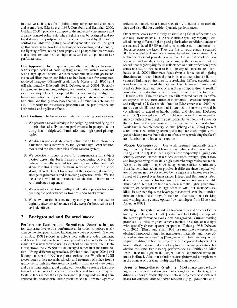
Figure 2: The lighting apparatus used for capturing a performanceunder time-multiplexed illumination. Behind the actor is the graybackground matte surface, and at left is the high-speed camera.
1 Introduction
In motion pictures, lighting is not only used to help actors and setslook their best, but as an integral part of storytelling to set mood,direct attention, and underscore performance. This importance isreflected in the high proportion of time and expense spent on light-ing: by many estimates, one half or more [Trumbull 2000] of thevaluable time spent on a set is involved in setting up the lighting.
Several aspects of film production can be performed after principalphotography, such as editing, sound effects, scoring, color timing,and visual effects. In each case, the fact that the process can be per-formed as part of postproduction allows results to be progressivelyimproved and revised by the filmmakers after principal photogra-phy. Lighting, in contrast, must in large part be finalized at the timeeach scene is filmed. This requirement adds complication and costto principal photography and provides limited options for modifi-cation and improvement during postproduction. A situation wherethis is a particularly difficult constraint is when shooting actors infront of a green screen. In this case, the lighting on the actor oftenmust be chosen before the virtual backgrounds are finalized, posingdifficulties for achieving consistent illumination between the actorsand the background.
Interactive techniques for lighting computer-generated charactersand scenes (e.g. [Marks et al. 1997; Gershbein and Hanrahan 2000;Calahan 2000]) provide a glimpse of the increased convenience andcreative control achievable when lighting can be designed and re-fined during the postproduction process. Inspired by the artisticcontrol available for lighting computer-generated scenes, the goalof this work is to develop a technique for creating and changingthe lighting of live-action photography as a postproduction process,and to demonstrate this technique on several close-up shots of liveperformances.
Our Approach In our approach, we illuminate the performancewith a rapid series of basis lighting conditions which we recordwith a high-speed camera. We then recombine these images to cre-ate novel illumination conditions as has been seen for computer-rendered imagery [Nimeroff et al. 1994; Marks et al. 1997] andstill photography [Haeberli 1992; Debevec et al. 2000]. To applythis process to a moving subject, we develop a motion compen-sation technique based on optical flow to temporally re-align theframes and subsequently reintroduce an appropriate amount of mo-tion blur. We finally show how the basis illumination data can beused to modify the reflectance properties of the performance forboth subtle and stylistic effects.
Contributions In this work we make the following contributions:
1. We present a novel technique for designing and modifying theillumination of a live-action performance in postproductionusing time-multiplexed illumination and high-speed photog-raphy.
2. We discuss and evaluate several illumination bases chosen ina manner that is informed by the system’s light level require-ments and the characteristics of our camera system.
3. We describe a robust process for compensating for subjectmotion across the basis frames by computing optical flowbetween specially inserted tracking frames in the basis. Weshow that this allows the basis sequences to be run moreslowly than the target frame rate of the sequence, decreasingstorage requirements and increasing exposure levels. We usethe same flow fields to introduce realistic motion blur into there-illuminated sequences.
4. We present a novel time-multiplexed matting process for com-positing the performance in front of a new background.
5. We show that the data created by our system can be used todigitally alter the reflectance of the actor for both subtle andstylistic effects.
2 Background and Related Work
Performance Capture and Resynthesis Several techniquesfor capturing live-action performances in order to subsequentlychange the viewpoint and/or lighting have been proposed. [Guenteret al. July 1998] record an actor’s face with five video cameras,and fits a 3D model to facial tracking markers to render the perfor-mance from new viewpoints. In contrast to our work, their tech-nique allows the viewpoint to be changed rather than the illumina-tion. Using different approaches, [Nishino and Nayar 2004] and[Georghiades et al. 1999] use photometric stereo [Woodham 1980]to compute surface normals, albedo, and geometry of a face from asparse set of lighting directions to render it from novel viewpointsand directional lighting, but unlike our work they assume a Lamber-tian reflectance model, do not consider hair, and limit their captureto static faces rather than a performance. [Georghiades 2003] gen-eralized the photometric stereo problem to the Torrance-Sparrow
reflectance model, but assumed specularity to be constant over theface and also did not consider dynamic performances.
Other work looks more closely at simulating facial reflectance ac-curately. [Marschner et al. 2000] estimate spatially-varying facialalbedo using different lighting and polarization conditions and usesa measured facial BRDF model to extrapolate non-Lambertian re-flectance across the face. They use this to texture-map a scanned3D face model and animate it using facial motion capture. Ourtechnique does not provide control over the animation of the per-formance and we do not explore changing the viewpoint, but werecord spatially-varying facial reflectance and interreflection prop-erties and we do not need to build an explicit face model. [De-bevec et al. 2000] illuminate faces from a dense set of lightingdirections and recombines the basis images according to light incaptured lighting environments, reproducing diffuse, specular, andtranslucent reflection of the face and hair. However, their signif-icant capture time and lack of a motion compensation algorithmlimits their investigation to still images of the face in static poses.[Hawkins et al. 2004] use several such illuminated datasets in differ-ent expressions and from different viewpoints to create a morphableand relightable 3D face model, but like [Marschner et al. 2000] re-quires explicit 3D geometry and in contrast to our work would becomplicated to extend to hands, bodies, and clothing. [Debevecet al. 2002] use a sphere of RGB light sources to illuminate perfor-mances with captured lighting environments, but does not allow forthe lighting on the performance to be changed in postproduction.Work that is complementary to ours [Zhang et al. 2004] presenta real-time face scanning technique using stereo and rapidly pro-jected video patterns, but it does not focus on reproducing the face’snon-Lambertian reflectance properties.
Motion Compensation Our work requires temporally align-ing differently illuminated frames in a high-speed video sequence.[Kang et al. 2003] described a system for temporally aligning dif-ferently exposed frames in a video sequence through optical flowand image warping to create a high dynamic range video sequence.We must also align images whose appearance differs significantlyfrom frame to frame, but our problem is different since the pixel val-ues of our images are not related by a single scale factor, even for asubset of the pixel brightness range. [Hager and Belhumeur 1996]described a technique for tracking a face under unknown variableillumination, but did not track motion where the lighting variation,rotation, or occlusion is as significant as what our sequences ex-hibit. In our technique, we leverage our control over the illumina-tion conditions and our high frame rate to facilitate robust trackingand warping using classic optical flow techniques from [Black andAnandan 1993].
Matting Our system includes a time-multiplexed process for ob-taining an alpha channel matte [Porter and Duff 1984] to compositethe actor’s performance over a new background. Current mattingprocesses use blue or green screens behind the actor, or use lightwith specially chosen spectral properties [Fielding 1985; Debevecet al. 2002]. [Smith and Blinn 1996] use multiple backgrounds toobtained improved mattes for transparent materials, and more ad-vanced environment matting [Zongker et al. 1999] techniques canacquire real-time refractive properties of foreground objects. Ourtime-multiplexed matte does not capture refractive properties, butobtains the same transparency performance as [Smith and Blinn1996] since the light on the subject can be suppressed while thematte is filmed. Also, our solution is straightforward to implementin the context of our time-multiplexed lighting system.
Bases for Image-Based Relighting Most image-based relight-ing work has acquired images under single-source lighting con-ditions, although frequently such data is projected onto differentbases for efficient storage and/or rendering (e.g., [Masselus et al.
2004]). [Schechner et al. 2003] suggested using spatially multi-plexed illumination where more than one light source is turned onin each pattern. In our work we implement three different basesranging from single lights to spatially multiplexed illumination.
[Raskar et al. 2004] acquire sequences of people and scenes usingtime-multiplexed flashes placed around the lens of a video cam-era. From the resulting shadows they extracted depth edges to cre-ate a variety of non-photorealistic rendering effects. We also filmthe subject under rapidly changing lighting conditions, but we usehigher frame rates and many more lighting directions to capture de-tailed reflectance information for photorealistic relighting.
Lighting and Reflectance Transformation [Malzbender et al.2001] used a hemispherical lighting apparatus similar to our spher-ical device for capturing images of textures and artifacts under avariety of lighting directions. They fit parabolic polynomials to theacquired reflectance functions, which yielded estimates of the sur-face normals. From the normals, they presented several forms of re-flectance transformation including specular enhancement, where aspecular lobe is added to the reflectance, and diffuse gain, where thewidth of the diffuse component is narrowed to accentuate geometricsurface variation. In our work, we show that similar forms of pro-cessing can be applied to human performances photographed usingour techniques for both subtle and stylized reflectance transforma-tions. Extending this previous work, we use a complete sphere ofincident illumination, and we use a surface normal estimation tech-nique based on photometric stereo that is designed to be robust toself-shadowing and specularities. We also combine the reflectancetransformation process with reflection mapping [Miller and Hoff-man 1984; Greene 1986] to simulate environmental reflection, andwe derive ambient occlusion maps [Landis 2002] for the reflectancefunctions to approximate self-shadowing in the reflection mappingprocess.
Some techniques modify image illumination using a single photo-graph: [Williams 1991] and [Petrovic et al. 2000] use surface nor-mals derived from an “inflation” operation to add novel shading toimages, and [Wen et al. 2003] relight single images of a face withnovel environmental illumination using a fitted generic face model.However, these papers assume simplified reflectance models thathave not been shown to yield photoreal results for extreme changesin incident illumination, for example, taking an input image underharsh lighting and transforming it to diffuse illumination, or vice-versa.
3 Apparatus
Our light stage is a 2m diameter once-subdivided icosahedron, withthe lowest five faces left open to accommodate the actor. A lightsource is placed on each edge and vertex of the stage yielding 156light sources an average of 18◦ apart. Each light source is built fromthree Luxeon V white LEDs which together produce 360 lumens.Each light is focussed toward the subject using a Fraen wide beamtri-lens optic, yielding 420 lux at 1 meter distance. The light is evento within 20% over the area of the actor’s face and shoulders.
A 60 × 40 cm 32% gray board is placed in the back of the structureto obtain the time-multiplexed matte of the actor. To light the board,six additional LED lights are attached to flexible metal arms con-nected to the edges of the board. With just these lights turned on,the actor appears in silhouette against an evenly-illuminated neutralbackground.
We use a Vision Research Phantom v7.1 high-speed digital cam-era capable of capturing up to 4800 frames per second at 800x600resolution. The CMOS sensor is a 12-bit-per-channel single-chipBayer-pattern sensor. The camera records directly to 4GB of inter-nal RAM allowing for 4.3 seconds of capture at a 640×480 cropped
resolution at 2160fps. While expensive, the camera is comparablein cost to current digital motion picture filming equipment.
A Z-World Rabbit 2000 microcontroller drives the lights in arbi-trary pattern sequences and triggers the camera’s shutter in syncwith each pattern. Custom driver boards distributed throughoutthe stage translate TTL signals from a latch board connected tothe microcontroller into the requisite 0.7A current-regulated powerneeded to illuminate the lights.
4 Camera and Light Source Calibration
We calibrated the intensity response curve of the high-speed cam-era by photographing a diffuse white card illuminated by the LEDlights. The LEDs were pulsed at successively longer intervals for100 exposures covering the working range of the sensor. We fit aspline to the response curve, which was close to linear.
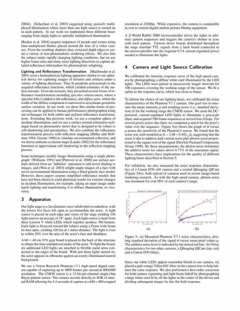
To inform the choice of our lighting bases, we calibrated the noisecharacteristics of the Phantom V7.1 camera. Our goal was to mea-sure the mean intensity µ and resulting noise (i.e., standard devia-tion) σ for the working range the CMOS sensor. We used the DC-powered, current-regulated LED lights to illuminate a grayscalechart, and acquired 100-frame sequences at several lens f/stops. Forseveral pixels across the chart, we computed µ and σ for the pixel’svalue over the sequence. Figure 3(a) shows the graph of σ versusµ across the sensitivity of the Phantom’s sensor. We found that thenoise was well-modeled as σ = 2.68+0.492
õ, suggesting that the
noise is due to additive dark current noise plus photon noise propor-tional to the square root of the signal [Hewlett-Packard ComponentsGroup 1998]. By these measurements, the photon noise dominatesthe additive noise for values above 0.73% of the maximum signal.These characteristics have implications for the quality of differentlighting bases described in Section 5.
For validation, we also measured the noise response characteris-tics of a Canon D30 still camera and a cooled QImaging QICam(Figure 3(b)), both typical of cameras used in recent image-basedrendering research. As with the high-speed camera, photon noisewas dominant for over 98% of each camera’s range.
0 500 1000 1500 2000 2500 3000 3500 40000
5
10
15
20
25
30
35P hantom V 7.1 Noise C haracteris tics
mean [pixel values]
sta
nd
ard
de
via
tion
[p
ixe
l va
lue
s]
0 500 1000 1500 2000 2500 3000 3500 40000
10
20
30
40
50
60
mean [pixel values]
sta
nd
ard
de
via
tion
[p
ixe
l va
lue
s]
C anon D30 and QImaging QIC am F ast Noise C haracteris tics
(a) (b)
Figure 3: (a) Measured Phantom V7.1 noise characteristics, plot-ting standard deviation of the signal σ versus mean pixel values µ.The additive noise level is indicated by the dotted red line. (b) Noisecharacteristics for two other cameras, a QImaging QICam (top, red)and a Canon D30 (blue).
Since our white LEDs appear somewhat bluish to our camera, weplaced a pale orange Tiffen 85C filter on the camera lens to help bal-ance the color response. We also performed a first-order correctionfor both camera vignetting and light beam falloff by photographinga large white card lit by all the lights in the center of the device anddividing subsequent images by this flat field response.

5 Basis Selection
Our microcontroller program can turn on and off any set of lightsources for each frame to produce arbitrary binary patterns. In the-ory, any linearly independent set of patterns equal to the number oflights allows the recovery of the individual lighting directions byinverting a linear system. To design and evaluate bases, we consid-ered three general factors. These included: 1) Subject Perception:whether the lights were too bright or too stroboscopic, 2) ImageQuality: if the recovered lighting resolution is sharp, the imagesexhibit a good signal-to-noise ratio, and if the basis accurately im-ages the dynamic range of diffuse, specular, and shadowed regions,3) Motion Robustness: that the basis is robust to subject motion dur-ing the basis. With these criteria in mind we designed three bases:single lights, triangles of lights, and Hadamard patterns (Figures 4and 6). An exhaustive comparison of the bases is not the focus ofthis paper, but in this section we describe these bases in the contextof our light stage and discuss the advantages and disadvantages thatwe experienced with each.
5.1 Single Light Basis Each of the 156 light sourcesyields 420 lux at the middle of the stage. At our commonly usedframe rate of 2160fps (exposing for 412 of the 462 available mi-croseconds) and at an aperture of f/1.2, this produced pixel values of25% of the saturation level for a 98.5% white reflectance standardand pixel values of 4-8% for diffuse facial reflectance depending onthe subject’s skin tone. At these levels, image noise was somewhatapparent (Figures 6(a,d)), but acceptable relighting results could beobtained when many such images were added together.
Figure 4: Six elements of each of the three lighting bases used inthis work. Top Row: Single lights. Middle Row: Triangles. BottomRow: Hadamard Patterns
5.2 Triangle Basis To increase the illumination, we de-signed a basis using triples of triangularly adjacent lights. For asubdivided icosahedron having a 5-vertex at the top, triangularlyadjacent light groups point toward either the north or the southpole. Taking all triangles pointing toward the north pole yields abasis isomorphic to the single-light basis. For our configuration,this produced a 156-light basis that yielded 1250 lux at the centerof the stage. With this basis, we used the triples of lights as if theywere single individual lighting directions. While this limited theresolution of the lighting environments that could be reproduced,we did not find the effect to be particularly noticeable.
On average, each light source is used in three of the triangle pat-terns. We ordered the triangle sequence so that the times each lightwould turn on were distributed generally evenly in the sequence(Figure 5.) This significantly increased the apparent strobe rate ofeach light.
The triangle basis produced 75% the maximum pixel value whenlighting the white reflectance standard. For diffuse facial re-flectance, the pixel values were approximately 12-24% of this max-imum. We found this light level to be nearly optimal, since it pro-vided room in the response for brighter areas such as the teeth andwhites of the eye, and it allowed most of the specular reflections tobe imaged within the range of the sensor.
5.3 Hadamard Basis [Schechner et al. 2003] suggest us-ing patterns based on Hadamard matrices to construct an illumina-tion basis for image-based relighting of static scenes. A related pro-cess is commonly used in spectroscopy [Harwit and Sloane 1979] toincrease the signal to noise ratios of spectral measurements. In thistechnique, there are k basis patterns, where k is an odd number. Ineach pattern, just over half of the lights are on, and across the basiseach light is on in precisely (k +1)/2 of the patterns. The patternsare constructed so that one can recover an image of the subject illu-minated by a single light, i.e. invert the basis, by adding the imagestaken when the light is on and subtracting the images taken whenthe light is off; all other light contributions cancel. In our work weused a 156×156 Hadamard matrix [Sloan 1999] which is based onthe Williamson construction [Hall 1998].
If a sensor obeys an additive noise model, [Schechner et al. 2003]note that there will be an advantage of increased signal to noise ratioin the recovered images. For example, if there is additive noisewith standard deviation σ in each image and k basis images aretaken, the recovery process adds and subtracts k images yielding atotal noise of σ
√k. If a pixel appears illuminated with brightness
L in each image, then its brightness in the recovered sum will beL(k + 1)/2. Thus, the signal to noise ratio increases from L/σ toL(k +1)/(2σ
√k), an increase of approximately
√k
2 .
Unfortunately, the geometry of our apparatus and the noise re-sponse of our camera are different than those assumed in [Schech-ner et al. 2003]. Since our lights are distributed on a completesphere, half of the lights typically make little or no contributionto a given pixel’s intensity. For those that do, their irradiance isgenerally attenuated by Lambertian cosine falloff, which averagesto a factor of 1
2 over the hemisphere. Thus, our expected signal tonoise ratio decreases by a factor of four to 1
4 L(k + 1)/(2σ√
k), anSNR gain of 1
8
√k. For our particular case of k = 156, this would
yield only a modest 56% SNR increase.
Another impediment to an SNR improvement is that our camera’snoise is dominated by photon noise over 98% of its exposure rangeas seen in Figure 3(a). In this region, the photon noise proportionalto the square root of the signal counteracts the O(
√k) SNR gain of
the additive noise model. Since we have sufficient light to operatein this region with single light sources, we would not expect anSNR gain from using the Hadamard basis.
We did notice that the Hadamard patterns significantly increasedthe average light output of the device. At an aperture of f/1.2, itwas necessary to reduce the exposure interval to 100 µs per patternin order to avoid saturating the sensor. We chose to reduce theexposure interval rather than narrow the aperture since this reducedthe light on the performer to a more comfortable level, from 6600 to1600 lux (A bright cloudy sky is approximately 5000 lux, so 6600lux can seem bright when projected indoors.) We could alternatelyhave narrowed the aperture to f/2.8, an iris setting commonly usedfor filming motion pictures, to increase the depth of field.
5.4 Basis Comparison Figure 6 shows a comparison theindividual lighting directions derived from the three bases.
Subject Perception The performers were screened for any med-ical history of adverse reactions to blinking lights and asked to no-tify the operators immediately of any discomfort. None of the per-formers or members of our laboratory reported an adverse reactionto any of the bases. The Hadamard patterns produced the least per-ceptible strobing, but performers who had adapted to dim interiorlighting noted that the basis was relatively bright. The single lightswere the most stroboscopic, but relatively dim. The triangle basiswas moderately stroboscopic and moderately bright.

Figure 5: Successive images of an actor lit by the 180-pattern sequence in the span of one twelfth of a second. Tracking and matte framesseen in the two left columns occur ten times each within the lighting basis with an effective rate of 120Hz in the 2160fps sequence.
Image Quality We tested the effective signal to noise ratio ofthe three bases by capturing 100 successive basis sequences of agreyscale chart placed in the apparatus. For several pixels on thepatch corresponding to average skin reflectance, we computed thesignal-to-noise ratio (SNR) over the 100-image sequence. The av-erage of these SNRs is tabulated below:
Single Triangle Hadamardmean µ 613 1327 2015
std dev σ 13.5 16.4 50.2SNR 45.4 80.9 40.1
The single light images exhibited greater noise than the trianglebasis due to the lower light levels. We found that the recoveredsingle-light images from the Hadamard basis exhibited a slightlyworse SNR than the single lights. However, in shadowed regions,the Hadamard patterns produced significantly greater noise than thesingle lights as seen in comparing Figure 6(d) to Figure 6(f). This isbecause these shadowed regions are generally not shadowed in theoriginal Hadamard basis images and thus exhibit the increased pho-ton noise of the larger signal. The triangle basis images producedthe best SNR, but it is important to note that this is not a directcomparison since this basis can not resolve as detailed a lightingresolution as either the single lights or the Hadamard patterns. Ifwe were to simulate the triangle basis by adding together triples ofsingle light images or recovered Hadamard directions, their SNRwould increase by
√3 and in each case become much closer to the
SNR of the triangle basis, at least for non-shadowed regions.
For our subjects, none of the basis patterns produced significantproblems with specularities, except at extreme grazing angles onthe skin and in the reflections of the eyes.
Motion Robustness The recovered single-light directions fromthe Hadamard patterns occasionally exhibited banding from sub-ject motion during the basis since they are formed as nonconvexlinear combinations of images taken of a moving subject. The prob-lem was substantially reduced when the motion compensation tech-niques described in Sec. 6 were applied, but were still occasionallyvisible in regions such as eyelid blinks. Neither the single lightnor triangle bases exhibited this effect since no basis inversion isrequired.
For our camera, lighting apparatus, and subjects, we found that thetriangle basis provided a reasonable compromise between subjectperception, lighting resolution, and image quality. The Hadamardpatterns did not yield an improved SNR for our camera and lightingconfiguration, though they did show the potential to better captureobject specularities and to minimize strobing. For systems withdifferent cameras, lights, or lighting resolution requirements, theadvantage could be more significant, and further explorations intothe space of lighting bases could be fruitful.
(a) (b) (c)
(d) (e) (f)
Figure 6: Directional lighting basis frames and detail areas from(a,d) the single light basis, (b,e) the triangle basis, (c,f) theHadamard basis. For (c,f), the image was recovered as a linearcombination of all 155 basis patterns.
6 Motion Compensation
Although we film the actor at a high frame rate, the actor’s motionacross a full basis sequence can be significant. When these basisimages are added together, this can lead to an image smearing ef-fect in the re-illuminated frames as seen in Figure 8(a). For diffuselighting, the effect is similar to exaggerated motion blur, but whenlight intensities in the environment correlate with the ordering ofthe basis, different areas of the face will experience different spa-tiotemporal displacements, which can appear objectionable.
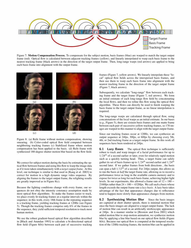
Target FrameBasis FrameTracking Frame
Figure 7: Motion Compensation Process. To compensate for the subject motion, basis frames (blue) are warped to match the target outputframe (red). Optical flow is calculated between adjacent tracking frames (yellow), and linearly interpolated to warp each basis frame to thenearest tracking frame (black arrows) in the direction of the target output frame. Then, long-range warps (red arrows) are applied to bringeach basis frame into alignment with the output frame.
(a) (b)
(c) (d)
Figure 8: (a) Relit frame without motion compensation, showingsmearing. (b) Color-coded optical flow field computed betweenneighboring tracking frames (c) Stabilized frame where motioncompensation has been applied to the basis. (d) Relit frame withsynthesized 180-degree shutter motion blur based on the flow field.
We correct for subject motion during the basis by estimating the op-tical flow between frames and using this flow to warp the image dataas if it were taken simultaneously with a target output frame. At thislevel, our technique is similar to that used in [Kang et al. 2003] tocorrect for motion in a high dynamic range video sequence. Byaligning the frames to the target output frame, the relighting resultsare greatly improved as in Figure 8(c).
Because the lighting conditions change with every frame, our se-quences do not obey the intensity constancy assumption made bymost optical flow algorithms. To make the frames easier to track,we place evenly lit tracking frames at a regular intervals within thesequence; in this work, every 18th frame in the repeating sequenceis a tracking frame, yielding tracking frames at 120Hz (see Figure5). Though the tracking frames comprise only 6% of the frames inthe sequence, they yield sufficient temporal resolution to track mosthuman motion.
We use the robust gradient-based optical flow algorithm describedin [Black and Anandan 1993] to calculate a bi-directional opticalflow field (Figure 8(b)) between each pair of successive tracking
frames (Figure 7, yellow arrows). We linearly interpolate these “lo-cal” optical flow fields across the interspersed basis frames, andthen use them to warp each basis frame into alignment with thenearest tracking frame in the direction of the target output frame(Figure 7, black arrows).
Subsequently, we calculate “long-range” flow between each track-ing frame and the target frame (Figure 7, red arrows). We forman initial estimate of each long-range flow field by concatenatingthe local flows, and then we refine this flow using the optical flowalgorithm. These flows can directly be used to finish warping thebasis frame to the target output frame, as no linear interpolation isrequired.
The long-range warps are calculated through optical flow, usingconcatenations of the local warps as an initial estimate. In our bases(e.g., Figure 5), there are sixteen basis frames and one matte framebetween each pair of successive yellow tracking frames, so 170 im-ages are warped in this manner to align with the target output frame.
Since our tracking frames occur at 120Hz, we can synthesize anoutput sequence at 24fps, 30fps, or 60fps by choosing every 5th,4th, or 2nd tracking frame as a target output frame. In this work allsequences have been rendered at 24fps.
6.1 Lazy Bases The optical flow technique is sufficientlyrobust to track and warp images of a facial performance for up to1/24th of a second earlier or later, even for relatively rapid motionsuch as a quickly turning head. Thus, a target frame can safelygather its set of basis frames up to 1/24th second earlier and 1/24th
second later. If we gather frames from both directions , the basiscan span a full 1/12th of a second. For 24fps output, this allows usto run the basis at half the target frame rate, allowing us to record aperformance twice as long in the available camera memory and toexpose for twice as long for each basis frame, achieving higher lightlevels. In our experiments, this allowed a frame rate of 12×180 =2160fps rather than 24×180 = 4320fps. We call such a basis whoselength exceeds the output frame rate a lazy basis. A lazy basis takesadvantage of the fact that appearance changes due to reflectancetend to happen more slowly than appearance changes from motion.
6.2 Synthesizing Motion Blur Since the basis imagesare captured at short shutter speeds, there is minimal motion bluronce the basis images are aligned to a target output frame. The lackof motion blur can result in an artificially stroboscopic appearanceat 24fps. In a manner similar to [Brostow and Essa 2001] whichadded motion blur to stop-motion animation, we synthesize motionblur by applying a line blur based on our optical flow fields (Figure8(b)). Because our optical flow is computed at the temporal resolu-tion of the 120Hz tracking frames, the motion blur can be applied in
a piecewise linear manner, producing a more accurate blur profilethat can exhibit curves and accelerations in the 24fps output. Weimproved our results by using modified Wu anti-aliased lines [Wu1991], yielding a somewhat smoother result than the line algorithmin [Brostow and Essa 2001].
7 Matting
We include a matte frame after each tracking frame in the lightingsequence (see Figure 5) in which the board behind the subject isilluminated by its own light sources. This yields an image of theshadowed subject against the brightly lit board. After filming thesubject, we acquire a ”clean plate” of the board for one cycle of thefull pattern sequence. Dividing each pixel in a matte frame by theclean plate’s average matte frame produces an alpha matte imagewhere α = 0 represents the foreground and α = 1 represents thebackground. Since there is a matte frame for each tracking frame,we reduce noise in the matte by using a weighted average of theten closest matte frames to the target output frame. Like the basisimages, the matte frames are also motion compensated to align witheach other.
Since the matte board receives some stray light in many of the basisframes (see Figure 5.), we use the appearance of the stray light inthe clean plate to remove the stray light from the basis images ofthe actor. Specifically, for a basis image F and corresponding cleanplate image C, we compute F ′ = F −αC to matte the basis imageonto black, clamping any negative values to zero. Then, after thesebasis images are recombined to produce a relit image of the actorL, we composite L over a background B using the [Porter and Duff1984] “over” operator I f inal = L+αB. We found that this techniqueproduced good matte edges, but note that a rear-projected matteboard with low frontal albedo could reduce the problem of straylight.
8 Reflectance Transformation
Following [Malzbender et al. 2001], we can modify both the dif-fuse and specular reflectance of a performance by processing thereflectance functions. Our reflectance functions are 156-pixel im-ages corresponding to the observed RGB value of a pixel of theperformance lit by each lighting direction.
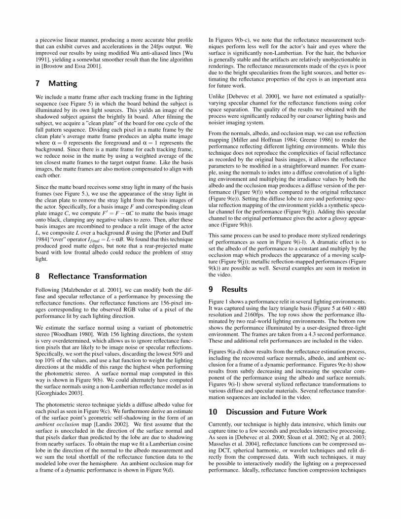
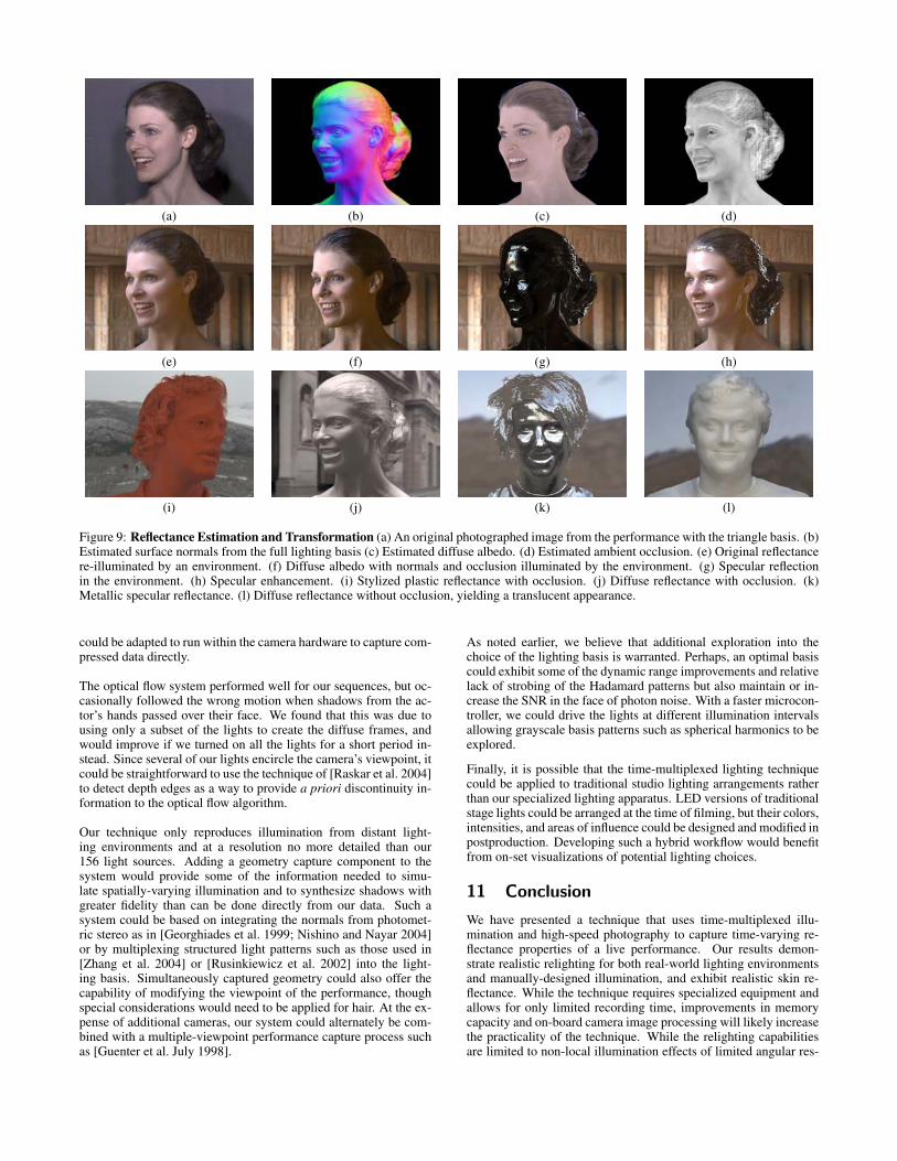
We estimate the surface normal using a variant of photometricstereo [Woodham 1980]. With 156 lighting directions, the systemis very overdetermined, which allows us to ignore reflectance func-tion pixels that are likely to be image noise or specular reflections.Specifically, we sort the pixel values, discarding the lowest 50% andtop 10% of the values, and use a hat function to weight the lightingdirections at the middle of this range the highest when performingthe photometric stereo. A surface normal map computed in thisway is shown in Figure 9(b). We could alternately have computedthe surface normals using a non-Lambertian reflectance model as in[Georghiades 2003].
The photometric stereo technique yields a diffuse albedo value foreach pixel as seen in Figure 9(c). We furthermore derive an estimateof the surface point’s geometric self-shadowing in the form of anambient occlusion map [Landis 2002]. We first assume that thesurface is unoccluded in the direction of the surface normal andthat pixels darker than predicted by the lobe are due to shadowingfrom nearby surfaces. To obtain the map we fit a Lambertian cosinelobe in the direction of the normal to the albedo measurement andwe sum the total shortfall of the reflectance function data to themodeled lobe over the hemisphere. An ambient occlusion map fora frame of a dynamic performance is shown in Figure 9(d).
In Figures 9(b-c), we note that the reflectance measurement tech-niques perform less well for the actor’s hair and eyes where thesurface is significantly non-Lambertian. For the hair, the behavioris generally stable and the artifacts are relatively unobjectionable inrenderings. The reflectance measurements made of the eyes is poordue to the bright specularities from the light sources, and better es-timating the reflectance properties of the eyes is an important areafor future work.
Unlike [Debevec et al. 2000], we have not estimated a spatially-varying specular channel for the reflectance functions using colorspace separation. The quality of the results we obtained with theprocess were significantly reduced by our coarser lighting basis andnoisier imaging system.
From the normals, albedo, and occlusion map, we can use reflectionmapping [Miller and Hoffman 1984; Greene 1986] to render theperformance reflecting different lighting environments. While thistechnique does not reproduce the complexities of facial reflectanceas recorded by the original basis images, it allows the reflectanceparameters to be modified in a straightforward manner. For exam-ple, using the normals to index into a diffuse convolution of a light-ing environment and multiplying the irradiance values by both thealbedo and the occlusion map produces a diffuse version of the per-formance (Figure 9(f)) when compared to the original reflectance(Figure 9(e)). Setting the diffuse lobe to zero and performing spec-ular reflection mapping of the environment yields a synthetic specu-lar channel for the performance (Figure 9(g)). Adding this specularchannel to the original performance gives the actor a glossy appear-ance (Figure 9(h)).
This same process can be used to produce more stylized renderingsof performances as seen in Figure 9(i-l). A dramatic effect is toset the albedo of the performance to a constant and multiply by theocclusion map which produces the appearance of a moving sculp-ture (Figure 9(j)); metallic reflection-mapped performances (Figure9(k)) are possible as well. Several examples are seen in motion inthe video.
9 Results
Figure 1 shows a performance relit in several lighting environments.It was captured using the lazy triangle basis (Figure 5 at 640×480resolution and 2160fps. The top rows show the performance illu-minated by two real-world lighting environments. The bottom rowshows the performance illuminated by a user-designed three-lightenvironment. The frames are taken from a 4.3 second performance.These and additional relit performances are included in the video.
Figures 9(a-d) show results from the reflectance estimation process,including the recovered surface normals, albedo, and ambient oc-clusion for a frame of a dynamic performance. Figures 9(e-h) showresults from subtly decreasing and increasing the specular com-ponent of the performance using the albedo and surface normals.Figures 9(i-l) show several stylized reflectance transformations tovarious diffuse and specular materials. Several reflectance transfor-mation sequences are included in the video.
10 Discussion and Future Work
Currently, our technique is highly data intensive, which limits ourcapture time to a few seconds and precludes interactive processing.As seen in [Debevec et al. 2000; Sloan et al. 2002; Ng et al. 2003;Masselus et al. 2004], reflectance functions can be compressed us-ing DCT, spherical harmonic, or wavelet techniques and relit di-rectly from the compressed data. With such techniques, it maybe possible to interactively modify the lighting on a preprocessedperformance. Ideally, reflectance function compression techniques
(a) (b) (c) (d)
(e) (f) (g) (h)
(i) (j) (k) (l)
Figure 9: Reflectance Estimation and Transformation (a) An original photographed image from the performance with the triangle basis. (b)Estimated surface normals from the full lighting basis (c) Estimated diffuse albedo. (d) Estimated ambient occlusion. (e) Original reflectancere-illuminated by an environment. (f) Diffuse albedo with normals and occlusion illuminated by the environment. (g) Specular reflectionin the environment. (h) Specular enhancement. (i) Stylized plastic reflectance with occlusion. (j) Diffuse reflectance with occlusion. (k)Metallic specular reflectance. (l) Diffuse reflectance without occlusion, yielding a translucent appearance.
could be adapted to run within the camera hardware to capture com-pressed data directly.
The optical flow system performed well for our sequences, but oc-casionally followed the wrong motion when shadows from the ac-tor’s hands passed over their face. We found that this was due tousing only a subset of the lights to create the diffuse frames, andwould improve if we turned on all the lights for a short period in-stead. Since several of our lights encircle the camera’s viewpoint, itcould be straightforward to use the technique of [Raskar et al. 2004]to detect depth edges as a way to provide a priori discontinuity in-formation to the optical flow algorithm.
Our technique only reproduces illumination from distant light-ing environments and at a resolution no more detailed than our156 light sources. Adding a geometry capture component to thesystem would provide some of the information needed to simu-late spatially-varying illumination and to synthesize shadows withgreater fidelity than can be done directly from our data. Such asystem could be based on integrating the normals from photomet-ric stereo as in [Georghiades et al. 1999; Nishino and Nayar 2004]or by multiplexing structured light patterns such as those used in[Zhang et al. 2004] or [Rusinkiewicz et al. 2002] into the light-ing basis. Simultaneously captured geometry could also offer thecapability of modifying the viewpoint of the performance, thoughspecial considerations would need to be applied for hair. At the ex-pense of additional cameras, our system could alternately be com-bined with a multiple-viewpoint performance capture process suchas [Guenter et al. July 1998].
As noted earlier, we believe that additional exploration into thechoice of the lighting basis is warranted. Perhaps, an optimal basiscould exhibit some of the dynamic range improvements and relativelack of strobing of the Hadamard patterns but also maintain or in-crease the SNR in the face of photon noise. With a faster microcon-troller, we could drive the lights at different illumination intervalsallowing grayscale basis patterns such as spherical harmonics to beexplored.
Finally, it is possible that the time-multiplexed lighting techniquecould be applied to traditional studio lighting arrangements ratherthan our specialized lighting apparatus. LED versions of traditionalstage lights could be arranged at the time of filming, but their colors,intensities, and areas of influence could be designed and modified inpostproduction. Developing such a hybrid workflow would benefitfrom on-set visualizations of potential lighting choices.
11 Conclusion
We have presented a technique that uses time-multiplexed illu-mination and high-speed photography to capture time-varying re-flectance properties of a live performance. Our results demon-strate realistic relighting for both real-world lighting environmentsand manually-designed illumination, and exhibit realistic skin re-flectance. While the technique requires specialized equipment andallows for only limited recording time, improvements in memorycapacity and on-board camera image processing will likely increasethe practicality of the technique. While the relighting capabilitiesare limited to non-local illumination effects of limited angular res-
olution, the technique holds promise as a novel and useful tool forfilmmakers wishing to modify live-action lighting in postproduc-tion.
Acknowledgements
The authors wish to thank Marissa Sellers (Figure 1), Charles-Felix Chabert (Figure 8), Elizabeth Franklin (Figure 9), JohanToerne (Figure 9(l)), John Biondo, Mark Ollila, Maya Martinez,John Lai, Andrew Jones, Laurie Swanson, Peter James, MarkBolas, Tom Pereira, Lora Chen, Krishna Mamidibathula, LarryVladic, Mark Gangi, Tony Lucatorto, Paul Laureano, Vision Re-search, Inc., Alexander Singer, Randal Kleiser, Bill Swartout,David Wertheimer, and Neil Sullivan for their support and assis-tance with this work. This work was sponsored by the Universityof Southern California Office of the Provost and the U.S. ArmyResearch, Development, and Engineering Command (RDECOM).The content of the information does not necessarily reflect the po-sition or the policy of the US Government, and no official endorse-ment should be inferred.
ReferencesBLACK, M. J., AND ANANDAN, P. 1993. A framework for the robust estimation of
optical flow. In Fourth International Conf. on Computer Vision, 231–236.
BROSTOW, G. J., AND ESSA, I. 2001. Image-based motion blur for stop motionanimation. In Proceedings of ACM SIGGRAPH 2001, Computer Graphics Pro-ceedings, Annual Conference Series, 561–566.
CALAHAN, S. 2000. Advanced Renderman: Creating CGI for Motion Pictures. Mor-gan Kaufman Publishers, San Francisco, ch. Storytelling through lighting, a com-puter perspective, 337382.
DEBEVEC, P., HAWKINS, T., TCHOU, C., DUIKER, H.-P., SAROKIN, W., AND
SAGAR, M. 2000. Acquiring the reflectance field of a human face. Proceedings ofSIGGRAPH 2000 (July), 145–156.
DEBEVEC, P., WENGER, A., TCHOU, C., GARDNER, A., WAESE, J., AND
HAWKINS, T. 2002. A lighting reproduction approach to live-action composit-ing. ACM Transactions on Graphics 21, 3 (July), 547–556.
FIELDING, R. 1985. The Technique of Special Effects Cinematography, 4th ed. Hast-ings House, New York.
GEORGHIADES, A., BELHUMEUR, P., AND KRIEGMAN, D. 1999. Illumination-based image synthesis: Creating novel images of human faces under differing poseand lighting. In IEEE Workshop on Multi-View Modeling and Analysis of VisualScenes, 47–54.
GEORGHIADES, A. S. 2003. Recovering 3-d shape and reflectance from a small num-ber of photographs. In Eurographics Symposium on Rendering: 14th EurographicsWorkshop on Rendering, 230–240.
GERSHBEIN, R., AND HANRAHAN, P. M. 2000. A fast relighting engine for in-teractive cinematic lighting design. In Proceedings of ACM SIGGRAPH 2000,Computer Graphics Proceedings, Annual Conference Series, 353–358.
GREENE, N. 1986. Environment mapping and other application of world projections.IEEE Computer Graphics and Applications 6, 11 (November), 21–29.
GUENTER, B., GRIMM, C., WOOD, D., MALVAR, H., AND PIGHIN, F. July 1998.Making faces. Proceedings of SIGGRAPH 98, 55–66.
HAEBERLI, P. 1992. Synthetic lighting for photography. Available athttp://www.sgi.com/grafica/synth/index.html, January.
HAGER, G. D., AND BELHUMEUR, P. N. 1996. Real-time tracking of image regionswith changes in geometry and illumination. In Proc. IEEE Conf. on Comp. Visionand Patt. Recog., 403–410.
HALL, M. 1998. Combinatorial Theory, 2nd ed. Wiley, New York.
HARWIT, M., AND SLOANE, N. J. A. 1979. Hadamard transform optics. AcademicPress, New York.
HAWKINS, T., WENGER, A., TCHOU, C., AND DEBEVEC, A. G. F. G. P. 2004.Animatable facial reflectance fields. In Eurographics Symposium on Rendering:15th Eurographics Workshop on Rendering.
HEWLETT-PACKARD COMPONENTS GROUP. 1998. Noise sources in cmos imagesensors. Tech. rep., Hewlett-Packard.
KANG, S. B., UYTTENDAELE, M., WINDER, S., AND SZELISKI, R. 2003. Highdynamic range video. ACM Transactions on Graphics 22, 3 (July), 319–325.
LANDIS, H., 2002. Production-ready global illumination. Course Notes for SIG-GRAPH 2002 Course 16, RenderMan in Production.
MALZBENDER, T., GELB, D., AND WOLTERS, H. 2001. Polynomial texture maps.Proceedings of SIGGRAPH 2001 (August), 519–528.
MARKS, J., ANDALMAN, B., BEARDSLEY, P. A., FREEMAN, W., GIBSON, S.,HODGINS, J. K., KANG, T., MIRTICH, B., PFISTER, H., RUML, W., RYALL,K., SEIMS, J., AND SHIEBER, S. 1997. Design galleries: A general approach tosetting parameters for computer graphics and animation. In Proceedings of SIG-GRAPH 97, Computer Graphics Proceedings, Annual Conference Series, 389–400.
MARSCHNER, S., GUENTER, B., AND RAGHUPATHY, S. 2000. Modeling and ren-dering for realistic facial animation. In Rendering Techniques 2000: 11th Euro-graphics Workshop on Rendering, 231–242.
MASSELUS, V., PEERS, P., DUTRE, P., AND WILLEMS, Y. D. 2004. Smooth re-construction and compact representation of reflectance functions for image-basedrelighting. In 15th Eurographics Symposium on Rendering, no. Norrkoping, Swe-den.
MILLER, G. S., AND HOFFMAN, C. R. 1984. Illumination and reflection maps:Simulated objects in simulated and real environments. In SIGGRAPH 84 CourseNotes for Advanced Computer Graphics Animation.
NG, R., RAMAMOORTHI, R., AND HANRAHAN, P. 2003. All-frequency shadowsusing non-linear wavelet lighting approximation. ACM Transactions on Graphics22, 3 (July), 376–381.
NIMEROFF, J. S., SIMONCELLI, E., AND DORSEY, J. 1994. Efficient re-rendering ofnaturally illuminated environments. In Fifth Eurographics Workshop on Rendering,359–373.
NISHINO, K., AND NAYAR, S. K. 2004. Eyes for relighting. ACM Transactions onGraphics 23, 3 (Aug.), 704–711.
PETROVIC, L., FUJITO, B., WILLIAMS, L., AND FINKELSTEIN, A. 2000. Shadowsfor cel animation. In Proceedings of ACM SIGGRAPH 2000, Computer GraphicsProceedings, Annual Conference Series, 511–516.
PORTER, T., AND DUFF, T. 1984. Compositing digital images. In Computer Graphics(Proceedings of SIGGRAPH 84), vol. 18, 253–259.
RASKAR, R., TAN, K.-H., FERIS, R., YU, J., AND TURK, M. 2004. Non-photorealistic camera: depth edge detection and stylized rendering using multi-flash imaging. ACM Transactions on Graphics 23, 3 (Aug.), 679–688.
RUSINKIEWICZ, S., HALL-HOLT, O., AND LEVOY, M. 2002. Real-time 3d modelacquisition. ACM Transactions on Graphics 21, 3 (July), 438–446.
SCHECHNER, Y. Y., NAYAR, S. K., AND BELHUMEUR, P. 2003. A theory of multi-plexed illumination. In International Conference on Computer Vision.
SLOAN, P.-P., KAUTZ, J., AND SNYDER, J. 2002. Precomputed radiance transferfor real-time rendering in dynamic, low-frequency lighting environments. ACMTransactions on Graphics 21, 3 (July), 527–536.
SLOAN, N. J. A., 1999. A library of hadamard matrices.http://www.research.att.com/˜njas/hadamard/.
SMITH, A. R., AND BLINN, J. F. 1996. Blue screen matting. In Proceedings ofSIGGRAPH 96, 259–268.
TRUMBULL, D. 2000. Personal communication. January.
WEN, Z., LIU, Z., AND HUANG, T. S. 2003. Face relighting with radiance envi-ronment maps. In 2003 Conference on Computer Vision and Pattern Recognition(CVPR 2003), 158–165.
WILLIAMS, L. 1991. Shading in two dimensions. In Graphics Interface ’91, 143–151.
WOODHAM, R. J. 1980. Photometric method for determining surface orientation frommultiple images. Optical Engineering 19, 1, 139–144.
WU, X. 1991. An efficient antialiasing technique. In SIGGRAPH 91: Proceedingsof the 18th annual conference on Computer graphics and interactive techniques,ACM Press, 143–152.
ZHANG, L., SNAVELY, N., CURLESS, B., AND SEITZ, S. M. 2004. Spacetimefaces: high resolution capture for modeling and animation. ACM Transactions onGraphics 23, 3 (Aug.), 548–558.
ZONGKER, D. E., WERNER, D. M., CURLESS, B., AND SALESIN, D. H. 1999.Environment matting and compositing. Proceedings of SIGGRAPH 99 (August),205–214.