Performance of Steel Structures During the 1994 Northridge Earthquake
23
Performance of steel structures during the 1994 Northridge earthquake Robert Tremblay Peter Timle r Michel Bruneau and Andre Filiatrault Abstract: The performance of concentrically braced steel frames and moment resisting steel frames during the January 17, 1994, Northridge, California, earthquake is examined. Most of the observations made during the reconnaissance visits confirmed the current knowledge on the inelastic response of these structural systems. This permits the anticipation of proper seismic behavior for buildings designed according to the seismic provisions that have been recently introduced in the Canadian building code and standard for steel structures. In some cases, however, the observed damage raised concerns that should be addressed in future investigations or next editions of these codes. Preventing potentially hazardous nonstructural damage, avoiding premature nonductile failures anywhere along the lateral load paths, limiting structural and nonstructural damage due to brace buckling, and accounting for the vertical ground motion are among those issues. Key words arthquake, seismic, steel, concentrically braced frames, moment resisting frames, weld. R um Dans cet article, on examine et commente le comportement de charpentes mCtalliques avec contreventement en treillis ou cadres rigides lors du stisme qui a eu lieu le 17 janvier 1994 5 Northridge, en Californie. La majorit6 des observations faites lors des visites effectuCes sur le site confirment les connaissances dCji acquises sur le comportement non lintaire de ces systbmes structuraux lorsque soumis aux stismes. Ceci permet de croire que les bitiments conGus selon les dispositions sCismiques nouvellement introduites dans le code du bitiment canadien et la norme canadienne pour la calcul des structures d acier seront adCquats dans 1 CventualitC de tremblements de terre importants. Dans certains cas, cependant, les dommages subis soulbvent des interrogations qui devraient faire l objet d Ctudes futures en vue dlamCliorer ces normes. Parmi les points qui devraient Ctre examinks, on retrouve la prCvention des dommages non-structuraux 5 risque, la prevention de ruptures subites et non-ductiles le long du cheminement des efforts induits par les charges latCrales, la rkduction des dommages imposCes aux ClCments structuraux ou non-structuraux lors du flambement des membrures diagonales des contreventements ainsi que la prise en compte des effets des mouvements verticaux du sol. Mots clb tremblement de terre, sCisme, charpentes mttalliques, contreventement en treillis, cadre rigide, soudure. Introduction ties were attributed to unsatisfactory performance of steel The earthquake resistance of steel frames has been known to be tremendously reliable overall, with steel building col- lapses so far bei ng the rare occurrence worldwide (Yanev et al. 199 1). In the January, 1994, Northridge earthquake, steel frames also sustained well the ground shaking, as no fatali- Received June 16, 1994. Revised manuscript accepted December 22, 1994. R. Tremblay an d A. Filiatrault. Department of Civil Engineering, Ecole polytechnique, Montreal, QC H3C 3A7, Canada. P. Timler. Sandwell Inc., Engineering and Construction Services Group, 1190 Hornby Street, Vancouver, BC V6Z 2H6, Canada. Bruneau. Ottawa-Carleton Earthquake Engineering Research Center, Department of Civil Engineering, Universitv of Ottawa. Ottawa. ON K1N 6N 5. Canada. structures and no collapses of steel bufidings were reported (AISC 1994~). However, evidences of significant inelastic response and several structural deficiencies were observed on steel-framed structures after the event. Most of these observations corrob- orate the current state-of-the-art in seismic design in Canada. Nevertheless, some cases need to be brought to the attention of the Canadian engineering community. The reflection on these cases may lead to modifications to our present design and construction practices in order to ensure that safer steel structures be built in the future. This paper reports and comments on the observations made by reconnaissance team members of the Canadian Asso- ciation for Earthquake Engineering (CAEE), which visited the epicentral area of the Northridge earthquake. Contribu- tions from local structural engineers were also included in the paper for sake of completeness. A total of 14 cases are Written discussion of this paper is welcomed and will be presented, among which 12 are building structures. The received by the Editor until August 31, 1995 (address inside structures were either concentrically braced frames, moment front cover). resisting frames, or a combination of the two. Can. J. Civ. Eng. 22: 338-360 1995). Printed in Canada Irnprirnt au Canada
Transcript of Performance of Steel Structures During the 1994 Northridge Earthquake

8/10/2019 Performance of Steel Structures During the 1994 Northridge Earthquake
http://slidepdf.com/reader/full/performance-of-steel-structures-during-the-1994-northridge-earthquake 1/23
Performance of steel structures during the
1994 Northridge earthquake
Robert Tremblay Peter Timler Michel Bruneau and
Andre Filiatrault
Abstract: The performance of concentrically braced steel frames and moment resisting steel frames
during the January 17, 1 994, Northridge, California, earthquake is examined. Most of the observations
made during the reconnaissance visits confirmed the current knowledge on the inelastic response of
these structural systems. This permits the anticipation of proper seismic behavior for buildings designed
according to the seismic provisions that have been recently introduced in the Canadian building code
and standard for steel structures. In some cases, however, the observed damage raised concerns that
should be addressed in future investigations or next editions of these codes. Preventing potentially
hazardous nonstructural damage, avoiding premature nonductile failures anywhere along the lateral load
paths, limiting structural and nonstructural damage due to brace buckling, and accounting for the
vertical ground motion are among those issues.
Key words arthquake, seismic, steel, concentrically braced frames, moment resisting frames, weld.
R um
Dans cet article, on examine et commente le comportement de charpentes mCtalliques avec
contreventement en treillis ou cadres rigides lors du sti sm e qui a eu lieu le 17 janvier 1994 5
Northridge, en Californie. La majorit6 des observations faites lors des visites effectuCes sur le site
confirment les connaissances dCji acquises sur le comportement non lintaire de ces systbmes structuraux
lorsque soumis aux stismes. Ceci permet de croire que les bitiments conGus selon les dispositions
sCismiques nouvellement introduites dans le code du bitiment canadien et la norme canadienne pour la
calcul des structures d acier seront adCquats dans 1 CventualitC de tremblements de terre importants.
Dans certains ca s, cepe ndant, les domm ages subis soulbvent des interrogations qui devraient faire l objet
d Ctudes futures en v ue dlamCliorer ces normes. Parmi les points qui devraient Ctre examinks, on
retrouve la prCvention des dommages non-structuraux 5 risque, la prevention de ruptures subites et
non-ductiles le long du cheminement des efforts induits par les charges latCrales, la rkduction des
dommages imposCes aux ClCments structuraux ou non-structuraux lors du flambement des membrures
diagonales des contreventements ainsi que la prise en compte des effets des mouvements verticaux du sol.
Mots c l b
tremblement de terre, sCisme, charpentes mttalliques, contreventement en treillis, cadre
rigide, soudure.
Introduction ties were attributed to unsatisfactory performance of stee
Th e earthquake resistance of steel frames has been known to
be tremendously reliable overall, with steel building col-
lapses so far being the rare occurrence worldwide (Yanev et al.
199 1). In the Janua ry, 1994 , Northridge earthquake, steel
frames also sustained well the ground shaking, as no fatali-
Received June 16, 1994.
Revised manuscript accepted December 22, 1994.
R. Trem blay an d A. Filiatrault.
Department of Civil
Enginee ring, Ecole polytechnique, Mon treal, QC H3C
3A7,
Canada.
P. Timler. Sandwell Inc., Engineering and Construction
Services Group , 119 0 Hornby Street, Vancouver, BC
V6Z 2H6, Canada.
M. Bruneau.
Ottawa-Carleton Earthquake Engineering
Research Center, Department of Civil Engineering,
Universitv of Ottawa. Ottawa. ON K1N 6N 5. Canada.
structures and no collapses of steel bufidings were reported
( A I S C 1 9 9 4 ~ ) .
However, evidences of significant inelastic response and
several structural deficiencies were o bserved o n steel-framed
structures after the event. Most of these observations corrob
orate the current state-of-the-art in seismic design in Canada.
Nevertheless, so me cases need to be brought to the attention
of the Canadian engineering community. The reflection on
these cases may lead to modifications to our present design
and construction practices in o rder to en sure that safer stee
structures be built in the future.
This paper reports and comments on the observations
made by reconnaissance team members of the Canadian Asso-
ciation for Earthquake Engineering (CAEE), which visited
the epicentral area of the Northridge earthquake. Contribu-
tions from local structural engineers were also included in
the paper for sake of completeness. A total of 14 cases are
Written discussion of this paper is welcomed and will be
presented, among which 12 are building structures. The
received by the Editor until August 31, 1995 (address inside
structures were either concentrically braced fra mes, momen
front cover).
resisting frames, or a combination of the two.
Can.
J.
Civ. Eng.
22: 338-360
1995). Printed in Canad a Irnprirnt au Canada

8/10/2019 Performance of Steel Structures During the 1994 Northridge Earthquake
http://slidepdf.com/reader/full/performance-of-steel-structures-during-the-1994-northridge-earthquake 2/23
The first part of the paper outlines the characteristics and
n the second part of the paper. Finally , for each struc-
Canada NBCC) NRC C 1990) and standard for steel
CSA 1 989) is presented.
eismic design fundamentals of steel
concentrically braced and moment
resisting frames
oncentrically braced frames
d frame system has been extremely popular. It is simple
lateral strength
Lateral stability of concentrically braced frames is ensure d
hin the main beam and column framework. Fo r
To maintain the gravity load carrying capacity of beams
ground shaking, axial inelastic defor-
e or no gravity loads. Th us,
Braces can dissipate energy through yielding in tension
e.g. , Popov and Black 1981) have
at its ends dependin g on the fixity condi-
Ductile and stable behavior of concentrically braced frames
l standard CSA 1989) to meet these capacity design
ives Redwood and Channagiri 1991). The extent of
scribed for concentrically braced fram es depends
design. This is done by defining three different categories of
bracing systems for which a different design seismic load
level is prescribed by the NB CC. For each category, a differ-
ent set of seismic detailing provisions is required by the
S 16.1 standard.
The first category is referred to as ductile braced frames
for which a ductile behavior is mandatory for its survival
durin g the design base earthquake. T he storey shear must be
shared between tension- and compression-acting braces. The
slenderness ratio of the bracing members is limited and a
maximum width-to-thickness ratio is prescribed for the flat
elements of their cross section. Capacity design provisions
are also included to avoid overstressing, upon b race yielding,
of the brace connections and of the columns and beams
within the bracing bents.
The second bracing system category considered by the
code requires only nominal ductility and, therefore, is
assigned design seismic loads 50 higher than the ones for
the previous category. Braced frames of the third category,
referred to he re in is ordinary braced frames, rely only on the
inherent ductility of the steel material for resistance t o earth-
quakes. No ductile detailing requirements, nor any capacity
design provisions, are specified for these frames. How ever,
they have to be designed for twice the loads prescribed for
ductile braced frames.
Chevron bracing is the concentrically braced fram e con-
figuration most often observed by the authors in the North-
ridge area. In this bracing scheme, two bracing members
form an inverted V shape at each storey, with the apex being
located at mid-span of the upper floor beam.
his
widely
used configuration exhibits high efficiency in the elastic
range White and Salmon 1987) and allows more flexibility
for creating openings in the bracing bents. Once buckling o f
both braces has occurred, however, the storey shear resis-
tance and stiffness typically degrade rather rapidly Khatib
et al. 1988). Therefore, during severe ground shaking,
chevron braced frames a re likely to experience larger defor-
mations. For multistorey structures, they are also more sus-
ceptible to concentration of large storey drifts within a single
storey soft-storey mechanism) than other configuratio ns. In
Canada, this system cannot classify under the ductile braced
frame category and must be designed for higher seismic loads.
Moment resisting frames
For low- and medium-rise structures, moment resisting fram es
are generally less economical than braced frames for sustain-
ing horizontal loads in the elastic range. They are more flexi-
ble and stiffness often governs the choice of the members.
In seismically active regions such as California, however,
moment resisting frames represent the essential lateral load
resisting system for multistorey structures. This system
exhibits high redundancy and high energy absorbing and
dissipating capabilities which overcome its less attractive
characteristics in the elastic range. Also, since no bracing
members are present, openings can be cut anywhere in the
structure.
In moment resisting frames, the beams are rigidly con-
nected to the columns and lateral loads are resisted through
bending of these elements. Many types of beam-to-column
joints h ave been developed over the years, am ong which the
welded flange and bolted we b type has become ve ry popular

8/10/2019 Performance of Steel Structures During the 1994 Northridge Earthquake
http://slidepdf.com/reader/full/performance-of-steel-structures-during-the-1994-northridge-earthquake 3/23
34
Can. J . Civ
Eng. Vol.
22 995
Table 1. Summary of observed structural damage.
Structure Type* Structural damage
Kaiser Permanente Hospital penthouse
First Interstate Bank Building at Northridge
CBF Buckling of bracing mem bers; excessive sway
CBF
Buckling of brace connecting plates; possible yielding of
anchor bolts
Student Union Building, California State University at
Northridge CBF No structural damag e observed
Roof structure for the bleachers of the football field
CBF
Failur e of anch or bolts uplift)
Oviatt Library, California State University at Northridge CBF
Failure of brace connecting plates; cracking of base
plates; yielding of anchor bolts
Three-storey building under construction in Van Nuys CBF, MR F Buckling of bracing mem bers
NO. 2 Brewhouse, Anheuser-Busch Inc. CBF Buckling of bracing mem bers
Asphalt and rock plant CBF Yielding and failure of anchor bolts
Department of Water and Power San Fernando Generating
Station CBF No structural damag e observed
Four-storey commercial office structure CBF Buckling and failure of bracing mem bers; failures of
brace welded connections; failure of a beam-column
moment connection
Two-storey fashion plaza CB F, MR F Cracking in floor slab; buckling of bracing members
Holy Cross Hospital administration building ? Excessive sway; failure of anchor bolts
Van Nuys office building MR F No structural damag e observed
MR F under construction MR F Failure of beam-column moment connections
CBF: concentrically braced frame; MRF: moment resisting frame.
for earthquake resistance. This connection includes a bolted
web connection for carrying vertical shear whereas bending
moments are transmitted
byco mp lete penetration w elding of
the beam flanges to the column Fig. 43). Fo r proper weld-
ing, weld backing or backing bars are used underneath the
beam flanges to support and retain the molten weld metal.
During ground shaking, energy can be dissipated through
any one, or any combination, of the following mechanisms:
plastic hinging in the beams, shear yielding in the panel zone
of the beam-to-column con nections, or plastic hinging in the
column s. The latter is less desirable as it can lead m ore easily
to the formation of a single-storey collapse mechanism, and
because it is expected to result in larger storey drifts Roeder
et al. 1989). Since allowing inelastic action in the panel zone
has been recognized only recently, most moment resisting
frames built in California have been designed according to
the weak beam strong colum n philosophy w ith flexural yield-
ing limited to the beams. For such a mechanism, current
U.S. codes AISC 199 2; ICBO 1994) consider the welded
flange and bolted web beam-column joint adequate to develop
the flexural strength of the beam without tests or calcula-
tions, provided that the joint conforms to simple rules.
Similarly, in Canada, comprehensive seismic design pro-
visions have also been introduced for moment resisting
frames in the S16.1 standard Redwood et al. 1990). For the
most ductile system, stringent requirements for sizing the
critical elements are prescribed ti ensu re a proper ductile
behavior of the three possible mechanisms beam or column
hinging and panel zone shea r yielding). Capacity design rules
are also specified in order to avoid brittle failures in the
remaining components. In particular, when beam hinging is
a critical element, w elding of the beam flanges to the column
must develop the actual flexural strength of the beam.
Diaphragms and anchorage to foundations
For both concentrically braced frames and moment resisting
frames, the lateral load resisting system of the buildings
visited in Northridge also included floor and roof diaphragm s
to collect and transfer horizo ntal loads to the vertical bracing
elements. Although it is implicitly assumed in design that no
brittle failure is to occur in the diaphragms, no explicit
capacity design provisions are included in current design
standards for these elements and their connections. These
provisions are also absent for the anchorage systems at the
base of the vertical bracing elements.
Observations after the orthridge
earthquake
A few days after the main shock of the Northridge earth-
quake, the authors visited the affected area for a period of
about a week. The third author returned for a second investi-
gation three months after the event. During that time, the
authors stayed in contact with local engineers and authorities
to follow up on the latest developments in terms of new
observations, demolitions, retrofits, and repairs. The various

8/10/2019 Performance of Steel Structures During the 1994 Northridge Earthquake
http://slidepdf.com/reader/full/performance-of-steel-structures-during-the-1994-northridge-earthquake 4/23
1.
Kaiser Permanente Hospital: cladding loss on
ted below represent up-to-date information at the
ing (M ay 1994) on the structures visited by the
authors. A summary of the observed structural damage is
resented in Table 1.
aiser Permanente Hospital penthouse Panorama City
his existing hospital was a ten-storey reinforced concrete
picenter. T he facility suf fered significant mechanical (HVAC)
osses due to severe damage to a steel framed penthouse.
his mechanical room w as constructed from a light structural
steel frame with a cast-in-place concrete roof deck incor-
orating double angle chevron bracing. The penthouse was
severely racked in the north-south direction displaying near
omplete cladding loss and extreme buckling (both in-plane
and out-of-plane) of the bracing system (Figs. 1 and 2).
Sinc e the electrical, plumbing, and ventilation were rigidly
connected to both the roof soffit and walls, their associated
systems suffered either damage or service loss resulting in
he closure of the top three floo rs of the hospital until re pairs
could resume their functionality (Fig. 3). It is estimated that
he hospital 's capacity for patient care was reduced to
pproxima tely the 60 level as a result of mechan ical pent-
ouse failures.
First Interstate Bank Building at Northridge
This is a two-storey steel fram e, 25 4 6 m in plan, located
on Nordhoff Street in Northridge, approximately 2
km
north
of the epicenter. It was built in the mid-1970s and seismically
retrofitted in 1991. In the north-south direction, the fram e
was concentrically braced along both end walls. As part of
the retrofit effort, four X-bracing bays were added at both
levels along the facade (two of them are shown in Fig. 4).
The performance of these four bracing assemblies is exam -
ined herein.
The X-bracing members w ere made from s hort legs back-
to-back L10 2 76 6.4 (4 3 in.) angles. At the
intersection of the braces, one brace was interrupted and con-
tinuity was provided by a connecting plate. All connections
were welded. The connecting plates showed evidence of
severe buckling and bending, whereas no indication of
inelastic action, nor buckling, could be observed along the
Fig 2.
Kaiser Permanente Hospital: buckled double angle
chevron bracing in penthouse.
Fig 3
Kaiser Permanente Hospital: racking of services
attached to penthouse roof.
bracing members (Fig. 5). At the base of the columns of the
X-braced bays, evidence of uplift could be observed, as the
tiles on the ground and the stucco covering the colum ns were
damaged (Fig. 6). This suggests that neither the anchorage
nor the brace connecting plates could sustain the load that
developed in the braces.
Serious nonstructural damage, indicating that the struc-
ture had experienced significant deformations, could also be

8/10/2019 Performance of Steel Structures During the 1994 Northridge Earthquake
http://slidepdf.com/reader/full/performance-of-steel-structures-during-the-1994-northridge-earthquake 5/23
Can
J
Civ Eng Vol.
22
1995
Fig 4 First Interstate Bank Building in Northridge: steel
X-bracing in the facade.
Fig
5
First Interstate Bank Building in Northridge: buckling
of connecting plate at brace intersection.
observed. According to recent discussions with the o wner s
representative, the extent of structural and nonstructural
damage was such that the building has to be demolished and
rebuilt. It is the own er s intention to replace it with a single-
storey timber construction.
Student Union Building California State University at
Northridge
Of course, not all the steel structures visited had suffered
damage during the Northridge earthquake. For instance, on
the Northridge campus of the California State University,
which was located within
3
km
from the epicenter of the
main shock, a four-storey concentrically braced structure
was under construction when hit by the earthquake (Fig.
7 .
The structure was well braced and well detailed in the con-
nection and panel zone regions of beam and column inter-
actions (Fig.
8).
No structural damage was ob served, although
it is recognized that its intended full design dead loading was
not in place during the earthquake.
Fig 6. First Interstate Bank Building in Northridge: column
uplift at the base of the X-bracing.
Fig
7
Student Union Building at the California State
University at Northridge: exterior view of building bracing
system.
Roof structure for the bleachers of the football field
California State University at Northridge
West of Zelzah Avenue, near Fullerfarm Street, stands the
football field of the California State University at North-
ridge, approximately
km
north of the epicenter. A steel
structure built around 1970 sheltered the bleachers located
along the west side of the field. The roof structure included
corrugated steel panels bearing on p urlins spann ing between
18
main cantilevered steel trusses, approximately
10
m long,
that were spaced at 5.2 m on center along the length of the
field. The clear height below the trusses was
3.6
m.
Each cantilever truss was supported by a single
W200 x36
(W8
x24
column located
7.4
m from the front edge of the

8/10/2019 Performance of Steel Structures During the 1994 Northridge Earthquake
http://slidepdf.com/reader/full/performance-of-steel-structures-during-the-1994-northridge-earthquake 6/23
Tremblay et al
Fig.
8
Student Union Building at the California State
University at Northridge: interior view of building bracing
and details.
Fig. 9. Roof structure covering the bleachers of the football
field at the California State University at Northridge:
cantilevered steel frames.
roof and was tied down to the foundations at the back by
means of short legs back-to-back L 63
x
63
x
6.4 mm (2
2
5 4
in.) angle ties (Fig. 9). A nchorag e of the ties to the
foundation was achieved by a 6.4 mm thick base plate with
two 19 mm anchor bolts spaced 90 mm on center. Bracing
in the direction parallel to the field (north outh) was pro-
vided by three two-bay inverted
V
tension-only systems made
of 19 mm diagonal steel rods inserted between the vertical
back ties of the roof trusses.
The first four bays at the south end of the roof structure
exhibited approximately a 5 inclination tow ards the bleachers
(Fig. 9) as a result of the failure of the anchor bolts of the
Fig. 10 Roof structure covering the bleachers of the football
field at the California State University at Northridge: uplift
of the back ties.
Fig.
11.
Oviatt Library Building at the California State
University at Northridge: failure of the overhanging roof.
back ties during the earthquake (Fig. 10). Complete collapse
of these four bays was inhibited only by the rotational
restraint offered by the column base plate. The fact that
anchor bolt failures occurred at the base of ties where longi-
tudinal bracing diagonal members were attached as well as
at the base of ties with no such diagonal members indicates
that vertical accelerations undergone by the cantilevered roof
likely contributed to the observed damage. According to the
owner's representative, the structure has been dismantled
after the earthquake and was to be replaced with a new one.
Oviatt Library California State University at Northridg e
This is a four-storey building including a concrete framed
central part built in 1971. Two wings made of steel braced
frames were added in 1991 at the east and west ends. The
building had a steel framed overhanging roof along its
perimeter. At two locations along the north wall, the steel
beams of that projected roof running parallel to the exterior
wall, and spanning across an expan sion joint in the main
framework, collapsed (Fig. 11). This failure has been attrib-

8/10/2019 Performance of Steel Structures During the 1994 Northridge Earthquake
http://slidepdf.com/reader/full/performance-of-steel-structures-during-the-1994-northridge-earthquake 7/23
Ca n. J . Civ. Eng. Vol. 22
995
Fig 12 Three-storey building under construc tion in Van Nuys:
chevron bracing on the north wall.
uted to the loss of bearing su pport of these beams and pound-
ing damage due to the relative horizontal movement that took
place at the expansion joints. No oth er structural damage
could be noticed at the time of the visit.
According to the inspecting engineer, preliminary d amage
assessment of the structure indicated the steel braced frames
had resisted very well the shaking with essentially no visible
damage. Later on, upon removal of the interior finishing, a
thorough inspection of the framework revealed a brittle
failure of the welded connection between brace gu sset plates
and base plates as well as fracture of the base plates them-
selves at the bottom of approximately 75% of the columns
located within the bracing bents. Man y of the 63 mm ancho r
bolts used for these columns also suffered inelastic elonga-
tion up to 12 mm. In one case, the bolt failed in tension.
These failures have been reported elsewhere (EERI 1994).
So far, th e investigation de monstrated that the capacity of the
welds was well below the actual strength of the bracing mem -
bers and, thereby, below the forces that likely developed in
these members during the shaking. It is believed that such
failures protected the braced frames from undergoing
inelastic action during the shaking but, on the other hand,
likely resulted in larger horizontal deform ations which could
have caused the collapse of the overhanging roof.
Three-storey building under construction in Van Nuys
On Sepu velda Boulevard near Victory Boulevard in Van N uys,
8
km southeast of the epicenter, a three-storey building w as
under construction when the earthquake struck . Only the first
floor slab was poured at that time. In the north-south direc-
tion, the fram e was three bays wide with the center bay being
a moment resisting frame. Single-bay inverted V chevron
bracings were provided along the north and south exterior
walls for resisting lateral loads in the other principal direc-
t ion (Fig. 12). Th e bracing bays were 10 m wide and the
storey height was approximately equal to 3.6 m.
The structure did not suffer any significant damage,
although the ground shaking was particularly strong in that
area . How ever, all bracing members at the first floor experi-
enced significant inelastic out-of-plane buckling (Fig. 13).
As shown, both braces were permanently deformed in the
Fig
13.
Three-storey building under construction in
Van Nuys: out-of-plane buckling of the first-storey bracing
members on the north wall.
Fig 14 Three-storey building under construction
in
Van Nuys: undamaged beams at the second level on the
north wall.
buckled shape, which indicates that both braces likely
yielded in tension during the ground shaking. These mem-
bers were made from back-to-back channels, 152 mm in
depth and 76 mm in width, assembled by means of 10 mm
spacers at quarter span. Though an unbalanced vertical force
likely developed at the apex of the V at mid-span of the
beams, no signs of plastic deformation could be observed
along the beams (Fig. 14). The moment resisting frames in
the north -south direction did not suffer any visible damage.
No. 2 Brewhouse Anheuser-Busch Inc.
The Anheuser-Busch brewing facility is located on Roscoe
Avenue in the Panoram a City district, southeast of the North-

8/10/2019 Performance of Steel Structures During the 1994 Northridge Earthquake
http://slidepdf.com/reader/full/performance-of-steel-structures-during-the-1994-northridge-earthquake 8/23
remblay
et al
ig
15 No. 2 Brewhouse, Anheuser-Busch, Inc.: cladding
ailure on tower structure.
Fig
16
No.
2
Brewhouse, Anheuser-Busch, Inc.: global
view of cladding failure on warehouse.
ridge epicenter. Significant shaking at the plant was experi-
enced by personnel during the main shock and aftershocks.
The No.
2
Brewhouse is a four-storey concentrically braced
structure incorporating wide flange shapes as bracing mem-
bers. An additional five-storey mechanical tower structure
was located on the east end of the brewhouse roof. Signifi-
cant cladding loss and damage occurred on the tow er section
of the brewhouse, and other warehouse structures located at
the plant experienced similar problems Figs. 15- 17) . In
addition to the cladding failure, several double angle chevron
bracing in the tower portion had buckled Fig. 18).
It was learned that the plant had been undergoing a seis-
mic upgrade program for several years. This retrofit pro-
gram coupled with the highly redundant structural lateral
load resisting system are responsible for the generally good
Fig 17 No.
2
Brewhouse, Anheuser-Busch, Inc.: close-up
view of cladding failure on warehouse revealing steel braced
frame.
Fig
18
No.
2
Brewhouse, Anheuser-Busch, Inc.: buckling
of double angle chevron bracing in the tower portion.
response of most of the plant struct ures, cons idering its close
proximity to the epicente r. Th e mechanical processing equip -
ment housed within som e of the buildings suffe red significant
dama ge, resulting in down time for their repair, realignment,
or replacement.
Asphalt and rock plant
An asphalt and rock planted located so me 1 5 km from the
epicenter in the Sun Valley district was visited. The plant
contained numerous gallery and truss structure s, som e dating
back to the 1900s, with the latest major expansion of opera-
tions completed in 1964 Fig. 19). Many of the steel frames
have undergone something of a cannibalization process dur-
ing the course of years of r egular m aintenance and modifica-
tion programs. Portions of the plant were originally designed
for approximately 0. l g lateral forces. T he generally undam -
aged 1964 expansion was designed for 0. 18g lateral loads
coupled with meticulous structural design which determined
the period and stiffness for each independent braced framed
structure. Because it is a gravel quarry and an active, on-site
production facility, the plant is founded on very deep, stiff,

8/10/2019 Performance of Steel Structures During the 1994 Northridge Earthquake
http://slidepdf.com/reader/full/performance-of-steel-structures-during-the-1994-northridge-earthquake 9/23

8/10/2019 Performance of Steel Structures During the 1994 Northridge Earthquake
http://slidepdf.com/reader/full/performance-of-steel-structures-during-the-1994-northridge-earthquake 10/23
et
al.
22 Four-storey commercial office structure: global Fig 24 Four-storey commercial office structure: local
failure of hollow structural brace at center.
oriented braced bays at the second floor. This
e exhibited in the HSS 305 305 9.5 mm (12
2
in.) tubular braces. Many of the fai lures found were
ity of the section because of
ocal buckling w as isolated to either the end connec-
One braced frame failed at its slotted welded connection
6). A t another location within the struc-
deformations initiated the fracture of a full penetration weld
connecting the girder to column flange (Fig. 27). I ntense out-
of-plane buckling of the braces initiated precast facia panel
damage. Even for this extreme loading condition, however,
the panels performed well and none became detached from
the structure. T here was also som e permanent deformation in
girders fro m in-plane bending due to fram e behavior and tor-
sion d ue to brace buckling during the earthquake.
The building remained plumb following the earthquake,
although there was strong evidence of a second-storey drift
of at least 5 mm. In retrospect, of the significant damage
found at this building, the initial assessment of the structure
by the ow ner s representative prior to the review engineer
arriving on s ite was that the structure had not sustained much
damage (only one window had been broken). Only after the
preliminary assessed cosmetic damage to the dry wall was
removed, at the order of the engineer, was the extent of
damage revealed and prope r assessment of the structure could
begin.
Even though the failures did not jeopardize the vertical
load carrying capacity of the building, the extent of damage

8/10/2019 Performance of Steel Structures During the 1994 Northridge Earthquake
http://slidepdf.com/reader/full/performance-of-steel-structures-during-the-1994-northridge-earthquake 11/23
Can. J Civ. Eng.
Vol.
22 1995
Fig
26 Four-storey commercial office structure: failure at
slotted gusset connection.
Fig
28 Four-storey commercial office structure: newly
installed wide flange braces and gussets.
Fig
27 Four-storey commercial office structure: fracture of
full penetration weld at girder flange.
Fig
29 Four-storey commercial office structure: close-up
view of new gussets at brace end for corner columns.
to the lateral load resisting system fully justified the im posi-
tion of a limited entry restriction, not allowing continued
occupancy. Upon revisiting the building three months after
the main shock, the structure had been stabilized using tem-
porary bracing and repair was under progress. The retrofit
scheme that was adopted features interesting aspects worth
discussing in the following.
A review of the structure by the inspecting consultant
indicated that the struc ture had conform ed to the cod e intents
for its period of construction. In the 1980 Los Angeles co de,
however, neither brace connection strength requirements nor
additional strength criteria were recognized. Typically, con-
centrically braced frames built at that time would classify
under the aforementioned ordinary braced frame category
for which little or no attention was paid to ductile detailing
or capacity design concepts. Therefore, repair solutions had
to recognize this potential fo r less ductile failures, and avoid
local overstrengthening without carefully considering the
severe impact this may have on the rest of the structure.
For example, introducing overly strong new braces into
this structure would have possibly ensured elastic brace
behavior, but risked buckling of the columns in the bracing
bents during future earthquakes. Such seismic structural
behavior would have been far less desirable than the actual
performance during the Northridge earthquake. Thus, all
braces throughout this building were replaced by new
350 mm deep wide flange members (Fig. 28). These ele-
ments have a global buckling strength close to that of the
original members but meet all the seismic design ductile
detailing requirements specified fo r special concentric braced
frames in the U.S. (e.g., AISC 1992). These requirements
are essentially identical to those for ductile braced frames in
the S16 .1 Canadian standard. A ttention has also been devoted
to brace connections. The sizeable gusset plates, typically
designed to be stronger than the brace members in special
concentric braced frames, a re noteworthy (Figs. 28 and 29).
In order to better distribute the ductile behavior to all
stories of the building, vertical members were added to tie
all chevron braces together over the height of this building
(Fig. 30). As such, to the authors' kn owledge, this represents
the first implementation of the zipper system developed a
few years ago by Khatib et al. (1988) to remedy the defi-
ciency germane to chevron braced frames that have a ten-
dency to concentrate seismically induced inelastic response

8/10/2019 Performance of Steel Structures During the 1994 Northridge Earthquake
http://slidepdf.com/reader/full/performance-of-steel-structures-during-the-1994-northridge-earthquake 12/23
30
Four-storey commercial office structure: newly
led braces in repaired inverted chevron-type
zipper system.
uring the retrofit analysis, the
of moment connections at the beam olumn race
ficant improvem ent to post-buckling p erformance of the
as also implemented in the retrofit.
ercial redevelopment project incorporating the inter-
970 to become a fashionable plaza.
rict. Fro m a review of a vailable drawings with the
er's representative, it became appa rent that the structural
e eastern section incor-
Damage observed at this structure included longitudinal
steel decking
the plaza. Ten sion and shear failures of two corb els
ing beams were also discovered in the lower parking
Very little nonstructural damage and chaos occurred in
resisting framed area s of the structure
Fig
31.
Two-storey fashion plaza: cracking along beam lines
in parking deck.
Fig 32 Two-storey fashion plaza: beam anchorage failure at
corbel.
although the frames did not exhibit any damage themselves
from initial observations (Fig. 34). At the form er theater sec-
tion, a steel framed sign structure suffered bolt shear failures
at the colum n splice locations at the second flo or, necessitat-
ing its subsequent removal for hazards m itigations (Fig. 35).
Holy Cross Hospital administration building
This facility is a three-storey reinforced masonry and steel

8/10/2019 Performance of Steel Structures During the 1994 Northridge Earthquake
http://slidepdf.com/reader/full/performance-of-steel-structures-during-the-1994-northridge-earthquake 13/23
Can.
J.
Civ. Eng. Vol. 22 1995
Fig 33 Two-storey fashion plaza: slight overall member
buckling of wide flange brace.
Fig
34 Two-storey fashion plaza: nonstructural damage in
moment framed areas near expansion joints.
Fig 35 Two-storey fashion plaza: sign frame anchorage
shear failure in the former theater portion.
Fig
36 Holy Cross Hospital administration building:
elevator and suspended walkway in background.
framed building located in the Mission Hills district. The
street bracing system was not identified because of building
finish cov er but possibly contained m oment resisting frames
in some areas. Entry to the structure was restricted to only
record retrieval following initial assessment and subsequent
decision for its future demolition. A steel framed (likely
diagonally braced) elevator shaft and suspended third floor
walkway (behind stair tower and walkway in background of
Fig. 36) had separated from the main building by some
200 -250 mm due to column anchor bolt failures in a rein-
forced masonry wall (Fig. 37).
Van Nuys office building
A five-storey office structure located in the Van Nuys district
suffered significant damage. Concrete-encased steel moment
resisting frames for the north-south and east-west orienta-
tions of the building layout provided the lateral load resisting
system. The building was essentially plumb following the
earthquake; however, facade failures were apparent, most
obvious at the east and west end walls of the structure
(Fig. 38). The east end wall was constructed of a double
wythe of solid masonry brick with nominal reinforcing in the
cavity between the wythes. This end wall was very similar
to the one in the Kaiser Medical Building which suffered a
comp lete second storey collapse on Balboa Avenue (Mitchel
et al. 1995).
The separation of both the end wall and stair tower is
attributed to d owel she ar failure between the floor slabs and
the end facad e walls. T he end wall s collapse mechanism is
surmised to have been initiated by shear failure at the base
followed by bearing loss, allowing the remaining wall to ver-
tically shear and slide down the face of the structure. Con-
crete spalling was apparent at the top flange-slab locations as
well as in the beam-column joint regio ns. Physical separation
of the aluminum and glass south curtain wall was evident at
the second floor level.
Moment resisting frame under construction
Th e steel building show n in Fig. 39 is located in Santa Monica
and was unde r construction a t the time of the main sh ock. It
had apparently survived the earthquake intact. However
after reading a news story about steel failures discovered
8/10/2019 Performance of Steel Structures During the 1994 Northridge Earthquake
http://slidepdf.com/reader/full/performance-of-steel-structures-during-the-1994-northridge-earthquake 14/23
351
37 Holy Cross Hospital administration building: Fig 39 Moment resisting frame under construction: north
facade along which beam-column connections suffered
cracking and fractures.
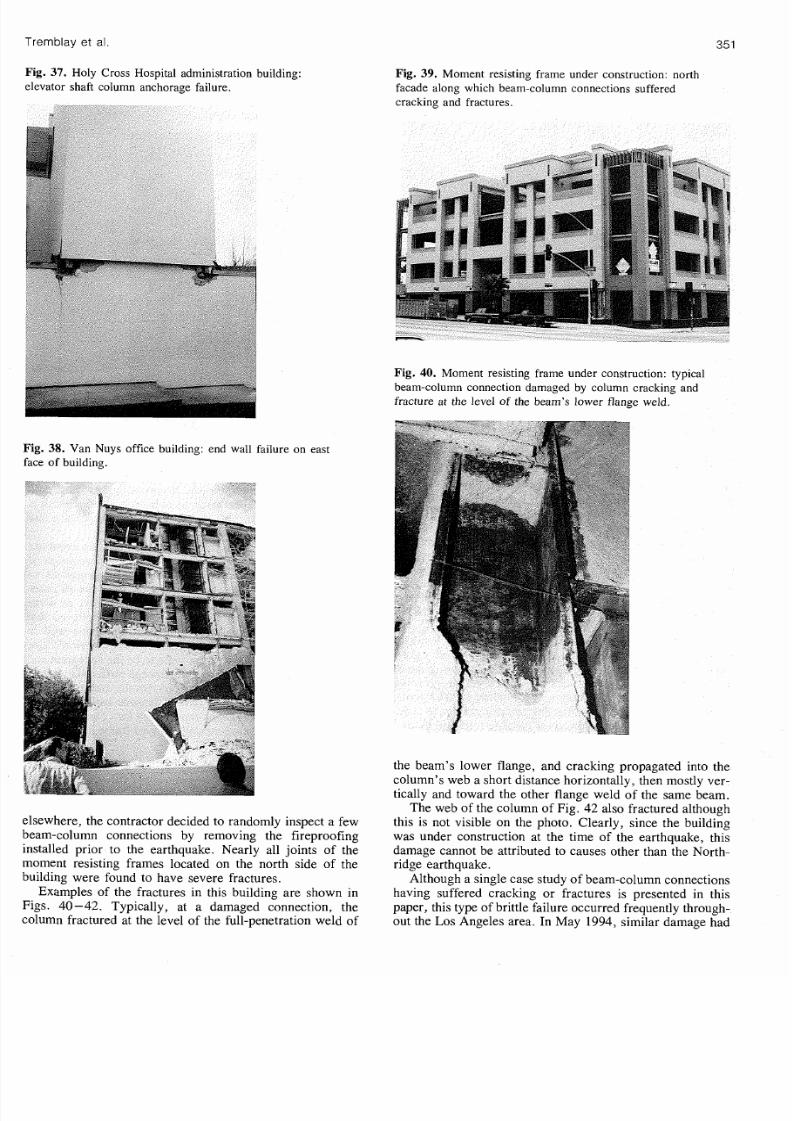
Fig 40
Moment resisting frame under construction: typical
beam-column connection damaged by column cracking and
fracture at the level of the beam s lowe r flange weld.
38 Van Nuys office building: end wall fa ~ilure n east
the beam s lower flange, and cracking propagated into the
column s w eb a sho rt distance horizontally, then mostly ver-
ticallv and toward the other flange weld of the same beam.
Examples of the fractures in this building are shown in
40-4 2. Typically, at a damaged connection, the
h
web of the column of Fig. 42 also fractured although
this is not visible on the photo. Clearly, since the building
was under construction at the time of the earthquake, this
damage cannot be attributed to causes other than the North-
ridge earthquake.
Although a single case study of beam -column connections
having suffered cracking or fractures is presented in this
paper, this type of brittle failure occurred frequently through-
out the Los Angeles area. In May 1994, similar damage had

8/10/2019 Performance of Steel Structures During the 1994 Northridge Earthquake
http://slidepdf.com/reader/full/performance-of-steel-structures-during-the-1994-northridge-earthquake 15/23

8/10/2019 Performance of Steel Structures During the 1994 Northridge Earthquake
http://slidepdf.com/reader/full/performance-of-steel-structures-during-the-1994-northridge-earthquake 16/23
Observations after the Northridge earthquake also indicated
ate additional problems. F or exa mple , out-of-
g., downfall of glass debris, masonry blocks, o r
This problem is somewhat accentuated by the fact that
n be easily achieved for any brace section. Hollow
W shapes with the web in the vertical plane tend to natur-
readily obtained by properly siz-
Damage can, however, be easily prevented by providing
cient free space along each side of the braces or , alterna-
Bending moments that develop at the ends of bracing
the connections and the surrounding structural
ane buckling of bracing m embers is an example o f such
Alternative ways of dissipating energy in braced frames
1993) and could eventually represent promising
apacity design of concentrically braced frames
bers along the lateral load path of concentrically braced
Similar behavior has also been reported for m any other
ited by the Canadian reconnaissance
nt constructed in the early 1950s and located within
6
km
from the epicen ter, exhibited various kinds of tension
failures in its braces (G. Hichborn, 1994, private communi-
cation). Failure modes included complete tensile fracture of
two braces at their connections, serious tearing and deforma-
tion in most angle clips, partial plate pull through of rivets,
and permanent elongation deformations of remaining braces.
Another nearby structure, also several decades old, was
constructed as stacked framing modules. Each module con-
tained four column s with con nection flanges at their ends and
incorporated seismic cross or knee bracing. This structure
experienced column flange bolt failure in single shear. The
four bolts failed completely in all of the first level column
splices. Shearing between the first and second level modules
was accompanied by severe horizontal translation. Luckily,
this movement was stopped by a heavy walled water supply
pipe running up one of the columns. Further motion would
have resulted in catastrophic failure of the fully loaded struc-
ture. In addition, ma ny of this plant's foundation anc hors
failed in combined tension and s hea r, while others deformed
significantly by elongation.
This broad rang e of failure types illustrates very well how
arbitrary and uncontrolled the seismic performance of con-
centrically braced frames can be when a comprehensive
capacity design has not been applied thoroughly. During a
strong ground shaking, the most overstressed element in the
as-built lateral load resisting system reaches invariably its
capacity first. Because braced frames inherently exhibit very
low redundancy, this overstressed element would have to
undergo substantial inelastic deformation prior to sub sequent
redistribution, if any , of forces to other elemen ts. Failure of
the element may then occur early in the earthquake if it does
not possess sufficient toughness to absorb the energy fed into
it by the ground motion.
Such behavior would be typical of ordinary braced frames.
Although higher seismic loads are prescribed for that system ,
they still represent only a fraction of the loads that would be
expected in a structure responding elastically to the design
base earthquake (40 when comparing the elastic and design
1990 NBCC base shears). Thus, some degree of inelastic
response is still anticipated in ordinary braced frames and
premature failure is probable if the weakest elemen t does not
exhibit enough ductility. This could be the case, for instance,
of concrete roof and floor diaphragms or welded connec-
tions. Anchor bolts are also prone to early failure as the
demand o n these elements can easily excee d their capacity to
absorb energy.
Many of the braced frames damaged during the North-
ridge earthquake we re rather old and m ost likely belonged to
the ordinary braced fram e category. D espite the higher seis-
mic design loads prescribed for these braced frames, they
still remain popular today in seismically active regions
because they require less stringent seismic detailing provi-
sions. Braced frames with some degree of ductile detailing
were also found to have behaved in a similar uncontrolled
manner in Northridge; that is, exhibiting inelastic action or
failures away from the braces. This was the case, for exam-
ple, for the Oviatt Library Building, built in 1991 , or the
First Interstate Bank Building retrofitted the same year. In
these structures, most likely the capacity check on the
damaged elements had not been performed or had not
included all the effects that actually occurred during the
earthquake. In Canad a, this undesirable behavior due to lack

8/10/2019 Performance of Steel Structures During the 1994 Northridge Earthquake
http://slidepdf.com/reader/full/performance-of-steel-structures-during-the-1994-northridge-earthquake 17/23
Can. J. Civ. Eng. Vol.
22
199
of capacity check in the original design may occur in any
ductile braced fram e, since, as mentioned earlie r, the design
provisions included in the S16.1 standard only apply to the
steel framing members and not to other elements of the
lateral load resisting system. The secondary bending moments
developed at the ends of the bracing me mb ers upon buckling
is an example of effects that may occur during a n earthquake.
Because of the low redundancy of concentrically braced
frames, any failure along the lateral load path can severely
degrade the stiffness and the strength of the lateral load
resisting system. The structure can then experience large
horizontal deformations and, ultimately, collapse. As men-
tioned, all damaged concentrically braced frames inspected
survived the Northridge earthquake and its aftershocks.
However, the potentially adverse effects that the damage
observed could have had on the stability of the structures,
had the earthquake lasted longer, strongly suggest that any
braced frame should be designed in such a manner that
inelastic response be constrained to the ductile elements,
namely the bracing members. This means that, desirably, a
capacity design philosophy should be implemented fo r
i)
all
braced frame categories and
ii)
the entire lateral load resist-
ing system, including diaphragms, anchorage to the founda-
tions, and the foundations themselves.
Even though anchorage and diaphragm failure have not
been observed in moment resisting frames, the sam e approach
should also be applied to this system for improved seismic
~ e r f o r m a n c e .
Implementing a comprehensive capacity design approach
to column base connections and foundations of concentri-
cally braced frames and moment resisting fra mes still rema ins,
however, a matter of debate. Some recent investigations e.g .,
Filiatrault et al. 1992) have suggested that intentionally
allowing rocking of the foundations or inelastic elongation of
anchor bolts at the base of vertical bracing bents may not
adversely affect the ability of a structure to sustain earth-
quake ground shaking. Such behavior may, on the other
hand, lead to an unacceptable level of horizontal deforma-
tions and should be thoroughly analyzed before construction.
Vertical ground motions in the design of concentrically
braced frames
Significant levels of vertical ground motions have been
recorded during the Northridge earthquake Finn and Ventura
1994). Such vertical accelerations are known to be of sig-
nificance for horizontal cantilevered structures BSSC 1991)
such as the roof cov ering the bleachers of the football field
at the California State University at Northridge. Th e nurner-
ous anchorage failures observed at the base of the exterior
columns of bracin g bents in concentrically braced fram es
suggest that these structures could have been also affected by
vertical accelerations.
Substantial compressive and tensile axial load s develop in
the exterior columns of bracing bents of concentrically
braced frames to resist the overturning moment produced
by horizontal earthquake ground motion. Indeed, it is not
uncomm on to have the combination of the gravity loads plus
these overturning induced forces governing the sizing of
these columns. Obviously, anchorage at the base of bracing
bents is mainly provided for resisting that overturning m oment.
Therefore, it is very muc h likely that these columns and their
anchorage become ove rstressed under the combined action o
the horizontal and vertical ground motions, a situation tha
probably occurred in Northridge.
Such a combined effect is not explicitly addressed in cur
rent Canadian codes. Neither is the effect of vertical a cceler
ations on horizontal cantilevers. T hu s, it is suggested that th
hazard potential of these two effects be assessed for struc
tures located in Canada and, if deemed of significance, tha
appropriate design provisions subsequently be implemented
in codes.
Nonstructural damage
Many of the structures visited experienced larg e interstorey
drifts and suffered extensive nonstructural damage. Mom en
resisting frames, being more flexible than braced frames
appeared to be involved in the more critical situations. In
som e cases, the extent of damage was such that many injurie
and even fatalities could have occurred had the buildings
been occupied during the earthquake. Large portions o
exterior walls and interior partitions collapsed, glass broke
suspended ceilings and mechanical equipment toppled, etc
The objective of the NBCC earthquake-resistant design
provisions is to prevent not only building collapses but als
loss of life. Th erefore , as mentioned ea rlier, hazard potentia
associated with nonstructural damage should be explicitly
addressed at the design stage.
Controlling horizontal drift certainly is a possible avenu
in preventing dam age in a structure. T his can be achieved by
increasing the stiffness of the lateral load resisting system
For short period structures, a more appropriate approach
would be to increase the strength to limit the drift to a targe
value. This can be done by using inelastic displacemen
spectra, as proposed by Priestley 1993).
Nonstmctural damage can also be limited by using bette
construction techniques such as stronger wall attachme nts o
improved suspended ceiling structures. Alternatively, prope
structural and architectural detailing c an be provided, whic
can allow the anticipated deformation to take place withou
failure or collapse due to pounding, tearing, or loss of sup
port. Without doubt, the existence of a good collaboratio
and comm unication between the architect and the engineer i
also part of the solution to such problems.
Regardless of the approach used, engineers must humbl
recognize that a great d eal of uncertainty is associated w it
predicting drift in seismic design. Such incertitude should b
reflected in design an d details by allowing a sufficient margi
of safety.
onnection failures in moment resisting frames
Th e brittle fracture of field welded beam -to-column connec
tions in steel moment resisting frame s is one of the most sig
nificant issue of the Northridge earthquake. Th e following i
a summ ary of the information available as of Novem ber 199
on this consequential structural damage.
The first connection failures were reported only week
after the earthquake, mainly in buildings unde r construction
where finishing and fireproofing materials had not bee
installed yet, or in buildings exhibiting significant permane n
interstorey drifts which indicated that som e structural damag
had likely taken place. In many cases, however, no apparen
sway n or architectural dama ge could suggest that failure ha

8/10/2019 Performance of Steel Structures During the 1994 Northridge Earthquake
http://slidepdf.com/reader/full/performance-of-steel-structures-during-the-1994-northridge-earthquake 18/23
Tremblay et al
occu rred, and the structure was declared safe for occupancy
after the initial inspection. Failures in connections were
found only after structural engineers, recognizing the sig-
nificance of the problem, required random inspection of
more failures and prompting other engineers and owners to
act similarly. In other cases, buildings were reinspectd after
owners had noticed that damage caused by aftershocks was
more important than that produced by the main event.
Failures of beam-column connections were then detected
which had likelv diminished the stiffness of the structures.
Most of thed structures that have suffered fractures a t
beam-column joints had been constructed po st-1980 and had
een designed as special moment resisting frames, which is
the equivalent American designation for- the S 16.1 ductile
moment resisting frame categ ory. It is worth mentioning that
frequent design practice is to incorporate these special
moment resisting frames for only portions of the available
building dimension, usually centrally located on the exterior
perimeters. In such an arrangement, one can take advantage
of the reduced res scribed seismic loads for ductile m omen t
resisting frames while minimizing the costs associated with
the construction of moment resisting fram es. Ho wever, larger
members and connections are required in the bracing bays
when compared to structures with more evenly distributed
moment connected frames.
Occurrence of damage in Northridge does not appear to
have been limited to a given range of building height. A
survey presented by Ross and Mahin (1994) indicates that
75 buildings for which a permit has been issued for repair in
the city of L os Angeles vary from 1 to 22 stories in height.
Ghosh (1994) reports that buildings from 1 to 27 stories have
been dam aged, the majority being less than six stories high.
Sabol (1994) indicates that connection failures in taller struc-
tures generally o ccurred in the uppe r half to two thirds of the
building whereas lower frames were more evenly damaged.
The observed failure rate in a building varied from less than
10 to nearly 100 of the connections. It was also noticed
that failures occurred in both types of construction: buildings
with nearly all frames moment connected and structures
including only a few moment resisting frames. However, it
appears that more buildings of the second type experienced
structural damage (Bertero et al. 1994).
All fractured joints were of the welded flange and bolted
web type, as shown in Fig. 43. Som e had their vertical shear
connectors partially welded to the beam web. Each discov-
ered failure had full-penetration weld fractures in the bottom
flange, very few had these fractures in the top flange. In all
cases, there was little or n o evidence that plastic hinging had
developed in the beams prior to weld fracture. Som e damaged
connections also exhibited vertical cracking through th e
shear connector or shearing of the web bolts. It is believed
that this secondary mode of failure developed as the beam
rotated relative to the face of the column after fracture of the
beam flange weld had occurred.
Figure 44 shows som e of the failure modes that have been
observed at the bottom flange of the beams. R eports indicate
that most cracking initiated in the roo t pass of the weld , near
the steel back-up bar. Type 1 and
2
cracks were very fre-
quent. Failures of type 2 could be readily identified in the
field. Type 1 failures can also be detected through visual
Fig
43 Typical welded flange and bolted web beam-column
connection in moment resisting frames.
ONTINUITY
flm
NOT H
ONDITION
inspection as the backing bar separated from the column fac e
(Miller 1994). Type 3 and 4 failures are similar to types 1
and 2, but crack propagation took place into the column
flange rather than at the interface between the weld and the
column flange material. Typ e 3 cracks can be detected only
by means of ultrasonic inspection, as these crack s do not exit
the column flange surface.
In other connections, cracks deve loped across the column
flange (type 5) and, in some cases, propagated further into
the column web (type 6) (see also Figs. 40-4 2). Miller
(1994) reports that som e column s completely fractured hori-
zontally. A few connections also exhibited a crac k across the
beam flange (type 7) and, ac cording to Bertero et al. (1994),
one case of column lamellar tearing (type 8) has been reported.
A review of the literature on the experimental research
performed in the U.S. and Japan on moment connections in
the past 25 yea rs (Bertero et al. 1994) reveals that the seismic
performance of welded joint spe cimens varied from very good
to very poor. Indeed, many test programs (e .g., Bruneau and
Mahin 1990; Engelhardt and Hussain 1993) had demon-
strated that fracture and brittle failures similar to those
observed after the Northridge earthquake could occur in
heavily welded steel beam-column connections, even when
these were constructed in-shop by competent commercial
structural steel fabricators, using certified welde rs and ultra-
sonic inspection.
For som e reasons, these unfavorable results did not make
completely their way through the engineering community

8/10/2019 Performance of Steel Structures During the 1994 Northridge Earthquake
http://slidepdf.com/reader/full/performance-of-steel-structures-during-the-1994-northridge-earthquake 19/23
Can
J
Civ Eng
Vol. 22 1995
Fig 44. Typical failure modes in beam flange to column connections (adapted from Bertero
et al. 1994; Miller 1994; Ross and Mahin 1994).
TYPE TYPE
2
TYPE TYPE TYPE
7
TYPE
5
TYPE 6 TYPE
8
and, as mentioned ea rlier, the full-penetration welded flange
connection was still recommended in U.S. codes and exten-
sively used in California at the time of the earthquake. Thus ,
the considerable number of brittle failures that occurred in
the Northridge a rea as a result of the earthquake was not sur-
prising. However, the reasons for the failures observed in
laboratory had n ot yet been clearly identified by researc hers.
Thu s, only tentative explanations could be formu lated for the
damage experienced by steel moment resisting frames in the
Northridge earthquake.
Cracking of the beam flange welds has been m ainly attrib-
uted to overstressing of the welds and to weld defects. During
the welding process, significant stresses can be induced in
the welds because moment connections are highly restrained.
Upon loading, welds become overstressed because of the
inadequacy of the bolted web connection to transfer bending
moments; at the column face, increased axial stresses
develop in the beam flanges as the full plastic moment of the
beam must be entirely resisted by the flanges only. The fact
that actual beam material may exhibit lower tensile to yield
strength ratios could also have contributed in overloading the
welds of the beam flanges.
These high stresses make the connections sensitive to
weld imperfections. After the earthquake, weld flaws of
many types have been identified on failed connections: lack
of fusion and penetration in the root region of the welds,
inadequate fusion between multipath welds and adjacent base
metal, use of end d ams instead of proper weld tabs, slag
inclusions left in the welds because of the nature of the access
to the area to be welded, etc. Inadequate preheat and cooling
rates are also seen a s possible contributors to weld failures.
In addition , left-in-place steel backing b ars crea te a notchlike
condition (F ig. 43 that may have led to stress concentration
in the welds and initiation of cracking.
Th e presence of beam flange continuity plates between the
flanges of the columns may also have played a role in the
weld failures. For instance, two 18-storey buildings dis-
played beam-column joint fractures; however, one struc-
tures' extent of weld failure was more than the others. The
main difference in construction between the two high-rises
was the use of continuity plates in columns. The building
with the beam flange continuity plates had less weld failures
than its counterpart, which suggests that the flexibility of the
column flanges could have resulted in local overstressing of
the welds.
Th e predominance of failures at the beam bottom flange,
rather than at the top flange, has been partly attributed to the
additional rotational restraint introduced by the composite
floor slab and the web connector, the latter being usually
located close to the top flange. Bottom flange welds a re also
seen as better candidates for prematu re fracture. Weld exe-
cution at the bottom flange is more difficult because of the
beam web interference, which makes these welds more prone
to imperfections. Another p ossible reason why weld failures
occurred at the bottom flange is the fact that the notchlike
condition at the top flange exists on the side of the flange
opposite to the sid e subjected to the maximum beam flexural
stresses, which is less critical than the situation prevailing at
the bottom flange.
Other contributing factors to the observed weld failures

8/10/2019 Performance of Steel Structures During the 1994 Northridge Earthquake
http://slidepdf.com/reader/full/performance-of-steel-structures-during-the-1994-northridge-earthquake 20/23
he m aterial, high loading rates and strain rate
, large size of the connecting m embe rs, actual state of
Though an alarm ed reaction is not warranted at this time,
ures led to collapse, the causes of such a deficiency m ust
on earthq uakes, as expected to occ ur
f connection is comm on in practice CISC 1991). Also
Steel frames damaged in the Northridge area will obvi-
y represent a potential hazard in future earthq uakes and
and repa ired. T hus, shortly after
ued a draft regulation w hich required all
ofitted to withstand properly next earthquak es. It must b e
In March 1994, a special task comm ittee of the American
Construction AISC) proposed interim recommen-
he repair of damaged connections and the design
new moment resisting frames AISC 1 9 9 4 ~ ) . or repair,
t was suggested that any cracked material or weld be
emoved and replaced by new steel material or welding. Of
code requ irements. In ad dition, based on the
the performanc e of the joint. T hese are
llustrated in Fig. 45 for the connection shown in Fig. 43.
Firstly, it was suggested that the backing bars of the beam
lange welds be removed, the weld root region backgouged
and , subsequen tly, a reinforcing fillet weld be
he column o r, alternatively, to the vertical shear connectors
s shown in Fig. 4 5. T he third correction consisted in adding
flange reinforcement plates, either vertical ribs or cover
lates, to help transferring to the colu mn the axial loads act-
ing in the beam flanges. The decision of using only one or
more of those three schem es was left to the engineer. Exam -
les of these repair procedures a re presented by Sabol 1994)
nd by Tide 1994). For the design of new structures, AISC
recommended to implement these repair provisions when
Fig 45
Proposed reinforced beam-column joints for retrofit
and new constructions: a)vertical ribs; b) cover plates
adapted from Engelhardt and Sabol 1994).
PLATE M P
o .b 3 SIDES
BACKING BAR REMOVED
ROOT REGION BACKGOUGED
REINFORCED WELD M P
COVER PLATE-
TYP
--
YP
\
F BACK GOUGE
making use of the standard welded flange and bolted web
connection specified in the 1992 AISC Seismic Provisions
for Structural Steel Buildings.
Meanwhile, research has been initiated in the United
States, as well as in other co untries, to explain the observed
connection failures and to propo se solutions. In particular, a
test program was started in April 1994 to develop guidelines
for improved moment connections Engelhardt and Sabol
1994). A total of 16 full-scale specimens mad e of heavy
members were tested under cyclic loading, which permitted
to examine the performance of four different connection
details. Testing was completed in October 1994. Based on
the results and additional knowledge gained during that
period of time, AISC published a second set of interim guide -
lines for repair and design of steel moment resisting frames
AISC 19946). These test results and guidelines are briefly
summarized in the following.
The first connection detail was of the standard welded
flange and bolted type Fig. 43), but the beam flange welds
had been improved as shown in Fig. 45a. The second con-
nection was similar except that the beam web was welded
directly to the c olumn, making this connection an all-welded
detail. Upon loading, all specimens of these two connection
details experienced brittle fracture at the beam flange weld
early in the test, with no or little plastic rotation in the beam.
The third type of joint included reinforcement plates as
illustrated in Fig. 45. Cover plates were used in eight sam-
ples whereas two specimens included vertical ribs. More
effort was directed toward the testing of cover-plated speci-
mens a s this detail appears to be less expensive. In these sam -
ples, the section modulus at the face of the column ranged
between 1.6 and 2.0 times that of the unreinforced beam.

8/10/2019 Performance of Steel Structures During the 1994 Northridge Earthquake
http://slidepdf.com/reader/full/performance-of-steel-structures-during-the-1994-northridge-earthquake 21/23
Can. J. Civ. Eng.
Vol.
22
1995
Standard bolted web connection was used in these connec-
tions. In all samples but two, the beam underwent large plas-
tic rotation (between 0.025 and 0.035 rad) and exhibited high
energy dissipation. Both failures initiated in beam flange
weld of cover-plated connections. In one sample, failure took
place at the interface of the weld and the column flange,
whereas crack propagated into the column flange material in
the second failed specimen.
The fourth connection design examined in the test pro-
gram included side straps connecting the outer edges of the
beam flanges to the outer edge of the column continuity plates.
This arrangement (not shown here) had been proposed to
avoid through-thickness failure of the column flange. In the
tests, both samples of this joint exhibited only fair perfor-
mance with failure occurring at plastic rotations less than
0.02 rad (this value is generally considered as the minimum
level for acceptance). This detail was also the most costly to
fabricate.
Although limited in scope, this experiment clearly indi-
cated that improving welding quality was not sufficient by
itself to achieve the desired performance. On the other hand,
shifting the plastic hinging in the beams away from the face
of the column by reducing the stress level in the welds through
reinforcement plates appeared to be promising. However,
brittle failures still occurred in the reinforced connections,
which suggests that other issues such as the through-
thickness properties of the column flange material and the
presence of continuity plates (one of the reinforced joint
which failed early did not have continuity plates) need fur-
ther investigation.
On the basis of these findings, AISC reiterated that the use
of the standard welded beam and bolted web connection
described in the 1992 Seismic Provisions should be sus-
pended unless it can be shown that such connection is ade-
quate or that proper reinforcement is provided. It must be
noted that in September 1994, the ICBO had deleted from the
1994 UBC code the section that allowed the use of this con-
nection without testing and calculation. In view of the
difficulty experienced in achieving high quality welds and
detecting weld defects in the test program, AISC also recom-
mended that all welding be performed in strict compliance
with comprehensive welding procedure specifications to be
developed for each project and suggested that ultrasonic test-
ing of groove welds be conducted from the top and bottom
sides of the welds as well as from the back side of the column
flange.
American Institute of Steel Construction also developed
tentative provisions to assess the adequacy of existing con-
nections and to design reinforced joints (Englekirk 1994).
The approach directly accounts for material overstrength,
lower reliability of through-thickness resistance of steel, and
actual stress -strain relationships of the different materials
involved (weld, base metal, etc.). It also includes ultimate
strain limit states for weld metal and steel material. Unfor-
tunately, the testing program did not investigate all the possi-
ble contributing factors to the observed connection failures in
Northridge and the provisions could not be thoroughly vali-
dated. Moreover, data on the mechanical properties of the
material and on the initial state of stress and strain in connec-
tions are also insufficient. Even the expected demand on the
components of moment resisting frames in future earth-
quakes, including the effects of vertical accelerations, needs
to be established for design purposes.
Thus, not enough information is yet available to structural
engineers for implementing sound repair schemes or design-
ing reinforced connections in moment resisting frames. The
Structural Engineers Association of California (SEAOC), the
Applied Technology Council (ATC), and the California
Universities for Research in Earthquake Engineering (CUREE)
have engaged in a joint effort, namely the SAC Joint Ven-
ture, to solve this problem. Their objectives are to under-
stand what happened to steel moment resisting frames in the
Northridge earthquake, to provide guidance for the identifi-
cation and assessment of damage in buildings, and, finally,
to prepare recommendations for the repair, retrofit, and
design of steel moment resisting frames.
The initial phase of this research effort started in Novem-
ber 1994 and is mainly devoted to the development of interim
guidelines for the repair and inspection of existing structures.
This 2.3 million U.S. program, which is funded by the
Federal Emergency Management Agency and the California
Office of Emergency Services, is expected to be completed
in the Spring of 1995 (A. Ross, 1994, private communica-
tion). Within the next 3 years, it is expected that an additional
10 million U.S. research will be carried out by the SAC
Joint Venture to reach its objectives. Findings of this
research and other research programs that are conducted
elsewhere would need to be examined for possible inclusion
in Canadian codes.
Other avenues which have been proposed to enhance the
seismic performance of steel moment frames should also
draw the attention of researchers and designers in the coming
years. For example, intentionally weakening the beams at a
certain distance of the columns would force plastic hinging
in beams away from the connections as reinforcement plates
do. This can be easily achieved by reducing the width of the
flanges over a certain length to create a dog-bone shape, as
proposed by Chen and Yeh
(1994), or by drilling holes in the
beam flanges. Similar behavior could also be obtained by
adding haunches to moment connections. As opposed to
other joints, such a reinforcement scheme would exhibi
higher redundancy in the connection, since failure of a single
weld would not lead to nearly losing all the bending strength
and stiffness of the connection (Bertero et al. 1994). End-
plate beam-column moment connections, when properly
sized, can also be seen as a viable alternative for ductile
response under seismic loading (Tsai and Popov 1990).
Of course, means of dissipating energy other than beam
hinging can also be exploited. Shear yielding in the column
joint panel zone has been known as an efficient way of releas-
ing the inelastic demand on beams and beam-to-column
connections (Popov et al. 1988). The implementation of
dissipating energy devices and base isolation systems in
moment resisting frames also represents a promising avenue
both for retrofit projects and new structures.
Connections failures in moment resisting frames also
raised serious concerns on the overall reliability of structures
braced only by a few moment resisting bays. These struc
tures can be very sensitive to failure of a single connection
and it is questionable whether such a nonredundant system
should classify under the ductile moment resisting frame
category for which superior redundancy is implied. This

8/10/2019 Performance of Steel Structures During the 1994 Northridge Earthquake
http://slidepdf.com/reader/full/performance-of-steel-structures-during-the-1994-northridge-earthquake 22/23
et
al
issue should be add ressed in future editions of building c odes
in Canada.
Conclusions
Some concentrically steel braced frames and steel moment
resisting frames experienced various structural and nonstruc-
tu rd damage during the Northridge earthquake. None of them
collapsed as they generally maintained their gravity load
carrying capacity as well as som e degree of lateral stability.
The observations made and the information presented in
this paper support for the most part the relevance of the cur-
rent seismic design provisions included in the Canadian
building code and standard for steel structures. However,
Canadian researchers, code writing committees, and struc-
tural engineer designers will need to address a number of
additional issues which can have a significant impact on the
seismic resistant design of steel structures and which are not
or deficiently) addressed by the current edition of the Cana-
dian codes and standards. This includes the need to
xtend a capacity design approach to the whole lateral
load resisting system of the structure, as well as to all
categories of moment resisting frames and, particularly,
concentrically braced frames, because of their lower
inherent redundancy;
ccount for secondary effects that occur upon buckling of
bracing members in concentrically braced frames;
onsider vertical ground accelerations in the design of
horizontal cantilever structures and exterior columns of
bracing bents in concentrically braced frames;
ccount for the lower redundancy exhibited by moment
resisting fram es having only a few mom ent resisting bays;
ecognize in the design process the hazard potential from
nonstructural damage occurring during earthquakes.
The first item is most important as the benefits of capacity
design in ensuring a stable ductile behavior positively im pact
structural performance, particularly in view of the large
uncertainties involved in the definition of the design earth-
quake.
One of the main lessons learned from the Northridge
earthquake is the potential deficiency of welded flange and
bolted web beam -colum n joints in moment resisting fra me s.
The observation of the damage and the research performed
so far indicate that this type of connection is not adequate to
allow cyclic flexural hinging to take place in beam s. Though
some interim guidelines have been proposed for the repa ir,
retrofit, and design of beam-column joints in moment resist-
ing frames, further research is still needed to determine the
causes of this deficiency and to propose sound connection
details and design rules. The findings of this work may even-
tually justify the need for strengthening existing moment
resisting frames in seismically active regions of Canada,
even those designed under recent code provisions.
Finally, the Northridge earthquake has sent a strong sig-
nal that careful inspection of steel frames is mandatory after
a seismic event, even though only minor dam age is apparent
from visual preliminary examination.
cknowledgements
The authors gratefully acknowledge the Natural Sciences
and Engineering Research Council of Canada for providing
research funds for the reconnaissance visits and subsequent
investigations. The on-site cooperation of Susan K. Tubbesing
of the Earthquake Engineering Resarch Institute, John Hall
of Caltech, and Bob Harder, Manager of the Van Nuys
Office of the Los Angeles Buildings and Safety Division, is
greatly appreciated. The assistance of John Sherstobitoff of
Sandwell Inc., Denis Mitchell of the Department of Civil
Engineering of McGill University, and RenC Tinawi of the
Department of Civil Engineering of ~ c o l e olytechnique
during the reconnaissance, together with conveyance of
information and photographs from David Bonneville, Jay
Love, and James 0 . Malley of H.J . Degenkolb Associates of
San Francisco is gratefully acknowledged. Material extracted
from conversations with local Los Angeles engineers Charles
Thiel, Jock Scott, and Geoffrey Hichborn Sr. is similarly
appreciated. Michael Engelhardt of the Department of Civil
Engineering, University of Texas, Austin, and Arthur Ross
of the Structural Engineers Association of California, Cali-
forn ia, are also sincerely thanked for their contribution to the
paper. The information provided by CSIMP, OES, and
USGS was invaluable in interpreting the ground motion
characteristics.
References
AISC. 1992. Seismic provisions for structural steel
buildings. American Institute of Steel Construction,
Inc., Chicago, Ill.
AISC. 1994a . Executive summary nterim observations
and recommendations of AISC Special Task Committee
on the Northridge Earthquake. Proceedings of AISC
Special Task Committee on the Northridge Earthquake
Meeting, American Institute of Steel Construction,
Chicago, Ill.
AISC. 19946. AISC Northridge Tec hnical Bulletin No.
Interim observations and recommendations on steel
moment resisting frames. Northridge Steel Update I,
American Institute of Steel Construction, Chicago Ill.
Astaneh-Asl, A., Goel, S.C ., and Hanson, R.D. 1985.
Cyclic out-of-plane buckling of double angle bracing.
ASCE Journal of Structural Engineering, :
1135- 1153.
Bertero, V.V., Anderson, J.C., and Krawinkler, H. 1994.
Performance of steel building structures during the
Northridge earthquake. Earthquake Engineering Research
Center, College of Engine ering, University of California,
Berkeley, Calif., Report No. UCBIEERC-94/09.
Bonneville, D.R. 1994. Northridge earthquake damage to
a modern steel braced frame office building.
Proceedings of the AISC Special Task Committee on
the Northridge Earthquake Meeting, Chicago, Ill.
Bruneau, M., and Mahin, S.A. 1990. Full-scale tests of
butt-welded splices in heavy-rolled steel sections
subjected to primary tensile stresses. Engineering
Journal, American Institute of Steel Construction, 28:
1-17.
BSSC. 199 National Earthquake Hazards Reduction
Program NEH RP) recommended provisions for the
development of seismic regulations for new buildings.
Part I: provisions. Building Safety Seismic Council,
Washington, D.C.
Chen, S.-J . , and Yeh, C.H. 1994. Enhancement of

8/10/2019 Performance of Steel Structures During the 1994 Northridge Earthquake
http://slidepdf.com/reader/full/performance-of-steel-structures-during-the-1994-northridge-earthquake 23/23
Can.
J.
Civ. Eng.
Vol.
22
1995
ductility of steel beam-to-column connections for
seismic resistance. Proceedings of the Structural
Stability Research Council 1994 Task Group Meetings
and Technical Session Bethlehem Pa. pp. 327 -338.
Cheng R.J.J. Rabinovitch J.S. and Yam M.C.H.
1993. Behavior of gusset plate connections under
compressive monotonic and cyclic loadings.
Proceedings of the 1993 Annual Technical Session of
the Structural Stability Research Council Milwaukee
Wis.
CISC. 1991. Handbook of steel construction. 5th ed.
Canadian Institute of Steel Construction Willowdale
Ont.
CSA. 1989. Limit state design of steel structures.
Canadian Standards Association Rexdale Ont.
Standard CANICSA-S 16.1-M89.
EERI. 1994. Northridge earthquake January 17 1994
Preliminary reconnaissance report. Earthquake
Engineering Research Institute Oakland Calif. Report
NO. 94-0 1.
Engelhardt M.D. and Hussain A.S. 1993. Cyclic-
loading performance of welded flange-bolted web
connections. ASCE Journal of Structural Engineering
119: 3537-3549.
Engelhardt M.D. and Sabol T.A. 1994. Testing of
welded steel moment connections in response to the
Northridge earthquake. Progress report to the AISC
Advisory Subcommittee on Special Moment Resisting
Frames Research Northridge Steel Update I American
Institute of Steel Construction Chicago Ill.
Englekirk R.E. 1994. Design implications derived from
the University of Texas Austin test program.
Northridge Steel Update I American Institute of Steel
Construction Chicago Ill.
Filiatrault A. Anderson D.L. and DeVall R.H. 1992.
Effect of weak foundation on the seismic response of
core wall type buildings. Canadian Journal of Civil
Engineering 19: 530-539.
Finn W.D. and Ventura C.E. 1994. Ground motions.
Preliminary report on the Northridge California
earthquake of January 17 1994. Canadian Association
for Earthquake Engineering Vancouver B.C.
pp. 7-71.
Ghosh S.K. 1994. Code implications of the Northridge
earthquake of January 17 1994. Proceedings of the
Sixth ATC 15-5 U.S. Japan Workshop on the
Improvement of Building Structural Design and
Construction Practices Victoria B.C. pp. 3.1 -3.16.
ICBO. 1982. Uniform building code. International
Conference of Building Officials Whittier Calif.
ICBO. 1994. Uniform building code. International
Conference of Building Officials Whittier Calif.
Khatib I.F. Mahin S.A. and Pister K.S. 1988. Seismic
behavior of concentrically braced steel frames.
Earthquake Engineering Research Center University
of California Berkeley Calif. Report
NO. UCBIEERC-88/01.
Knoll F. 1993. Seismic performance of reinforced
concrete ductile moment-resisting frame buildings
concrete-filled tubular braces. ASCE Journal of
Structural Engineering 14: 1488 1506.
Miller D.K. 1994. Northridge: the role of welding
clarified. The Welding Innovation Quarterly The
James F. Lincoln Arc Welding Foundation
IX
4- 13.
Mitchell D. DeVall R.H. Saatcioglu M. Simpson R.
Tinawi R. and Tremblay R. 1995. Damage to
concrete structures due to the 1994 Northridge earthquake.
Canadian Journal of Civil Engineering 22: 361 -377.
NRCC. 1990. National building code of Canada 1990.
10th ed. Associate Committee on the National Building
Code National Research Council of Canada Ottawa
Ont.
Popov E.P. and Black R.G. 1981. Steel struts under
severe cyclic loadings. ASCE Journal of the Structural
Engineering Division 107: 1857 1881.
Popov E.P. Tsai K.-C. and Engelhardt M.D. 1988.
On seismic steel joints and connections. Proceedings of
the 57th Annual Convention Structural Engineers
Association of California Makahiki Hawaii
pp. 187-208.
Priestley M.J.N. 1993. Myths and fallacies in earthquake
engineering onflicts between design and reality.
Bulletin of the New Zealand National Society for
Earthquake Engineering 26: 329 -348.
Redwood R.G. and Channagiri V.S. 199 1. Earthquake
resistant design of concentrically braced steel frames.
Canadian Journal of Civil Engineering 18: 839 50.
Redwood R.G. Lefki L. and Amar G. 1990.
Earthquake resistant design of steel moment resistant
frames. Canadian Journal of Civil Engineering 17:
659-667.
Roeder G.C. Carpenter J.E. and Taniguchi H.
1989.
Predicted ductility demands for steel moment resisting
frames. Earthquake Spectra
:
409 -427.
Ross A.E. and Mahin S.H. 1994. Steel moment resisting
frames and the Northridge earthquake. Proceedings of
the Sixth ATC 15-5 U.S. Japan Workshop on the
Improvement of Building Structural Design and
Construction Practices Victoria B.C. pp. 10.1 10.10.
Sabol T.A. 1994. Damage to ductile steel frames in the
Northridge earthquake. Proceedings of AISC Special
Task Committee on the Northridge Earthquake
Meeting Chicago Ill.
Tide R.H.R. 1994. Fracture of welded beam-to-column
connections when subjected to seismic loadings.
Proceedings of AISC Special Task Committee on the
Northridge Earthquake Meeting Chicago Ill.
Tremblay R. and Stiemer S.F. 1993. A contribution to
friction bolted connections for concentrically braced
steel frames. Is your structure suitably braced? 1993
Structural Stability Research Council Conference
Milwaukee Wis. pp. 189-200.
Tsai K.-C. and Popov E.P. 1990. Cyclic behavior of
end-plate moment connections. ASCE Journal of
Structural Engineering 116: 2917-2930.
White R.N. and Salmon C.G. 1987. Building structural
design handbook. John Wiley Sons New York N.Y.
Yanvec P.I. Gillengerten J.D. and Hamburger R.O.