PERFORMANCE OF KINETIC ENERGY PROJECTILE - … · PERFORMANCE OF KINETIC ENERGY PROJECTILE -...
23
M. Arad, D. Touati, A. Pila and I. Latovitz M. Arad, D. Touati, A. Pila and I. Latovitz PERFORMANCE OF KINETIC ENERGY PROJECTILE - NUMERICAL AND EXPERIMENTAL STUDY IMI, P.O. Box 1104, IMI, P.O. Box 1104, Ramat Ramat Hasharon 47100, Israel Hasharon 47100, Israel
Transcript of PERFORMANCE OF KINETIC ENERGY PROJECTILE - … · PERFORMANCE OF KINETIC ENERGY PROJECTILE -...

M. Arad, D. Touati, A. Pila and I. LatovitzM. Arad, D. Touati, A. Pila and I. Latovitz
PERFORMANCE OF KINETIC ENERGY PROJECTILE -
NUMERICAL AND EXPERIMENTAL STUDY
IMI, P.O. Box 1104, IMI, P.O. Box 1104, RamatRamat Hasharon 47100, Israel Hasharon 47100, Israel

2
Effect of Yaw and Obliquity on Penetration
n High velocity kinetic energy long rods are one
of the most important munitions of the main
battle tank.

3
Passive armor
n One way to protect a tank against a kinetic
energy long rod is to configure a series of thin
plates as passive armor.
n These plates are generally oblique.
n This target is capable of breaking the rod.

4
Effect of Yaw and Obliquity on Penetration
n The penetration process of a rod while penetrating a
thin and oblique target is characterized by the
following factors:
n erosion at the nose of the rod (large plastic strain)
n rotation and bending of the rod
n long rod breakage
n interaction between the broken parts and the target
n Yaw worsens the above phenomena

5
The goals of the present work
n To build a numerical simulation of the penetrationprocess.
n Validation of the numerical model withexperimental results.
n Using the model to study the influence of the initialyaw on projectile penetrability.
n Using the numerical model to design an improvedprojectile.

6
Obliquity is the angle between the velocity vector
of the rod and the normal to the target.
V
Obliquity
7
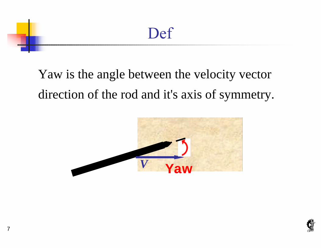
Yaw is the angle between the velocity vector
direction of the rod and it's axis of symmetry.
V YawV Yaw

8
Initial Yaw Sign
Negative initial yaw angle
Zero initial yaw angle
Positive initial yaw angle
VVVV
VV

9

10
n The tungsten-alloy long rod penetrates the thin
steel target
Schematic of the Experimental Set-up
50 mm ≈700 mm
V=1600 m/s 65o
L/D=30

11
X-Ray image of the rod after penetration
1600 /V m s=
simulation
Initial yaw ≈ 0°
Experimental Results

12
simulation
Initial yaw ≈ 1°
X-Ray image of the rod after penetration
1600 /V m s=
Experimental Results

13
simulation X-Ray image of the rod after penetration
Initial yaw ≈ -1° 1600 /V m s=
Experimental Results

14
It is apparent that:
n the rod was bent and its nose was broken
n for a negative initial yaw angle the rod bends up
n for a positive initial yaw the rod bends down
n for a zero initial yaw the bending is minimal
Experimental Results

15

16
A three-dimensional time-dependent finite
element numerical simulation (MSC/DYTRAN)
was performed in order to emulate the
penetration process of the rod during and after
target penetration .
Numerical Simulation

17
n Lagrangian explicit model.n adaptive contacts to model the rod - target interactionn a nonlinear, plastic material description with isotropic
hardening:
n a polynomial equation of state: ε
σhE
E0σ0
hy p
h
E EE E
σ σ ε= +−
( )( )
2 3 2 31 2 3 0 1 2 3 0
01 0 1 0
0, 1
0
a a a b b b b ep
a b b e
µ µ µ µ µ µ ρ µ ρµ
ρµ µ ρ µ
+ + + + + + >= = −+ + ≤
Numerical Simulation

18
A failure criterion model in the form of a user written
subroutine was added to the MSC/DYTRAN code:
n it depends upon the state of the material in the element
(stress, strain, pressure …)
n it is based on two types of material failure:n erosion failuren static maximum plastic strain failure
Numerical Simulation

19
Experiment
Numerical Simulation
1600 /V m s= Initial yaw = 0°

20
Experiment
Numerical Simulation
Initial yaw = 1° 1600 /V m s=

21
Experiment
Numerical Simulation
Initial yaw = -1° 1600 /V m s=

22
The bending process:
n enlarges the hole crater in the target
n decreases the rod velocity
n diverts the direction of the penetrator
In addition, for none zero initial yaw values:
n the side of the rod pointing in the direction of its velocity
is damaged. (This side is in greater contact with the
target because of the velocity direction).
Numerical Simulation

23
n The overall results are a weakening of the rod and
a decrease in its ability to penetrate a series of
plates following the original thin plate target.
n For large yaw angles the bending of the long rod
will cause it to break into several pieces.
Numerical Simulation