Performance of GPS, GLONASS and Galileo
15
Eissfeller et al. 185 Performance of GPS, GLONASS and Galileo BERND EISSFELLER, GERALD AMERES, VICTORIA KROPP, DANIEL SANROMA, München ABSTRACT After a short introduction, an overview about the Global Navigation Satellite Systems (GNSS) GPS, GLONASS and Galileo is given. For each system, a status report is presented and then the three main positioning algorithms: Single Point Positioning, Differential Pseudorange and Carrier Phase Positioning are described. In the Summary, the systems are compared and and outlook is given. 1. INTRODUCTION This paper describes the current status of three Global Navigation Satellite Systems (GNSS): The very well-known and widely used US-American NAVSTAR GPS, the Russian GLONASS system and the planned European satellite navigation system Galileo, which will be fully compatible and interoperable with GPS. After reviewing some background information, history and current status, we will have a look at the performance of these satellite based Navigation Systems. We will, however, treat the systems separately and without aiding from external sources like Satellite Based Augmentation Systems (SBAS) that transmit wide area correction information on measurements (WAAS, EGNOS, MSAS), aiding with Inertial Measurement Units (IMUs) or telecommunication technologies like GSM or UMTS. Other future GNSS in early development state are omitted, but will be mentioned briefly in this introduction: China has set up an SBAS-like system called "Beidou" and seems to be prepared to develop a standalone GNSS called "Compass". One satellite is already in orbit, but information about signals and services used are not published. China, together with Nigeria has set-up an SBAS satellite called "NigComsat-1" to provide correction information for the African continent. A similar system using the geostationary satellite "GAGAN" is planned by India. Also Japan plans to set up a system of three satellites to secure good visibility of GNSS satellites in the western Pacific region (Quasi-Zenith Satellite System). GNSS positioning performance varies from a level of 30 m to 50 cm and finally to 1 mm. All these levels of accuracy have been demonstrated. However, it is not always clear which effort was made to gain the described accuracy level. In general, there are three different types of observation ans processing modes in GNSS: Single point positioning, differential (code) measurements and carrier phase observations. In this paper, the different observations are discussed with respect to the satellite system used. We will show that GPS and Galileo use similar signals and signal structures and so receiver development can be carried out similarly for both systems. Because of the frequency multiplex (FDMA) the situation with GLONASS is different. In a GLONASS receiver a front-end with higher complexity has to be implemented. Photogrammetric Week '07 Dieter Fritsch (Ed.) Wichmann Verlag, Heidelberg, 2007
Transcript of Performance of GPS, GLONASS and Galileo

Eissfeller et al. 185
Performance of GPS, GLONASS and Galileo
BERND EISSFELLER, GERALD AMERES, VICTORIA KROPP, DANIEL SANROMA, München
ABSTRACT
After a short introduction, an overview about the Global Navigation Satellite Systems (GNSS) GPS, GLONASS and Galileo is given. For each system, a status report is presented and then the three main positioning algorithms: Single Point Positioning, Differential Pseudorange and Carrier Phase Positioning are described. In the Summary, the systems are compared and and outlook is given.
1. INTRODUCTION
This paper describes the current status of three Global Navigation Satellite Systems (GNSS): The very well-known and widely used US-American NAVSTAR GPS, the Russian GLONASS system and the planned European satellite navigation system Galileo, which will be fully compatible and interoperable with GPS. After reviewing some background information, history and current status, we will have a look at the performance of these satellite based Navigation Systems. We will, however, treat the systems separately and without aiding from external sources like Satellite Based Augmentation Systems (SBAS) that transmit wide area correction information on measurements (WAAS, EGNOS, MSAS), aiding with Inertial Measurement Units (IMUs) or telecommunication technologies like GSM or UMTS. Other future GNSS in early development state are omitted, but will be mentioned briefly in this introduction: China has set up an SBAS-like system called "Beidou" and seems to be prepared to develop a standalone GNSS called "Compass". One satellite is already in orbit, but information about signals and services used are not published. China, together with Nigeria has set-up an SBAS satellite called "NigComsat-1" to provide correction information for the African continent. A similar system using the geostationary satellite "GAGAN" is planned by India. Also Japan plans to set up a system of three satellites to secure good visibility of GNSS satellites in the western Pacific region (Quasi-Zenith Satellite System). GNSS positioning performance varies from a level of 30 m to 50 cm and finally to 1 mm. All these levels of accuracy have been demonstrated. However, it is not always clear which effort was made to gain the described accuracy level. In general, there are three different types of observation ans processing modes in GNSS: Single point positioning, differential (code) measurements and carrier phase observations. In this paper, the different observations are discussed with respect to the satellite system used. We will show that GPS and Galileo use similar signals and signal structures and so receiver development can be carried out similarly for both systems. Because of the frequency multiplex (FDMA) the situation with GLONASS is different. In a GLONASS receiver a front-end with higher complexity has to be implemented.
Photogrammetric Week '07 Dieter Fritsch (Ed.) Wichmann Verlag, Heidelberg, 2007

186 Eissfeller et al.
2. GPS
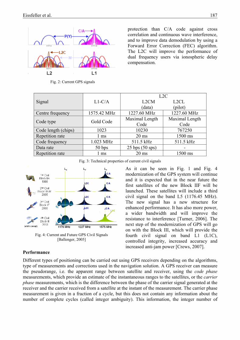
Overview The Global Positioning System (GPS) is a satellite radio navigation system developed by the Department of Defense (DoD) of the USA. The system makes use of a medium earth orbit satellite constellation transmitting microwave signals allowing a GPS receiver to determine its position, velocity and time. The roots of the GPS system are closely connected to the launch of the Sputnik satellite by the Soviet Union in 1957, since the satellite orbit could be determined by observing the Doppler Effect. Using this knowledge the USA developed a satellite system, called TRANSIT. With TRANSIT a position on the ground could be determined by measuring the Doppler shifts of the signals. But this system had no precise timing devices aboard the satellites and calculating a receiver position took about 15 minutes. In 1973, the Department of Defense (DoD) decided to develop a satellite navigation system based on previous systems (like TRANSIT); the concept of the GPS system was born. In 1977 the first receiver tests were performed using pseudolites (or pseudo satellites), i.e. transmitters installed on the earth’s surface. The first operational GPS satellite was launched in 1978. Till 1985, a total of 11 Block I satellites were launched. In the year 1989 a new type of satellite was activated, the first Block II satellite was launched. In 1993 the system reached full 24-satellite constellation. In this year it was also decided to allow the world wide civilian use free of charge. In 1995 Full Operation Capability (FOC) was achieved. Five years later the deactivation of the selective availability was announced, leading to an improvement of the accuracy for civilian users from about 100 m to 20 m. In 2005 the modernization of the GPS system began by launching the first satellite of type IIR-M, which supports a new military M-signal and the second civil signal L2C. As of 12 February 2007 the space segment was built-up by 30 operational satellites: 15 satellites of Block IIA, 12 satellites of Block IIR and 3 satellites of Block IIR-M [Crews, 2007]. The satellites are distributed in 6 orbital planes with an inclination relative to the equatorial plane of 55°. The orbit is nearly circular with a radius of 26650 km and the period is of about 12 hours. The satellites of Block IIA and IIR send the standard GPS signals, i.e. the Coarse/Acquisition (C/A) code on the
L1 band (1575.42 MHz) and the P(Y) code (only for DoD-authorized users) on the L1 and L2 (1227.60 MHz) bands. GPS uses the Code Division Multiple Access (CDMA) technique to send different signals on the same radio frequency and the modulation method used for these basic GPS signals is the Binary Shift Phase Keying (BPSK). The C/A code is a Gold code of 1 millisecond length at a chipping rate of 1.023 Mbps. The precision code, P code, is a one week long sequence code designed for military use.
As said above, the modernization of the GPS system began in 2005 with the block IIR-M. The IIR-M satellites send new military signals on L1 and L2 (L1M & L2M) and a new civil signal on L2 (L2C). The new civil signal is constituted of two ranging codes multiplexed in time: the L2 Civil Moderate (L2 CM) code and the L2 Civil Long (L2 CL) code. The L2C signal is designed to have better correlation properties than the L1-C/A signal due to longer codes. It will provide better
Fig. 1: GPS evolution [Crews, 2007]
Eissfeller et al. 187
protection than C/A code against cross correlation and continuous wave interference, and to improve data demodulation by using a Forward Error Correction (FEC) algorithm. The L2C will improve the performance of dual frequency users via ionospheric delay compensation.
Signal L1-C/A L2C
L2CM L2CL (data) (pilot)
Centre frequency 1575.42 MHz 1227.60 MHz 1227.60 MHz
Code type Gold Code Maximal Length Code
Maximal Length Code
Code length (chips) 1023 10230 767250 Repetition rate 1 ms 20 ms 1500 ms Code frequency 1.023 MHz 511.5 kHz 511.5 kHz Data rate 50 bps 25 bps (50 sps) - Repetition rate 1 ms 20 ms 1500 ms
As it can be seen in Fig. 1 and Fig. 4 modernization of the GPS system will continue and it is expected that in the near future the first satellites of the new Block IIF will be launched. These satellites will include a third civil signal on the band L5 (1176.45 MHz). The new signal has a new structure for enhanced performance. It has also more power, a wider bandwidth and will improve the resistance to interference [Turner, 2006]. The next step of the modernization of GPS will go on with the Block III, which will provide the fourth civil signal on band L1 (L1C), controlled integrity, increased accuracy and increased anti-jam power [Crews, 2007].
Performance Different types of positioning can be carried out using GPS receivers depending on the algorithms, type of measurements and corrections used in the navigation solution. A GPS receiver can measure the pseudorange, i.e. the apparent range between satellite and receiver, using the code phase measurements, which provide an estimate of the instantaneous ranges to the satellites, or the carrier phase measurements, which is the difference between the phase of the carrier signal generated at the receiver and the carrier received from a satellite at the instant of the measurement. The carrier phase measurement is given in a fraction of a cycle, but this does not contain any information about the number of complete cycles (called integer ambiguity). This information, the integer number of
Fig. 2: Current GPS signals
Fig. 3: Technical properties of current civil signals
Fig. 4: Current and Future GPS Civil Signals [Ballenger, 2005]

188 Eissfeller et al.
wavelengths, e.g. 19 cm when using L1, is needed to compute the signal travel time between the receiver and the satellite. The carrier phase measurements are much more precise but to make use of these measurements the integer ambiguity has to be solved and some errors (like multipath or atmospheric delays) have to be mitigated. Absolute positioning relies upon a single receiver. As a result, the absolute positioning is corrupted by unmitigated errors inherent in satellite positioning, such as satellite orbit errors, clock errors of satellite and receiver, atmospheric (ionospheric and tropospheric) errors, multipath and receiver noise. As shown in Fig. 8 the horizontal error using pseudoranges in a L1 single frequency receiver is on the order of 5 to 20 meters. In order to improve the accuracy relative or differential positioning can be used. Differential position is using raw data or corrections from a reference receiver located at a known reference point. Assuming that errors like atmosphere, orbit errors and satellite clock have the same effect on observation sites in a region, these errors can be eliminated by computing differences between measurements. Using a reference station at a point with known coordinates, the errors can be computed and corrections can be used to improve observations at the so-called "rover points". If only code measurements are processed a differential pseudorange solution using pseudorange corrections will be obtained (pseudorange DGPS). This leads to a decrease of the horizontal error to a level of 1-5 meters. Using an antenna located at the top of the roof on building 41/100 in the campus of the University FAF Munich and the software receiver developed at the Institute of Geodesy and Navigation, measurements on the L1 signal were carried out and the pseudorange DGPS solution was calculated. As it can be seen in Fig. 5a the maximal horizontal absolute error using this method was about 4 meters. In Fig. 5b the north, east and height errors are shown, it can be observed that the north and east absolute errors are within ±2 meters, while the maximum absolute error on height (which is the most critical) is about 6 meters. As can be also shown in Fig. 8, the position accuracy can be slightly improved by using carrier-smoothed pseudorange corrections. In this case the pseudorange and carrier phase measurements are combined and the result is a smoothing of the measurement error. The precision of the position can be further improved by using the carrier phase measurements. But as stated before the integer ambiguity has to be solved. A first approximation is to use a float solution, i.e. to calculate a solution using real numbers (and not integer numbers) for the ambiguity. As it can be seen in Fig. 8, this leads to a horizontal error of less than 50 cm. Differential carrier phase processing is the most precise positioning method once the integer ambiguities are resolved. In this case, a navigation solution with a horizontal error of a few centimetres can be achieved. If only static measurements are used (which is standard in surveying) the error decreases to some millimetres.
Fig. 5a: Pseudorange DGPS horizontal absolute error (vertical axis is the: north component and
the horizontal axis is the east component)
Fig. 5b: Pseudorange DGPS absolute error (north, east and height components)

Eissfeller et al. 189
In Fig. 6 the same measurement as in the case of differential pseudorange GPS were used to calculate a differential carrier phase solution. As it can be seen in Fig. 6a and 6b the absolute errors decrease to some millimeters (note that the measurement was taken in an environment with large multipath effects and in a short period of time, for surveying purposes a longer period of time should be used to get a better performance). The horizontal RMS (68%) of this measurement is about 1.5 centimetres. In differential positioning one important parameter that determines the quality of the results is the distance between the receiver and the reference receiver (called base line): The shorter the base line is, the better the achieved accuracy. This can be seen in Fig. 7. In this table are listed the results of some measurements of a flight test taken in Braunschweig using differential carrier phase together with an INS [Hein, 2005]. The results show how many measurements (in %) are within an accuracy of 2, 4 or 8 cm depending on the distance between the plane and the reference receiver. It can be seen for example that about 85% of the measurements achieve accuracy better than 2 cm for a base line of 10 km, and about 45% for a base line of 30 km. If the base line length increases, the number of measurements within the specified accuracy class decreases.
Baseline/ Accuracy
0.02 m 0.04 m 0.08 m
10 km 84.5 98.0 100 30 km 45.2 78.7 99.9 50 km 32.8 56.9 90.9 70 km 18.4 26.8 54.8
As shown in Fig. 8, the error of GPS measurements can vary from some meters to some millimetres depending on the quality of the receiver, the measurements used (code phase and/or carrier phase), the algorithms implemented, the noise of the measurements, the type of measurement (static or dynamic). In case of differential positioning the precision of the solution depends also on the distance between the receiver and the reference receiver.
Fig. 6a: Differential carrier phase horizontal absolute error (vertical axis is the: north component and the
horizontal axis is the east component)
Fig. 6b: Differential carrier phase absolute error (north, east and height components)
Fig. 7: Distribution % of standard deviation as function of base line length

190 Eissfeller et al.
3. GLONASS
GLONASS (GLObal NAvigation Satellite System) is a radio-based satellite navigation system initially developed for the use by the Soviet military. It was the Soviet's second generation satellite navigation system, improving their Tsikada system which required one to two hours of signal processing to calculate a location with high accuracy. The time of observing more than four satellites is limited because GLONASS does not form a complete GNSS currently. But according to state policy, GLONASS is proposed to be full operational by the year 2010, and at the same point to be compatible and interoperable with GPS and future Galileo. The GLONASS development goal is to create more opportunities for the GNSS application developers, allowing them to provide value-added services to end-customers. Development on the GLONASS began in 1976, with a goal of a global coverage by 1991. Beginning in 1982, numerous satellite launches completed the constellation in 1995, 26 satellites were obtained. After completion, the system rapidly fell into decay with the collapse of the Russian economy. Older satellites were taken out of service after their design life time had been exceeded. They were not replaced, so just 8 satellites remained in GLONASS orbits by 2001. To change this situation Russia decided to restore the system by 2011. A Federal program named "Global Navigation System" was undertaken by the Russian government on August 20, 2001 and the Indian government joined the program as a partner, to ensure funding. Both countries emphasized again the civil and in particular the geodetic use of GLONASS.
On May 18, 2007, Russian president Vladimir Putin signed a decree [WWWGLON], providing open access to the civilian navigation signals of the GLONASS system to Russian and foreign consumers free of charge and without limitations. Development and maintenance of GLONASS system is conducted by Federal Space Agency (ROSCOSMOS, MOD). The second, and current, generation of satellites, known as Uragan-M (also called GLONASS-M), were developed beginning in 1990 and first launched in 2001. These satellites possess a substantially increased lifetime of seven years and weigh slightly more at 1,480 kg. Laser corner-cube reflectors are installed as aid for precise orbit determination and geodetic research. GLONASS satellites are equipped with Caesium clocks onboard to provide time and frequency standards. These Caesium clocks have a daily frequency stability of 5·10-13. GLONASS-M (Fig. 9) has
Fig. 8: GPS performance [Hein, 2007]
Fig. 9: GLONASS-M satellite
Eissfeller et al. 191
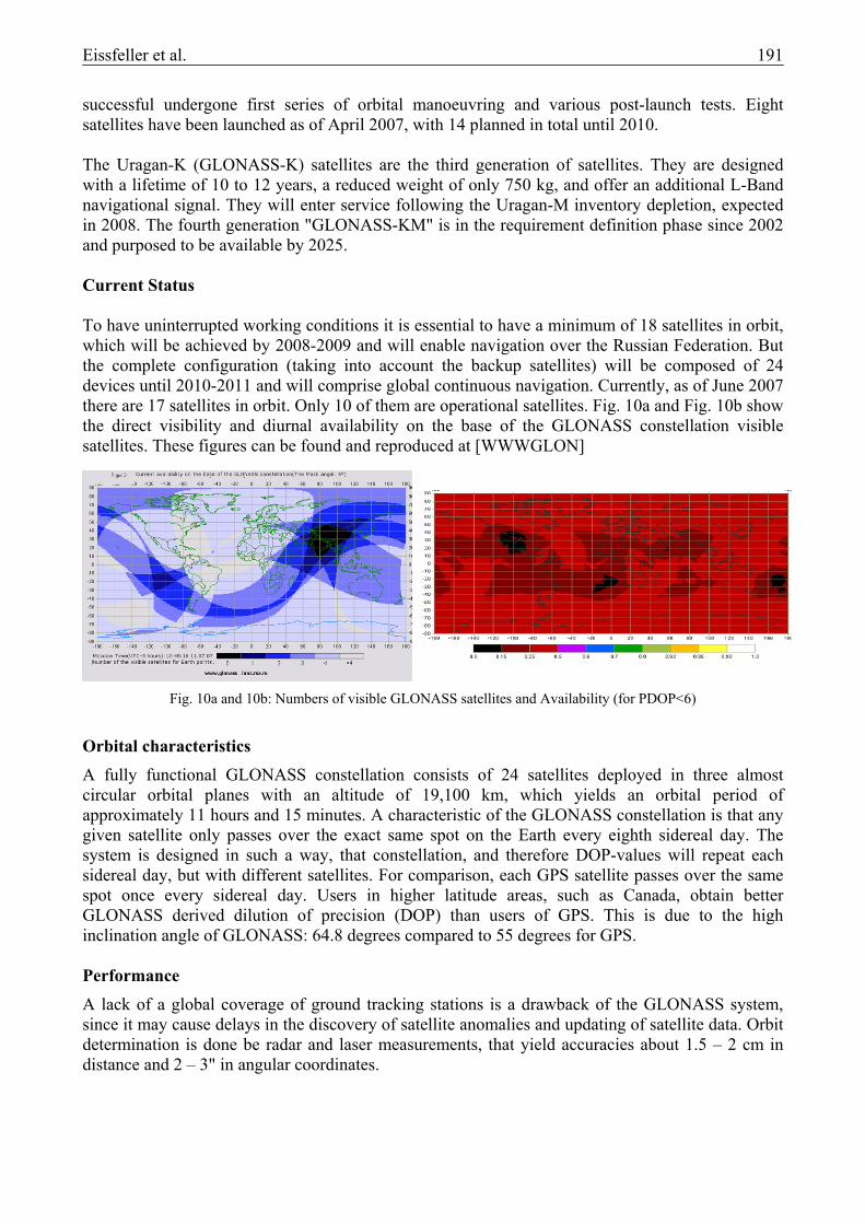
successful undergone first series of orbital manoeuvring and various post-launch tests. Eight satellites have been launched as of April 2007, with 14 planned in total until 2010. The Uragan-K (GLONASS-K) satellites are the third generation of satellites. They are designed with a lifetime of 10 to 12 years, a reduced weight of only 750 kg, and offer an additional L-Band navigational signal. They will enter service following the Uragan-M inventory depletion, expected in 2008. The fourth generation "GLONASS-KM" is in the requirement definition phase since 2002 and purposed to be available by 2025. Current Status To have uninterrupted working conditions it is essential to have a minimum of 18 satellites in orbit, which will be achieved by 2008-2009 and will enable navigation over the Russian Federation. But the complete configuration (taking into account the backup satellites) will be composed of 24 devices until 2010-2011 and will comprise global continuous navigation. Currently, as of June 2007 there are 17 satellites in orbit. Only 10 of them are operational satellites. Fig. 10a and Fig. 10b show the direct visibility and diurnal availability on the base of the GLONASS constellation visible satellites. These figures can be found and reproduced at [WWWGLON]
Orbital characteristics
A fully functional GLONASS constellation consists of 24 satellites deployed in three almost circular orbital planes with an altitude of 19,100 km, which yields an orbital period of approximately 11 hours and 15 minutes. A characteristic of the GLONASS constellation is that any given satellite only passes over the exact same spot on the Earth every eighth sidereal day. The system is designed in such a way, that constellation, and therefore DOP-values will repeat each sidereal day, but with different satellites. For comparison, each GPS satellite passes over the same spot once every sidereal day. Users in higher latitude areas, such as Canada, obtain better GLONASS derived dilution of precision (DOP) than users of GPS. This is due to the high inclination angle of GLONASS: 64.8 degrees compared to 55 degrees for GPS. Performance
A lack of a global coverage of ground tracking stations is a drawback of the GLONASS system, since it may cause delays in the discovery of satellite anomalies and updating of satellite data. Orbit determination is done be radar and laser measurements, that yield accuracies about 1.5 – 2 cm in distance and 2 – 3" in angular coordinates.
Fig. 10a and 10b: Numbers of visible GLONASS satellites and Availability (for PDOP<6)

192 Eissfeller et al.
GLONASS satellites transmit two types of signal: a standard precision (SP) signal and an encrypted high precision (HP) signal. All satellites transmit the same SP signal, however each satellite transmits on a different frequency using a 25-channel frequency division multiple access (FDMA) technique spanning. GLONASS has already had to modify its frequency band – more than once – because of interference to radio astronomy. A third carrier frequency will be used by GLONASS-K in 2008 for higher reliability and accuracy. Like GPS, GLONASS satellites transmit navigational data at 50 bits per second. For GLONASS the wavelengths of the L1 carrier are different for each satellite due to the different frequencies used. The knowledge of the wavelength differences within the L1 carrier of each satellite is crucial for ambiguity resolution. The wavelength difference between the two extremes is 0.15 cm, which is less than 0.01 L1 cycle. The accuracy of GLONASS navigation using the SP signal is specified to be 50-70 m (99.7%) in the horizontal plane and 70 m (99.7%) in height. Accuracy of estimated velocity vectors is 15 cm/s (99.7%). Timing accuracy is 1 µs (99.7%) [ICDGLON].
An example of positioning results using GPS and GLONASS absolute positioning with pseudoranges is shown in Fig. 11a. Positions were computed from data logged by a 3S Navigation R-100/R-101 receiver, which was set up at a known location at the Institute of Geodesy and Navigation. Pseudorange and carrier phase measurements were logged every second for approximately one hour. The plot shows the deviation from the known location of the antenna in the horizontal plane. GPS positions were computed from carrier smoothed L1 C/A–code measurements. Wherever possible, the ionospheric free linear combination was formed. The observables used are not really identical for GPS and GLONASS, but with HP-code and dual-frequency measurements available on GLONASS and GPS the best possible results for each system are determined. GLONASS satellite positions were converted from PZ-90 to WGS84 using the transformation according to [Rossbach, 1996]. The large deviations from the true position due to GPS SA, still present at the time of the measurements in 1996, can be clearly seen. Standard deviations of the computed positions are 25.4 m in North/South direction and 10.0 m in East/West direction. The noise on the GLONASS measurements is smaller due to the lack of SA. The height components of the processing results are displayed in Fig. 11b as a time series. As with the horizontal components, the combined GPS/GLONASS solution also is affected by GPS SA, but to a lesser extent than the GPS only results. Here the standard deviation is 15.5 m.
Fig. 11a: GPS, GLONASS and combined GPS/GLONASS absolute positioning, Fig. 11b: height component (GPS Selective Availability switched on)

Eissfeller et al. 193
Where better accuracy is required, positioning will usually be done in differential mode. In this case, differences in the coordinate frame of the satellite positions can be regarded as orbital errors, which cancel out in differential processing, at least over short baselines. An example of positioning results using GPS and GLONASS single difference positioning with pseudoranges is shown in Fig 12a. Pseudorange and carrier phase measurements were logged every second for approximately one hour each, of which some forty minutes were common to both receivers. The data of the user station are the same as the data already used for the absolute positioning example. The plot shows the deviation from the known location of the antenna of the user station in the horizontal plane. Due to the measurements at reference and user station not being exactly synchronized, the effects of GPS SA do not entirely cancel. Since there is no SA on GLONASS, its effects cannot remain in the differenced positioning solution due to imperfect synchronization of measurements. The height component, displayed in Fig. 12b, show similar behaviour. Forming a single difference, subtracting the measurement at the reference station from that at the user, the satellite clock error will cancel out. For high precision applications, the FDMA technique results in several difficulties in using the standard double difference technique for integer ambiguity resolution. Firstly, the integer nature of the ambiguity term after inter-satellite differencing cannot be preserved. Secondly, each of the signals experiences a different ionospheric delay. Moreover, these delays can be receiver dependent. Finally, a much wider bandwidth must be used in the front-end design to receive the whole range of GLONASS frequencies. This potentially leads to noisier observations and may have a negative impact on ambiguity resolution. To get around this problem, there are generally two solutions available. One may use a single differenced technique with certain constraints and/or aiding to resolve the GLONASS carrier phase ambiguity. Alternatively, one may modify the standard double differenced technique to accommodate the different GLONASS satellite frequencies. Development and production of the GLONASS user equipment for civil and governmental use is conducted by private companies. Some manufacturers – Javad Navigation Systems, Leica, NovAtel, Topcon and Trimble – currently offer combined GPS/GLONASS receivers, used for the surveying market. The differences between FDMA and CDMA signals make offering combined GPS/GLONASS receivers a complex and costly venture, one is unlikely to expand beyond the current high-precision sectors where users will pay for a high-cost receiver if it adds value. Russia will probably add CDMA signals on the third frequency of GLONASS-K satellites and at L1 on GLONASS-M satellites to simplify receiver signal processing and be more interoperable with GPS and the future Galileo. At the September 2006 meeting of the Institute of Navigation, Sergey Revnivykh, deputy director of Mission Control Center of Central Research Institute of Machine
Fig. 12a: GPS, GLONASS and combined GPS/GLONASS single differential positioning, Fig. 12b: height component

194 Eissfeller et al.
Building of the Russian Federal Space Agency (RFSA) spoke of CDMA as an "option" for GLONASS and added that the GLONASS switch to CDMA would make manufacturing combined receivers more easy. Still Russian officials are open for discussions about frequencies and modulation techniques.
4. GALILEO
Galileo has recently been discussed in the pres not because of its benefit due to its improved technical capabilities compared to the American GPS but mainly because of the delay of satellite launches, problems in funding and questions of competence within the European Union. Based on the Communication [EC, 1999] of the European Commission on February 9, 1999, the development of Galileo has been decided. The European Union wants to become independent of GPS which is under control of the Department of Defense of the United States. Additionally the EU wants to profit from the growing market "Satellite based Positioning and Navigation" which today is dominated by US products and infrastructure. The final decision for funding and developing Galileo, however, was not taken until 26.03.2002 by the European Council of the Ministers of Transport. The reason for this delay was a long discussion about the funding concept and therefore the decision who should lead the Galileo project. The result was a 20,9% funding of Germany, 17,0% of France, 16,0% of Great Britain and 15,2% of Italy, with one Control Centre and the headquarters of Galileo Industries in Germany and one Control Centre in Italy. A major topic in the built-up of Galileo, which still was not clarified up to July 2007 is the so-called "Public-Private-Partnership" (PPP): A private company or a consortium of companies establish the Ground Segment, take responsibility for the launch of the 30 Galileo satellites and will then operate the final system. The question of refunding and the formation of the private consortia have slowed down the process of development. As of May 2007 it became clear that the PPP – process failed. It seems that the deployment phase is fully paid by the public, while it is open how the public side will fund the operational and maintenance phase. Frequencies and Signals Fig. 13 and Table 1 show the Carrier frequencies and Signal definitions of Galileo. It can be seen, that Galileo uses three frequency bands: In the lower L-Band E5a (overlapping with the future GPS L5) and E5b with a bandwidth of 24 MHz each. In the middle of the L-Band the E6 with 40 MHz bandwidth and E1, in the upper L-Band with 32.7 MHz are planned. The usability of E6 is questionable as civil and military radar stations radiate in the same frequency range. In contrast, combining E5a and E5b will result in a very robust signal in lower L-Band. The use of E1 was intensively discussed with US officials [Hein, 2006] because interference is expected with GPS L1 and the future GPS military M-Code. As Galileo is supposed [Weber, 2001] to be independent but interoperable with GPS and GLONASS, new modulation techniques were applied to keep interference as small as possible [Wallner, 2006].
Fig. 13: Galileo Signal Definition
Eissfeller et al. 195
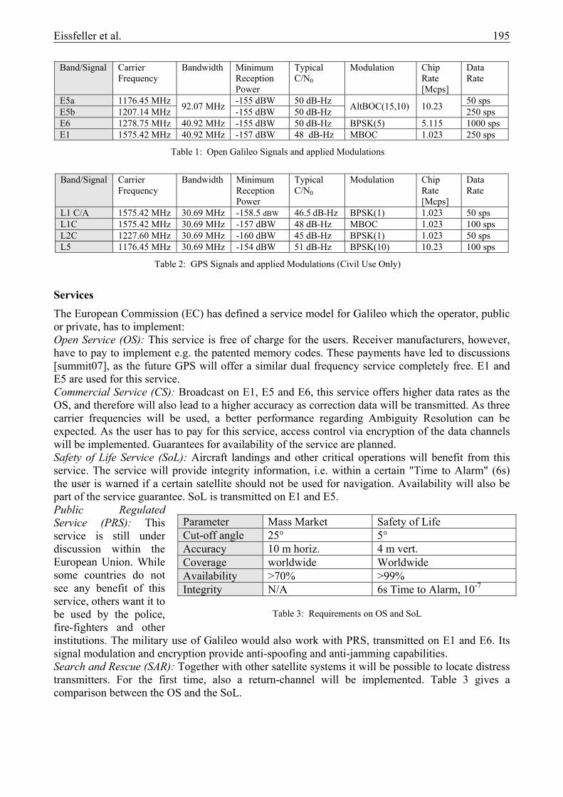
Services The European Commission (EC) has defined a service model for Galileo which the operator, public or private, has to implement: Open Service (OS): This service is free of charge for the users. Receiver manufacturers, however, have to pay to implement e.g. the patented memory codes. These payments have led to discussions [summit07], as the future GPS will offer a similar dual frequency service completely free. E1 and E5 are used for this service. Commercial Service (CS): Broadcast on E1, E5 and E6, this service offers higher data rates as the OS, and therefore will also lead to a higher accuracy as correction data will be transmitted. As three carrier frequencies will be used, a better performance regarding Ambiguity Resolution can be expected. As the user has to pay for this service, access control via encryption of the data channels will be implemented. Guarantees for availability of the service are planned. Safety of Life Service (SoL): Aircraft landings and other critical operations will benefit from this service. The service will provide integrity information, i.e. within a certain "Time to Alarm" (6s) the user is warned if a certain satellite should not be used for navigation. Availability will also be part of the service guarantee. SoL is transmitted on E1 and E5. Public Regulated Service (PRS): This service is still under discussion within the European Union. While some countries do not see any benefit of this service, others want it to be used by the police, fire-fighters and other institutions. The military use of Galileo would also work with PRS, transmitted on E1 and E6. Its signal modulation and encryption provide anti-spoofing and anti-jamming capabilities. Search and Rescue (SAR): Together with other satellite systems it will be possible to locate distress transmitters. For the first time, also a return-channel will be implemented. Table 3 gives a comparison between the OS and the SoL.
Band/Signal Carrier Frequency
Bandwidth Minimum Reception Power
Typical C/N0
Modulation Chip Rate [Mcps]
Data Rate
E5a 1176.45 MHz 92.07 MHz -155 dBW 50 dB-Hz AltBOC(15,10) 10.23 50 sps E5b 1207.14 MHz -155 dBW 50 dB-Hz 250 sps E6 1278.75 MHz 40.92 MHz -155 dBW 50 dB-Hz BPSK(5) 5.115 1000 sps E1 1575.42 MHz 40.92 MHz -157 dBW 48 dB-Hz MBOC 1.023 250 sps
Table 1: Open Galileo Signals and applied Modulations
Band/Signal Carrier
Frequency Bandwidth Minimum
Reception Power
Typical C/N0
Modulation Chip Rate [Mcps]
Data Rate
L1 C/A 1575.42 MHz 30.69 MHz -158.5 dBW 46.5 dB-Hz BPSK(1) 1.023 50 sps L1C 1575.42 MHz 30.69 MHz -157 dBW 48 dB-Hz MBOC 1.023 100 sps L2C 1227.60 MHz 30.69 MHz -160 dBW 45 dB-Hz BPSK(1) 1.023 50 sps L5 1176.45 MHz 30.69 MHz -154 dBW 51 dB-Hz BPSK(10) 10.23 100 sps
Table 2: GPS Signals and applied Modulations (Civil Use Only)
Parameter Mass Market Safety of Life Cut-off angle 25° 5° Accuracy 10 m horiz. 4 m vert. Coverage worldwide Worldwide Availability >70% >99% Integrity N/A 6s Time to Alarm, 10-7
Table 3: Requirements on OS and SoL

196 Eissfeller et al.
Space segment 27 Satellites and 3 spares will orbit the earth in a so-called Walker-constellation evenly distributed on three planes with a radius of 29600.3 km. This semi-major axis results in an orbit repetition time of 10 days. Daily constellation repetitions as used in GPS and GLONASS were not considered as important with over 60 satellites available. Also the problem of resonance effects with the gravitational field of the earth, resulting in more often satellite manoeuvres, is overcome. Fig. 14 shows the maximum of the DOP values for a Galileo only constellation. These DOP (dilution of precision, the lower the better) values are a measure for the quality of the satellite constellation as seen be the user. The forming of bands at equal latitudes is caused by the Walker constellation, which provides equally distributed visibility.
For the first time hydrogen masers will be used as oscillators for signal generation. With their high precision (4.9*10-15@10000 s) and two rubidium standards (5*10-13@100s), a better signal and code generation quality, compared to GPS can be expected. For precise orbit determination, the satellites will additionally be featured with Satellite Laser Ranging reflectors. Performance Due to the more precise satellite clocks, faster satellite orbit determination and improved signal modulation, the Galileo system promises a better performance when it is fully operational, compared to the GPS in the first decade of the new century. For the time being (June 2007), only signals from the first In-Orbit-Validation satellite GIOVE-A are available. As one needs four satellites in view for instantaneous positioning, no statements on the performance of the navigation solution can be given yet. However, aided by GPS observations, the satellite can be tracked and first assessments were made on the received data.
Fig. 14: Galileo only DOP-values
Fig. 15: Galileo E1 measured with wide Correlator
Eissfeller et al. 197
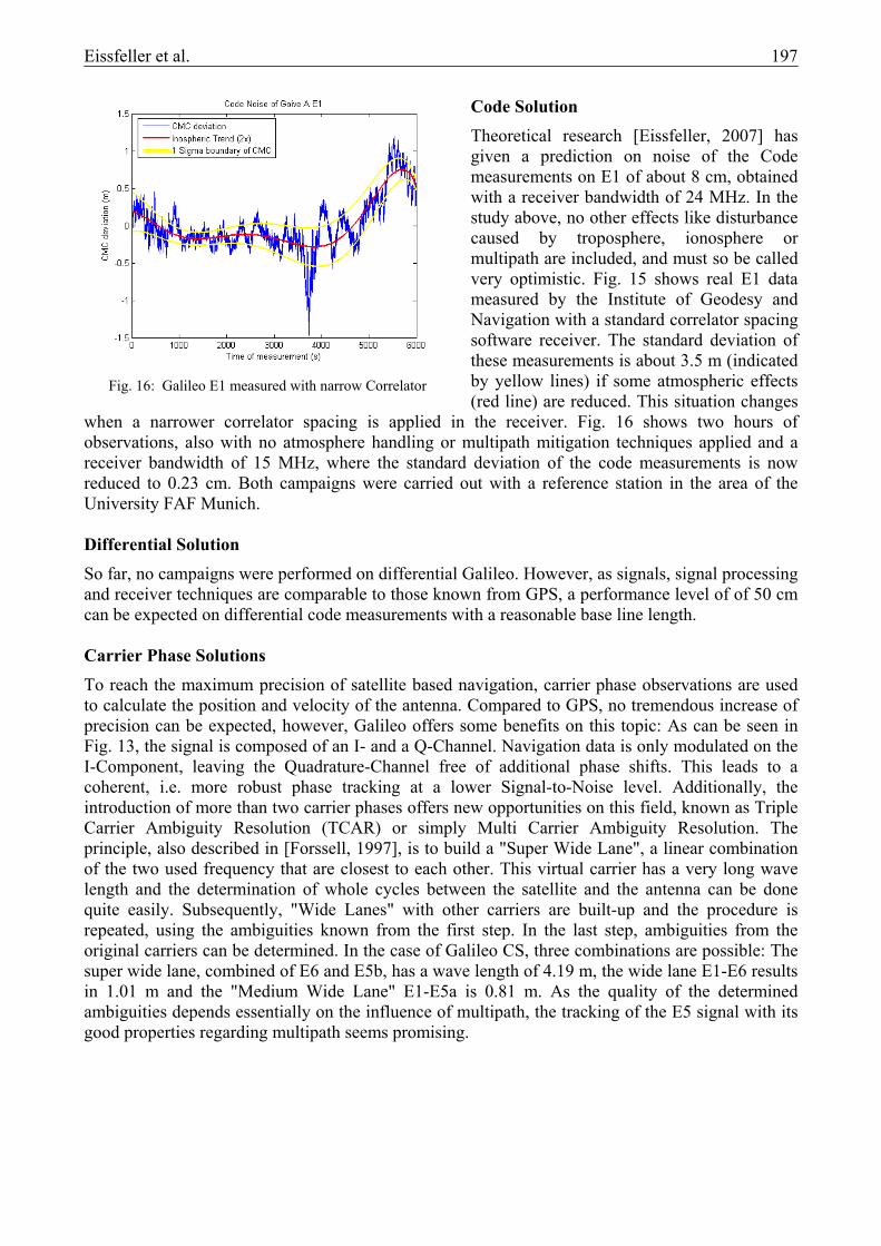
Code Solution Theoretical research [Eissfeller, 2007] has given a prediction on noise of the Code measurements on E1 of about 8 cm, obtained with a receiver bandwidth of 24 MHz. In the study above, no other effects like disturbance caused by troposphere, ionosphere or multipath are included, and must so be called very optimistic. Fig. 15 shows real E1 data measured by the Institute of Geodesy and Navigation with a standard correlator spacing software receiver. The standard deviation of these measurements is about 3.5 m (indicated by yellow lines) if some atmospheric effects (red line) are reduced. This situation changes
when a narrower correlator spacing is applied in the receiver. Fig. 16 shows two hours of observations, also with no atmosphere handling or multipath mitigation techniques applied and a receiver bandwidth of 15 MHz, where the standard deviation of the code measurements is now reduced to 0.23 cm. Both campaigns were carried out with a reference station in the area of the University FAF Munich. Differential Solution So far, no campaigns were performed on differential Galileo. However, as signals, signal processing and receiver techniques are comparable to those known from GPS, a performance level of of 50 cm can be expected on differential code measurements with a reasonable base line length. Carrier Phase Solutions To reach the maximum precision of satellite based navigation, carrier phase observations are used to calculate the position and velocity of the antenna. Compared to GPS, no tremendous increase of precision can be expected, however, Galileo offers some benefits on this topic: As can be seen in Fig. 13, the signal is composed of an I- and a Q-Channel. Navigation data is only modulated on the I-Component, leaving the Quadrature-Channel free of additional phase shifts. This leads to a coherent, i.e. more robust phase tracking at a lower Signal-to-Noise level. Additionally, the introduction of more than two carrier phases offers new opportunities on this field, known as Triple Carrier Ambiguity Resolution (TCAR) or simply Multi Carrier Ambiguity Resolution. The principle, also described in [Forssell, 1997], is to build a "Super Wide Lane", a linear combination of the two used frequency that are closest to each other. This virtual carrier has a very long wave length and the determination of whole cycles between the satellite and the antenna can be done quite easily. Subsequently, "Wide Lanes" with other carriers are built-up and the procedure is repeated, using the ambiguities known from the first step. In the last step, ambiguities from the original carriers can be determined. In the case of Galileo CS, three combinations are possible: The super wide lane, combined of E6 and E5b, has a wave length of 4.19 m, the wide lane E1-E6 results in 1.01 m and the "Medium Wide Lane" E1-E5a is 0.81 m. As the quality of the determined ambiguities depends essentially on the influence of multipath, the tracking of the E5 signal with its good properties regarding multipath seems promising.
Fig. 16: Galileo E1 measured with narrow Correlator

198 Eissfeller et al.
Conclusions Galileo is not yet available, but it has already influenced the accelerated modernization of GPS and GLONASS. The introduction of 30 new satellites, that can be processed almost in the same way as GPS will result in better geometry and availability. The new service model of Galileo, introducing mechanisms like "Integrity" and "Authentication", not only provided by Satellite Based Augmentation Systems (SBAS), but by the navigation satellite themselves worldwide, will at least lead to a revision of the navigation systems that are used nowadays.
5. SUMMARY
The modernization of the three described GNSS will drive satellite based navigation more and more into a mass market application. Together with other information sources like Cell based navigation used e.g. in telecommunication systems, Micro-Electro-Mechanical System IMU (MEMS-IMU) as seen in the Nintendo Wii and perhaps map guided navigation, GNSS will find its applications in hand-held devices or cell-phones. On the geodetic level, the use of three modern GNSS systems will reduce observation time and make measurements more precise. The PDOP world-wide distribution is reduced dramatically, providing values less than 2 and eliminating peaks. Situation will change again, if one makes use of the modernized GLONASS with its 30 additional satellites. Even if the precision is limited for effects like ionospheric delays or low-level receiver clocks, the availability of services and robustness of algorithms is an argument for GNSS. Carrier Ambiguity Resolution can be performed better and more reliable if three (TCAR) of more (MCAR) carrier frequencies are used in the algorithms.
6. REFERENCES
Books and Journals:
[Ballenger, 2005], Col. Allan Ballenger, "GPS Program Update", 15 CGSIC
[Crews, 2007], Col. Mark Crews, "GPS Wing Program Update", Munich Satellite Navigation Summit 2007
[EC, 1999], European Commission: Galileo, "Involving Europe in a New Generation of Satellite Navigation Services", Communication 54, Brussels, 9. February, 1999
[Eissfeller, 2007], Eissfeller, B., M. Irsigler, J. Avila-Rodriguez, E. Schüler, T. Schüler: "Das europäische Satellitennavigationssystem Galileo – Entwicklungsstand", AVN - Allgemeine Vermessungsnachrichten, No. 02/2007, pp. 42-55, Wißner-Verlag, Germany, Wißner-Verlag
[Forssell, 1997], Forssell, B., Martin-Neira, M., Harris, R.A.: "Carrier Phase Ambiguity Resolution in GNSS-2"; Proceedings of the ION GPS-97, 10th International Technical Meeting of The Satellite Division of The Institute of Navigation, Kansas City Convention Center, Kansas City, Missouri, 16.-19. September 1997, pp. 1727-1736

Eissfeller et al. 199
[Hein, 2005], Guenter W. Hein, C. Kreye und B. Zimmerman, "Entwicklung und Testergebnisse eines Systems zur vektoriellen Fluggravimetrie auf Basis eines kommerziellen, hochpräzisen Strapdown INS", Final report of the project "Entwicklung der Fluggravimetrie unter Nutzung von GNSS Satellitenbeobachtungen" promoted by BMBF and DFG within the Programm "Geotechnologien"
[Hein, 2007], Guenter W. Hein, "Current GPS and GLONASS"
[Hein, 2006], Hein, G. W. et al.: "MBOC: The New Optimized Spreading Modulation Recommen-ded for Galileo L1 OS and GPS L1C", Proceedings of ION PLANS 2006, 24.-27. April 2006, Loews Coronado Bay Resort, San Diego, California
[ICDGLON], ICD-GLONASS (1995). GLONASS Interface Control Document (Rev. 1995). Coordinational Scientific Information Center Russian Space Forces, Moscow. English Translation of Russian Document.
[Misra, 2001], Patrap Misra and Per Enge, "Global Positioning System: signals, measurements, and performance", Ganga-Jamuna Press 2001
[Rossbach, 1996], Roßbach, U. and Hein, G. W. (1996b). "Treatment of Integer Ambiguities in DGPS/DGLONASS Double Difference Carrier Phase Solutions". Proceedings of ION Satellite Division GPS-96 International Technical Meeting, pp. 909-916, Kansas City, Missouri.
[Turner, 2006], David A. Turner, "Space-Based PNS Modernization Update", Munich Satellite Navigation Summit 2006
[Wallner, 2006], Wallner, S., Avila-Rodriguez, J.A., Hein, G. W.: "Interference Computations between Several GNSS Systems", ESA Navitec 2006, Noordwijk, The Netherlands, Dec. 11-13, 2006
[Weber, 2001], Weber, T., Trautenberg, H. L., Schäfer, Chr.: "Galileo System Architecture – Status and Concepts", Proceedings ION GPS 2001, Salt Lake City
www:
[WWWGLON], http://www.glonass-ianc.rsa.ru/
[summit07], http://www.munich-satellite-navigation-summit.org/Documentation/ Summary07Session4.pdf