
Ammonia process - BAT Production of ammonia (2000) - Brochure.pdf

warwick.ac.uk/lib-publications
Original citation: van der Pal, Michel and Critoph, Robert E.. (2017) Performance of CaCl 2 -reactor for application in ammonia-salt based thermal transformers. Applied Thermal Engineering, 126 . pp. 518-524. Permanent WRAP URL: http://wrap.warwick.ac.uk/92322 Copyright and reuse: The Warwick Research Archive Portal (WRAP) makes this work of researchers of the University of Warwick available open access under the following conditions. This article is made available under the Creative Commons Attribution 4.0 International license (CC BY 4.0) and may be reused according to the conditions of the license. For more details see: http://creativecommons.org/licenses/by/4.0/ A note on versions: The version presented in WRAP is the published version, or, version of record, and may be cited as it appears here. For more information, please contact the WRAP Team at: [email protected]

Applied Thermal Engineering 126 (2017) 518–524
Contents lists available at ScienceDirect
Applied Thermal Engineering
journal homepage: www.elsevier .com/locate /apthermeng
Research Paper
Performance of CaCl2-reactor for application in ammonia-salt basedthermal transformers
http://dx.doi.org/10.1016/j.applthermaleng.2017.07.0861359-4311/� 2017 The Authors. Published by Elsevier Ltd.This is an open access article under the CC BY license (http://creativecommons.org/licenses/by/4.0/).
⇑ Corresponding author at: Energy Research Centre of the Netherlands (ECN),Westerduinweg 3, Petten 1755 LE, The Netherlands.
E-mail address: [email protected] (M. van der Pal).
Michel van der Pal a,b,⇑, Robert E. Critoph b
a Energy Research Centre of the Netherlands (ECN), Westerduinweg 3, Petten 1755 LE, The NetherlandsbUniversity of Warwick, Library Road, Coventry CV4 7AL, United Kingdom
a r t i c l e i n f o
Article history:Received 8 March 2017Revised 10 July 2017Accepted 11 July 2017Available online 13 July 2017
Keywords:AdsorptionHeat pumpThermochemicalAmmonia
a b s t r a c t
Thermochemical reactions, such as calcium chloride reacting with ammonia to form calcium chloridecomplexes, are attractive for application in heat pumps as they produce more heat per kg adsorbed sor-bate but also adsorb a considerable higher amount of sorbate per kg of sorbent, compared to adsorbentssuch as zeolites. These benefits, however, come with together with a number of challenges. Firstly, thesalts have poor thermal conductivity so the path from heat exchanger to the sorbent must be limitedin order to allow for short cycling times and therefore high power density. Secondly, the salts typicallyswell and shrink upon (de)sorption, thereby easily losing their contact with the heat exchanger. To over-come these two problems, the salts are often placed in a matrix, such as expanded natural graphite (ENG)or zeolites.This paper shows the performance of a reactor containing approximately 1 kg of CaCl2 placed in a 1 kg
ENG matrix. Its performance in terms of adsorption/desorption rates, heat input and output as a functionof temperature and pressure gradients and under typical heat pump and transformer conditions is shownand compared with model calculations. The parameters used in the model calculations have beenobtained from literature or independently measured using apparatus such as Rubotherm microbalanceand a large temperature jump setup. The results show that material properties measured on small sam-ples do not easily yield a proper description of the sorbent performance on kW-scale reactors. Some sug-gestions are made to improve future model description and experiments.� 2017 The Authors. Published by Elsevier Ltd. This is an openaccess article under the CCBY license (http://
creativecommons.org/licenses/by/4.0/).
1. Introduction
Thermally driven heat pumps and transformers can contributesignificantly to reducing our carbon footprint. Various types ofthermally driven heat pumps and transformers can be found in lit-erature, each with their own benefits and challenges. In this paperwe focus on the development of thermally driven system usingthermochemical reactions. These are reactions between a sorbate(e.g. ammonia) and a sorbent (e.g. CaCl2) in which heat is releasedwhen combined and heat is extracted when separated.
Although a considerable amount of research has been done [1–4], few or no commercial thermochemical systems are currentlyavailable. The main challenge is to achieve stable performancewith sufficiently high power density to allow for reasonably com-pact and affordable systems. In the past, the Energy Research Cen-tre of the Netherlands (ECN) has built several prototypes using
various heat exchanger designs but each had their own problemspreventing further development to a commercial product. Afterthese setbacks, it was decided to develop a unit in which reactorelements could be tested before building an entire reactor andsystem.
The work presented in this paper takes one of the concepts thatwas successfully tested in the aforementioned setup and placed itinside a 10 kW scale reactor for testing. It describes the perfor-mance of a reactor based on CaCl2 impregnated in ENG. The mea-surements are subsequently compared to model calculationsusing thermal conductivity and reaction kinetics data from sepa-rate measurements or literature sources.
Fig. 1 shows earlier prototypes of thermochemical heat trans-formers developed at ECN. The first prototype (left) containedfinned tube heat exchanger with a packed bed of salt. Probablydue to swelling of the salt the ammonia could not be cycled at asufficient rate. A second prototype was built (middle) where saltwas deposited in a metal-foam placed on a sandwich plate throughwhich thermal oil was flowing. This system had two major prob-lems: the first one was the enormous thermal mass of the system,
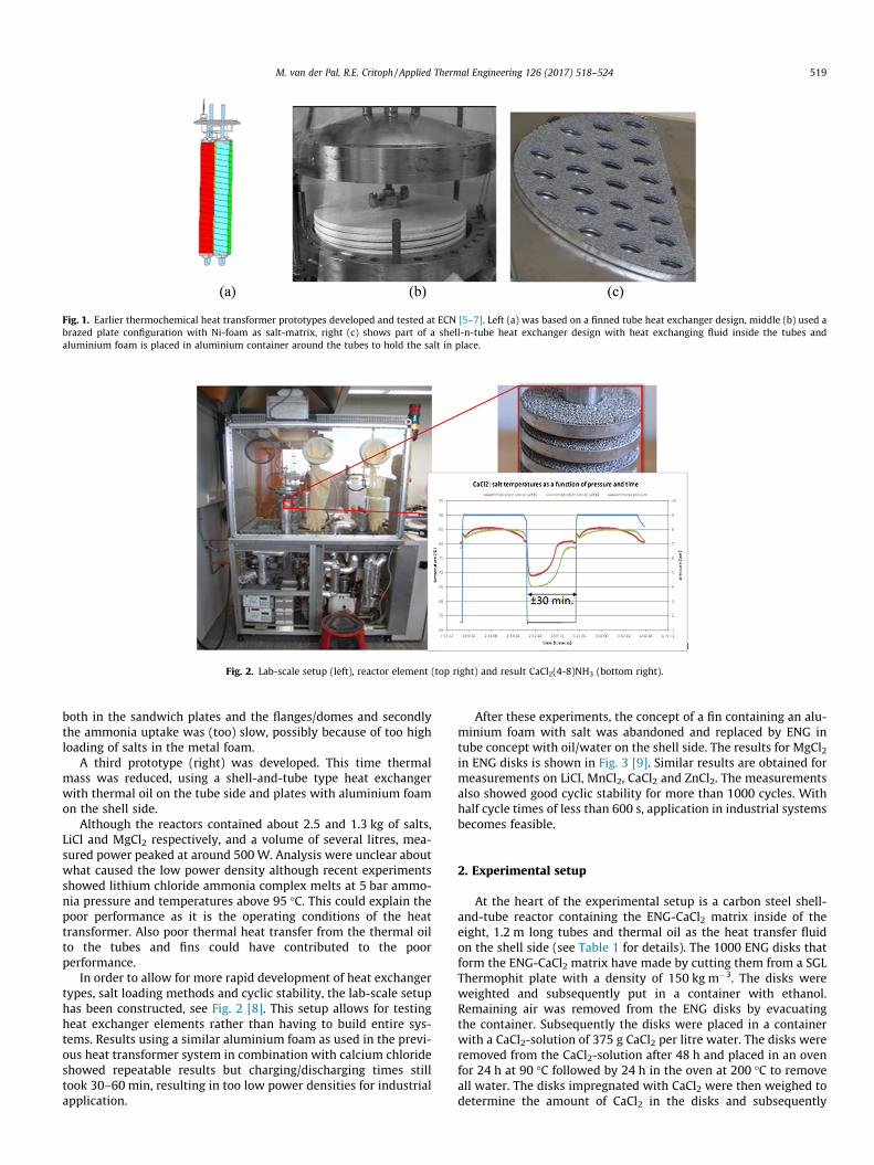
Fig. 1. Earlier thermochemical heat transformer prototypes developed and tested at ECN [5–7]. Left (a) was based on a finned tube heat exchanger design, middle (b) used abrazed plate configuration with Ni-foam as salt-matrix, right (c) shows part of a shell-n-tube heat exchanger design with heat exchanging fluid inside the tubes andaluminium foam is placed in aluminium container around the tubes to hold the salt in place.
Fig. 2. Lab-scale setup (left), reactor element (top right) and result CaCl2(4-8)NH3 (bottom right).
M. van der Pal, R.E. Critoph / Applied Thermal Engineering 126 (2017) 518–524 519
both in the sandwich plates and the flanges/domes and secondlythe ammonia uptake was (too) slow, possibly because of too highloading of salts in the metal foam.
A third prototype (right) was developed. This time thermalmass was reduced, using a shell-and-tube type heat exchangerwith thermal oil on the tube side and plates with aluminium foamon the shell side.
Although the reactors contained about 2.5 and 1.3 kg of salts,LiCl and MgCl2 respectively, and a volume of several litres, mea-sured power peaked at around 500W. Analysis were unclear aboutwhat caused the low power density although recent experimentsshowed lithium chloride ammonia complex melts at 5 bar ammo-nia pressure and temperatures above 95 �C. This could explain thepoor performance as it is the operating conditions of the heattransformer. Also poor thermal heat transfer from the thermal oilto the tubes and fins could have contributed to the poorperformance.
In order to allow for more rapid development of heat exchangertypes, salt loading methods and cyclic stability, the lab-scale setuphas been constructed, see Fig. 2 [8]. This setup allows for testingheat exchanger elements rather than having to build entire sys-tems. Results using a similar aluminium foam as used in the previ-ous heat transformer system in combination with calcium chlorideshowed repeatable results but charging/discharging times stilltook 30–60 min, resulting in too low power densities for industrialapplication.
After these experiments, the concept of a fin containing an alu-minium foam with salt was abandoned and replaced by ENG intube concept with oil/water on the shell side. The results for MgCl2in ENG disks is shown in Fig. 3 [9]. Similar results are obtained formeasurements on LiCl, MnCl2, CaCl2 and ZnCl2. The measurementsalso showed good cyclic stability for more than 1000 cycles. Withhalf cycle times of less than 600 s, application in industrial systemsbecomes feasible.
2. Experimental setup
At the heart of the experimental setup is a carbon steel shell-and-tube reactor containing the ENG-CaCl2 matrix inside of theeight, 1.2 m long tubes and thermal oil as the heat transfer fluidon the shell side (see Table 1 for details). The 1000 ENG disks thatform the ENG-CaCl2 matrix have made by cutting them from a SGLThermophit plate with a density of 150 kg m�3. The disks wereweighted and subsequently put in a container with ethanol.Remaining air was removed from the ENG disks by evacuatingthe container. Subsequently the disks were placed in a containerwith a CaCl2-solution of 375 g CaCl2 per litre water. The disks wereremoved from the CaCl2-solution after 48 h and placed in an ovenfor 24 h at 90 �C followed by 24 h in the oven at 200 �C to removeall water. The disks impregnated with CaCl2 were then weighed todetermine the amount of CaCl2 in the disks and subsequently

Fig. 3. Small-scale lab setup results for reaction time as a function of relative pressure ratio defined as Papplied/Peq(Tsalt) � 1, for 10 g MgCl2 in ENG [9]. The measurements havebeen conducted for a range of temperatures (120–180 �C) and pressures (3–8 bar). The reaction time has been defined as the amount of time required to reach 90% of the totalamount ammonia adsorbed for MgCl2(2-6)NH3 reaction.
Table 1Reactor and sorbent properties.
Property Value
Weight ENG 870 gWeight CaCl2 927 gInner diameter tubes 28 mmOuter diameter tubes 31.6 mm (1¼00)Diameter shell 152 mm (600)Volume tube-side 5.9 dm3
Volume shell-side 11.2 dm3
Length tube 1.2 m per tubeNumber of tubes 8Heat transfer fluid OilConnection shell side 18.9 mm (¾00)Connection tube side 12.1 mm (½00)
1 For interpretation of color in Fig. 6, the reader is referred to the web version ofis article.
520 M. van der Pal, R.E. Critoph / Applied Thermal Engineering 126 (2017) 518–524
placed in the reactor whilst minimizing exposure to ambient air toavoid hydration of the calcium chloride.
The reactor is connected to the so-called ThermExS facility thatsupplies or extract heat as shown in Fig. 4. The ammonia is sup-plied using a shell-and-tube type evaporator, and removed usinga plate heat exchanger type condenser, both capable of providing10+ kW evaporator/condenser power. The reactor, condenser andevaporator can be set to a desired temperature using Huber ther-mostatic baths. The flow of ammonia is controlled by openingthe valves between the reactor and the evaporator and condenser.Typically the reactor is varied between two temperatures (andpressures) while the evaporator and condenser are kept at a con-stant temperature and pressure. The latter allows for accuratemeasurement of heat fluxes to/from the condenser and evaporator.For the equilibrium measurements the valves between the reactorand the evaporator/condenser were closed to maintain the state ofthe calcium chloride ammonia complex.
The measured parameters include mass flow of the thermal oil,water and glycol, the temperatures of fluid entering and leavingthe reactor, evaporator and condenser and the ammonia pressuresin these components. Also a temperature sensor has been insertedin the ENG disks to measure the temperature of the salt-ENG com-posite. The pressure measurement is accurate to 0.5% F.S. and thethermocouples are within 0.1 K accurate compared in relation tothe reference temperature. Heat flows to/from the different com-ponents are calculated using the mass flows, heat capacity andtemperatures. Pressure is measured in the reactor and the con-denser and evaporator.
3. Results
3.1. Equilibrium measurements
Fig. 5 shows the result of the measurement of the (quasi) equi-librium between pressure and temperature by increasing and sub-sequently decreasing the reactor temperature in steps of 10 Kwhilst the connections to evaporator and condenser remainedclosed. The right graph shows the measured pressure – tempera-ture relation in comparison with the theoretical correlation basedon the Claussius-Clapeyron equation with the DS and DH datafor the reactions as shown in Table 2. As can be seen from the rightgraph, the measured data (blue line) correlates very well with thetheoretical P-T relation for the CaCl2(4-8)NH3 reaction (green line)based on the measured salt temperature (Tsalt). This means hys-teresis is negligible and that the thermocouple placed in theENG-salt composite yields a representative value for the salt tem-perature. For the CaCl2(4-2)NH3 reaction (not shown) a minor devi-ation (<5 K) is found, likely due to (slow) reaction kinetics.
Claussius-Clapeyron equation:
P ¼ P0e�DH�TDS
RT ð1Þ
3.2. Dynamic measurements
Fig. 6 shows an example of a dynamic measurement of the des-orption of ammonia from the CaCl2-ENG composite by heating thereactor from 40 �C to 130 �C with a condenser temperature of 40 �C(16 bar NH3) and a evaporator temperature of �10 �C (3 bar NH3).The blue1 line shows the salt temperature, which increases from40 �C to 130 �C. The green and red lines show the equilibrium tem-peratures for respectively the CaCl2(8-4)NH3 and the CaCl2(4-2)NH3 reaction based on the pressure in the reactor. The purple lineshows the power measured on the condenser (Qcond), calculatedfrom the difference in temperature in/out of the condenser and theflowrate of the water.
A rapid increase in salt temperature can be observed between500 and 1000 s. The salt temperature remains near the tempera-ture associated with the equilibrium condition for the desorptionreaction of CaCl2(8-4)NH3 for the measured ammonia pressure
th

Fig. 4. Reactor filled with ENG-CaCl2 disks connected to ThermExSrig facility for supplying/extracting heat and ammonia. The evaporator is connected to a glycol loop, thecondenser to a water loop and the reactor to a thermal oil loop.
Fig. 5. Left (a) shows on the left-axis the measured temperatures for respectively oil entering/leaving the reactor and ENG-CaCl2 in reactor (blue, red, green lines) and on theright axis the measured ammonia pressure (purple) in the reactor as a function of time. Right (b) shows the measured ammonia pressure (blue line) as a function of CaCl2-ENGtemperature together with the theoretical pressure-temperature relation for CaCl2(2-4)NH3 (red line) and for CaCl2(4-8)NH3 (green line) based on Claussius-Clapeyron Eq. (1).(For interpretation of the references to colour in this figure legend, the reader is referred to the web version of this article.)
Table 2Entropy and enthalpy values for CaCl2(2-4)NH3 and CaCl2(4-8)NH3 reactions [10]
CaCl2(2-4)NH3 CaCl2(4-8)NH3
DH (J mol�1) 42100 42100DS (J mol�1 K�1) 134.1 139.0
M. van der Pal, R.E. Critoph / Applied Thermal Engineering 126 (2017) 518–524 521
(�16 bar) whilst the condenser power shows peak power of1.6 kW. The salt temperature rises further to about 110 �C foranother 500 s after which the condenser power returns to zero,indicating the desorption reaction has finished. The salt tempera-ture rises further until it reaches the (set) temperature of the ther-mal oil (130 �C). At t = 3000 s the reactor and thereby the salt iscooled down again to start adsorption of ammonia again. The tem-perature profile and the condenser power both indicate a two-stepreaction, suggesting a first desorption step of CaCl2(8-4)NH3 and asecond desorption step of CaCl2(4-2)NH3. After the second desorp-
tion the temperature of the reactor and the salt increases furthertill it reached the temperature of the thermal oil (130 �C).
3.3. Model calculations
Dynamic measurements have been modelled using a 1-D Mat-lab model that includes heat transfer resistance from reactor wallto the ENG-CaCl2 composite, thermal conductivity through thecomposite and kinetic behaviour of the sorbent. The input param-eters are shown in Table 3 and have been obtained from indepen-dent measurements or literature sources. The following mainequations have been used to model the sorption process.Heattransfer from thermal oil to composite material:
dQdt
¼ U � AtubeðToil � TwallÞ ð2Þ
Heat transfer & production at position i in composite material:

Fig. 6. Dynamic measurement of salt temperature (Tsalt) and condenser power (Qcond) as a function of time. T(2-4)@Preactor and T(4-8)@Preactor are the temperaturesassociated for the reactor pressure in equilibrium for respectively CaCl2(2-4)NH and CaCl2(4-8)NH3 reaction and has been calculated by using a rearranged version of Eq. (1):T ¼ DH
DS�R ln PP0
.
Table 3Main input parameters for the Matlab model calculations.
Parameter Value Source
Pressure in reactor 9 bar Experimental conditionsInitial temperature (t = 0) 40 �CDesorption temperature
(t > 0)130 �C
Thermal conductivity ENG 6Wm�1 K�1 Data SGL CarbonHeat transfer coefficient
oil to ENG50/100/200Wm�2 K�1
Estimated range accordingto literature
Kinetic rate constantCaCl2(8-4)NH3
0.04 s�1 [11]
Kinetic rate constantCaCl2(4-2)NH3
0.04 s�1 [11]
522 M. van der Pal, R.E. Critoph / Applied Thermal Engineering 126 (2017) 518–524
dQi
dt¼ �kAi
dTi
dxþ DH84 � dn84
dtþ DH42 � dn42
dtð3Þ
Reaction rates at position i in composite material:
dn84
dt¼ k84 � P84ðTiÞ � Preactor
Preactorð4Þ
dn42
dt¼ k42 � P42ðTiÞ � Preactor
Preactorð5Þ
Temperature change at position i in composite material:
dTi
dt¼ 1
Ai � dx � q � Cp� dQi
dtð6Þ
where:
Atube
surface area of inner tube in contact with compositematerial (m2)Ai
surface area of composite at position i perpendicularto heat flow (m2)Cp
heat capacity of composite material (J g�1 K�1)dx
length of element in direction of heat flow (m) k84 kinetic constant reaction CaCl2(8-4)NH3 (s�1) k42 kinetic constant reaction CaCl2(4-2)NH3 (s�1) n84 fraction of reaction CaCl2(8-4)NH3 completed (valuefrom 0 to 1)
n42 fraction of reaction CaCl2(4-2)NH3 completed (valuefrom 0 to 1)
Preactor ammonia pressure in reactor (bar) P84(Ti) equilibrium pressure for CaCl2(8-4)NH3 reaction attemperature Ti (bar)
P42(Ti) equilibrium pressure for CaCl2(4-2)NH3 reaction attemperature Ti (bar)
Q heat transferred from tube to composite material (J) Qi heat at position i in composite material (J) t time (s) Toil temperature of thermal oil (K) Ti temperature of composite material at position i (K) Twall temperature of composite material at wall (K) U heat transfer coefficient from oil to compositematerial (Wm�2 K�1)
DH84 total heat of sorption for CaCl2(8-4)NH3 at position i(J)
DH42 total heat of sorption for CaCl2(4-2)NH3 at position i(J)
k thermal conductivity of composite material(Wm�1 K�1)
q density of composite material (g m�3)Fig. 7 shows the calculated amount of ammonia desorbed for arange of heat transfer coefficients together with the amount basedon measured condenser power. It can be observed that the mea-sured amount of ammonia is about 10% less than the amount thatcould theoretically be desorbed. It can also be seen that a heattransfer coefficient of 100Wm�2 K�1 shows a good correlation withmeasured data. The temperature profiles from the model calcula-tions have a reasonable correlation with the measured values (left

Fig. 7. Amount of desorbed ammonia (g NH3 per g CaCl2) measured value (black line) and values based on model calculations using heat transfer coefficients of respectively50 (blue line), 100 (red line) and 200 (yellow line) Wm�2 K�1 as a function of time. (For interpretation of the references to colour in this figure legend, the reader is referred tothe web version of this article.)
Fig. 8. Temperatures at five locations from model calculations as a function of time with original (left) and a 5-times reduced (right) reaction kinetics for the CaCl2(4-2)NH3
reaction and assuming 100Wm�2 K�1 heat transfer coefficient for both cases. The bold black line shows the measured temperature profile as function of time.
M. van der Pal, R.E. Critoph / Applied Thermal Engineering 126 (2017) 518–524 523
graph of Fig. 8) and a good correlation when a 5-times smallerkinetic rate constant is used for the CaCl2(4-2)NH3 reaction (rightgraph of Fig. 8).
4. Discussion
Measurements on reactor show good correlation with equilib-rium conditions for the CaCl2(8-4)NH3 reaction, both adsorptionand desorption. Therefore the driving force for the desorption of
ammonia from CaCl2 can be limited to heat transfer limitations,due to transfer of heat from thermal oil to the composite materialand within the composite material itself, and limitations in reac-tion kinetics. Model calculations show a good correlation withmeasurements, both in terms of rate of uptake (Fig. 7) as well asthe temperature profile measured and modelled (Fig. 8) provideda slight limitation is introduced on the reaction kinetics of theCaCl2(4-2)NH3 reaction. The latter is contradicting the large tem-perature jump measurements conducted on CaCl2 by Jegede [2]

524 M. van der Pal, R.E. Critoph / Applied Thermal Engineering 126 (2017) 518–524
that showed equal kinetic rate constants for both reactions. Thephenomenon could be future investigated by conducting moreexperiments over a larger range of ammonia pressures and salttemperatures. Given the small difference in measured temperatureand equilibrium temperature for the CaCl2(8-4)NH3 reaction,improving the heat transfer rate from the heat transfer fluid tothe composite material is expected to have a large positive effecton the rate of reaction and thereby reducing the cycle time signif-icantly. This improvement can be achieved by either increasing theheat transfer surface area (per kg of sorbent) which can be done byusing smaller diameter tubes and/or by replacing the thermal oilby water or steam as heat exchanging medium. A factor of 4increase in heat transfer coefficient can be expected for the heattransfer medium. The overall effect can be smaller as the currentvalue also includes the transfer of heat through the tube to thecomposite material.
Despite the limitations on heat transfer, a desorption rate ofabout 800 g NH3 in 800 s has been observed. Given the typicalsorption enthalpy of 2.5 kJ/g NH3 for ammonia salts for a resorp-tion, thermal transformer system, this is equal to 2.5 kW sorptionheat for the reactor or a power density of 420 kW per m3 sorbentvolume. Efficiency of a thermal transformer based on the currentreactor is very low (COP < 0.1) because about 75% of sorption heatis required for a 50 K temperature rise of the reactor itself. This,however, is mainly due to the large thermal mass of the shell,headers and the flanges that connects them. For large-scale, indus-trial application the thermal mass of the shell and headers com-pared to the sorption heat will be considerably less. Also thethermal of the heat exchanging medium can be reduced by havinga more compact design of the tubes. Finally, thermal transformercan be executed as a four-bed system with heat recovery betweenthe beds. Overall it is estimated a full-scale thermal transformerupgrading waste heat of 130–180 �C process heat can reach aCOP between 0.35 and 0.40 where a COP of 0.50 is (roughly) themaximum achievable value for a resorption-based thermal trans-former. Before constructing a bench-scale prototype thermal trans-former, it is recommended to verify performance of the hightemperature ammonia-salts in a similar reactor as presented inthis paper to verify no hysteresis occurs and the performance isnot limited by reaction kinetics or thermal conductivity in the saltmatrix.
5. Conclusions
� CaCl2 in ENG shows little to no hysteresis for the CaCl2(4-8)NH3
reaction, both in the adsorption and desorption process.� There is a good correlation between the model calculations andmeasurements on desorption rate of ammonia from CaCl2�8NH3
� Contrary to previous study, kinetic rate constants seem differ-ent for CaCl2(8-4)NH3 and CaCl2(4-2)NH3 reactions.
� Desorption rate of the reactor is limited by heat transfer fromthe thermal oil to the ENG-salt matrix, likely related to the poorheat transfer properties of the thermal oil, rather than reactionkinetics or thermal conductivity of the salt matrix.
� Outlook for reasonable performance of thermal transformer(COP = 0.35–0.40) when reactor is scaled to industrial size.
Acknowledgements
This research is supported by the EU-H2020 INTERACT-projectwith grant-number DLV-659749 and EPSRC Grant: ThermExS Lab-oratory EP/L018098/1.
References
[1] Y.I. Aristov, Challenging offers of material science for adsorption heattransformation: a review, Appl. Thermal Eng. 50 (2013) 1610–1618.
[2] R. Dunn, K. Lovegrove, G. Burgess, A review of ammonia-basedthermochemical energy storage for concentrating solar power, Proc. IEEE 100(2012) 391–400.
[3] B. Spinner, Ammonia salts thermochemical heat transformation, in:Proceedings of the Symposium on Solid Sorption Refrigeration, Paris,November 18–20, 1992, pp. 163–169.
[4] Ph. Touzain, M. Moundanga-Iniamy, Thermochemical heat transformation:Study of the ammonia/magnesium chloride – GIC pair in a laboratory pilot,Mol. Cryst. Liq. Cryst. 245 (1994) 243–248.
[5] R.J.H. Grisel, S.F. Smeding, J.B.J. Veldhuis, W.G. Haije. De hoge temperatuurchemische warmtetransformator: I. Thermodynamische data enwarmtetransport, in: ECN-CX–03-072003.
[6] W.G. Haije, J.B.J. Veldhuis, S.F. Smeding, R.J.H. Grisel, Solid/vapour sorptionheat transformer: design and performance, Appl. Thermal Eng. 27 (2007)1371–1376.
[7] M. van der Pal, R. de Boer, J. Veldhuis, S. Smeding, Thermally driven ammonia-salt type ii heat pump: development and test of a prototype, in: Proceedings ofthe Heat Powered Cycles Conference 2009, Berlin 7–9 sept, 2009 [320], 2009.
[8] M. van der Pal, R. de Boer, J. Veldhuis, S. Smeding, Experimental setup fordetermining ammonia-salt adsorption and desorption behavior under typicalheat pump conditions: a description of the setup and experimental results, in:ISHPC 2011, Proceedings of the International Sorption Heat Pump Conference2011, April 6–8, Padua, Italy, 2011.
[9] M. van der Pal, R. de Boer, J. Veldhuis, Experimental setup for determiningammonia-salt adsorption and desorption behavior under typical heat pumpconditions: experimental results, in: B. B. Saha, M. Koyama, Y. Takata, Y.Hamamoto, T. Miyazaki, M. Kohno, K. Ito (Eds.), International Symposium onInnovative Materials for Processes in Energy Systems 2013. IMPRES 2013,International Symposium on Innovative Materials for Processes in EnergySystems 2013, Kyushu, 2013, pp. 483–488.
[10] Ph. Touzain, Thermodynamic values of ammonia-salt reactions for chemicalsorption heat pumps, in: C. Schweigler, S. Summerer, H.-M. Hellmann, F.Ziegler (Eds.), Proceedings of the International Sorption Heat PumpConference, Munich, Germany, March 24–26, 1999, Garching, ZAE Bayern.ISHPC – International Sorption Heat Pump Conference, 1999, pp. 225–238.
[11] O.O. Jegede, R.E. Critoph, Extraction of heat transfer parameters in activecarbon–ammonia large temperature jump experiments, Appl. Therm. Eng. 95(2016) 499–505.