Performance of Bolted Joints In Douglas-Fir · procedures for bolted joints are technically sound...
48
Performance of BOLTED JOINTS IN DOUGLAS-FIR U.S. FOREST SERVICE RESEARCH PAPER FPL 2 MAY 1963 FOREST PRODUCTS LABORATORY U.S. DEPARTMENT OF AGRICULTURE FOREST SERVICE - MADISON, WIS.
Transcript of Performance of Bolted Joints In Douglas-Fir · procedures for bolted joints are technically sound...
Performance of BOLTED JOINTS IN DOUGLAS-FIR
U.S. FOREST SERVICE
RESEARCH PAPER
FPL 2 MAY 1963
FOREST PRODUCTS LABORATORY U.S. DEPARTMENT OF AGRICULTURE FOREST SERVICE - MADISON, WIS.

This U.S. Forest Service Research Paper, FPL 2, is the second in a new series issued by the Forest Products Laboratory describing research results and developments.
SUMMARY
The strength and behavior of machine bolts in timber joints with wood and metal side plates were evaluated by subjecting three-member joints with one and four bolts to lateral loads bearing either parallel or perpendicular to the grain in the wood center member of the joint. Joints were made with 3/4-inch bolts in lumber at three stages of seasoning and with 1/2-, 3/4-, and 1-inch bolts in nominal 3-inch-thick Douglas-fir dry lumber.
The results of this study indicate that current design procedures for bolted joints are technically sound insofar as this study applies. The bearing stresses on a per-bolt basis for the four-bolt joints were about 10 percent lower than those for single-bolt joints with bolts bearing parallel to the grain.
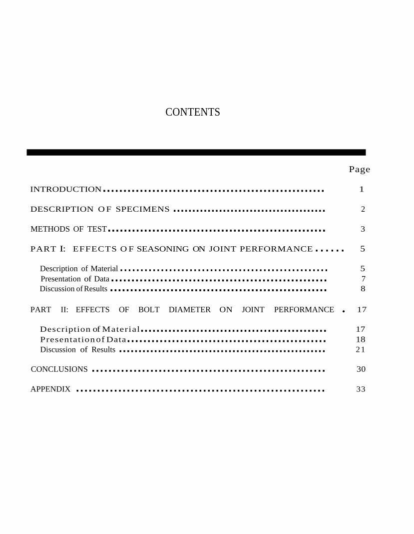
CONTENTS
Page
INTRODUCTION...................................................... 1
DESCRIPTION O F SPECIMENS ........................................ 2
METHODS OF TEST...................................................... 3
PART I: EFFECTS O F SEASONING ON JOINT PERFORMANCE ...... 5
Description of Material ................................................... 5 Presentation of Data..................................................... 7 Discussion of Results ...................................................... 8
PART II: EFFECTS OF BOLT DIAMETER ON JOINT PERFORMANCE . 17
Description of Material............................................... 17 Presentation of Data................................................. 18 Discussion of Results ..................................................... 21
CONCLUSIONS ........................................................ 30
APPENDIX ........................................................... 33
PERFORMANCE OF BOLTED JOINTS IN DOUGLAS-FIR
By DONALD V. DOYLE and JOHN A. SCHOLTEN, Engineer
Forest Products Laboratory,1 Forest Service
U.S. Department of Agriculture
INTRODUCTION
This report presents the results of experimental research conducted at the Forest Products Laboratory to study the strength and behavior of bolts in Douglas-fir lumber. The factors investigated included one-bolt and four-bolt joints, loading either parallel or perpendicular to the grain, side plates of wood and steel, holes of bolt size and 1/16-inch oversize, stage of seasoning, and bolt diameters of 1/2, 3/4, and 1 inch. The effect of seasoning was studied in an initial phase of the investigation with 3/4-inch bolts in joints constructed of green and dry lumber. The effect
of bolt diameter was studied in a second phase of the investigation with joints constructed of closely matched Douglas-fir lumber at about 12 percent moisture content.
Previous investigations conducted at the Laboratory concerning bolted joints, onwhichthe present published design i n f o r m a t i o n is primarily based, 2, 3, 4 were for the most part conducted on joints with a single bolt in seasoned lumber. The research in this report was planned to supplement the information obtained in the previous studies.
1 Maintained at Madison, Wis., in cooperation 3 National Lumber Manufacturers Association. with the University of Wisconsin. National design specification for stress-
grade lumber and its fastenings. 64 pp.,illus. 1962 Edition.
2 Trayer, George W. The bearing strength of 4 U. S. Forest Products Laboratory. Wood wood under bolts. U.S. Dept. Agr. Tech. Handbook. U.S. Dept. Agr. Hdbk. NO. 72. Bull. 332. 40 pp., illus. Oct. 1932. 528 pp., illus. 1955.

--
DESCRIPTION OF SPECIMENS The specimens evaluated in this in- All specimens were three-member vestigation were fabricated at two dif- joints consisting of a single wood cenferent times and of material from two ter member bolted between two wood different sources. In the initial phase or steel side members with machine of the investigation (Part I), the effect bolts placed in double shear. The of lumber seasoning on joints with center m e m b e r was a nominal 33/4-inch bolts in green and dry lum- inch-thickwood member and the side ber from one Douglas -fir log was members were nominal 2-inch-thick studied. The second phase of the in- wood m e m b e r s or 5116-inch-thick vestigation (Part II) concerned eval- steel plates. The members were aruating the effect of bolt diameter ranged so that the direction of the ap(1/2-, 3/4-, and 1-inch bolts) on plied load was parallel (figs. 1 and 2) joints of Douglas-fir lumber at about or perpendicular to the grain of the 12 percent moisture content. Three center member (fig. 3). Wood side specimens were evaluated for each members had the grain direction par-variable investigated. allel to the direction of applied load
M 114 295
Figure 1. Test setup showing a bolted assembly being loaded parallel to the grain. The wood side plates are bolted to the center member with four 3/4-inch bolts.
M 114 294Figure 2. --Test setup showing a bolted assem
bly being loaded parallel to the grain. The 5/16-inch-thick steel side plates are bolted to the wood center member with four 3/4inch bolts.
2 FPL 2

(figs. 1 and 3). The specimens were assembled with either one or four bolts, positioned as shown in sketches of figures 4 to 7. The boltholes in the wood and steel members were drilled 1/16 inch larger than the diameter of the bolts except for a few specimens of Part I in which the wood members had holes the same size as the diameter of the bolt. The holes were carefully drilled and centered to produce a smooth, accurately positioned hole.
M 114 293 Figure 3. --Test setup showing a bolted assem
bly being loaded perpendicular to the grain of the center member. The wood side plates are bolted to the center member with four 3/4-inch bolts.
METHODS
Joint loads were applied in compression in a hydraulic testing machine (figs. l, 2, and 3). In joints tested parallel to the grain, the load was applied parallel to the grain of the center and side members. For joints with loads applied in a direction perpendicular to the grain, the center member was supported on 5-inch-wide blocks as shown in figures 3, 5, and 7, and the load was applied parallel to the grain of the side members. In the fabricationof the joints, the bolts were drawn snugly and then loosened by one-half turn of the nut. In the joints that were permitted to season, the bolts were not retightened af ter seasoning,
OF TEST
Figure 4. --Sketch showing construction details for parallel-to-the-grain test assemblies with four bolts. This specimen was used in the tests of 1/2-, 3/4-, and 1-inch bolts.
3

M 123 680
Figure 5.--Sketch showing construction details of perpendicular-to-the-grain test assemblies with four bolts.
The slip in the joint was determined from relative movement between side members and center member as measured with dial gage micrometers graduated to 0.001 inch, shown in figures 1, 2, and 3. The load was applied continuously, and readings of the joint slip were taken atuniform increments ofincreasing load of such magnitude as to give a suitable load-slip curve. The joint slip was measured from the beginning of the application of the load. During load application, the movable head of the testing machine was driven ata rate of 0.032 inch per minute. Observations
Figure 6. --Sketch showing construction details for parallel-to-the-grain test assemblies with one bolt.
Figure 7. --Sketch showing construction details for perpendicular-to-the-grain test assemblies with one bolt.
of the general behavior of the joint under load, the first drop ofthe test load, the type of failure, seasoning checks, and other similar details were noted and recorded. Tests were stopped at joint slips of 0.6 inch, and the maximum loads listed in the tables are the highest test loads obtained to a slip of 0.6 inch. For those tests in which the slip reached 0.6 inch, the load was increasing very little with relatively large increases in slip so that the actual maximum was probably but little higher than the recorded value.
4 FPL 2
PART I:
EFFECTS OF SEASONING ON JOINT PERFORMANCE
The effects of seasoning on the s t r e n g t h and behavior of 3/4-inch bolts in timber joints with the wood at three conditions of seasoning were studied in Part I. Some joints with green and some withair-dry lumber w e r e tested soon after assembly. Others were assembled with green lumber and tested after seasoning to the air-dry condition. None of the joints were subjected to any load prior to the tests.
Description of Material
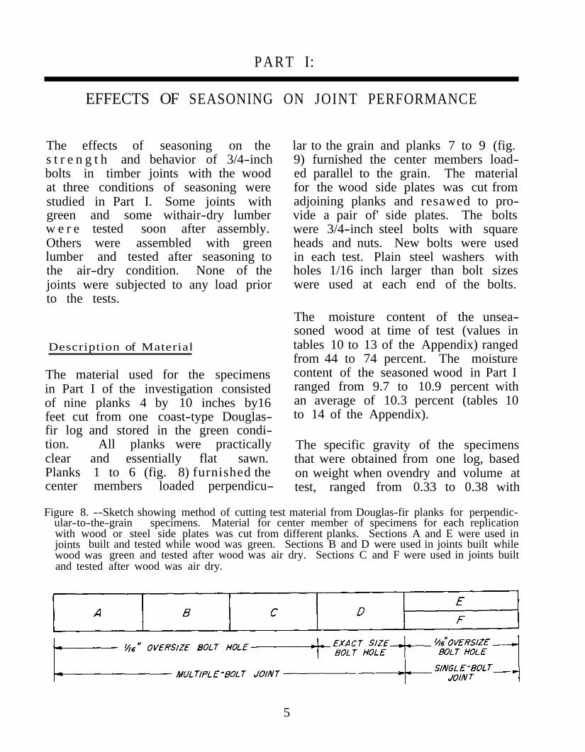
The material used for the specimens in Part I of the investigation consisted of nine planks 4 by 10 inches by16 feet cut from one coast-type Douglas-fir log and stored in the green condition. All planks were practically clear and essentially flat sawn. Planks 1 to 6 (fig. 8) furnished the center members loaded perpendicu
lar to the grain and planks 7 to 9 (fig. 9) furnished the center members loaded parallel to the grain. The material for the wood side plates was cut from adjoining planks and resawed to provide a pair of' side plates. The bolts were 3/4-inch steel bolts with square heads and nuts. New bolts were used in each test. Plain steel washers with holes 1/16 inch larger than bolt sizes were used at each end of the bolts.
The moisture content of the unseasoned wood at time of test (values in tables 10 to 13 of the Appendix) ranged from 44 to 74 percent. The moisture content of the seasoned wood in Part I ranged from 9.7 to 10.9 percent with an average of 10.3 percent (tables 10 to 14 of the Appendix).
The specific gravity of the specimens that were obtained from one log, based on weight when ovendry and volume at test, ranged from 0.33 to 0.38 with
Figure 8. --Sketch showing method of cutting test material from Douglas-fir planks for perpendicular-to-the-grain specimens. Material for center member of specimens for each replicationwith wood or steel side plates was cut from different planks. Sections A and E were used in joints built and tested while wood was green. Sections B and D were used in joints built while wood was green and tested after wood was air dry. Sections C and F were used in joints built and tested after wood was air dry.
5
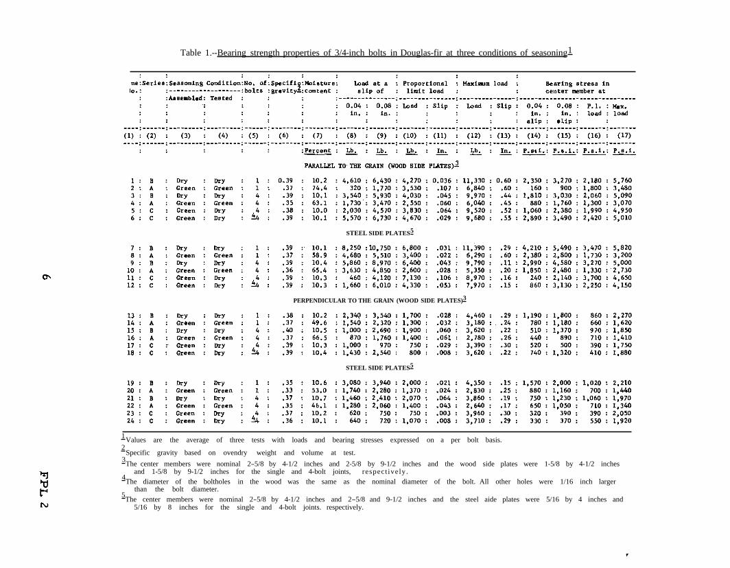
Table 1.--Bearing strength properties of 3/4-inch bolts in Douglas-fir at three conditions of seasoning1
STEEL SIDE PLATES5
PERPENDICULAR TO THE GRAIN (WOOD SIDE PLATES)3
STEEL SIDE PLATES5
1 Values are the average of three tests with loads and bearing stresses expressed on a per bolt basis. 2
Specific gravity based on ovendry weight and volume at test. 3The center members were nominal 2-5/8 by 4-1/2 inches and 2-5/8 by 9-1/2 inches and the wood side plates were 1-5/8 by 4-1/2 inches
and 1-5/8 by 9-1/2 inches for the single and 4-bolt joints, respect ively.4The diameter of the boltholes in the wood was the same as the nominal diameter of the bolt. All other holes were 1/16 inch larger
than the bolt diameter. 5The center members were nominal 2-5/8 by 4-1/2 inches and 2-5/8 and 9-1/2 inches and the steel aide plates were 5/16 by 4 inches and
5/16 by 8 inches for the single and 4-bolt joints. respectively.

Figure 9.--Sketch showing method of cutting test material from Douglas-fir planks for parallelto-the-grab specimens. Sections A, E, I, and J were used in joints built and tested while wood was green. Sections B, D, F, and H were used in joints built while wood was green but air dried before test. Sections C, G, K, and L were used in joints built after wood was air seasoned.
an average of 0.36 for the green material, and from 0.35 to 0.42 with an average of 0.38 for the dry material (values given in tables 10 to 14 of the Appendix). T h e average specific gravities of the material used in the tests of both Part I and Part II of the investigation are somewhat lower than the average specific gravity of the species, which is 0.48 for material at 12 percent moisture content. 4, 5
The specimens were grouped into series A, B, and C corresponding to three differentmoisture or seasoning conditions. The specimens in series A were constructed of green material and were tested without seasoning. In series B, the green material was cut to the approximate size of the specimens and the pieces stored in an unheated building for about 1 year. The specimens were then constructed from the seasoned pieces and tested.
In series C, the specimens were fabricated and assembled of green material, stored along with the material of series B for 1 year, and tested.
Presentation of Data
The experimental data for series A, B, and C of Part I of the investigation are summarized and compared in table 1 and in figures 10 to 15. Results obtained for joints in series B of Part I with 3/4-inch bolts in material assembled dry and tested dry are also incorporated, f o r comparative purposes, in tables 6 and 9, of Part II. The data listed in tables 1, 6, and 9 and plotted in the figures are average values per bolt obtained from tests of three specimens of a kind. Loads for four-bolt joints were divided by four to obtain comparative values per bolt. Tables 2 to 5 and tables 10 to 14 of Appendix A also present effects of the three conditions of seasoning and other variables on the strength of 3member bolted joints.
Figures 10 to 15 present composite load-slip curves (average values of loads at chosen slip values) from tests of three joints of a kind for 3/4-inch bolts in lumber in three conditions of seasoning. The loads plotted in the
5Markwardt, L. J., and Wilson, T. R. C. Strength and related properties of woods grown in the United States. U.S. Dept. Agr.Tech. Bull. 479. 99 pp., illus. Sept. 1935. 7
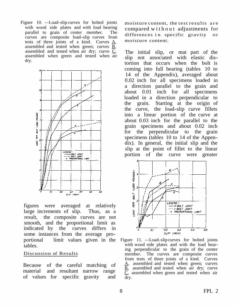
Figure 10. --Load-slip curves for bolted joints with wood side plates and with load bearing parallel to grain of center member. The curves are composite load-slip curves from tests of three joints of a kind. Curves A, assembled and tested when green; curves B, assembled and tested when air dry; curve C, assembled when green and tested when air dry.
figures were averaged at relatively large increments of slip. Thus, as a result, the composite curves are not smooth, and the proportional limit as indicated by the curves differs in some instances from the average proportional limit values given in the tables. Discussion of Results
Because of the careful matching of material and resultant narrow range of values for specific gravity and
moisture content, the tes t resul ts a r e compared w i t h o u t adjustments for differences i n specific gravity o r moisture content.
The initial slip, or mat part of the slip not associated with elastic distortion that occurs when the bolt is coming into full bearing (tables 10 to 14 of the Appendix), averaged about 0.02 inch for all specimens loaded in a direction parallel to the grain and about 0.01 inch for all specimens loaded in a direction perpendicular to the grain. Starting at the origin of the curve, the load-slip curve fillets into a linear portion of the curve at about 0.03 inch for the parallel to the grain specimens and about 0.02 inch for the perpendicular to the grain specimens (tables 10 to 14 of the Appendix). In general, the initial slip and the slip at the point of fillet to the linear portion of the curve were greater
Figure 11. --Load-slip curves for bolted joints with wood side plates and with the load bearing perpendicular to the grain of the center member. The curves are composite curves from tests of three joints of a kind. Curves A, assembled and tested when green; curves B, assembled and tested when air dry; curve C, assembled when green and tested when air dry.
8 FPL 2
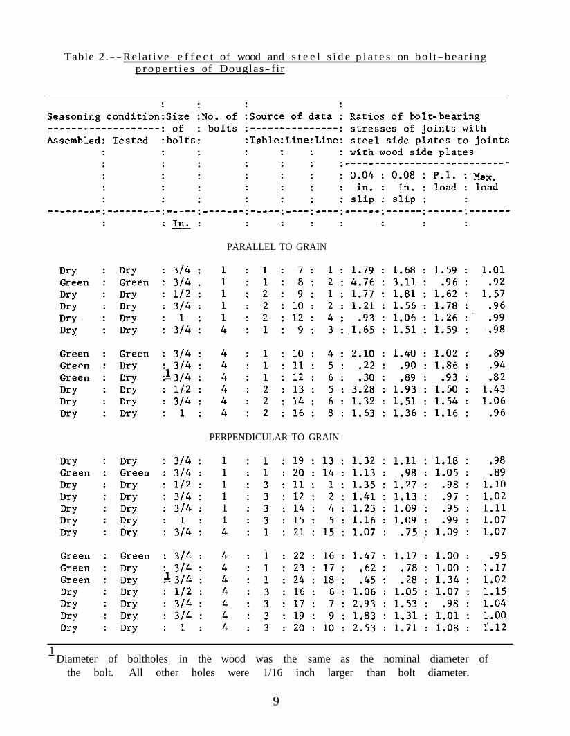
--Table 2. Relat ive e f f e c t of wood and s t e e l s i d e p l a t e s on bol t- bear ing p r o p e r t i e s of Douglas- fir
PARALLEL TO GRAIN
PERPENDICULAR TO GRAIN
1 Diameter of boltholes in the wood was the same as the nominal diameter of
the bolt. All other holes were 1/16 inch larger than bolt diameter.
9

for the four-bolt joints than for the single-bolt joints. The joints with bolts bearing parallel to the grain that were constructed green and permitted to season before test showed greater nonelastic slip than the one- and four-bolt joints of drylumber and the four-b o l t joints of g r e e n lumber. The joints with one bolt in green lumber
Figure 12. --Load- sl ipcurves for bolted joints with steel side plates and with the load bearing parallel to the grain of the center member. The curves are composite curves from tests of three joints of a kind. Curves A, assembled and tested when green; curves B, assembled and tested when air dry; curve C, assembled when green and tested when air dry.
showed greater initial slip than all other joints. The joints with bolts in snug-fitting holes showed less initial joint slip than the corresponding joints with bolts in oversize holes, particularly when wood side plates were used. The joints with the bolts bearing perpendicular to the grain in snug-fitting and oversize holes that were constructed of green material and permitted to season before test did not exhibit any initial nonelastic slip. Presumably, the shrinkage of the members brought the bolts into firm bearing with the wood.
Joints with Bolts Bearing Paral le l to the Grain
Joints with wood and steel side plates . --In joints constructed of green lumber, the joints with steel sideplates had bearing stresses at 0.04-inch and 0.08-inch slip that were from 40 percent to nearly 5 times greater than the stresses with wood side plates, but the proportional limit stresses were about the same for the two typesof side plates (table 2).
Thebearing stresses obtained for the joints that were assembled green and subjected to a period of seasoning were somewhat erratic but, in general, the joints with steel plates gave considerably lower values than similar joints with wood side plates, except for one value at proportional limit (table 2).
Joints with one and four bolts. --For four-bolt joints in green lumber, the proportionallimit load with wood side plates was 72 percent and, with steel side plates, 76 percent that of the joints with one bolt (table 5).
10 FPL 2

Table 3.--Relative effect of hole size on the bolt-bearing properties of Douglas-fir
PARALLEL TO GRAIN
PERPENDICULAR TO GRAIN
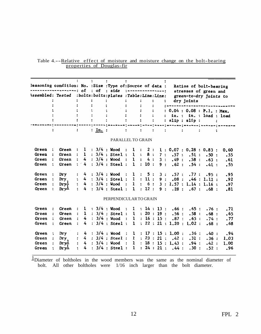
Table 4.--Relative ef fec t of moisture and moisture change on the bolt-bearing properties of Douglas-fir
PARALLEL TO GRAIN
PERPENDICULAR TO GRAIN
1Diameter of boltholes in the wood members was the same as the nominal diameter of bolt. All other boltholes were 1/16 inch larger than the bolt diameter.
12 FPL 2
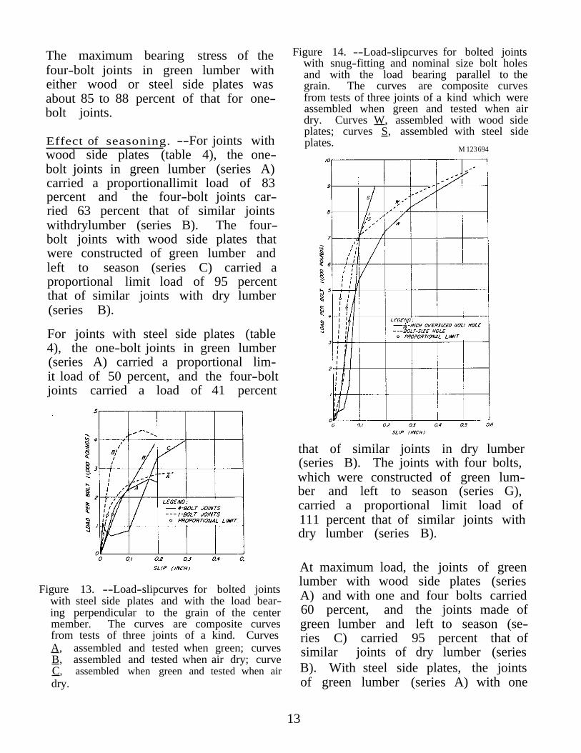
The maximum bearing stress of the four-bolt joints in green lumber with either wood or steel side plates was about 85 to 88 percent of that for one-bolt joints.
Effect of seasoning. --For joints with wood side plates (table 4), the one-bolt joints in green lumber (series A) carried a proportionallimit load of 83 percent and the four-bolt joints carried 63 percent that of similar joints withdrylumber (series B). The four-bolt joints with wood side plates that were constructed of green lumber and left to season (series C) carried a proportional limit load of 95 percent that of similar joints with dry lumber (series B).
For joints with steel side plates (table 4), the one-bolt joints in green lumber (series A) carried a proportional limit load of 50 percent, and the four-bolt joints carried a load of 41 percent
Figure 13. --Load-slipcurves for bolted joints with steel side plates and with the load bearing perpendicular to the grain of the center member. The curves are composite curves from tests of three joints of a kind. Curves A, assembled and tested when green; curves B, assembled and tested when air dry; curve C, assembled when green and tested when air dry.
Figure 14. --Load-slipcurves for bolted jointswith snug-fitting and nominal size bolt holes and with the load bearing parallel to the grain. The curves are composite curves from tests of three joints of a kind which were assembled when green and tested when air dry. Curves W, assembled with wood side plates; curves S, assembled with steel side plates.
M 123 694
that of similar joints in dry lumber (series B). The joints with four bolts, which were constructed of green lumber and left to season (series G), carried a proportional limit load of 111 percent that of similar joints with dry lumber (series B).
At maximum load, the joints of green lumber with wood side plates (series A) and with one and four bolts carried 60 percent, and the joints made of green lumber and left to season (series C) carried 95 percent that of similar joints of dry lumber (series B). With steel side plates, the joints of green lumber (series A) with one
13
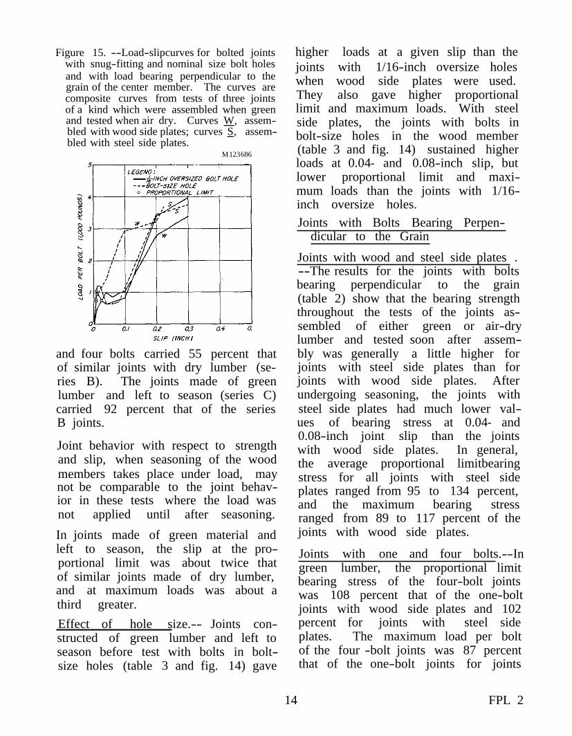
Figure 15. --Load-slipcurves for bolted joints with snug-fitting and nominal size bolt holes and with load bearing perpendicular to the grain of the center member. The curves are composite curves from tests of three joints of a kind which were assembled when greenand tested when air dry. Curves W, assembled with wood side plates; curves S, assembled with steel side plates.
M 123686
and four bolts carried 55 percent that of similar joints with dry lumber (series B). The joints made of green lumber and left to season (series C) carried 92 percent that of the series B joints.
Joint behavior with respect to strength and slip, when seasoning of the wood members takes place under load, may not be comparable to the joint behavior in these tests where the load was not applied until after seasoning.
In joints made of green material and left to season, the slip at the proportional limit was about twice that of similar joints made of dry lumber, and at maximum loads was about a third greater. Effect of hole size.-- Joints constructed of green lumber and left to season before test with bolts in bolt-size holes (table 3 and fig. 14) gave
higher loads at a given slip than the joints with 1/16-inch oversize holes when wood side plates were used. They also gave higher proportional limit and maximum loads. With steel side plates, the joints with bolts in bolt-size holes in the wood member (table 3 and fig. 14) sustained higher loads at 0.04- and 0.08-inch slip, but lower proportional limit and maximum loads than the joints with 1/16inch oversize holes. Joints with Bolts Bearing Perpen
dicular to the Grain
Joints with wood and steel side plates . --The results for the joints with bolts bearing perpendicular to the grain (table 2) show that the bearing strength throughout the tests of the joints assembled of either green or air-dry lumber and tested soon after assembly was generally a little higher for joints with steel side plates than for joints with wood side plates. After undergoing seasoning, the joints with steel side plates had much lower values of bearing stress at 0.04- and 0.08-inch joint slip than the joints with wood side plates. In general, the average proportional limitbearing stress for all joints with steel side plates ranged from 95 to 134 percent, and the maximum bearing stress ranged from 89 to 117 percent of the joints with wood side plates.
Joints with one and four bolts.--In green lumber, the proportional limit bearing stress of the four-bolt joints was 108 percent that of the one-bolt joints with wood side plates and 102 percent for joints with steel side plates. The maximum load per bolt of the four -bolt joints was 87 percent that of the one-bolt joints for joints
14 FPL 2

Table 5.--Relative effect of one bolt and four-bolts per joint on the bolt-bearing properties of Douglas-fir
PARALLEL TO GRAIN
PERPENDICULAR TO GRAIN
1 All boltholes were 1/16 inch larger than bolt diameter.
15
with wood side plates and 93 percent that for joints with steel side plates.
Effect of seasoning. --For joints with wood side plates (table 4), the one-bolt joints of green lumber (series A) carried a proportional limit load of 76 percent that of similar joints of air-drylumber (series B). The four-bolt joints of green lumber carried a proportional limit load of 74 percent that of the four-bolt joints of air-dry lumber. The four-bolt joints constructed of green lumber and left to season (series C) carried a proportional limit load of 40 percent that of joints of air-dry lumber.
For joints with steel side plates (table 4), the one- and four-bolt joints of green lumber carried a proportional limit load of 68 percent that of similar joints of air-dry lumber, and the four-bolt joints constructed of green lumber and left to season carried 36 percent that of similar joints of airdrylumber.
At maximum load, the one-bolt joints with wood side plates and constructed of green lumber carried 71 percent, and the four-bolt joints carried 77 percent that of similar joints of air-dry lumber. The joints constructed of green lumber and left to season carried 94 percent that of similar joints of air-dry lumber. With steel side plates, the one- and four-bolt
joints of green lumber carried a maximum load of about 67 percent. The joints constructed of green lumber and left to season carried 103 per
cent that of similar joints of air-dry lumber.
Effect of hole size. --The joints constructed of green lumber and left to season with bolts in bolt-size holes gave higher loads for a given slip, as well as somewhat higher proportional limit and maximum loads (table 3), than the joints with 1/16-inch oversize holes when wood side plates were used. Similar joints with steel side plates gave proportional limit loads that were higher and maximum loads that were slightly lower than the joints with 1/16-inch oversize holes. In general, the joints with bolt-size holes showed less joint slip for a given load throughout the tests than the joints with oversize holes (fig. 15).
Joint Failures
The failures that resulted in the joints are classified as bending of the bolts, crushingunder the bolt, and splitting ofthewood (tables 10 to 14 of the Appendix).
In general, the bolts bearing parallel to the grain showed crushing of the wood beneath the bolts. They also showed splitting of the wood through the boltholes of all joints except the single-bolt joints with wood side plates. Some bolts were bent, particularly in the joints with wood side plates.
All joints bearing perpendicular to the grain showed crushing under the bolts and splitting of the wood. Some bolts were bent.
16 FPL 2

PART II.
EFFECTS OF BOLT DIAMETER ON JOINT PERFORMANCE
The effects of bolt diameter in the strength and behavior of 1/2-, 3/4-, and 1-inch bolts in timber joints were studied in Part II. The joints were constructed o f air -dry Douglas -fir and were tested soon after assembly. The results include some of the data for 3/4-inch bolts in air-dry material from Part I.
Description of Material
The material used for the specimens in Part II of the investigation consisted of nine planks 3 by 10 inches by 18 feet and six planks 2 by 12 inches by 20 feet of S4S Construction grade lumber of dry Coast-type Douglas-fir. T h e nominal 3-inchthickplanks were numbered 10 to 18. Planks numbered 10 to 12 (fig. 16) were used for the center members of the specimens with loads applied parallel to the grain, and planks 13 to 18 (figs. 17 and 18) were used for the
center members of the specimens with loads applied perpendicular to the grain. The planks used for the specimens l o a d e d perpendicular to the grain were not long enough to provide matched specimens for three sizes of bolts. Thus specimens with 3/4- and 1-inch bolts were matched in planks 13 to 15 (fig. 17) and specimens with the 1/2-inch bolts were matched with duplicate specimens with 3/4-inch bolts in planks 16 to 18 (fig. 18). The wood side plates used in conjunction with the center members were cut from the 2- by 12-inch planks. The individual center and side members of all specimens were positioned along the planks so that the areas occupied by the bolts were reasonably free of knots. The planks, in general, showed a moderate amount of seasoning degrade in the form of checking, twisting, and cupping. They were not resurfaced prior to t h e fabrication o f t h e specimens.
M 123682
Figure 16.--Sketch showing method of cutting test material from Douglas-fir planks (Nos. 10, 11, and 12) for parallel-to-the-grain specimens in Part II of the investigation.
17
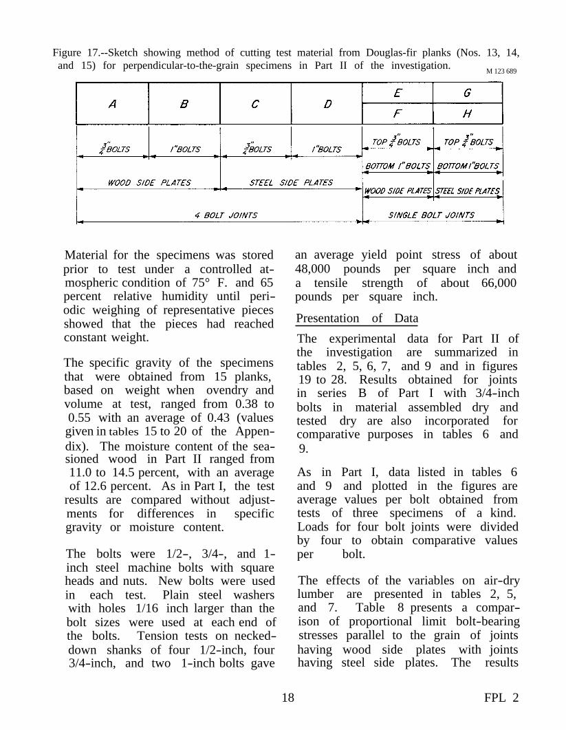
Figure 17.--Sketch showing method of cutting test material from Douglas-fir planks (Nos. 13, 14, and 15) for perpendicular-to-the-grain specimens in Part II of the investigation.
M 123 689
Material for the specimens was stored prior to test under a controlled atmospheric condition of 75° F. and 65 percent relative humidity until periodic weighing of representative pieces showed that the pieces had reached constant weight.
The specific gravity of the specimens that were obtained from 15 planks, based on weight when ovendry and volume at test, ranged from 0.38 to 0.55 with an average of 0.43 (values given in tables 15 to 20 of the Appendix). The moisture content of the seasioned wood in Part II ranged from 11.0 to 14.5 percent, with an average of 12.6 percent. As in Part I, the test
results are compared without adjustments for differences in specific gravity or moisture content.
The bolts were 1/2-, 3/4-, and 1inch steel machine bolts with square heads and nuts. New bolts were used in each test. Plain steel washers with holes 1/16 inch larger than the bolt sizes were used at each end of the bolts. Tension tests on necked-down shanks of four 1/2-inch, four 3/4-inch, and two 1-inch bolts gave
an average yield point stress of about 48,000 pounds per square inch and a tensile strength of about 66,000 pounds per square inch.
Presentation of Data
The experimental data for Part II of the investigation are summarized in tables 2, 5, 6, 7, and 9 and in figures 19 to 28. Results obtained for joints in series B of Part I with 3/4-inch bolts in material assembled dry and tested dry are also incorporated for comparative purposes in tables 6 and 9.
As in Part I, data listed in tables 6 and 9 and plotted in the figures are average values per bolt obtained from tests of three specimens of a kind. Loads for four bolt joints were divided by four to obtain comparative values per bolt.
The effects of the variables on air-dry lumber are presented in tables 2, 5, and 7. Table 8 presents a comparison of proportional limit bolt-bearing stresses parallel to the grain of joints having wood side plates with jointshaving steel side plates. The results
18 FPL 2
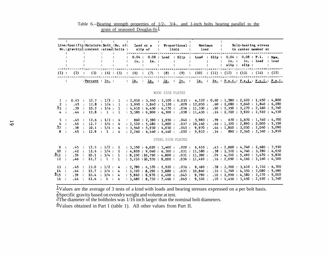
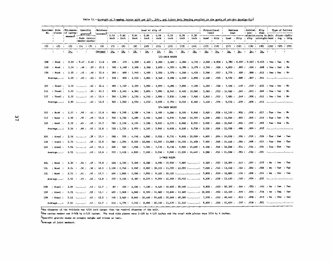
Table 6.--Bearing strength properties of 1/2-. 3/4-. and 1-inch bolts bearing parallel to the grain of seasoned Douglas-fir1
WOOD SIDE PLATES
STEEL SIDE PLATES
1Values are the average of 3 tests of a kind with loads and bearing stresses expressed on a per bolt basis. 2Specific gravity based on ovendry weight and volume at test.3The diameter of the boltholes was 1/16 inch larger than the nominal bolt diameters. 4Values obtained in Part I (table 1). All other values from Part II.
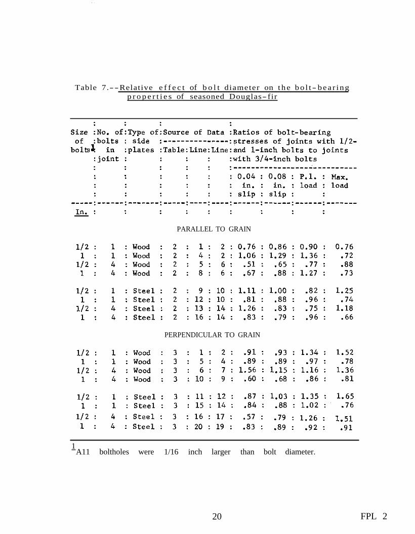
--Table 7. Relative e f f e c t of b o l t diameter on t h e bo l t - bea r ing p r o p e r t i e s of seasoned Douglas- fir
PARALLEL TO GRAIN
PERPENDICULAR TO GRAIN
1A11 boltholes were 1/16 inch larger than bolt diameter.
20 FPL 2

Figure 18. --Sketch showing method of cutting test material from Douglas-fir planks (NOS. 16, 17, and 18) for perpendicular-to-the-grain specimens in Part II of the investigation.
M 123 688
of individual tests are presented in between the bolt-bearing stress at tables 15 to 20 of the Appendix. the proportional limit and L/d for
parallel and perpendicular to the grain Figures 19 to 22 present load-slip loading of one- and four-bolt joints curves for 1/2-, 3/4-, and 1-inch in air-dry Douglas -fir. bolts in dry Douglas-fir. The loads plotted in the figures were averaged Figure 28 presents the relationship at relatively large increments of slip of the ratio of the bolt-bearing stress and, as in the preceding figures, the perpendicular to the grain at the pro-curves are not smooth and the pro- portional limit to the average proportional limit differs in some in- portional limit stress perpendicular stances from the average proportional to the grain of air-dry Douglas-fir limit values given in the tables. and the bolt diameter. A comparison
of these data and the data taken from2Figures 23 to 25 present in chart form figure 13 of Technical Bulletin 332
a comparison of the bolt -bearing for maple and spruce is also prestress for the various bolted joints sented in the figure.in air-dry Douglas-fir at 0.04- and 0.08-inch slip, proportional limit Discussion of Resultsand maximum load.
Figure 26 presents a relationship be- Similarly, as in Part I, the initial 'tweentwo ratios: (1) the length of the slip, orthatpart of the slip not assobolt bearing in the center member to ciated with elastic distortion that octhe diameter of the bolt (L/d) and (2) curs when the bolt is coming into full the bolt-bearing stress parallel to the bearing (tables 15 to 20 of the Appengrain at the proportional limit to the dix), averaged about 0.02 inch for all average crushing strength parallel to specimens loaded in a direction par-the grain of air-dry Douglas-fir. allel to the grain and about 0.01 inch
for all specimens loaded in a di-Figure 27 presents the relationship rection perpendicular to the grain.
21

Starting at the origin of the curve, with wood side plates (table 2). At the load-slip curve fillets into a lin- the proportional limit, they had bolt-ear portion of the curve at about 0.03 bearing stresses 16 to 78 percentinch for the parallel to the grain spec- greater.imens and about 0.02 inch for the perpendicular to the grain specimens Atmaximumload, the bearing stress (tables 15 to 20 of the Appendix). In per bolt for the joints with wood side general, the initial slip and the slip plates was in general comparable to at the point of fillet to the linear por- that of the joints with steel side plates tion of the curve were greater for the except for the joints with 1/2-inch four-bolt joints than for the single- bolts in which the joints with steel bolt joints. side plates gave a bearing stress of
143 to 157 percent that of the joints with wood side plates (table 2).
Joints with Bolts Bearing Parallel to the Grain A comparison of joints with bolts
bearing parallel to the grain in air-Joints with wood and steel side plates. dry lumber with wood side plates and --In joints constructed of air-dry similar joints with steel side plates lumber, t h e joints with s t e e l side is also given in column 7 of table 8 plates for the most part had bolt- for both one-bolt and four-bolt joints bearing stresses at 0.04-inch slip and with 1/2-, 3/4-, and 1-inch-diameter 0.08-inch slip from 7 percent less bolts. The average bearing stress to over 3 times greater than joints values at the proportional limit for
M 123 687 Figure 19. --Load-slipcurves for bolted joints with wood side plates and with load bearing parallel to the grain of air-dry Douglas-fir members. The curves are composite load-slip curves from tests of three joints of a kind.
22 FPL 2
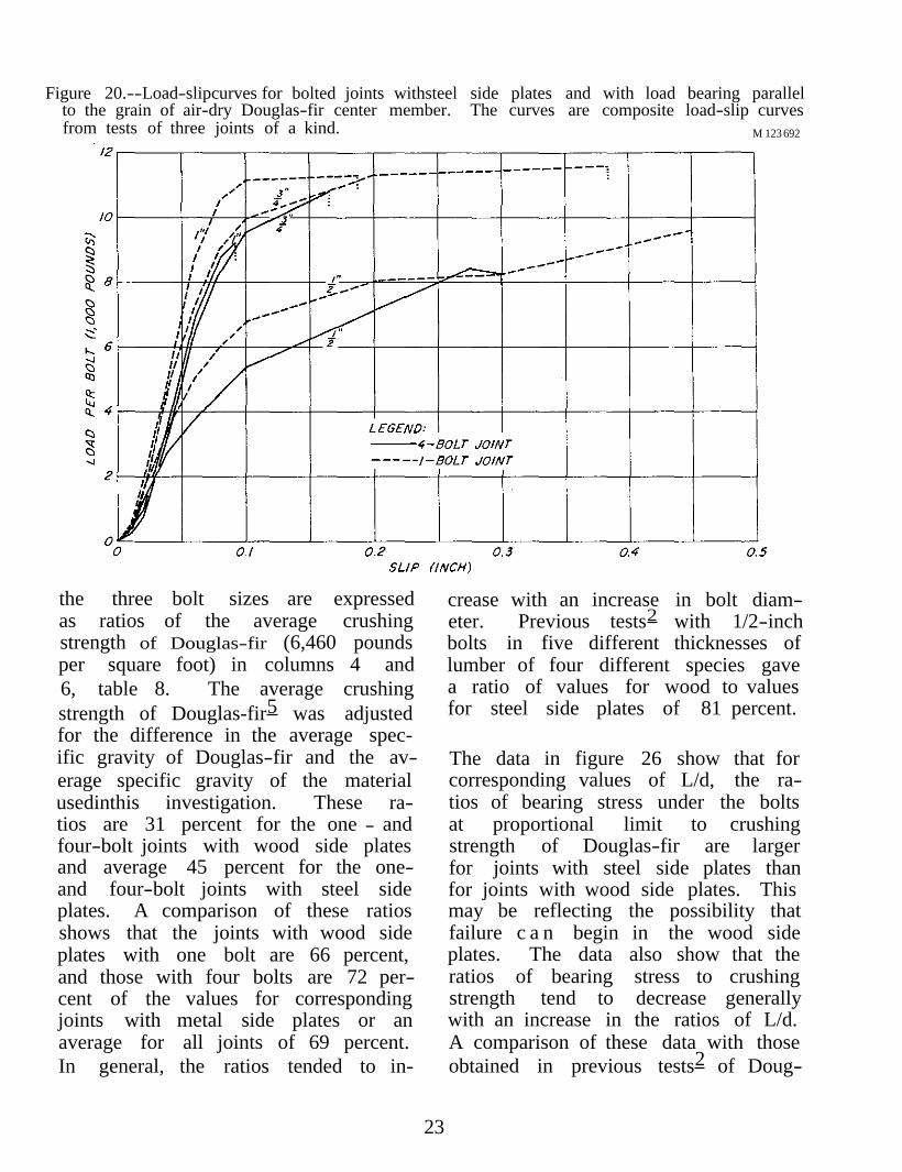
Figure 20.--Load-slipcurves for bolted joints withsteel side plates and with load bearing parallel to the grain of air-dry Douglas-fir center member. The curves are composite load-slip curves from tests of three joints of a kind. M 123 692
the three bolt sizes are expressed as ratios of the average crushing strength of Douglas-fir (6,460 pounds per square foot) in columns 4 and 6, table 8. The average crushing strength of Douglas-fir5 was adjusted for the difference in the average specific gravity of Douglas-fir and the average specific gravity of the material usedinthis investigation. These ratios are 31 percent for the one - and four-bolt joints with wood side plates and average 45 percent for the one-and four-bolt joints with steel side plates. A comparison of these ratios shows that the joints with wood side plates with one bolt are 66 percent, and those with four bolts are 72 percent of the values for corresponding joints with metal side plates or an average for all joints of 69 percent. In general, the ratios tended to in
crease with an increase in bolt diameter. Previous tests2 with 1/2-inch bolts in five different thicknesses of lumber of four different species gave a ratio of values for wood to values for steel side plates of 81 percent.
The data in figure 26 show that for corresponding values of L/d, the ratios of bearing stress under the bolts at proportional limit to crushing strength of Douglas-fir are larger for joints with steel side plates than for joints with wood side plates. This may be reflecting the possibility that failure c a n begin in the wood side plates. The data also show that the ratios of bearing stress to crushing strength tend to decrease generally with an increase in the ratios of L/d. A comparison of these data with those obtained in previous tests2 of Doug
23

las-fir joints with steel side plates shows good correlation in the L/d range of 4 to 5 but rather poor correlation at the smaller ratios of L/d. The data in figure 27 also show that the joints with steel side plates gave higher bearing stresses than the joints with wood side plates for bearing parallel to grain, but not for bearing perpendicular to grain.
Joints with one and four bolts.--In air-dry lumber, the bearing stress per bolt at the proportional limit for the four-bolt joints w a s a b o u t the same as that of the one-bolt joints when wood side plates were used and about 92 percent that of the one-bolt joints when steel side plates were used (table 5). The maximum bearing stress of the four-bolt joints in dry lumber with either wood or steel side plates was about 89 percent of that of the one-bolt joints (table 5).
Effect of bolt size. --The results show (table 7 and figs. 19 and 20) that while considerable variation in bearing strength exists among the bolt sizes and types of side plates, the 3/4-inch bolts for the most part gave higher bearing strength than the 1/2- and 1inch bolts except for the 1/2-inchbolts with steel side plates. The average bearing strength at the proportional limit for all joints with 1/2-inch bolts was from 75 to 90 percent. All joints with 1-inch bolts had a bearing strength at the proportional limit of from 96 to 136 percent that of the joints with 3/4inch bolts. At maximum load, the average bearing stress for the joints with 1/2-inch bolts was 76 to 125 percent, and with the 1-inch bolts was 66 to 74 percent that of the joints with 3/4-inch bolts.
Joints with Bolts Bearing Perpendicular to the Grain
M 123 685
Figure 21. --Load-slipcurves for bolted joints with wood side plates and with load bearing perpendicular to the grain of the air-dry Douglas-fir center member. The curves are composite curves from tests of three joints of a kind. The curves for the 3/4-inch bolts with the subscript "a" are for joints whose material is matched to that of the joints with 1/2-inch bolts, and the curves for the 3/4-inch bolts with the subscript "b" are for joints whose material is matched to that of the joints with 1-inch bolts.
24 FPL 2

Table 8.--Comparative p ropor t iona l l i m i t bear ing s t r e n g t h p a r a l l e l t o t he g r a in i n seasoned Douglas- fir of bol ted j o i n t s wi th wood s i d e p l a t e s and those wi th metal p l a t e s
1Bearing values from table 2. 2Average crushing strength of Douglas-fir at 12 percent moisture content is given as
7,420 pounds per square inch in Tech. Bull. No. 479, "Strength and Related Propertiesof Woods Grown in the United States." This value was adjusted for the specific
gravity difference of the material

Joints with wood and steel side plates. that for both types of side plates, the --As in Part I, the results for the bearing stress generally increased
with an increase in L/d.joints with bolts bearing perpendicular to the grain (table 4) show that the bearing strength throughout the tests of the joints assembled of air-dry lumber and tested soon after assembly was generally a little higher for joints with steel side plates than for joints with wood side plates. In general, the average proportional limit bearing stress for all joints with steel side plates ranged from 95 to 118 percent and the maximum bearing stress ranged from 98 to 115 percent that of the joints with wood side plates.
The data in figure 27 show that the joints with steel side plates gave only a slightly higher bearing stress than the joints with wood side plates and
Joints with one and four bolts.--In dry lumber (table 5), the bearing stress per bolt at the proportional limit of the four-bolt joints with 1/2-, 3/4-, and 1-inch bolts ranged from 80 to 112 percent that of the one-bolt joints when wood side plates were used and from 87 to 108 percent when steel side plates were used.
At maximum load, the bearing stress per bolt in dry lumber (table 5) of the four-bolt joints ranged from 72 to 81 percent that of the one-bolt joints when wood side plates were used and from 63 to 89 percent when steel side plates were used.
M 123 691
Figure 22. --Load-slipcurves for bolted joints with steel side plates and with load bearing perpendicular to the grainofthe air-dry Douglas-fir center member. The curves are composite curves from tests of three joints of a kind. The curves for the 3/4-inch bolts with the subscript "a" are for joints whose material is matched to that of the joints with 1/2-inch bolts, and the curves for the 3/4-inch bolts with the subscript "b" are for joints whose material is matched to that of the joints with 1-inch bolts.
26 FPL 2

Effect of bolt size. --The bearing stress at the proportional limit for all joints with 1/2-inch bolts in both wood and steel side plates ranged from 116 to 135 percent, and for all joints with 1-inch bolts from 86 to 102 percent that of similar joints with 3/4-inch bolts (table 7). At maximum load, the bearing stress for the joints with 1/2-inch bolts ranged from 136 to 165 percent, and with 1-inch bolts, ranged from 76 to 91 percent that of the joints with 3/4-inch bolts.
The relationship of the ratio of the proportional limit bearing stress perpendicular to the grain and the pro
portional limit compressive stress perpendicular to the grain of Douglas-fir (690 pounds per square inch) with bolt diameter is presented in figure 28 for one- and four-bolt joints. The average proportional limit compressive stress perpendicular to the grain of Douglas-fir4 was adjusted for the difference in the average specific gravity of the species and the average specific gravity of the material used in Part II. The results show that most of the ratios obtained in these tests are greater than those obtained in the previous tests with maple and spruce; however, the trend of the data is similar.2 M 123 690
Figure 23. --Chart showing the bearing stress parallel to the grain at 0.04 inch, 0.08 inch, proportional limit, and maximum load for one- and four-bolt joints with 1/2-, 3/4-, and 1-inch bolts bearing in nominal 3-inch air-dry Douglas -fir with wood and steel side plates.
27

1 2 3 4 5 6
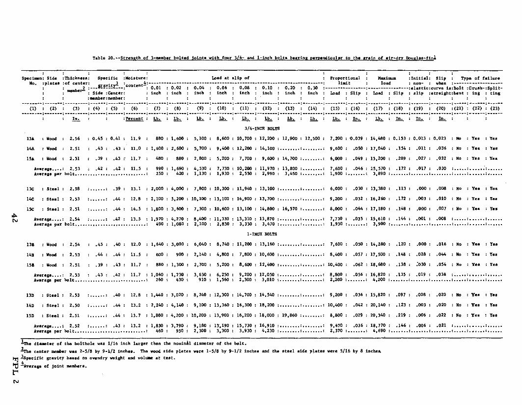
Table 9.--Bearing strength properties of 1/2-, 3/4-, and 1-inch bolts bearing perpendicular to the grain of seasoned Douglas-fir 1
Values are the average of 3 tests of a kind with loads and bearing stresses expressed on a per bolt basis. Specific gravity based on ovendry weight and volume at test. The diameter of the boltholes was 1/16 inch larger than the nominal bolt diameters. Material matched to that of specimens with 1/2-inch bolts. Values obtained from tests in Part I (table 1). All other valves from Part II. Material matched to that of specimens with 1-inch bolts.
28 FPL 2

Figure 24. --Chart showing the bearing stress perpendicular to the grain at 0.04 inch, 0.08 inch, proportional limit, and maximum load for one- and four-bolt joints with 1/2- and 3/4-inch bolts bearing in nominal 3-inch air-dry Douglas-fir with wood and steel side plates.
M 123 693
Joint Failures inch bolts and the single-bolt joints with 3/4-inch bolts with wood side
The failures that resulted in the joints plates. All 1/2-inch bolts were bent. are classified as bending of the bolts, Some 3/4-inch bolts were bent, par-crushing under the bolt, and splitting ticularly in the joints with wood side of the wood (tables 15 to 20 of the Ap- plates. None of the 1-inch bolts were pendix). bent.
In general, the bolts bearing parallel All joints bearing perpendicular to to the grain showed crushing of the the grain showed crushing under the wood beneath all sizes of bolts. They bolts and splitting of the wood. All also showed splitting of the wood 1/2-inch bolts were bent; some 3/4through the boltholes of all joints inch bolts were bent; but none of the except the single-bolt joints with 12- 1-inch bolts were bent.
29

CONCLUSIONS
The bearing strength data obtained for the three-member bolted joints in nominal 3-inch Douglas-fir with one and four bolts bearing parallel or perpendicular to the grain exhibited large variations among various groups of specimens as well as among individual specimens of a kind. The results, in general, show that for the items studied with one species and one thickness of member, the design data currently in use for bolted joints are technicallysound. In joints with four bolts bearing parallel to the grain, however, the bolt-bearing strength per bolt should be 90 percent that of
a single-bolt joint.
The following specific conclusions are based on the average proportional limitbearing stress of groups of one-and four-bolt specimens of similar construction, except that only joints with four bolts were used in specimens that were made of green material and tested after seasoning. In addition to these data, other factors such as maximum load, load at a specific joint deformation, and quality of craftsmanship should also be considered in the evaluation of joint behavior and are specifically mentioned in some of the conclusions.
M 123 679
Figure 25. --Chart showing the bearing stress perpendicular to the grain at 0.04 inch, 0.08 inch, proportional limit, and maximum load for one- and four-bolt joints with 3/4- and 1-inch bolts bearing in nominal 3-inch air-dry Douglas-fir with wood and steel side plates.
30 FPL 2

Figure 26. --Relationship between ratio of bolt bearing stress at proportional limit to crushingstrength and ratio of bearing length to bolt diameter (L/d) for joints with bolts bearing parallel to the grain of air-dry Douglas-fir. The reverse curve is taken from the data for Douglas-fir in figure 5, Tech. Bull. 332, and has been inserted for comparative purposes.
M 123 683
Bearing Paral le l to the Grain
1. T h e b o l t-bearing proportional limit stress of joints of dry material with steel side plates is about 150 percent that of joints with wood side plates, but the maximum load of the joints with steel side plates is only about 110 percent that of joints with wood side plates. 2. The bolt-bearing stress of joints of green lumber is about 60 percent that of joints of dry lumber.
3. The bolt-bearing stress of joints constructed of greenlumber and loaded after seasoning is about the same as that of joints constructed of dry lumber when all boltholes are over
size but the loads at specific slips below the proportional limit are considerably less.
4. The bolt-bearing stress of joints with 1/2-inch bolts in nominal 3-inch lumber is about 80 percent, and with 1-inch bolts it is about 115 percent that of joints with 3/4-inch bolts.
5. The bolt-bearing stress of joints with bolt-size holes constructed of green lumber and loaded after seasoning is about 120 percent that of similar joints with 1/16-inch oversize holes when wood side plates are used but only 60 percent that of joints with oversize holes when steel side plates are used.
31

Figure 27. --Relationship of the bolt-bearing stress at the proportional limit in air-dry Douglas-fir and the ratio of bearing length to bolt diameter (L/d).
M 123 684
Bearing Perpendicular to the Grain
1. The bolt-bearing stress of joints of dry material with steel side plates is about the same as that of joints with wood side plates.
2. The bolt-bearing strength per bolt of joints with four bolts is about the same as that of single-bolt joints.
3. The bolt-bearing stress of joints constructed of green lumber is about 70 percent that of joints of dry lumber.
4. The bolt-bearing stress of joints constructed of greenlumber and loaded after seasoning is about 40 percent that of joints constructed of dry lumber.
5. The bolt-bearing stress of joints with 1/2-inch bolts in nominal 3-inch lumber is about 130 percent and with 1-inch bolts it is about 95 percent that of joints with 3/4-inch bolts.
6. The bolt-bearing stress of joints with bolts in bolt-size holes is slightly higher than joints with bolts in 1/16inch oversize holes.
M 123 685
Figure 28.--Relationship between ratio of the perpendicular to the grain bolt-bearing stress at the proportional limit of air-dry Douglas-fir to the average proportional limit stress perpendicular to the grain of air-dry Douglas-fir and bolt diameter. The dashed curve is taken from figure 13, Tech. Bull. 332, and has been inserted for comparative purposes.
32 FPL 2
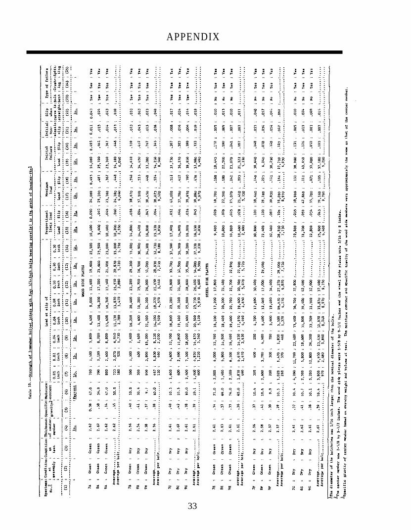
APPENDIX
33

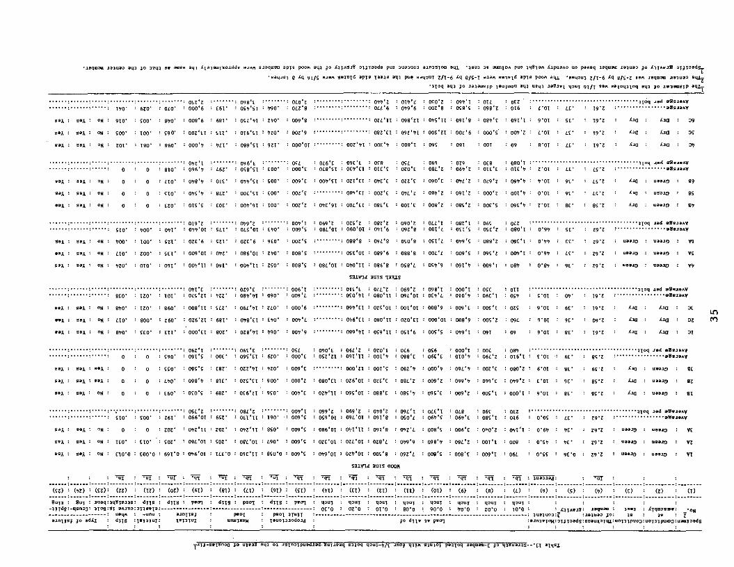
Table 11.--Strength of 3-member bolted joints with one 3/4-inch bolt bearing parallel to grain of Douglas-fir1
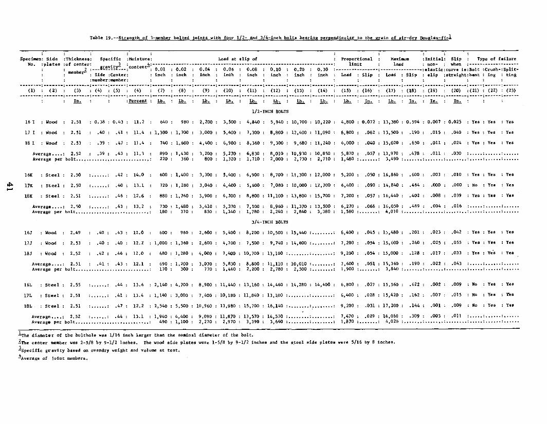
Table 12.--Strength of 3-member bolted joints with one 3/4-inch bolt bearing perpendicular to the grain of Douglas-fir 1
34 FPL 2