PERFORMANCE OF A DYNAMIC VIBRATION ABSORBER USING A ...
11
International Review of Mechanical Engineering (I.RE.M.E.), Vol. xx, n. x Manuscript received July 2012, revised July 2012 Copyright © 2012 Praise Worthy Prize S.r.l. - All rights reserved PERFORMANCE OF A DYNAMIC VIBRATION ABSORBER USING A MAGNETO-RHEOLOGICAL DAMPER Mahmoud H.Salem 1 , M.N.Anany 2 , M.El-Habrouk 3 , Sohair F. Rezeka 4 Abstract – A dynamic vibration absorbers are essentially used to protect equipment from steady- state harmonic disturbances. This paper studies the performance of a dynamic vibration absorber using a magneto-rheological (MR) damper. A mathematical model for a two-degree of freedom system is developed and simulated for different values of the current input of the MR damper. A Bouc-Wen model for hysteresis of MR damper is implemented. The responses of the primary mass of the dynamic absorber system subjected to external sinusoidal inputs are evaluated. Experiments were conducted for different values of absorber masses and input currents and the amplitude of vibration of the primary mass is recorded at different frequencies. Linear Quadratic Regulator (LQR) is used to control the force produced by the MR damper in order to minimize the main mass vertical displacement. The controlled force acquired for the MR damper is transformed to equivalent current to be applied to the current driver of the damper. The performance of LQR control is compared to that of the optimum-tuned-passive vibration absorber system using viscous dampers. The simulation results show that integrating controlled MR dampers in vibration absorber system is feasible and effective for heavy vibrating systems. LQR control of the MR damper is more effective than the optimum passive conventional absorber in both suppressing the vibration of the main mass and reducing the transmitted forces. Copyright © 2012 Praise Worthy Prize S.r.l. - All rights reserved. Keywords: Dynamic vibration absorber, MR damper, optimum-tuned-absorber, LQR control NOMENCLATURE A Parameter to determine the hysteresis loop in Bouc- Wen-model (dimensionless) c0b Constant that determine c0 , Ns/m c1a Constant that determine c1 ,Ns/m c1 b Constant that determine c1 , Ns/mV f Frequency of external force , Hz fd Force of Damper , N k1 Main Mass stiffness, N/m k2 Absorber Mass stiffness, N/m m Mass of Eccentricity, kg m1 Mass of Main, kg m2 Mass of Absorber, kg n Parameter that determine the hysteresis loop Bouc- Wen model (dimensionless) x0 Initial displacement of spring k1 associated with nominal damper force to accumulator, m x1, x2 Displacement of m1 and m2, m Abbreviations DVA Dynamic Vibration Absorber TMD Tuned Mass Damper LQR Linear Quadratic Regulator MR Magneto-Rheological MRDVA Magneto-Rheological Dynamic Vibration Absorber Greek Symbols Scaling value for the Bouc-Wen model, N/m a Constant that determine , N/m b Constant that determine , N/mV γ, µ Parameters that determine the hysteresis loop in Bouc-Wen model, m -2 μ' Mass Ratio (dimensionless) Constant to govern the first- order filter, s -1 I. Introduction Vibration absorbers have been widely applied to structures, machines, bridges and even in buildings and foundations during seismic hazards [1-9]. The main aim of the absorption system is to isolate the primary mass from extreme vibrations in order to minimize damage or failure of the system. To increase the life span of machines, engineers have used vibration absorber systems throughout all the aspects of design. The dynamic vibration absorber (DVA) or tuned-mass damper (TMD) is considered as a passive vibration control device. When a mass-spring system, referred to as a primary system, is subjected to a harmonic excitation at a constant frequency, its steady-state response can be
Transcript of PERFORMANCE OF A DYNAMIC VIBRATION ABSORBER USING A ...

International Review of Mechanical Engineering (I.RE.M.E.), Vol. xx, n. x
Manuscript received July 2012, revised July 2012 Copyright © 2012 Praise Worthy Prize S.r.l. - All rights reserved
PERFORMANCE OF A DYNAMIC VIBRATION ABSORBER
USING A MAGNETO-RHEOLOGICAL DAMPER
Mahmoud H.Salem1, M.N.Anany 2, M.El-Habrouk 3, Sohair F. Rezeka4
Abstract – A dynamic vibration absorbers are essentially used to protect equipment from steady-
state harmonic disturbances. This paper studies the performance of a dynamic vibration absorber
using a magneto-rheological (MR) damper. A mathematical model for a two-degree of freedom
system is developed and simulated for different values of the current input of the MR damper. A
Bouc-Wen model for hysteresis of MR damper is implemented. The responses of the primary mass of
the dynamic absorber system subjected to external sinusoidal inputs are evaluated. Experiments
were conducted for different values of absorber masses and input currents and the amplitude of
vibration of the primary mass is recorded at different frequencies. Linear Quadratic Regulator
(LQR) is used to control the force produced by the MR damper in order to minimize the main mass
vertical displacement. The controlled force acquired for the MR damper is transformed to equivalent
current to be applied to the current driver of the damper. The performance of LQR control is
compared to that of the optimum-tuned-passive vibration absorber system using viscous dampers.
The simulation results show that integrating controlled MR dampers in vibration absorber system is
feasible and effective for heavy vibrating systems. LQR control of the MR damper is more effective
than the optimum passive conventional absorber in both suppressing the vibration of the main mass
and reducing the transmitted forces.
Copyright © 2012 Praise Worthy Prize S.r.l. - All rights reserved.
Keywords: Dynamic vibration absorber, MR damper, optimum-tuned-absorber, LQR control
NOMENCLATURE
A Parameter to determine the hysteresis loop in Bouc-
Wen-model (dimensionless)
c0b Constant that determine c0 , Ns/m
c1a Constant that determine c1 ,Ns/m
c1 b Constant that determine c1 , Ns/mV
f Frequency of external force , Hz
fd Force of Damper , N
k1 Main Mass stiffness, N/m
k2 Absorber Mass stiffness, N/m
m Mass of Eccentricity, kg
m1 Mass of Main, kg
m2 Mass of Absorber, kg
n Parameter that determine the hysteresis loop Bouc-
Wen model (dimensionless)
x0 Initial displacement of spring k1 associated with
nominal damper force to accumulator, m
x1, x2 Displacement of m1 and m2, m
Abbreviations DVA Dynamic Vibration Absorber
TMD Tuned Mass Damper
LQR Linear Quadratic Regulator
MR Magneto-Rheological
MRDVA Magneto-Rheological Dynamic Vibration Absorber
Greek Symbols Scaling value for the Bouc-Wen model, N/m
a Constant that determine , N/m
b Constant that determine , N/mV
γ, µ Parameters that determine the hysteresis loop in
Bouc-Wen model, m-2
µ' Mass Ratio (dimensionless)
Constant to govern the first- order filter, s-1
I. Introduction
Vibration absorbers have been widely applied to
structures, machines, bridges and even in buildings and
foundations during seismic hazards [1-9]. The main aim
of the absorption system is to isolate the primary mass
from extreme vibrations in order to minimize damage or
failure of the system. To increase the life span of
machines, engineers have used vibration absorber
systems throughout all the aspects of design.
The dynamic vibration absorber (DVA) or tuned-mass
damper (TMD) is considered as a passive vibration
control device. When a mass-spring system, referred to
as a primary system, is subjected to a harmonic excitation
at a constant frequency, its steady-state response can be
Mahmoud H .Salem , M.N. Anany, M. El-Habrouk,and S.F.Rezeka
Copyright © 2012 Praise Worthy Prize S.r.l. - All rights reserved International Review of Mechanical Engineering, Vol. xx, n. x
suppressed by attaching a secondary mass-spring system
or DVA. This idea was pioneered by Watts [2] in 1883
and Frahm [3] in 1909. However, a DVA consisting of
only a mass and spring has a narrow operation region and
its performance deteriorates significantly when the
exciting frequency varies. The performance robustness
can be improved by using a damped DVA that consists
of a mass, spring, and damper. The key design
parameters of a damped DVA are its tuning parameters
and damping ratio. The first mathematical theory on the
damped DVA was presented in 1928 by Ormondroyd
and Den Hartog [4]. Since then, many efforts have been
made to seek optimum parameters for the damped DVA.
Den Hartog [5], first tackled the optimum solution of a
damped DVA that is attached to a classical primary
system, i.e., a system free of damping. His study utilized
the feature of ‘‘fixed-point’’ frequencies, i.e., frequencies
at which the response amplitude of the primary mass is
independent of the absorber damping. Based on the
‘‘fixed-points’’ theory, Den Hartog found the optimum
tuning parameter and defined the optimality for the
optimum absorber damping. Based on this optimality,
Brock [6] derived an analytical solution for the optimum
damping ratio of the damped DVA.
Magneto-Rheological fluids (or simply “MR” fluids)
belong to the class of controllable fluids. The essential
characteristic of MR fluids is their ability to reversibly
change from free-flowing, linear viscous liquids to semi-
solids having controllable yield strength in milliseconds
when exposed to a magnetic field. This feature provides
simple, quiet, rapid response interfaces between
electronic controls and mechanical systems. MR fluid
dampers are relatively new semi-active devices that
utilize MR fluids to provide controllable damping forces
[10-13]. In order to characterize the performance of the
MR damper, several models were proposed by many
investigators [10-12]. Spencer et al. [10] proposed a
modified Bouc–Wen model to describe the MR damper
behavior. This model can accurately capture both the
force–displacement and the force–velocity hysteresis
loops, which involves as many as 14 parameters [9]. MR
damper as described by Bouc-Wen model was applied in
many research areas [14-19].
The main objective of this paper is to study the dynamic
vibration absorber response upon using a magneto-
rheological damper. The feasibility of the absorber is
investigated analytically and experimentally.
II. Mathematical Modeling
Figure 1 shows a schematic diagram of Magneto-
Rheological Damper Dynamic Vibration Absorber
(MRDVA). m1 is the primary mass and 𝑚2 is the
absorber mass. 𝑘1 is the supporting stiffness and 𝑘2 is the
absorber stiffness and an absorber damper of a damping
coefficient 𝑐2.
The equations of motion of the two masses may be
written as:
m1 x1̈ = meω2sin ωt − k1x1 − k2(x1 − x2) − fd (1)
m2 x2̈ = k2(x1 − x2) + fd (2)
Fig.1.A schematic diagram of MRDVA
where x1 and x2 are the displacements of the primary and
absorber masses, respectively. fd is the magneto-
rheological damping force. The amplitude of the exciting
force due to eccentricity is Fo = meω2, where m is the
rotating unbalanced mass and e is the radial eccentricity.
Equations 1 and 2 can be rearranged in the following
form,
x1̈ = − (k1+k2
m1) x1 + (
k2
m1) x2 − (
fd
m1) + (
meω2
m1) sinωt
(3)
x2̈ = − (k2
m2) x2 + (
k2
m2) x1 + (
fd
m2) (4)
MR Damper: To evaluate the potential of the MR damper
in vibration control applications and to take full
advantage of their unique features, a mathematical model
needs to be developed that can accurately describe the
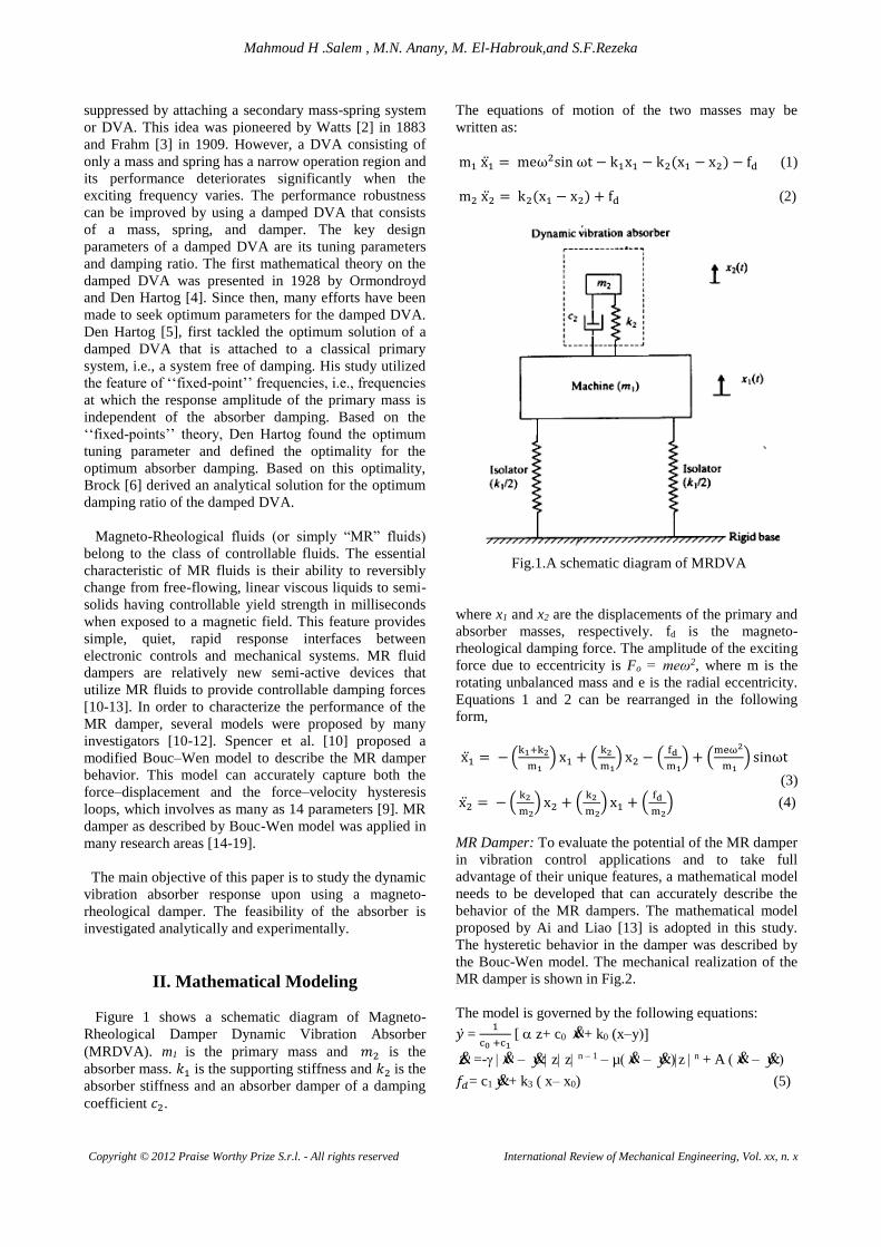
behavior of the MR dampers. The mathematical model
proposed by Ai and Liao [13] is adopted in this study.
The hysteretic behavior in the damper was described by
the Bouc-Wen model. The mechanical realization of the
MR damper is shown in Fig.2.
The model is governed by the following equations:
𝑦 ̇ = 1
c0 +c1 [ z+ c0 x+ k0 (x–y
z =- x – y z z n – 1 – µ x – yz n + A x – y
𝑓𝑑= c1 y+ k3 ( x– x0) (5)
Mahmoud H .Salem , M.N. Anany, M. El-Habrouk,and S.F.Rezeka
Copyright © 2012 Praise Worthy Prize S.r.l. - All rights reserved International Review of Mechanical Engineering, Vol. xx, n. x
Fig.2. A mechanical model of the MR damper (c2).[13]
where z is a variable that accounts for the history
dependence of the applied response. The model
parameters depend on the voltage v to the driver as
follows:
= (u) = a+ b u,
c1= c1 (u) = c1a+c1bu,
c0 = c0 (u) = c0a+ c0bu (6)
Where u is given as the output of the first order filter:
u= - (u-) (7)
In this model, the accumulator stiffness is represented
by k3, and the viscous damping observed at large
velocities by co. A dashpot, represented by c1, is included
in the model to introduce the nonlinear roll-off that was
observed at low velocities, ko is present to control the
stiffness at large velocities, and xo is the initial
displacement of spring k3 associated with the nominal
damper force due to the accumulator. In this model, there
are 14 parameters, (coa, cob, ko, c1a, c1b, k3, xo, αa, αb, γ, µ,
Α, n, η) to characterize the MR damper. The optimized
values for the 14 parameters are determined by fitting the
model to the experimental data obtained in the
experiments [14]. The resulting parameters are given in
Table 1.
Using Equations 1 to 7, a Simulink model is constructed
for the purpose of obtaining MRDVA responses.
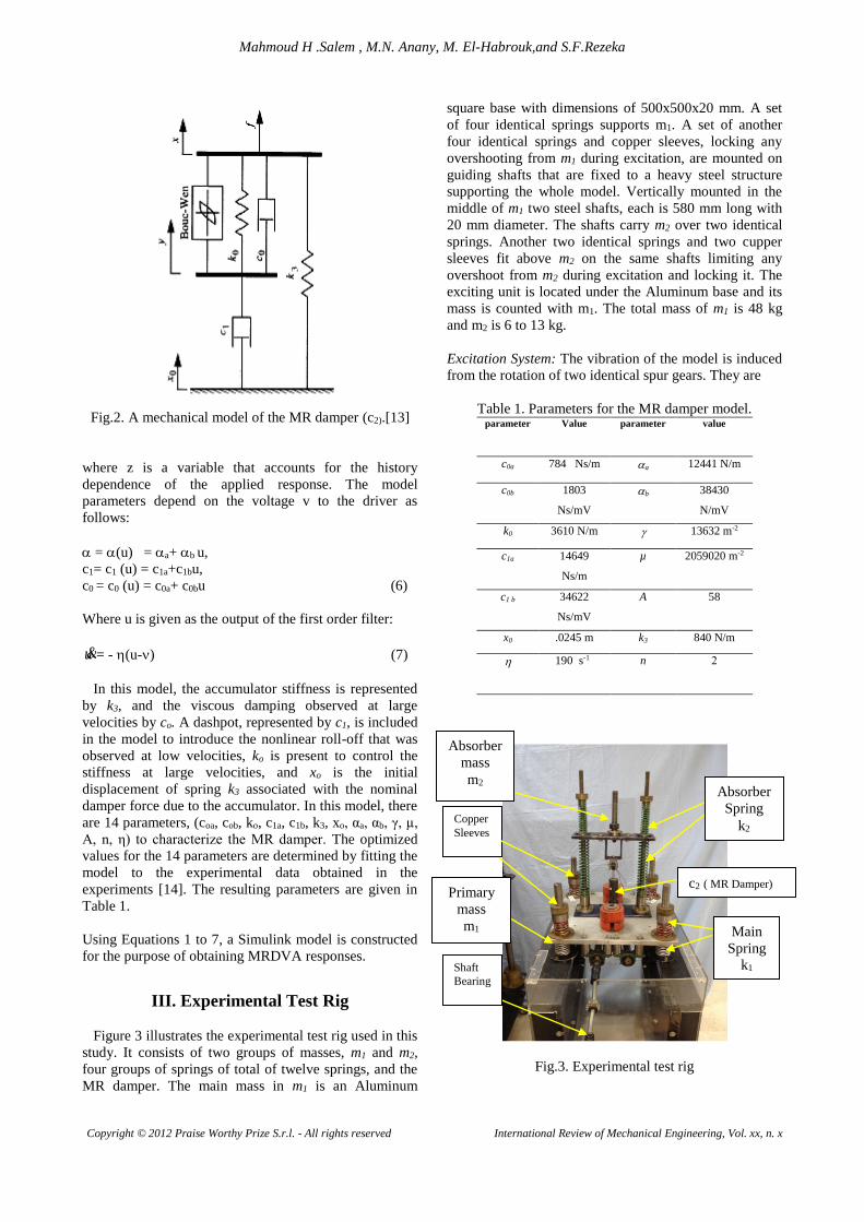
III. Experimental Test Rig
Figure 3 illustrates the experimental test rig used in this
study. It consists of two groups of masses, m1 and m2,
four groups of springs of total of twelve springs, and the
MR damper. The main mass in m1 is an Aluminum
square base with dimensions of 500x500x20 mm. A set
of four identical springs supports m1. A set of another
four identical springs and copper sleeves, locking any
overshooting from m1 during excitation, are mounted on
guiding shafts that are fixed to a heavy steel structure
supporting the whole model. Vertically mounted in the
middle of m1 two steel shafts, each is 580 mm long with
20 mm diameter. The shafts carry m2 over two identical
springs. Another two identical springs and two cupper
sleeves fit above m2 on the same shafts limiting any
overshoot from m2 during excitation and locking it. The
exciting unit is located under the Aluminum base and its
mass is counted with m1. The total mass of m1 is 48 kg
and m2 is 6 to 13 kg.
Excitation System: The vibration of the model is induced
from the rotation of two identical spur gears. They are
Table 1. Parameters for the MR damper model. value parameter Value parameter
12441 N/m a 784 Ns/m c0a
38430
N/mV
b 1803
Ns/mV
c0b
13632 m-2 3610 N/m k0
2059020 m-2 µ 14649
Ns/m
c1a
58 A 34622
Ns/mV
c1 b
840 N/m k3 .0245 m x0
2 n 190 s-1
Fig.3. Experimental test rig
Shaft
Bearing
Copper
Sleeves
Primary
mass
m1
Absorber
mass
m2 Absorber
Spring
k2
c2 ( MR Damper)
Main
Spring
k1

Mahmoud H .Salem , M.N. Anany, M. El-Habrouk,and S.F.Rezeka
Copyright © 2012 Praise Worthy Prize S.r.l. - All rights reserved International Review of Mechanical Engineering, Vol. xx, n. x
made from a non metallic material. Each gear is 124
mm outer diameter and has tooth of module 2 mm,
carved through the 20 mm face of the gears. Each gear
carries a steel rotating unbalance mass of 214 g, fixed at
a radius of 42 mm from the gear centre. The two
unbalance masses are mounted opposing each other on
the two gears symmetrically. This configuration allows
summing their centrifugal forces in the vertical direction
only while they cancel each other in the horizontal
direction, giving a maximum force in the direction of the
springs (vertical direction). Each gear is mounted on two
steel shafts and secured by a 6 mm square key; each shaft
is 32 mm in diameter. Snap rings are mounted on both
sides of the gears faces to prevent their slippage along the
shaft. The rotating shafts carrying the two gears are made
of steel to reduce their elastic deflection caused by the
rotating unbalance force. The two shafts are attached to
the lower surface of the Aluminum base by means of four
ball bearings, housed in FSB (P204) seats, bolted beneath
it. A high speed unidirectional flexible shaft, with chuck
at one end, drives the gear assembly. The flexible shaft is
driven by a single phase, 0.3675 kW electrical motor,
with maximum rotation speed of 2850 R.P.M. at 50/60
Hz. An SV008iC5 LG, variable frequency inverter, links
between the electric motor and the electricity source. It
allows varying the frequency of the input electric current
from 0 to 400 Hz, which in turn varies the speed of the
motor. Frequency can be fine adjusted via the inverter
and consequently the electric motor speed.
The base excitation of the model is provided from the
above excitation system; the gears assembly with the
motors and the current inverter. The meshed gears
provide a harmonic vibration to the model in the form of
“A sin ωt”. When the inverter is set to certain frequency,
the motor is allowed to rotate at constant angular
velocity, providing a steady state condition for
measurements. Although the inverter provides a wide
range of operating frequencies, the main concern in this
work is in the range from 0 to 20 Hz.
The experimental rig specifications are:
Primary Mass m1= 44 kg, Absorber Mass m2=variable
Supporting Stiffness k1 = 55666N/m ,
Absorber Stiffness k2= 21012 N/m
Rotating Unbalance m= 0.244 kg, and
Radial Eccentricity e= 0.05 m
The data measured in the experimental test rig are;
the acceleration of the primary mass m1 and secondary
mass m2. To obtain these parameters, two accelerometers
were available. The first accelerometer was 752A12 from
ENDEVCO with sensitivity 10 mV/ms-2 (for m1). The
second one was 752A13 from ENDEVCO with
sensitivity 100 mV/ms-2 (for m2). These transducers were
attached to BRUEL & KJAER hardware. Displacement
and velocity can be taken from accelerometer by double
integration respectively. The hardware consists of a
number of channels to which transducers can be attached.
It resolves electric signals from transducers and
manipulates them. The signals are processed and
transferred to the computer via Local Area Network link
(LAN). The LAN allows for high speed data
transmission (100 Mbps). The computer utilized was an
Hp notebook with Intel Pentium M processor 1.6 GHz
and 600 MHz CENTRINO. BRUEL & KJAER software
was installed on this notebook. This software is the
manifestation for the data gathered from the transducers.
It is where users can select from different functions,
different data adjustments, different time windows, and
different displays. The software is user-friendly. It is an
arrangement of icons in task groups. Icons, when
pressed, reveal the graphical displays of the user selected
functions.
IV. Uncontrolled System Results and
Discussions
Undamped System: The experimental measurements and
the simulation results are obtained and compared firstly
with no damping in the system upon using different
values for absorber mass m2. The results are reported in
figures 4 to 7.
= 5.5kg 2h mamping witdo n ,1xFig.4. Displacement
.5kg8= 2amping with mdo n ,1x. Displacement 5Fig.
0 2 4 6 8 10 12 140
0.5
1
1.5
2
2.5
3x 10
-3
Am
plit
ude X
1 (
m)
Frequency (Hz)
X1 Amplitude m2=5.5kg Experimental and Simulation
Experimental m2=5.5kg
Simulation m2=5.5kg
Experimental
Single Degree of Freedom
0 2 4 6 8 10 120
0.5
1
1.5
2
2.5
3
3.5x 10
-3
Am
plit
ude X
1 (
m)
Frequency (Hz)
X1 Amplitude m2=8.5kg Experimental and Simulation
Experimental m2=8.5kg
Simulation m2=8.5kg
Experimental
Single Degree of Freedom

Mahmoud H .Salem , M.N. Anany, M. El-Habrouk,and S.F.Rezeka
Copyright © 2012 Praise Worthy Prize S.r.l. - All rights reserved International Review of Mechanical Engineering, Vol. xx, n. x
Figures 4,5 and 6 show both the experimental and
theoretical variation of the primary mass displacement
amplitude x1 versus the operating frequency for an
absorber mass of 5.5, 8.5 and 12 kg, respectively and for
single degree of freedom test cases. For the above
primary mass–spring system, the natural frequency
determined experimentally is fn= 6.2 Hz as seen in the
figures and fn= 5.8 Hz by calculating the natural
frequency mathematically. The theoretical results show
that the absorber can isolate the primary mass completely
from the base excitation. Meanwhile, the experiments
render minimum amplitude of primary mass oscillations
between 3.8 and 5.5 mm.
kg12= 2amping with mdo n ,1x. Displacement 6Fig.
Both the theoretical and experimental values of the first
and second natural frequencies f1 and f2 are listed in
Table 2. The results indicate that the increase in the
absorber mass yields a decrease in the value of the
bandwidth of operation. It can be noticed that the values
resulted from the experiments are slightly higher for the
first natural frequency and lower for the second one. This
can be attributed to the errors in the determination of the
values of the stiffness of the springs. Since the system is
considered as undamped, the amplitudes of the vibrations
reach infinity in the simulated results. Due to the
presence of the internal damping in the guides of the
primary mass and absorber mass, the experimental results
show how the small amount of damping affects the
response of the primary mass(x1) and reduces the
vibration amplitude.
Figures 7a presents the theoretical results of the tuned
frequency for various absorber masses. The primary mass
displacement x1 was zero at a frequency of 9.8 Hz, 8.6
Hz, 7.9 Hz, 7.1 Hz, 6.7 Hz and 6.1 Hz for absorber mass
of 5.5 kg, 7.2 kg 8.9 kg, 11.5 kg, 12 kg and 14 kg,
respectively. Figure 7b shows the tuned frequency at
which the mass exhibits zero displacement where it
isolates the system completely versus the various masses.
Also it can be seen at the natural frequency of oscillation
of the one degree of freedom at (6.2 Hz), the optimum
absorber mass is about 14 kg.
Table 2. Absorber mass and corresponding natural
frequencies. Absorber
massm2,
kg
First Natural Frequency f1,
Hz
Second Natural Frequency
f2, Hz
Simulation Experiments Simulation Experiments
5.5 5.4 5.5 12.4 11.2
8.5 5.2 5.0 9.7 8.6
12 4.8 5.2 8.2 7.8
Fig.7a. Displacement x1 without damping for different
absorber masses
Fig.7b.Tuned Frequency versus absorber mass m2
Damped System: The MR damper was added to produce
the damping effect during the operation of the
experiments. To ensure the homogeneity of an MR fluid,
a trial run was first performed for approximately 10
cycles of oscillations. This ensures that the fluid has been
dispersed before the actual data acquisition commences.
Figures (8 to 12) illustrate the variation of the
displacement amplitudes of vibration x1 with the
operating frequency for constant values of the input
current I = 0A, 0.25A, 0.75A and 1A for different values
of the absorber masses m2= 5.5, 7.2, 8.5, 11.5 and 12 kg.
0 2 4 6 8 10 120
0.5
1
1.5
2
2.5
x 10-3
Am
plit
ude X
1 (
m)
Frequency (Hz)
X1 Amplitude m2=12kg Experimental and Simulink
Experimental m2=12kg
Simulation m2=12kg
Experimental
Single Degree of Freedom
0 2 4 6 8 10 120
0.001
0.002
0.003
0.004
0.005
0.006
0.007
0.008
0.009
0.01
Am
plit
ude X
1 (
m)
Frequency (Hz)
X1 Amplitude Simulation at Different Masses with No damping
Mass=5.5kg
Mass=7.2kg
Mass=8.9kg
Mass=11.5kg
Mass=12kg
Mass=14kg
4 5 6 7 8 9 10 11 12 13 14 15
6
6.5
7
7.5
8
8.5
9
9.5
10
X: 13.67
Y: 6.2
Tuned F
requency
Mass (kg)
Tuned Frequency at different Masses

Mahmoud H .Salem , M.N. Anany, M. El-Habrouk,and S.F.Rezeka
Copyright © 2012 Praise Worthy Prize S.r.l. - All rights reserved International Review of Mechanical Engineering, Vol. xx, n. x
Fig.8. Displacement x1, with MR damping at current input 0A
Fig.9. Displacement x1, with MR damping at current input 0.25A
Fig .10. Displacement x1, with MR damping at current input 0.5A
Fig .11. Displacement x1, with MR damping at current input 0.75A
Fig.12.Displacement x1, with MR damping at current input 1A
The results show that the response of the primary mass
is never zero in the damped case. The maximum value of
the displacement amplitude of vibration x1 of the primary
mass occurs at absorber mass m2 = 12.5kg and applied
current I = 1 A, as shown in figure 12. It is clear from the
figures that the two masses m1 and m2 are virtually
clamped and the system behaves as a single degree of
freedom. This indicates that the damping ratio resulted
upon using the MR damper with the system under
consideration is infinity.
The effects of the input current applied to the MR
damper on the displacement amplitudes of vibration x1
are examined in Figures (13 to 17) for constant values of
the absorber masses m2= 5.5, 7.2, 8.5, 11.5 and 12.5 kg.
The resonant frequencies are decreased from 5.2 Hz to
4.7 Hz as the absorber mass is increased from 5.5 kg to
12.5 kg. The increase of the input current has an adverse
effect on the amplitude of vibration specially with the
increase of absorber mass. This means that increase of
the damping force does not always suppress the
vibrations. Figure 18 summarizes the results of the
performance of the dynamic absorber with MR damper
integrated to a light vibrating system.
Fig .13. Displacement x1 ,with damping (m2 = 5.5 kg)
2 3 4 5 6 7 8 90
1
2
3
4
5
6
7x 10
-3 X1 Amplitude at I=0A
Frequency (Hz)
Am
plit
ude X
1 (
m)
Experimental m2=5.5kg
Experimental m2=7.2kg
Experimental m2=8.5kg
Experimental m2=11.5kg
Experimental m2=12.5kg
2 3 4 5 6 7 8 90
1
2
3
4
5
6
7x 10
-3 X1 Amplitude at I=0.25A
Frequency (Hz)
Am
plit
ude X
1 (
m)
Experimental m2=5.5kg
Experimental m2=7.2kg
Experimental m2=8.5kg
Experimental m2=11.5kg
Experimental m2=12.5kg
2 3 4 5 6 7 8 90
1
2
3
4
5
6
7x 10
-3 X1 Amplitude at I=0.5A
Frequency (Hz)
Am
plit
ude X
1 (
m)
Experimental m2=5.5kg
Experimental m2=7.2kg
Experimental m2=8.5kg
Experimental m2=11.5kg
Experimental m2=12.5kg
2 3 4 5 6 7 8 90
1
2
3
4
5
6
7x 10
-3 X1 Amplitude at I=0.75A
Frequency (Hz)
Am
plit
ude X
1 (
m)
Experimental m2=5.5kg
Experimental m2=7.2kg
Experimental m2=8.5kg
Experimental m2=11.5kg
Experimental m2=12.5kg
2 3 4 5 6 7 8 90
1
2
3
4
5
6
7
8
9x 10
-3
Frequency (Hz)
Am
plit
ude X
1 (
m)
X1 Amplitude at I=1A
Experimental m2=5.5kg
Experimental m2=7.2kg
Experimental m2=8.5kg
Experimental m2=11.5kg
Experimental m2=12.5kg
2 3 4 5 6 7 8 90
1
2
3
4
5
6
7x 10
-3 X1 Amplitude at m=5.5kg
Frequency (Hz)
Am
plit
ude X
1 (
m)
I=0A
I=0.25A
I=0.5A
I=0.75A
I=1A

Mahmoud H .Salem , M.N. Anany, M. El-Habrouk,and S.F.Rezeka
Copyright © 2012 Praise Worthy Prize S.r.l. - All rights reserved International Review of Mechanical Engineering, Vol. xx, n. x
Fig.14. Displacement x1 ,with damping (m2 = 7.2 kg)
Fig .15. Displacement x1 ,with damping (m2 = 8.5 kg)
Fig .16. Displacement x1 ,with damping (m2 = 11.5 kg)
Fig.17.Displacement x1 ,with damping (m2 = 12.5 kg)
It can be realized from Figure 18 that the change of input
current in this system does not show a great deal of
change in the amplitude x1 when small absorber masses
are adopted. It can be concluded that the MR damper is
too large for the proposed system since the increase of
the damping force resulted from the increase of the input
current degrades the absorber performance. From the
parameters of MR damper listed in Table 1, the damper
produces a minimum force of 100N at zero current to a
maximum force of 3000N at I=2.75A. Therefore, a larger
system is required for further study of the MR damper
performance.
Fig.18. Experimental maximum displacement amplitudes of the
primary mass versus input current to damper for different values of the
absorber mass.
V. Controlled System Results and
Discussions
The new system specifications are: Primary mass m1 =3183𝑘𝑔, supporting stiffness k1 = 4.5MN/m, and
absorber stiffness k2= 0.6283 MN/m.
Optimal-Tuned Passive Absorber: An approach is
examined that uses an approximation of the optimal
damper force. Using the heavy system data, a tuned
vibration absorber with a constant damping coefficient
can be set by the following optimal conditions [16].
c = 2m2ωn√3μ′
8(1+μ′)3 (8)
The absorber tuned to
ωa
ωn=
1
1+μ′ (9)
where μ′ is the ratio of the masses of the absorber and
main mass, ωa is the natural frequency of the absorber
mass and absorber spring, and ωn is the natural
frequency of the main mass and foundation spring.
2 3 4 5 6 7 8 90
1
2
3
4
5
6
7x 10
-3 X1 Amplitude at m=7.2kg
Frequency (Hz)
Am
plit
ude X
1 (
m)
I=0A
I=0.25A
I=0.5A
I=0.75A
I=1A
2 3 4 5 6 7 8 90
1
2
3
4
5
6x 10
-3 X1 Amplitude at m=8.5kg
Frequency (Hz)
Am
plit
ude X
1 (
m)
I=0A
I=0.25A
I=0.5A
I=0.75A
I=1A
2 3 4 5 6 7 8 90
1
2
3
4
5
6
7
8x 10
-3 X1 Amplitude at m=11.5kg
Frequency (Hz)
Am
plit
ude X
1 (
m)
I=0A
I=0.25A
I=0.5A
I=0.75A
I=1A
2 3 4 5 6 7 8 90
1
2
3
4
5
6
7
8
9x 10
-3 X1 Amplitude at m=12.5kg
Frequency (Hz)
Am
plit
ude X
1 (
m)
I=0A
I=0.25A
I=0.5A
I=0.75A
I=1A

Mahmoud H .Salem , M.N. Anany, M. El-Habrouk,and S.F.Rezeka
Copyright © 2012 Praise Worthy Prize S.r.l. - All rights reserved International Review of Mechanical Engineering, Vol. xx, n. x
The absorber mass to main mass ratio μ′ was set to 0.2,
and the absorber mass m2=636 kg. The main mass
foundation natural frequency is 6 Hz.
LQR Control Method: Equations 3 and 4 can be put in
state-space form as:
�̇�(𝑡) = 𝐴 𝑋 + 𝐵 𝑢𝑑 + 𝑑(𝑡), (10)
𝑌(𝑡) = 𝐶 𝑋(𝑡)
where X(t) = [ 𝑥1 �̇�1 𝑥2 �̇�2] , ud = fd (the controlled
damping force of the MR dampers), and d(t) is the
exciting disturbing force. The Linear Quadratic
Regulator (LQR) control algorithm is employed to
evaluate the effectiveness of the semi-active vibration
absorber system with MR dampers [15]. The
performance index is chosen as:
𝐽 = ∫ {[𝑋𝑇(𝑡)𝑄 𝑋(𝑡) + 𝑢𝑑(𝑡)𝑇 𝑅 𝑢𝑑(𝑡)] 𝑑𝑡}∞
0 (11)
where Q and R are symmetric semi-positive definite and
positive definite matrices and defined as:
𝑄 = [
1𝑒7 00 1𝑒7
0 0 0 0
0 00 0
1 0 0 1
] 𝑎𝑛𝑑 𝑅 = [1]
The control law that minimizes Equation (11) is given
by:
ud (t) = - K X(t) (12)
Where K = R-1BTS, and S is determined by solving
Riccatti equation: S B R-1 B S - SA - ATS = Q
For the new system specifications, the state feedback
gains are:
K =
[-7468.5563 ; -1824.5806 ; 7.9495e08 ; 1152.2516].
The controlled force acquired from the MR damper
cannot be commanded; only the voltage v applied to the
current driver for the MR damper can be directly
changed. To induce the MR damper to generate
approximately the desired optimal control force fdc, the
command signal v is selected as follows; When the MR
damper is providing the desired optimal force (i.e., fd =
fdc), the voltage applied to the damper should remain at
the present value. If the magnitude of the force produced
by the damper fd is smaller than the magnitude of the
desired optimal force fdc and the two forces have the
same sign, the voltage applied to the current driver is
increased to the maximum level so as to increase the
force produced by the damper to match the desired
control force. If fd ≥ fdc , then the voltage is set to zero.
Results of Controlled System: The effects of varying the
amplitude of the exciting force (Fo) from 100 N to 1000
N on the main mass at different frequencies have been
studied for both optimally-passive-tuned absorber and for
controlled MR damper. Figures 19 to 24 show that
optimally-passive-tuned absorber render higher values
for the main mass displacement than that resulted from
the Linear Quadratic control MR damper. As the
frequency is increased to 12 Hz the amplitude of the
transmitted displacement to the main mass converge for
both dampers. The figures also illustrate that the
maximum amplitude of the main mass is attained at f= 6
Hz. As the exciting force increases from 100 N to 1000
N, the amplitude of the main mass increases from
0.07mm to 0.706mm, respectively, in case of passive
damper at f=6Hz. The corresponding values for the MR
dampers are 0.037mm and 0.432mm, respectively.
Figures (25) and (26) present the response of the
displacement of the main mass and the damping force for
the two modes of the simulation for Fo = 1000 N and f=6
Hz. The maximum damping force due to applying
passive damper is 514 N, and that produces by controlled
MR damper is 125 N.
100N of mplitudeforce aat 1x. Displacement 9.1Fig
200N of mplitudeforce aat 1xFig.20. Displacement
2 4 6 8 10 12 14 160
1
2
3
4
5
6
7
8x 10
-5
Am
plit
ude X
1 (
m)
Frequency (Hz)
X1 Amplitude vs Frequency ( Amplitude=100 N )
Passive
LQR
2 4 6 8 10 12 14 160
0.5
1
1.5x 10
-4
Am
plit
ude X
1 (
m)
Frequency (Hz)
X1 Amplitude vs Frequency ( Amplitude=200 N )
Passive
LQR

Mahmoud H .Salem , M.N. Anany, M. El-Habrouk,and S.F.Rezeka
Copyright © 2012 Praise Worthy Prize S.r.l. - All rights reserved International Review of Mechanical Engineering, Vol. xx, n. x
400N of mplitudeforce a at 1xFig .21. Displacement
600N of mplitudeforce aat 1xFig.22. Displacement
800N of mplitudeforce aat 1xFig.23. Displacement
Fig.24. Displacement x1 at force amplitude of 1000N
Fig.25. Vertical displacement vs. time at f=6 Hz
Fig.26. The damping force of MR damper vs. time at f
=6Hz
2 4 6 8 10 12 14 160
1
2
x 10-4
Am
plit
ude X
1 (
m)
Frequency (Hz)
X1 Amplitude vs Frequency ( Amplitude=400 N )
Passive
LQR
2 4 6 8 10 12 14 160
0.5
1
1.5
2
2.5
3
3.5
4
4.5x 10
-4
Am
plit
ude X
1 (
m)
Frequency (Hz)
X1 Amplitude vs Frequency ( Amplitude=600 N )
Passive
LQR
2 4 6 8 10 12 14 160
1
2
3
4
5
6x 10
-4
Am
plit
ude X
1 (
m)
Frequency (Hz)
X1 Amplitude vs Frequency ( Amplitude=800 N )
Passive
LQR
2 4 6 8 10 12 14 160
1
2
3
4
5
6
7
8x 10
-4
Am
plit
ude X
1 (
m)
Frequency (Hz)
X1 Amplitude vs Frequency ( Amplitude=1000 N )
Passive
LQR
18.5 19 19.5 20-1
-0.8
-0.6
-0.4
-0.2
0
0.2
0.4
0.6
0.8
1x 10
-3
Am
plit
ude X
1 (
m)
Time (s)
X1 Amplitude 1000 at Freq=6Hz
Passive
LQR
18.5 19 19.5 20-600
-400
-200
0
200
400
600
Dam
pin
g F
orc
e (
N)
Time (s)
Force Amplitude 1000 at Freq=6Hz
Passive
LQR

Mahmoud H .Salem , M.N. Anany, M. El-Habrouk,and S.F.Rezeka
Copyright © 2012 Praise Worthy Prize S.r.l. - All rights reserved International Review of Mechanical Engineering, Vol. xx, n. x
VI. Conclusions
A semi-active vibration absorber system with MR
dampers has been investigated experimentally and
analytically. The governing equations of the two degree-
of-freedom vibration absorber model integrated with MR
dampers were developed. The linear quadratic control
was adopted to illustrate the feasibility and effectiveness
of controlled MR dampers on vibration absorber systems.
The dynamic responses of the main mass with secondary
MR absorber system implementing the linear quadratic
control to external sinusoidal forces were evaluated and
compared with those using conventional optimum-tuned-
passive absorber system using viscous dampers. It was
found that, the MR damper, controlled by the proposed
linear quadratic algorithm, can significantly attenuate the
vibrations of the foundation main mass subjected to large
exciting forces. MR dampers in vibration absorber
systems are feasible and effective for heavily vibrating
systems. The performance of LQR control is compared to
that of the optimum-tuned-passive vibration absorber
system using viscous dampers. The simulation results
show that integrating controlled MR dampers in vibration
absorber system achieves a significant decrease in main
mass displacement in heavy vibrating systems. LQR
control of the MR damper is more effective than the
optimum passive conventional absorber in both
suppressing the vibration of the main mass and reducing
the transmitted forces.
References
[1] Yagiz, N., Hacioglu, Y., Backstepping control of a
vehicle with active suspensions, Control
Engineering Practice, 2-11, 2008.
[2] Watts, P., "On a method of reducing the rolling of
ship at sea," Transactions of the Institute of Naval
Architects, Vol. 24, pp. 165–190, 1883.
[3] Frahm, H., "Device for damping vibrations of
bodies," U.S. Patent No. 989958, 1909.
[4] Ormondroyd, J. and Den Hartog, J.P., "Theory of the
dynamic vibration absorber," Transactions of the
American Society of Mechanical Engineers, Vol. 50,
pp. 9–22, 1928.
[5] Den Hartog, J.P., Mechanical Vibrations, McGraw-
Hill, New York, 1934.
[6] Brock, J. E., "A note on the damped vibration
absorber," Journal of Applied Mechanics, Vol. 68,
pp. A-284, 1946.
[7] Liu, K. and Liu, J., "The damped dynamic vibration
absorbers: revisited and new result," Journal of
Sound and Vibration, Vol. 284, pp. 1181–1189,
2005.
[8] Wong, W. and Cheung, Y., "Optimal design of a
damped dynamic vibration absorber for vibration
control of structure excited by ground motion,"
Engineering Structures, Vol. 30, pp. 282–286, 2008.
[9] Yao, G.Z., Yap, F.F., Chen, G., Li, W.H., and Yeo,
S.H., "MR damper and its application for semi-
active control of vehicle suspension system," School
of Mechanical & Production Engineering, 26 March
2001.
[10] Spencer, B.F., Dyke, D.J., Sain, M.K., and Carlson,
J.D., "Phenomenological model of a magneto-
rheological damper," Journal Eng Mech, 123(3),
230–8, (1997).
[11] Kamath, G.M, and Wereley, N., "Nonlinear
viscoelastic–plastic mechanism-based model of an
electro-rheological damper," AIAA Journal
Guidance, Control Dyn, 20(6), 1125–332, (1997).
[12] Li, W.H., Yao, G.Z., Chen G., Yeo S.H., and Yap
F.F., "Testing and steady state modeling of a linear
MR damper under sinusoidal loading," J of Smart
Material Structure, 9(1), 95–102, (2000).
[13] Ai, C.Y. and Liao, W.H., “Vibration control of a
suspension system via a magneto-rheological fluid
damper,” Journal of Vibration and Control, Vol. 8,
No. 4, 527-547, 2002.
[14] Gameel, H., “A Study of a Dynamic Vibration
Absorber Using a Magneto-Theological Damper,”,
M.Sc. Thesis AAST, July 2006.
[15] Liao, W. H., and Wang, D.H., "Semi-active
vibration control of train suspension system via
magneto-rheological dampers", Journal of
Intelligent Material Systems and Structures, vol.
14-march (2003): 161-172.
[16] Vavreck, A.N., "Control of a dynamic vibration
absorber with magneto-rheological damping,"
Proceedings of SPIE, Vol. 4073(2000).
[17] Yao G.Z., Yap F.F., Chen G., Li W.H., and Yeo
S.H., "MR damper and its application for semi-
active control of vehicle suspension system,"
Mechatronics, 12, pp 963-973, (2002).
[18] Chrzan, M.J., and Carlson, J.D., "Mr fluid sponge
devices and their use in vibration control of
washing machines," Proceedings of SPIE, Vol.
4331, pp 370-378,(2001).
[19] El Gamal, H. A., Rezeka, S. F., El Faham, I. M.,
and Abd El Kader, M. M., “Sliding control of
magneto-rheological dampers in train,” American
Journal of Scientific Research (AJSR), Issue 44
(2012), pp. 139-152.
Authors’ information
1- Mahmoud H Salem received the B.Sc.
degree from Arab Academy for Science & Technology & Maritime Transport, Alex, Egypt
in 2009 in Mechanical Engineering. He is a
Graduate Teaching Assistant of Mechanical Engineering in Arab Academy for Science &
Technology & Maritime Transport, Alex, Egypt
.His professional interests include mechanical vibrations intelligent control systems for autonomous vehicles, modeling and simulation of dynamic
systems and mechatronics.

Mahmoud H .Salem , M.N. Anany, M. El-Habrouk,and S.F.Rezeka
Copyright © 2012 Praise Worthy Prize S.r.l. - All rights reserved International Review of Mechanical Engineering, Vol. xx, n. x
2- Mohammed N. Anany received his B.Sc. and M.Sc. degrees from the Arab Academy for Science &
Technology AAST, Egypt, in 1998 and 2003,
respectively. He obtained his PhD from Univesity of Stuttgart, Germany in 2010. He is working for the
time being as a lecturer at the AAST. He is interested
in modeling and simulation of mechanical systems.
3- Mohamed El-Habrouk received the B.Sc.
and M.Sc. degrees from Alexandria Univ., Egypt in 1992 and 1995, respectively and the
PhD degrees in Electrical Engineering from
Brunel University, London, UK in 1998. He
is a lecturer of Electrical Engineering in
Alexandria University, Egypt. His
professional interests include autonomous Robotics, Power Electronics, Automatic
Control Applications, Microcontrollers, Modeling and Simulation of
dynamic systems and mechatronics.
4- Sohair F. Rezeka received the B.Sc. degree from Alexandria Univ., Egypt in 1976 and the M.Sc. and
the PhD degrees in Mechanical Engineering from
Wayne State University, Detroit, Michigan in 1980, and 1984, respectively. She is a professor of
Mechanical Engineering in Alex. Univ., Egypt and
now she is on leave at Arab Academy for Science and Technology, Alex., Egypt. Her professional interests include intelligent
control systems for autonomous vehicles and HVAC systems, fault
diagnostics and identification, modeling and simulation of dynamic systems and mechatronics.