Performance Evaluation Study for HiperLan WLAN Protocol Omar A. Elprince Student#220510.
24
Performance Evaluation Study for HiperLan WLAN Protocol Omar A. Elprince Student#220510
-
Upload
osborn-newman -
Category
Documents
-
view
217 -
download
0
Transcript of Performance Evaluation Study for HiperLan WLAN Protocol Omar A. Elprince Student#220510.

Performance Evaluation Study for HiperLan WLAN Protocol
Omar A. ElprinceStudent#220510

Agenda
What is HIPERLAN? Origin of HIPERLAN HIPERLAN MAC Mechanism HIPERLAN Family Features of HiperLAN/2 MAC Frame Structure Transport Channels The Channel Access Mechanism Signaling and Control Error Control Simulation Results
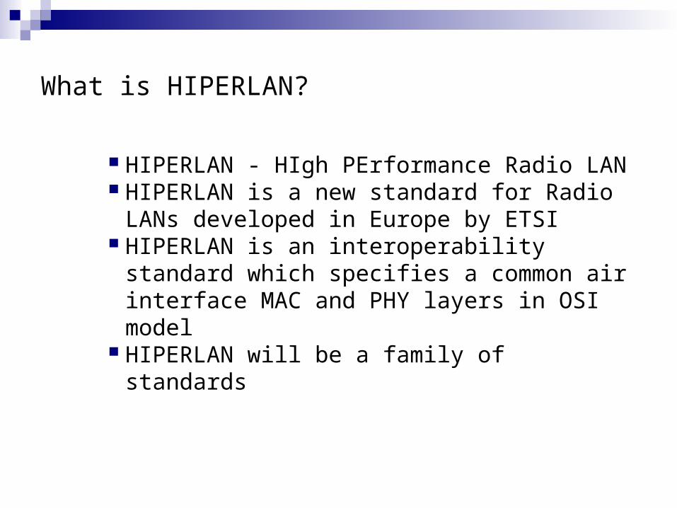
What is HIPERLAN?
HIPERLAN - HIgh PErformance Radio LAN HIPERLAN is a new standard for Radio LANs
developed in Europe by ETSI HIPERLAN is an interoperability standard which
specifies a common air interface MAC and PHY layers in OSI model
HIPERLAN will be a family of standards

Origin of HIPERLAN
Early wireless LANs operating in the ISM bands (900MHz and 2.45GHz)
Low data rate (~1Mbps) - an indirect result of the FCC spread spectrum rules part 15.247.
Severe interference environment - from unlike wireless LANs and other ISM band systems.
Lack of standards - IEEE 802.11 was initiated to satisfy this need but it was taking time to develop.
ETSI set up RES10 group to develop a standard that would be equal in performance to wired LANs such as Ethernet.

HiperLAN Family
Hiperlan 1 Hiperlan2 HiperAccess HiperLink
Description Wireless LAN
Wireless LAN and 3G
Wireless Broadband Point to multipoint
Wireless Broadband Inter Connection
Freq. Range 5 GHz 5 GHz 5 GHz 17 GHz
PHY. Bit Rate 23.5Mbps 6~54Mbps ~25Mbps (date rate)
~155Mbps (date rate)

HIPERLAN MAC
Concept: Fully distributed MAC networks with and without infrastructure
permits multi-hop relaying via neighbors based on LBT (Listen before talk)
Channel Access Mechanism is based on channel sensing and a contention resolution scheme called EY-NPMA - Elimination Yield Non-pre-emptive Priority Multiple Access using listen-talk contention resolution and using talk-listen Immediate packet acknowledgment.
It defines a priority scheme and a life time for each packet which facilitate the control of QoS.
In addition to routing it handles the encryption and power conservation.

HIPERLAN MAC (Cont’d)The Channel Access Mechanism
The channel access cycle consists of three phases: the prioritization phase, the contention phase and the transmission phase.
The aim of the prioritization phase is to allow only nodes with the highest channel access priority frame to participate in the next phase.
The contention phase starts immediately after the transmission of the prioritization burst, and it further consists of two phases: the elimination phase and the yield phase.
The transmission phase begins if the channel is sensed idle during the yield listening interval.

HIPERLAN MAC (Cont’d)Function:
Station 1
Station 2
Station 3
Station 4
Time
data packet
stops
stops
stops
prioritisation contention transmission
Listen
Talk
Listen
Listen
Listen
Talk
Talk
Talk
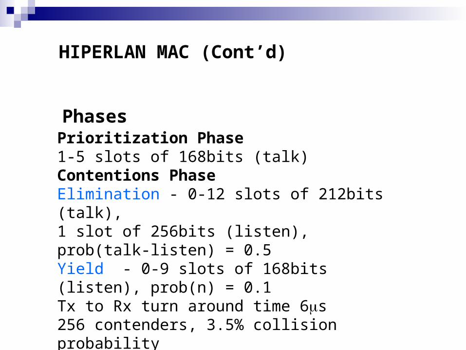
PhasesPrioritization Phase1-5 slots of 168bits (talk)Contentions PhaseElimination - 0-12 slots of 212bits (talk),1 slot of 256bits (listen), prob(talk-listen) = 0.5Yield - 0-9 slots of 168bits (listen), prob(n) = 0.1Tx to Rx turn around time 6s256 contenders, 3.5% collision probabilityTotal of 0-5152bits (0-219s) MAC header
HIPERLAN MAC (Cont’d)

Previous simulations show that the HIPERLAN MAC can simultaneuosly support25 audio links @ 32kbit/s, 10ms delivery 25 audio links @ 16kbit/s, 20ms delivery1 video link @ 2Mbit/s, 100ms deliveryAsynch file transfer @ 13.4Mbit/s
HIPERLAN MAC (Cont’d)
Performance:

HIPERLAN MAC (Cont’d)Operation Parameter SettingParameter ValueChannel Bit Rate (Mbit/sec) 23.5CAM Priority Levels 5Maximum number of subsequence Elimination bursts
12
Priority of bursting in an elimination slot 0.5Maximum number of subsequence Yield listening 14Probability of listening in a Yield slot 0.9

NORMALISEDRESIDUAL LIFETIME
HIGH USER
DEFINED PRIORITY
LOW USER
DEFINED PRIORITY
NRL < 10ms 0 110ms < NRL<
20ms1 2
20ms < NRL < 40ms
2 340ms < NRL <
80ms3 4
NRL > 80ms 4 4
HIPERLAN 1 MAC (Cont’d)Priority is a function of lifetime and user priority

HIPERLAN Mechanism
MT initially requests resources (RR) to the AP, the MT may use the RCH to send the RR msg to AP. If collision occurs then the MT is informed in the ACH of the next MAC frame. The MAC uses a new back off time. After the successful resource request, the MT goes into the contention free mode- where the AP schedules the MT for transmission. Scheduling is done by the centralized control in the AP->QoS increases

HIPERLAN MAC (Cont’d)
MAC Frame Structure:
The basic MAC frame structure on the air interface has a fixed duration of 2 ms and comprises transport channels for broadcast control, frame control, access control, downlink (DL) and uplink (UL) data transmission and random access.
The MAC frame and the transport channels form the interface between DLC and the physical layer.

Basic MAC Frame Structure

Transport Channels
The access feedback channel (ACH, downlink only) conveys information on previous access attempts made in the RCH.
The broadcast channel (BCH, downlink only) contains control information that is sent in every MAC frame and reaches all the MTs. The BCH provides information (not exhaustive) about transmission power levels, starting point and length of the FCH and the RCH,
The frame control channel (FCH, downlink only) contains an exact description of how resources have been allocated within the current MAC frame in the DL- and UL-phase and for the RCH.
The C-PDUs are referred to as the short transport channel (SCH), and the U-PDUs are referred to as the long transport channel (LCH).
The random access channel (RCH, uplink only) is used by the MTs to request transmission resources for the DL- and UL-phase in upcoming MAC frames, and to convey some RLC signalling messages.

Features of HiperLAN/2
High-Speed Transmission up to 54Mpbs Using the OFDM
Connection-oriented Data is transmitted on a connection between the AP and the MT,
that has been established prior to transmission using the signaling functions.
QoS Each connection can be assigned a special type of QoS eg:
bandwidth, delay, BER To virtually support any type of service like multimedia, VoIP and
real time video

Signaling and Control
Radio Link Control (RLC ) gives a transport service for signaling entities:
– Association Control Function (ACF) – Radio Resource Control Function (RRC) – DLC user Connection Control Function
(DCC)

Signaling and Control (Contd)
Association Control Function (ACF)AuthenticationAssociation/DisassociationEncryption
Radio Resource Control (RRC)HandoverDynamic Frequency SelectionPower saving

Error Control
Acknowledge: Based on Selective Repeat (SR) Provides reliable transmission
Repetition Reliable Retransmission by repeating the DLC PDUs Transmitter arbitrarily retransmits the PDUs, but the receivers accepts
only in a sequential order Unacknowledge
Unreliable Transmission Transmitter sends the PDUs in increased sequential order, and the
receiver will deliver the received ones to the Convergence Layer (CL)
Centralized/Direct Mode used byHiperLAN/2
AP Cell: consists of many MTs and an AP AP Cell has a centralized control (logical function)which decides when the AP or the MT can access the medium Geographical Area:
Outdoor: 100m- 150m Indoor: 30m
AP is connected to the Backbone Network (BN) BN provide different services to the MT eg:Internet APs are interconnected through the BN, thus increasing the
coverage Handover mechanism helps in the mobility of the MTs.

Hiperlan Performance Simulation
DEMO

Hiperlan Performance Simulation (Cont’d)
%Network throughput vs %load
01020304050607080
0 11 16 17 25 59 63 73 74 94
%Load
%N
etw
ork
Th
rou
gh
pu
t
25 users throughput
8 users throughput
2 users throughput

Hiperlan Performance Simulation (Cont’d)
MAC Delay
0
0.2
0.4
0.6
0.8
1
1.2
49 52 52 58 72 83 89 91 93 100
% Load
Ave
rag
e M
AC
del
ay
delay of 2 nodes
delay of 8 nodes
delay of 25 nodes