Performance Evaluation of Viscoelastic and Friction ... · 1 Journal of Structural Engineering and...
23
1 Journal of Structural Engineering and Geotechnics, 5 (2), 1-23, Spring 2015 QIAU Performance Evaluation of Viscoelastic and Friction Passive Damping System in Steel Structures Mohammad Taghi Kazemi a , Hosein Hoseini *b a Associate Professor of Faculty of Engineering, Sharif University of Technology, Tehran, Iran b MSc graduate, Faculty of Civil Engineering, Qazvin Branch, Islamic Azad University, Qazvin, Iran Received 19 March 2015; Accepted 5 May 2015 Abstract Additional dampers are employed in order to decrease the dynamic response of structure against the earthquake and wind loading recently. In this study, two types of systems related to waste of inactive energy, i.e. frictional damper which is categorized in dampers dependent on movement and viscoelastic damper which is categorized in dampers dependent on velocity, in making steel structures resistant are investigated and evaluated. Results of structures with dampers (viscoelastic damper, friction damper and combination of both dampers) were compared with the results of structures without damper. Increasing trend in dissipating energy was observed. Then, the behavior of these dampers in frames of 4, 8 and 12 stories was studied by modeling the damper directly. The analyses were conducted via nonlinear time history technique and by using earthquake records (near fault and far fault) scaled with peak acceleration and SAP 2000 14.2.2 software. The results indicate the appropriate function of the selected dampers in controlling and decreasing the seismic responses of the structure. Given that in frictional dampers the maximum force created in the damper is specified, the use of this damper in resistance building of structures is very effective especially by considering the limitation of structure capacity. Keywords: Passive damping, Seismic excitation, Viscoelastic damper, Friction damper, Non-linear Dynamic Analysis. 1. Introduction Earthquakes are one of the most devastating natural hazards that cause great loss of life and livelihood. On average, 10,000 people die each year due to earthquakes, while annual economic losses are in the billions of dollars and often constitute a large percentage of the gross national product of the country affected. Additionally, the damage caused by earthquakes is almost entirely associated with manmade structures. As in the cases of landslides, earthquakes also cause death by the damage they induce in structures such as buildings, dams, bridges and other works of man. Unfortunately many of earthquakes give very little or no warning before occurring and this is one of the reasons why earthquake engineering is complex. Also buildings, which are tall in comparison to their plan area, will generate high overturning moments while buildings with large plan areas may not act as expected due to differences in ground behavior, which are not always predictable. This causes different parts of the building to be shaken differently creating obvious problems. Torsion from ground motion could be of great concern due to eccentricity in the building layout. For instance if the center of mass (gravity) is not in the same position as the center of resistance; a torsional moment Corresponding Author Email: [email protected] about a vertical axis will be created which will have to be designed for. In order to achieve satisfactory earthquake response of a structure, three methods can be identified as being practical and efficient: isolation, energy absorption at plastic hinges, and use of mechanical devices to provide structural control [1]. Vibration control is a fairly new category in different methods of improving the seismic behavior of structures and designing seismic resistant buildings. Based on this concept, response of structures under dynamic loads is controlled using embedded appropriate devices and equipment’s by which displacements are reduced and dynamic response is improved. In the last two decades considerable progress has been achieved in control of structures. These control systems are classified into three categories which include: active control, semi-active control and passive control. Using energy dissipation devices or dampers is one of the control methods for structures subjected to seismic loads. These devices are used in the design of new buildings and retrofitting of existing buildings. Instead of increasing ductility of structural elements, dampers reduce the level of seismic energy imposed on these elements. Nowadays, friction and viscoelastic dampers are used due to a high energy dissipation potential, low cost, easy installation and maintenance. Viscoelastic (VE) dampers
-
Upload
phungkhanh -
Category
Documents
-
view
213 -
download
0
Transcript of Performance Evaluation of Viscoelastic and Friction ... · 1 Journal of Structural Engineering and...

1
Journal of Structural Engineering and Geotechnics,
5 (2), 1-23, Spring 2015
QIAU
Performance Evaluation of Viscoelastic and Friction Passive Damping System in Steel Structures
Mohammad Taghi Kazemia, Hosein Hoseini*b
aAssociate Professor of Faculty of Engineering, Sharif University of Technology, Tehran, Iran bMSc graduate, Faculty of Civil Engineering, Qazvin Branch, Islamic Azad University, Qazvin, Iran
Received 19 March 2015; Accepted 5 May 2015
Abstract
Additional dampers are employed in order to decrease the dynamic response of structure against the earthquake and wind loading recently. In this study, two types of systems related to waste of inactive energy, i.e. frictional damper which is categorized in dampers dependent on movement and viscoelastic damper which is categorized in dampers dependent on velocity, in making steel structures resistant are investigated and evaluated. Results of structures with dampers (viscoelastic damper, friction damper and combination of both dampers) were compared with the results of structures without damper. Increasing trend in dissipating energy was observed. Then, the behavior of these dampers in frames of 4, 8 and 12 stories was studied by modeling the damper directly. The analyses were conducted via nonlinear time history technique and by using earthquake records (near fault and far fault) scaled with peak acceleration and SAP 2000 14.2.2 software. The results indicate the appropriate function of the selected dampers in controlling and decreasing the seismic responses of the structure. Given that in frictional dampers the maximum force created in the damper is specified, the use of this damper in resistance building of structures is very effective especially by considering the limitation of structure capacity.
Keywords: Passive damping, Seismic excitation, Viscoelastic damper, Friction damper, Non-linear Dynamic Analysis.
1. Introduction
Earthquakes are one of the most devastating natural hazards that cause great loss of life and livelihood. On average, 10,000 people die each year due to earthquakes, while annual economic losses are in the billions of dollars and often constitute a large percentage of the gross national product of the country affected. Additionally, the damage caused by earthquakes is almost entirely associated with manmade structures. As in the cases of landslides, earthquakes also cause death by the damage they induce in structures such as buildings, dams, bridges and other works of man. Unfortunately many of earthquakes give very little or no warning before occurring and this is one of the reasons why earthquake engineering is complex. Also buildings, which are tall in comparison to their plan area, will generate high overturning moments while buildings with large plan areas may not act as expected due to differences in ground behavior, which are not always predictable. This causes different parts of the building to be shaken differently creating obvious problems. Torsion from ground motion could be of great concern due to eccentricity in the building layout. For instance if the center of mass (gravity) is not in the same position as the center of resistance; a torsional moment
Corresponding Author Email: [email protected]
about a vertical axis will be created which will have to be designed for. In order to achieve satisfactory earthquake response of a structure, three methods can be identified as being practical and efficient: isolation, energy absorption at plastic hinges, and use of mechanical devices to provide structural control [1]. Vibration control is a fairly new category in different methods of improving the seismic behavior of structures and designing seismic resistant buildings. Based on this concept, response of structures under dynamic loads is controlled using embedded appropriate devices and equipment’s by which displacements are reduced and dynamic response is improved. In the last two decades considerable progress has been achieved in control of structures. These control systems are classified into three categories which include: active control, semi-active control and passive control. Using energy dissipation devices or dampers is one of the control methods for structures subjected to seismic loads. These devices are used in the design of new buildings and retrofitting of existing buildings. Instead of increasing ductility of structural elements, dampers reduce the level of seismic energy imposed on these elements. Nowadays, friction and viscoelastic dampers are used due to a high energy dissipation potential, low cost, easy installation and maintenance. Viscoelastic (VE) dampers

M.T. Kazemi and H. Hoseini
2
generally represent a wide class of energy dissipation devices whose force-displacement relationship has viscous or viscoelastic mechanical properties. In recent decades, VE dampers have been widely applied to mitigate the effects of vibration in civil engineering structures caused by various excitations, including traffic load, wind load and seismic load [2]. Viscoelastic (VE) dampers provide supplemental stiffness and damping and when combined with flexible MRFs so that they would carry a large fraction of the lateral dynamic forces, they are becoming very effective in reducing peak structural response. Dampers made of high-damping elastomer have been tested and found to exhibit a modest energy dissipation capacity but less sensitivity to frequency and temperature compared to conventional VE dampers. It has been though found impossible to design elastomeric dampers and steel MRFs at practical sizes and cost for the building to remain elastic under strong earthquakes. Both VE and elastomeric dampers transfer high forces on beams and columns of the MRF. These
forces cannot be used directly in conventional capacity design rules since they are out of phase with the peak structural displacements (Fig.1) On the other hand, friction devices are displacement-dependent types of passive systems which have high energy dissipation potential. Their application in the structures is increased progressively in many projects in the world. It is worth mentioning that semi-active type of this damper is also produced recently which is used in braces and base isolation. Performance of passive friction dampers has been investigated, and algorithms for analyzing structures with this type of damper have been developed that indicate satisfactory performance of these dampers in reducing the seismic response of structures. All friction dampers have a fixed part that the other part slides on it dynamically. Start of sliding occurs in a certain level of force and before reaching this level no motion can occur. But after this level, sliding movement begins. These dampers usually create stable hysteresis loops (Fig.2) [3, 4].
Figure 1. Viscoelastic damper [2]
Figure 2. Rotational friction damper [3]

Journal of Structural Engineering and Geotechnics, 5 (2), 1-23, Spring 2015
3
2. Scope of the study
Use of passive energy dissipation devices has become very popular in the recent years. However, the vast majority of applications was realized within frame structures, while investigations on the use of multi damping devices is still very limited. For this reason the aim of this research is to investigate the behavior of multi-storey frame under earthquake loads (near and far fields) with viscoelastic dampers and friction dampers in combination and separately. The research will evaluate the influence of different damping systems on the overall seismic response of the structure.
3. Literature review
In recent years, both researchers and practicing engineers have recognized that energy dissipation dampers can provide an efficient means for controlling the structure response induced by strong motion earthquakes. Most structures can be designed to withstand severe earthquake forces by providing ductility and energy absorption capacity to the structural elements, but at the expense of substantial damage in the structural elements, and also for nonstructural elements and services. On the other hand, by dissipating the vibratory energy in structural dampers, the risk of the structure experiencing excessive deformations or accelerations can be reduced. As a result, less ductility or inelastic energy demand is required in the structural frame. In particular, structural isolation systems can be designed essentially to limit the nonlinear behavior to the isolation devices, thereby imposing very small or no ductility demand on the structure itself. Passive and active damping of vibration in structures can be very important for several reasons. In terms of performance, higher damping can reduce the steady-state vibration time, and it can also reduce the time needed for transient vibration to settle. Generally, passive damping can reduce the complexity of the active control needed. However, it couples vibration modes (natural frequencies) which have been calculated for an un-damped system [5]. Structural damping mostly arises as the result of many energy dissipation mechanisms acting in a system. These sources of damping might be classified by considering a structure as an assemblage of elements which interact at interfaces (nodes). Material damping occurs within the elements, and can be added to joint impact and friction damping coming from the interaction of one element with another at a common interface, or from the interaction of the structure with a nonstructural internal or external environment. Material damping is generally a complex function of frequency, temperature, type of deformation, amplitude and structural geometry. It is probably true to say that current popular treatments of damping in structural dynamics are not physically motivated, and are unable to reproduce this fundamental physical behavior. In recent years, many studies have been done about the friction and viscoelastic dampers [6, 7].
Min et al [8] presented Simple design procedure of a friction damper for reducing seismic responses of a single-storey structure. This study proposed a simple design procedure for determining the required damping force of a friction damper installed in a single-story structure. The analysis model was transformed into an equivalent mass-spring-dashpot system by approximating a nonlinear Coulomb damping force with an equivalent viscous damping force. A closed form solution for the dynamic magnification factor (DMF) for a steady state response was derived using the energy balance equation. The equivalent viscous damping ratio was defined using the DMF at the natural frequency. The transfer function between input harmonic excitation and output structural response was obtained from the DMF, and the response reduction factor of the root mean square (RMS) of displacements with and without friction dampers was analytically determined. Using the proposed procedure the friction force required for satisfying a given target response reduction factor was obtained. The response reduction factors were obtained for the structures with different natural frequencies subjected to ten earthquake records. Based on the dynamic analysis results, it was concluded that the mean response reduction factors matched well with the target values. Mirtaheri et al [9] studied on hysteretic behavior of cylindrical friction dampers. In this investigation, an innovative type of frictional damper called cylindrical friction damper (CFD) is proposed. This damper consists of two main parts, the inner shaft and the outer cylinder. Dimensions and properties of the main parts are defined based on seismic demand of structures. These two parts are assembled such that one is shrink fitted inside the other. Upon application of proper axial loading to both ends of the CFD, the shaft will move inside the cylinder by overcoming the friction. This in turn leads to considerable dissipation of mechanical energy. In contrast to other frictional dampers, the CFDs do not use high-strength bolts to induce friction between contact surfaces. This reduces construction costs, simplifies design computations and increases reliability in comparison with other types of frictional dampers. The hysteretic behavior of CFD is studied by experimental and numerical methods. The results show that the proposed damper has great energy absorption by stable hysteretic loops, which significantly improves the performance of structures subjected to earthquake loads. Also, a close agreement between the experimental and numerical results is observed. Mirzabagheri et al. [10] investigated of rotational friction dampers with multi units in steel frames subjected to lateral excitation. Performance of rotational friction dampers with two and three units was evaluated experimentally because of a lack of research data on performance of these dampers with multi units. Results of multi-unit dampers were compared with the results of one-unit damper. Increasing trend in dissipating energy was observed. Then, the behavior of these dampers in

M.T. Kazemi and H. Hoseini
4
frames of 3, 7 and 12 stories was studied by modeling the damper directly. Nonlinear time history dynamic analysis was used. It was observed that by increasing the number of stories in the buildings, dampers with multi units should be used to perform properly against earthquake. The equivalent damping method was also investigated to consider the effects of this damper without direct modeling of the damper. Effective damping of the frames equipped with this type of damper was estimated and used in nonlinear time history dynamic analysis and it was observed that the responses of these structures with dampers can be approximated by the responses of moment resisting frames without damper but with damping equal to the effective damping due to rotational friction damper. Rijnen et al [11] studied on viscoelastic damping of a 3D structure. In this paper, different ways of introducing passive damping via viscoelastic materials (VEM) are discussed. Discrete damping elements and constrained layer (CL) configurations are selected and used to efficiently damp an open aluminum box. For the constrained layer configurations, a distinction is made between full and partial coverage of the structure. The steady-state dynamics of the box are simulated using a finite element (FE) model, which includes frequency dependent VEM properties. Model based results and experimental results show good resemblance, even without updating the model with deviations in the realized structure. The local dampers add most damping to a limited number of modes. Partially covering the box with CL dampers is found to be more effective than full coverage of the structure with the same mass addition. Ywan-Lu et al [12] generalized Maxwell model for nonlinear viscoelastic dampers used in seismic isolation. In order to accurately simulate the hysteretic behavior of such a damper, this paper presents and experimentally verifies a mathematical model called the generalized Maxwell model (GMM). Similar to the classic Maxwell model, the GMM is composed of a stiffness and a viscous elements connected in series. However, nonlinearity is incorporated into both elements of the GMM by assuming that their resistant forces are exponential functions of the relative velocity and deformation of the damper. By adjusting the two exponential coefficients, the GMM is able to simulate the more complicated viscoelastic behavior of fluid dampers. The result of the element test confirms that the GMM model is very accurate in simulating the hysteretic property of the fluid damper under a wide range of excitation frequencies, while the classic Maxwell and the viscous models may only be accurate under a certain excitation frequency. Lewandowski et al [13] presented on Dynamic analysis of frames with viscoelastic dampers (a comparison of damper models). It is the aim of this paper to compare the dynamic characteristics of frame structures with VE dampers when the dampers are modelled by means of different models. The classical rheological models, the model with the fractional order derivative, and the complex modulus model are used. A relatively large
structure with VE dampers is considered in order to make the results of comparison more representative. The formulae for dissipation energy are derived. The finite element method is used to derive the equations of motion of the structure with dampers and such equations are written in terms of both physical and state-space variables. The solution to motion equations in the frequency domain is given and the dynamic properties of the structure with VE dampers are determined as a solution to the appropriately defined eigenvalue problem. Several conclusions concerning the applicability of a family of models of VE dampers are formulated on the basis of results of an extensive numerical analysis.
4. Theoretical treatment
4.1. Modeling VED1s
Material behavior is termed viscoelastic if the material stores part of the deformational energy elastically as potential energy, and dissipates the rest simultaneously through viscous forces. The rheological properties of a viscoelastic material are time-dependent. Although, in principle all real materials are viscoelastic: this property becomes significant when the time required for the full development of a response is comparable with the time scale of the test performed to determine it. When a stress or a strain is impressed upon a body, rearrangement takes place inside the material as it responds to the imposed excitation. In any real material these rearrangements necessarily require a finite time. As a consequence of the material rearrangement taking place on a time scale comparable to that of the test in which the response is observed, the relation between stress and strain or rate of strain cannot be expressed by material constants as in I:he case of purely elastic or purely viscous material.
4.1.1. Kelvin element
The main disadvantage of Kelvin model (Figure 3), in modeling the viscoelastic material, is that it differentiates a loss modulus linearly dependent on the frequency and a storage modulus independent of frequency that is not an accurate representation for most materials and, in particular, for polymers or rubbers.
Figure 3. Kelvin model [14]
The Kelvin model of VED (element) consists of a linear spring in parallel with a viscous damper. The response behavior of the Kelvin-Voigt model satisfies: 1. Viscoelastic Dampers (VEDs)
Journal of Structural Engineering and Geotechnics, 5 (2), 1-23, Spring 2015
5
휎 = 휂 휀 + 퐸 휀 (1) 퐸 = 휂 휔 (2)
The dissipation of energy per cycle in harmonic deformation is linearly proportional to the deformation frequency:
푊( ) = 휋퐸 [휂 휔] (3)
4.1.2. Maxwell element
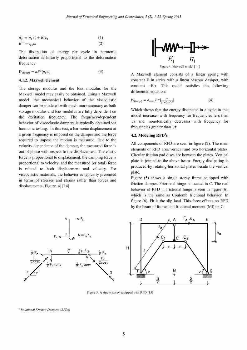
The storage modulus and the loss modulus for the Maxwell model may easily be obtained. Using a Maxwell model, the mechanical behavior of the viscoelastic damper can be modeled with much more accuracy as both storage modulus and loss modulus are fully dependent on the excitation frequency. The frequency-dependent behavior of viscoelastic dampers is typically obtained via harmonic testing. In this test, a harmonic displacement at a given frequency is imposed on the damper and the force required to impose the motion is measured. Due to the velocity-dependence of the damper, the measured force is out-of-phase with respect to the displacement. The elastic force is proportional to displacement, the damping force is proportional to velocity, and the measured (or total) force is related to both displacement and velocity. For viscoelastic materials, the behavior is typically presented in terms of stresses and strains rather than forces and displacements (Figure. 4) [14].
Figure 4. Maxwell model [14]
A Maxwell element consists of a linear spring with constant E in series with a linear viscous dashpot, with constant =E.τ. This model satisfies the following differential equation:
푊( ) = 휎 퐸휋[( ( )
] (4)
Which shows that the energy dissipated in a cycle in this model increases with frequency for frequencies less than 1⁄τ and monotonically decreases with frequency for frequencies greater than 1⁄τ.
4.2. Modeling RFD2s
All components of RFD are seen in figure (2). The main elements of RFD area vertical and two horizontal plates. Circular friction pad discs are between the plates. Vertical plate is jointed to the above beam. Energy dissipating is produced by rotating horizontal plates beside the vertical plate. Figure (5) shows a single storey frame equipped with friction damper. Frictional hinge is located in C. The real behavior of RFD in frictional hinge is seen in figure (6), which is the same as Coulomb frictional behavior. In figure (6), Fh is the slip load. This force effects on RFD by the beam of frame, and frictional moment (Mf) on C.
Figure 5. A single storey equipped with RFD [15]
2 Rotational Friction Dampers (RFDs)

M.T. Kazemi and H. Hoseini
6
Mf produces tension and compression forces in braces. If the elastic deformation of moment frame and braces are negligible, the behavior in figure (3) can be true for the frame equipped with friction damper, and the rotational of frictional hinge can be related to the drift of frame. On the other hand, if the elastic deformation of braces is important, they should be checked to confine to the performance of friction damper. Tension and compression loads are:
퐹 =( )
(5)
Where Mf is frictional moment, v is the angle of brace and ha is the height of vertical plate [15].
Figure 6. Behavior of frictional hinge [15]
The tension force in brace increases when the frame excited, therefore the braces are designed for this force.
퐴 =( )
(6)
Where, 휎 is yielding stress of the material of braces. The main step in designing of friction damper is to specify the optimal slip load. Factors and indexes are usually between 0 and 1. Value of 1 means that, the slip load is zero or is very high, that friction damper cannot slip. Value of0 is idealistic value, and it cannot be gained, therefore its minimum value is selected. Seismic performance index is introduced by Mualla:
푆푃퐼 = 푅 + 푅 + 푅 (7)
Where, Rd is response reduction factor, Rf is base shear reduction factor and Re is remaining energy factor.
푅 = (8)
푅 = (9)
푅 = ( ) (10)
Where, Df, Vf and Eh are, respectively displacement, base shear and hysteresis energy dissipating of structure equipped with friction damper. Df, Vf and Ei are, respectively displacement, base shear and total input energy of primary moment frame. These formulas are normalized that the member of frame will be elastic. Relative performance index is:
푅푃퐼 =( )+
( ) (11)
Where SEA and Umax are, respectively the area under the elastic strain-energy time history and the maximum strain energy for a friction damped structure; 푆퐸퐴( ) and 푆퐸퐴 ( ) are the response values of the primary moment frame. Both of the indexes have a concept that structure reaches the elastic mode. Therefore the minimum nonlinear hinges should be occurred in minimum of performance indexes, and damage index should be studied. Damage index is defined as the relative of members, which nonlinear hinges occur in them to total member of frame.
5. Modeling
After describing the design procedure of structural systems with dampers, the structural steel system of lateral brace via dampers was evaluated on various aspects. The structures studied have four, eight and twelve floors. The height from floor to floor is three meters. The connections between members and the connection related to the foot column in the nodes of the floor are of tangled type. The structure is located in the city of Tehran and the soil of the ground is of type No. II. The ceilings of the buildings are of the type of joists block and one-sided for the purpose of joists to be set. The samples investigated in this study are as follows (Figure. 7): Sample A: X bracing (A-4, A-8, A-12) Sample B: the frame with viscoelastic damper (B-4, B-
8, B-12) Sample C: the frame with viscoelastic and friction
dampers (C-4, C-8, C-12) Sample D: the frame with frictional damper (D-4, D-8,
D-12)

Journal of Structural Engineering and Geotechnics, 5 (2), 1-23, Spring 2015
7
The gravity loading of the structure and the of the earthquake are calculated based on the sixth issue of national building regulations (loading regulations) and 2800 standard of Iran, respectively. The USA steel structures regulations (AISC-LRFD99) has been used in
the design of steel components. Also, steel with flow resistance of 2400 kg/m and concrete with compressive resistance of 210 kg/m have been used.
Figure 7. Schematic of samples

M.T. Kazemi and H. Hoseini
8
The evaluation procedure involved loading stages, the analysis of structural system based on 2800 standard [16] (using dynamic spectral analysis based on Iranian design spectrum) and the design of members' sections. The aim of this process was to determine the response of these structures via the dynamic analysis of temporal history of normalized accelerations.
6. The selection of accelerations
Three pairs of acceleration are used in this project. Similar to designed structures, they have been obtained from the earthquakes occurred in the grounds containing type-two soil according to 2800 standard. The selected accelerations [17] in this project are obtained using the following earthquakes: 1- Kobe earthquake (1996) 2- Northridge earthquake (1995) 3- Chi Chi earthquake (1999) The temporal step and the total time of the record of each accelerations have been shown in table 1.
Table 1.The temporal step and the total time of accelerations
Kobe Northridge Chi Chi Acceleration 's name
0.02 0.01 0.005 Temporal step
48 24 90 Total time
6.1. Drawing the acceleration diagram- time of acceleration
According to 2800 standard criteria, after selecting the related earthquakes, all of acceleration values in certain temporal steps are obtained by introducing the earthquake's acceleration pair to the software and are drawn by the software. In this way, the maximum acceleration of the acceleration pair (PGA) is obtained. It is worth mentioning that scaling acceleration pair via
SEISMOSIGNAL software is used for reading and drawing the acceleration of the selected earthquakes.
6.2. Scaling acceleration to the maximum value
The first stage involves scaling the obtained acceleration from the software to the maximum value which equals g acceleration. To this aim, we should find a number so that the obtained PGA at the first stage multiplied by that number equals g acceleration. We can show it by the following relation:
α = g / PG (1-4)
In this relation, α equals the scale factor that scales the accelerations to its maximum value.
In table 2, PGA and α factor for each acceleration are presented.
Table 2. PGA and α factor for each acceleration
α PGA Acceleration
1.669 0.599g 1.KOBE
1.218 g 0.821 2.KOBE
1.62 g 0.617 1.NORTHRIDGE
2.252 g 0.444 2.NORTHRIDGE
1.953 g 0.512 1.CHI CHI
2.109 g 0.474 2.CHI CHI
As it is seen from figures. 8-10, the value of acceleration reaches to its maximum value, i.e. g, for the acceleration pair. Thai is to say, it has been scaled to the value of g.

Journal of Structural Engineering and Geotechnics, 5 (2), 1-23, Spring 2015
9
Figure 8. Curves of acceleration, velocity and displacement of Kobe earthquake
-0.8
-0.6
-0.4
-0.2
0
0.2
0.4
0.6
0.8
0 10 20 30 40 50
Acc
eler
atio
n (g
)
Time (Sec)
Far Feild
-0.8
-0.6
-0.4
-0.2
0
0.2
0.4
0.6
0.8
0 10 20 30 40 50
Acc
eler
atio
n (g
)
Time (Sec)
Near Field
-80
-60
-40
-20
0
20
40
60
80
100
0 10 20 30 40 50
Vel
ocity
Time (Sec)
Far Field
-200
-150
-100
-50
0
50
100
150
0 10 20 30 40 50
Vel
ocity
Time (Sec)
Near Feild
-15
-10
-5
0
5
10
15
20
0 10 20 30 40 50Disp
lace
men
t
Time (Sec)
Far Field
-50-40-30-20-10
010203040
0 10 20 30 40 50
Disp
lace
men
t
Time (Sec)
Near Feild

M.T. Kazemi and H. Hoseini
10
Figure 9. Curves of acceleration, velocity and displacement of Northridge earthquake
-0.3
-0.2
-0.1
0
0.1
0.2
0.3
0.4
0 10 20 30 40 50
Acc
eler
atio
n (g
)
Time (Sec)
Far Field
-0.8-0.6
-0.4
-0.2
0
0.2
0.4
0.6
0.81
0 5 10 15 20 25
Acc
eler
atio
n (g
)
Time (Sec)
Near Field
-50
-40
-30
-20
-10
0
10
20
30
40
0 10 20 30 40 50
Vel
ocity
Time (Sec)
Far Field
-200
-150
-100
-50
0
50
100
150
0 5 10 15 20 25
Vel
ocity
Time (Sec)
Near Field
-10
-5
0
5
10
15
20
0 10 20 30 40 50
Disp
lace
men
t
Time (Sec)
Far Field
-40
-30
-20
-10
0
10
20
30
0 5 10 15 20 25
Disp
lace
men
t
Time (Sec)
Near Field

Journal of Structural Engineering and Geotechnics, 5 (2), 1-23, Spring 2015
11
Figure 10. Curves of acceleration, velocity and displacement of Chi Chi earthquake
6.2. The response spectrum of accelerations. The spectrum of acceleration’s response is shown in figures 11 to 13. The response spectrum of each pair of
the scaled acceleration is determined by considering damping ratio of 5%.
-0.6
-0.4
-0.2
0
0.2
0.4
0.6
0.8
1
0 10 20 30 40 50 60 70 80 90 100Acc
eler
atio
n (g
)
Time (Sec)
Far Feild
-1
-0.8
-0.6
-0.4
-0.2
0
0.2
0.4
0.6
0 10 20 30 40 50 60 70 80 90 100
Acc
eler
atio
n (g
)
Time (Sec)
Near Field
-200
-150
-100
-50
0
50
100
150
0 10 20 30 40 50
Vel
ocity
Time (Sec)
Far Field
-100
-50
0
50
100
150
0 10 20 30 40 50 60 70 80 90 100
Vel
ocity
Time (Sec)
Near Field
-0.4
-0.3
-0.2
-0.1
0
0.1
0.2
0.3
0 10 20 30 40 50 60 70 80 90 100
Disp
lace
men
t
Time (Sec)
Far Field
-100
-50
0
50
100
150
0 10 20 30 40 50 60 70 80 90 100Disp
lace
men
t
Time (Sec)
Near Feild

M.T. Kazemi and H. Hoseini
12
Figure 11. The spectrum of acceleration’s response Kobe earthquake
Figure 12. The spectrum of acceleration’s response Northridge earthquake
Figure 13. The spectrum of acceleration’s response Chi Chi earthquake
6.3. Average response spectrum of accelerations
In order to create a single average response spectrum for each earthquake, response spectrums of acceleration obtained in each direction should be combined by using
0
0.5
1
1.5
2
2.5
3
3.5
4
4.5
0 0.5 1 1.5 2 2.5 3 3.5 4 4.5
Spec
trum
Res
pons
e (g
)
Period (Sec)
Kobe-X
Kobe-Y
0
0.5
1
1.5
2
2.5
3
3.5
4
4.5
0 0.5 1 1.5 2 2.5 3 3.5 4 4.5
Spec
trum
Res
pons
e (g
)
Period (Sec)
Northridge-X
Northridge-Y
0
0.5
1
1.5
2
2.5
3
3.5
0 0.5 1 1.5 2 2.5 3 3.5 4 4.5
Spec
trum
Res
pons
e (g
)
Period (Sec)
Chi Chi-X
Chi Chi-Y

Journal of Structural Engineering and Geotechnics, 5 (2), 1-23, Spring 2015
13
the root square of the sum of squares (RSSS) so that a single spectrum for two pairs of acceleration related to each earthquake could be obtained. In figure 14, the combined response spectrum of each pair of acceleration is shown.
Figure 14. Average response spectrum of accelerations
6.4. The comparison between average acceleration spectrum and 2800 Iran standard of acceleration spectrum The obtained response spectrums should be compared with response spectrum of 2800 standard. Response spectrum communicates with the concepts of dynamics and design of structures and constitutes the theoretical foundation for specifying lateral forces in earthquake regulations. In order to compare the diagram of earthquake's average response spectrum, that has the acceleration dimension, with the diagram of reflection spectrum – frequency period of 2800 standard, B value (reflection factor) should be multiplied by A value (base acceleration) so that the standard response spectrum of the semi-acceleration (Sa) could be obtained. By doing so, we can compare the obtained design spectrum with the diagram of the standard response spectrum of acceleration. Both of these spectrums have the same quantity, i.e. acceleration. Based on 2800 standard criteria, the average values of response spectrum in frequency time ranges of 0.2 T to 1.5 T should not be lower than 1.4 times of its same value in 2800 standard spectrum. Periods and time limits are shown in table 3. The average response spectrum should be compared with 2800 standard of response spectrum. In figure 15, the average response spectrum is compared with 2800 standard of response spectrum which is multiplied by 1.4.
Table 3. Periods and time limits of models 1.5T 0.2T T Sample
0.720 0.096 0.48 4 storey
1.215 0.162 0.81 8 storey
1.575 0.210 1.05 12 storey
Figure 15. Comparison between average acceleration spectrum and 2800
Iran standard As it is observed, the diagram of the average response spectrum is placed higher than the diagram of 2800 standard of response spectrum. We can close the diagram of the average response spectrum to the diagram of 2800 response spectrum by entering a scale factor less than 1. The obtained scale factor for accelerations is presented in table 4.
Table 4. Scale factor for accelerations
The obtained response spectrums are seen in figures 16 to 18 after considering the scale factor in acceleration based on the values of the periods related to buildings.
0
1
2
3
4
5
6
0 0.5 1 1.5 2 2.5 3 3.5 4 4.5
Spec
trum
Res
pons
e (g
)
Period (Sec)
Kobe
Northridge
Chi Chi
00.5
11.5
22.5
33.5
44.5
0 0.5 1 1.5 2 2.5 3 3.5 4 4.5
خ اس
ف پطی
)g(
Period (Sec)
Aver… …استاندا
12 storey 8 storey 4 storey Sample Scale factor Acceleration
0.73 0.64 0.58 Kobe 0.73 0.74 0.46 Northridge
0.81 0.80 0.46 Chi Chi
M.T. Kazemi and H. Hoseini
14
Figure 16. Response spectrums after considering the scale factor in acceleration (for 4 storey)
Figure 17. Response spectrums after considering the scale factor in acceleration (for 8 storey)
Figure 18. Response spectrums after considering the scale factor in acceleration (for 12 storey)
0
0.5
1
1.5
2
2.5
3
0 0.5 1 1.5 2 2.5 3 3.5 4
خ پاس
ف طی
(g)
Period (Sec)
٢٨٠٠
ave
0
0.5
1
1.5
2
2.5
3
3.5
4
0 0.5 1 1.5 2 2.5 3 3.5 4
خ پاس
ف طی
(g)
Period (Sec)
٢٨٠٠
ave
0
0.5
1
1.5
2
2.5
3
3.5
4
0 0.5 1 1.5 2 2.5 3 3.5 4
خ پاس
ف طی
(g)
Period (Sec)
٢٨٠٠
ave
Res
pons
e sp
ectru
m (g
) R
espo
nse
spec
trum
(g)
Res
pons
e sp
ectru
m (g
)
Journal of Structural Engineering and Geotechnics, 5 (2), 1-23, Spring 2015
15
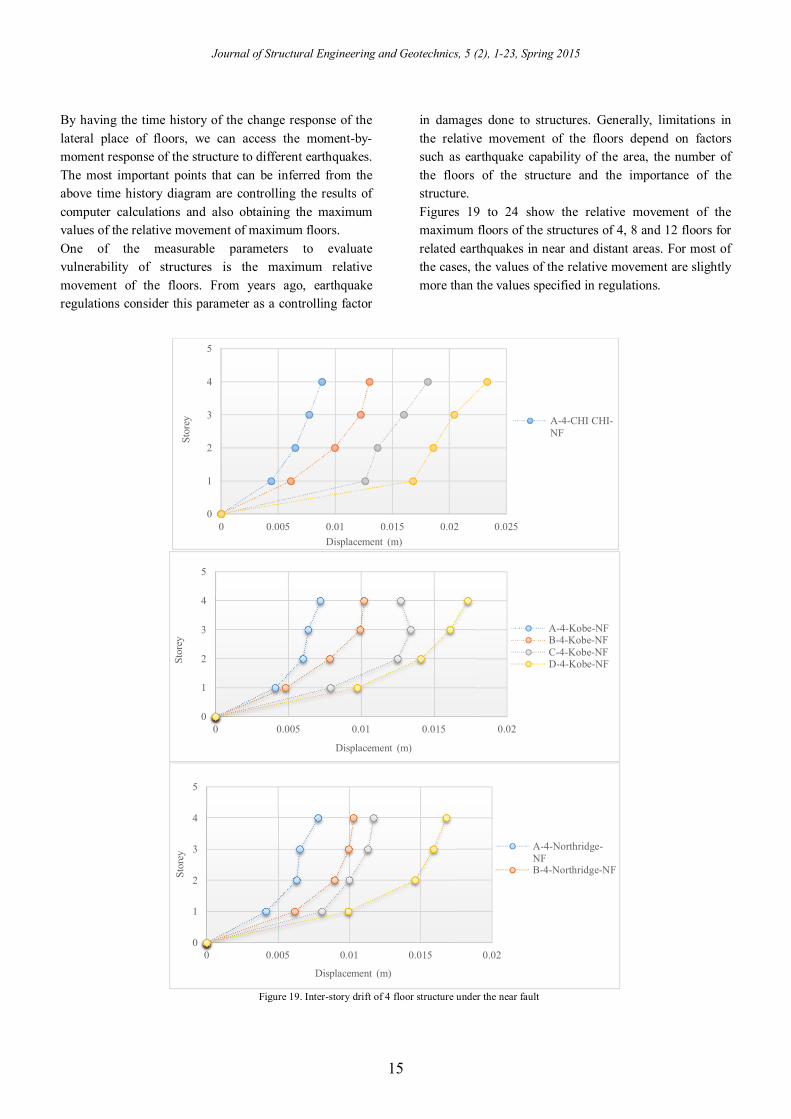
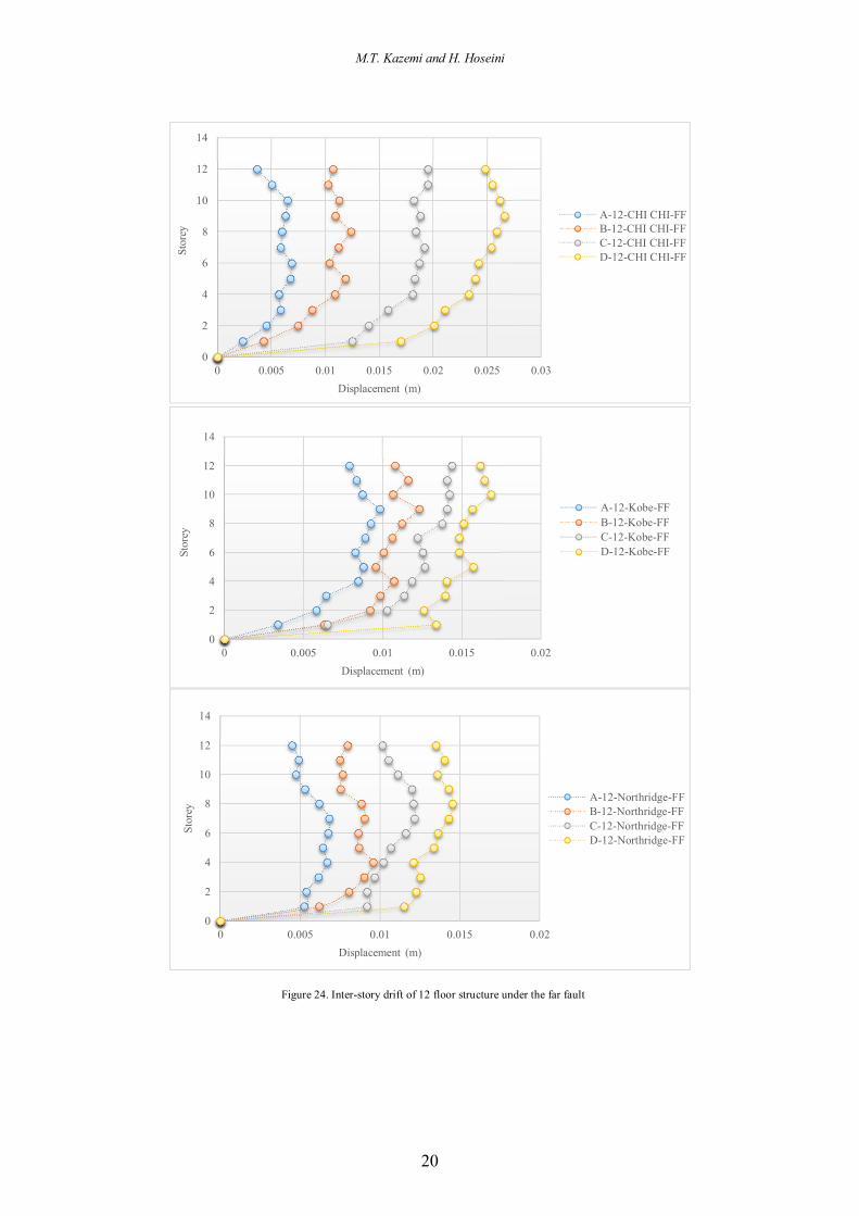
By having the time history of the change response of the lateral place of floors, we can access the moment-by-moment response of the structure to different earthquakes. The most important points that can be inferred from the above time history diagram are controlling the results of computer calculations and also obtaining the maximum values of the relative movement of maximum floors. One of the measurable parameters to evaluate vulnerability of structures is the maximum relative movement of the floors. From years ago, earthquake regulations consider this parameter as a controlling factor
in damages done to structures. Generally, limitations in the relative movement of the floors depend on factors such as earthquake capability of the area, the number of the floors of the structure and the importance of the structure. Figures 19 to 24 show the relative movement of the maximum floors of the structures of 4, 8 and 12 floors for related earthquakes in near and distant areas. For most of the cases, the values of the relative movement are slightly more than the values specified in regulations.
Figure 19. Inter-story drift of 4 floor structure under the near fault
0
1
2
3
4
5
0 0.005 0.01 0.015 0.02 0.025
Stor
ey
Displacement (m)
A-4-CHI CHI-NF
0
1
2
3
4
5
0 0.005 0.01 0.015 0.02
Stor
ey
Displacement (m)
A-4-Kobe-NFB-4-Kobe-NFC-4-Kobe-NFD-4-Kobe-NF
0
1
2
3
4
5
0 0.005 0.01 0.015 0.02
Stor
ey
Displacement (m)
A-4-Northridge-NFB-4-Northridge-NF

M.T. Kazemi and H. Hoseini
16
Figure 20. Inter-story drift of 4 floor structure under the far fault
0
1
2
3
4
5
0 0.005 0.01 0.015 0.02 0.025
Stor
ey
Displacement (m)
A-4-CHI CHI-FFB-4-CHI CHI-FFC-4-CHI CHI-FFD-4-CHI CHI-FF
0
1
2
3
4
5
0 0.005 0.01 0.015 0.02
Stor
ey
Displacement (m)
A-4-Kobe-FFB-4-Kobe-FFC-4-Kobe-FFD-4-Kobe-FF
0
1
2
3
4
5
0 0.002 0.004 0.006 0.008 0.01 0.012 0.014
Stor
ey
Displacement (m)
A-4-Northridge-FFB-4-Northridge-FFC-4-Northridge-FFD-4-Northridge-FF

Journal of Structural Engineering and Geotechnics, 5 (2), 1-23, Spring 2015
17
Figure 21. Inter-story drift of 8 floor structure under the near fault
0
1
2
3
4
5
6
7
8
9
0 0.005 0.01 0.015 0.02 0.025 0.03
Stor
ey
Displacement (m)
A-8-CHI CHI-NFB-8-CHI CHI-NFC-8-CHI CHI-NFD-8-CHI CHI-NF
0
1
2
3
4
5
6
7
8
9
0 0.005 0.01 0.015 0.02 0.025
Stor
ey
Displacement (m)
A-8-Kobe-NFB-8-Kobe-NFC-8-Kobe-NFD-8-Kobe-NF
0
1
2
3
4
5
6
7
8
9
0 0.005 0.01 0.015 0.02
Stor
ey
Displacement (m)
A-8-Northridge-NFB-8-Northridge-NFC-8-Northridge-NFD-8-Northridge-NF

M.T. Kazemi and H. Hoseini
18
Figure 22. Inter-story drift of 8 floor structure under the far fault
0
1
2
3
4
5
6
7
8
9
0 0.005 0.01 0.015 0.02 0.025
Stor
ey
Displacement (m)
A-8-CHI CHI-FFB-8-CHI CHI-FFC-8-CHI CHI-FFD-8-CHI CHI-FF
0
1
2
3
4
5
6
7
8
9
0 0.005 0.01 0.015 0.02
Stor
ey
Displacement (m)
A-8-Kobe-FFB-8-Kobe-FFC-8-Kobe-FFD-8-Kobe-FF
0
1
2
3
4
5
6
7
8
9
0 0.005 0.01 0.015 0.02
Stor
ey
Displacement (m)
A-8-Northridge-FFB-8-Northridge-FFC-8-Northridge-FFD-8-Northridge-FF

Journal of Structural Engineering and Geotechnics, 5 (2), 1-23, Spring 2015
19
Figure 23. Inter-story drift of 12 floor structure under the near fault
0
2
4
6
8
10
12
14
0 0.005 0.01 0.015 0.02 0.025 0.03
Stor
ey
Displacement (m)
A-12-CHI CHI-NFB-12-CHI CHI-NFC-12-CHI CHI-NFD-12-CHI CHI-NF
0
2
4
6
8
10
12
14
0 0.005 0.01 0.015 0.02 0.025
Stor
ey
Displacement (m)
A-12-Kobe-NFB-12-Kobe-NFC-12-Kobe-NFD-12-Kobe-NF
0
2
4
6
8
10
12
14
0 0.005 0.01 0.015 0.02
Stor
ey
Displacement (m)
A-12-Northridge-NFB-12-Northridge-NFC-12-Northridge-NFD-12-Northridge-NF
M.T. Kazemi and H. Hoseini
20
Figure 24. Inter-story drift of 12 floor structure under the far fault
0
2
4
6
8
10
12
14
0 0.005 0.01 0.015 0.02 0.025 0.03
Stor
ey
Displacement (m)
A-12-CHI CHI-FFB-12-CHI CHI-FFC-12-CHI CHI-FFD-12-CHI CHI-FF
0
2
4
6
8
10
12
14
0 0.005 0.01 0.015 0.02
Stor
ey
Displacement (m)
A-12-Kobe-FFB-12-Kobe-FFC-12-Kobe-FFD-12-Kobe-FF
0
2
4
6
8
10
12
14
0 0.005 0.01 0.015 0.02
Stor
ey
Displacement (m)
A-12-Northridge-FFB-12-Northridge-FFC-12-Northridge-FFD-12-Northridge-FF
Journal of Structural Engineering and Geotechnics, 5 (2), 1-23, Spring 2015
21
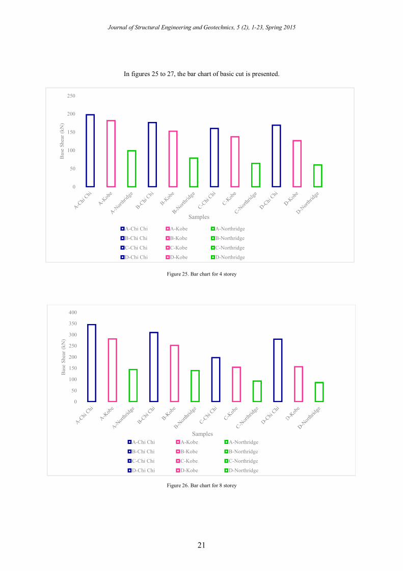
In figures 25 to 27, the bar chart of basic cut is presented.
Figure 25. Bar chart for 4 storey
Figure 26. Bar chart for 8 storey
0
50
100
150
200
250
Bas
e Sh
ear (
kN)
Samples
A-Chi Chi A-Kobe A-Northridge
B-Chi Chi B-Kobe B-Northridge
C-Chi Chi C-Kobe C-Northridge
D-Chi Chi D-Kobe D-Northridge
0
50
100
150
200
250
300
350
400
Bas
e Sh
ear (
kN)
SamplesA-Chi Chi A-Kobe A-Northridge
B-Chi Chi B-Kobe B-Northridge
C-Chi Chi C-Kobe C-Northridge
D-Chi Chi D-Kobe D-Northridge

M.T. Kazemi and H. Hoseini
22
Figure 27. Bar chart for 12 storey
7. Conclusion
In this study, two types of systems related to waste of inactive energy, i.e. frictional damper which is categorized in dampers dependent on movement and viscoelastic damper which is categorized in dampers dependent on velocity, in making steel structures resistant are investigated and evaluated. The advantages and disadvantages of these systems are described by studying four types of structural models. The analyses were conducted via nonlinear time history technique and by using earthquake records scaled with peak acceleration and SAP 2000 14.2.2 software. Finally, the results obtained from the structures with frictional damper have been compared with the results obtained from the structures with viscoelastic damper and structures with a combined system (viscoelastic and frictional). The results of the present study are as follows: The results indicate the appropriate function of the
selected dampers in controlling and decreasing the seismic responses of the structure. Given that in frictional dampers the maximum force created in the damper is specified, the use of this damper in resistance building of structures is very effective especially by considering the limitation of structure capacity.
The results indicate that when the height of the structure increases, the function of the dampers decreases. But the frictional damper has a better function compared to viscoelastic damper with regard to height.
Considering basic cut diagrams and the relative movement of the studied floors of the structure by the frictional damper and since more energy is absorbed in this structure compared to the structured made
resistant with viscoelastic damper and the structure without any damper, sections used in the structure with frictional damper are lighter than the other systems used.
Since frictional damper has more rigidity and energy absorption power than viscoelastic damper, the designer can take advantage of using lighter section in the design of bars and columns of the structure. This issue has been considered in the present study. Due to the use of lighter sections in frames equipped with frictional damper and the combination of these sections with this type of damper, we see more movements in floors compared to frames equipped with viscoelastic dampers. Of course these movements are in the allowed range due to the period of the structures with four, eight and twelve floors.
Also, frames equipped with frictional dampers have more plasticity compared to other systems and hence less basic cut. Of course the content of the frequency of Kobe, Northridge and Chi Chi is effective in alterations of basic cut force.
The combination of frictional and viscoelastic dampers creates a combination of the rigidities of these two types of dampers in the structure and the designer can reach his intended rigidity and plasticity in the design of the structure by combining the two types of dampers and have more options in the design and more control over decreasing the structure's responses, increasing the rigidity or plasticity, controlling the maximum movement of the floors, basic cut and floors' cut depending on the height and period of the structure.
0
100
200
300
400
500
600
Bas
e Sh
ear (
kN)
SamplesA-Chi Chi A-Kobe A-NorthridgeB-Chi Chi B-Kobe B-NorthridgeC-Chi Chi C-Kobe C-NorthridgeD-Chi Chi D-Kobe D-Northridge

Journal of Structural Engineering and Geotechnics, 5 (2), 1-23, Spring 2015
23
When the height, period and mass of the structure increases, the seismic resistant system needs to have the required rigidity and plasticity to keep the relative
movement of the maximum floors in the allowed range and control the basic cut of the structure. Given these conditions, the use of frictional damper in more height seems more appropriate.
Considering the brace in both openings of the plan of the present study creates more relative rigidity for the system and this in turn can be one of the reasons for less relative movement of the floors and more basic cut of the system compared to the moods that we have dampers.
In four-floor structure the relative movement of the maximum floors in the area close to fault is more than the areas far from the fault in 90 percent of the times.
In height- and twelve-floor structures the relative movement of the maximum floors in the area close to fault is more than the areas far from the fault in all of the conditions.
The effect of the combined system of frictional and viscoelastic dampers in decreasing seismic response and the relative movement of the maximum floors in the area close to fault and the areas that are far from the fault is nearly the same.
8. References [1] Lee, KS., Fan, CP., Sause, R., Ricles, J. (2005). Simplified
design procedure for frame buildings with viscoelastic or elastomeric structural dampers. Earthquake Engineering & Structural Dynamic Journal. 34(10):1271–1284.
[2] Symans, MD., Charney, FA., Whittaker, AS., Constantinou, MC., Kircher, CA., Johnson, MW., McNamara, RJ. (2008). Energy dissipation systems for seismic applications: current practice and recent developments. Journal Structural Engineering (ASCE). 134(1):3–21.
[3] Lee, SH., Park, JH., Lee, SK., Min, KW. (2008). Allocation and slip load of friction dampers for a seismically excited building structure based on storey shear force distribution. Engineering Structures, 30,930–40.
[4] Min, Kyung-Won., Seong, Ji-Young., Kim, Jinkoo. (2010). Simple design procedure of a friction damper for reducing seismic responses of a single-story structure. Engineering Structures, 32:3539–47.
[5] Martínez Rodrigo, MD., Lavado, J., Museros, P. (2010). Dynamic performance of existing high-speed railway bridges under resonant conditions retrofitted with fluid viscous dampers. Engineering Structures. 32(3):808–828.
[6] Mazza, F., Vulcano, A. (2011). Control of the earthquake and wind dynamic response of steel-framed buildings by using additional braces and/or viscoelastic dampers. Earthquake Engineering & Structural Dynamic Journal. 40(2):155–174.
[7] Petti, L., De, Iuliis, M. (2008). Torsional seismic response control of asymmetric-plan systems by using viscous dampers. Engineering Structures. 30(11):3377–3388.
[8] Min, Won-Kyung., Seong, Ji-Young., Kim, Jinkoo., (2010). Simple design procedure of a friction damper for reducing seismic responses of a single-storey structure. Enginnering Structures, 32 (11), 3539-3547.
[9] Mirtaheri, Masoud., Zandi, Amir Peyman., Sharifi Samadi, Sahand., Rahimi Samani, Hamid., (2011). Numerical and experimental study of hysteretic behavior of cylindrical friction dampers. Enginnering Structures, 33 (12), 3647-3656.
[10] Mirzabagheri, M., Sanati, M., Aghakouchak, A. A., Khadem, S, E., (2015), Numerical and experimental investigated of rotational friction dampers with multi units in steel frames subjected to lateral excitation. Archives of civil and mechanical engineering, 15 (12), 479-491.
[11] Rijnen, M. W. L. M., Pasteuning, F., Fey, R.H.B., Van Schothorst, G. (2015). A numerical and experimental study on viscoelastic damping of a 3D structure. Journal of Sound and Vibration, 349, 80-98.
[12] Ywan-LU, Lyan., Lin, Ging-Long., Shih, Ming-Hsiang. (2012). An experimental study on a generalized Maxwell model for nonlinear viscoelastic dampers used in seismic isolation. Enginnering Structures, 34, 111-123.
[13] Karavasilis, Theodore L., Blackeborou, Ton., Willams, Martin., (2011). Development of nonlinear analytical model and seismic analyses of a steel frame with self-centering devices and viscoelastic dampers. Computers and Structures, 89 (11-12), 1232-1240.
[14] LewandowskIi, R., Bartkowiak, A., Maciejewski, H. (2012). Dynamic analysis of frames with viscoelastic dampers: a comparison of damper models. Structural Engineering and Mechanics. 41(1), 113-137.
[15] Vasghi Amiri, J., Naghipoor, M., Jalali, S. G. (2008). Performance of rotational friction damper (RFD) in steel frames. The 14th World Conference on Earthquake Engineering October 12-17, 2008, Beijing, China.
[16] Standard no.2800. (2004). Iranian code of practice for seismic resistant design of buildings. 3rd edition. Building and Housing Research Center.
[17] PEER Strong Motion Database. (2015) .pacific earthquake engineering research center. http://peer.berkeley.edu.
[18] CSI. SAP2000. 14.2.2 ed. Computers and Structures, Inc.; 2009.