PERFORMANCE EVALUATION OF THE GPS BLOCK IIR TIME …
14
PERFORMANCE EVALUATION OF THE GPS BLOCK IIR TIME KEEPING SYSTEM Andy Wu The Aerospace Corporation 4452 Canoga Drive, Woodland Hills, California 91364, USA (310) 336-0437 (telephone), (310) 336-5076 (fax) [email protected] Abstract The Time Keeping System (TKS) is asenhhl to the GPS Block IIR totcrl navigation palload and must provide an crccura!e tinu tmse for each GPS space vehicle. Pcrfonnance ~ 4 1 y s i s of the TKS has been reported previously for the m e in which a rubidium [Rb) atomic frequency standard is used as a reference. In this paper the system error model of the TKS is developed and the perjonnance of the TKS output using either a cesium (Cs) or a rubidium (Rb) atomic frequency shuhrds as a reference is evaluated. The contributions to the TKS output AUM deviation was examined from mch of the three noise sources: olomicfnquency standard (either Cs or Rb), vokge control crystal oscillator (VCXO), and phase mier (PM). In addition, since the TKS does not have a baseplate temperature controller and thr VCXO of the TKS is tempmature-sensitive, a TKS m o r is induced when the VCXO is xubjcd to the orbital tempemlure v - or the space vehicle umbra during solar eclipse. These two temperature-induced TKS output mars are also rxcuninod. Sensitivities of the Allan v a ~ n c e at the TKS output for each of its indrpcndmt input noises are provided and they are valuable for design trade-off and troub*shdng. The resuUs of this paper compare favombly with those obtained by the TKS system W i n g . 'RK paper will show that when the TKS components m& or meed their sped&- the RlFS TKS and the CAPS TKS should meet their specifications. I 1 INTRODUCTION The GPS Block IIR Time Keeping System (TKS) is used to generate a system output frequency of 10.23 MHz from an Atomic Frequency Standard (AFS) as an input reference. The output frequency of either the Cs AFS (CAFS) or the Rb AFS (RAFS) is approximately 13.4 MHz. L Dither frequency for the Selective Availability (SA), if enabled, is added to the TKS output. t The block diagram of the TKS system model is shown in Figure 1. Both CAFS and RAFS as frequency references to the TKS are considered in this paper and are referred as the CAFS TKS and the RAFS TKS respectively. A reference epoch is generated every 15 s based on the AFS frequency and another 1.5 s interval system epoch is generated by the 10.23 MHz system clock of the VCXO. Both epochs are input to the Phase Meter (PM), and the PM computes the timing error between the two epochs in terms of number of cycles of an asynchronous 600 MHz clock. Considering the timing error value, the loop adjusts the phase of the epoch from the VCXO so that the VCXO is phase-locked to the reference AFS. In this paper the system error model of the TKS is developed and the performance of the TKS frequency output is evaluated from each of the three noise sources: atomic frequency
Transcript of PERFORMANCE EVALUATION OF THE GPS BLOCK IIR TIME …

PERFORMANCE EVALUATION OF THE GPS BLOCK IIR TIME KEEPING SYSTEM
Andy Wu The Aerospace Corporation
4452 Canoga Drive, Woodland Hills, California 91364, USA (310) 336-0437 (telephone), (310) 336-5076 (fax)
Abstract
The Time Keeping System (TKS) is asenhhl to the GPS Block IIR totcrl navigation palload and must provide an crccura!e tinu tmse for each GPS space vehicle. Pcrfonnance ~ 4 1 y s i s of the TKS has been reported previously for the m e in which a rubidium [Rb) atomic frequency standard is used as a reference. In this paper the system error model of the TKS is developed and the perjonnance of the TKS output using either a cesium (Cs) or a rubidium (Rb) atomic frequency shuhrds as a reference is evaluated. The contributions to the TKS output AUM deviation was examined from mch of the three noise sources: olomicfnquency standard (either Cs or Rb), vokge control crystal oscillator (VCXO), and phase mier (PM). In addition, since the TKS does not have a baseplate temperature controller and thr VCXO of the TKS is tempmature-sensitive, a TKS m o r is induced when the VCXO is xubjcd to the orbital tempemlure v- or the space vehicle umbra during solar eclipse. These two temperature-induced TKS output mars are also rxcuninod. Sensitivities of the Allan v a ~ n c e at the TKS output for each of its indrpcndmt input noises are provided and they are valuable for design trade-off and troub*shdng. The resuUs of this paper compare favombly with those obtained by the TKS system Wing . 'RK paper will show that when the TKS components m& or meed their sped&- the RlFS TKS and the CAPS TKS should meet their specifications.
I 1 INTRODUCTION
The GPS Block IIR Time Keeping System (TKS) is used to generate a system output frequency of 10.23 MHz from an Atomic Frequency Standard (AFS) as an input reference. The output frequency of either the Cs AFS (CAFS) or the Rb AFS (RAFS) is approximately 13.4 MHz.
L Dither frequency for the Selective Availability (SA), if enabled, is added to the TKS output.
t The block diagram of the TKS system model is shown in Figure 1. Both CAFS and RAFS as frequency references to the TKS are considered in this paper and are referred as the CAFS TKS and the RAFS TKS respectively. A reference epoch is generated every 15 s based on the AFS frequency and another 1.5 s interval system epoch is generated by the 10.23 MHz system clock of the VCXO. Both epochs are input to the Phase Meter (PM), and the PM computes the timing error between the two epochs in terms of number of cycles of an asynchronous 600 MHz clock. Considering the timing error value, the loop adjusts the phase of the epoch from the VCXO so that the VCXO is phase-locked to the reference AFS.
In this paper the system error model of the TKS is developed and the performance of the TKS frequency output is evaluated from each of the three noise sources: atomic frequency
Report Documentation Page Form ApprovedOMB No. 0704-0188
Public reporting burden for the collection of information is estimated to average 1 hour per response, including the time for reviewing instructions, searching existing data sources, gathering andmaintaining the data needed, and completing and reviewing the collection of information. Send comments regarding this burden estimate or any other aspect of this collection of information,including suggestions for reducing this burden, to Washington Headquarters Services, Directorate for Information Operations and Reports, 1215 Jefferson Davis Highway, Suite 1204, ArlingtonVA 22202-4302. Respondents should be aware that notwithstanding any other provision of law, no person shall be subject to a penalty for failing to comply with a collection of information if itdoes not display a currently valid OMB control number.
1. REPORT DATE DEC 1996 2. REPORT TYPE
3. DATES COVERED 00-00-1996 to 00-00-1996
4. TITLE AND SUBTITLE Performance Evaluation of the GPS Block IIR Time Keeping System
5a. CONTRACT NUMBER
5b. GRANT NUMBER
5c. PROGRAM ELEMENT NUMBER
6. AUTHOR(S) 5d. PROJECT NUMBER
5e. TASK NUMBER
5f. WORK UNIT NUMBER
7. PERFORMING ORGANIZATION NAME(S) AND ADDRESS(ES) The Aerospace Corporation,4452 Canoga Drive,Woodland Hills,CA,91364
8. PERFORMING ORGANIZATIONREPORT NUMBER
9. SPONSORING/MONITORING AGENCY NAME(S) AND ADDRESS(ES) 10. SPONSOR/MONITOR’S ACRONYM(S)
11. SPONSOR/MONITOR’S REPORT NUMBER(S)
12. DISTRIBUTION/AVAILABILITY STATEMENT Approved for public release; distribution unlimited
13. SUPPLEMENTARY NOTES See also ADA419480. 28th Annual Precise Time and Time Interval (PTTI) Applications and PlanningMeeting, Reston, VA, 3-5 Dec 1996
14. ABSTRACT see report
15. SUBJECT TERMS
16. SECURITY CLASSIFICATION OF: 17. LIMITATION OF ABSTRACT Same as
Report (SAR)
18. NUMBEROF PAGES
13
19a. NAME OFRESPONSIBLE PERSON
a. REPORT unclassified
b. ABSTRACT unclassified
c. THIS PAGE unclassified
Standard Form 298 (Rev. 8-98) Prescribed by ANSI Std Z39-18

standard (either Cs or Rb), voltage control crystal oscillator (VCXO), and phase meter (PM). In addition, since the VCXO is temperature-sensitive and the TKS does not have a baseplate temperature controller, the TKS error induced by the VCXO is also computed when the VCXO is subject to the orbital temperature variations or the space vehicle umbra during solar eclipse. The other intent of this paper is to provide as much relevant technical information as possible to the users of the GPS Block IIR Time Keeping System.
2 GPS TKS STABILITY REQUIREMENTS
The TKS stability requirements for the GPS Block IIAIA, Block IIR, and Block IIF using either a Rb AFS or a Cs AFS as an input reference is shown in Figure 2. It is interesting to note that the Allan deviation requirement of the Block IUIIA CFS TKS has a slope of T - O . ~ '
instead of the theoretical value of Also, the Block IIF TKS requirement is better than that of the Block IIR CAFS TKS and is not as good as that of the Block IIR RAFS TKS.
3 TKS BASIC NOISE MODELS 3.1 Phase Meter Phase Noise
The TKS phase meter noise was derived in [I] and it is shown to be a white phase noise. The power spectral density and the Allan variance are
where T, is a cycle period of the 600 MHz clock.
3.2 VCXO Frequency Noise
The VCXO frequency noise is characterized by the following Allan variancew:
aay(7) = lo-" + 1 0 - ~ 7 . (2) r]
Assuming that the two terms of Eq. (2) are independent of each other, the power spectral f
density of the VCXO intrinsic frequency noise can expressed asM:
3.3 AFS Frequency Noise
The Allan variances for both the CAFS and the RAFS are specified in [2,4].
u ~ ~ ( T ) = 9.0 x I O - ~ / T + 1.0 x 10-",for the CAFS noise
dR(7) = 1.0 x ~ O - ~ ~ / T + 2.5 x 10-~,for the RAFS noise
The associated noise power spectral densities can be computed using well-known techniquesbl:
&(T) = 1.8 x + 7.213 x f , for the CAFS noise
(5)
d R ( r ) = 2.0 x lo-" + 1.803 x f , for the RAFS noise
The Allan deviations of the PM phase noise, the VCXO frequency noise, the CAFS frequency noise, and the RAFS frequency noise are shown in Figure 3. Note that the PM phase noise is governing for low T and the VCXO frequency noise is dominant for the T > 60 s.
L 4 TKS TRANSFER FUNCTIONS
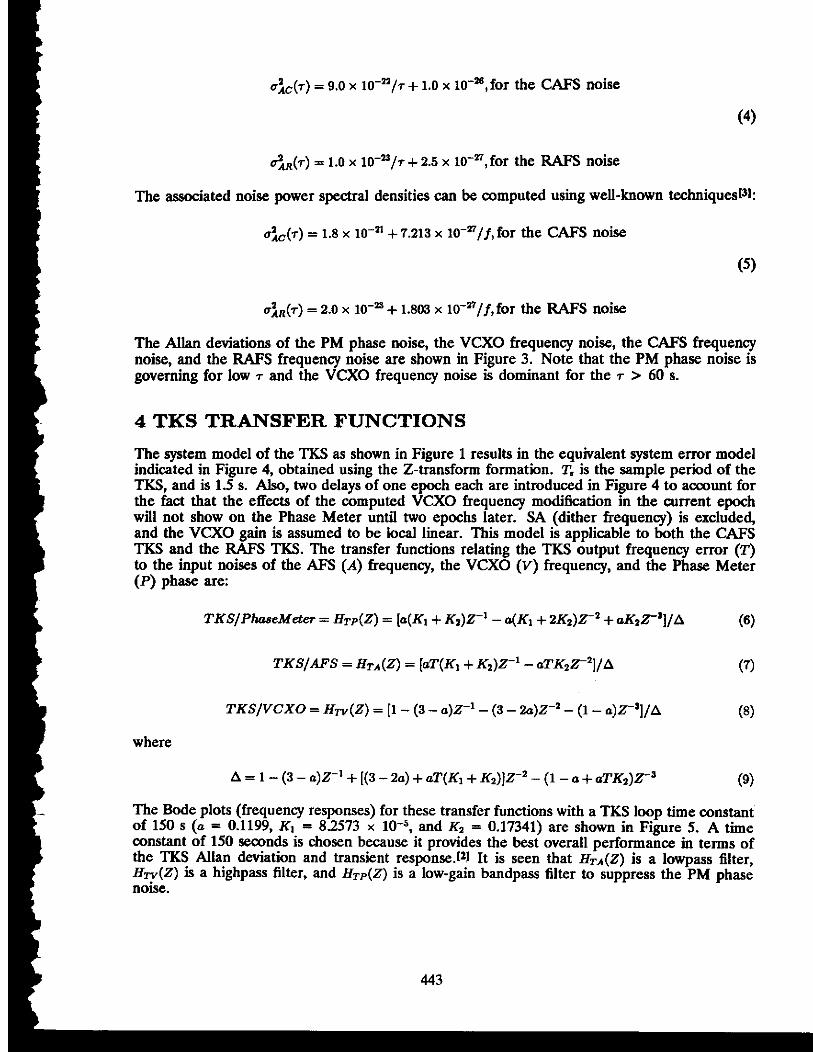
I The system model of the TKS as shown in Figure 1 results in the equivalent system error model indicated in Figure 4, obtained using the Z-transform formation. T, is the sample period of the TKS, and is 1.5 s. Also, two delays of one epoch each are introduced in Figure 4 to account for
1 the fact that the effects of the computed VCXO frequency modification in the current epoch will not show on the Phase Meter until two epochs later. SA (dither frequency) is excluded, and the VCXO gain is assumed to be local linear. This model is applicable to both the CAFS
I TKS and the RAFS TKS. The transfer functions relating the TKS output frequency error (T) to the input wises of the AFS (A) frequency, the VCXO (V) frequency, and the Phase Meter (P) phase are:
TKSIVCXO = HTv(Z) = [I - (3 - a ) ~ ' - (3 - 2 a ) ~ - ~ - (1 - ~)z-']/A i (8)
where
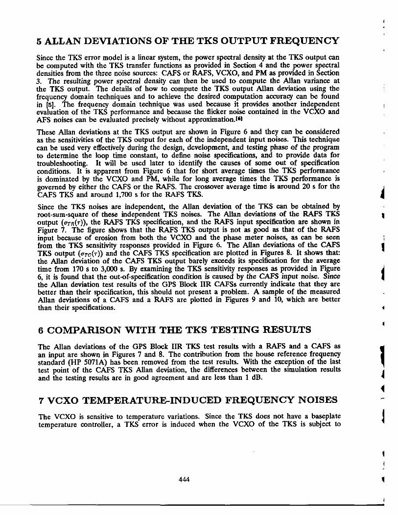
The Bode plots (frequency responses) for these transfer functions with a TKS loop time constant of 150 s (a = 0.1199, KI. = 8.2573 x lo4, and K2 = 0.17341) are shown in Figure 5. A time constant of 150 seconds 1s chosen because it provides the best overall performance in terms of the TKS Allan deviation and transient response.['] It is seen that HTA(Z) is a lowpass filter, Hw(Z) is a highpass filter, and HTP(Z) is a low-gain bandpass filter to suppress the PM phase noise.
5 ALLAN DEVIATIONS OF THE TKS OUTPUT FREQUENCY
Since the TKS error model is a linear system, the power spectral density at the TKS output can be computed with the TKS transfer functions as provided in Section 4 and the power spectral densities from the three noise sources: CAFS or RAFS, VCXO, and PM as provided in Section 3. The resulting power spectral density can then be used to compute the Allan variance at the TKS output. The details of how to compute the TKS output Allan deviation using the frequency domain techniques and to achieve the desired computation accuracy can be found in Is]. The frequency domain technique was used because it provides another independent evaluation of the TKS performance and because the flicker noise contained in the VCXO and AFS noises can be evaluated precisely without approximation.16l
These Allan deviations at the TKS output are shown in Figure 6 and they can be considered as the sensitivities of the TKS output for each of the independent input noises. This technique can be used very effectively during the design, development, and testing phase of the program to determine the loop time constant, to define noise specifications, and to provide data for troubleshooting. It will be used later to identify the causes of some out of specification conditions. It is apparent from Figure 6 that for short average times the TKS performance is dominated by the VCXO and PM, while for long average times the TKS performance is governed by either the CAFS or the RAFS. The crossover average time is around 20 s for the CAFS TKS and around 1,700 s for the RAFS TKS.
Since the TKS noises are independent, the Allan deviation of the TKS can be obtained by root-sum-square of these independent TKS noises. The Allan deviations of the RAFS TKS output (oTn(7)), the RAFS TKS specification, and the RAFS input specification are shown in Figure 7. The figure shows that the RAFS TKS output is not as good as that of the RAFS input because of erosion from both the VCXO and the phase meter noises, as can be seen from the TKS sensitivity responses provided in Figure 6. The M a n deviations of the CAFS TKS output ( ~ ~ ~ ( 7 ) ) and the CAFS TKS specification are plotted in Figures 8. It shows that: the Allan deviation of the CAFS TKS output barely exceeds its specification for the average time from 170 s to 3,000 s. By examining the TKS sensitivity responses as provided in Figure 6, it is found that the out-of-specification condition is caused by the CAFS input noise. Since the Allan deviation test results of the GPS Block IIR CAFSs currently indicate that they are better than their specification, this should not present a problem. A sample of the measured Allan deviations of a CAFS and a RAFS are plotted in Figures 9 and 10, which are better than their specifications.
6 COMPARISON WITH THE TKS TESTING RESULTS
The Allan deviations of the GPS Block IIR TKS test results with a RAFS and a CAFS as an input are shown in Figures 7 and 8. The contribution from the house reference frequency standard (HP 5071A) has been removed from the test results. With the exception of the last test point of the CAFS TKS Allan deviation, the differences between the simulation results and the testing results are in good agreement and are less than 1 dB.
7 VCXO TEMPERATUREINDUCED FREQUENCY NOISES
The VCXO is sensitive to temperature variations. Since the TKS does not have a baseplate temperature controller, a TKS error is induced when the VCXO of the TKS is subject to

the orbital temperature variations or the space vehicle umbra during solar eclipse. These two temperature-induced TKS output errors are examined below.
7.1 TKS Error Due to the Orbital Temperature Variations
When the VCXO is subject to an orbital temperature variation estimated to be it 2 5 degrees maximum with a period of 12 hours, the VCXO temperature-induced frequency noise with a temperature coefficient specification of 4 x lo-" (df1f)PC can be descriied as:
I where f. = 1/(12 x 3,600) is the orbital frequency with a period of 12 hours and 0 is an arbitrary starting phase angle. This TKS input frequency error with 0 = 90 degrees is plotted in Figure 11. The TKS output frequency error due to this VCXO input frequency noise can be computed using the transfer function of HTV(Z) and the result is provided in Figure 12.
I It is 180 degrees out of phase from the input frequency noise, as confirmed by the VCXO phase angle plot of the Bode diagram of Figure 5. The resulting TKS output timing error can be obtained by integrating the output frequency error and is shown in Figure 13. The Allan deviation of this timing error is computed using the overlapping samples technique and is shown in Figure 14. As can be seen, it is below the RAFS TICS specification line.
The TKS Allan deviation induced by orbital VCXO effect can also be determined analytically.
t The TKS loop gain from the VCXO to the TKS output at the orbital period of 12 hours can be obtained from its Bode plot, as shown in Figure 5 or can be determined by
= 3.84 x lo-'. I
1 Since the TKS error model is a linear system, the frequency error at the TKS output can be obtained as

This is in perfect agreement with that shown in Figure 12 with @ = 90 degrees. The TKS output Allan van'ance from this sine frequency can be determined to be
The square root of this Allan variance is shown in Figure 14 and clearly agrees with that obtained early by simulation.
7.2 TKS Error Due to the Space Vehicle Umbra During Solar Eclipse
The temperature profile due to the space vehicle umbra can be modeled as a 2 degreeshour shift for a 112 hour and then a settling at a constant temperature for l/2 hour before sloping back to its original temperature.Pl The resulting VCXO frequency error at the TKS input with a temperature coefficient of 4 x lo-" (df/f)PC is shown in Figure 11. The TKS output frequency error due to this VCXO input frequency noise can be computed using the transfer function of H r v ( Z ) and the result is provided in Figure 12. The resulting TKS output timing error is provided in Figure 13. The Allan deviation of this umbra error can be computed from this timing error and the result is shown in Figure 14. Again, this umbra-induced TKS error is below the RAFS specification line.
7.3 TKS Error Due to VCXO Out-of-Specification Temperature Coefficient
In the early delivery of the VCXOs, some of them have a temperature coefficient of 14 x lo-" (df/f)/"C, that is, about 3.5 times of the specification. The TKS Allan deviations due to this out of specification for both the orbital and umbra effects are recomputed and are shown in Figure (15); as expected, they are much closer to the RAFS specification line. The Allan deviation of the RAFS TKS with the out-of-specification VCXO is also shown in Figure 15, and it meets the RAFS TKS specification.
8 CONCLUSIONS
The contributions to the TKS output Allan deviation from the three basic TKS noises as well as the VCXO orbital and umbra temperature-induced noises were computed. These formed the sensitivities of the Allan deviation at the TKS output for each of its input noises and they are valuable for design trade-off and troubleshooting. The results of this paper compare favorably with those obtained from the TKS system testing. When the TKS components meet their specifications, the RAFS TKS should meet its specification. -The CAFS TKS should have no problem of meeting its specification, since the CAFS normally would exceed its specification.
9 REFERENCES
[I] J. Han 1993, "Perfomance analysis of clock stability for GPS Block IIR satel- lites, " ATM-93(3470-01)-5, The Aerospace Corporation, Woodland Hills, California, USA, 27 September 1993.
[2] H. Rawicz, M. Epstein, and J. Rajan 1993, "The Time Keeping System for GPS Block IZR," Proceedings of the 24th Annual Precise Time and Time Interval (PTTI)

Applications and Planning Meeting, 1-3 December 1992, McLean, Virginia, USA (NASA CP-3218), pp. 5-16.
[s] J. Barnes, et al. 1971, "Chamcterization of frequency stability, " IEEE Transac- tions on Instrumentation and Measurement, IM-20, pp. 105-120.
[4] A. Baker 1991, "GPS Block IIR time standard assembly architecturn, " Proceedings of the 22nd Annual Precise Time and Time Interval (F"rT1) Applications and Planning Meeting, 4-6 December 1990, Vienna, Virginia, USA (NASA CP-3116), pp. 317-324.
[5] A. Wu 1995, "Allan deviation computation of a linear frequency synthesizer system using frepuency domain techniques, " Proceedings of the 26th Annual Precise Time and Time Interval (PTTI) Applications and Planning Meeting, 6-8 December 1994, Reston, Virginia, USA (NASA CP-3302). pp. 393-404.
16) J.A. Barnes, and S. Jarvia, Jr. 1971, "Eficient numerical and analog modeling of flicker noise process," National Bureau of Standards Technical Note 604.
[?I H. O'Donnel1995, "E&t of VCXO temperature-induced ecrors, " Lockheed Martin Astro-Space Interoffice Memorandum to A. Das, 24 August 1995.

I Clock I ) Dither I
*tO.ir Frequency SUndard
(AFS)
13.4 MHz &lb~l.-J Figure 1. GPS Block UR TKS System Model
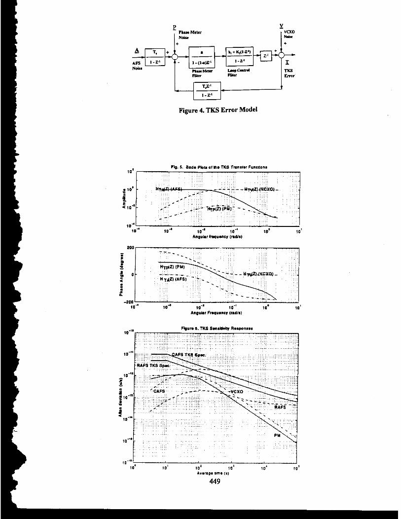
Figure 4. TKS Error Model
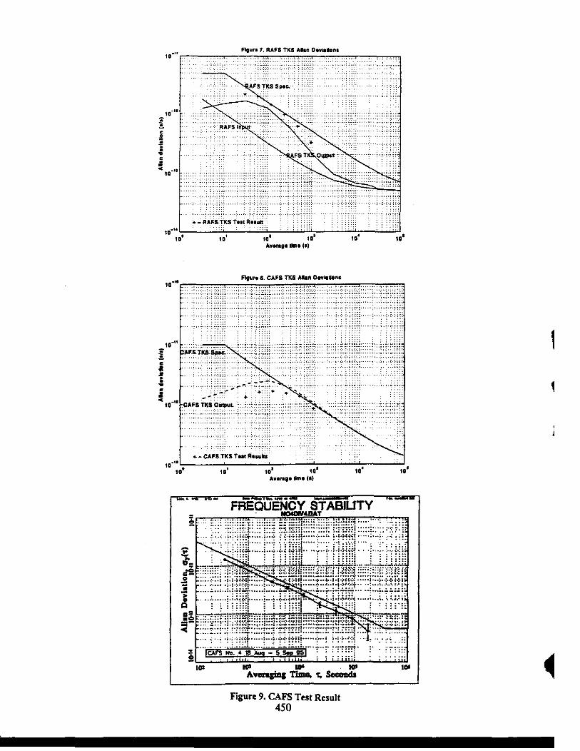
Figure 9. CAR5 Test Result 450

Figure 10. RAFS Test Result

Fburn 13. TIU Oumull inns Emr 0.5
Av.rngng Na. (I)
m u m 1s. RAFS TICS AIUD O.rhC+n. rh Out-ol-Sner. VCXO
Questions and Answers STEVEN HUTSELL (USNO): There's an earlier plot that at least seems to indicate - and I'd like your opinion - that possibly with some manipulation of the gains, the servo could take better advantage of the physics package stability. I'd like your comment on that.
ANDY WU: The reason that 150 seconds was chosen was because the phase meter is so poor, having a resolution of 1.67 nanoseconds. So you need a long time constant to smooth it out. I did try one - let's say 12 or 15 seconds. And you're going to see the phase meter is going to pop over out here and you're going to have a problem.