

Performance Evaluation Of BPSK And QPSK Modulation … · Performance Evaluation Of BPSK And QPSK...
5
Performance Evaluation Of BPSK And QPSK Modulation With LDPC Codes B. B. Badhiye Dr. S. S. Limaye Associate Professor, Deptt. Of Electronics Engg. Professor and Principal , Deptt. Of Electronics Engg. M.I.E.T.,Gondia ,(M.S.), India J.I.T.,Nagpur,(m.s.), India Abstract : BPSK and QPSK are the digital modulation schemes, QPSK and further/ QPSK are the best suited modulation techniques therefore more emphasize given on QPSK, which specially used in DVB area. A coding and modulation technique is studied where the coded bits of an irregular LDPC are passed directly to a modulator. We evaluate and compare the bit error rate, signal constellations etc. In this paper, we consider a transmission over a Gaussian noise channel. Log Likelihood Ratio (LLR) decoder can be suggested for receiver. Index Terms: Differntial Quadrature Phase Shift Keying (DQPSK),Low Density Parity Check Codes(LDPC). 1. Introduction of BPSK/QOSK: The BPSK and QPSK system considered in this paper, illustrated in Figure(1), consists of a bit source, transmitter, channel, receiver, and a bit sink. The bit source generates a stream of information bits to be transmitted by the transmitter .typically, a random bit generator is employed as a bit source in simulations and this is the case herein as well. The transmitter converts the bits into QPSK symbols and applies optional pulse shaping and up conversion. The output from the transmitter is fed through a channel, which in its simplest form is an AWGN channel. The receiver block takes the output from the channel, estimates timing and phase offset, and demodulates the received QPSK symbols into information bits, which are fed to the bit sink. Typically, in a simulation environment, the bit sink simply counts the number of errors that occurred to gather statistics used for investigating the performance of the system. Figure(1)The QPSK Communication System. 1. BPSK is a real-valued constellation with two signal points: c(0) = A and c(1) = -A, where A is a scaling factor. This is shown in Figure 2 (a). The average complex baseband symbol energy is E 8 = E[c(i) 2 ] = A 2 . 2. QPSK is a complex constellation with four signal points, c(i) = exp 2 + 1 2 , For I = 0, 1,2,3. It is convenient to include the 2 factor so that the average symbol energy is E s = E[||c(i)|| 2 ] = 2A 2 , double that of BPSK, but with the same energy per transmitted bit as BPSK.[1][2][3][8] 2 Basics of LDPC International Journal of Engineering Research & Technology (IJERT) Vol. 2 Issue 1, January- 2013 ISSN: 2278-0181 1 www.ijert.org
Transcript of Performance Evaluation Of BPSK And QPSK Modulation … · Performance Evaluation Of BPSK And QPSK...
Performance Evaluation Of BPSK And QPSK Modulation With LDPC Codes
B. B. Badhiye Dr. S. S. Limaye
Associate Professor, Deptt. Of Electronics Engg. Professor and Principal , Deptt. Of Electronics Engg.
M.I.E.T.,Gondia ,(M.S.), India J.I.T.,Nagpur,(m.s.), India
Abstract : BPSK and QPSK are the digital
modulation schemes, QPSK and further𝝅/
𝟒𝑫QPSK are the best suited modulation techniques
therefore more emphasize given on QPSK, which
specially used in DVB area. A coding and
modulation technique is studied where the coded
bits of an irregular LDPC are passed directly to a
modulator. We evaluate and compare the bit error
rate, signal constellations etc. In this paper, we
consider a transmission over a Gaussian noise
channel. Log Likelihood Ratio (LLR) decoder can
be suggested for receiver.
Index Terms: Differntial Quadrature Phase Shift
Keying (DQPSK),Low Density Parity Check
Codes(LDPC).
1. Introduction of BPSK/QOSK:
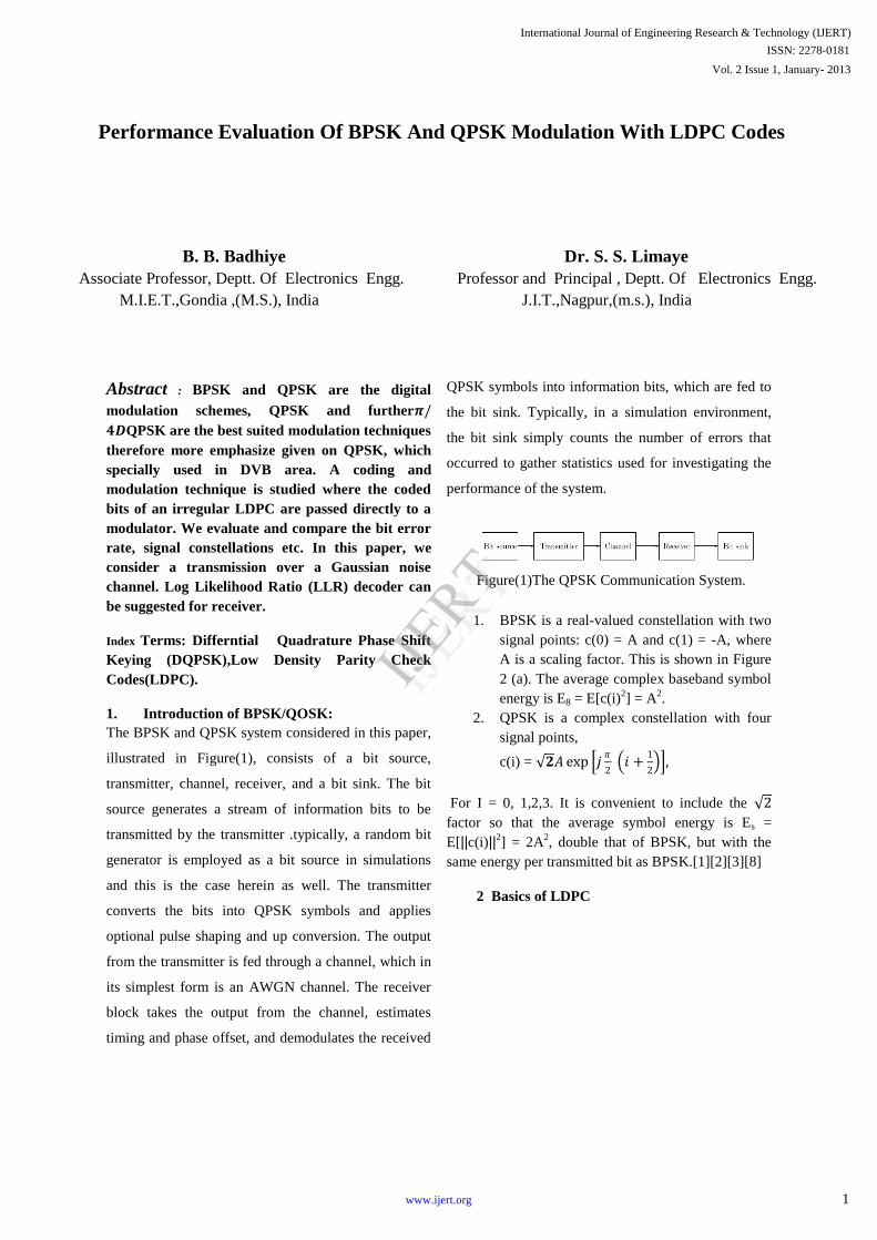
The BPSK and QPSK system considered in this paper,
illustrated in Figure(1), consists of a bit source,
transmitter, channel, receiver, and a bit sink. The bit
source generates a stream of information bits to be
transmitted by the transmitter .typically, a random bit
generator is employed as a bit source in simulations
and this is the case herein as well. The transmitter
converts the bits into QPSK symbols and applies
optional pulse shaping and up conversion. The output
from the transmitter is fed through a channel, which in
its simplest form is an AWGN channel. The receiver
block takes the output from the channel, estimates
timing and phase offset, and demodulates the received
QPSK symbols into information bits, which are fed to
the bit sink. Typically, in a simulation environment,
the bit sink simply counts the number of errors that
occurred to gather statistics used for investigating the
performance of the system.
Figure(1)The QPSK Communication System.
1. BPSK is a real-valued constellation with two
signal points: c(0) = A and c(1) = -A, where
A is a scaling factor. This is shown in Figure
2 (a). The average complex baseband symbol
energy is E8 = E[c(i)2] = A
2.
2. QPSK is a complex constellation with four
signal points,
c(i) = 𝟐𝐴 exp 𝑗𝜋
2 𝑖 +
1
2 ,
For I = 0, 1,2,3. It is convenient to include the 2
factor so that the average symbol energy is Es =
E[||c(i)||2] = 2A2, double that of BPSK, but with the
same energy per transmitted bit as BPSK.[1][2][3][8]
2 Basics of LDPC
International Journal of Engineering Research & Technology (IJERT)
Vol. 2 Issue 1, January- 2013
ISSN: 2278-0181
1www.ijert.org
IJERT
IJERT
.
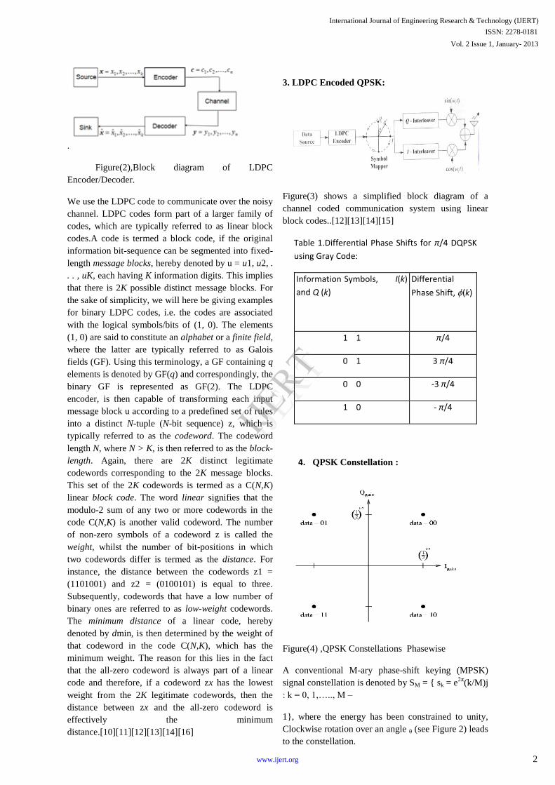
Figure(2),Block diagram of LDPC
Encoder/Decoder.
We use the LDPC code to communicate over the noisy
channel. LDPC codes form part of a larger family of
codes, which are typically referred to as linear block
codes.A code is termed a block code, if the original
information bit-sequence can be segmented into fixed-
length message blocks, hereby denoted by u = u1, u2, .
. . , uK, each having K information digits. This implies
that there is 2K possible distinct message blocks. For
the sake of simplicity, we will here be giving examples
for binary LDPC codes, i.e. the codes are associated
with the logical symbols/bits of (1, 0). The elements
(1, 0) are said to constitute an alphabet or a finite field,
where the latter are typically referred to as Galois
fields (GF). Using this terminology, a GF containing q
elements is denoted by GF(q) and correspondingly, the
binary GF is represented as GF(2). The LDPC
encoder, is then capable of transforming each input
message block u according to a predefined set of rules
into a distinct N-tuple (N-bit sequence) z, which is
typically referred to as the codeword. The codeword
length N, where N > K, is then referred to as the block-
length. Again, there are 2K distinct legitimate
codewords corresponding to the 2K message blocks.
This set of the 2K codewords is termed as a C(N,K)
linear block code. The word linear signifies that the
modulo-2 sum of any two or more codewords in the
code C(N,K) is another valid codeword. The number
of non-zero symbols of a codeword z is called the
weight, whilst the number of bit-positions in which
two codewords differ is termed as the distance. For
instance, the distance between the codewords z1 =
(1101001) and z2 = (0100101) is equal to three.
Subsequently, codewords that have a low number of
binary ones are referred to as low-weight codewords.
The minimum distance of a linear code, hereby
denoted by dmin, is then determined by the weight of
that codeword in the code C(N,K), which has the
minimum weight. The reason for this lies in the fact
that the all-zero codeword is always part of a linear
code and therefore, if a codeword zx has the lowest
weight from the 2K legitimate codewords, then the
distance between zx and the all-zero codeword is
effectively the minimum
distance.[10][11][12][13][14][16]
3. LDPC Encoded QPSK:
Figure(3) shows a simplified block diagram of a
channel coded communication system using linear
block codes..[12][13][14][15]
Table 1.Differential Phase Shifts for π/4 DQPSK
using Gray Code:
Information Symbols, I(k)
and Q (k)
Differential
Phase Shift, (k)
1 1 π/4
0 1 3 π/4
0 0 -3 π/4
1 0 - π/4
4. QPSK Constellation :
Figure(4) ,QPSK Constellations Phasewise
A conventional M-ary phase-shift keying (MPSK)
signal constellation is denoted by SM = { sk = e2π
(k/M)j
: k = 0, 1,….., M –
1}, where the energy has been constrained to unity,
Clockwise rotation over an angle θ (see Figure 2) leads
to the constellation.
International Journal of Engineering Research & Technology (IJERT)
Vol. 2 Issue 1, January- 2013
ISSN: 2278-0181
2www.ijert.org
IJERT
IJERT
Such a ( complex ) modulation scheme can be seen
as two ( real ) M- ary pulse amplitude modulations
( MPAM s ) in parallel - one on the inphase ( I
channel ) and the other on the quadrature channel
(Q channel) . For the QPSK and 8 PSK
constellations.[6][8][9]
4.1 Separate I and Q Component
It was shown in[2), that by rotating the signal
constellation and separately interleaving the I and Q
components, an improved performance can be
obtained for a QPSK system without effecting its
bandwidth efficiency. In case of transmission of N
symbols, each taken from the rotated constellation. S
M, let the sequence of I components xxxx = (xo,x1 ,……,
xN -1)And the sequence of Q components y = (yo,
y1,…, yN -1)Be interleaved by the I interleaver n and
the Q interleaver Q, respectively, resulting in the
sequences x = n(x) = (xo, x1,….,xN – 1) and y = p(y)
=(yo, y1,…..,yN – 1). The transmitted waveform for
the rotated and interleaved system is given by
+ j iP t − iTs sin 2𝜋 𝑓𝑐𝑡 .
𝑁−1
𝑖=0
s t = x iP t − iTs cos(2𝜋 𝑓𝑐𝑡)
𝑁−1
𝑖=0
Where
Ts is the is the symbol period and fc is the carrier
frequency.
c t y 𝑐
w
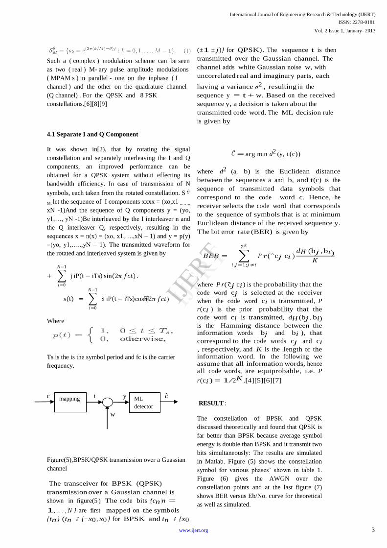
Figure(5),BPSK/QPSK transmission over a Guassian
channel
The transceiver for BPSK (QPSK)
transmission over a Gaussian channel is
shown in figure(5 ) The code bits {cn |n =
1, . . . , N } are first mapped on the symbols
{tn } (tn ∈ {−x0 , x0 } for BPSK and tn ∈ {x0
(±1 ± j)} for QPSK). The sequence t is then
transmitted over the Gaussian channel. The
channel adds white Gaussian noise w, with
uncorrelated real and imaginary parts, each
having a variance σ2 , resulting in the
sequence y = t + w. Based on the received
sequence y, a decision is taken about the
transmitted code word. The ML decision rule
is given by
𝐶 = arg min d2 (y, t(c))
where d2 (a, b) is the Euclidean distance
between the sequences a and b, and t(c) is the
sequence of transmitted data symbols that
correspond to the code word c. Hence, he
receiver selects the code word that corresponds
to the sequence of symbols that is at minimum
Euclidean distance of the received sequence y.
The bit error rate (BER) is given by
𝐵𝐸𝑅 = 𝑃 𝑟(ˆc𝑗 |c𝑖 )
2𝑘
𝑖 ,𝑗=1;𝑗≠𝑖
𝑑𝐻 (b𝑗 , b𝑖)𝐾
where P r( cj |ci ) is the probability that the
code word cj is selected at the receiver
when the code word ci is transmitted, P
r(ci ) is the prior probability that the
code word ci is transmitted, dH (bj , bi) is the Hamming distance between the information words bj and bi ), that
correspond to the code words cj and ci , respectively, and K is the length of the information word. In the following we assume that all information words, hence al l code words, are equiprobable, i.e. P
r(ci ) = 1/2K .[4][5][6][7]
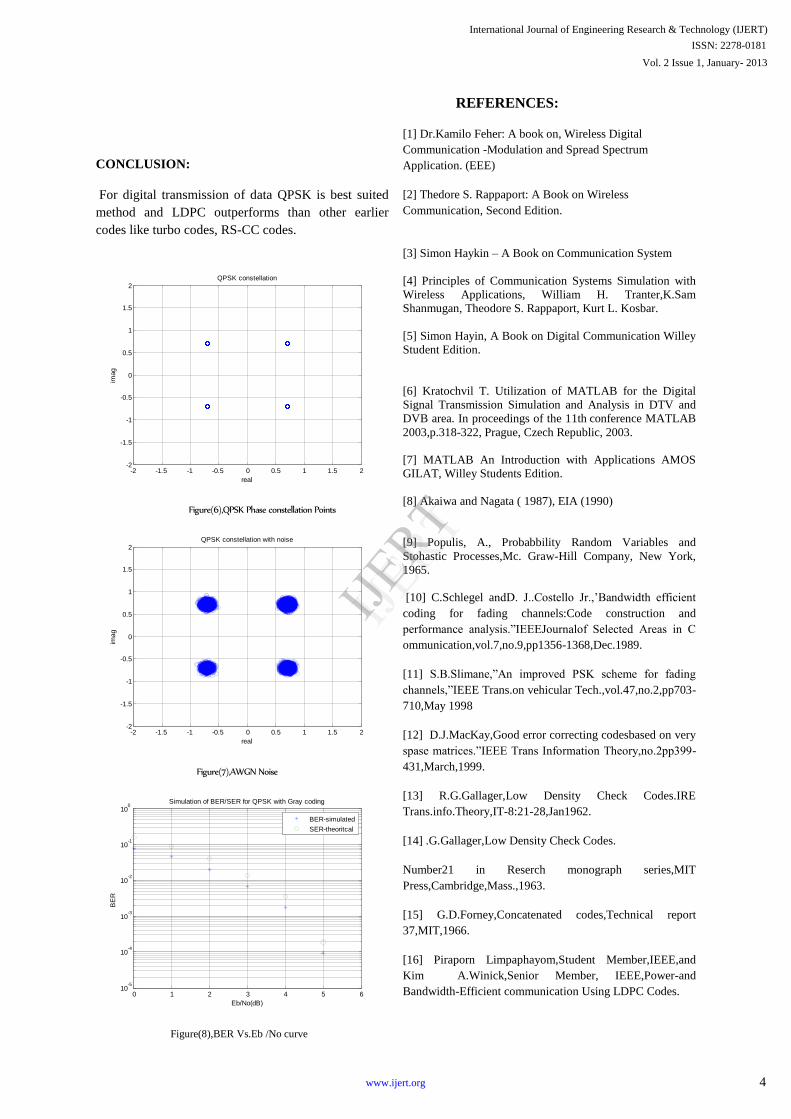
RESULT :
The constellation of BPSK and QPSK
discussed theoretically and found that QPSK is
far better than BPSK because average symbol
energy is double than BPSK and it transmit two
bits simultaneously: The results are simulated
in Matlab. Figure (5) shows the constellation
symbol for various phases’ shown in table 1.
Figure (6) gives the AWGN over the
constellation points and at the last figure (7)
shows BER versus Eb/No. curve for theoretical
as well as simulated.
ML
detector
mapping
International Journal of Engineering Research & Technology (IJERT)
Vol. 2 Issue 1, January- 2013
ISSN: 2278-0181
3www.ijert.org
IJERT
IJERT
CONCLUSION:
For digital transmission of data QPSK is best suited
method and LDPC outperforms than other earlier
codes like turbo codes, RS-CC codes.
Figure(6),QPSK Phase constellation Points
Figure(7),AWGN Noise
Figure(8),BER Vs.Eb /No curve
REFERENCES:
[1] Dr.Kamilo Feher: A book on, Wireless Digital
Communication -Modulation and Spread Spectrum
Application. (EEE)
[2] Thedore S. Rappaport: A Book on Wireless
Communication, Second Edition.
[3] Simon Haykin – A Book on Communication System
[4] Principles of Communication Systems Simulation with
Wireless Applications, William H. Tranter,K.Sam
Shanmugan, Theodore S. Rappaport, Kurt L. Kosbar.
[5] Simon Hayin, A Book on Digital Communication Willey
Student Edition.
[6] Kratochvil T. Utilization of MATLAB for the Digital
Signal Transmission Simulation and Analysis in DTV and
DVB area. In proceedings of the 11th
conference MATLAB
2003,p.318-322, Prague, Czech Republic, 2003.
[7] MATLAB An Introduction with Applications AMOS
GILAT, Willey Students Edition.
[8] Akaiwa and Nagata ( 1987), EIA (1990)
[9] Populis, A., Probabbility Random Variables and
Stohastic Processes,Mc. Graw-Hill Company, New York,
1965.
[10] C.Schlegel andD. J..Costello Jr.,’Bandwidth efficient
coding for fading channels:Code construction and
performance analysis.”IEEEJournalof Selected Areas in C
ommunication,vol.7,no.9,pp1356-1368,Dec.1989.
[11] S.B.Slimane,”An improved PSK scheme for fading
channels,”IEEE Trans.on vehicular Tech.,vol.47,no.2,pp703-
710,May 1998
[12] D.J.MacKay,Good error correcting codesbased on very
spase matrices.”IEEE Trans Information Theory,no.2pp399-
431,March,1999.
[13] R.G.Gallager,Low Density Check Codes.IRE
Trans.info.Theory,IT-8:21-28,Jan1962.
[14] .G.Gallager,Low Density Check Codes.
Number21 in Reserch monograph series,MIT
Press,Cambridge,Mass.,1963.
[15] G.D.Forney,Concatenated codes,Technical report
37,MIT,1966.
[16] Piraporn Limpaphayom,Student Member,IEEE,and
Kim A.Winick,Senior Member, IEEE,Power-and
Bandwidth-Efficient communication Using LDPC Codes.
-2 -1.5 -1 -0.5 0 0.5 1 1.5 2-2
-1.5
-1
-0.5
0
0.5
1
1.5
2
real
imag
QPSK constellation
-2 -1.5 -1 -0.5 0 0.5 1 1.5 2-2
-1.5
-1
-0.5
0
0.5
1
1.5
2
real
imag
QPSK constellation with noise
0 1 2 3 4 5 610
-5
10-4
10-3
10-2
10-1
100
Eb/No(dB)
BE
R
Simulation of BER/SER for QPSK with Gray coding
BER-simulated
SER-theoritcal
International Journal of Engineering Research & Technology (IJERT)
Vol. 2 Issue 1, January- 2013
ISSN: 2278-0181
4www.ijert.org
IJERT
IJERT