Performance Evaluation of a Solar Hybrid Air- Conditioner
27
Performance Evaluation of a Solar Hybrid Air- Conditioner Nnamdi Cyprian Nwasuka ( [email protected] ) Abia State University https://orcid.org/0000-0003-3451-9962 Nduka Nwankwojike Michael Okpara University of Agriculture Uchechukwu Nwaiwu Abia State University Original Article Keywords: Solar Hybrid Air-Conditioner, photovoltaic cells, COP, temperature Posted Date: May 18th, 2021 DOI: https://doi.org/10.21203/rs.3.rs-503697/v1 License: This work is licensed under a Creative Commons Attribution 4.0 International License. Read Full License Version of Record: A version of this preprint was published at Proceedings on Engineering Sciences on November 10th, 2021. See the published version at https://doi.org/10.24874/PES03.04.010.
Transcript of Performance Evaluation of a Solar Hybrid Air- Conditioner
Performance Evaluation of a Solar Hybrid Air-ConditionerNnamdi Cyprian Nwasuka ( [email protected] )
Abia State University https://orcid.org/0000-0003-3451-9962Nduka Nwankwojike
Michael Okpara University of AgricultureUchechukwu Nwaiwu
Abia State University
Original Article
Keywords: Solar Hybrid Air-Conditioner, photovoltaic cells, COP, temperature
Posted Date: May 18th, 2021
DOI: https://doi.org/10.21203/rs.3.rs-503697/v1
License: This work is licensed under a Creative Commons Attribution 4.0 International License. Read Full License
Version of Record: A version of this preprint was published at Proceedings on Engineering Sciences onNovember 10th, 2021. See the published version at https://doi.org/10.24874/PES03.04.010.

Performance Evaluation of a Solar Hybrid Air-Conditioner
Nwasuka Nnamdi Cyprian1,a*,Nwankwojike B. Nduka2,b,Nwaiwu Uchechukwu3,c
1,3Department of Mechanical Engineering, Abia State University, Uturu, Nigeria
2Department of Mechanical Engineering, Michael Okpara University of Agriculture,
Umudike, Nigeria.
a*[email protected], [email protected],
ABSTRACT
This research presents a solar hybrid air-conditioning system with R410a refrigerant. The
sole aim was to compare the performance of a solar hybrid air-conditioner with that of the
conventional split-unit air-conditioning systems in the market today. From the experiments
conducted, the room temperature of a solar hybrid air conditioner was found to be :27.2,
27.0, 27.0, 27.2, 27.2, 27.0, 28.0, and 29.5 while that of the conventional air conditioner
was found to be:69,66,64,66,73,69,66,62 indicating that solar hybrid system had lower
values in terms of room temperature than that of the split units air conditioner. Laboratory
results, field assessments, and simulations clearly established that hybrid air conditioners
can deliver substantial energy savings and demand reduction. Therefore, in the present
study, performance evaluation of the solar hybrid system with that of the split units is used
to develop approximate analytical solutions for heat transfer in boundary layer flow and
heat transfer.
KEYWORDS Solar Hybrid Air-Conditioner, photovoltaic cells, COP, temperature.
Nomenclature:
LP-Low Pressure
HP-High Pressure
T1-The compressor inlet temperature
T2-The compressor outlet temperature
T3-The condenser inlet air temperature
T4-The condenser outlet air temperature
T5-The evaporator outlet air temperature
T6-The evaporator inlet air temperature
T7-The evaporator 2 outlet air temperature
T8-The evaporator 2 inlet air temperature
S1-Room temperature setup
S2 –Room 2 temperature
D1-Room temperature difference
SP – setting low pressure
PD – low pressure difference
CM-Compressor
E1-Evaporator fan speed 1
OF-Out fan
L1-Thermal load
V5-Valve 5
V6-Valve 6
COP-Coefficient of performance
Q = Amount of heat in KJ
ṁ = Air mass flow rate in kg/s
Δh = (h1 − h2) Enthalpy change in KJ/Kg.
INTRODUCTION
The energy consumption for residential buildings constitutes one-third of the world’s primary energy demand, while many today would argue that the demand increases rapidly as a result
of the increase in population growth and the need to improve standards of living in the world.
(Olatomilowa et al.., 2015). Non-stop use of different source of non-renewable energy is as
a result of the hike in fuel price and production of large amount of harmful gas into the
atmosphere (Kumar et al.., 2016). Air conditioning (AC) controls the temperature, relative
humidity, movement and purity of the air for human comfort. (Bhatu et al.., 2019);( (Kumar
et al.., 2016).There is an increase in demand for the production of air conditioning. Nowadays
improving standards of ventilation, global environmental awareness and increasing concerns
about indoor air quality have tremendous impact on changing the design of air-conditioners.
Solar air conditioner is one which uses solar energy to produce cold or hot air and do not
pollute the environment (Saudagar et al.., 2013 and Dennis 1984). An addition of a thermal
heat exchanger to this type of system, as investigated by this work, has the potential to be an
effective way of maximizing the system’s solar energy generation potential in a cost-effective
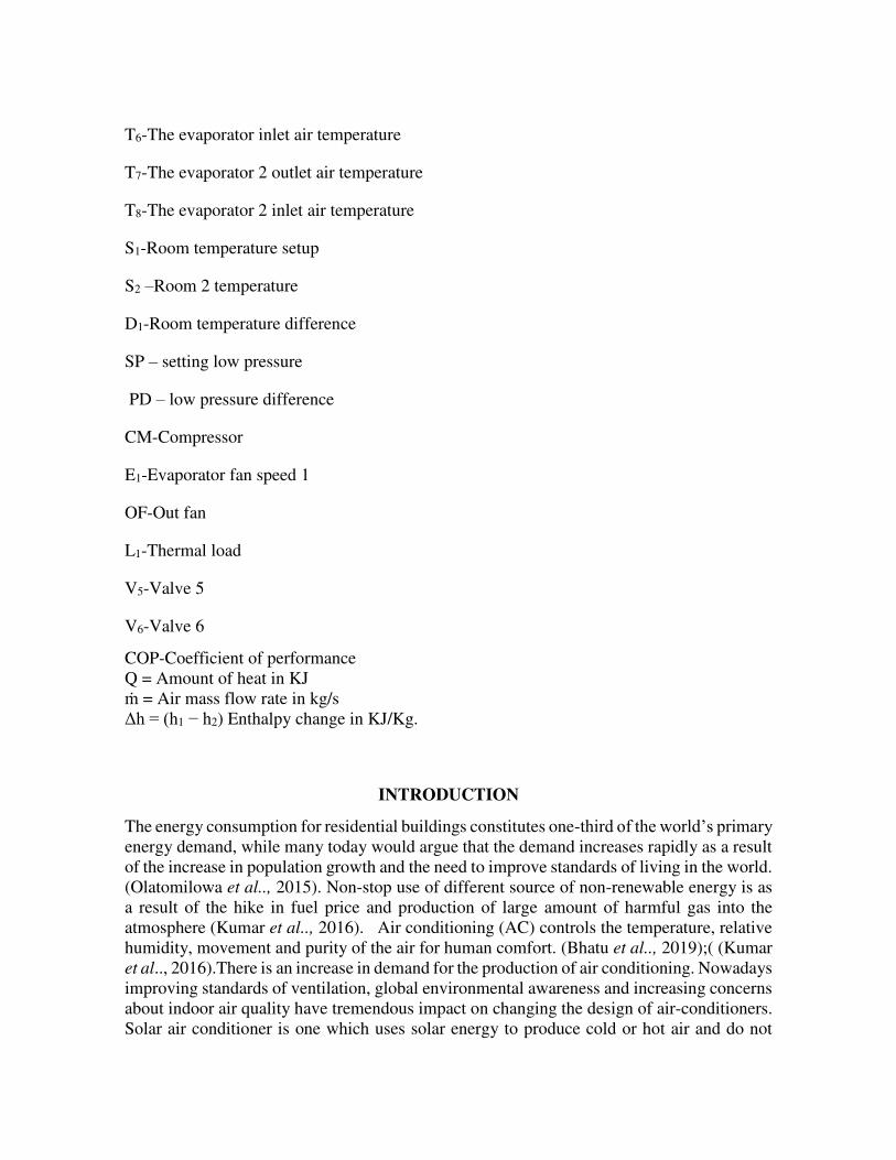
manner (Hassan et al 2018), (Ariff 2014). The pressure-volume and temperature-entropy
diagram for simple AC refrigeration cycle is shown in the figure below:
Fig. 1: PV and TS diagram of Conventional AC Refrigeration Cycle (Ariff 2014)
The PV and TS diagram of Conventional AC Refrigeration Cycle (Ariff 2014) shows that
Vapor compresses isentropically from point 1→ 2, and this increases the pressure from the evaporator to the condenser. At 2, phase change occurs as a result of constant heat rejection
as the vapor enters the condenser. At 3, latent heat is removed, then the liquid refrigerant
passes through the expansion valve in order to ensure that the enthalpy is constant and the
pressure is reduced. (Ariff 2014)
Fig. 2: PV and TS diagram of Designed Hybrid Solar AC Refrigeration Cycle (Ariff 2014)
Point 1 and 2 in the PV and TS diagram of designed hybrid solar AC Refrigeration Cycle
(Ariff 2014) are the respective design parameters for the electric compressor outlet and
solar compressor outlet. Point 2 is the solar compressor outlet, it is paramount to note that
these parameters varies as a result of the availability of sunlight. (Ariff 2014) Point 1, 3 and
4 are kept constant as the conventional system to achieve the same cooling capacity Hybrid
air conditioners are more efficient than conventional air conditioning technologies. Hybrids
has multiple subsystems that are selected for specific climates and applications. Ideally,

energy flow between subsystems is organized to gain more advantages, and operation of each
subsystem is coordinated so that a single machine operates in many discrete modes to provide
only the needed capacity with the least resource consumption. Researchers have proposed
and evaluated many unique hybrid system architectures. Laboratory studies, field
assessments, and simulations have clearly established that hybrid air conditioners can deliver
substantial energy savings and demand reduction. These studies have indicated annual energy
savings for cooling and ventilation between 30-90%, depending on climate, application, and
technology. However, it is difficult to make an informed assessment about which hybrid
systems are most appropriate for different buildings in different climates. Most researchers
have employed a mix of first-principle and empirical methods to model particular hybrid
systems by means of complex component by component models.
Given the complexity of this process, no researcher has conducted a thorough
parametric assessment of a wide variety of hybrid systems in different climates and
applications. Since every researcher employs different analytical methods and uses different
performance assessment metrics, literature review to compare the various hybrid systems
evaluated in separate studies only provides limited insight. Consequently, thorough
assessment of alternative hybrid strategies has heretofore been infeasible for engineers in
practice. In response to these challenges, through this project we developed a generalized
empirical method to model the performance of hybrid unitary air conditioners within building
energy simulations (Modera and Wooley 2017).
Ravi et al (2015) stated that water and energy were the basis necessity for humans in
other to live a normal life on earth. Solar energy technologies have proved to be useful for
the developing and under developed countries in order to sustain their energy needs. Solar
cooling is a good example of addressing climate changes. Long term data should be used to
prove the feasibilities of air conditioning systems. Saudagar et al (2013) reviewed new solar
based air conditioning techniques. These techniques used solar energy to produce cold or hot
air and do not pollute the environment. Saudagar et al (2013) and Naskar et al (2018) reported
the application of Air-Conditioner increases day to day as home appliances and in industry
from the last decade.
Fig.3.Predicted mean cell of a hybrid solar air- conditioner (Hassan et al 2018)

Today, the predicted mean cell of a hybrid solar air- conditioner consumption of electricity
decreased repeatedly and reduction of fossil fuel resources brought about a significant role
in the development of eco-friendly and energy efficient technologies. (Kumar et al.., 2016),
(Kaidir et al.., 2017) and (Borane et al.., 2019) reported the performance of the hybrid air-
conditioning system. For a chosen regeneration temperature, the hybrid system is
economically up to certain humidity level compared to split unit air condition alone (Yasser
et al.., 2016 and Avijit and Hasan 2018). Therefore, in the present study, performance
evaluation of the solar hybrid system with that of the split units is used to develop
approximate analytical solutions for heat transfer in boundary layer flow and heat transfer.
MATERIALS AND METHOD
The hybrid solar system comprises six main components: a compressor, air-cooled
condenser, an expansion device, an evaporator, conventional solar collector and a storage
tank of hot water. The schematics is shown in figure 4 below. The refrigerant contains a
mixture of liquid and vapor and they enter the evaporator (point-1). Evaporator coil absorbs
the heat from hot air the liquid becomes superheated at the evaporator outlet, and enters the
compressor (point 2), where increasing pressure causes increase in refrigerant temperature.
The vacuum solar panel heats up the water. Refrigerant from the compressor now passes
through the copper coil in heat exchange tank (point 3). Once the conditioned air temperature
reaches the required temperature, the compressor would automatically go off. However,
during the compression stage, the additional heat absorbed must be rejected in the condenser.
Further reduction will occur at point 4; thus, the sub-cooled liquid finds its way to the
expansion device at point 5.

Fig 4: Flow diagram of solar hybrid system (Kumar et al.., 2016).
The figure 4 above shows the flow diagram of solar hybrid system (Kumar et al.., 2016).It is
paramount to note the hybrid air conditioner runs on both electricity and solar energy. In this
era, hybrid solar air - conditioner used more because it is environmentally friendly and does
not produce any harmful gases. Hybrid solar system reduces power consumption than normal
air conditioner. This system uses solar energy as heat that is as additional heat sources to help
the more energy required operating the cooling process of the solar system typical air
conditioning to reduce consumption 'energy’. Now a days R-410a refrigerant is generally
used because it is eco-friendly (Kumar et al.., 2016).
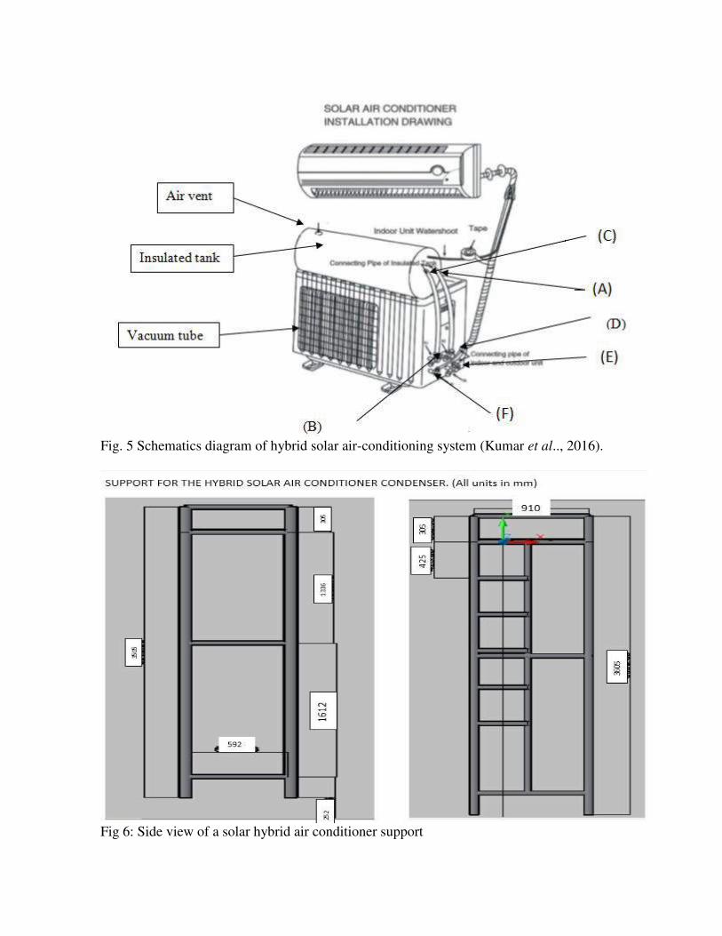
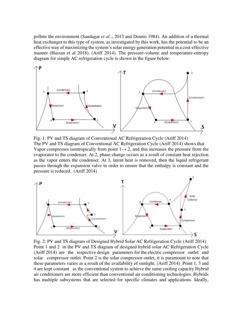
Fig. 5 Schematics diagram of hybrid solar air-conditioning system (Kumar et al.., 2016).
Fig 6: Side view of a solar hybrid air conditioner support

Fig. 7: Showing the structures used to mount the solar hybrid air conditioner
Experimental Set Up
In figure 8, the schematic of the measurement setup is shown. The green dots are the pressure
gauges (referred to as P), the red dots are the temperature sensors (referred to as T). Before
and after each component the temperature is measured to be able to calculate the energy
balances. Also for several points the pressure is measured. From the combined results of
pressure and temperature the enthalpy of the refrigerant can be calculated.
Fig. 8 schematic of measurement setup (Kumar et al..,2016)

Evaporator
Evaporator is in lower pressure side. The evaporator consists of coils of pipe wound round
that will permit the liquid-vapor refrigerant at low pressure and temperature to be evaporated
and changed into vapor refrigerant at low pressure and temperature.
Capillary tube
This is the best metering devices used today in refrigeration systems and air conditioning
industries. It consists of copper tube of minute internal diameter. It is of very great length
and is wound several turns to occupy less space.
Water storage tank.
The storage water in water tank is heated by the vacuum solar collector uses solar radiation.
For this research, a vacuum solar tube is a two- layered glass tube and vacuum is provided in
between them. Therefore, there is a required very good insulation barrier, preventing losses
of heat due to convection and conduction.
Compressor
The compressor absorbs the low pressure and temperature vapor refrigerant from evaporator
through the compressor inlet, and compress it to a high pressure and temperature. This high
pressure and temperature vapor refrigerant is discharged into the condenser through the
outlet.
Condenser
This system involves the transfer of heat. In doing so, latent heat is given off by the substance
and will be transferred to the condenser coolant.
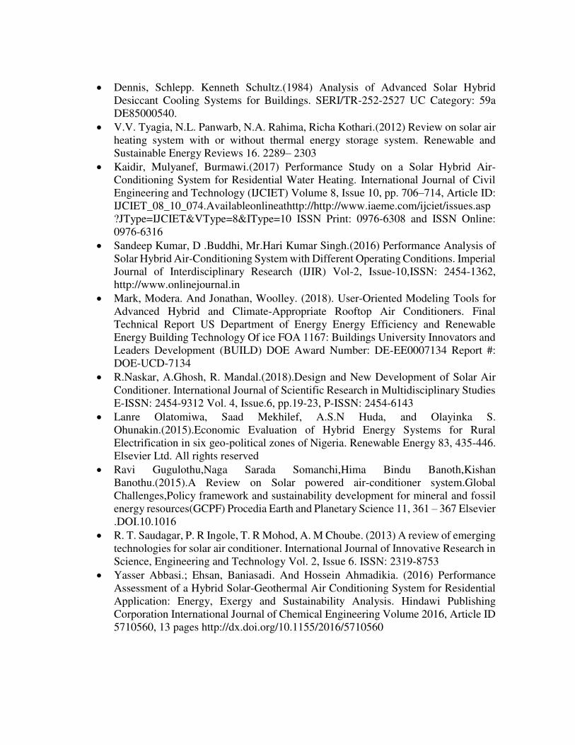
Evacuated tube Solar Collector
Solar powered system needs solar collector which working by absorbing radiation from the
sunlight and converting them into heat.
Fig. 9: Evacuated tube Solar Collector (Kumar et al..,2016)
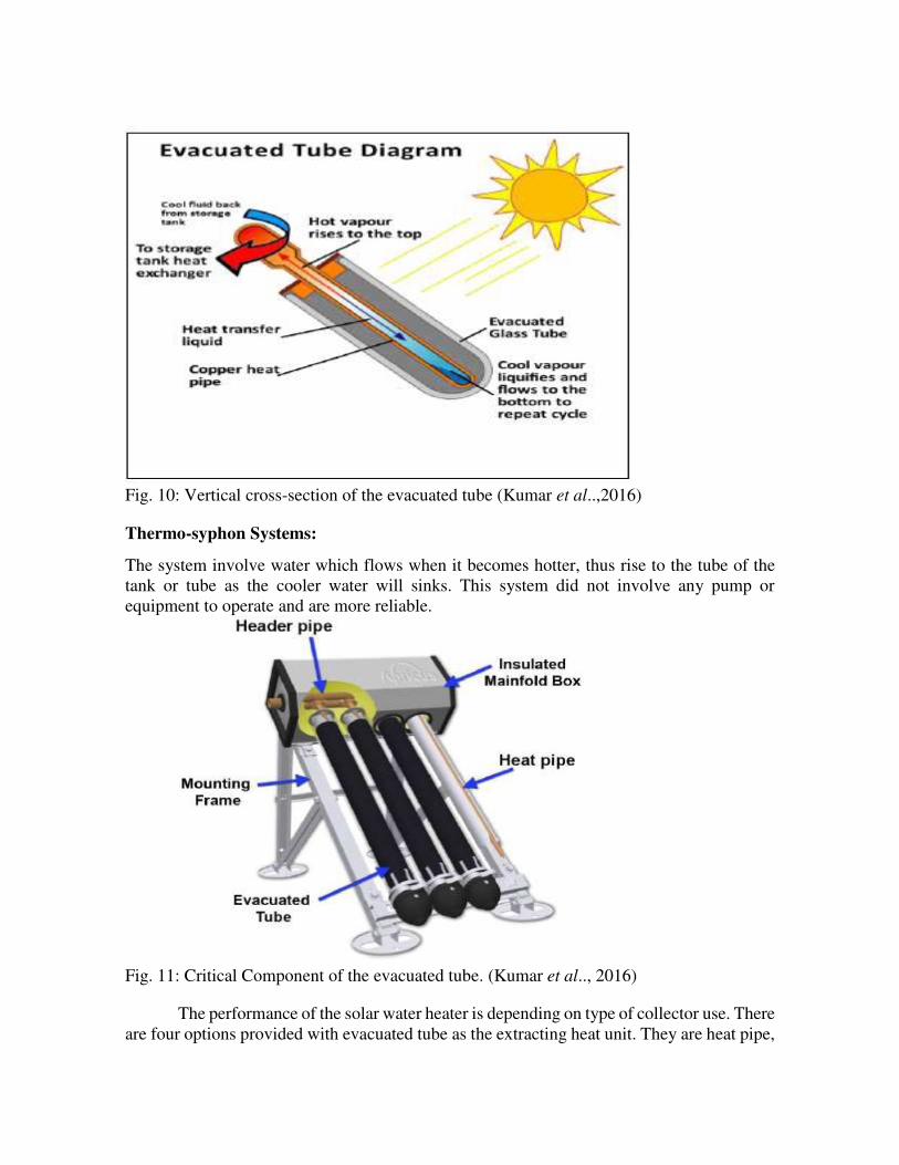
Fig. 10: Vertical cross-section of the evacuated tube (Kumar et al..,2016)
Thermo-syphon Systems:
The system involve water which flows when it becomes hotter, thus rise to the tube of the
tank or tube as the cooler water will sinks. This system did not involve any pump or
equipment to operate and are more reliable.
Fig. 11: Critical Component of the evacuated tube. (Kumar et al.., 2016)
The performance of the solar water heater is depending on type of collector use. There
are four options provided with evacuated tube as the extracting heat unit. They are heat pipe,
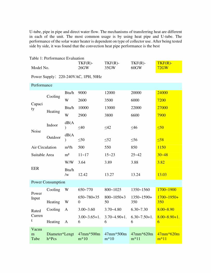
U-tube, pipe in pipe and direct water flow. The mechanisms of transferring heat are different
in each of the unit. The most common usage is by using heat pipe and U-tube. The
performance of the solar water heater is dependent on type of collector use. After being tested
side by side, it was found that the convection heat pipe performance is the best
Table 1: Performance Evaluation
Model No.
TKF(R)-
26GW
TKF(R)-
35GW
TKF(R)-
60GW
TKF(R)-
72GW
Power Supply:220-240VAC, 1PH, 50Hz
Performance
Capaci
ty
Cooling Btu/h 9000 12000 20000 24000
W 2600 3500 6000 7200
Heating Btu/h 10000 13000 22000 27000
W 2900 3800 6600 7900
Noise
Indoor dB(A
) ≤40 ≤42 ≤46 ≤50
Outdoor dB(A
) ≤50 ≤52 ≤56 ≤58
Air Circulation m³/h 500 550 850 1150
Suitable Area m² 11~17 15~23 25~42 30~48
EER
W/W 3.64 3.89 3.88 3.82
Btu/h
/w 12.42 13.27 13.24 13.03
Power Consumption
Power
Input
Cooling W 650~770 800~1025 1350~1560 1700~1900
Heating W
650~780+35
0
800~1050+3
50
1350~1590+
350
1700~1950+
350
Rated
Curren
t
Cooling A 3.00~3.60 3.70~4.80 6.30~7.30 8.00~8.90
Heating A
3.00~3.65+1.
6
3.70~4.90+1.
6
6.30~7.50+1.
6
8.00~8.90+1.
6
Vacuu
m
Tube
Diameter*Lengt
h*Pcs
47mm*500m
m*10
47mm*500m
m*10
47mm*620m
m*11
47mm*620m
m*11

Dimensions
Indoor
Unit
Net mm
802*265*19
0
880*286*20
3
940*300*22
0
1080*220*3
00
Shippin
g mm
860*325*25
5
935*350*27
0
1003*360*2
80
1136*285*3
60
Outdo
or Unit
Net mm
790*260*54
0
790*260*54
0
850*300*75
5
940*300*75
5
Shippin
g mm
910*370*61
0
910*370*61
0
950*410*76
0
990*400*77
0
Water
Tank
Shippin
g mm 910*400*33
0
910*400*33
0
980*400*37
0
980*400*37
0 Vacuu
m
Tube
Shippin
g mm
Weigh
t
Indoor
Unit
Net/Gro
ss kg 9/10.5 10/11.5 16/17.5 20/22
Outdo
or Unit
Net/Gro
ss kg 31/34 38/40 50/52 55/58
Solar
Collec
tor
Net/Gro
ss kg 13/15 13/15 16/17 16/17
Loadin
g Qty
in 20feet sets 66 66 49 46
40HQ sets 162 162 120 112
Quotation
Freon:R410
Coolin
g only
Ex-
work
price
USD 422.0
464.0 642.0 707.0
Coolin
g
&Heat
ing
Ex-
work
price
USD 435.0
476.0 655.0 727.0
Above, Red Numbers means that the electrical heater is on when tank water temp is
<65℃. Parameters in the form are measured in the rated working state: when cooling;
outdoor unit dry/wet-bulb temp 35/24℃, indoor unit dry/wet-bulb 27/19℃; when heating, outdoor unit dry/wet-bulb temp 7/6℃, indoor unit dry/wet-bulb 20/15℃, changes may appear according to real working state.
Comparative analysis between the solar hybrid air-conditioner and conventional
hybrid air conditioner was conducted on Feb-June 2016 at green house technology
department, Skill G Nigeria Limited, 4A Asa Street, Off Gana, Maitama Abuja in other to
ascertain the performance analysis of a solar hybrid air conditioning and conventional air-
conditioner, and to state if the performance was better than the normal system in the market
today.
The reading is taken using the following parameters:
1) Water tank temperature.
2) Energy Consumption.
3) Room temp.
4) Ambient temp.
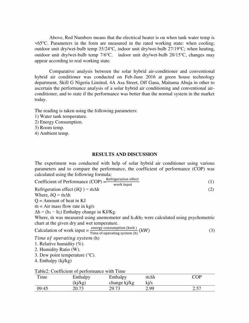
RESULTS AND DISCUSSION
The experiment was conducted with help of solar hybrid air conditioner using various
parameters and to compare the performance, the coefficient of performance (COP) was
calculated using the following formula:
Coefficient of Performance (COP) =Refrigeration effect work input (1)
Refrigeration effect (δQ ) = ṁΔh (2)
Where, δQ = ṁΔh
Q = Amount of heat in KJ
ṁ = Air mass flow rate in kg/s
Δh = (h1 − h2) Enthalpy change in KJ/Kg.
Where, ṁ was measured using anemometer and h1&h2 were calculated using psychometric
chart at the given dry and wet temperature.
Calculation of work input = energy consumption (kwh )Time of operating system (h) (kW) (3) 𝑇𝑖𝑚𝑒 𝑜𝑓 𝑜𝑝𝑒𝑟𝑎𝑡𝑖𝑛𝑔 𝑠𝑦𝑠𝑡𝑒𝑚 (h)
1. Relative humidity (%).
2. Humidity Ratio (W).
3. Dew point temperature (°C).
4. Enthalpy (kj/kg)
Table2: Coefficient of performance with Time
Time Enthalpy
(kj/kg)
Enthalpy
change kj/kg
ṁΔh
kj/s
COP
09:45 20.73 29.73 2.99 2.57

10:15 25.65 30.53 3.08 2.65
10:45 27.13 26.61 2.69 2.31
11:15 24.07 32.03 3.23 2.78
11:45 23.64 30.11 3.04 2.62
12:15 23.64 30.24 3.05 2.63
12:45 25.3 28.86 2.91 2.51
01:15 28.2 37.58 3.79 3.27
01:45 28.13 32.66 3.29 2.84
02:15 27.07 31.7 3.2 2.76
02:45 28.32 33.51 3.38 2.91
03:15 30.26 30.53 3.08 2.65
Fig. 12: Coefficient of performance with Time
Table 3: Analysis of solar hybrid air conditioner temperature measurement
Time Suctio
n Inlet
Dry
Bulb
Temp.
(°C)
Suctio
n Inlet
Wet
Bulb
Temp.
(°C)
Discharg
e Outlet
Dry
Bulb
Temp.
(°C)
Discharg
e Outlet
Wet
Bulb
Temp.
(°C)
Water
Temp.
(°C)
Roo
m
Temp
. (°C)
Ambien
t
Temp.
(°C)
Energy
Electrical
consumptio
n
difference
(kwh
09:1
5
26.97 26.97 26.97 26.97 49.75 27.2 28
09:4
5
26.30 17.91 6.00 63.00 63.71 27.0 28 0.5
10:1
5
27.66 19.72 8.39 8.63 74.87 27.0 29 0.6
10:4
5
28.98 19.00 8.39 8.63 83.94 27.2 29 0.6
11:1
5
27.87 19.70 9.06 9.52 83.01 27.2 33 0.6
11:4
5
28.77 19.00 7.66 7.89 84.44 27.0 34 0.6
12:1
5
28.50 19.04 7.46 7.69 87.69 27.0 35 0.6
12:4
5
29.11 19.13 8.23 7.69 89.39 28.0 36 0.6
0.00
1.00
2.00
3.00
4.00
09:45 10:15 10:45 11:15 11:45 12:15 12:45 01:15 01:45 02:15 02:45 03:15
CO
P
Time (Min.)

01:1
5
31.72 22.40 9.73 8.46 92.29 29.5 36 0.6
01:4
5
31.72 21.09 9.50 9.73 92.05 29.5 37 0.6
02:1
5
29.77 20.50 9.03 9.50 91.72 28.0 37 0.6
02:4
5
29.72 21.36 9.59 10.75 94.24 27.5 34 0.6
03:1
5
31.50 21.09 10.43 12.52 103.8
5
29.5 33 0.6
Fig. 13: Room temperature varies with increase in time for solar hybrid air-conditioner
The hybrid systems tend to cool the temperature of the room for a very long time, before the
room heats up again. As the hybrid solar air-conditioner parameters increases, the rate of heat
transferred through the solar tubes increases while the temperatures in the room drops. Also
the results also shows that the ratio of the convective heat transferred to the conductive heat
transferred has much effect on the temperature distribution along the hybrid solar system, the
rate of heat transferred at the base of the solar hybrid tubes and the coefficient of performance
of the system. As the coefficient of heat transferred h increases, the ratio of the coefficient of
heat transferred and the thermal conductivity of the solar tubes material increases at the base
of the system and eventually, the temperature distribution along the solar tubes, especially at
the tip of the tubes increases. This shows that coefficient of performance of the solar air
conditioning is achieved at high values of the geothermal region.
Table 4: Cooling system of a conventional air conditioning system.
S/N S10F D1
0F T50F T6
0F V5 S20F D2
0F T70F T8
0F V60F LP(psi) HP(psi) CM OF t(mins)
1 64 9 66 69 ON 68 9 69 75 ON 42 135 ON ON 2:30
2 64 9 60 66 ON 68 9 64 71 ON 37 131 ON ON 5:00
3 64 9 59 64 OFF 68 9 62 69 ON 37 131 ON ON 7:50
4 64 9 66 66 OFF 68 9 60 66 OFF 35 115 OF OF 10:00
5 64 9 73 73 ON 68 9 71 71 OFF 52 109 On On 12:30
6 64 9 66 69 ON 68 9 75 75 ON 47 133 ON ON 15:00
7 64 9 62 66 ON 68 9 71 71 ON 42 133 ON ON 17:30
8 64 9 59 62 OFF 68 9 68 68 ON 35 131 ON ON 20:00
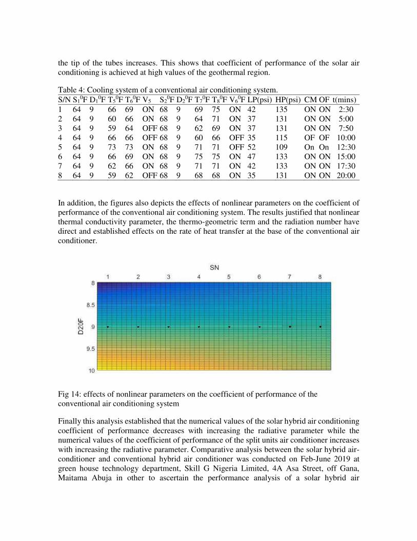
In addition, the figures also depicts the effects of nonlinear parameters on the coefficient of
performance of the conventional air conditioning system. The results justified that nonlinear
thermal conductivity parameter, the thermo-geometric term and the radiation number have
direct and established effects on the rate of heat transfer at the base of the conventional air
conditioner.
Fig 14: effects of nonlinear parameters on the coefficient of performance of the
conventional air conditioning system
Finally this analysis established that the numerical values of the solar hybrid air conditioning
coefficient of performance decreases with increasing the radiative parameter while the
numerical values of the coefficient of performance of the split units air conditioner increases
with increasing the radiative parameter. Comparative analysis between the solar hybrid air-
conditioner and conventional hybrid air conditioner was conducted on Feb-June 2019 at
green house technology department, Skill G Nigeria Limited, 4A Asa Street, off Gana,
Maitama Abuja in other to ascertain the performance analysis of a solar hybrid air

conditioning and conventional air-conditioner, and to state if the performance was better than
the normal system in the market today
CONCLUSION
The hybrid solar air-conditioning is a new innovation that is rocking the world today. Its sole
aim was to provide better comfort, efficiency and it has less effect on the ecosystem. From
the experiments conducted, the room temperature of a solar hybrid air conditioner was found
to be :27.2, 27.0, 27.0, 27.2, 27.2, 27.0, 28.0, and 29.5 while that of the conventional air
conditioner was found to be:69,66,64,66,73,69,66,62 indicating that solar hybrid system had
lower values in terms of room temperature than that of the split units air conditioner. When
compared with the conventional systems today, the solar hybrid air-conditioner performed
better, the conventional system has a higher room temperature thereby making the
compressor to perform more work in order to achieve better cooling while the solar hybrid
air conditioner requires lesser work to achieve its cooling.
AVAILABILITY OF DATA AND MATERIALS
Not applicable
COMPETING INTEREST
The authors declare that they do not have any competing interest.
FUNDING
No funding
AUTHORS CONTRIBUTION
NNC, made a substantial contribution to conception and design of the manuscript, NBN
supervised the work and made excellent contributions towards the analysis and compilation
of the work.NU carried out performance analysis of the work.
ACKNOWLEDGEMENTS
This research would not have been possible without the excellent contributions of my
supervisor, Prof Nwankwojike B. Nduka. His enthusiasm, knowledge and technical know-
how, helped ensured that my work was kept on track.
REFERENCES
Ariff Rahman Bin Ishak.( 2014). Study of Hybrid Solar Air Conditioning. Universiti
Teknologi Petronas Bandar Seri Iskandar 31750 Tronoh Perak Darl Ridzuan.
Avijit Mallik, Md. Zahid Hasan.(2018). PV/T Systems for Renewable Energy
Storage: A Review. World Scientific News 96. 83-95.EISSN 2392-2192
Bhatu R. Borane, Dr. Vijay H. Patil, Prof T.A Koli. (2019) A Review Paper on
Performance Evaluation of Desiccant Wheel with Comparative Study of
Dehumidification using Various Desiccant Material used in Hybrid Air Conditioning.
International Journal of Innovations in Engineering and Science, Vol 4, No.10. E-
ISSN: 2456-3463 www.ijies.net. Impact Factor Value 6.046
Dennis, Schlepp. Kenneth Schultz.(1984) Analysis of Advanced Solar Hybrid
Desiccant Cooling Systems for Buildings. SERI/TR-252-2527 UC Category: 59a
DE85000540.
V.V. Tyagia, N.L. Panwarb, N.A. Rahima, Richa Kothari.(2012) Review on solar air
heating system with or without thermal energy storage system. Renewable and
Sustainable Energy Reviews 16. 2289– 2303
Kaidir, Mulyanef, Burmawi.(2017) Performance Study on a Solar Hybrid Air-
Conditioning System for Residential Water Heating. International Journal of Civil
Engineering and Technology (IJCIET) Volume 8, Issue 10, pp. 706–714, Article ID:
IJCIET_08_10_074.Availableonlineathttp://http://www.iaeme.com/ijciet/issues.asp
?JType=IJCIET&VType=8&IType=10 ISSN Print: 0976-6308 and ISSN Online:
0976-6316
Sandeep Kumar, D .Buddhi, Mr.Hari Kumar Singh.(2016) Performance Analysis of
Solar Hybrid Air-Conditioning System with Different Operating Conditions. Imperial
Journal of Interdisciplinary Research (IJIR) Vol-2, Issue-10,ISSN: 2454-1362,
http://www.onlinejournal.in
Mark, Modera. And Jonathan, Woolley. (2018). User-Oriented Modeling Tools for
Advanced Hybrid and Climate-Appropriate Rooftop Air Conditioners. Final
Technical Report US Department of Energy Energy Efficiency and Renewable
Energy Building Technology Of ice FOA 1167: Buildings University Innovators and
Leaders Development (BUILD) DOE Award Number: DE-EE0007134 Report #:
DOE-UCD-7134
R.Naskar, A.Ghosh, R. Mandal.(2018).Design and New Development of Solar Air
Conditioner. International Journal of Scientific Research in Multidisciplinary Studies
E-ISSN: 2454-9312 Vol. 4, Issue.6, pp.19-23, P-ISSN: 2454-6143
Lanre Olatomiwa, Saad Mekhilef, A.S.N Huda, and Olayinka S.
Ohunakin.(2015).Economic Evaluation of Hybrid Energy Systems for Rural
Electrification in six geo-political zones of Nigeria. Renewable Energy 83, 435-446.
Elsevier Ltd. All rights reserved
Ravi Gugulothu,Naga Sarada Somanchi,Hima Bindu Banoth,Kishan
Banothu.(2015).A Review on Solar powered air-conditioner system.Global
Challenges,Policy framework and sustainability development for mineral and fossil
energy resources(GCPF) Procedia Earth and Planetary Science 11, 361 – 367 Elsevier
.DOI.10.1016
R. T. Saudagar, P. R Ingole, T. R Mohod, A. M Choube. (2013) A review of emerging
technologies for solar air conditioner. International Journal of Innovative Research in
Science, Engineering and Technology Vol. 2, Issue 6. ISSN: 2319-8753
Yasser Abbasi.; Ehsan, Baniasadi. And Hossein Ahmadikia. (2016) Performance
Assessment of a Hybrid Solar-Geothermal Air Conditioning System for Residential
Application: Energy, Exergy and Sustainability Analysis. Hindawi Publishing
Corporation International Journal of Chemical Engineering Volume 2016, Article ID
5710560, 13 pages http://dx.doi.org/10.1155/2016/5710560

Figures
Figure 1
PV and TS diagram of Conventional AC Refrigeration Cycle (Ariff 2014)
Figure 2
PV and TS diagram of Designed Hybrid Solar AC Refrigeration Cycle (Ariff 2014)

Figure 3
Predicted mean cell of a hybrid solar air- conditioner (Hassan et al 2018)
Figure 4
Flow diagram of solar hybrid system (Kumar et al.., 2016).

Figure 5
Schematics diagram of hybrid solar air-conditioning system (Kumar et al.., 2016).

Figure 6
Side view of a solar hybrid air conditioner support

Figure 7
Showing the structures used to mount the solar hybrid air conditioner
Figure 8
Schematic of measurement setup (Kumar et al..,2016)
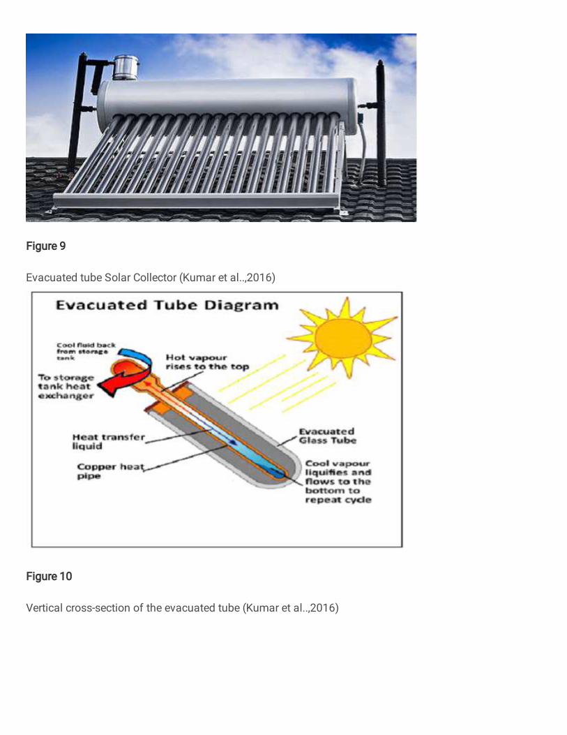
Figure 9
Evacuated tube Solar Collector (Kumar et al..,2016)
Figure 10
Vertical cross-section of the evacuated tube (Kumar et al..,2016)

Figure 11
Critical Component of the evacuated tube. (Kumar et al.., 2016)
Figure 12
Coe�cient of performance with Time

Figure 13
Room temperature varies with increase in time for solar hybrid air-conditioner
Figure 14
Effects of nonlinear parameters on the coe�cient of performance of the conventional air conditioningsystem