
Performance Evaluation of a Resonant-integrated Pumping System
4
Performance Evaluation of a Resonant-integrated Pumping System Lee Vincent Chieng-Chen Faculty of Engineering and Science, Curtin University Malaysia, Sarawak Abstract. Impedance pump is a simple valve-less pumping mechanism; it offers a low energy, low noise alternative at both macro- and micro-scale devices. It is also demonstrated to be a promising new technique for producing and amplifying net flow. There have been research studying the effects of series-connected impedance pump, where an increase in net flow is exhibited. In this study, an integrated system of conventional pump and impedance pump is introduced. This paper describes the performance evaluation of this integrated pumping system, with emphasis on the amount of amplification induced as a function of Womersley number (normalized excitation frequency) and normalized pressure head. Due to the nature of the resonant valve-less impedance pump, the integrated pumping system exhibits similar behaviour and characteristics as an impedance pump, such as the pulsatile nature of net flow. Results show positive outcomes where maximum amplification of 91.7% is demonstrated at resonance. 1 Introduction Impedance pump is a very simple design that offers a promising new technique for producing and amplifying a net flow for both macro- and micro-scale devices [1, 2]. The impedance pump is a valve-less pump, which does not require impellers to operate. It is formed by joining a flexible tube to rigid sections. Asymmetrical excitation at a single location of the fluid-filled elastic tube will result in unidirectional flow due to the mismatch in impedance. Such pumping mechanism has shown to be highly sensitive towards the impedance in the tube, the location, and excitation frequency [1, 3-6]. The first demonstration of valve-less pumping through an impedance pump, was demonstrated by Gerhart Liebau in 1954, using an elastic tube connected to reservoirs at different heights [7, 8]. Following Liebau’s work in 1954, there have been several research studying the underlying physics of the system, be it numerical or experimental. It was then, that the pump showed possibility in flow amplification. In recent years, study on sequential excitations on a single elastic tube shows promising results where increase in net flow is evident [9]. Other work on flow amplification includes design which incorporates multi-stage impedance pumping system [10] with flow enhancement of 69%. Numerical study on flow amplification, integrating a steady and oscillating flow is also presented, where an estimated amplification of 120% is demonstrated [11]. The results are, however, not validated with any experimental data. With reference to that study, it shows that amplification of flow rate is indeed achievable with the aid of impedance pump. This study aims to prove this concept experimentally. The focus of this study is the amount of amplification induced, demonstrated as a function of Womersley number (normalized excitation frequency) and normalized pressure head during activation of the impedance pump. 2 Experimental methods and materials The integrated pumping system utilises a modified version of the conventional impedance pump setup in Ref [10] with flow discharge at variable pressure heads. Figure 1 shows the schematic diagram of a modified two- stage open-loop impedance pump with flow discharge of variable pressure heads. Water inlet is connected in line as the silicone rubber tube to the source reservoir (reservoir on the left) as illustrated in the figure, from a water pump model DB-330A with power rating of 330 Watts with flow rate of 6 L/min. The water pump will transport the water from its source into the reservoir. Multiple flow discharges of variable pressure heads are configured on the deliverable reservoir (reservoir on the right) as illustrated, where the flow rates are measured. The pressure heads are configured at height difference of 0 to 60 mm (pressure head difference of 0 to 735 Pa) with 20 mm interval above the initial water level of 250 mm. These data will serve as the benchmarking data for the integrated pumping system. The elastic silicone rubber tube will then be excited simultaneously while water pump is transporting the water through the discharge. Flow rates, with additional effect from the excitations, are measured and analysed against the benchmarking data for comparison. The analysis of the flow dynamics will be in its non-dimensional form. Detailed analysis method are available in Ref [12]. © The Authors, published by EDP Sciences. This is an open access article distributed under the terms of the Creative Commons Attribution License 4.0 (http://creativecommons.org/licenses/by/4.0/). MATEC Web of Conferences 202, 02009 (2018) https://doi.org/10.1051/matecconf/201820202009 AAME 2018
Transcript of Performance Evaluation of a Resonant-integrated Pumping System

Performance Evaluation of a Resonant-integrated Pumping System
Lee Vincent Chieng-Chen
Faculty of Engineering and Science, Curtin University Malaysia, Sarawak
Abstract. Impedance pump is a simple valve-less pumping mechanism; it offers a low energy, low noise alternative
at both macro- and micro-scale devices. It is also demonstrated to be a promising new technique for producing and
amplifying net flow. There have been research studying the effects of series-connected impedance pump, where an
increase in net flow is exhibited. In this study, an integrated system of conventional pump and impedance pump is
introduced. This paper describes the performance evaluation of this integrated pumping system, with emphasis on the
amount of amplification induced as a function of Womersley number (normalized excitation frequency) and
normalized pressure head. Due to the nature of the resonant valve-less impedance pump, the integrated pumping
system exhibits similar behaviour and characteristics as an impedance pump, such as the pulsatile nature of net flow.
Results show positive outcomes where maximum amplification of 91.7% is demonstrated at resonance.
1 Introduction
Impedance pump is a very simple design that offers a
promising new technique for producing and amplifying a
net flow for both macro- and micro-scale devices [1, 2].
The impedance pump is a valve-less pump, which does
not require impellers to operate. It is formed by joining a flexible tube to rigid sections. Asymmetrical excitation
at a single location of the fluid-filled elastic tube will
result in unidirectional flow due to the mismatch in
impedance. Such pumping mechanism has shown to be
highly sensitive towards the impedance in the tube, the
location, and excitation frequency [1, 3-6].
The first demonstration of valve-less pumping
through an impedance pump, was demonstrated by
Gerhart Liebau in 1954, using an elastic tube connected
to reservoirs at different heights [7, 8]. Following
Liebau’s work in 1954, there have been several research studying the underlying physics of the system, be it
numerical or experimental. It was then, that the pump
showed possibility in flow amplification. In recent years,
study on sequential excitations on a single elastic tube
shows promising results where increase in net flow is
evident [9]. Other work on flow amplification includes
design which incorporates multi-stage impedance
pumping system [10] with flow enhancement of 69%.
Numerical study on flow amplification, integrating a
steady and oscillating flow is also presented, where an
estimated amplification of 120% is demonstrated [11].
The results are, however, not validated with any experimental data. With reference to that study, it shows
that amplification of flow rate is indeed achievable with
the aid of impedance pump. This study aims to prove this
concept experimentally. The focus of this study is the
amount of amplification induced, demonstrated as a
function of Womersley number (normalized excitation
frequency) and normalized pressure head during
activation of the impedance pump.
2 Experimental methods and materials
The integrated pumping system utilises a modified
version of the conventional impedance pump setup in Ref
[10] with flow discharge at variable pressure heads.
Figure 1 shows the schematic diagram of a modified two-
stage open-loop impedance pump with flow discharge of
variable pressure heads. Water inlet is connected in line
as the silicone rubber tube to the source reservoir
(reservoir on the left) as illustrated in the figure, from a
water pump model DB-330A with power rating of 330
Watts with flow rate of 6 L/min. The water pump will transport the water from its source into the reservoir.
Multiple flow discharges of variable pressure heads are
configured on the deliverable reservoir (reservoir on the
right) as illustrated, where the flow rates are measured.
The pressure heads are configured at height difference of
0 to 60 mm (pressure head difference of 0 to 735 Pa) with
20 mm interval above the initial water level of 250 mm.
These data will serve as the benchmarking data for the
integrated pumping system. The elastic silicone rubber
tube will then be excited simultaneously while water
pump is transporting the water through the discharge.
Flow rates, with additional effect from the excitations, are measured and analysed against the benchmarking data for
comparison. The analysis of the flow dynamics will be in
its non-dimensional form. Detailed analysis method are
available in Ref [12].
© The Authors, published by EDP Sciences. This is an open access article distributed under the terms of the Creative Commons Attribution License 4.0
(http://creativecommons.org/licenses/by/4.0/).
MATEC Web of Conferences 202, 02009 (2018) https://doi.org/10.1051/matecconf/201820202009AAME 2018
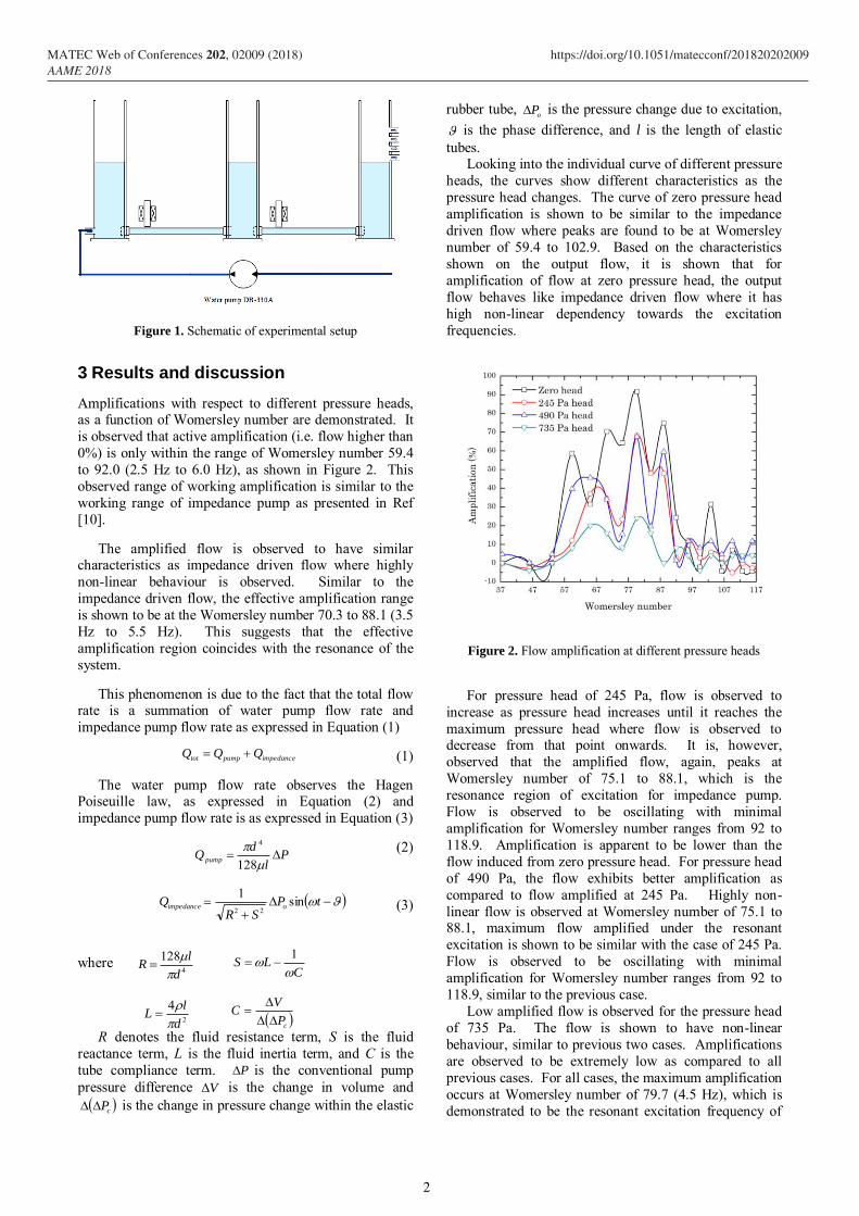
Figure 1. Schematic of experimental setup
3 Results and discussion
Amplifications with respect to different pressure heads, as a function of Womersley number are demonstrated. It
is observed that active amplification (i.e. flow higher than
0%) is only within the range of Womersley number 59.4
to 92.0 (2.5 Hz to 6.0 Hz), as shown in Figure 2. This
observed range of working amplification is similar to the
working range of impedance pump as presented in Ref
[10].
The amplified flow is observed to have similar characteristics as impedance driven flow where highly
non-linear behaviour is observed. Similar to the
impedance driven flow, the effective amplification range
is shown to be at the Womersley number 70.3 to 88.1 (3.5
Hz to 5.5 Hz). This suggests that the effective
amplification region coincides with the resonance of the
system.
This phenomenon is due to the fact that the total flow rate is a summation of water pump flow rate and
impedance pump flow rate as expressed in Equation (1)
(1)
The water pump flow rate observes the Hagen Poiseuille law, as expressed in Equation (2) and
impedance pump flow rate is as expressed in Equation (3)
(2)
(3)
where
R denotes the fluid resistance term, S is the fluid
reactance term, L is the fluid inertia term, and C is the
tube compliance term. P is the conventional pump
pressure difference V is the change in volume and
cP is the change in pressure change within the elastic
rubber tube, oP is the pressure change due to excitation,
is the phase difference, and l is the length of elastic
tubes. Looking into the individual curve of different pressure
heads, the curves show different characteristics as the
pressure head changes. The curve of zero pressure head
amplification is shown to be similar to the impedance
driven flow where peaks are found to be at Womersley
number of 59.4 to 102.9. Based on the characteristics
shown on the output flow, it is shown that for
amplification of flow at zero pressure head, the output
flow behaves like impedance driven flow where it has
high non-linear dependency towards the excitation
frequencies.
Figure 2. Flow amplification at different pressure heads
For pressure head of 245 Pa, flow is observed to
increase as pressure head increases until it reaches the
maximum pressure head where flow is observed to decrease from that point onwards. It is, however,
observed that the amplified flow, again, peaks at
Womersley number of 75.1 to 88.1, which is the
resonance region of excitation for impedance pump.
Flow is observed to be oscillating with minimal
amplification for Womersley number ranges from 92 to
118.9. Amplification is apparent to be lower than the
flow induced from zero pressure head. For pressure head
of 490 Pa, the flow exhibits better amplification as
compared to flow amplified at 245 Pa. Highly non-
linear flow is observed at Womersley number of 75.1 to 88.1, maximum flow amplified under the resonant
excitation is shown to be similar with the case of 245 Pa.
Flow is observed to be oscillating with minimal
amplification for Womersley number ranges from 92 to
118.9, similar to the previous case.
Low amplified flow is observed for the pressure head
of 735 Pa. The flow is shown to have non-linear
behaviour, similar to previous two cases. Amplifications
are observed to be extremely low as compared to all
previous cases. For all cases, the maximum amplification
occurs at Womersley number of 79.7 (4.5 Hz), which is
demonstrated to be the resonant excitation frequency of
impedancepumptot QQQ
Pl
dQ pump
128
4
tPSR
Q oimpedance sin1
22
4
128
d
lR
CLS
1
2
4
d
lL
cP
VC
2
MATEC Web of Conferences 202, 02009 (2018) https://doi.org/10.1051/matecconf/201820202009AAME 2018

the impedance pump. It is also suggested that the
excitation region of Womersley number ≤79.7 is the
amplification region; and that excitation region > 79.7 is
the suppression region for the system. Hence, a much
lower amplification is observed.
With reference to results presented in Figure 2, it is
shown that the excitation region of interest is within the
Womersley number 75.1, 79.7 and 84. A more in-depth
analysis of amplification and pressure head is made on
these three points of interest.
Figure 3(a) shows the normalized flow comparison
between a normal flow and the amplified flow at Womersley number of 75.1. As shown in the figure, the
trend for both curves is observed to be similar. The
normalized pressure head characterises the pressure head
in the reservoir, and it shows that as the pressure head
increases, the flow reduces in an oscillatory manner. The
flow is observed to reduce from zero pressure head till
0.1, then slight rise at 0.2 and decrease again at 0.3.
Ideally, flow rates of a conventional pump show a linear
decrease in magnitude against the pressure head. A
sinusoidal behaviour is observed, due to the elastic nature
of the tubes, that exhibits a moving boundary as opposed
to a rigid tube with fixed boundary. Therefore, it is showed that even with a steady flow from a pump passing
through an elastic tube, sinusoidal flow behaviour can be
expected. The amplified flow is observed to behave the
same way. Margin between the normal and amplified
flow is observed to narrow down as the pressure head
increases, indicating that the amplification effect reduces
as the pressure head increases. Reduction in the
amplification effect is seemed to be in a rather linear
manner.
Figure 3(b) shows the comparison between the
amplified and normal flow at Womersley number of 79.7. Amplification is found to be highest at this Womersley
number, where an amplification of 91.7% is
demonstrated. Based on the two curves, the margin of
amplification is observed to be quite parallel from zero
pressure head till normalized pressure head of 0.2. For
normalized pressure head of 0.2, the increment gradient
of amplified flow is shown to be higher than the normal
flow, suggesting a profound amplification effect at that
pressure head. For pressure head of 0.3 however, the
amplification effect is shown to decrease drastically.
The comparison of amplified and normal flow at
Womersley number of 84.0 is shown in Figure 3(c). Amplification effect is observed to be lower than 79.7.
The amplification curve is observed to decrease gradually
along the normalized pressure head from zero to 0.3;
whereas for the normal flow, the trend is observed to
reduce from zero pressure head till 0.1, followed by a
hike in 0.2 and a drop again at 0.3. The amplification
effect is however different from the previous two cases
where the margin is shown to be quite parallel from zero
pressure head to 0.1. From pressure head of 0.1 to 0.2
however, a drastic narrow margin is shown due to the
hike in normal flow but for continual decrement for the amplified flow. From 0.2 to 0.3, the margin is shown to
be parallel once again.
Figure 3. Flow amplification at Womersley number (a) 75.1 (b)
79.1, and (c) 84.0
In comparison to Ref [11] which reported an
amplification of approximate 120% at resonance, current experimental study shows that flow amplification through
integration of impedance pump is indeed possible.
Maximum flow amplification is demonstrated at 91.7% at
resonance. This shows that the amplification of flow is
3
MATEC Web of Conferences 202, 02009 (2018) https://doi.org/10.1051/matecconf/201820202009AAME 2018

rather well estimated. This deviation between the
numerical and experimental result could possibly due to
the de-coupled modelling between fluid and structure
domain in Ref [11].
With reference to Figure 3, the amplified flow rates
show some differences in its behaviours. This suggests
that maximum amplified flow rate is achievable when the
excitation frequencies coincide with the elastic tubes’
natural frequency. This is clearly shown in Figure 3(a)
and (b), where the amplified flow behaviours are similar
to the normal flow. Hence, the excitation frequency plays an important role in determining the system’s
efficiency.
With reference to Equation (1) – (3), it is shown that
the total flow rate is highly dependent on the impedance
pump. Flow rate resulted from the water pump is
basically constant throughout the whole process of the
same pressure head. Flow rate from the impedance pump,
is however, change with respect to time. Hence, a
pulsation of flow will occur. It is shown, as well, that the
amplification percentage reduces as the pressure head
increases.
4 Conclusion
This study presents and introduces an integrated system
of conventional pumping system and impedance pump
for efficient pumping. Profound flow amplification is
observed as an effect of the integration at the working
frequencies region of 3 Hz to 6 Hz or Womersley number
of 75.1 to 92.0. Impedance driven flow characteristics
are observed in the amplified flow such as the sensitivity
of flow towards the excitation frequencies and the non-
linear behaviour of the flow. Maximum amplification is observed to be at resonant frequency of 4.5 Hz with an
amplified flow of 91.7%. It is also suggested that the
optimum pressure head for effective amplification in this
study is 490 Pa.
References
1. I. Avrahami and M. Gharib, Computational studies
of resonance wave pumping in compliant tubes, J
Fluid Mech 608 (2008) 139-160.
2. D. Rinderknecht, A. I. Hickerson and M. Gharib, A
valveless micro impedance pump driven by
electromagnetic actuation, J Micromech Microeng
15 (2005) 861-866.
3. V. C.-C. Lee, Y. A. Abakr and K.-C. Woo,
Dynamics of Fluid in Oscillatory Flow: The Z
Component, Journal of Engineering Science and Technology 10(10) (2015) 1361-1371.
4. C. G. Manopoulus, D. S. Mathioulakis and S. G.
Tsangaris, One dimensional model of valveless
pumping in a closed loop and a numerical
simulation, Phys Fluids 18 (2006) 017106.
5. A. I. Hickerson, An experimental analysis of the
characteristic behaviours of an impedance pump,
Ph.D. Thesis, California Institute of Technology,
2005.
6. S. Timmermann and J. T. Ottesen, Novel
characteristics of valveless pumping, Phys Fluids 21 (2009) 053601.
7. G. Liebau, Über ein ventilloses pumpprinzip.
Naturwissenschaften 41(1954) 327. (in German)
8. G. Liebau, Die stromungsprinzipien des herzens.
Zietschrift f’r Kreislauf-forschung 44 (1955) 677–
84. (in German)
9. M. Rosenfeld and I. Avrahami, Net flow rate
generation by a multi-pincher impedance pump.
Comput Fluids 39(9) (2010) 1634-1643.
10. V. C.-C. Lee, H. S. Gan, Y. A. Abakr and K.-C. Woo,
Bulk Flow Behaviour of a Two-Stage Impedance
Pump. Engineering Letters 22 (2014) 53-62. 11. V. C.-C. Lee, Y. A. Abakr and K.-C. Woo,
Impedance Pumping System as Flow Amplification
Device, Oral Presentation. In: 2011 International
Conference on Applied Mechanics, Materials and
Manufacturing, China, 2011.
4
MATEC Web of Conferences 202, 02009 (2018) https://doi.org/10.1051/matecconf/201820202009AAME 2018