Performance and economic optimization of an organic ... and... · Performance and economic...
26
1 Performance and economic optimization of an organic rankine cycle for a gasoline hybrid pneumatic powertrain Zlatina Dimitrova a , François Maréchal b a Ecole Polytechnique Fédérale de Lausanne, Lausanne, Switzerland, [email protected] b Ecole Polytechnique Fédérale de Lausanne, Lausanne, Switzerland, [email protected] Highlights: • The hybrid pneumatic powertrain is efficient for urban usage • Organic rankine cycle suits for peri-urban and holiday drives and downsized engines • Both technologies combine efficiently on combined driving cycles Abstract: This article presents an innovative concept for alternative mild hybridization. The concept is studied on a C- Segment vehicle. Short term hybrid pneumatic energy storage and a waste heat recovery system are introduced for the efficiency improvement of a small downsized gasoline engine. The modelling methodology for the hybrid pneumatic powertrain is presented. The waste heat recovery system is an organic rankine cycle. An innovative methodology using energy integration and multi-objective optimization is applied for the design of the organic rankine cycle loop. The selection of the organic rankine cycle design is based on techno-economic indicators and is done by using a qualification utility function for the population of solutions on the Pareto curve. The concept of hybrid pneumatic powertrain and organic rankine cycle is evaluated on different driving cycles and the economic analysis of the customer mobility is done, according to his drive profile. Key words: alternative vehicle powertrain hybridization, hybrid pneumatic powertrain, organic rankine cycle, techno-economic evaluation. Nomenclature HPE Hybrid Pneumatic Engine CV Charge Valve HPP Hybrid Pneumatic Powertrain ICE Internal Combustion Engine NA Natural Aspirated NEDC New European Driving Cycle HEV Hybrid Electric Vehicle ORC Organic Rankine Cycle NEDC New European Drive Cycle UDC Urban Driving Cycle EUDC Extra Urban Driving Cycle MGB Manuel Gear Box CVT Continuously Variable Transmission
-
Upload
duongquynh -
Category
Documents
-
view
216 -
download
0
Transcript of Performance and economic optimization of an organic ... and... · Performance and economic...

1
Performance and economic optimization of an organic rankine cycle for a gasoline hybrid pneumatic powertrain
Zlatina Dimitrovaa, François Maréchalb
a Ecole Polytechnique Fédérale de Lausanne, Lausanne, Switzerland, [email protected] b Ecole Polytechnique Fédérale de Lausanne, Lausanne, Switzerland, [email protected]
Highlights:
• The hybrid pneumatic powertrain is efficient for urban usage
• Organic rankine cycle suits for peri-urban and holiday drives and downsized engines
• Both technologies combine efficiently on combined driving cycles
Abstract: This article presents an innovative concept for alternative mild hybridization. The concept is studied on a C-Segment vehicle. Short term hybrid pneumatic energy storage and a waste heat recovery system are introduced for the efficiency improvement of a small downsized gasoline engine. The modelling methodology for the hybrid pneumatic powertrain is presented. The waste heat recovery system is an organic rankine cycle. An innovative methodology using energy integration and multi-objective optimization is applied for the design of the organic rankine cycle loop. The selection of the organic rankine cycle design is based on techno-economic indicators and is done by using a qualification utility function for the population of solutions on the Pareto curve. The concept of hybrid pneumatic powertrain and organic rankine cycle is evaluated on different driving cycles and the economic analysis of the customer mobility is done, according to his drive profile.
Key words: alternative vehicle powertrain hybridization, hybrid pneumatic powertrain, organic rankine cycle, techno-economic evaluation.
Nomenclature
HPE Hybrid Pneumatic Engine
CV Charge Valve
HPP Hybrid Pneumatic Powertrain
ICE Internal Combustion Engine
NA Natural Aspirated
NEDC New European Driving Cycle
HEV Hybrid Electric Vehicle
ORC Organic Rankine Cycle
NEDC New European Drive Cycle
UDC Urban Driving Cycle
EUDC Extra Urban Driving Cycle
MGB Manuel Gear Box
CVT Continuously Variable Transmission

2
BMEP Break Mean Effective Pressure
MILP Mixed integer linear programming
EGS Enhanced Geothermal Systems
MOO Multi Objective Optimization
TES Thermo- economic Simulation
EI Energy Integration
TEE Thermo Economic Evaluation
EMOO Evolutionary Multi Objective Optimization
MER Minimum Energy Requirement
CAPEX Investment cost in Euros
OPEX Operating cost in Euros
YAC Yearly annualized cost in Euros
1. Introduction:
1.1 Problem context
With the increasing trend of mobility of the human population, vehicles have to face the problem of primary energy resources scarcity. The vehicles need higher efficiency and better adaptation to the alternative energy sources. Thiel discussed in [1] the cost and the CO2 emission regulation in the European Union. The need to improve the efficiency of the vehicle energy system motivates the search for innovative solutions during the design process. Energy breakdown analyses are performed for example in [2] to improve the vehicle powertrain efficiency.
The main way for vehicle efficiency improvement that the automotive industry takes in the moment is the electrification of the vehicle powertrains. Energy management strategies for hybrid electric vehicles are researched in [3], and these technologies are improved from cost/effectiveness perspective in [4]. The hybrid electric vehicles, with different degree of electrification of the powertrain proliferate. The introduction of the electric components in the powertrain leads to increased cost and mass of the vehicles. This is especially due to the relatively low energy density capacity of the high voltage battery. The average storage potential available in serial production is the Li- Ion battery with energy density of 90 Wh/kg or 150 Wh/L [5].
In this article a pneumatic mild hybrid is coupled with a waste heat recovery system. This concept uses the combustion engine as pneumatic motor and pump and stores the energy in the tank under pressure. The main mode for propulsion stays still the internal combustion engine. In comparison with the well-known hybrid electric powertrain, the HPP is relatively recent research. Its theoretical basics are presented in [5] and [6]. The electric components of the hybrid electric powertrain, especially the high voltage battery are expensive and their production and end-of-life phases are not so environmentally friendly. Pneumatic powertrains

3
are gaining interest as an alternative method for powertrain hybridization, as they offer potential alternative in the range of small – middle hybridization, to these drawbacks. The idea in the HPP is to use the engine cylinders and pistons to pump and receive air to and from the air tank. The pistons are recuperating or producing the force, transferred to the engine shaft. The HPP has two different energy sources and can be considered as simplified parallel hybrid, because only the engine shaft provides the link to the drive shaft (Figure 1). According to Guzzella [5] the energy value of 6.28 kJ/L (1.69 Wh/L) results in the compressed air. The storage in one litter of the Li-Ion battery is 147 times higher than in one litter of compressed air.
Figure 1: Pneumatic hybrid powertrain with 3 cylinders engine
In the literature the exploration of the compressed air storage is related to the fuel consumption improvement and the cost reduction for vehicle powertrain applications. Filipi researched the fuel economy improvement of a hybrid pneumatic system in [7] and Huang et al. in [8] developed a hybrid pneumatic concept for vehicle powertrain. Also the compressed air is an efficient technology for diesel engines operating strategies and low cost storage tanks, applied in the power generation domain as in [9] and [10]. To sum up the efficiency performances of the HPP are recently researched in the literature but the economic indicators of the concept are not assessed. An additional fact is that in this kind of alternative powertrains, the internal combustion engine is still wasting a considerable energy under the form of heat. For example Spicher in [11] determined the energy balance of a thermal powertrain on an analytical way. The results show that 30% of the energy is used for the mobility as mechanical power. The other 70% are wastes – waste heat in coolant ˜ 30% and waste heat in exhaust gases ˜ 40%. Thus this heat can be recovered in mechanical energy and used to increase the ICE efficiency. But once again the energy balance of the losses is used to be done on thermal ICE based powertrains.
Other part of the problem is the sensitivity of the efficiency improvement technologies on the driving conditions. Passenger cars are evaluated in standardized test cycles. In Europe, NEDC is used, and only the energy needed for the propulsion is considered. This cycle is constituted from two parts: UDC – Urban Driving Cycle and EUDC – Extra Urban Driving Cycle (Figure 2):

4
Figure 2: NEDC characteristics
The assessment of the potential of a waste heat recovery system such as an organic rankine cycle (ORC) for integrated comfort and mobility services is recently done for thermal and hybrid electric diesel powertrains in [12]. The fuel economy is assessed for different driving cycle and comfort demands.
From the fuel saving robustness need of the technologies comes the idea to define a vehicle energy system with integrated energy services for mobility and comfort. Once the system defined, an energy integration methodology is needed. The energy integration should occur on the dynamic and comfort profiles, through technologies allowing to recover energy and to use it to satisfy the integrated energy system as a function of the customers’ drives and comfort demands. Figure 3 presents the energy system definition for hybrid pneumatic vehicle application. The hybrid pneumatic vehicle powertrain is briefly introduces in the following section.
Figure 3: hybrid pneumatic powertrain (HPP) energy services and energy system definition
The energy integration methodology comes from the process engineering and is applied in [13] for studying options for biomass integration in stationary energy systems – back pressure streams turbine, biomass Rankine cycle, or gas engine. Mixed integer linear programming (MILP) is applied for the optimization of the equipment size and cost. Process design and process integration techniques are used in combination of the LCA and multi-objective

5
optimization techniques. The application is used for equipment choice and sizing of the conversion cycles (ORC, Kalina cycle) for future (EGS) construction [14]. Tock studied in [15] the influence of the operating conditions on the thermo economic performances of a power plant using process integration and multi-objective optimization. Peduzzi et al. [16] also applied the same methodology for the evaluation of the thermo chemical conversion of biomass into methanol.
This article proposes a structured methodology for an energy integration of alternative hybrid pneumatic powertrain in combination with a waste heat recovery system – such as the organic rankine cycle. The proposed powertrain can suit for the targeted hybrid pneumatic zone and its efficiency improvement is tested on different driving cycles – NEDC, urban, peri-uban and holiday. The heat recovery utility is designed using techno-economic criteria and multi-objective optimization techniques. The fuel consumption benefit of the heat recovery system is estimated by simulation. The best fuel consumption saving potential of the ORC integration in combination with hybrid pneumatic powertrain is researched for different usages, on a small downsized 1.2 liter 3 cylinders natural aspirated gasoline engine.
The major contribution of the article is to illustrate the design methodology of the ORC for waste-heat recovery based on techno-economics criteria and to illustrate its best potential on an alternative hybridization powertrain. That is used to estimate the fuel consumption benefit on a C- Segment vehicle, which is one of the most popular categories of vehicles and targets the mentioned price zone.
1.2 Hybrid Pneumatic Powertrain:
1.2.1 Operating modes:
Pneumatic engines can be used in four- and two-stroke cycles. The compressed air can be used in two different ways. The first uses the air as assistance to the conventional combustion cycle. In the second one all fuel supply of the engine is cut off and the engine is powered by the compressed air alone. One distinguishes combustion modes and purely pneumatic modes, described below. The communication between the air tank and the ICE is managed by the charge valve (CV).
1/ Combustion modes:
• Conventional ICE mode: this is the main operating mode for the HPE, based on Otto cycle
• Pneumatic supercharged mode: for turbo compressed engines sudden increases of air demand can cause a turbocharger lag that the HPE can cover by injection of compressed air in the compression stroke.
• Pneumatic undercharged mode: when the air tank pressure and torque demand are low, the excess air in the cylinder can be used to recharge the tank during the compression phase. The last two modes are not used in this study.
2/ Pneumatic modes:
• Pneumatic motor mode: the compressed air is injected in the engine to generate torque. The CV timing controls the torque load (Figure 4).
6
Figure 4: P-V diagram of the pneumatic motor mode
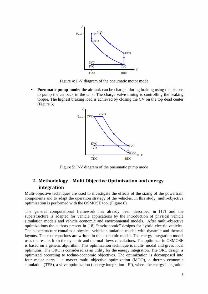
• Pneumatic pump mode: the air tank can be charged during braking using the pistons to pump the air back in the tank. The charge valve timing is controlling the braking torque. The highest braking load is achieved by closing the CV on the top dead center (Figure 5)
Figure 5: P-V diagram of the pneumatic pump mode
2. Methodology – Multi Objective Optimization and energy
integration
Multi-objective techniques are used to investigate the effects of the sizing of the powertrain components and to adapt the operation strategy of the vehicles. In this study, multi-objective optimization is performed with the OSMOSE tool (Figure 6).
The general computational framework has already been described in [17] and the superstructure is adapted for vehicle applications by the introduction of physical vehicle simulation models and vehicle economic and environmental models. After multi-objective optimizations the authors present in [18] “environomic” designs for hybrid electric vehicles. The superstructure contains a physical vehicle simulation model, with dynamic and thermal layouts. The cost equations are written in the economic model. The energy integration model uses the results from the dynamic and thermal flows calculations. The optimizer in OSMOSE is based on a genetic algorithm. This optimization technique is multi- modal and gives local optimums. The ORC is considered as an utility for the energy integration. The ORC design is optimized according to techno-economic objectives. The optimization is decomposed into four major parts – a master multi objective optimization (MOO), a thermo economic simulation (TES), a slave optimization ( energy integration - EI), where the energy integration

7
occurs. The last part is the techno-economic evaluation (TEE). Appendix 2 describes the main steps.
Figure 6: General computational framework – OSMOSE and multi periods
In this article the slave optimization (Figure 7) is applied for the ORC utility sizing.
The utility system pertinent for energy recovery - the organic rankine cycle (ORC) (Figure 8) is defined in the energy integration module. In the EI the level of temperatures (evaporation and superheating) of the ORC are optimized to obtain the maximal net power output. The optimization is done for each operating point and each working fluid and comfort demand. The outcomes of this optimization are the ORC loop sizing (working fluid flow, sizes of the turbo machines and exchanged heat in the evaporation and the condensation) the efficiency and the net power output.

8
Figure 7: Energy integration and multi- periods approach
The ORC is presented in Figure 9.
Figure 8: Organic Rankine cycle installation
In this article the energy integration methodology is applied on the vehicle powertrain and the cabin.The techno-economic evaluation of the hybrid pneumatic powertrain in combination with the energy recovery technology is tested on different driving profiles – NEDC, urban, peri-urban and long way drives.

9
3. Hybrid Pneumatic Powertrain concept and modelisation
3.1 Simulation model
The hybrid pneumatic powertrain has 3 modes: thermal traction with torque generation in conventional combustion mode, pneumatic traction with torque generation in pneumatic motor mode, regenerative braking with torque recuperation in pneumatic pump mode. Unlike with the parallel thermal electric, the two energy sources never operate simultaneously. The modeled engine is a 1.2l NA gasoline engine, 60 kW, operating on 4 strokes. Fuel is cut off during the pneumatic modes. No supercharging or undercharging modes are considered. For low complexity and low cost reasons, the mechanical valve train from the original engine is conserved and the CV is assumed to be electromagnetic. The hybrid pneumatic gasoline engine is integrated in a C- Segment vehicle [19]. To give flexibility of the model for optimization approaches, the original manual gear box (MGB) is replaced by a continuously variable transmission (CVT). The advantage of the CVT is to adapt the gear ratio to any drive cycle and additional modeled technology – for example a utility for waste heat recovery. The powertrain model is enough flexible and simplified to suit in the future for an optimization study. The model flowchart is presented in the Figure 9:
Figure 9: Hybrid pneumatic engine model flowchart
The three engine operating modes are represented in the engine bloc. The combustion and the pneumatic modes are described by maps. The pneumatic maps are results from simulations. These maps consider the kinematics of the air transfer through the engine, the charge valve timing and the exchanged heat between the pistons and the cylinder wall.

10
The model uses a mode strategy to determine the optimal operating mode between pneumatic motor mode and combustion mode.
The model of the air tank computes the tank temperature and pressure from the air flow rate airm& and the enthalpy flow rateairh& . The following equations are used in the model:
- Ideal gas law k
airairairair V
TrmP
tan
**= (1)
- Energy balance of the tank int, *)(* φ+= hdt
dTTcm airvair
& (2)
- Heat flux between the air and the inner wall )(*intint airwallcyl TTAh −=φ (3)
- Tank wall energy balance dt
dTcm wall
wallpwallext ** ,int =− φφ (4)
- Heat flux between air and outer tank wall )(** wallextcylextext TTAh −=φ (5)
Where airT , wallT , extT are respectively the air temperature inside the tank, the tank wall temperature and the ambient air temperature. airm and wallm are the masses of air inside the tank and near the wall. airr is the specific gas constant, airpc , is the specific heat capacity of the air,
airvc , is the volumetric heat capacity of the air. wallpc , is the specific heat capacity of the wall.
inth is the heat transfer coefficient between the inner wall of the tank and the air inside the tank.
The air tank is a stainless steel, and it is a cylinder with a radius 3 times smaller than its length. The air temperature in the tank is homogeneous. The admissible pressure is between
barP 5min = and barP 20max = . The admissible temperature is between 300 K and 1000 K. These limits come from the ranges of the pneumatic pump and motor maps. The CVT chooses the optimal powertrain efficiency taking into account the combustion and the pneumatic modes. For combustion mode the selected gear ratio gives the minimal fuel consumption on the iso-power. For pneumatic modes the selected ratio allows maximum charging for the air tank and maximal torque for the pneumatic motor.
Table 1 sums the vehicle characteristics for simulation:
Table 1 : C segment vehicle characteristics for simulation
Sub-System Characteristic Value
Vehicle Nominal mass [kg] 1075
Gear box CVT efficiency [-][20] 0.84
MGB efficiency [-] 0.95
Engine Displacement [l] 1.2
Number of cylinder 3
Rated power [kW] 60
Max. speed [rpm] 6000
Max. Torque [Nm] 120
Idle speed [rpm] 950
Idle fuel consumption [l/h] 0.33
Deceleration Fuel cut- off Yes
Fuel Type Gasoline
Density [kg/l] 0.795
Lower heating value [MJ/kg] 42.7
Pneumatic Motor Minimum speed [rpm] 200
and Pump Maximum speed [rpm] 3000
Air tank Volume [l] 50
Steel wall thickness [mm] 4

11
wallpc , [J/kgK] 5
inth [W/m²K] 5
outh [W/m²K] 5
Minimum pressure [bar] 5
Maximum pressure [bar] 20
Initial pressure [bar] 4
Initial temperature [°C] 25
Ambient air Temperature [°C] 25
3.2 Economic model:
The commercial cost for the based vehicle, called car shell, is evaluated from the website in [21]. We consider a serial C-Segment vehicle, with a 1.2l gasoline engine developing 60 kW. It is also using an automatic gearbox.
Cost���_��� = 23400 [in Euros] The cost of the hybrid pneumatic powertrain is estimated to 6100 euros.
The total price of the ORC is used, thus only the investment cost is taken into account. The operating cost is deduced after the best design definition of the ORC. The investment cost of the ORC is a linear function which takes into account the large units volume, adapted for the automotive industry. The investment cost is the sum of the following equations:
84.18*49.14 += evaporatorevaporator AreaCost [in Euros, Area in m²] (6)
96.4*01.4 += condensercondenser AreaCost [in Euros, Area in m²] (7) 165*083.0 += flowrateCostpump [in Euros, flowrate in kg.s-1] (8)
30*015.0 −= turbineturbine PowerCost [in Euros, Power in kW] (9) 26=pipeCost [in Euros] (10)
10=fluidCost [in Euros] (11)
pipesfluidturbinepumpcondenserevaporatorORC CostCostCostCostCostCostCost +++++= [in Euros] (12)
The vehicle cost is expressed by the following equation: ����������� = �������� ! "�# + ����%&' + �����" _(���� in Euros (13) The vehicle also benefit from governmental grant of 4300 euros because it emits less than 60g.km-1 [21]. The vehicle cost is expressed by the following equation: ����������� = �����#�)*"!������ ! "�# + ����%&' + �����" (���� − ,-./�'%0[in Euros] (14)
All costs are calculated in Euros.
4. Results
4.1 Multi-objective Optimization – sizing of the ORC installation:
The design criteria of the ORC loop are defined bellow.
Performances:

12
• The net power in kW is the absolute value of the mechanical power, delivered by the work cycle.
The net power of the ORC is to be maximized. The maximum net power output is not corresponding always to the maximum available exergy. So one prefers to maximize the net power output, with a constraint for the exergy efficiency – it should be higher than 20%. The performance indicator is defined in the next equation:
pumpingansionnet PPP &&& −= exp (15)
• Economic: The investment cost of the ORC is defined by the equation (16):
fluidepipesturbinecompressorevaporatorcondenserORC CostCostCostCostCostCostCost ++++= + (16)
Decision variables:
One needs to choose the variables for the ORC design. It is a system with two degrees of freedom:
• The evaporation temperature of the fluid – evapT . The range is defined between 330 K
and 360 K and is constraint by enough good values of the exergetic efficiency. • The superheat temperature - erheatingTsup [700-1050] K
The optimization function of the ORC design is defined as:
)),(),(min( xCostxP ORCnet&− with )var_( iablesdecisionXx∈ (17)
As a first step of the design process a sensitivity analysis of the ORC net power output is performed as a function of the ORC evaporation and superheating temperatures. The sensitivity analysis helps to define the ranges of the decision variables (Figure 11).
Figure 10: Net power output in kW as a function of the ORC evaporation and ORC superheating for 1.2 NA gasoline engine, with Ammonia as working fluid
Net Power
[kW]

13
The net power evolution on the superheating temperature seems to be a second order, whereas the net power evolution on the evaporation temperature is a first order evolution. For a given superheating temperature, it seems that the best temperature is around 355 K. For an evaporation temperature superior to 360 K, the efficiency is much lower due to the pinch point is out of the self-sufficient pocket. For a given evaporation temperature, the net output power is slightly better for high superheating temperatures. Other characteristic is that without superheating the exergetic efficiency decreases. The maximum for the evaporation temperature is 355 K and for a realistic design corresponding on the heat sources onboard, the superheat temperature is limiter to around 1000 K.
Pareto-curves:
The multi-objective optimization problem converges on the following Pareto curve. The Pareto illustrates the trade-off between the ORC net power and the investment cost. The solutions are summarized in two Pareto Fronts, with a total investment cost between 350 and 700 euros.
Figure 11: ORC Pareto curves, gasoline engine high speed, and high load operating point
Figure 12: Cost distribution of different ORC designs, points 1, 2 and 3 (Figure 11)
Points 1 or 2 represent same cost designs for different net output power. Point 2 and 3 represent same net output power designs for different cost. Point 2 (middle on that figure) is the reference one, efficient for a reasonable cost. The design in point 2 presents a compromise between the evaporator area and the pump size. The difference between the first and the second solution is significant. The pump is overdesign, whereas the turbine is rather small: in point 2 a powerful pump is used and the fluid flow is increased, so the evaporation area
1
2 3
Exergetic efficiency [-]
Exergetic efficiency [-]

14
decreases. It can be seen on the T-s diagram that the difference between the condensation and evaporation temperature is much more important thanks to the pump.
The total techno- economic performances for these three designs are summarized in table 2.
Table 2: techno –economic performances of different ORC design
Figure 13: T-S Diagram comparison between point 1 (green) and point 2 (blue), with ammonia saturation curves (black)
The design from point 2 is operating at high flow rate, but really small difference between the evaporation temperature and the condensation temperature, it explains why the efficiency on this part of the Pareto line corresponds to inefficient designs. The situation is more balanced between point 1 and point 3, but still the pump cost ratio is bigger than the reference case.
ORC Loop design and optimization:
The solutions from the first Pareto Front are more interesting for the ORC design. The best compromise is not obvious to find and a utility function is introduced to classify the solutions as a function of the performance or the economic advantages.
0,))()(
)((*)
)()(
)((*)( 22 >
−−+
−−−= jjjjj ba
PowerMinPowerMax
PowerPowerMaxb
CostMinCostMax
CostMinCostaiutility (18)
The function between the cost and the net power is convex and gives the compromises between the performances indicators. If just one of the indicators is considered, the penalty due to the second one is high, because the term is on square. Thus a balance situation is preferred. Different set-up of the coefficients a and b is possible:
• Economic: only the cost is taken into account, 10 =a and 00 =b
Design Type Inside Middle Outside
Price [Euros] 522.9 514.1 700.9
Power [kW] 2.56 10.07 10.61
Specific entropy

15
• Efficiency: only the net power is considered, 01 =a and 11 =b
• Balanced: the two objectives are considered with the same weight 11 =a and 11 =b
The Pareto is after treated on the following way and the utility functions are illustrated in the Figure 14:
(a)
(b)

16
(c )
Figure 14: Convergence of three ORC parameters design for a gasoline engine – a) compressor power, b) heat exchangers size, c) flow rate
For each parameter the best Pareto point is obtained at the maximum of the x-axe. For the balance curve the best 10% of the optimum function are reached for a narrow vicinity of the best parameters. There is only one configuration which can be considered among the best ones. The best design is completely different for the economic and the performance utility function. The economic optimum has the smallest heat exchangers and the smallest compressor, thus has small net power performance. The opposite occurs with the net power performance curve. The balanced design solutions are relatively close to the performance design.
The best techno – economic design for the ORC adapted to a gasoline engine has the next parameters for the operation point – 5500 rpm 11.15 bar:
• Condenser area: 4.1 m² • Evaporator area: 0.83 m2 • Compressor power: 0.18 kW • Ammonia flow rate: 3.4 g.s-1 • Turbine power: 11.52 kW • Estimated Cost ORC: 539 Euros
The best techno-economic design is obtained for a high speed; high load operating point and then this design has to be extended on the engine operating field. The gasoline engine has two heat sources – the cooling water circuit and the exhaust gases.
Over the engine operating field on can distinct three situations:
• The heat sources enable the working fluid to reach a superheating temperature. The problem can be solved with a system of non-linear equations:

17
−=
−=
−−
−−−=
)(**
)(**
))(
)(ln(
)()((**
sup__
sup
sup
nevaporatioerheatfluidworkingfluidworking
coolingexhaustexhaustexhaust
nevaporatiocooling
erheatexhaust
nevaporatiocoolingerheatexhaust
TTcpmQ
TTcpmQ
TT
TT
TTTTAUQ
&
&
, (19), (20), (21)
where U is the thermal exchange coefficient of the heat exchanger, A is the heat exchanger area, and Q is the exchanged power. This system should be solved to get the exchanged power for each operating point, knowing the heat exchanger and engine characteristics. The system is linearized to be solved:
(22),(23),
(24),(25)
• If part of the evaporator of the exhaust gases is used to evaporate with the water circuit, the evaporator area is reduced. The amount of power to finish the evaporation is calculated and the needed evaporator area is deduced from the previous equations. The superheating temperature, the cooling temperature and the exchanged power are calculated from the previous equations.
=
=
−
+
=
=
= −
fluidworkingpfluidworkin
pexhaust
mcmAU
evap
exhaust
nevaporatioexhaust
erheating
cooling
cm
cmM
e
T
T
TT
b
T
T
Q
X
with
bAX
fluidpcexhaustfluidworkingpfluidworking
___
)1
*
1(**
sup
1
*
1
*
1
0
_,
*
*
_*___
&
&
&
αα

18
• If there is not enough energy to reach a superheating temperature, then one can compute the exchanged power, by using the evaporation enthalpy of the working fluid and the linear equations.
After that, knowing the temperatures and the exchanged power, it is possible to compute the power maps, the energy efficiency and the exergetic efficiency maps of the gasoline engine (Figure 15).
Figure 15: Net output power map of ORC, optimized design, on the engine field
The maximum net power output is reached over the engine iso-line of 30 kW – this means for high rotation speeds and loads. The optimization of the ORC design is done for the loaded points. The motivation for that is that this is also the region with the most important heat losses. This design is extended on the engine operating field and one considers that the pump operates with permanent parameters.
4.2 Simulations results on driving cycles:
This study extends the optimization methodology for vehicle energy systems design on other drive cycles. The urban and peri- urban cycles represent the home to work commuting usage and the holiday cycle is representative for long distances drive. Table 3 summarizes their characteristics: Table 3: Drive cycles characteristics
Cycle Distance (km) Duration (s) Average speed (km/h)
Min acceleration (m/s²)
Max acceleration (m/s²)
NEDC 11.023 1180 32.26 Urban 8.5 1644 18.8 -1.5 1.7 Peri- Urban 39 2440 57 -2 2 Holiday 847 28800 (8h) 105 -1.9 1.9

19
The urban and peri-urban cycles are based on the urban and peri-urban parts of the WLTP cycle. The cycles are illustrated in Appendix 1.
4.2.1 Comparison of different configurations
Thanks to the ORC heat recovery the gasoline engine in the hybrid pneumatic powertrain obtains also an additional flow of mechanical power. The hybrid pneumatic powertrain has already a pneumatic energy recovery system. This type of recovery system is short term storage and is very efficient for low speed drives, where the power delivered by the pneumatic stocker is sufficient to drive the pistons, without fuel injection. The proposed ORC design is optimized for high rotation speeds and high loads, which is a complementary zone, where the pneumatic powertrain is inefficient. The results from the simulations are summarized in the Table 4.
Table 4: Driving cycles and fuel consumption results on C-Segment Vehicle
Driving Cycle Propulsion Type Fuel consumption [l/100 km]
Emissions [g CO2/ km]
Powertrain Efficiency gain [%]
1.2 4.72 108 - 1.2 HPP 4.16 96 10.8 NEDC 1.2 ORC 3.71 85 24 1.2 ORC HPP 3.32 77 38.4 1.2 4.72 108 - Urban 1.2 HPP 2.25 51.93 109 1.2 ORC 3.00 92 17.9 1.2 ORC HPP 2.22 51 112.2 1.2 5.56 127 - 1.2 HPP 5.05 116.27 10 Peri Urban 1.2 ORC 4.14 95 34.2 1.2 ORC HPP 3.98 91 39.7 1.2 5.94 137 - 1.2 HPP 5.86 134.88 1.3 Holidays 1.2 ORC 4.27 98 38.9 1.2 ORC HPP 4.35 100 36.2
The simulation result on NEDC of the fuel consumption for the baseline vehicle – 1.2l NA gasoline engine is 4.6 l/100 km. As discussed previously in part 3 the fuel consumption result from the model is underestimated with 7% in comparison to the commercial baseline vehicle which targets on 5 l/100 km and 114 g CO2/km. One has to consider this fact for the presented fuel consumption estimations. All results presented in table 5 are coming from simulations with the same vehicle model, so the relative values of the fuel improvement due to the powertrain efficiency increase are correct. The technological options such as the hybrid pneumatic powertrain and the organic rankine cycle do not exist on serial vehicles. The research and the automotive engineering study them. Thus the simulation approach is an interesting one for the first techno-economic performances assessments. The simulation study is done for a baseline C-Segment vehicle with a mass of 1075 kg and small 1.2 NA gasoline engine of 60kW. The mass of 1075 kg is one of the lowest values for this segment and results from a lot of efforts of vehicle lightening. The mass is an important factor for the fuel consumption. A second point to be noted for the baseline vehicle is the efficiency of the small 1.2 l NA gasoline engine. This engine is downsized and optimized from architecture and functional point of view. Thus the combination of the downsized engine with the vehicle optimized mass of 1075 kg presents a good adaptation and allow to the engine to be well charged and used in its best efficiency zones. Figure 16 illustrates the repartition of the

20
operating points on the engine field on the NEDC and the vehicle of 1075 kg of nominal mass and manual gear box.
Figure 16: repartition of the operating points on the engine field – NEDC, manual gear box
Even if the urban cycle is characterized with a lot of transients (Figure A.1) and low average speed (Table 4) the engine in combination with the CVT is well used and the CO2 emission are equivalent to the NEDC cycle with manual gear box – 108 g CO2 /100 km. The peri-urban and holiday cycle are characterized by higher average speed (Table 4) and longer distance drives (Figure A.2). Thus the engine is charged considerably and the obtained fuel consumption with a CVT is 5.56 l/100 km for the peri-urban cycle and 5.94 l/100 km for the holiday cycle.
The introduction of the hybrid pneumatic powertrain (HPP) on the baseline vehicle definition improves the powertrain efficiency with 11% on NEDC, 10% on the peri-urban cycle, and just 1.3% on holiday cycle. First the effect of pneumatic powertrain is clear: the powertrain efficiency is improved by more than 100% on the urban drive. There the fuel consumption is reduced by around 2 to less than 2.5 l/100 and the CO2 emission are reduced till 52 g CO2/ km, which is very low emissions value. The HPP efficiency improvement on urban drive is impressive but its range is limited and on holiday cycle the contribution is around 1%.
The HPP is a short term storage system characterized with high power density and low energy density. Thus the HPP is most efficient for the urban cycle characterized by acceleration and deceleration transient and low engine power demands. The efficiency improvement of the HPP decreases on the NEDC and the Peri –urban cycles, because these cycles except the urban part, have also a large extra urban part, which is more energy demanding and where the HPP mode is not active. On the holiday cycle, except for the urban part of the beginning the HPP is not used. One can conclude that the HPP is an efficient technology for the city drive and can be consider as a non-electric alternative of the mild hybrid electric vehicle.
The ORC design proposed for the ORC net power map of the Figure 17 is optimized for high load and high speed engines operating points, where the waste heat recovery potential essentially due to the high temperature exhaust gases is important. The selected ORC design is evaluated on the different driving cycles. At first just the ORC contribution is considered. From the results is Table 5 one can see that on the combined cycles (with urban and extra urban part) – NEDC and peri-urban the efficiency improvement is 24% and 34%. The ORC is efficiently used in the charged part of the cycles. The lowest potential of the ORC is obtained

21
for the urban cycle – 17% improvement, where the ORC is used in low power demands and thus lower net power ORC zones. The improvement potential on holiday cycle is around 40% and the fuel consumption passes below 4.5 l/km. Thus one can conclude that the selected ORC design is an efficient technology for a waste heat recovery in the high speed demanding drives with high engine power demand.
As a next step it is interesting to analyze the combination of the HPP and the ORC. For the combined cycles the combination of a HPP and ORC on a small downsized engine brings the best fuel saving potential – around 40%. The HPP contributes to the efficiency improvement on the urban drives and the ORC on the extra-urban drives. On the urban drive the combination of the both options is not effective because the major part of the gain is due to the HPP. The result is on the opposite for the holiday cycle, where the ORC contributes for the major part of the improvement.
One can conclude that the combination of a short term storage technology as the hybrid pneumatic powertrain and a waste heat recovery technology as the organic rankine cycle is efficient for combined usages of the vehicle. The C-Segment vehicle is a category that can be used for daily home to work commuting and also for family or business long ways drives. For the C-Segment vehicle the combination of the both energy recovery options is efficient and the powertrain efficiency optimization for NEDC is of around 40%. The vehicle emissions are low – 77 g CO2 /km. Thus the customer can benefit from environmental bonus on the vehicle price. For the studies case and for vehicle usage in France, the grant for the customer could be around 4300 €.
4.2.2 Economic impacts:
Different technological options of the powertrain of the C-Segment vehicle are compared according to the required investment and operating costs. The operating cost is calculated based on a 150000 kilometers and NEDC. The actualization of the cost is defined on 10 years investment basis, using an actualization rate of 4%.
Than the yearly annualized cost (YAC) is computed for different vehicles, according to the formula:
YAC = OPEXn
+ CAPEX * τ
τ = i *(1 + i )n
(1+ i )n −1,i = 0.04,n = 10
(26), (27)
with OPEX- operating cost, CAPEX the investment price, i the actualization rate (0.04%, n the investment time (10 years).
So the annualized cost is computed for different vehicles and summarized in table 5:
Table 5: CAPEX, OPEX, yearly annualized cost (YAC) for different C-Segment vehicle versions for NEDC
Vehicle type CAPEX OPEX YAC C-Segment 1.2 27700 12442 4659 C-Segment 1.2 HPP 33450 11234 5247 C-Segment 1.2 ORC 27889 10034 4441 C-Segment 1.2 ORC HPP 30039 8987 4602

22
According to the results on NEDC, the powertrain definition with lowest YAC for normalized use case is the 1.2 ORC. NEDC combines urban and extra urban part, where the ORC brings fuel large consumption benefit - 13% for an investment of 539 euros. The ORC loop is optimized for the loaded zone of the engine operating field.
The peri-urban cycle brings the same compromise.
As the hybrid pneumatic powertrain technology presents its major interest on urban drives, the economic study is also performed for the urban cycle and the results are rather different (Table 6):
Table 6: CAPEX, OPEX, yearly annualized cost (YAC) for different powertrain versions for urban cycle
Vehicle type CAPEX OPEX YAC C-Segment 1.2 27700 12753 4690 C-Segment 1.2 HPP 33450 6075 4735 C-Segment 1.2 ORC 27889 10818 4520 C-Segment 1.2 ORC HPP 30039 6011 4311
For the urban cycle, the efficiency advantage of the hybrid pneumatic powertrain is well recognized and the combination with the ORC seems to bring the best fuel economy potential and economic exploitation, even if the technological investment is the highest one. For urban drives the best YAC results are obtained for vehicle powertrain definition with the highest hybridization ratio.
Finally the combination of the ORC and hybrid pneumatic powertrain seems to be the most efficient and performing for all cycles, with more than 25% fuel consumption improvement. The holiday cycle shows that the ORC has a big interest for the highway consumption and during long drives. The gasoline engine is a small engine and operates on loaded points with the C-Segment vehicle. The downsizing combines well with the heat recovery. For the gasoline hybrid pneumatic powertrain, the ORC cycle has been design to be efficient for loaded points, such as highway driving and still reach 24% for NEDC. A main asset for the ORC is that cover a large range of usages – urban, peri-urban and long way drives, which is not usually reached by the conventional hybrid technology. Thus, associating ORC with another hybrid system, efficient mainly during urban driving, enables to save fuel on the whole driving spectrum.
The cost of the ORC with the proposed design is assessed on around 600 euros and this order of magnitude makes it realistic solution, as it is also the most economical solution for the annualized cost.
The articles illustrated a method to select the most adapted design and use a customer profile method to illustrate the best usages of the ORC in combination with an alternative hybrid. The benefit of the combined energy recovery shows encouraging results. The customer can obtain low CO2 emission technology for an investment between 27900 and 34000 €. The annualized cost of the mobility is also competitive for the different drives:

23
Figure 17: economic indicators for the HPP and ORC powertrain for NEDC and urban cycles
5. Conclusion:
This article presents a study of the efficiency performance and the economic optimization for a C-Segment vehicle with a small downsized gasoline engine. Two technological options are studied for the efficiency improvement of the baseline vehicle powertrain:
• Short term pneumatic energy storage – called hybrid pneumatic powertrain • Waste heat recovery system for two heat sources the engine water circuit and the
exhaust gases – organic rankine cycle
As these technologies are not in a serial production in the automotive industry, the simulation model and the hybrid pneumatic powertrain are introduced. The ORC design is optimized for high load and high speed engine operating conditions. The design is optimized according to techno- economic performances indicators. To do that a multi-objective optimization methodology is applied in combination with the integration of the energy integration. An innovative methodology for the design selection considering the performances and the cost of the ORC is also illustrated.
The technological options are evaluated separately but also in combination on different driving cycles. The NEDC is selected for giving the reference but also for correlation with the baseline definition of the vehicle. The urban, peri-urban and holiday cycles are introduced for more representative customers drives but also to test the robustness of the fuel saving potential on a real drives representative cycles.
The main conclusion coming from the driving cycles evaluation is the short term energy storage is an efficient technology for the urban drive and brigs more than 100% improvement of the powertrain efficiency on the given urban profile. The customer investment is 33450 euros. The selected ORC design is efficient on the extra urban part of the cycles and the holiday cycle, where the small gasoline engine is highly charges, because of the high power vehicle demands. The best improvement potential of the ORC is calculated for the peri-urban and the holiday cycles and is around 40%. The HPP and the ORC are complementary technologies and their combination is especially efficient on the combined cycles – with urban and extra urban part. The result of 77 g CO2 /km obtained for the combined powertrain on NEDC gives an advantage to the customer to receive an environmental grant of 4300 € on the
C-Segment 1.2l ORC HPP urban
C-Segment 1.2l ORC HPP NEDC0
10000
20000
30000
40000
CAPEXOPEX
YAC
30039
6011
4311
30039
8987
4602
Eu
ros

24
vehicle price. The yearly annualized cost for mobility with a powertrain combining a HPP and ORC is 4602 € (for NEDC).
Appendix 1:
Urban cycle:
Figure A.1: urban speed profile
Peri- urban cycle:
Figure A.2: Peri- urban speed profile

25
Appendix 2:
Master Optimization: The set of decision variables includes the types and the size of the equipment. The master optimization is solved by an evolutionary algorithm (EMOO) with 2 objectives: the minimization of the fuel consumption, the minimization of the investment cost for the technologies (Figure 8).
Thermo-economic simulation: in a second step the thermodynamic and economic state of the selected equipment is calculated by using a thermo-economic simulation models.
Economic evaluation: the selected superstructure in the master level and the result of the slave optimization are used in the techno-economic evaluation (TEE) phase to calculate objective functions of the master optimization – cost, and CO2 emission. The multi-objective optimization results converged to the Pareto frontier curve.
Slave optimization: The energy integration calculates the best operating strategy of selected equipment by solving a mixed integer linear model (MILP) (Figure 8). The aim is to minimize the total cost under the energy balance and the heat and power cascade constraints. The input data used in the energy integration includes the values of the master decision variables, the resources, the power dynamic profile and the comfort profile.
The energy integration is done in the second stage of the approach and this is a slave optimization based on mixed integer linear programming. The energy integration defines the potential of heat recovery and deduces the choice and the sizing of the adapted utilities. In the energy integration problem the engine and the vehicle cabin are defined as processes “cold” and “hot” streams between which a heat exchange has to occur. The minimum energy requirement of the system is then estimated and a utility is used to close the energy balance and estimate the energy recovery potential. These steps of the algorithms will be exposed in the section results.
Acknowledgments
The authors would like to thank EPFL for the research conditions.
References
[1] C. Thiel, J. Schmidt, A. Van Zyl, E. Schmid, Cost and well-to-wheel implications of the vehicle fleet CO2 emission regulation in the European Union, Transportation Research Part A: Policy and Practice, Volume 63, May 2014, Pages 25-42 [2] L. Damiani, M. Repetto, A. Pini Prato, Improvement of powertrain efficiency through energy breakdown analysis, Applied Energy, Volume 121, 15 May 2014, Pages 252-263 [3] L. Torres, R. Gonzalez, A. Gimenez, J. Lopez, Energy management strategy for plug-in hybrid electric vehicles. A comparative study, Applied Energy, Volume 113, January 2014, Pages 816-824 [4] Justin D.K. Bishop, Niall P.D. Martin, Adam M. Boies, Cost-effectiveness of alternative powertrains for reduced energy use and CO2 emissions in passenger vehicles, Applied Energy, Volume 124, 1 July 2014, Pages 44-61 [5] L. Guzzella, A. Scarletta, Vehicle Propulsion Systems – 2013, Springer

26
[6]GuzellaResearch,http://www.idsc.ethz.ch/Research_Guzzella/Automotive_Applications/Hybrid_Pneumatic_Powertrain, accessed on 23.09.14 [7] Z. Filipi Hydraulic and pneumatic hybrid powertrains for improved fuel economy in vehicles, Alternative Fuels and Advanced Vehicle Technologies for Improved Environmental Performance (2014), 505-540 [8] K. David Huang, Sheng-Chung Tzeng - Development of a hybrid pneumatic-power vehicle Applied Energy (2005), Volume 80, 47-59 [9] K. David Huang, Sheng-Chung Tzeng, Wei-Chuan Chang, Energy-saving hybrid vehicle using a pneumatic-power system, Applied Energy (2005), Volume 81, 1-18 [10] T.L. Brown, V.P. Atluri, J.P. Schmiedeler A low-cost hybrid drivetrain concept based on compressed air energy storage, Applied Energy (2014), Volume 134, 477-489 [11] U. Spicher, 2012, Analysis of the efficiency of future powertrains for individual mobility, MTZ 02/2012, volume 73 [12] Z. Dimitrova, F. Maréchal, Energy integration on multi-periods and multi-usages for hybrid electric and thermal powertrains, Energy, http://dx.doi.org/10.1016/j.energy.2015.02.060. [13] S. Fazlollahi, F. Maréchal, Multi-objective, multi-period optimization of biomass conversion technologies using evolutionary algorithms and mixed integer linear programming (MILP), Applied thermal engineering, 50 (2013) 1504- 1513 [14] L. Gerber, F. Maréchal - Environomic optimal configurations of geothermal energy conversion systems: Application to the future construction of Enhanced Geothermal Systems in Switzerland, Energy (45), 2012, 908-923, [15] L. Tock, F. Maréchal - Process design optimization strategy to develop energy and cost correlations of CO2 capture processes, Computers and Chemical Engineering 61 (2014) 51– 58. [16] E. Peduzzi, L. Tock, G. Boissonet, F. Maréchal- Thermo-economic evaluation and optimization of the thermo-chemical conversion of biomass into methanol, Energy 58 (2013) 9-16 [17] Z. Dimitrova, F. Maréchal, Environomic design of vehicle integrated energy systems- application on a hybrid electric vehicle energy system, CET, volume 39, 2014, p. 475-480, DOI:10.3303/CET1439080 [18] Z. Dimitrova, F. Maréchal, Environomic design of vehicle energy systems for optimal mobility service, Energy (2014), Volume 76, 1019-1028 [19] Peugeot car configurator, http://configurer.peugeot.fr/configurer/nouvelle-308/5-portes, accessed on 23.01.15 [20] CVT Nissan technology http://www.nissanglobal.com/EN/TECHNOLOGY/OVERVIEW/cvt.html, accessed on 20.10.14 [21] Décret n° 2007-1873 du 26 décembre 2007 instituant une aide à l'acquisition des véhicules propres, http://www.legifrance.gouv.fr/, accessed on 23.01.15