Performance analysis of D-STATCOM with …...Performance analysis of D-STATCOM with Consideration of...
5
International Journal of Scientific & Engineering Research, Volume 6, Issue 8, August-2015 1787 ISSN 2229-5518 IJSER © 2015 http://www.ijser.org Performance analysis of D-STATCOM with Consideration of Power Factor Correction M.Bala krishna Naik 1 I.Murali krishna 2 Dr K.Satya Narayana 3 M .Tech in pragati engg college Asst prof in pragati engg college Professor & HOD in pragati engg college bala [email protected] [email protected] [email protected] Abstract- In this paper proposes an intelligent approach (Fuzzy logic) for the design of PI controller for power. D- STATCOM for power factor and harmonic compensation. The proposed control strategy has been introduced in order to enhance some steady-state performances besides its functional elimination of power quality disturbances. Power factor and harmonic current of a controlled feeder section are two vital roles in steady-state power distribution system operation. Utilizing an already installed D-STATCOM to achieve these additional control objectives can help system operators maximize overall system performances. In this paper, a control scheme with constant power and sinusoidal current compensation [1,2] is exploited. In order to correct the power factor, a power factor control loop is required and therefore included in the control block. To verify its use, a 22-kV power distribution feeder with a three-phase rectifier load was tested. Resultsshowed that integration of the proposed reactive power control loop can correct the power factor of the controlled feeder to be unity power factor. 1. INTRODUCTION Electric power distribution network have become more increasingly important and plays an essential role in power system planning. This type of power systems has a major function to serve distributed customer loads along a feeder line, therefore under competitive environment of electricity market service of electric energy transfer must not be terrupted and at the same time there must provide reliable, stable and high quality of electric power [2-3]. To complete this challenge, it requires careful design for power network planning. There exist many different ways to do so. However, one might consider an additional device to be installed somewhere in the network. Such devices are one of Capacitor bank, shunt reactor, series reactors, automatic voltage regulators and/or recently developed dynamic voltage restorers, distribution static compensator (DSTATCOM),or combination of them [4-7]. The DSTATCOM [8-10] is a voltage source converter (VSC) based custom power technology which can perform as a reactive power source in power systems. The D-STATCOM can Regulate magnitude of voltage at a particular AC bus, at the point where it is connected, via generating or absorbing reactive power from the system. From D-STATCOM literature, a majority of research works have been conducted in order to enhance electric power quality due to distribution voltage variations, e.g. voltage sags or swells. Apart from these voltage variations, the D- STATCOM is capable to enhance steady-state Performances such as power factor and harmonic of a particular feeder portion. In this paper, a control scheme with constant power and sinusoidal current compensation [1] is exploited. In order to correct the power factor additionally, a power factor control loop is required and therefore included in the control block. II.DESCRIPTION OF D-STATCOM OPERATION A D-STATCOM is a shunt device that regulates the system voltage by absorbing or generating reactive power at a point of coupling connection. The schematic diagram of a DSTATCOM is shown in Fig 1. The D- STATCOM is a solid state DC/AC power switching converter that consists mainly of a three-phase PWM voltage source converter (VSC) bridge having six IGBTs with associated anti-parallel diodes. It is connected to the distribution network via the impedance of the Coupling transformer. A DC-link capacitor provides constant DC link voltage. Fig. 1. Simplified power system equipped with a D- STATCOM The output voltage of the D-STATCOM is generated by a DC/AC voltage source converter operated from an energy storage capacitor. From the DC input voltage provided by a charged capacitor, the converter produces a set of controllable three-phase output voltages at the frequency of the AC power system. Each output voltage is in phase with and coupled to the corresponding AC voltage via coupling reactance. By varying the magnitude of output voltage produced, the IJSER
Transcript of Performance analysis of D-STATCOM with …...Performance analysis of D-STATCOM with Consideration of...
International Journal of Scientific & Engineering Research, Volume 6, Issue 8, August-2015 1787 ISSN 2229-5518
IJSER © 2015 http://www.ijser.org
Performance analysis of D-STATCOM with Consideration of Power Factor
Correction
M.Bala krishna Naik1 I.Murali krishna2 Dr K.Satya Narayana3 M .Tech in pragati engg college Asst prof in pragati engg college Professor & HOD in pragati engg college bala [email protected] [email protected] [email protected]
Abstract- In this paper proposes an intelligent approach (Fuzzy logic) for the design of PI controller for power. D-
STATCOM for power factor and harmonic compensation. The proposed control strategy has been introduced in order to
enhance some steady-state performances besides its functional elimination of power quality disturbances. Power factor
and harmonic current of a controlled feeder section are two vital roles in steady-state power distribution system operation.
Utilizing an already installed D-STATCOM to achieve these additional control objectives can help system operators
maximize overall system performances. In this paper, a control scheme with constant power and sinusoidal current
compensation [1,2] is exploited. In order to correct the power factor, a power factor control loop is required and therefore
included in the control block. To verify its use, a 22-kV power distribution feeder with a three-phase rectifier load was
tested. Resultsshowed that integration of the proposed reactive power control loop can correct the power factor of the
controlled feeder to be unity power factor.
1. INTRODUCTION Electric power distribution network have become more increasingly important and plays an essential role in power system planning. This type of power systems has a major function to serve distributed customer loads along a feeder line, therefore under competitive environment of electricity market service of electric energy transfer must not be terrupted and at the same time there must provide reliable, stable and high quality of electric power [2-3]. To complete this challenge, it requires careful design for power network planning. There exist many different ways to do so. However, one might consider an additional device to be installed somewhere in the network. Such devices are one of Capacitor bank, shunt reactor, series reactors, automatic voltage regulators and/or recently developed dynamic voltage restorers, distribution static compensator (DSTATCOM),or combination of them [4-7]. The DSTATCOM [8-10] is a voltage source converter (VSC) based custom power technology which can perform as a reactive power source in power systems. The D-STATCOM can Regulate magnitude of voltage at a particular AC bus, at the point where it is connected, via generating or absorbing reactive power from the system. From D-STATCOM literature, a majority of research works have been conducted in order to enhance electric power quality due to distribution voltage variations, e.g. voltage sags or swells. Apart from these voltage variations, the D-STATCOM is capable to enhance steady-state Performances such as power factor and harmonic of a particular feeder portion. In this paper, a control scheme with constant power and sinusoidal current compensation [1] is exploited. In order to correct the power factor
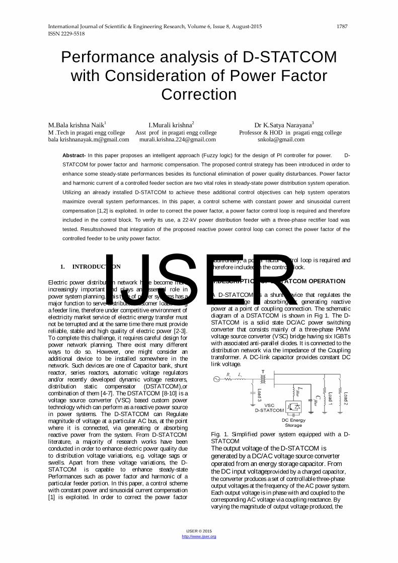
additionally, a power factor control loop is required and therefore included in the control block. I I .DESCRIPTION OF D-STATCOM OPERATION A D-STATCOM is a shunt device that regulates the system voltage by absorbing or generating reactive power at a point of coupling connection. The schematic diagram of a DSTATCOM is shown in Fig 1. The D-STATCOM is a solid state DC/AC power switching converter that consists mainly of a three-phase PWM voltage source converter (VSC) bridge having six IGBTs with associated anti-parallel diodes. It is connected to the distribution network via the impedance of the Coupling transformer. A DC-link capacitor provides constant DC link voltage.
Fig. 1. Simplified power system equipped with a D-STATCOM The output voltage of the D-STATCOM is generated by a DC/AC voltage source converter operated from an energy storage capacitor. From the DC input voltageprovided by a charged capacitor, the converter produces a set of controllable three-phase output voltages at the frequency of the AC power system. Each output voltage is in phase with and coupled to the corresponding AC voltage via coupling reactance. By varying the magnitude of output voltage produced, the
IJSER
International Journal of Scientific & Engineering Research, Volume 6, Issue 8, August-2015 1788 ISSN 2229-5518
IJSER © 2015 http://www.ijser.org
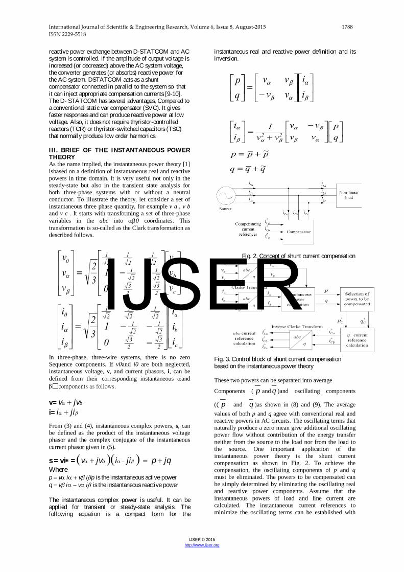
reactive power exchange between D-STATCOM and AC system is controlled. If the amplitude of output voltage is increased (or decreased) above the AC system voltage, the converter generates (or absorbs) reactive power for the AC system. DSTATCOM acts as a shunt compensator connected in parallel to the system so that it can inject appropriate compensation currents [9-10]. The D- STATCOM has several advantages, Compared to a conventional static var compensator (SVC). It gives faster responses and can produce reactive power at low voltage. Also, it does not require thyristor-controlled reactors (TCR) or thyristor-switched capacitors (TSC) that normally produce low order harmonics. I I I . BRIEF OF THE INSTANTANEOUS POWER THEORY As the name implied, the instantaneous power theory [1] isbased on a definition of instantaneous real and reactive powers in time domain. It is very useful not only in the steady-state but also in the transient state analysis for both three-phase systems with or without a neutral conductor. To illustrate the theory, let consider a set of instantaneous three phase quantity, for example v a , v b and v c . It starts with transforming a set of three-phase variables in the abc into αβ0 coordinates. This transformation is so-called as the Clark transformation as described follows.
In three-phase, three-wire systems, there is no zero Sequence components. If v0and i0 are both neglected, instantaneous voltage, v, and current phasors, i, can be defined from their corresponding instantaneous αand βcomponents as follows. v= vα + jvb
i= iα + jiβ From (3) and (4), instantaneous complex powers, s, can be defined as the product of the instantaneous voltage phasor and the complex conjugate of the instantaneous current phasor given in (5).
s = vi∗ = (vα + jvb )(iα − jiβ ) = p + jq Where p = vα iα + vβ iβp is the instantaneous active power q = vβ iα − vα iβ is the instantaneous reactive power The instantaneous complex power is useful. It can be applied for transient or steady-state analysis. The following equation is a compact form for the
instantaneous real and reactive power definition and its inversion.
Fig. 2. Concept of shunt current compensation
Fig. 3. Control block of shunt current compensation based on the instantaneous power theory These two powers can be separated into average
Components ( p and q )and oscillating components
(( p and q )as shown in (8) and (9). The average values of both p and q agree with conventional real and reactive powers in AC circuits. The oscillating terms that naturally produce a zero mean give additional oscillating power flow without contribution of the energy transfer neither from the source to the load nor from the load to the source. One important application of the instantaneous power theory is the shunt current compensation as shown in Fig. 2. To achieve the compensation, the oscillating components of p and q must be eliminated. The powers to be compensated can be simply determined by eliminating the oscillating real and reactive power components. Assume that the instantaneous powers of load and line current are calculated. The instantaneous current references to minimize the oscillating terms can be established with
IJSER
International Journal of Scientific & Engineering Research, Volume 6, Issue 8, August-2015 1789 ISSN 2229-5518
IJSER © 2015 http://www.ijser.org
some efficient concepts. Fig. 3 shows a general idea of shunt current compensation based on the instantaneous power theory described in this section. IV.PROPOSED CONTROL STRATEGY FOR D-
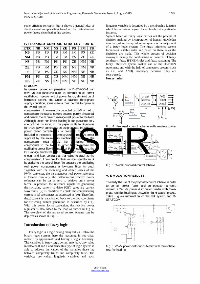
STACOM In general, power compensation by D-STACOM can have various functions such as elimination of power oscillation, improvement of power factor, elimination of harmonic current, etc. Under a balanced three-phase supply condition, some criteria must be met to optimize the overall system compensation. The research conducted by [3-6] aimed to compensate the source current become purely sinusoidal and deliver the minimum average real power to the load. Although under non-linear loading it can guarantee only one optimal criterion, in this paper multiple objectives for shunt power compensation are proposed. In addition, power factor correction of a protected load can be included in the control scheme by zeroing reactive power supplied by the source. As mentioned previously, the compensator must supply the oscillating power components to the load. In order to compensate the oscillating power flow by means of PWM converters, the DC voltage across the DC link capacitor must be large enough and kept constant at that value to stabilize the compensation. Therefore, DC link voltage regulator must be added to the control loop. To separate the oscillating real power components a low-pass filter is used. Together with the switching and ohmic losses of the PWM converter, the instantaneous real power reference is formed. Similarly, the instantaneous reactive power reference can be set as zero to achieve unity power factor. In practice, the reference signals for generating the switching pattern to drive IGBT gates are current waveforms, (7) is modified to equate the compensating current in αβcoordinates as expressed in (10). Therefore, theαβcurrent is transformed back to the abc coordinate for switching pattern generation as described by (11). With this power factor correction, the reactive power regulator is also added to the loop as shown in Fig. 4. The overview of the proposed control scheme can be depicted as shown in Fig. 5. Introduction to fuzzy logic
Fuzzy logic is a logic having many values. Unlike the binary logic system, here the reasoning is not crisp, rather it is approximate and having a vague boundary. The variables in fuzzy logic system may have any value in between 0 and 1 and hence this type of logic system is able to address the values of the variables those lay between completely truths and completely false. The variables are called linguistic variables and each
linguistic variable is described by a membership function which has a certain degree of membership at a particular instance. System based on fuzzy logic carries out the process of decision making by incorporation of human knowledge into the system. Fuzzy inference system is the major unit of a fuzzy logic system. The fuzzy inference system formulates suitable rules and based on these rules the decisions are made. This whole process of decision making is mainly the combination of concepts of fuzzy set theory, fuzzy IFTHEN rules and fuzzy reasoning. The fuzzy inference system makes use of the IF-THEN statements and with the help of connectors present (such as OR and AND), necessary decision rules are constructed. Fuzzy rules
Fig. 4. Proposed control scheme with reactive power regulation
Fig. 5. Overall proposed control scheme V. SIMULATION RESULTS To verify the use of the proposed control scheme in order to correct power factor and compensate harmonic current, a 22- kV power distribution feeder with three-phase rectifier loading as shown in Fig. 6 was employed. Table I gives information of the test system and D-STATCOM.
Fig. 6. 22-kV power distribution feeder with three-phase rectifier loading
E/EC NB NM NS ZE PS PM PB NB PB PB PB PM PM PS ZE NM PB PB PM PM PS ZE ZE NS PB PM PS PS ZE NM NB
ZE PB PM PS ZE NS NM NB PS PM PS ZE NS NM NB NB PM PS ZE NS NM NM NB NB PB ZE NS NM NM NB NB NB
IJSER
International Journal of Scientific & Engineering Research, Volume 6, Issue 8, August-2015 1790 ISSN 2229-5518
IJSER © 2015 http://www.ijser.org
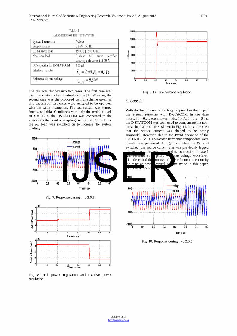
The test was divided into two cases. The first case was used the control scheme introduced by [1]. Whereas, the second case was the proposed control scheme given in this paper.Both test cases were assigned to be operated with the same instruction. The test system was started from zero initial Conditions with only the rectifier load. At t = 0.2 s, the DSTATCOM was connected to the system via the point of coupling connection. At t = 0.5 s, the RL load was switched on to increase the system loading.
Fig. 7. Response during t =0.2,0.5
Fig. 8. real power regulation and reactive power regulation
Fig. 9 DC link voltage regulation
B. Case 2: With the fuzzy control strategy proposed in this paper, the system response with D-STACOM in the time interval 0 – 0.2 s was shown in Fig. 10. At t = 0.2 – 0.5 s, the D-STATCOM was connected to compensate the non-linear load as responses shown in Fig. 11. It can be seen that the source current was shaped to be nearly sinusoidal. However, due to the PWM operation of the D-STATCOM, higher-order harmonic components were inevitably experienced. At t ≥ 0.5 s when the RL load switched, the source current that was previously lagged the voltage at the point of coupling connection in case 1 was resumed to in-phase with the voltage waveform. This described the success of power factor correction by the reactive power control scheme made in this paper. This can be seen in Fig. 12.
Fig. 10. Response during t =0.2,0.5
IJSER
International Journal of Scientific & Engineering Research, Volume 6, Issue 8, August-2015 1791 ISSN 2229-5518
IJSER © 2015 http://www.ijser.org
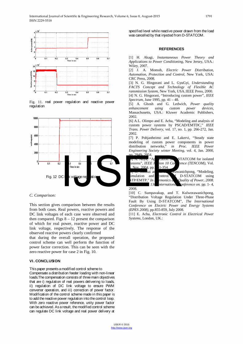
Fig. 11. real power regulation and reactive power regulation
Fig. 12 DC link voltage regulation C. Comparison: This section gives comparison between the results from both cases. Real powers, reactive powers and DC link voltages of each case were observed and then compared. Figs 8 – 12 present the comparison of which for real power, reactive power and DC link voltage, respectively. The response of the observed reactive powers clearly confirmed that during the overall operation, the proposed control scheme can well perform the function of power factor correction. This can be seen with the zero reactive power for case 2 in Fig. 10. VI . CONCLUSION
This paper presents a modified control scheme to Compensate a distribution feeder loading with non-linear loads.The compensation consists of three main objectives that are i) regulation of real powers delivering to loads, ii) regulation of DC link voltage to ensure PWM converter operation, and iii) correction of power factor. Modification of the control scheme made in this paper is to add the reactive power regulation into the control loop. With zero reactive power reference, unity power factor can be achieved. As a result, the modified control scheme can regulate DC link voltage and real power delivery at
specified level while reactive power drawn from the load was cancelled by that injected from D-STATCOM.
REFERENCES
[1] H. Akagi, Instantaneous Power Theory and Applications to Power Conditioning, New Jersey, USA.: Wiley, 2007. [2] J. A. Momoh, Electric Power Distribution, Automation, Protection and Control, New York, USA: CRC Press, 2008. [3] N. G. Hingorani and L. GyuGyi, Understanding FACTS Concept and Technology of Flexible AC ransmission System, New York, USA.:IEEE Press, 2000. [4] N. G. Hingorani, “Introducing custom power”, IEEE Spectrum, June 1995, pp. 41 – 48. [5] A. Ghosh and G. Ledwich, Power quality enhancement using custom power devices, Massachusetts, USA.: Kluwer Academic Publishers, 2002. [6] A.L. Olimpo and E. Acha, “Modeling and analysis of custom power systems by PSCAD/EMTDC,” IEEE Trans. Power Delivery, vol. 17, no. 1, pp. 266-272, Jan. 2002. [7] P. Pohjanheimo and E. Lakervi, “Steady state modeling of custom power components in power distribution networks,” in Proc. IEEE Power Engineering Society winter Meeting, vol. 4, Jan. 2000, pp. 2949- 2954. [8] A. Adya, “Application of D-STATCOM for isolated systems”, IEEE Region 10 Conference (TENCOM), Vol. 3, Nov. 2004, pp. 351-354. [9] K. Somsai and T. Kulworawanichpong, “Modeling, simulation and control of D-STATCOM using ATP/EMTP,” In Harmonics and Quality of Power, 2008. ICHQP 2008. 13th International Conference on. pp. 1- 4, 2008. [10] C. Sumpavakup, and T. Kulworawanichpong, “Distribution Voltage Regulation Under Three-Phase Fault By Using D-STATCOM”, The International Conference on Electric Power and Energy Systems (EPES 2008), pp.855-859, July 2008. [11] E. Acha, Electronic Control in Electrical Power Systems, London, UK.:
IJSER