PERFORMANCE A O A C YCLE AS TURBINE … · The combined cycle gas turbine integrates the Brayton...
15
Mechanical Engineering: An International Journal ( MEIJ), Vol. 1, No. 2, August 2014 11 PERFORMANCE ANALYSIS OF A COMBINED CYCLE GAS TURBINE UNDER VARYING OPERATING CONDITIONS Dillip Kumar Mohanty*, Vijay Venkatesh BITS Pilani K K Birla Goa Campus, Zuari Nagar, Goa - 403726 Abstract : The combined cycle gas turbine integrates the Brayton cycle as topping cycle and the steam turbine Rankine cycle as bottoming cycle in order to achieve higher thermal efficiency and proper utilization of energy by minimizing the energy loss to a minimum. In this work, the effect of various operating parameters such as maximum temperature and pressure of Rankine cycle, turbine inlet temperature and pressure ratio of Brayton cycle on the net output work and thermal efficiency of the combine cycle are investigated. The outcome of this work can be utilized in order to facilitate the design of a combined cycle with higher efficiency and output work. A MATLAB simulation has been carried out to study the effects and influences of the above mentioned parameters on the efficiency and work output. Key-words : Brayton Cycle; Rankine Cycle; Combined Cycle Gas Turbine; Efficiency; Pressure ratio. 1. INTRODUCTION: The combined cycle gas turbine (CCGT) technology has attracted much attention by the researchers in the last few decades by utilizing the Brayton cycle gas turbine and Rankine cycle steam turbine with air and water as working fluids to achieve efficient, reliable, and economic power generation. Currently overall thermal efficiencies up to 60% are confirmed by the foremost manufacturers from the sector as state of the art and special modifications have been proposed to improve the overall thermal efficiencies more than 60%. Higher efficiency level in CCGT up to 65% can be achieved by incorporating enhancements in the gas turbine technology such as higher compression ratio, turbine inlet temperature and ambient condition. The improvement in HRSG design, the use of advanced thermodynamic plant configurations such as two shaft gas turbine, combining intercooler cycle and regenerative cycle may be adopted to improve the thermal efficiency. The most commonly used means in industrial practice for generation of mechanical power is the utilization of gas and steam turbines. Different means have been employed by a lot of researchers to get better thermal efficiency of the turbines. Combining two or more thermodynamic cycles result in improved overall efficiency, reducing fuel costs. In stationary power plants, a widely
Transcript of PERFORMANCE A O A C YCLE AS TURBINE … · The combined cycle gas turbine integrates the Brayton...

Mechanical Engineering: An International Journal ( MEIJ), Vol. 1, No. 2, August 2014
11
PERFORMANCE ANALYSIS OF A COMBINED
CYCLE GAS TURBINE UNDER VARYING
OPERATING CONDITIONS
Dillip Kumar Mohanty*, Vijay Venkatesh
BITS Pilani K K Birla Goa Campus, Zuari Nagar, Goa - 403726
Abstract : The combined cycle gas turbine integrates the Brayton cycle as topping cycle and the steam turbine
Rankine cycle as bottoming cycle in order to achieve higher thermal efficiency and proper utilization of
energy by minimizing the energy loss to a minimum. In this work, the effect of various operating
parameters such as maximum temperature and pressure of Rankine cycle, turbine inlet temperature and
pressure ratio of Brayton cycle on the net output work and thermal efficiency of the combine cycle are
investigated. The outcome of this work can be utilized in order to facilitate the design of a combined cycle
with higher efficiency and output work. A MATLAB simulation has been carried out to study the effects and
influences of the above mentioned parameters on the efficiency and work output.
Key-words : Brayton Cycle; Rankine Cycle; Combined Cycle Gas Turbine; Efficiency; Pressure ratio.
1. INTRODUCTION: The combined cycle gas turbine (CCGT) technology has attracted much attention by the
researchers in the last few decades by utilizing the Brayton cycle gas turbine and Rankine cycle
steam turbine with air and water as working fluids to achieve efficient, reliable, and economic
power generation. Currently overall thermal efficiencies up to 60% are confirmed by the foremost
manufacturers from the sector as state of the art and special modifications have been proposed to
improve the overall thermal efficiencies more than 60%. Higher efficiency level in CCGT up to
65% can be achieved by incorporating enhancements in the gas turbine technology such as higher
compression ratio, turbine inlet temperature and ambient condition. The improvement in HRSG
design, the use of advanced thermodynamic plant configurations such as two shaft gas turbine,
combining intercooler cycle and regenerative cycle may be adopted to improve the thermal
efficiency.
The most commonly used means in industrial practice for generation of mechanical power is the
utilization of gas and steam turbines. Different means have been employed by a lot of researchers
to get better thermal efficiency of the turbines. Combining two or more thermodynamic cycles
result in improved overall efficiency, reducing fuel costs. In stationary power plants, a widely

Mechanical Engineering: An International Journal ( MEIJ), Vol. 1, No. 2, August 2014
12
used combination is a gas turbine operating by the Brayton cycle whose hot exhaust powers a
steam power plant operating by the Rankine cycle. This is called a Combined Cycle Gas Turbine
(CCGT) plant, and can achieve a thermal efficiency of around 60%, in contrast to a single cycle
steam power plant which is limited to efficiencies of around 35-42%. When combined, the gas
turbine (GT) Brayton cycle and the steam turbine (ST) power plant Rankine cycle complement
each other to form an efficient CCGT. The Brayton cycle has a high source temperature and
rejects heat at a temperature that is conveniently used as the energy source for the Rankine cycle
plant [1].
The gas turbine is a quite complex equipment and its performance and reliability are governed by
many a number of parameters. The major variables that affect the gas turbines include type of
application, plant location and site configuration, plant size and efficiency, type of fuel,
enclosures and plant operation mode like base or peaking [2]. The performance of the gas turbine
relies mostly on the efficiency achieved at the compressor of the turbine. The performance and
reliabilty improvement of the gas turbine is dependent on the maximum temperature tolerance of
the first stage blades and is also reliant on inter stage cooling at the compression stage [3].
Many researchers have focussed on improvement in the modeling of CCGT power plant system
utilizing the Brayton Cycle gas turbine and Rankine Cycle steam turbine with air and water as
working fluids. Many of these methods such as use of air cooler [4], regenerative steam injection
[5], effusive blade cooling techniques [6], use of desiccant-based evaporative cooling [7] or
absorption chillers [8] are commonplace. Kaushika et al. [9] studied the optimum performance of
a CCGT by modeling and simulation. The best combination of process parameters of steam
leaving the steam generator was determined at part load operation for optimum performance of
the CCGT. Khaliq and Kaushik [10] developed a simulator of the combined-cycle co-generation
power plant by a mathematical model for power plant modeling. The simulator was consisting of
two parts out of which the first one was a simulation of fluid flow in the power plant and the
second part was a simulation of the control system of the plant.
The thermal impact of operating conditions on the performance of a combined cycle gas turbine
was investigated by Ibrahim and Rahman [11]. They have studied effects of varying the operating
conditions such as ambient temperature, compression ratio, turbine inlet temperature, isentropic
compressor and turbine efficiencies, and mass flow rate of steam on the overall efficiency and
total output power of the CCGT. Rai et. al. [12] presented a model of gas turbine for optimizing
the power of CCGT by varying different operating parameters. According to their studies the
efficiency of a gas turbine which ranges from 28% to 33% can be raised to about 60% by
recovering some of the low grade thermal energy from the exhaust gas for steam turbine process.
This work presents a matlab simulation based study of variation of the work output and thermal
efficiency on operating parameters such as maximum temperature, maximum pressure, pressure
ratio and turbine inlet temperature. The CCGT consists of a topping Brayton cycle and the
bottoming cycle is a steam tubine Rankine cycle.
2. THERMODYNAMIC MODELLING OF THE CCGT CYCLE
A combined cycle gas turbine power plants having Bray-ton cycle based topping cycle and
Rankine cycle based bot-toming cycle has been considered for the present study and analysis of

Mechanical Engineering: An International Journal ( MEIJ), Vol. 1, No. 2, August 2014
13
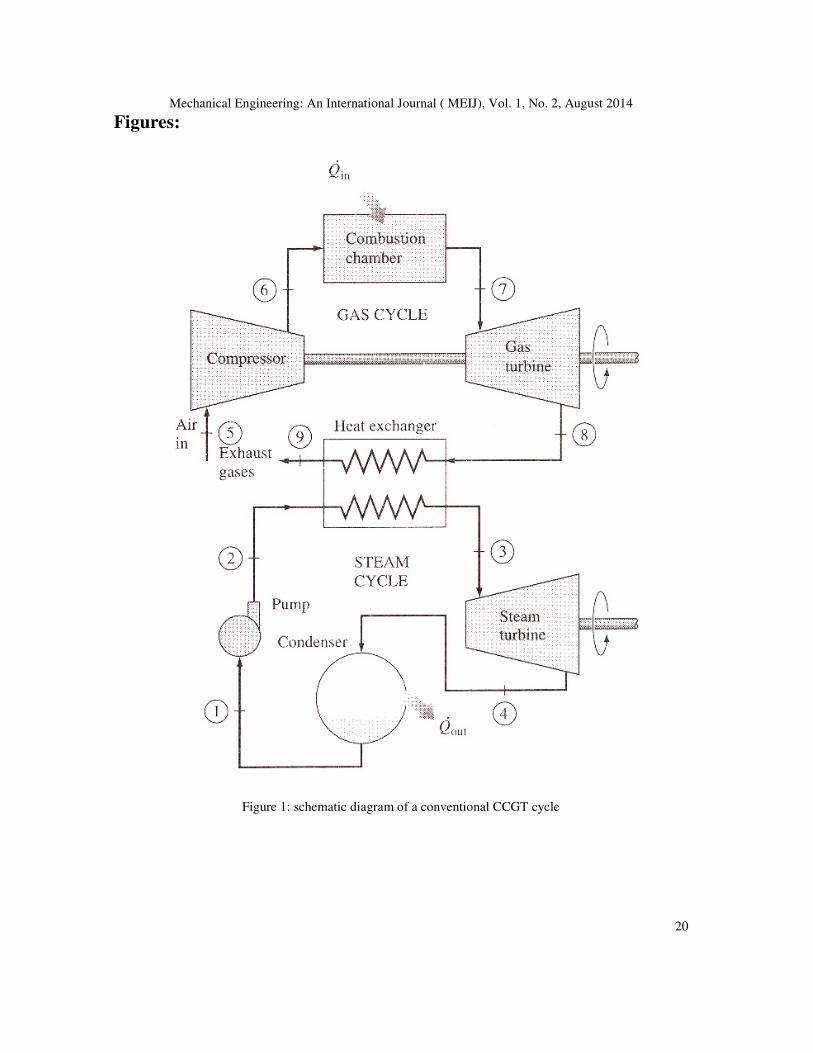
variation in work out and thermal efficiency for different operating conditions. Figure 1 [13]
shows the schematic of a conventional CCGT with topping Brayton cycle and bottoming Rankine
cycle. Generally the Gas turbine power plants consist of four major components namely the
compressor, combustion chamber, turbine and generator. According to the basic principle of the
CCGT, the air is compressed by the air compressor and transferred to the combustion chamber
where it combines with liquid or gaseous fuel for producing high-temperature flue gas through
the process of combustion. Hot gases leaving the combustion chamber expands in the turbine
thereby producing output work and finally discharges to the atmosphere. The waste exhaust gas
temperature from gas turbine decreases as it flows into the heat recovery steam generator
(HRSG), which consists of superheater, evaporator and economizer. Then the HRSG supplies a
steam for the steam turbine in producing electricity. The temperature-entropy plot of a commonly
used CCGT cycle is presented in Figure 2 [13]. The systematic modeling of a CCGT is presented
in following steps.
The concept of compressor polytropic efficiency can be developed considering the definition of
the isentropic or overall compressor efficiency with reference to the pressure ratio.
The ideal and actual processes on the temperature-entropy diagram for an actual and ideal
Brayton cycle are shown in Figure 3 [2]. Let the compressor and turbine efficiency is ηc and ηT
respectively.
2.1 Air Compressor Model:
The compressor efficiency can be determined taking into account the deviation of the actual cycle
from the ideal cycle. The compression ratio across the compressor is given as
2
1
p
Pr
P= (1)
where rp is the compression ratio, P1 is the initial pressure before compression and P2 is the
pressure after compression.
The isentropic efficiency of compressor (ηc) can be given as
2 1
2 1
c
T T
T Tη
′
−=
− (2)
where T1 is the compressor inlet temperature, T2 is the temperature at the end of isentropic
compression and T2’ is the temperature at the end of actual compression.
The same principle can be applied to the gas turbine expansion process to determine the turbine
efficiency.
3 4
3 4
T
T T
T Tη ′−
=−
(3)
where,

Mechanical Engineering: An International Journal ( MEIJ), Vol. 1, No. 2, August 2014
14
ηT = Isentropic efficiency of turbine
T3 = Turbine inlet temperature
T4 = Turbine exit temperature in isentropic expansion process.
T4’ = Turbine exit temperature during actual expansion process.
The actual temperature at the outlet of compressor can be calculated taking into account the
compressor efficiency (ηc) and the specific heat ratio for air (γa).
1
2 1
11
a
a
p
c
rT T
γ
γ
η
−
′
−
= +
(4)
These relationships can be further expressed as [1]
1
1
a
a
p
pa
c
rR
γ
γ
η
−
−= (5)
1
11
g
g
pg
p
R
r
γ
γ
−= − (6)
The compressor work neglecting the blade cooling (Wc) can be calculated as
1
1
1
1
a
a
pa p
pa pa
c
m c m
C T rC T R
W
γ
γ
η η η
− × −
× × = =×
(7)
where ηm is the mechanical efficiency of the compressor and Cpa is the specific heat of air. The
specific heat of air can be determined by considering the empirical relations depending on the
working range of temperature.[14]
2.2 Combustion Chamber Model:
The combustion chamber is a component of gas turbine where combustion takes place. The
combustion chamber is fed with high pressure air which is being heated at constant pressure
before being passed through the nozzle guide vanes to the turbine. The basic principle of
operation of a combustion chamber is based on the energy balance principle. Applying the
principle of energy balance [15],
( )2a pa f f pf f a f pgm C T m LHV m C T m m C TIT′ + × + = + × (8)

Mechanical Engineering: An International Journal ( MEIJ), Vol. 1, No. 2, August 2014
15
where mf is the mass flow rate of fuel (kg/s), ma is the mass flow rate of air(kg/s), LHV is low
heating value, TIT is the turbine inlet temperature, Cpf is the specific heat of fuel, and Tf is the
temperature of the fuel. The specific heat of the flue gas can be determined from the empirical
relations available in literature. However in this work, the relationship developed by Naradasu et.
al. is taken into consideration [16].
3 6 2 9 31.8083 2.3127 10 4.045 10 1.7363 10pgC T T T− − −= − × + × − × (9)
The air fuel ratio can be expressed as
( )1 1
pg pa pgf
a pf f pg
C TIT C T Rm
m LHV C T C TIT
× − +=
+ × − × (10)
2.3 Gas Turbine Model:
A gas turbine, also known as combustion turbine has an upstream rotating compressor coupled to
a downstream turbine, and a combustion chamber in-between. Fresh atmospheric air flows
through a compressor that brings it to higher pressure. Energy is then added by spraying fuel into
the air and igniting it so the combustion generates a high-temperature flow. This high-temperature
high-pressure gas enters a turbine, where it expands down to the exhaust pressure, producing a
shaft work output in the process.
The exhaust gas temperature of the gas turbine can be expressed as
4 3 1
11 1
g
g
T
p
T T
r
γ
γ
η′ ′ −
= − × −
(11)
The total output work of the turbine (WT) is expressed as
/T pg T pg m
W C TIT Rη η= × × × (12)
Hence the net work output of the gas turbine is
net T C
W W W= − (13)
The total heat supplied is given as
( )1 1 1pg pa
Q C TIT T R = − + (14)
Hence the thermal efficiency of the gas turbine can be determined as
1
netth
W
Qη = (15)\

Mechanical Engineering: An International Journal ( MEIJ), Vol. 1, No. 2, August 2014
16
2.4 Steam Turbine Model
The behavior of the subsystems of a steam turbine cycle can be captured in terms of the mass and
energy conservation equations, semi-empirical relations and thermodynamic state conservation.
The system dynamics is represented by a number of lumped models for each subsections of
turbine. There are many dynamic models for individual components, which are simple empirical
relations between system variables with a limited number of parameters and can be validated for
the steam turbine by using real system responses. In this work, a single pressure heat recovery
steam generator (HRSG) is considered here as a common type for the combined cycle gas turbine
power plant. Applying energy balance, the heat available with exhaust gases (Qa) from the gas
turbine can be given as
( )1 4 1a g pg g g fQ m C T T h= × × − × (16)
where Tg4 is the exhaust temperature from HRSG and h1f is the heat loss factor. Generally the heat
loss factor varies within a range from 0.98 to 0.99 [17]. Similarly the energy balance can be
applied to determine the temperature of the exhaust hot gases exit from the HRSG.
( ) ( )1 1 4s sh w g pg g gm h h m C T T− = − (17)
The steam obtained from HRSG expands to the condenser pressure in the steam turbine. The
energy balance of steam turbine as represented in Figure 1 gives
( )3 4s sW m h h= − (18)
The heat rejected in the condenser is given as
( )4 1c wQ m h h= − (19)
Similarly, the pump work can be determined as
( )1p w f sh cW m v P P= − (20)
The net output work of the steam turbine plant is
snet s p
W W W= − (21)
Thus the overall thermal efficiency (ηoverall) of the combined cycle is
net snetoverall
a
W W
Qη
+= (22)
3. RESULTS AND DISCUSSION
The effect of various operating conditions such as maximum temperature, turbine inlet
temperature, pressure ratio and maximum pressure on the output work and thermal efficiency of
the cycle have been considered in this work. The MATLAB script is utilized to investigate the
required objectives.
Figure 3 represents the variation of output work with maximum pressure for different cases of
maximum steam turbine cycle temperature. In this case the pressure ratio remains fixed at 7 while
the turbine inlet temperature is fixed at 1500K. Three different conditions of steam turbine cycle
Mechanical Engineering: An International Journal ( MEIJ), Vol. 1, No. 2, August 2014
17
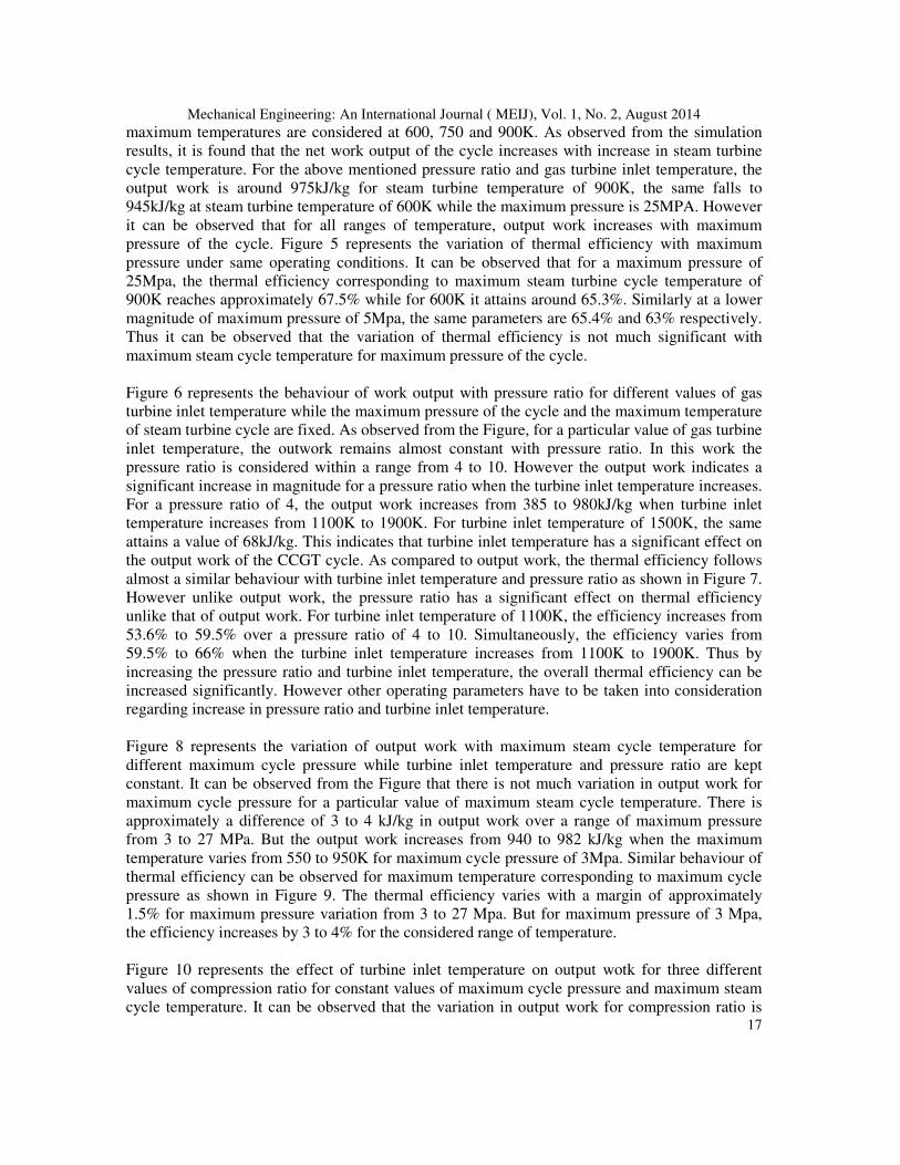
maximum temperatures are considered at 600, 750 and 900K. As observed from the simulation
results, it is found that the net work output of the cycle increases with increase in steam turbine
cycle temperature. For the above mentioned pressure ratio and gas turbine inlet temperature, the
output work is around 975kJ/kg for steam turbine temperature of 900K, the same falls to
945kJ/kg at steam turbine temperature of 600K while the maximum pressure is 25MPA. However
it can be observed that for all ranges of temperature, output work increases with maximum
pressure of the cycle. Figure 5 represents the variation of thermal efficiency with maximum
pressure under same operating conditions. It can be observed that for a maximum pressure of
25Mpa, the thermal efficiency corresponding to maximum steam turbine cycle temperature of
900K reaches approximately 67.5% while for 600K it attains around 65.3%. Similarly at a lower
magnitude of maximum pressure of 5Mpa, the same parameters are 65.4% and 63% respectively.
Thus it can be observed that the variation of thermal efficiency is not much significant with
maximum steam cycle temperature for maximum pressure of the cycle.
Figure 6 represents the behaviour of work output with pressure ratio for different values of gas
turbine inlet temperature while the maximum pressure of the cycle and the maximum temperature
of steam turbine cycle are fixed. As observed from the Figure, for a particular value of gas turbine
inlet temperature, the outwork remains almost constant with pressure ratio. In this work the
pressure ratio is considered within a range from 4 to 10. However the output work indicates a
significant increase in magnitude for a pressure ratio when the turbine inlet temperature increases.
For a pressure ratio of 4, the output work increases from 385 to 980kJ/kg when turbine inlet
temperature increases from 1100K to 1900K. For turbine inlet temperature of 1500K, the same
attains a value of 68kJ/kg. This indicates that turbine inlet temperature has a significant effect on
the output work of the CCGT cycle. As compared to output work, the thermal efficiency follows
almost a similar behaviour with turbine inlet temperature and pressure ratio as shown in Figure 7.
However unlike output work, the pressure ratio has a significant effect on thermal efficiency
unlike that of output work. For turbine inlet temperature of 1100K, the efficiency increases from
53.6% to 59.5% over a pressure ratio of 4 to 10. Simultaneously, the efficiency varies from
59.5% to 66% when the turbine inlet temperature increases from 1100K to 1900K. Thus by
increasing the pressure ratio and turbine inlet temperature, the overall thermal efficiency can be
increased significantly. However other operating parameters have to be taken into consideration
regarding increase in pressure ratio and turbine inlet temperature.
Figure 8 represents the variation of output work with maximum steam cycle temperature for
different maximum cycle pressure while turbine inlet temperature and pressure ratio are kept
constant. It can be observed from the Figure that there is not much variation in output work for
maximum cycle pressure for a particular value of maximum steam cycle temperature. There is
approximately a difference of 3 to 4 kJ/kg in output work over a range of maximum pressure
from 3 to 27 MPa. But the output work increases from 940 to 982 kJ/kg when the maximum
temperature varies from 550 to 950K for maximum cycle pressure of 3Mpa. Similar behaviour of
thermal efficiency can be observed for maximum temperature corresponding to maximum cycle
pressure as shown in Figure 9. The thermal efficiency varies with a margin of approximately
1.5% for maximum pressure variation from 3 to 27 Mpa. But for maximum pressure of 3 Mpa,
the efficiency increases by 3 to 4% for the considered range of temperature.
Figure 10 represents the effect of turbine inlet temperature on output wotk for three different
values of compression ratio for constant values of maximum cycle pressure and maximum steam
cycle temperature. It can be observed that the variation in output work for compression ratio is

Mechanical Engineering: An International Journal ( MEIJ), Vol. 1, No. 2, August 2014
18
not much significant. There is approximately a difference of 20 to 25kJ of output work is
observed for difference in pressure ratio from 4 to 10. For pressure ratio of 4, the output increases
from 310 to 920 kJ/kg when the turbine inlet temperature increases from 1100K to 1900K.
Similar trend is observed for other values of pressure ratios. Thus the turbine inlet temperature
significantly affects the output work. Figure 11 represents the variation of thermal efficiency with
turbine inlet temperature for constant values of maximum cycle pressure and maximum steam
cycle temperature. The efficiency has been considered for pressure ratio values 4, 7 and 10.
Unlike output work, distinctive effect of pressure ratio on efficiency is observed. For turbine inlet
temperature of 1100K, the efficiency increases from 59.5% 64.6% when pressure ratio is varied
from 4 to 10. Similarly for same range of pressure ratio, efficiency increases from 65.8 to 69.8%
when turbine inlet temperature is 1900K. In a similar manner, significant effect of turbine inlet
temperature on efficiency is observed for a particular pressure ratio. For pressure ratio 4, the
efficiency increases from 59.5% to 65.8% over a range of turbine inlet temperature from 1100K
to 1900K. Almost a similar trend is obtained for pressure ratio 7 and 10. However for pressure
ratio 10, an abrupt trend of efficiency is observed within turbine inlet temperature from 1600K to
1800K. This may be due to some computational error. Besides it can be clearly observed that the
overall thermal efficiency of a CCGT cycle can be improved significantly by increasing the
turbine inlet temperature keeping in view the mechanical constraints.
5. CONCLUSION: A model of CCGT was developed and variation of output work and thermal efficiency by varying
various operating parameters were studied. The simulated modeling results show that the
maximum cycle pressure, maximum temperature, pressure ratio and turbine inlet temperature
have significant effects on the performance of the CCGT.
For constant pressure ratio and turbine inlet temperature, outwork and thermal efficiency are
strongly influenced by maximum cycle pressure and maximum temperature of steam turbine
cycle.
For constant maximum cycle pressure and maximum temperature of steam turbine, the output
work is not much affected by pressure ratio, but it is strongly affected by turbine inlet
temperature. However under similar operating conditions, efficiency is significantly affected by
both pressure ratio and turbine inlet temperature.
For constant turbine inlet temperature and pressure ratio, both output work and efficiency
increases with maximum cycle pressure and maximum temperature of steam turbine cycle.
However a significant increase occurs in output work with maximum steam turbine cycle
temperature.
For maximum cycle pressure and maximum temperature of steam turbine temperature being
maintained constant, both the output work and thermal efficiency are not much affected by
pressure ratio, but significantly affected by turbine inlet temperature.
Hence keeping in view the mechanical constraints the above mentioned parameters can be
monitored in order to achieve higher thermal efficiency and output work of a combine cycle gas
turbine.
Mechanical Engineering: An International Journal ( MEIJ), Vol. 1, No. 2, August 2014
19
ACKNOWLEDGEMENTS: The authors are thankful to BITS Pilani K K Birla Goa Campus, Goa for their support in carrying
out this research work.
REFERENCES:
[1] Thamir K. Ibrahim, M.M. Rahman,(2012) “Effect of Compression Ratio on Performance of
Combined Cycle Gas Turbine”, International Journal of Energy Engineering , Vol. 2, No. 1, pp 9-14.
[2] Ashley De Sa, Sarim Al Zubaidy, (2011) “Gas turbine performance at varying ambient temperature”,
Applied Thermal Engineering, Vol. 31, pp 2735 – 2739.
[3] Carniere H., Willocx A., Dick E., Paepe M De., (2006) “Raising cycle efficiency by inter cooling in
air cooled gas turbine”, Applied Thermal Engineering, Vol. 26, No. 16, pp 1780 – 1787.
[4] AlHazmy M.M., Najjar Y.S.H.,(2004) “Augmentation of gas turbine performance using air coolers”,
Applied Thermal Engineering, Vol 24, No. 2-3, pp 415-429.
[5] Nishada, K., Takagi T., Kinoshita S.,(2005) “Regenerative steam injection gas turbine system”,
Applied Energy, Vol 81, pp 231-246.
[6] Rahman A., Al-Ibrahim, Abdulhadi V., (2010) “A review of inlet air cooling technologies for
enhancing its performance of combustion turbines in Saudi Arabia”, Applied Thermal Engineering,
Vol 30, No. 14-15, pp 1879-1888.
[7] Xiaojun S., Brian A., Defu C., Jiamin G., (2010) “Performance enhancement of conventional
combined cycle power plant by inlet air cooling, inter cooling and LNG cold energy utilization”,
Applied Thermal Engineering, Vol 30, No. 14-15, pp 2003-2010.
[8] Ameri M., Hejazi S.H, (2004) “The study of capacity enhancement of the chabahar gas turbine
installation using an absorption chiller”, Applied Thermal Engineering, Vol. 24, No. 1, pp 59-68.
[9] Kaushika S.C., Reddya V.S., Tyagi S.K.,(2011) “Energy and exergy analyses of thermal power
plants: A review” Renewable Sustainable Energy Review, Vol. 15, pp. 1857–1872.
[10] Khaliq A., Kaushik S.C.,(2004) “Thermodynamic performance evaluation of combustion gas turbine
cogeneration system with reheat”. Applied Thermal Engineering, Vol. 24, pp. 1785–1795.
[11] Thamir K. Ibrahim, Rahman M.M., “Thermal Impact of Operating Conditions on the Performance of
a Combined Cycle Gas Turbine”, Journal of Applied Research and Technology, pp 567 – 577.
[12] Rai J.N., Hasan N., Arora B.B., Garai R., Kapoor R and Ibrahim, (2013) “Performance Analysis of
CCGT Power Plant using MATLAB/Simulink Based Simulation”, International Journal of
Advancements in Research & Technology, Vol. 2, No. 5, .
[13] Palla M., (2007), “Analysis of the General Case of a Combined Gas-Steam Power Cycle”, Design
Project Report, Clarkson University.
[14] Sonntag R.E., Claus B. & Van Wylen G., “Fundamentals of Thermodynamics”, John Wiley & Sons,
2009, 7th ed.
[15] Firdaus B., Takanobu Y., Kimio N., Soe N.,(2011) “Effect of ambient temperature on the
performance of micro gas turbine with cogeneration system in cold region” Applied Thermal
Engineering, Vol. 31, pp. 1058– 1067.
[16] Naradasu R.K., Konijeti R.K., Alluru, V.R. (2007) “Thermodynamic analysis of heat recovery steam
generator in combined cycle power plant”, Thermal Science., Vol. 11, No. 4, pp. 143–156.
[17] Ganapathy V.,(1991) Waste Heat Boiler Deskbook. Indian Trail: Fairmont Press, Inc.
Mechanical Engineering: An International Journal ( MEIJ), Vol. 1, No. 2, August 2014
20
Figures:
Figure 1: schematic diagram of a conventional CCGT cycle

Mechanical Engineering: An International Journal ( MEIJ), Vol. 1, No. 2, August 2014
21
Figure 2 : Temperature-entropy plot of a CCGT cycle
Figure 3 : Temperature-entropy diagram for an actual and ideal Brayton cycle

Mechanical Engineering: An International Journal ( MEIJ), Vol. 1, No. 2, August 2014
22
Figure 4 : Variation of Work Output with Maximum pressure
Figure 5 : Variation of Thermal Efficiency with Maximum pressure

Mechanical Engineering: An International Journal ( MEIJ), Vol. 1, No. 2, August 2014
23
Figure 6 : Variation of Work Output with pressure ratio
Figure 7 : Variation of Thermal Efficiency with pressure ratio

Mechanical Engineering: An International Journal ( MEIJ), Vol. 1, No. 2, August 2014
24
Figure 8 : Variation of Work Output with Maximum temperature
Figure 9 : Variation of Thermal Efficiency with Maximum temperature

Mechanical Engineering: An International Journal ( MEIJ), Vol. 1, No. 2, August 2014
25
Figure 10 : Variation of Work Output with Turbine inlet temperature
Figure 11 : Variation of Thermal Efficiency with turbine inlet temperature