Percolation Testing and Reporting...
43
Percolation Testing and Reporting Standards for Onsite Wastewater Treatment Systems
Transcript of Percolation Testing and Reporting...

Percolation Testing and Reporting Standards
for Onsite Wastewater Treatment
Systems

Percolation Test Standards and Report Guide 2
Foreword
A soil percolation report uses water absorption rates for specific parcels of land to determine the appropriate onsite wastewater treatment systems (OWTS) that can be used for proposed development. The soil’s percolation condition at a specific parcel of land is determined by testing at the site. This information along with topographical, geologic, and hydrologic conditions are determined and described in the report. The OWTS is then designed in accordance with the report and San Bernardino County standards. A properly installed, operated and maintained OWTS is essential to prevent public health nuisances including odors, groundwater or surface water contamination, and safety hazards associated with premature system failure. Completed soil percolation reports and required fees must be submitted to Environmental Health Services (EHS) prior to the approval of the use of any OWTS and the application of the design rate. Note: This document was previously titled “Onsite Wastewater Disposal System Soil Percolation (PERC) Test Report Standards: Suitability of Lots and Soils for Use of Leach lines or Seepage Pits”. The title has been updated to reflect the primary purpose of the information presented.
Revised September 2019

Percolation Test Standards and Report Guide 3
Table of Contents
Definitions_______________________________________________________________________________ 5
Chapter One: PERC Submission Criteria and Requirements ________________________________________ 9
1.1 Circumstances Requiring Submission of a PERC report _______________________________________________ 9
1.2 Preparer Requirements ________________________________________________________________________ 9
Chapter Two: Required PERC Format and Content ______________________________________________ 10
2.1 Description of Site and Proposal ________________________________________________________________ 10
2.2 Proposed Development/Project/Land Use _______________________________________________________ 10
2.3 Description of Site and Surroundings ____________________________________________________________ 10
2.4 Equipment _________________________________________________________________________________ 11
Chapter Three: Methodology and Procedures _________________________________________________ 12
3.1 Location of Borings and Trenchings _____________________________________________________________ 12
3.2 Minimum Number of Exploratory Borings ________________________________________________________ 13
Chapter Four: Leach Lines Guidance _________________________________________________________ 14
4.1 Minimum Number of Tests for Leach lines _______________________________________________________ 14
4.2 Standard Percolation Test Procedure for Leach Lines ________________________________________________ 14
4.3 Continuous Pre-Soak Percolation Test Procedure for Leach Lines ______________________________________ 15
4.4 Results for Leach Lines _______________________________________________________________________ 17
4.5 Figure: Application Rates as Determined from Stabilized Percolation Rate for Leach Lines _________________ 18
4.6 Discussion of Results _________________________________________________________________________ 19
4.7 Design ____________________________________________________________________________________ 19
4.8 Convert Percolation Times to Leach Lines Design Rates _____________________________________________ 19
Chapter Five: Seepage Pits Guidance ________________________________________________________ 20
5.1 Minimum Number of Tests for Seepage Pit _______________________________________________________ 20
5.2 Standard Testing for Seepage Pit: Falling Head Percolation Test Procedure _____________________________ 20
5.3 Test Results for Seepage Pits __________________________________________________________________ 22
5.4 Discussion of Results _________________________________________________________________________ 22
5.5 Design ____________________________________________________________________________________ 23
5.6 Convert Q to Seepage Pit Design Rates __________________________________________________________ 23
Chapter Six: Special Criteria ________________________________________________________________ 24
6.1 Guidelines for Determining the Number of Bedrooms ______________________________________________ 24

Percolation Test Standards and Report Guide 4
6.2 Confluent Systems ___________________________________________________________________________ 24
6.3 Credit for Alternating Fields ___________________________________________________________________ 24
6.4 Special Soil Conditions _______________________________________________________________________ 25
6.5 Special Discharge Conditions __________________________________________________________________ 25
6.6 Alternative Treatment Systems ________________________________________________________________ 26
6.7 Alternative Sewage Disposal Options____________________________________________________________ 26
Chapter Seven: Plot Plan California Plumbing Code _____________________________________________ 28
Chapter Eight: General Recommendations ____________________________________________________ 29
APPENDIX ______________________________________________________________________________ 30
Appendix Figure A: Textural Triangle _______________________________________________________________ 31
Appendix Figure B: Unified Soil Classification ________________________________________________________ 32
Appendix Figure C: Design Soil Application Rates _____________________________________________________ 34
Appendix D: Liquid Waste Disposal Systems _________________________________________________________ 35
Appendix E: Daylight Requirements ________________________________________________________________ 38
Appendix F: Special Considerations for Absorption Field Placement in Sloping Ground _______________________ 38
Appendix G: Gravel Packing Corrections ____________________________________________________________ 39
Appendix H: Perennial Streams of San Bernardino County _____________________________________________ 399
Appendix I: Suggested References _________________________________________________________________ 41

Percolation Test Standards and Report Guide 5
Definitions
Alternative Onsite Sewage Disposal System
Any OWTS that does not meet the criteria of a conventional OWTS, but is allowed under conditions specified by EHS. These include supplemental treatment systems (see separate definition) and alternative dispersal system, such as pressured dose distribution systems.
Basin Plan (or Water Quality Control Plan)
A plan which identifies surface and ground water bodies within each region’s boundaries, and establishes for each, it’s respective beneficial uses, and water quality objectives. Basin plans are adopted by the RWQCB and SWRCB, and are approved by the Office of Administrative Law.
Bedrock
The rock, usually solid, which underlies soil or other unconsolidated, surficial material. Cesspool
An excavation in the ground receiving domestic wastewater, designed to retain the organic matter and solids, while allowing the liquids to seep into the soil. Cesspools differ from seepage pits because cesspools do not have a septic tank to pretreat the sewage prior to discharge into the soil.
Clay
Term used to describe a soil particle, or type of soil texture. As a soil:
Particle – clay consists of individual rock or mineral particles having diameters of <0.002 millimeters (mm).
Texture – clay is a soil material that is comprised of 40%, or more, clay particles, not more than 45% sand, and not more than 40% silt particles using the United States Department of Agriculture (USDA) soil classification system.
Cobbles
Rock fragments measuring 76 mm or larger, using the USDA soil classification systems. Dispersal System
A type of system for final wastewater treatment and subsurface discharge, which may include a leach field, seepage pit, mound, subsurface drip field, or evapotranspiration and infiltration bed.
Domestic Wastewater
Wastewater with a measured strength less than high strength wastewater, which is discharged from plumbing fixtures, appliances and other household devices.
Effluent
Sewage, water, or other liquid (partially or completely treated, or in its natural state), flowing out of a septic tank, aerobic treatment unit, dispersal system, or other OWTS component.
Grease Interceptor
A passive interceptor with a rate of flow exceeding 50 gallons-per-minute located outside a building, and used for separating and collecting grease from wastewater.
Groundwater
Water below the land surface that is at, or above, atmospheric pressure.

Percolation Test Standards and Report Guide 6
High Strength Wastewater
Wastewater, prior to septic tank or other form of OWTS treatment component, having:
A 30-day average concentration of Biochemical Oxygen Demand (BOD) greater than 300 milligrams per liter (mg/L),
Total Suspended Solids (TSS) greater than 330 mg/L, or
A Fats, Oil, and Grease (FOG) concentration greater than 100mg/L.
Impaired Water Bodies/303(d) List
Surface water bodies, or segments thereof, identified on the Section 303(d) list pursuant to the Federal Clean Water Act, approved by the SWRCB, and United States Environmental Protection Agency (EPA).
Local Agency
Any subdivision of state government responsible for permitting, installation, and regulation of OWTS within its jurisdictional boundaries; typically a county, city, or special district.
Local Agency Management Program (LAMP)
A program for the siting, design, operation and maintenance of OWTS, developed by a local agency, and approved by the RWQCB as an alternate method to achieve the same policy purpose as that of OWTS policy. Herein referred to as the Program.
Mottling
A soil condition that:
Results from oxidizing or reducing minerals due to soil moisture changes from saturated to unsaturated over time,
Is characterized by spots or blotches of different colors or, shades of color (grays and reds), interspersed within the dominant color as described by the USDA soil classification system, and
May indicate historic seasonal high ground water levels.
Mound System
An above grade dispersal system, having subsurface discharge, used to enhance soil treatment, dispersal, and absorption of effluent discharged from an OWTS treatment unit (e.g., septic tank).
National Sanitation Foundation (NSF) International
A not for profit, non-governmental organization which develops health and safety standards, and performs product certification.
Onsite Wastewater Treatment Systems (OWTS)
Wastewater treatment systems that use subsurface disposal, including: individual; community collection and disposal; and alternative collection and disposal systems.
Note: OWTS do not include “graywater” systems pursuant to Chapter 15 of the California Plumbing Code.
Percolation Test
A method of testing water absorption of the soil by using clean water to determine the dispersal system design.
Permit
A document issued by a local agency that allows the installation, use, and/or monitoring of an OWTS.

Percolation Test Standards and Report Guide 7
Qualified Professional
An individual licensed, or certified by a State of California agency, to design OWTS and practice as a professional for other associated reports, as allowed under their license or registration. Qualified Professionals include the following:
Registered Civil Engineers
Certified Engineering Geologists
Registered Environmental Health Specialists (REHSs)
Registered Geologists
Geotechnical Engineers.
Replacement OWTS
An OWTS that, after the effective date of this LAMP, has its treatment capacity expanded or its dispersal system replaced or added onto.
Regional Water Quality Control Board (RWQCB)
Regional Water Board is any of the Regional Water Quality Control Boards designated by California Water Code Section 13200. Any reference to an action of the Regional Water Board in this Policy also refers to an action of its Executive Officer. Depending on the site specific location of the OWTS, Regional Water Board reference in this document may refer to the Colorado River Basin Water Board, the Lahontan Water Board, or the Santa Ana Water Board.
Sand
A soil particle or type of soil texture. As a:
Soil particle – Sand consists of individual rock, or mineral particles, having diameters ranging from 0.05 to 2.0 mm.
Soil texture – Sand is soil that is comprised of 85% or more sand particles, with the percentage of silt plus 1.5 times the percentage of clay particles comprising less than 15%.
Seepage Pit
A drilled or dug excavation three to six feet in diameter. It is also gravel filled but has a hollow core with a minimum depth below the inlet of feet and receives effluent discharge for dispersal from a septic tank or other OWTS treatment unit.
Septic Tank
A watertight, covered, receptacle designed for primary treatment of wastewater and constructed to:
Receive wastewater discharged from a building,
Allow solids to settle and fats, oils, and grease to float,
Digest organic matter using anaerobic bacterial action,
Store digested solids, and
Clarify wastewater for further treatment with final subsurface discharge.
Service Provider
A person who is state licensed with knowledge and competency in OWTS design, construction operation, monitoring and maintaining an OWTS in accordance with this LAMP. For supplemental treatment, the individual must also be certified and/or trained extensively by the manufacturer of an OWTS with supplemental treatment to install, maintain, service, monitor and repair the specific model/type of OWTS.

Percolation Test Standards and Report Guide 8
Silt
A soil particle or type of soil texture. As a:
Soil particle – Silt consists of individual rock, or mineral particles, having diameters ranging from 0.05 to 0.002mm.
Soil texture – Silt is soil that is comprised of approximately 80% or more silt particles, and not more than 12% clay particles using the USDA soil classification system.
Site
The location of the OWTS and/or a reserve dispersal area, capable of disposing 100% of the design flow from all the sources the OWTS is intended to serve.
Site Evaluation
An assessment of the characteristics of the site, sufficient to determine its suitability for an OWTS that meets the requirements of the LAMP.
Soil
The naturally occurring body of porous mineral and organic materials on the land surface, which is composed of:
Unconsolidated materials, including sand, silt, and clay sized particles.
Varying amounts of larger fragments, and organic matter.
Earthen material with particles smaller than 0.08 inches (2mm) in size.
Soil Texture
The soil class that describes the relative amount of sand, clay, silt, and combinations thereof.
State Water Resources Control Board (SWRCB)
A five member State Water Board, which develops statewide water protection plans, and establishes water quality standards.
Supplemental Treatment
Any OWTS, or component thereof, which performs additional wastewater treatment, so the effluent meets a predetermined performance requirement, according to the RWQCB, prior to the discharge of effluent into the dispersal field. This excludes septic and/or dosing tanks.
Telemetric
The ability to automatically measure and transmit OWTS data by wire, radio, or other means.
United States Department of Agriculture (USDA)
The federal department which provides leadership regarding food, agriculture, natural resources, and related issues.

Percolation Test Standards and Report Guide 9
Chapter One: PERC Submission Criteria and Requirements
Requirement to Notify EHS Prior to Conducting Percolation Tests
The Notice of Intent to Perform Percolation Testing Form must be submitted to EHS at least two working days prior to conducting percolation tests.
EHS may schedule a field inspection during testing or shortly thereafter at the department’s discretion.
The PERC report requires the preparer to include the date that the Notice of Intent to Perform Percolation Testing Form was submitted to EHS.
1.1 Circumstances Requiring Submission of a PERC report
A PERC report is required by EHS for:
a) All subdivisions of land,
b) Any single lot where space or soil conditions for onsite sewage disposal are critical (i.e., very small or steep lots, very slow PERC times, shallow groundwater with fast PERC times, etc.),
c) All new OWTS within the San Bernardino or Angeles National Forest boundaries and in other mountain areas,
d) All OWTS requiring an exemption from Regional Water Quality Control Board (RWQCB) wastewater discharge prohibitions (Check with Specialist or RWQCB for designated areas),
e) Any commercial or sanitary wastes from industrial developments utilizing OWTS,
f) A replacement system where existing data will not allow EHS to set a design rate,
g) All new construction prior to building permit, or
h) Prior to approval of a sewage holding tank.
Note: Sewage Holding Tank PERC testing may be waived for lots less than 1 acre located in prohibition areas (Pages 39 and 40 Local Agency Management Program).
1.2 Preparer Requirements
Those who prepare PERC reports must be a Qualified Professional and be knowledgeable in assessing the site’s OWTS feasibility. Preparers assume responsibility for the report’s contents in accordance with the obligations of their professional registration and may be held liable if false or misleading information is presented. Reports must be properly documented with the original signature, stamp, and professional registration number of the preparer. Photo copied signatures will not be accepted. Preparers must be identified by name and field technicians are identified by initials.

Percolation Test Standards and Report Guide 10
Chapter Two: Required PERC Format and Content
2.1 Description of Site and Proposal
The following format and content is required when completing a PERC report:
a) Date that EHS was notified of testing. Include Notice of Intent to Perform Percolation Testing Form
b) Prepared for: Name of client, address and phone number, email address
c) Location of land - Provide a sufficiently detailed description including: • Vicinity map,
• United States Geological Survey (USGS) Topographical map
• Assessor’s Parcel Map
• Detailed description with:
- Assessor’s parcel number and - Township, - Range, - Section,
- Latitude and longitude, or
- Legal description of property.
Ensure that you have the right parcel prior to testing and state how the property was identified (the owner’s declaration alone is not acceptable). Indicate landmarks and street addresses when possible. Specify survey monuments found and if who surveyed the property lines.
2.2 Proposed Development/Project/Land Use
State the following:
a) Type of project (i.e. single family residence, condominium, subdivision tract, lot sale, parcel map, shopping center, etc.).
b) Total acreage, the number of lots, and the average and range of the lot sizes.
c) Type of sewage disposal system: (e.g. conventional onsite wastewater treatment or alternative treatment system, leach line(s) or seepage pit(s), separate or common system, alternative dispersal system).
d) Proposed grading for the development, and quantity of grading to be completed.
e) Provide California Plumbing Code calculations (see 7.6 Plot Systems).
2.3 Description of Site and Surroundings
a) Topography: Include a topographic map prepared by a Registered Civil Engineer or Licensed Land Surveyor, unless the site and the surroundings are flat or have a uniform, constant slope of less than 20% (1% variation). For example, a slope of 10% downward from north property line to south property line would not require a topographic map. Refer to the table below for maximum interval of contours for topographic maps.
Describe the topography in the area of the proposed disposal site(s) and its location relative to the proposed development. Refer to Appendix G for additional information.
b) Watercourses: Indicate and show on the plot plan any floodway, floodplain, spring(s), stream(s), and drainage course(s), which encroach within a distance of 1 ½ times the required minimum setback from the disposal area(s). Refer to Appendix I for additional information.
% Slope Maximum Interval of Contours in Feet for Topographic Map
0-2 2
>2-10 4
>10 10

Percolation Test Standards and Report Guide 11
c) Vegetation: Indicate type and density of vegetation (especially groundwater indicators such as willows, reed grasses, and cattails) as well as trees in general, area(s) of proposed system(s).
d) Existing structures: 1. General description of proximity, density, probable kind and number of neighboring OWTS. 2. Indicate whether the proposed system could adversely impact any existing structure’s disposal
system(s) or replacement area on or in the vicinity of the parcel being tested. 3. Indicate location of nearest sewer, and any sewer manholes observed.
e) Wells: 1. Indicate the location of any active or inactive well(s) (and their construction details if known) located
within 600 feet of the proposed disposal area. 2. Indicate the proposed source of domestic water (water purveyor service connection or individual
well). 3. Identify future well sites, when appropriate. 4. Provide groundwater quality data, if available, from existing well(s) on parcel.
f) Rock outcroppings: Specify whether or not rock outcroppings exist and the type of rock (e.g. shale, slate, schist, granite).
g) Groundwater: Indicate the depth to historic groundwater and how it was determined. Provide the date and source of information used (e.g. Flood Control Agency, local water companies, California Department of Water Resources Bulletin, USGS, EHS, State Water Board Groundwater Ambient Monitoring and Assessment Program).
h) Other: Any other feature that may affect sewage disposal: fill material, spots of vegetation, obvious signs of slope instability, fractured bedrock, root channels, cracks in the soil profile, suspected infiltration galleries or old mine tunnels, proposed grading over the system, etc. Note: Including a photograph may assist in describing the site and surroundings, but is not required.
2.4 Equipment
Provide a detailed description of equipment used to perform PERC tests such as:
Backhoe with 12" bucket
Rig with 8" diameter, screw-type auger (identify type)
6" posthole digger and shovel
Measuring tape with 1/8" divisions,
Wire-on float sliding on 1/10" gradation scale, etc.

Percolation Test Standards and Report Guide 12
Chapter Three: Methodology and Procedures
3.1 Location of Borings and Trenchings
Under most circumstances, the random grid method should be utilized when conducting boring and trenching. In the event that other methods are used, explain the method and state the specific reason(s) it was used in lieu of the grid method. It is the report preparer’s responsibility to ensure that tests were conducted where described in the report. Indicate locations on the plot plan. For easy identification, leave three-foot laths marked with your initials, hole/trench number, and the date the test was conducted at each backfilled hole. Estimate theoretical cuts and fills and perform the tests and borings at the depths at which percolation will occur when the OWTS is installed. When final grading is unknown, indicate that leach lines will be located in natural soil ± two (2) feet of cut or fill (± five (5) feet if pits) or at tested depths. If the final system design is not located within the stated range, additional testing will be required prior to final recording or issuance of a building permit. Soil characteristics to determine number of borings or trenchings and tests. Unless deviations are permitted in advance by EHS, the minimum number of explorations and tests in Tables 3.2, 4.1, and 5.1 is determined based on the following soil characteristics:
a) Favorable is defined by the following:
1. Ideal soil conditions are anticipated.
2. There is no visual evidence of shallow groundwater, bedrock, impervious materials, etc. Tests and borings performed agree with the visual evidence. Natural or finished slope of the disposal area is 20% or less.
b) Moderate is defined by the following: 1. Only isolated areas of the property are suspected to encounter problems due to groundwater,
bedrock, impervious materials, etc.
2. No more than 10% of the tests and deep borings fail to meet standards.
3. The minimum number of tests and borings should be spaced in a random grid, the additional tests describe the limits of the problem area(s).
4. Natural or finished slope of the disposal area is 21% - 30%.
Note: Refer to Appendix F for additional information.
c) Severe is defined by the following: 1. Obvious surface features indicating site conditions that will hinder subsurface disposal are
present.
2. Through random testing, more than 10% of the tests and borings fail to meet standards.
3. Acceptable testing rates approach the upper limit of approval, or a non-uniform pattern of test rates develop.
4. Natural or finished slopes of the disposal area exceeds 30%.
Note: Refer to Appendix F for additional information.

Percolation Test Standards and Report Guide 13
3.2 Minimum Number of Exploratory Borings
* In general area of the disposal systems (primary and expansion), if known or where proposed.
a) Abandonment: Indicate method of boring abandonment.
b) Bedrock: Ease of excavating/drilling, depth to bedrock and rock competency (soft, firm, hard, refusal).
c) Boring/Trenching Results: Number each hole or excavation. Graphically describe soil strata at each hole or excavation. Depth of boring/trenching shall be a minimum 5 feet below the bottom of the proposed leach lines and 10 feet below the bottom of the proposed seepage pit unless there is insufficient fines (less than 15% passing #200 sieve), then boring minimum is increased to 40 feet below the bottom of trench or pit.
d) Colors: Describe if the soil condition is dry or moist, and if there is reduction-oxidation mottling. The Munsell soil color chart may be the descriptive tool utilized to determine the background soil color.
e) Free water: The depth to groundwater, if present, shall be reported. Observed groundwater shall be reported at the level groundwater reaches in the excavation, or at the highest level of sidewall seepage into the excavation after 24 hours. Measurements shall be made from the ground level. Soil above the water level in the excavation shall be checked for conditions associated with saturation (mottles). If a soil foundation study is performed and groundwater is discovered, provide that information in the PERC report. Incomplete information may be cause for revocation of an OWTS approval.
f) Moisture: If soil at or near the point of saturation is encountered in the exploratory boring, observe the borehole after 24 hours to determine the presence of free water.
g) Roots: Presence and extent of small/large roots.
h) Soil lithology: Where the soil lithology is stratified and low-permeability layers such as sandy silts and clays, or caliche could affect the OWTS performance (leach lines and seepage pits bottomed less than 20 feet below grade), the soil profile shall be described by direct visual observation: i.e., in a backhoed trench, road cut, suitable large (> two (2) feet diameter) boring, or split spoon sampling.
i) Soil Profile Descriptions: Soil Profile Description must be written under the supervision of the registrant for all of the excavations. The thickness (in inches or tenths of a foot) of the different soil horizons observed shall be indicated. Soil horizons shall be described on the basis of color, field texture analyses, soil mottles, bedrock, structure, roots, and pores. Depths shall be measured from the existing ground surface.
j) Structural characteristics: Stratigraphy, and geologic origin shall be described when determined necessary by the consultant for severe sites only.
k) Textures: Use any of the classifications. State the approximate percentage of cobbles, gravel, sand, silt, and clay. Refer to Appendix A for additional information.
Proposed Project Gross Lot Size
Soil Conditions
Favorable to Moderate Severe
Residential lot N/A 1 boring* 2 borings per lot*
Commercial lot, confluent systems under one ownership
N/A 1 boring per 4,000 gallons septic tank capacity*
1 boring per 2,000 gallons septic tank capacity*
Tentative parcel map 5 acres or less
1 boring in the center of the undivided parcel
2 borings evenly spaced in the undivided parcel
Subdivisions and individual lot sales
<1 acre 3 borings first 10 lots
1 boring every 10 lots thereafter
8 borings first 10 lots
5 borings every 10 lots thereafter
1-5 acres 5 borings first 10 lots
3 borings every 10 lots thereafter
2 borings per lot*
>5 acres 1 boring per lot* 2 borings per lot*

Percolation Test Standards and Report Guide 14
Chapter Four: Leach Lines Guidance
4.1 Minimum Number of Tests for Leach lines
Proposed Project Gross
Lot Size Soil Conditions
Favorable Moderate Severe
Residential lot N/A Minimum 4 tests* 4 tests* 6 tests*
Commercial lot,
confluent systems
under one
ownership
N/A 4 tests/3,000 gallons tank capacity*,
1 test for each additional 2,000 gallons tank capacity
5 tests/3,000 gallons tank capacity*
2 tests for each additional 2,000 gallons tank capacity
6 tests/3,000 gallons tank capacity*
3 tests for each additional 2,000 gallons tank capacity
Tentative Parcel
Map
N/A Minimum one test for each lot in the area of the disposal system (minimum 4 tests for
map)
2 tests per lot* (minimum 6 tests)
3 tests per lot*
(minimum 8 tests)
Tentative Tracts (Note: Individual
lot sales requires
100% lot testing)
<2.5 acres
6 tests first 10 lots
1 test every 10 lots thereafter
9 tests first 10 lots
6 test every 10 lots thereafter
1 test/lot
2.5 acres to 5 acres
8 tests first 10 lots
3 tests every 10 lots thereafter
10 tests first 10 lots
7 tests every 10 lots thereafter
1 test/lot
>5 acres 1 test/lot 1 test/lot 1 test/lot
*In the general area of the disposal systems (primary and expansion), if known or where proposed.
4.2 Standard Percolation Test Procedure for Leach Lines
Test Hole
Test holes shall be augured or excavated to within 13 inches of the actual test depth which corresponds to the anticipated depth of the leach lines or the bed trench bottom. Vary depths to include testing of side wall if the disposal system will be more than three feet below the ground surface. In addition, perform one test in the least permeable soil stratum found during the deep excavation if the soil type changes within 5 feet of the proposed trench bottom.
1. Test hole of diameter 5.5” - 8” (D) should be used.
2. Larger holes than stipulated in coarse soils with a rate of less than 8 minutes/inch (MPI) will require a correction factor using the formula:
Note: Rates greater than 8 MPI do not need to be corrected.
3. Depth - The minimum test hole depth is 13". All sides to be vertical. (Below the test excavation bottom or at least 5 feet horizontal distance to daylight in a trench bench.)
4. All loose material must be removed from the test hole and the bottom of the hole should be in natural, undisturbed soil.
5. Place two (2) inches of 1/4" to 3/4" gravel over the bottom of the test hole. A perforated can/pipe may be placed over the gravel.
Note: If the can/pipe has a bottom, gravel may not be necessary.
MPI (test) x 6
Actual “D” dimension = MPI corrected

Percolation Test Standards and Report Guide 15
Pre-Soak
1. Fill the hole with 12" of clear water (10" above the gravel or the bottom of the perforated can).
2. If ten (10) inches of clear water seeps away in two consecutive readings in less than ten (10) minutes each and the soil is of sandy soils/coarse texture, testing can be conducted immediately. Otherwise, proceed to step 3.
3. Pre-soak by: a) Maintaining the water level in the test hole at ten (10) inches above the gravel, for at least four (4)
hours, or;
b) For augured test holes: Fill test hole to the surface and invert a five (5) gallon bottle of water in the hole. This pre-soak method may require additional cleaning of the hole and new gravel placement prior to testing.
Note: All of the above procedures are designed to allow a minimum of five (5) gallons of water to percolate and saturate the lower 12 inches of the test hole. Other pre-soak methods that also accomplish this may be used, but should be fully described in the final report.
Testing and Recording
1. Begin testing 15-26 hours after the beginning of the soaking period (except for sandy soils/coarse texture as noted), to allow time for swelling of clays but prevent soil from drying out.
2. Fill or refill the hole with clear water to eight (8) inches from the bottom of the hole, six (6) inches over the gravel.
a) Rapid Readings: If more than five (5) inches of water is drained in 30 minutes, take readings every 10 minutes for one hour minimum. Refill after each reading. All final time intervals shall provide a minimum of a one (1) inch drop and not more than a three (3) inch drop.
Note: Final time intervals may need to be adjusted in order to meet this requirement.
b) Slow Readings: If less than one (1) inch is drained in 30 minutes, take 60 minute readings for a minimum of three (3) hours. Do not refill until at least a one (1) inch drop has occurred.
3. Intermediate Readings: All other cases, take 30 minute readings for three (3) hours minimum. Refill after each reading. All final time intervals shall provide a minimum drop between one (1) and three (3) inches.
Note: All measurements will be read to the closest 1/8”. If the difference between the last two readings is greater than 10%, additional measurements will be required. Final time intervals may need to be adjusted in order to meet this requirement.
Results
The reported results shall be the most conservative reading in minutes per inch (MPI) drop.
4.3 Continuous Pre-Soak Percolation Test Procedure for Leach Lines
Description
This method requires the use of a water reservoir to provide a continuous volume of water in the hole during the pre-soak period. After a predetermined volume of water has seeped through the test hole, the measurement of the percolation rates may commence. The method described in the following procedure utilizes a 5-gallon water bottle inverted in the test hole. This procedure may be modified to use a reservoir and a float device to control the water level as described: Excavation
The test excavation shall be constructed to facilitate the placement of the 5 gallon reservoir of water over the test hole. The excavation shall reach to within 13 inches of the actual test depth which corresponds to the approximate depth of the leach line trench bottom. Vary the depths in order to include testing of the

Percolation Test Standards and Report Guide 16
sidewall if the disposal system is to be more than three feet below the ground surface. In addition, perform one test if the soil type changes within 5 feet of the proposed trench bottom. Test Hole
1. Auger or hand excavation (in trench bottom).
2. A hole of diameter 5.5” - 8” (D) should be used.
3. Larger holes than stipulated in sandy soils/coarse texture with a rate of less than 10 MPI will require a correction factor using the formula:
4. The test hole is required to be at least 13 inches deep.
5. All loose material must be removed from the test hole and the bottom of the hole should be in natural, undisturbed soil.
6. Place 2 inches of 1/4" to 3/4" gravel over the bottom of the test hole. A perforated pipe is then placed in the hole to prevent caving and to support the water bottle. The pipe length shall be approximately the same length as the test hole depth.
Pre-Soaking
1. To start, fill the test hole with water to 8 inches above the gravel. Invert a full 5 gallon bottle of clear water over the hole (in a bottle support) so that the hole is filled continuously to approximately 8 inches over the gravel.
2. Testing may commence when the 5 gallons of water has percolated through the test hole, or after 15 hours but no longer than 26 hours from initiating pre-soak.
Testing Options
A. Same day testing The test may proceed the same day as the pre-soak if 5 gallons of clear water percolates away while the tester is present.
1. Remove the bottle and adjust the water level to 6 inches above the gravel.
2. Take a minimum of four (4) consecutive measurements at timed intervals that provide a drop between 1 and 3 inches.
3. Refill the water level to 6 inches above the gravel after each measurement.
Note: All measurements must be read to 1/8". If the difference between the last two readings is greater than 10%, additional measurements shall be made.
B. Next day testing - (15-26 hours after starting pre-soak) 1. If water is still present in the test hole, the test shall not start less than 15 hours from initiating the
pre-soak.
a) Remove the bottle and adjust the water level to 6 inches above the gravel.
b) Take a minimum of two (2) consecutive measurements at time intervals that provide not less than a 1-inch nor more than a 3-inch drop in the water level. Refill the water level to 6 inches above the gravel after each measurement.
2. If no water is left in the test hole, the test shall begin within 26 hours from starting the pre-soak. (Repeat the pre-soak procedure if more than 26 hours have passed.)
a) Remove the bottle and adjust the water level to 6 inches above the gravel.
b) Take a series of readings for a minimum of two hours, or four consecutive readings at time intervals that provide not less than a 1-inch nor more than a 3-inch drop in the water level. Refill the water level to 6 inches above the gravel after each measurement.
MPI corrected =
MPI (test) x 6 Actual “D” dimension

Percolation Test Standards and Report Guide 17
Note: All measurements shall be read to 1/8". If the difference between the last two readings is greater than 10%, additional measurements shall be made.
4.4 Results for Leach Lines
The reported results shall be the most conservative reading in minutes per inch. Leach Lines Test Results
Tabulate all the results, including all tests that failed to meet the minimum acceptable standards. Provide copies of all the field data and calculations. Leach line Test:
1. Hole Number 2. Diameter in inches 3. Hours of presaturation:
• Gallons used • Time presoak initiated
4. Depth (to bottom) below grade 5. Types of strata tested 6. Condition of hole: Caving or siltation 7. Any method used to prevent sidewall caving: Pipe or can used 8. Name of tester 9. Date tested
10. Provide the numerical values for the parameters below:
Parameter Meaning Assigned Value (To be calculated)
ti Initial time when filling or refilling is completed (in minutes)
tf Final time (in minutes) Δt Change in time (in minutes)
di Initial depth of water in hole (in inches)
df Final depth of water in hole (in inches)
Δd Change in depth (in inches)

Percolation Test Standards and Report Guide 18
4.5 Figure: Application Rates as Determined from Stabilized Percolation Rate for Leach Lines
Percolation
Rate
(minutes
per inch)
Application
Rate
(gallons per
day per
square foot)
Ft2 /g/d
Percolation
Rate
(minutes
per inch)
Application
Rate
(gallons per
day per
square foot)
Ft2 /g/d
Percolation
Rate
(minutes
per inch)
Application
Rate (gallons
per day per
square foot)
Ft2 /g/d
<1
Requires
Local
Management
Program
.83
31
0.522
1.92
61
0.197
5.08
1 1.2 .83 32 0.511 1.96 62 0.194 5.15
2 1.2 .83 33 0.5 2.0 63 0.19 5.26
3 1.2 .83 34 0.489 2.04 64 0.187 5.35
4 1.2 .83 35 0.478 2.09 65 0.184 5.43
5 1.2 .83 36 0.467 2.14 66 0.18 5.56
6 0.8 1.25 37 0.456 2.19 67 0.177 5.65
7 0.8 1.25 38 0.445 2.25 68 0.174 5.75
8 0.8 1.25 39 0.434 2.3 69 0.17 5.88
9 0.8 1.25 40 0.422 2.37 70 0.167 5.99
10 0.8 1.25 41 0.411 2.43 71 0.164 6.10
11 0.786 1.27 42 0.4 2.5 72 0.16 6.25
12 0.771 1.3 43 0.389 2.57 73 0.157 6.40
13 0.757 1.32 44 0.378 2.65 74 0.154 6.49
14 0.743 1.35 45 0.367 2.72 75 0.15 6.67
15 0.729 1.37 46 0.356 2.80 76 0.147 6.80
16 0.714 1.4 47 0.345 2.90 77 0.144 6.94
17 0.7 1.43 48 0.334 2.99 78 0.14 7.14
18 0.686 1.46 49 0.323 3.10 79 0.137 7.30
19 0.671 1.49 50 0.311 3.22 80 0.133 7.52
20 0.657 1.52 51 0.3 3.33 81 0.13 7.69
21 0.643 1.56 52 0.289 3.46 82 0.127 7.87
22 0.629 1.59 53 0.278 3.60 83 0.123 8.13
23 0.614 1.63 54 0.267 3.75 84 0.12 8.33
24 0.6 1.67 55 0.256 3.91 85 0.117 8.55
25 0.589 1.7 56 0.245 4.08 86 0.113 8.85
26 0.578 1.73 57 0.234 4.27 87 0.11 9.09
27 0.567 1.76 58 0.223 4.48 88 0.107 9.35
28 0.556 1.8 59 0.212 4.72 89 0.103 9.71
29 0.545 1.83 60 0.2 5.0 90 0.1 10
30 0.533 1.88 >90-120 0.1 10

Percolation Test Standards and Report Guide 19
4.6 Discussion of Results
a) Discuss the uniformity of the soils in regards to the soil classification (favorable, moderate or severe) and percolation times obtained. Uniform is defined as 4 test results falling within + 1/4 of their mean percolation time. Based on boring/trenching data, discuss how the most restrictive layer below the disposal area was tested, or can be avoided by proper separation or design. For a given system, at least 3/4 of tests must show acceptable results. For example, if there is a failing test on a lot in a proposed tract/minor subdivision, three additional acceptable tests must be shown on that lot.
b) Discuss possible sources of error or variability of results such as measurement accuracy, caving pf test holes, one atypical location, etc. Siltation or caving of test holes may require special construction measures to prevent the soil absorption system from suffering the same fate. Discussed in Chapter 8 under Recommendations.
4.7 Design
General Criteria – Leach Lines
a) For uniform soil units, use an MPI between mean and most conservative MPI(s), i.e., average MPI = 7, most conservative MPI = 9, design MPI = 8. If there are no uniform soil units, use the most conservative MPI for the entire area.
b) Unless an area has been determined to have degraded groundwater by the RWQCB, there shall be a minimum of 5 feet of original soil between the bottom of the soil absorption system and groundwater.
c) If a soil has a perc time less than 5 MPI, then the soil for a total thickness of five (5) feet below the bottom of a leach line to groundwater shall contain at least 15% of material passing the #200 U.S. standard sieve (and less than one fourth (1/4) of the representative soil cross-section shall be occupied by stones larger than 6"). Where this requirement is not met, a 40-foot separation shall be maintained below the bottom of the leach lines and the highest historic groundwater level based on recorded data or on observed mottling.
d) Gallons per day are calculated per the most current addition of the California Plumbing Code (CPC).
4.8 Convert Percolation Times to Leach Lines Design Rates
a) Leach Lines application rates for domestic sewage shall be converted to a design rate expressed in square feet of absorption area per 100 gallons of septic tank capacity.

Percolation Test Standards and Report Guide 20
Chapter Five: Seepage Pits Guidance
5.1 Minimum Number of Tests for Seepage Pits
Proposed Project
Gross Lot Size
Soil Conditions
Favorable Moderate Severe
Residential lot N/A 2 test/lot* 3 test/lot* 4 test/lot*
Commercial lot, confluent systems under one ownership
N/A 2 tests/4,000*
gallons tank
capacity in
sewage disposal
area.
1 additional test
per 2,000
gallons of tank
capacity or
fractional part
thereof.
2 tests/3,000*
gallons tank
capacity in
sewage
disposal area.
1 additional
test per 2,000
gallons of tank
capacity or
fractional part
thereof.
2 tests/3,000*
gallons tank
capacity in
sewage disposal
area.
2 additional tests
per 2,000 gallons
of tank capacity
or fractional part
thereof.
Parcel Map
N/A 2 tests evenly spaced on the undivided parcel
3 tests evenly spaced on the undivided parcel
4 tests evenly spaced
Subdivisions Note: Individual lot sales require 100% testing
<1 acre
3 tests first 10 lots
2 tests for every 10 lots thereafter
6 tests first 10 lots
3 tests for every 10 lots thereafter
1 test/lot*
1 acre to 2.5 acres
4 tests first 10 lots 2 tests for every
10 lots thereafter
7 tests first 10 lots
4 tests for every 10 lots thereafter
1 test/lot*
>2.5 acres to 5 acres
5 tests first 10 lots
3 tests for every 10 lots thereafter
8 tests first 10 lots
5 tests for every 10 lots thereafter
1 test/lot*
>5 acres 6 tests for first 10 lots
4 tests for every 10 lots thereafter
1 test/lot* 2 test/lot*
*In the general area of the disposal systems (primary and expansion), if known or where proposed.
5.2 Standard Testing for Seepage Pit: Falling Head Percolation Test Procedure
Test Holes – Seepage Pits
a) Width - Holes are to be 6" to 8" in diameter. Exploratory borings may be backfilled at least 10 feet and used for testing. When backfilling, if soils are too coarse (less than 20% fines) mix top of backfill with driller’s mud or other material approved by EHS, cover with one (1) foot of gravel.
b) Depth - Same as the depth estimated for the pit based on the soil log. If distinctly lower permeable stratum are found with higher permeable stratum within the test boring, the lower permeable stratum should be tested separately. Vary depths when unsure.

Percolation Test Standards and Report Guide 21
Note: Caving may invalidate the results in anticipated adverse areas of percolation, precautions, such as gravel packing or perforated piping should be used.
Presoak – Seepage Pit
a) Same Day Testing: In very sandy soils, where the water on two (2) consecutive readings seeps faster than half the initial wetted depth in 30 minutes, testing may begin immediately.
b) Next Day Testing: When soils do not meet the requirements for Same Day Testing, soak the hole and let it set overnight prior to testing.
Testing – Seepage Pit
a) After presoaking, carefully fill the hole with clear water until the water level is even with the surface of the ground. Refill to the surface for all but the last two (2) readings. The final refills shall be to the proposed depth of the inlet or a minimum of 4 feet below the ground surface.
• Same Day Testing: The time intervals shall be 10 minutes or shorter and measurements shall be taken for at least one additional hour until three consecutive readings do not vary by more than 10%. When gravel or perforated piping is used, then there must be four (4) consecutive readings where the water seeps faster than half the initial wetted depth in 30 minute intervals to compensate for the reduced water volume of each pre-soak.
• Next Day Testing: The perc rate measurements shall be made on the day following the soaking, not more than 26 hours after the pre-soak. From the reference point, measure the drop in water level over thirty minute periods for at least six hours. For the final two readings, read every 30 minutes without refilling and check for possible non-uniform absorption; measure how fast the water level continues to fall until it reaches the bottom or slows down. The Qualified Professional must determine if the minimum six hour testing should be extended for another 30 to 60 minutes.
b) Re-measure the depth of the hole with each reading to see if caving has occurred. Caving in excess of 15% of total depth may invalidate the results of shallow test holes.
Percolation Test Standards and Report Guide 22
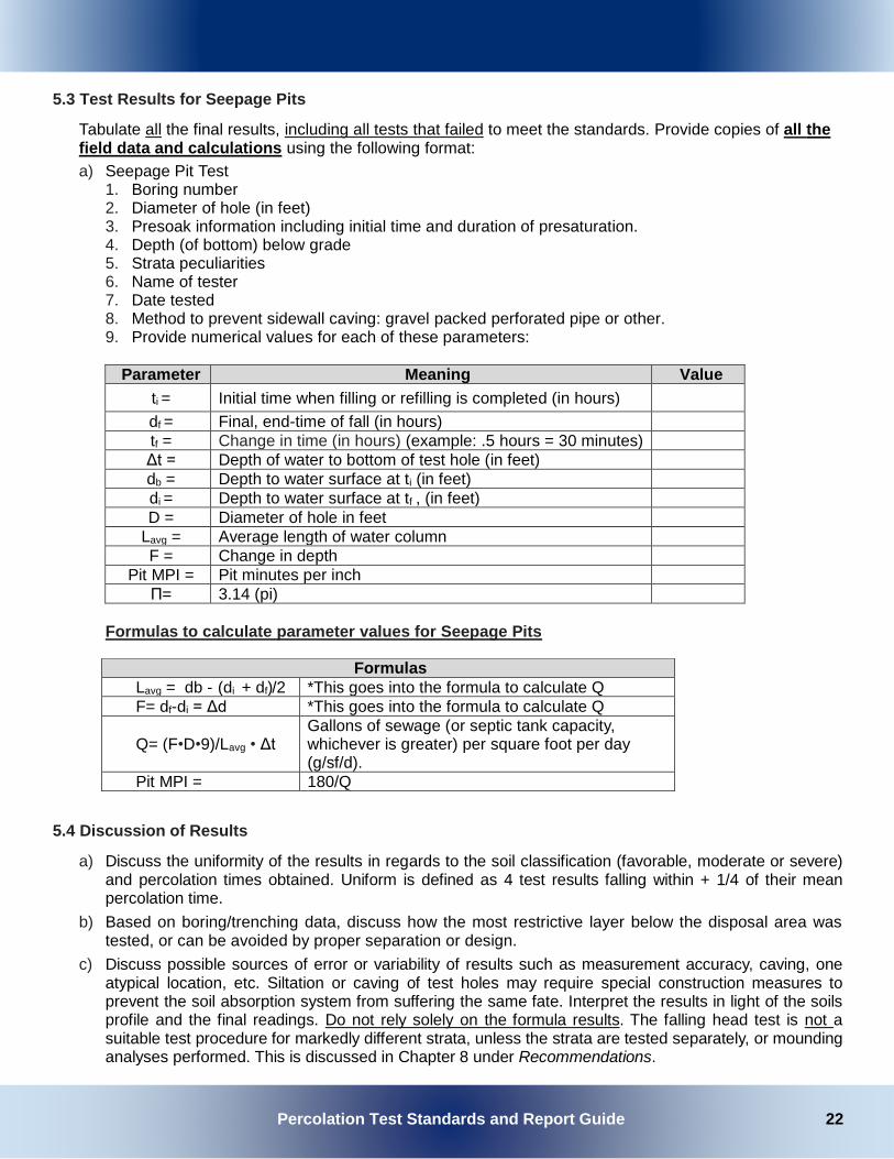
5.3 Test Results for Seepage Pits
Tabulate all the final results, including all tests that failed to meet the standards. Provide copies of all the field data and calculations using the following format:
a) Seepage Pit Test 1. Boring number 2. Diameter of hole (in feet) 3. Presoak information including initial time and duration of presaturation. 4. Depth (of bottom) below grade 5. Strata peculiarities 6. Name of tester 7. Date tested 8. Method to prevent sidewall caving: gravel packed perforated pipe or other. 9. Provide numerical values for each of these parameters:
Parameter Meaning Value
ti = Initial time when filling or refilling is completed (in hours)
df = Final, end-time of fall (in hours)
tf = Change in time (in hours) (example: .5 hours = 30 minutes)
Δt = Depth of water to bottom of test hole (in feet)
db = Depth to water surface at ti (in feet)
di = Depth to water surface at tf , (in feet)
D = Diameter of hole in feet
Lavg = Average length of water column
F = Change in depth
Pit MPI = Pit minutes per inch
Π= 3.14 (pi)
Formulas to calculate parameter values for Seepage Pits
5.4 Discussion of Results
a) Discuss the uniformity of the results in regards to the soil classification (favorable, moderate or severe) and percolation times obtained. Uniform is defined as 4 test results falling within + 1/4 of their mean percolation time.
b) Based on boring/trenching data, discuss how the most restrictive layer below the disposal area was tested, or can be avoided by proper separation or design.
c) Discuss possible sources of error or variability of results such as measurement accuracy, caving, one atypical location, etc. Siltation or caving of test holes may require special construction measures to prevent the soil absorption system from suffering the same fate. Interpret the results in light of the soils profile and the final readings. Do not rely solely on the formula results. The falling head test is not a suitable test procedure for markedly different strata, unless the strata are tested separately, or mounding analyses performed. This is discussed in Chapter 8 under Recommendations.
Formulas Lavg = db - (di + df)/2 *This goes into the formula to calculate Q
F= df-di = Δd *This goes into the formula to calculate Q
Q= (F•D•9)/Lavg • Δt
Gallons of sewage (or septic tank capacity, whichever is greater) per square foot per day (g/sf/d).
Pit MPI = 180/Q

Percolation Test Standards and Report Guide 23
Note: At least 75% of tests must show acceptable results. For example, if there is a failing test on a lot three additional acceptable tests must be shown on that lot. More than the minimum number of tests may be necessary to meet this requirement.
5.5 Design
General Criteria – Seepage Pits
a. For uniform soil units use Pit MPI, not Q, for averaging. b. Unless an area has been determined to have degraded groundwater by the RWQCB, there shall be a
minimum of 10 feet of original soil between the bottom of the soil absorption system and groundwater. c. Fairly uniform coarse-textured soils (silty sands (SM) or more coarse) shall not be used for seepage
pits when all of the following is present: • A “pit MPI” is less than 10, • Where a sieve analysis shows less than 15% fines passing the #200 U.S. standard sieve for a
thickness of 10 feet, and • Separation to groundwater is less than 40 feet.
d. Discuss the two year travel time evaluation for microbial contaminates for seepage pits greater than 20 feet below grade and the 600 foot separation from a public supply well cannot be met. See footnote 6 on setbacks, page 35. Basis for 100% passing - 3/8" sieve.
e. The design Q for seepage pits must be > 1.1 g/sf/day of sewage, but < 4 g/sf/day. Q’s greater than 4 g/sf/d will not be credited. Caving seepage pit test holes in coarse textured soils shall not be credited with rates greater than 3 g/sf/day.
5.6 Convert Q to Seepage Pit Design Rates
Seepage Pit Design Rate - Square feet (sf)/100 gallons septic tank capacity (gstc) or design flow (whichever is greater for larger flows).
1. Using the Q from the formula table in section 5.3, plug into the design rate formula
below: 1/Q X 100 = sf/100 gstc
2. To find depth below inlet use the formula below:
Design depth below inlet = septic tank capacity / (Q•D•π)
Note: Depth below inlet shall be limited to tested depth for uniform soils or by groundwater. For soils with different strata, limit effective sidewall to most permeable soils.

Percolation Test Standards and Report Guide 24
Chapter Six: Special Criteria
6.1 Guidelines for Determining the Number of Bedrooms
1. Once the living room, dining room, family room, kitchen, bathrooms, and utility rooms have been established, all other rooms shall be considered as potential sleeping rooms. Dens, libraries, studies, weight rooms, game rooms, sewing rooms, workshops, lofts, etc., shall be determined as bedrooms.
2. All other habitable rooms totaling at least seventy (70) square feet in size are to be considered bedrooms suitable for sleeping purposes, regardless of whether or not they contain closets or have access to a bathroom.
3. Rooms that open to a living room, dining room, family room, kitchen, or entry way, and have a single, un-obstructive opening (no doors) with a minimum 50% opening of the total wall space (minimum 6’ wide) with archways or other acceptable means shall not be considered as bedrooms.
4. Rooms that can only be accessed through another bedroom are to be considered part of that bedroom, such as master suite and not an additional bedroom.
5. In the case of an ambiguous situation, where it is not clear as to whether or not a room is a bedroom, the plans may be reviewed on a case-by-case basis by the Department.
6. Any cases, which will require the relocation or modification of doorways, are to be reviewed and approved by Building and Safety to address any structural considerations such as load bearing walls. This is to be done prior to approval or sign-off by EHS
Utilize the chart for minimum septic tank size based on number of bedrooms:
Number of Bedrooms Minimum Gallons of Septic Tank Capacity
1-2 750
3 1,000
4 1,200
5-6 1,500
6.2 Confluent Systems
a) If leach lines or pits serve a common OWTS for two or more units, add 30% more square footage according to CPC Table H 201.1 (1) Multiple dwelling units.
b) For laundromats, restaurants, and common systems serving mobile home parks or shopping centers (three or more retail shops): When a treatment tank volume is calculated for flows greater than 2000 gpd with Vol = .75 flow +1125. The dispersal area (square footage) will need to be multiplied by a factor of 2.5. Supplemental Treatment Systems are exempt from this requirement.
6.3 Credit for Alternating Fields
a) A credit of 10% reduction in square footage may be given for installation of alternating leach fields or seepage pits (unless the consultant specifies otherwise).
b) Single houses on lots less than 10,000 square feet in area or with leach fields on ground naturally sloping >30% with slope stability report may require alternating leach fields. The 100% expansion area may be used for one of the alternating leach fields.
c) Alternating systems may be considered when future access or critical soils are limiting factors.

Percolation Test Standards and Report Guide 25
6.4 Special Soil Conditions
a) Special soil conditions may require special consideration by the EHS and must be considered on a case-by-case basis, particularly in areas of high rainfall or in proximity to water sources.
b) San Bernardino County is known to be crisscrossed with flood control channels, water infiltration basins, percolation ponds, tunnels, and pipelines which supply water to water districts. Special care must be taken in siting the disposal systems. Check with EHS during notification.
c) Mottled soil - A mottled soil is marked with spots or blotches of contrasting color which is usually caused by saturation for some period during a normal year.
If this process has prevailed for significant periods over the recent geologic past, the resulting mottled soil colors can be readily observed.
Zones of seasonal or periodic soil saturation shall be estimated at the highest level of soil mottles. However, soil mottles can occur that are not due to zones of seasonal or periodic soil saturation; therefore, consult with EHS. The abundance, size, contrast and color of the soil mottles shall be described in the following manner: (except frozen soils and soils with rapid permeability).
Abundance shall be described as “few” if the mottled color occupies less than 2% of the exposed surface; “common” if the mottled color occupies from 2% to 20% of the exposed surface; or “many” if the mottled color occupies more than 20% of the exposed surface.
Size refers to the length of the mottle measured along the longest dimension and shall be described as fine if the mottle is less than 5 millimeters (mm); medium if the mottle is from 5-15 mm; or coarse if the mottle is greater than 15 mm.
Contrast refers to the difference in color between the soil mottle and the background color of the soil and is described as faint if the mottle is evident, but recognizable with close examination; distinct if the mottle is readily seen but not striking; or prominent if the mottle is obvious and one of the outstanding features of the horizon. The color(s) of the mottle(s) shall be indicated.
d) A leach line test hole 12 inches in diameter may be used only when the soil texture is coarse and it is not feasible to dig or bore a standard diameter test hole. The MPI obtained with this larger diameter hole must be multiplied by the correction factor contained in the leach lines formula.
e) Technical Modifications where sidewall soil materials may slough into the test hole during soaking, two techniques are applied: gravel packing and manual removal. For gravel packing, a perforated open-top cylinder is placed over the 2 inch layer of gravel at the bottom of the test hole. The cylinder is centered in the test hole. The 1 to 2 inch space between the sidewall of the hole and the cylinder is filled with loose, pea-sized gravel. The cylinder may be made out of a perforated piece of pipe, tin can, or hardware cloth. The measured water level drops must be corrected after calculating the effect of the gravel volume as stated in the leach line calculations.
6.5 Special Discharge Conditions
a) Local hydrogeological conditions may necessitate more separation of the sewage disposal system for protection of special resources (drinking water supply, recreation areas, water storage reservoirs, lakes, etc.). Refer to pages 41-43 of the LAMP.
b) Fractured bedrock (not including decomposed granite) and impervious strata are not suitable for sewage disposal. Impervious means stratum with perc times of >120 MPI.
c) The discharge of surface, rain, or other clear water into a sewage disposal system is prohibited.
d) Wastewater streams from water treatment devices such as; water softeners and contaminant (nitrate, arsenic, fluoride, uranium, iron, etc.) removal devices shall not be discharged into a domestic OWTS. Discharge shall be by physical or manual removal to an approved disposal site.
e) Discharge of toxic or hazardous chemicals to a domestic OWTS is prohibited. f) Industrial developments shall have individual monitoring ports for each unit connected to a

Percolation Test Standards and Report Guide 26
confluent sewage disposal system if there is a single owner of the development. Multi-owner industrial units (business park) shall have a separate system for each unit.
g) Sand filters and grease interceptors/traps/removal devices will be considered on a case-
by-case basis. High strength waste (>900 mg/L BOD5) shall require supplement
treatment and RWQCB approval.
h) Greywater systems are not covered by the LAMP and must comply with CPC Chapter 15.
6.6 Alternative Treatment Systems
If it is determined that a conventional OWTS cannot meet the requirements of the LAMP then an Alternative/Advanced Treatment System is required. A separate proposal for the Alternative/Advanced Treatment System must be submitted to this office for review along with the required review fee according to the current Fee Schedule.
The proposal must be prepared by a Qualified Professional and contain all of the following:
a) Alternative Treatment System Application.
b) A copy of the approved Percolation Report.
c) A description of the type of wastewater which will be discharged to the OWTS (i.e., domestic, commercial, high strength or industrial, see LAMP for complete definition).
d) List of all materials and products that will be used to construct the system. This includes:
1. All technical details/specifications, 2. Information on how the system will be maintained per manufacturer specification, 3. Procedures to ensure maintenance, repair, or replacement of critical items within 48 hours of
failure, and 4. Details of the visible or audible alarm, as well as a telemetric alarm that alerts the owner or
owner’s agent when there is a system failure or malfunction. e) Literature from the manufacturer showing the following:
1. Total nitrogen in the effluent from the alternative treatment system meets a minimum 50 percent reduction in total nitrogen when comparing the 30-day average influent to the 30-day average effluent,
2. The system can achieve a 30-day average effluent quality of 25 mg/L CBOD5 and 30 mg/L TSS or less.
3. Effluent has a fecal coliform bacteria concentration less than or equal to 200 Most Probable Number (MPN) per 100 milliliters (for systems near a body of water impaired for pathogens or where required by EHS or the RWQCB).
4. NSF certifications. f) Define which treatment mode will be used, if the system has multiple treatment modes.
g) Name and contact information for the approved service provider that will maintain the system.
h) Name of the Environmental Laboratory Accreditation Program certified laboratory where the effluent water samples will be analyzed. The following are required to be sampled: 1. Total Nitrogen
2. CBOD5
3. TSS
i) Effluent water sampling schedule or frequency. Effluent water sampling is required to be conducted quarterly for the first four quarters.
6.7 Alternative Sewage Disposal Options
a) Pump systems - All proposals for pumping shall be detailed in the PERC report and shall be subject to EHS and Building & Safety approval. A pump system may be approved when it is determined that the proposal is a hardship as defined. Hardship conditions include:

Percolation Test Standards and Report Guide 27
• Salvaging an existing structure when an adequate disposal area cannot be reached by gravity flow.
• Allowing new house construction on an existing lot when there is absolutely no other alternative to pumping. This hardship consideration will be based on reasonable site development. The following information is required for review:
- Percolation data
- Pump data
- Design of the pump chamber, to include a storage volume equal to 24 hours design flow, in the event of a power outage or a pump failure, or make provision for overflow to an adequately sized back-up gravity disposal area.
- Alarm system design
- Force main and backflow prevention design certified by American Water Works Association (AWWA) Grade II cross-connection specialist.
- Design of a receiving chamber at the disposal site which allows the simulation of gravity flow to the disposal system. In all cases, gravity flow to the septic tank is required, such that only settled effluent is pumped from the pump chamber. All components shall comply with the latest edition of the CPC and California Building Code (CBC) standards.
b) Where site conditions are such that individual septic systems are not feasible for the proposed development, the use of a multiple ownership septic system may be used, complying with the San Bernardino County Code, Title 3, Chapter 8, Article 7, and may require RWQCB Water Discharge Requirements.
c) Utilization of supplemental treatment systems and/or alternative dispersal systems may be utilized on or off site for those developments which can comply with the LAMP. A percolation report will be required for all developments. Siting of the system and the design of the treatment system shall meet EHS and Building & Safety standards on a case by case basis. The alternative treatment system shall be under the control of: 1) a public entity or 2) serviced on a regular basis by qualified, certified service provider. The conditions of approval and any required monitoring shall be part of the property’s recorded deed. An annual permit to operate will be required. See appendix J for NSF International ATU reference.
d) If a site is unsuitable for standard leach lines or seepage pits, see Appendix J: Suggested References for links to guidelines for designing mounds, Evapotranspiration systems or drip systems. EHS will follow the State Guidelines contained therein.

Percolation Test Standards and Report Guide 28
Chapter Seven: Plot Plan California Plumbing Code
7.1 Plot system and 100% expansion area, show existing and potential structures, wells, streams, etc. Include
contours, significant vegetation (including trees), rock outcropping, location of all borings and tests, and the
proposed building pad.
Draw tested property to scale: Single Family Home, Small Commercial………….. Minimum 1" = 30' Parcel Map, Subdivision, Large Commercial……... Minimum 1" = 40'
7.2 For lot sales zoned for single family homes (lot sale subdivisions) show a hypothetical system for a five (5)
bedroom home on each and every lot; if zoned for multi-unit development, show a hypothetical system sufficient for the effluent discharged by an average of three bedrooms per unit. If wells are proposed for each lot, show that every lot can be built meeting all set-back requirements.
7.3 Where grading is expected, include original and finished elevations. If the grading plan was prepared by others, comment as it regards the recommendations set forth in the report. If grading is unknown, include qualifying statements in area(s) for the primary and expansion systems (see 3.1).
7.4 The proposed dwelling/development shall be located so that the initial subsurface sewage disposal system
and the required 100% expansion area shall function by gravity flow unless otherwise approved.
7.5 All designed system’s construction details are subject to review by EHS and approval by Building & Safety.
Minimum conventional construction details are to be found in the currently adopted California Plumbing
Code. Advanced Treatment system details must conform to the Local Agency Management Program.
7.6 Commercial projects: The required capacity of the septic tank is based upon the project and must comply
with Table H 201.1(1) (for fixture unit count), Table H 201.1(2) (for estimated waste/sewer flow rates),
section 422.1 (fixture units) of the CPC and Table 1004.1.2 (for occupancy) of the CBC.

Percolation Test Standards and Report Guide 29
Chapter Eight: General Recommendations
The following recommendations are provided to assist in preparing a Soil Percolation Report. 8.1 State whether each lot has sufficient area to support an individual sewage disposal system that will meet
EHS standards for the use intended. Include a qualifying statement if swimming pools, building expansions, etc. are or may be allowed; also if grading must be restricted, or if grading plans must be reviewed prior to grading, and installation inspected after grading by soils consultant, or if special construction techniques are required.
8.2 Discuss sewage mounding if lots are to be developed commercially or industrially with flows of 1500 gpd or greater and/or as determined necessary under Seepage Pit Design. In addition, for commercial and industrial discharges, discuss the OWTS ability to adequately treat harmful waste constituents prior to entering the groundwater if other than sanitary wastes may be discharged. Indicate if a special treatment process study should be done after the exact nature of the discharge(s) has been determined. Provide source of sewage mounding modeling.
EHS recommends that preparers provide the following information to property owners.
8.3 The EHS septic system handout Taking Care of Your Septic System can be obtained by the owner/developer, or a copy can be provided in submitted percolation report for conventional OWTS.

Percolation Test Standards and Report Guide 30
APPENDIX

Percolation Test Standards and Report Guide 31
Textural Triangle Defining Twelve Textural Classes of the USDA
(Illustrated For A Sample Containing 37% Sand, 45%Silt, And 18% Clay)
40 30 20 10 0 100 90 80 70 60 50
Appendix Figure A: Textural Triangle

MATERIAL TYPES CRITERIA FOR ASSIGNING SOIL GROUP NAMES GROUP
SYMBOL GROUP NAME
CO
AR
SE G
RAI
NED
SO
ILS
MO
RE
THA
N 5
0% R
ETA
INED
ON
OR
AB
OVE
N
O. 2
00 (0
.075
MM
) SIE
VE
GRAVEL > 50% OF COARSEFRACTIONRETAINED ON NO.4(4.75 MM) SIEVE
CLEAN GRAVEL <5% SMALLER THAN NO.200 SIEVE
CU ≥ 4 AND 1 ≤ CC ≤ 3 GW WELL-GRADED GRAVEL, FINE TO COARSE GRAVEL
CU < 4 AND/OR CC < 1 OR CC > 3 GP POORLY GRADED GRAVEL
GRAVEL WITH >12% FINES
FINES CLASSIFY AS ML OR MH GM SILTY GRAVEL
FINES CLASSIFY AS CL OR CH GC CLAYEY GRAVEL SAND ≥ 50% OF COARSE FRACTION PASSES NO.4 (4.75 MM) SIEVE
CLEAN SAND CU ≥ 6 AND 1 ≤ CC ≤ 3 SW WELL-GRADED SAND, FINE TO COARSE SAND
CU < 6 AND/OR CC < 1 OR CC > 3 SP POORLY GRADED SAND SAND WITH >12% FINES
FINES CLASSIFY AS ML OR MH SM SILTY SAND FINES CLASSIFY AS CL OR CH SC CLAYEY SAND
FINE
GRA
INED
SO
ILS
50%
OR
MO
RE P
ASSI
NG T
HE
NO
.200
(0.0
75 M
M) S
IEVE
SILT AND CLAY LIQUID LIMIT < 50
INORGANIC PI > 7 AND PLOTS ON OR ABOVE "A" LINE CL CLAY OF LOW PLASTICITY, LEAN CLAY
PI < 4 AND PLOTS BELOW "A" LINE ML SILT ORGANIC LIQUID LIMIT—OVEN DRIED < 0.75 OL ORGANIC CLAY
LIQUID LIMIT—NOT DRIED OL ORGANIC SILT SILT AND CLAY LIQUID LIMIT ≥ 50
INORGANIC PI PLOTS ON OR ABOVE "A" LINE CH CLAY OF HIGH PLASTICITY, FAT CLAY
PI PLOTS BELOW "A" LINE MH SILT OF HIGH PLASTICITY, ELASTIC SILT
ORGANIC LIQUID LIMIT—OVEN DRIED < 0.75 OH ORGANIC CLAY LIQUID LIMIT - NOT DRIED OH ORGANIC SILT
HIGHLY ORGANIC SOILS PT PEAT
PENETRATION RESISTANCE (RECORDED AS BLOWS/0.5FT) SAND & GRAVEL SILT & CLAY
RELATIVE DENSITY
BLOWS/FOOT CONSISTENCY BLOWS/FOOT COMPRESSIVE STRENGTH (TSF)
VERY LOOSE 0 - 4 VERY SOFT 0 - 2 0 - 0.25 LOOSE 4 - 10 SOFT 2 - 4 0.25 - 0.50 MEDIUM DENSE
10 - 30 FIRM 4 - 8 0.50 - 1.0
DENSE 30 - 50 STIFF 8 - 15 1.0 - 2.0 VERY DENSE OVER 50 VERY STIFF 15 - 30 2.0 - 4.0
HARD OVER 30 OVER 4.0 * Number of blows of 140lb hammer falling 30in to drive a 2in O.D (1-3/8 in I.O) split barrel.
Sample the last 12in of a 15in drive (ASTM-1586 standard penetration test).
ADDITIONAL TESTS CA- CHEMICAL ANALYSIS (CORROSIVITY) (200)- (WITH PASSING NO. 200 SIEVE) CD- CONSOLIDATED DRAINED TRIAXIAL SW- SWELL TEST CN- CONSOLIDATION TC- CYCLIC TRIAXIAL CU- CONSOLIDATED UNDRAINED TRIAXIAL TV- TORVANE SHEAR DS- DIRECT SHEAR UC- UNCONFINED COMPRESSION PP- POCKET PENETROMETER (TSF) (1.5)- (WITH SHEAR STRENGTH IN KSF) (3.0)- (WITH SHEAR STRENGTH KSF) UU- UNCONSOLIDATED UNDRAINED TRIAXIAL RV- R-VALUE WA- WASH ANALYSIS SA- SIEVE ANALYSIS % PASSING #200 SIEVE
- WATER LEVEL (WITH DATE OF) MEASUREMENT(200%)- (WITH % PASSING NO. 200 SIEVE)
UNIFIED SOIL CLASSIFICATION (ASTM D-2487-98)
Percolation Test Standards and Report Guide 32
A ppendix Figure B: Unified Soil Classification

Percolation Test Standards and Report Guide 33
Major Divisions
1 2
Letter
3
Symbol Name
6 Hatching
4 Color
5
COARSE GRAINED
SOILS
GRAVEL AND
GRAVELY SOILS
GW
RED
Well-graded gravels or gravel-sand mixtures, little or no fines
GP Poorly-graded gravels or gravel-
sand mixtures, little or no fines
GM
YELLOW
Silty gravels, gravel-sand-silt mixtures
GC Clayey gravels, gravel-sand-clay
mixtures
SAND AND
SANDY SOILS
SW
RED
Well-graded sands or gravelly sands, little or no fines
SP Poorly-graded sands or gravelly
sands, little or no fines
SM
YELLOW
Silty sands, sand-silt mixtures
SC
Clayey sands, sand-silt mixtures
FINE GRAINED
SOILS
SILTS AND
CLAYS LL<50
ML
GREEN
Inorganic silts and very fine sands, rock flour, silty, or clayey fine sands or clayey silts with slight plasticity
CL Inorganic clays of low to medium
plasticity, gravelly clays, sandy clays, silty clays, lean clays
OL Organic silts and organic silt-
clays if low plasticity
SILTS AND CLAYS LL>50
MH
BLUE
Inorganic silts, micaceous or diatomaceous fine sandy or silty soils, elastic silts
CH Inorganic clays of high plasticity,
fat clays
OH Organic clays of medium to high
plasticity, organic silts
HIGHLY ORGANIC SOILS
Pt
ORANGE Peat and other highly organic soils
Appendix Figure B continued

Percolation Test Standards and Report Guide 34
Soil Texture (per the USDA soil classification
system
Soil Structure Shape
Grade
Maximum Soil Application Rate (gallons per day
per square foot) 1
Coarse Sand, Sand, Loamy Coarse Sand, Loamy Sand
Single Grain
Structureless
0.8
Fine Sand, Very Fine Sand, Loamy Fine
Sand, Loamy Very Fine Sand
Single Grain
Structureless
0.4
Coarse Sandy Loam, Sandy
Loam
Massive Structureless 0.2
Platy Weak 0.2
Moderate, Strong Prohibited
Prismatic Blocky Granular
Weak 0.4
Moderate , Strong 0.6
Fine Sandy Loam, Very Fine
Sandy Loam
Massive Structureless 0.2
Platy Weak, Moderate
Strong Prohibited
Prismatic, Blocky, Granular
Weak 0.2
Moderate, Strong 0.4
Loam
Massive Structureless 0.2
Platy Weak, Moderate
Strong Prohibited
Prismatic, Blocky, Granular
Weak 0.4
Moderate, Strong 0.6
Silt Loam
Massive Structureless Prohibited
Platy Weak, Moderate
Strong Prohibited
Prismatic, Blocky, Granular
Weak 0.4
Moderate, Strong 0.6
Sandy Clay Loam, Clay
Loam, Silty Clay Loam
Massive Structureless Prohibited
Platy Weak, Moderate
Strong Prohibited
Prismatic, Blocky, Granular
Weak 0.2
Moderate, Strong 0.4
Sandy Clay, Clay, or Silty
Clay
Massive Structureless Prohibited
Platy Weak, Moderate
Strong Prohibited
Prismatic, Block, Granular
Weak Prohibited
Moderate, Strong 0.2
Appendix Figure C: Design Soil Application Rates

Percolation Test Standards and Report Guide 35
The minimum requirements for the installation of new sewage disposal systems for either new or existing structures shall generally be as follows: A. Minimum Separations
1. Septic tank to:
2. Soil absorption system to:
Septic Tank to: Feet
Water supply well 100
Buildings or structures 5
Property line adjoining private property 5
Perennial streams2 50
Ephemeral streams3 50
Large trees4 10
Seepage pits or disposal fields 5
Private domestic water lines (building service lines) 5
Public domestic water lines (water purveyor’s line) 25
Groundwater 5
Soil Absorption System to: Feet
Domestic supply well - 100, 150, or 200 ft. depending on whether system has a: • Leaching field • Seepage pit • Any system discharging 5,000 gallons/day or more
100 150 200
Public Water Supply Wells - Dispersal system: • Does not exceed 10 feet • Exceeds 10 to 20 feet • Exceeds 20 feet6
150 200 600
Building or structures 8
Property line adjoining private property (leach lines) 5
Property line adjoining private property (seepage pits) 8
Colorado River/Mojave River 200
Septic tank 5
Distribution box 5
Private domestic water line (building service line) 5
Public domestic water line (water purveyor’s line) 25
Seepage pit 10
Ground surface on sloping ground (When disposal fields and/or seepage pits are installed in sloping ground, the minimum horizontal distance between any part of the leaching system and ground surface shall be 15 feet.) Also see page 29.
15
Lakes, water reservoirs 200
Appendix D: Liquid Waste Disposal Systems

Percolation Test Standards and Report Guide 36

Percolation Test Standards and Report Guide 37
3. The minimum separations listed herein are largely derived from the California Plumbing Code. In some cases, additions or changes have been made in order to adequately protect water quality and the public health. Where differences exist, the greater separation prevails unless specifically waived for cause by EHS.
Footnotes:
1 Includes porches and steps whether covered or uncovered, breezeways, roofed porte-cocheres, roofed patios, carports, covered walls, covered driveway, and similar structures or appurtenances.
2 A listing of perennial streams will be maintained by EHS. See pages 37-38.
3 An ephemeral stream/drainage course is any stream not listed as a perennial stream by the EHS (see Footnote 2). To determine where the setback restrictions should be applied, the USGS Maps are used as a guide. If a stream is designated on the USGS Map by a blue dash/dotted line, the setback requirements must be met. If not shown, but there is obvious visual evidence of water flow, the setback is determined by the topography and the geology of the proposed site, but is not less than 25'. Distances are measured from the edge of the channel or assumed 0 to 100 year flow.
4 Any tree with a trunk diameter of one foot or more within 5 feet of the system that will not be removed during construction.
5 The highest known level to which groundwater is known to have occurred rather than the level at the time when testing occurred.
6 Dispersal systems which exceed 20 feet in depth and are located within 600 feet of a municipal well (any public water supply well) will be required to have the consultant evaluate the two year travel time for microbial contaminants to determine required setback. In no case will the setback to less than 200 feet.

Percolation Test Standards and Report Guide 38
Any portion of the disposal field located to the top of a cut or on sloping ground shall maintain a 15 foot horizontal distance from daylight to any portion of the leach lines or leach bed. The table gives the minimum cover required versus the percent of slope in the area of the disposal field to meet the 15 foot requirement. This table also gives a factor “f” by which to increase the length of the trench due to the assumed loss in evapotranspiration caused by the added cover.
Slope of the Ground in the Area of
the Disposal System
Minimum Cover Over the Drain
Lines
f
5% 1.00 ft 1.0
10% 1.50 ft. 1.0
15% 2.25 ft 1.0
20% 3.00 ft. 1.0
25% 3.75 ft. 1.1
30% 4.50 ft. 1.2
35% 5.25 ft. 1.3
40% 6.00 ft. 1.4
45% 7.00 ft. 1.5
Slopes greater than 30% require a slope stability report and will be reviewed by the county geologist.
Note: If, for design purposes, additional cover is required over drain lines (e.g.; below fill or a restrictive strata with >120 MPI), the cover factor is still applicable.
Appendix F: Special Considerations for Absorption Field Placement in Sloping Ground
1. If ground slope is > 30%, any portion of an absorption field (except solid pipe) shall be a minimum of 10
feet (horizontally) from the downslope property line(s). It is the report preparer’s responsibility to certify that this minimum is applied or expanded if the slope is less than or equal to 30%, but the soil conditions are such that a basement or curtain drain already built 5 feet downslope from the lower property line(s) may be affected by sewage effluent. Show setback on plot.
2. The minimum horizontal distance between any portion of an absorption field (except solid pipe) and an exposed downward sloping impermeable stratum or bedrock in “cut” slope shall be 50 feet. It is the report preparer’s responsibility to make recommendations so that systems do not daylight. It is the owner/contractor(s) responsibility to install systems per the recommendations. The consultant may wish to inspect installations to be assured that recommendations are followed. Consultants may choose to make this a requirement of approval. Upon presentation of pertinent engineering data, the REHS may stipulate this requirement.
Appendix E: Daylight Requirements

Percolation Test Standards and Report Guide 39
If gravel packing was used, correct rates for the effect of the gravel volume. Show in detail measurements of the gravel volume and the calculations. The following method for calculating percent gravel voids in the field is recommended:
1. Fill 23½ oz. cylindrical tin can “A” with gravel. The gravel should be loose and not compacted, like the gravel in the test hole. Do not shake the can.* If the gravel is fine (pea size), fill with water and then drain thoroughly.
2. Fill another identical can “B” with water;
3. Pour can “B” into can “A” until water barely drips out of its rim (no spillages).
Percent gravel void is equal to height of water missing in B divided by total height of can, multiplied by 100. Add formula correction factor to seepage pit or leach line design as a multiplier.
Correction Factor Formula = [1 + P (C2 - 1)] / C2 C = r2 / r1 r2 = radius of hole r1 = radius of pipe P = % of voids
Another method for gravel packing corrections is by weighing the can with gravel, with gravel + water and with water using the formula below. This method does not require two identical cans. 1. A = weight of empty can 2. B = weight of the can filled with water 3. Empty water from can and fill with gravel (wet or dry as in other method) 4. C = weight of can with gravel 5. Fill gravel-packed can with water to top; 6. D = weight of can with water and gravel 7. Calculate the gravel correction factor using the following equation
(D–C) P = [B–A]
Note: I f during field testing the gravel in the test hole is observed to compact, shake the can.
Appendix G: Gravel Packing Corrections
Appendix I: Perennial Streams of San Bernardino CountyAppendix H: Gravel Packing Corrections
Appendix H: Gravel Packing Corrections
Appendix I: Perennial Streams of San Bernardino CountyAppendix H: Gravel Packing Corrections

Percolation Test Standards and Report Guide 40
The following list of streams has been provided to the RWQCB. These are the streams which the RWQCB consider to be wholly or in part perennial. The list may be amended from time to time in order to reflect new information as it becomes known to EHS.
A. California Regional Water Quality Control Board, Lahontan Region (Regional Board # 6) 1. East Fork of the West Fork of the Mojave River 2. Seeley Canyon Creek 3. Houston Creek 4. Deep Creek 5. Holcomb Creek 6. Hooks Creek 7. Shale Creek 8. Crab Creek 9. Little Bear Creek (Lake Arrowhead Dam to confluence with Deer Creek) 10. Salt Creek (North of Baker, California) 11. Heath Canyon Creek 12. Swarthout Creek 13. Sheep Creek (North of Highway 2)
B. California Regional Water Quality Control Board Colorado River Basin Region (Regional Board # 7) 1. Colorado River 2. Whitewater River 3. San Gorgonio River 4. Pinto Creek 5. Copper Basin Creek 6. Arrastre Creek
C. California Regional Water Quality Control Board, Santa Ana Region (Regional Board # 8) 1. Santa Ana River - Reach 6 (Above confluence with Bear Creek)
a. Deer Creek b. Hamilton Creek c. Wildhorse Creek d. Cienaga Seca Creek e. Coon Creek f. Fish Creek g. Lost Creek h. South Fork - Santa Ana River i. Frog Creek j. Barton Creek (east and west forks) k. Forsee Creek l. Schneider Creek
m. Gold Creek
2. Mill Creek (above upper powerhouse)
a. Mountain Home Creek b. Monkey Face Creek c. Alger Creek d. Falls Creek e. Vivian Creek
3. Oak Glen Creek (above Oak Glen) a._Birch Creek
4. Bear Creek a. North Fork - Bear Creek b. Grout Creek
Appendix H: Perennial Streams of San Bernardino County
Appendix J: Suggested ReferencesAppendix I: Perennial Streams of San Bernardino County
Appendix I: Perennial Streams of San Bernardino County
Appendix J: Suggested ReferencesAppendix I: Perennial Streams of San Bernardino County

Percolation Test Standards and Report Guide 41
c. Caribou Creek d. Rathbone Creek e. Metcalf Creek f. Kidd Creek g. Siberia Creek
5. Lytle Creek (above upper powerhouse) a. Middle Fork - Lytle Creek
6. Devil Canyon Creek (east and west forks above power plant)
7. Cajon Creek (above Keenbrook)
8. Waterman Canyon Creek
9. City Creek (above gaging stations) a. West Fork - City Creek b. East Fork - City Creek c. Middle Fork - City Creek
10. Plunge Creek (above gaging stations) a. Little Mill Creek b. Fredalba Creek
11. Alder Creek (tributary to Santa Ana Reach 5) a. Middle Fork - Alder Creek b. Hemlock Creek c. Keller Creek
12. East Twin Creek (above gaging stations) a. Strawberry Creek
13. East Etiwanda Creek (within National Forest)
14. Day Canyon Creek (above gaging station)
15. Cucamonga Creek (above gaging station)
16. San Antonio Creek (1 mile above community of Mt. Baldy) a. Ice House Canyon Creek
17. Chino Creek (from confluence with Santa Ana River to Pine Avenue)
18. Carbon Canyon

Percolation Test Standards and Report Guide 42
California Plumbing Code (CPC) – San Bernardino County follows the guidelines as stated in this Code. http://www.iapmo.org/Pages/2016CaliforniaPlumbingCode.aspx Environmental Protection Agency (EPA) Guidelines - This site has recommendations on how to take care of a septic system. https://www.epa.gov/sites/production/files/2015-6/documents/2004_07_07_septics_septic_2002_osdm_all.pdfs Evapotranspiration Guidelines - State of California Water Resource Control Board (SWRCB) has guidelines on evapotranspiration systems. https://www.waterboards.ca.gov/publications_forms/publications/general/docs/evapotranspiration-1980.pdf Geoflow drip irrigation - EHS follows the guidelines as outlined on this site for drip irrigation. http://geoflow.com/wp-content/uploads/2017/02/Geoflow-Design-Manual-Oct-2007.pdf AB885 SWRCB OWTS policy http://www.waterboards.ca.gov/water_issues/programs/owts/docs/owts_policy.pdf National Sanitation Foundation International Advanced Wastewater Treatment System- List of manufactures
that meet Standard 40, 245, or 350. http://info.nsf.org/Certified/Wastewater/ San Bernardino County Local Agency Management Program (LAMP) - The program for the review and approval of Onsite Wastewater Treatment Systems (OWTS). http://wp.sbcounty.gov/dph/wp-content/uploads/sites/7/2017/08/San-Bernardino-County-LAMP.pdf State Mound System Guidelines (1998) – The SWRCB guidelines on mound systems. https://www.waterboards.ca.gov/publications_forms/publications/general/docs/guidelines-mound-systems-1980.pdf SWRCB - Provides links to all nine of the region basin plans. San Bernardino County is within Regions 6, 7, and 8 for a map refer to the LAMP. https://www.waterboards.ca.gov/plans_policies/ EPA- Design manuals for OWTS that are useful in the planning and implementation of OWTS systems. United States Environmental Protection Agency - 1980 Design Manuals- https://www.epa.gov/sites/production/files/2015-06/documents/septic_1980_osdm_all.pdf United States Environmental Protection Agency - 2002 Design Manuals- Onsite Wastewater Treatment and Disposal Systems.
Appendix I: Suggested References
Appendix J: Suggested References
Appendix J: Suggested References
Appendix J: Suggested References

San Bernardino County Public Health
Environmental Health Services
385 N Arrowhead Ave. 2nd floor
San Bernardino, CA 92415
1-800-442-2283 TDD (909) 387-4859
http://wp.sbcounty.gov/dph/programs/ehs/