
PERATOR SAFETY SERVICE MANUAL - MBW€¦ · Checking Percussion System Oil Refer to Lower Unit...
25
OPERATOR’S SAFETY AND SERVICE MANUAL MBW, Inc. 250 Hartford Rd • PO Box 440 Slinger, WI 53086-0440 Phone: (262) 644-5234 Fax: (262) 644-5169 Email: [email protected] Website: www.mbw.com MBW (UK) Ltd. Units 2 and 3 Cochrane st Bolton BL3 6BN, England Phone: 44 (0) 01204 387784 Fax: 44 (0) 01204 387797 MBW France S.A.R.L Z.A. d’Outreville 5 rue Jean Baptiste Néron, 60540 BORNEL, France Phone: 33 (0) 3 44 07 15 96 Fax: 33 (0) 3 44 07 41 28 L17786 / 5.11.M ©MBW, Inc. 2011 Printed in the USA AIRAMMER This manual covers the following serial numbers and higher for each model listed: AR56/AR57 . . . . . . . . . . . . . . . . 570059 RAMMERS
Transcript of PERATOR SAFETY SERVICE MANUAL - MBW€¦ · Checking Percussion System Oil Refer to Lower Unit...

OPERATOR’S SAFETY AND SERVICE MANUAL
MBW, Inc.250 Hartford Rd • PO Box 440Slinger, WI 53086-0440Phone: (262) 644-5234Fax: (262) 644-5169Email: [email protected]: www.mbw.com
MBW (UK) Ltd.Units 2 and 3 Cochrane stBolton BL3 6BN, EnglandPhone: 44 (0) 01204 387784Fax: 44 (0) 01204 387797
MBW France S.A.R.LZ.A. d’Outreville5 rue Jean Baptiste Néron,60540 BORNEL, FrancePhone: 33 (0) 3 44 07 15 96Fax: 33 (0) 3 44 07 41 28
L17786 / 5.11.M©MBW, Inc. 2011Printed in the USA
AIRAMMERThis manual covers the following serial numbersand higher for each model listed:AR56/AR57 . . . . . . . . . . . . . . . . 570059
RAMMERS

TABLE OF CONTENTS
Safety Information . . . . . . . . . . . . . . . . . . . . . . 1Introduction . . . . . . . . . . . . . . . . . . . . . . . . . . . . . . . . . 1
Safety Precautions . . . . . . . . . . . . . . . . . . . . . . . . . . . 1
Safety Decals . . . . . . . . . . . . . . . . . . . . . . . . . . . . . . . 1
Specifications. . . . . . . . . . . . . . . . . . . . . . . . . . 3
Operation . . . . . . . . . . . . . . . . . . . . . . . . . . . . . 4Introduction . . . . . . . . . . . . . . . . . . . . . . . . . . . . . . . . . 4
Before Starting & Operating . . . . . . . . . . . . . . . . . . . . 4
Motor Lubrication . . . . . . . . . . . . . . . . . . . . . . . . . . . . 4
Connecting to Air Compressor . . . . . . . . . . . . . . . . . . 4
Operating . . . . . . . . . . . . . . . . . . . . . . . . . . . . . . . . . . 4
Motor Icing . . . . . . . . . . . . . . . . . . . . . . . . . . . . . . . . . 4
Stopping Airammer . . . . . . . . . . . . . . . . . . . . . . . . . . . 5
Maintenance . . . . . . . . . . . . . . . . . . . . . . . . . . . 6Maintenance Schedule . . . . . . . . . . . . . . . . . . . . . . . . 6
Fluid Levels. . . . . . . . . . . . . . . . . . . . . . . . . . . . . . . . . 6
Checking Percussion System Oil . . . . . . . . . . . . . . . . 6
Changing Percussion System Oil . . . . . . . . . . . . . . . . 6
Service . . . . . . . . . . . . . . . . . . . . . . . . . . . . . . . 7Torque Chart. . . . . . . . . . . . . . . . . . . . . . . . . . . . . . . . 7
Service Tools . . . . . . . . . . . . . . . . . . . . . . . . . . . . . . . 7
General . . . . . . . . . . . . . . . . . . . . . . . . . . . . . . . . . . . . 7
Handle Removal . . . . . . . . . . . . . . . . . . . . . . . . . . . . . 7
Motor Removal . . . . . . . . . . . . . . . . . . . . . . . . . . . . . . 7
Pinion Removal . . . . . . . . . . . . . . . . . . . . . . . . . . . . . 7
Gearbox Removal . . . . . . . . . . . . . . . . . . . . . . . . . . . 8
Gearbox Disassembly . . . . . . . . . . . . . . . . . . . . . . . . 8
Cover Removal. . . . . . . . . . . . . . . . . . . . . . . . . . . . . . 8
Crank Gear Removal . . . . . . . . . . . . . . . . . . . . . . . . . 8
Breather Removal . . . . . . . . . . . . . . . . . . . . . . . . . . . 9
Lower Unit Disassembly. . . . . . . . . . . . . . . . . . . . . . . 9
Guide Tube and Bellows . . . . . . . . . . . . . . . . . . . . . . 9
Springbox . . . . . . . . . . . . . . . . . . . . . . . . . . . . . . . . . . 9
Gearbox Assembly . . . . . . . . . . . . . . . . . . . . . . . . . . . 9
Crank Gear Assembly . . . . . . . . . . . . . . . . . . . . . . . . 9
Pinion Assembly. . . . . . . . . . . . . . . . . . . . . . . . . . . . 10
Motor Assembly . . . . . . . . . . . . . . . . . . . . . . . . . . . . 10
Cover Assembly . . . . . . . . . . . . . . . . . . . . . . . . . . . . 10
Lower Unit Assembly . . . . . . . . . . . . . . . . . . . . . . . . 10
Gearbox/Lower Unit Assembly. . . . . . . . . . . . . . . . . 10
Handle Assembly . . . . . . . . . . . . . . . . . . . . . . . . . . . 11
Part Replacement Cycles and Tolerances . . . . . . . . 11
Replacement Parts . . . . . . . . . . . . . . . . . . . . . 13Gearbox Assembly . . . . . . . . . . . . . . . . . . . . . . . . . . 14
Lower Unit Assembly . . . . . . . . . . . . . . . . . . . . . . . . 16
Handle Assembly . . . . . . . . . . . . . . . . . . . . . . . . . . . 18
Valve Assembly . . . . . . . . . . . . . . . . . . . . . . . . . . . . 20
Warranty- Airammer (AR56/AR57) . . . . . . . . 22

This page intentionally left blank.

- 1 -
SAFETY INFORMATION
IntroductionThis Safety Alert Symbol is used to call attentionto items or operations which may be dangerousto those operating or working with thisequipment. The symbol can be found
throughout this manual and on the unit. Please read thesewarnings and cautions, along with all decals, carefullybefore attempting to operate the unit. Make sure everyindividual who operates or works with this equipment isfamiliar with all safety precautions.
WARNING
GENERAL WARNING. Indicates informationimportant to the proper operation of theequipment. Failure to observe may result indamage to the equipment and/or severe bodilyinjury or death.
CAUTION
GENERAL CAUTION. Indicates informationimportant to the proper operation of theequipment. Failure to observe may result indamage to the equipment.
Safety PrecautionsLETHAL EXHAUST GAS: An internalcombustion engine discharges carbonmonoxide, a poisonous, odorless, invisiblegas. Death or serious illness may result ifinhaled. Operate only in an area with properventilation. NEVER OPERATE IN ACONFINED AREA!
DANGEROUS FUELS: Use extreme cautionwhen storing, handling and using fuels, asthey are highly volatile and explosive in vaporstate. Do not add fuel while engine is running.Stop and cool the engine before adding fuel.DO NOT SMOKE!
SAFETY GUARDS: It is the owner'sresponsibility to ensure that all guards andshields are in place and in working order.
IGNITION SYSTEMS: Breakerless, magneto,and battery ignition systems can cause severeelectrical shocks. Avoid contacting theseunits or their wiring.
SAFE DRESS: Do not wear loose clothing,rings, wristwatches, etc. near machinery.
NOISE PROTECTION: Wear OSHA specifiedhearing protection devices.
EYE PROTECTION: Wear OSHA specifiedeye shields, safety glasses, and sweat bands.
FOOT PROTECTION: Wear OSHA specifiedsteel-tipped safety shoes.
HEAD PROTECTION: Wear OSHA specifiedsafety helmets.
DUST PROTECTION: Wear OSHA specifieddust mask or respirator.
OPERATOR: Keep children and bystandersoff and away from the equipment.
REFERENCES: For details on safety rules and regulationsin the United States, contact your local Occupational Safetyand Health Administration (OSHA) office. Equipmentoperated in other countries must be operated and servicedin accordance and compliance with any and all safetyrequirements of that country. The publication of thesesafety precautions is done for your information. MBW doesnot by the publication of these precautions, imply or in anyway represent that these are the sum of all dangers presentnear MBW equipment. If you are operating MBWequipment, it is your responsibility to insure that suchoperation is in full accordance with all applicable safetyrequirements and codes. All requirements of the UnitedStates Federal Occupational Safety and HealthAdministration Act must be met when operated in areas thatare under the jurisdiction of that United States Department.
Safety DecalsCarefully read and follow all safety decals. Keep them ingood condition. If decals become damaged, replace asrequired. If repainting the unit, replace all decals. Decalsare available from authorized MBW distributors. Order thedecal set listed on the following page(s).

- 2 -
12203
CAUTIONRead the Operating Instructions before operating this piece of equipment.
Keep unauthorized and untrained people away from this equipment.
ROTATING & MOVING PARTS!Make sure all guards and safety devices are in place.
Wear approved hearing protection, foot protection, eye protection and head protection.
SHUT OFF the motor before servicing or cleaning.
Failure to comply could result in serious bodily injury.
STOP
�����
�������
�� ������� ���
�����
���������������
������������������������
DANGER
Compressed spring could cause severe injury.
See manual for disassembly instructions.
La resorte comprimida podría causar la
herida severa. Consulte el libro para
ver el desmontaje correcto.
PELIGRO
0132
6
CAUTIONMachine is top heavy and could fall if not lifted from this bar.
17779
AIRAMMER= #120 (54kg)
Safety Decals (Decal Set #12101)
13535
13538
12203
01326
17779
13534�����
�������������� ����������������!"$�%&''*+�-�%�������������
�����
����'���!"$�%&''*+�-�%��/!*/�������6'$�%%�$�
����8&��:��!��&!��$�-!�;*�����%�!$��6!�-"���
����-��<�"$!66�$�'$�%%&$��>!>�������;*��
%-�&*;�?��"��>$����!$�!�
������&��/���!$�!%��'&%-"�>�;�@�����-!�;*��
@"**�!";��*"6?"�>�!?"*"�+����������������
�����"#����$����%����'�#�����
B���*�!%��!��&!��$�-!�;*�����%��'�
19789 (not in decal set)

- 3 -
SPECIFICATIONS
Specifications subject to change without notice
AR56 AR57Operating Weight 123 lbs (56 kg) 125 lbs (57 kg)
Percussion Rate 650 blows/minute 650 blows/minute
Shoe Size 11” x 13” (28 cm x 33cm) 13” x 15” (33 cm x 38 cm)
Travel Speed 60 ft/min (18.3 m/min) 60 ft/min (18.3 m/min
Compaction Area 3300 ft2/hour (307m2/hour) 3900 ft2/hour (362m2/hour)
Air Requirement 75 cfm @ 110 psi 75 cfm @ 110 psi
Operating Speed 4500 rpm 4500 rpm
AR56

OPERATION
IntroductionMBW equipment is intended for use in very severeapplications. The Airammer is powered by a pneumaticmotor and is available with different size tamping shoes.
This parts manual contains only standard parts. Variationsof these parts as well as other special parts are not included.Contact your local MBW distributor for assistance inidentifying parts not included in this manual.
Before Starting & Operating• REMEMBER! It is the owner’s responsibility to
communicate information on the safe use and properoperation of this unit to the operators.
• Review ALL of the Safety Precautions listed on page 1 ofthis manual.
• Familiarize yourself with the operation of the machineand confirm that all controls function properly.
• Know how to STOP the machine in case of anemergency.
• Make sure hands, feet, and clothing are at a safedistance from any moving parts.
Motor Lubrication Oil lubrication must be supplied to the Airammer at all timesduring operation. Operating the Airammer withoutlubrication will cause damage to the pneumatic motor.
If the supply hose from the compressor to the Airammer isless than 50’ long, the oiler on the compressor should besufficient.
If the supply hose is longer than 50’, a high volume in-lineoiler should be installed near the Airammer. Do not installthe oiler on the Airammer handle. The air lubrication systemshould supply 1/2 oz of oil for every 8 hours of operation.
Use suitable air tool oil such as Exxon Spinesstic 10,Atlantic Richfield Duro 55, Gulf Gulfspin 10, or any otherequivalent.
Connecting to Air CompressorFor proper operation, the Airammer requires a compressedair supply of at least 75 cfm at 110 psi.
1. Start compressor and check pressure gage to verifyproper operation of the compressor.
2. Connect air hose to compressor outlet and installsafety clips if required.
3. Connect air hose to Airammer coupler and installsafety clips if required.
4. Open compressor valve to pressurize Airammer.
Operating
CAUTION
Always wear safety goggles and hearing protec-tion when operating Airammer.
1. Squeeze the Airammer actuator handle and checkthe Airammer pressure gauge.
2. If the pressure reading is less than 100 psi (indicatedas a red section on some gages), the air pressure atthe source must be increased.
3. On uneven terrain, pushing down on the handle willaid climbing ability.
CAUTION
Do not bear down (body weight of operator) onthe machine.
4. After three passes, the rammer may have more kickback. This is an indication that ideal compaction isbeing reached.
Motor IcingIf the Airammer is operated for long periods of time or in ahigh humidity environment, frost will form on the motor. Thisis normal and will not harm the motor. If the motor should“freeze up” from icing, allow it to thaw before continuing use.Ensure there is adequate oil supply to the motor.
- 4 -

Stopping Airammer1. Release Airammer actuator handle.
2. Close compressor valve to release supply pressureto the Airammer.
3. Squeeze the actuator handle to relieve all residual airpressure in the hose.
4. Disconnect the air hose from the Airammer.
WARNING
Always stop the motor and disconnect the airsupply before:
Leaving the equipment unattended for anyamount of time.
Before making any repairs or adjustments to themachine.
- 5 -

- 6 -
MAINTENANCE
WARNING
Always exercise the stopping procedure beforeservicing or lubricating the unit.
After servicing the unit, replace and fasten allguards, shields, and covers to their originalpositions before resuming operation.
CAUTION
Always verify fluid levels and check for leaks afterchanging fluids.
Do not drain oil onto ground, into open streams,or down sewage drains.
Maintenance Schedule
1. Change oil in lower unit after first 50 hours of operation, then follow the maintenance schedule.2. Check all hardware after the first 5 hours of use, then follow the maintenance schedule.
Fluid Levels
Checking Percussion System OilRefer to Lower Unit Assembly, page 16.
The rammer percussion system and gearbox are lubricatedby an oil mist which is formed and carried throughout therammer by a pumping action in the machine's lower system.
1. Before daily operation, place the rammer on a flatsurface and check the oil level in the glass sight (#12)on the spring box (#14).
2. If the oil is not visible in the sight gauge, add oil asrequired. See Fluid Levels above for recommendedtype of oil.
Changing Percussion System OilRefer to Lower Unit Assembly, page 16.
1. Tip the rammer backward so the handle is on theground.
2. Remove the pipe plug (#19) below the sight glass(#12) on the back of the spring box (#14).
3. Place an oil pan under the drain hole.
4. Rotate the rammer to drain the oil into the oil pan.The gearbox may need to be elevated to get all of theoil to drain.
5. Replace the pipe plug.
6. Lay rammer with valve side down.
7. Remove the pipe plug (#33, page 14) next to thebreather on the top of the gearbox.
8. Fill the system with oil. See Fluid Levels above forrecommended type and quantity of oil.
9. Replace pipe plug in gearbox.
SYSTEM MAINTENANCE EACH USE EVERY 25 HOURS
EVERY 300 HOURS YEARLY
PercussionSystem Check oil level X X
Change oil1 X X
Hardware Check and tighten as needed2 X X
Shockmounts Check for cracks or tears X
SYSTEM FLUID VOLUME RECOMMENDED OIL
Percussion System 12 oz (360 ml) Service SF SAE 10W-30

SERVICE
Assembly and disassembly should be performed by aservice technician who has been factory trained on MBWequipment. The unit should be clean and free of debris.Pressure washing before disassembly is recommended.
• Prior to assembly, wash all parts in a suitable cleaner orsolvent.
• Check moving parts for wear and failure. Refer to theReplacement section in this manual for tolerance andreplacement cycles.
• All shafts and housings should be oiled prior to pressingbearings. Also, ensure that the bearings are pressedsquare and are seated properly.
• All bearings should be replaced when rebuilding anyexciter or gearbox.
• All gaskets and seals should be replaced after anydisassembly.
Torque Chart
Service Tools
GeneralThe disassembly and assembly procedures given on thenext few pages are intended for a complete dismantling ofthe rammer. Read the following sections carefully. It is notnecessary to follow the complete disassembly procedurewhen only partial disassembly is required. If repairs have tobe made to the Lower Unit only, it is recommended that thedrive unit (engine, gearbox and handle) be removed fromthe lower unit. Refer to Remove the three whiz lock screws(#30) securing the adapter plate (#26) and motor (#22) tothe gearbox (#25)., page 7.
Handle RemovalRefer to Handle Assembly, page 18.
1. Remove the air hose (#3) from the motor (#22, page14).
2. Remove the four whiz-lock screws (#11) securing thehandle (#7) to the shockmounts (#8).
Motor RemovalNOTE: It is not necessary to remove the handle to take
the motor off the rammer.
Refer to Gearbox Assembly, page 14.
1. Remove the three whiz lock screws (#30) securingthe adapter plate (#26) and motor (#22) to thegearbox (#25).
Pinion RemovalNOTE: The pinion will be removed from the gearbox
with the airammer motor.
Refer to Gearbox Assembly, page 14.
1. Remove the the three socket screws (#31) to detachthe motor adapter plate (#26) from the motor (#22).
2. Remove the pinion (#27) from the motor (#22) byunscrewing it using the wrench flats on the pinion.
SIZE GRADE 2 GRADE 5 GRADE 81/4-20 49 in•lbs 76 in•lbs 9 ft•lbs1/4-28 56 in•lbs 87 in•lbs 10 ft•lbs
5/16-18 8 ft•lbs 13 ft•lbs 18 ft•lbs5/16-24 9 ft•lbs 14 ft•lbs 20 ft•lbs3/8-16 15 ft•lbs 23 ft•lbs 33 ft•lbs3/8-24 17 ft•lbs 26 ft•lbs 37 ft•lbs
7/16-14 24 ft•lbs 37 ft•lbs 52 ft•lbs7/16-20 27 ft•lbs 41 ft•lbs 58 ft•lbs1/2-13 37 ft•lbs 57 ft•lbs 80 ft•lbs1/2-20 41 ft•lbs 64 ft•lbs 90 ft•lbs
9/16-12 53 ft•lbs 82 ft•lbs 115 ft•lbs5/8-11 73 ft•lbs 112 ft•lbs 159 ft•lbs5/8-18 83 ft•lbs 112 ft•lbs 180 ft•lbs3/4-16 144 ft•lbs 200 ft•lbs 315 ft•lbs
1-8 188 ft•lbs 483 ft•lbs 682 ft•lbs1-14 210 ft•lbs 541 ft•lbs 764 ft•lbs
1-1/2-6 652 ft•lbs 1462 ft•lbs 2371 ft•lbsM 6 3 ft•lbs 4 ft•lbs 7 ft•lbsM 8 6 ft•lbs 10 ft•lbs 18 ft•lbsM 10 10 ft•lbs 20 ft•lbs 30 ft•lbs
CONVERSIONSin•lbs x 0.083 = ft•lbs
ft•lbs x 12 = in•lbsft•lbs x 0.1383 = kg•mft•lbs x 1.3558 = N•m
Part No. Description
01629 Rubber Test Mat
20260 Springbox Tool
07205 Bellows Installation tool
07552 Blind Hole Bearing Puller Tool
- 7 -

Gearbox RemovalIt is necessary to remove the handle and motor to removethe gearbox.
Refer to Gearbox Assembly, page 14.
1. Remove the four socket head cap screws (#35) andlockwashers (#21) securing the gearbox (#25) to theguide tube (#17, page 16).
2. Compress the bellows enough to insert a smallwooden block between the gearbox (#25) and theguide tube (#17, page 16).
3. Use the wooden block as a pivot point to separate thegearbox (#25) from the guide tube (#17, page 16) toexpose the piston pin (#17).
4. Hold the gearbox (#25) and tap out the piston pin(#17) with a hammer and drift pin. See Figure 1.
Gearbox DisassemblyNOTE: It is necessary to remove the gearbox beforedisassembly.
Refer to Gearbox Assembly, page 14.
Cover Removal1. Remove the six flange head screws (#32) securing
the cover (#23) to the gearbox (#25).
2. Install two of the screws from step 1 into the threadedholes protected by the caps (#7). Turn them in toback out the cover. If the cover should cock, a pry barmay be used to bring the cover off straight. SeeFigure 2.
3. Remove and discard the o-ring (#9).
Crank Gear Removal1. Slip a retaining ring pliers through the slot in the
opening in the crank gear (#10) and remove theretaining ring (#15). See Figure 3..
2. Remove the hex head cap screw (#34) and sealwasher (#16) from the cover.
3. Use a 3/8” (10mm) diameter steel rod to press thecrank gear out of the cover.
4. Remove the retaining ring (#1) from the crank gear.
5. Press the bearing (#4) off the crank gear.
6. Remove the small retaining ring (#14) from the crank
gear.
7. Remove the connecting rod (#8) from the crank gear.
8. Remove the retaining ring (#13) from the connectingrod.
9. Press the bearing (#5) out of the connecting rod.
Figure 1
Figure 2.
Figure 3.
- 8 -

10. Use a blind hole bearing puller to remove the twoneedle bearings (#11 and #12) from the cover.
Breather RemovalRefer to Gearbox Assembly, page 14.
1. Remove the socket pipe plug (#29) from the top of thebreather assembly.
2. Remove spring (#19), washer (#28), and valve (#18).
Lower Unit DisassemblyThe lower system can be separated from the drive unit(engine, gearbox, and handle) without going thought thecomplete disassembly procedure. If the lower unit has notbeen separated, see Gearbox Removal, page 7.
Refer to Lower Unit Assembly, page 16.
Guide Tube and Bellows1. Drain the oil from the system. Refer to Changing
Percussion System Oil, page 6.
2. Remove the six hex head cap screws (#21) andlockwashers (#22) securing the spring box (#14) tothe bellows mount (#8) and guide tube (#9).
3. Remove the guide tube, bellows, and bellowsclamps.
4. Remove the retaining ring (#10) from the guide tube.
5. Remove the slide bearings (#5) from the guide tube.Carefully drive the bearings out from the oppositeend of the tube. Be careful not to scratch or gougethe inner guide tube walls.
6. Remove the six hex head cap screws (#23) andlockwashers (#24) securing the shoe (#13). Removethe shoe.
Springbox
WARNING
Working with compressed springs. Failure tofollow the next set of steps very carefully couldresult in serious injury or death.
1. Flip the springbox assembly upside down.
2. Insert the springbox tool (MBW #20260) rods into thespringbox assembly as shown in Figure 4.
3. Make sure the rods are 180° apart.
4. Place the washers over the rods and run the nutsdown so the washers are snug against the cover (#3).
5. Remove the flat head socket screws (#20) holdingthe cover to the springbox.
6. While holding the bottom of the rods from turning,slowly and evenly back off the nuts on the cover side.
7. After the tension is removed from the cover, thespringbox tools and the cover can be removed.
8. Remove the o-ring (#6) from the cover and discard.
9. The lower springs (#1 and #2) can be removed fromthe springbox (#21).
10. Place a drift pin or steel rod through the piston hole inthe ram head (#4). Use this to hold the ram headfrom turning while removing the hex nut (#7). Discardthe hex nut
11. Remove the washers spring separtor (#17), andupper springs (#1 and #2).
Gearbox AssemblyMake sure all bearings are pressed on square and areseated properly. All shafts and housings should be lightlyoiled prior to pressing any bearings.
Refer to Gearbox Assembly, page 14.
Crank Gear Assembly1. Press the bearing (#5) into the connecting rod (#8)
and secure with an internal retaining ring (#13).
2. Press the connecting rod assembly onto the crankgear (#10) and secure with an external retaining ring(#14).
3. Slip a retaining ring onto the crank gear.
4. Press a bearing (#4) onto the crank gear. Securewith a retaining ring (#1).
5. Press the needle bearings (#11 and #12) into thecover (#23). The bearing must be pressed in withthe numbers and letters facing outward.
Figure 4.
- 9 -

6. Press the crank gear into the cover. Place a snapring pliers through the slot in the crank gear andsecure the retaining ring (#15).
Pinion AssemblyRefer to Gearbox Assembly, page 14.
1. Use the wrench flats on the pinion (#27) to thread theit onto the motor (#22).
2. Reattach the motor adapter plate (#26) to the motor(#22) using three socket screws (#31).
Motor AssemblyRefer to Gearbox Assembly, page 14.
1. Install the motor (#22) and adapter plate (#26) to thegearbox (#25) using three whiz-lock screws (#30).
Cover Assembly1. Apply a light coat of oil to the o-ring (#9).
2. Tip the cover to feed the connecting rod into thegearbox.
3. Press the cover onto the gearbox.
4. Secure with six flange head screws (#32).
5. Put two plastic plugs (#7) into the threaded holes onthe cover.
6. Assemble the seal washer (#16) and hex head capscrew (#34). Replace the seal washer if it isdamaged.
Lower Unit AssemblyRefer to Lower Unit Assembly, page 16.
Note: Compare springs before installing. If not all thesame height, replace all springs. Never replaceonly one.
1. Place the ram (#4) into the springbox (#14) and turnthe assembly upside down.
2. Insert an inner and outer spring into the springbox.
3. Wrap the slide bearing (#18) around the springseparator and insert into spring box..
4. Install a new nyloc hex nut (#7) onto the ram.
5. Place a drift pin through the hole in the ram head andtighten the hex nut to 100ft lbs (135 Nm).
6. Place the lower springs (#1 and #2) into thespringbox.
7. Lightly grease the groove in the cover (#3) and installa new o-ring (#6).
8. Place the cover over the springs and align the holes.
WARNING
Working with compressed springs. Failure tofollow the next set of steps very carefully couldresult in serious injury or death.
9. Insert the rods from the springbox tool through thespringbox and up thought the cover. Make sure therods are 180° apart.
10. Place the washers and hex nuts on the rods.
11. Slowly and evenly draw the cover down onto thespringbox by alternately tightening each rod.
WARNING
Keep the cover level with the springbox duringassembly.
12. Secure the cover to the springbox with three flat headscrews (#20). Torque to 8 ft lbs (11 Nm).
13. The decal on the bottom of the springbox should beclean and easy to read. If it is not, the old decalshould be completely removed and replaced..
14. Install a new set of slide bearings (#5) into the guidetube (#9) and secure with the retaining ring (#10).
15. Slide the bellows and guide tube over the springboxand align with the words “ground pounder” to thefront.
16. Secure the bellows to the guide tube and bellowsmount with twelve hex head cap screws (#21) andlockwashers (#22). Do not tighten.
17. Assembly the shoe with six bolts (#23) andlockwashers (#24). Torque to 50 ft lbs (67 Nm).
18. Now align shoe and guide tube and tighten hex headcap screws (#21) and lockwashers (#22).
Gearbox/Lower Unit AssemblyRefer to Gearbox Assembly, page 14.
1. Place a new gasket (#20) onto the guide tube (#9,page 16).
2. Push the guide tube down and place the piston pin(#17) into the ram head (#4, page 16). Let the pinstick out so it does not block the slot in the top of theram head. The pin will also hold the guide tube down.
3. Place the gearbox over the lower assembly and lineup the connecting rod assembly (#8) with the pistonpin.
4. Push the piston pin through the connecting rodbushing. Keep pushing the piston pin in until theguide tube slides past and covers the pin.
- 10 -

5. Secure the gearbox to the guide tube using foursocket head cap screws (#35) and high collarlockwashers (#21). Apply 243 Loctite.
Handle AssemblyRefer to Handle Assembly, page 18.
1. Secure the handle (#7) to the shockmounts (#8)using four whiz-lock screws (#11).
2. Reattach the hose (#3) to the motor (#22, page 14)and secure with two new clamps (#9).
Part Replacement Cycles and Tolerances
Bearings Replace anytime a bearing is rough, binding, discolored or removed from housing orshaft.
Bearing, Bronze, Springbox Replace if there are wear marks or the ID is greater than 1.145 in (29mm).
Bellows Replace if the bellows are worn or cracked to the point of leaking.
Bushing, Bronze, Crankshaft Replace if there are wear marks or the ID is greater than 0.630 in (16mm).
Clutch Replace shoes and spring if they show signs of heat damage or if the clutch does notdisengage below 2000 rpm.
Guide Bushings Replace if a 0.025 in (0.635mm) feeler gage can be slide between the springbox andthe guide bushings.
Hardware Replace any worn or damaged hardware as needed. Replacement hardware shouldbe grade 5 and zinc plated unless otherwise specified.
O-rings and Seals Replace at every tear down. Use MBW O-ring and seal kit #06472.
Motor Components Refer to the motor manufacturer’s Owner’s Manual.
Piston, Plastic, Springbox Replace if a 0.025 in (0.635mm) feeler gage can be slide between the springbox andthe piston.
Piston Pin Replace if the OD is less than 0.620 in (15.75mm).
Piston Washers Replace if dished.
Ram Replace if shaft is less than 1.120 in (28.4mm).
Safety Decals Replace if they become damaged or illegible.
Seals & Gaskets Replace if a leak is detected and at every overhaul or tear down.
- 11 -

- 12 -
This page intentionally left blank.

- 13 -
MBW, Inc.250 Hartford Rd • PO Box 440Slinger, WI 53086-0440Phone: (262) 644-5234Fax: (262) 644-5169Email: [email protected]: www.mbw.com
MBW (UK) Ltd.Unit 6, Bradley Fold Trading EstateRadcliffe Moor RoadBolton BL2 6RT, EnglandPhone: 01204 387784Fax: 01204 387797
Contact InformationMBW France S.A.R.LZ.A. d’Outreville11 rue Jean Baptiste Néron,60540 BORNEL, FrancePhone: 3 44 07 15 96Fax: 3 44 07 41 28
REPLACEMENT PARTS
The warranty is stated in this book on page 18. Failure toreturn the Warranty Registration Card renders the warrantynull and void.
MBW has established a network of reputable distributors/dealers with trained mechanics and full facilities formaintenance and rebuilding, and to carry an adequate partsstock in all areas of the country. Their sales engineers areavailable for professional consultation. If you cannot locatean MBW distributor in your area, contact MBW or one of ourSales Branches listed below.
When ordering replacement parts, be sure to have thefollowing information available:
• Model and Serial Number of machine when orderingMBW parts
• Model and Serial Number of engine when orderingengine parts
• Part Number, Description, and Quantity
• Company Name, Address, Zip Code, and PurchaseOrder Number
• Preferred method of shipping
REMEMBER - You own the best! If repairs are needed,use only MBW parts purchased from authorizedMBW distributors.
The unit’s serial number can be found in the followinglocations:
• The serial number decal is located on the back of thegearbox.
• The serial number is stamped on the back of the gearboxnext to the decal.
Write Model Number here
Write Serial Number here

- 14 -
Gearbox Assembly

- 15 -
ITEM PART NO. DESCRIPTION QTY1. 01001 RETAINING RING, EXT. 5100-137 12. 01002 SEAL, OIL 13. 01072 FILTER, FELT 14. 01103 BEARING, BALL 15. 01105 BEARING, BALL 16. 01191 RETAINING RING, INTERNAL 17. 05559 PLUG 28. 06161 ROD ASM, CONNECTING 19. 06238 O-RING, 6.23 ID X 0.139 DIA 110. 06240 GEAR 111. 06259 BEARING, NEEDLE 112. 06260 BEARING, NEEDLE 113. 06264 RETAINING RING, INT .N5000-187 114. 06265 RETAINING RING, EXT .5100-78 115. 06266 RETAINING RING, INT .N50000-281 116. 06275 WASHER, SEAL 117. 06304 PIN, PISTON 118. 06413 VALVE 119. 06423 SPRING, COMP. .420 OD 120. 06925 GASKET 121. 08504 LOCKWASHER, 1/2 HIGH COLLAR 422. 12189 MOTOR, PNEUMATIC TCS 123. 15768 COVER, GEARCASE (MACH.) 124. 19708 FITTING, ST, 1/2 NPT X 3/4 HOSE 125. 19754 HOUSING, GEARBOX, AR56/57 126. 19779 MOTOR ADAPTER, AIRAMMER 127. 19782 PINION, GROUND, AR56/57 128. F01PW WASHER, 5/32 X 3/8 X 18 GA ZP 129. F0418SPP SOCKET PIPE PLUG, 1/4-18 130. F042008FWS FWLS, 1/4-20 X 1 ZP 331. F042014FSS FSS, 1/4-20 X 1-3/4 332. F051808FWS FWLS, 5/16-18 X 1 ZP 633. F0618SPP PLUG, PIPE 3/8-18 134. F081305HCS HHCS, 1/2-13 X 5/8 GR5 ZP 135. F081312SCS SCS, 1/2-13 X 1-1/2 4
KITS19392 KIT, AIRAMMER MOTOR, REBUILD

- 16 -
Lower Unit Assembly

- 17 -
ITEM PART NO. DESCRIPTION QTY1. 03167 SPRING, COMPRESSION, 2.188” OD 22. 03168 SPRING, COMPRESSION, 2.875” OD 23. 06173 COVER 14. 06174 RAM 15. 06180 BEARING, SLIDE 26. 06237 O-RING, 4.33” ID 17. 06257 NUT, HEX 7/8”-14 NYLOC 18. 07154 RING, CLAMPING 29. 07163 TUBE, GUIDE (INCLUDES ITEMS 5 AND 10) 110. 07735 RETAINING RING, EXTERNAL 111. 11694 BELLOWS 112. 18276 PLUG, OIL LEVEL 113. 07507 SHOE, 11” X 13” (56AC ONLY) 1
03172 SHOE, 13” X 15” (57AC ONLY) 119728 SHOE, 11” IRON (56IC ONLY) 1
14. 19763 SPRING BOX 115. 19889 SLIDE BEARING, FORMED, 480 116. 19890 RETAINING RING, INTERNAL 117. 19891 SPRING SEPARATOR, 482 118. 19893 SLIDE BEARING, FORMED, 482 119. F0227SPP SOCKET PIPE PLUG, 1/8”-27 120. F042005FSS FLAT HEAD SCREW, 1/4”-20 X 5/8” ZP 321. F042008HCS HEX HEAD SCREW, 1/4”-20 X 1” ZP 1222. F04LW LOCKWASHER, 1/4” ZP 1223. F071412HCS HHCS, 7/16-14 X 1-1/2 GR5 ZP 624. F07LW LOCKWASHER, 7/16” ZP 6

- 18 -
Handle Assembly
1
2
3
4
4
5
6
7
8 9
9
10
11
11
12
13
13
14

- 19 -
ITEM PART NO. DESCRIPTION QTY1. 19631 SHROUD, AIRAMMER 12. 19711 VALVE ASM, AIRAMMER 13. 19713 HOSE, 3/4 AIR 14. 19718 BUSHING, BRONZE 25. 19719 ACORN NUT, 5/16-18 16. 19720 TRIGGER, COATED 17. 19721 HANDLE, COATED 18. 19726 SHOCKMOUNT ASM, AIRAMMER 29. 19805 CLAMP, PINCH, 1.00-1.13 410. F051804FWS FWLS, 5/16-18 X 1/2 ZP 111. F051808FWS FWLS, 5/16-18 X 1 ZP 812. F061605FWS FWLS, 3/8-16 X 5/8 ZP 213. F061610HCS HHCS, 3/8-16 X 1-1/4 ZP 214. F0616FN FLANGE WHIZ-LOCK NUT, 3/8-16 2
REPLACEMENT KITS03146 KIT, JOB CART R270, 374, 376, 450 103180 KIT, JOB CART R451 103842 SAFETY CLIP, CLAW COUPLER 107235 KIT, SHOE EXTENSION 12 X 4 107240 KIT, SHOE EXTENSION 12 X 6 107552 KIT, BEARING PULLER R270 112230 KIT, GOVERNOR WRENCH TCS MOTOR 112247 FITTING, SWIVEL 112248 KIT, FILTER & LUBE AIRAMMER 117599 FITTING, QUICK-COUPLER, DIXON PML12 1

- 20 -
Valve Assembly
- 21 -
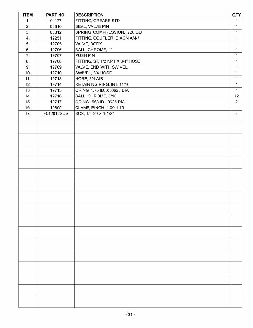
ITEM PART NO. DESCRIPTION QTY1. 01177 FITTING, GREASE STD 12. 03810 SEAL, VALVE PIN 13. 03812 SPRING, COMPRESSION, .720 OD 14. 12251 FITTING, COUPLER, DIXON AM-7 15. 19705 VALVE, BODY 16. 19706 BALL, CHROME, 1” 17. 19707 PUSH PIN 18. 19708 FITTING, ST, 1/2 NPT X 3/4” HOSE 19. 19709 VALVE, END WITH SWIVEL 110. 19710 SWIVEL, 3/4 HOSE 111. 19713 HOSE, 3/4 AIR 112. 19714 RETAINING RING, INT. 11/16 113. 19715 ORING, 1.75 ID, X .0625 DIA 114. 19716 BALL, CHROME, 3/16 1215. 19717 ORING, .563 ID, .0625 DIA 216. 19805 CLAMP, PINCH, 1.00-1.13 417. F042012SCS SCS, 1/4-20 X 1-1/2” 3
- 22 -
WARRANTY- AIRAMMER (AR56/AR57)
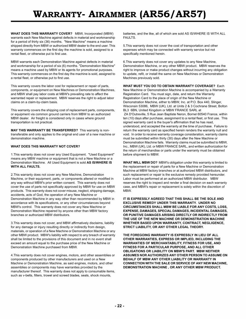
WHAT DOES THIS WARRANTY COVER? MBW, Incorporated (MBW) warrants each New Machine against defects in material and workmanship for a period of thirty six (36) months. "New Machine" means a machine shipped directly from MBW or authorized MBW dealer to the end user. This warranty commences on the first day the machine is sold, assigned to a rental fleet, or otherwise put to first use.
MBW warrants each Demonstration Machine against defects in material and workmanship for a period of six (6) months. "Demonstration Machine" means a machine used by MBW or its agents for promotional purposes. This warranty commences on the first day the machine is sold, assigned to a rental fleet, or otherwise put to first use.
This warranty covers the labor cost for replacement or repair of parts, components, or equipment on New Machines or Demonstration Machines, and MBW shall pay labor costs at MBW's prevailing rate to affect the warranted repair or replacement. MBW reserves the right to adjust labor claims on a claim-by-claim basis.
This warranty covers the shipping cost of replacement parts, components, or equipment via common ground carriers from MBW to an authorized MBW dealer. Air freight is considered only in cases where ground transportation is not practical.
MAY THIS WARRANTY BE TRANSFERRED? This warranty is non-transferable and only applies to the original end user of a new machine or demonstration machine.
WHAT DOES THIS WARRANTY NOT COVER?
1.This warranty does not cover any Used Equipment. "Used Equipment" means any MBW machine or equipment that is not a New Machine or a Demonstration Machine. All Used Equipment is sold AS IS/WHERE IS WITH ALL FAULTS.
2.This warranty does not cover any New Machine, Demonstration Machine, or their equipment, parts, or components altered or modified in any way without MBW's prior written consent. This warranty does not cover the use of parts not specifically approved by MBW for use on MBW products. This warranty does not cover misuse, neglect, shipping damage, accidents, acts of God, the operation of any New Machine or Demonstration Machine in any way other than recommended by MBW in accordance with its specifications, or any other circumstances beyond MBW's control. This warranty does not cover any New Machine or Demonstration Machine repaired by anyone other than MBW factory branches or authorized MBW distributors.
3.This warranty does not cover, and MBW affirmatively disclaims, liability for any damage or injury resulting directly or indirectly from design, materials, or operation of a New Machine or Demonstration Machine or any other MBW product. MBW's liability with respect to any breach of warranty shall be limited to the provisions of this document and in no event shall exceed an amount equal to the purchase price of the New Machine or Demonstration Machine purchased from MBW.
4.This warranty does not cover engines, motors, and other assemblies or components produced by other manufacturers and used on a New Machine or Demonstration Machine, as said engines, motors, and other assemblies or components may have warranties provided by the manufacturer thereof. This warranty does not apply to consumable items, such as v-belts, filters, trowel and screed blades, seals, shock mounts,
batteries, and the like, all of which are sold AS IS/WHERE IS WITH ALL FAULTS.
5.This warranty does not cover the cost of transportation and other expenses which may be connected with warranty service but not specifically mentioned herein. 6.This warranty does not cover any updates to any New Machine, Demonstration Machine, or any other MBW product. MBW reserves the right to improve or make product changes without incurring any obligation to update, refit, or install the same on New Machines or Demonstration Machines previously sold.
WHAT MUST YOU DO TO OBTAIN WARRANTY COVERAGE? Each New Machine or Demonstration Machine is accompanied by a Warranty Registration Card. You must sign, date, and return the Warranty Registration Card to the place of origin of the New Machine or Demonstration Machine, either to MBW, Inc. at P.O. Box 440, Slinger, Wisconsin 53086, MBW (UK), Ltd. at Units 2 & 3 Cochrane Street, Bolton BL3 6BN, United Kingdom or MBW FRANCE SARL at ZA D'Outreville, 5 Rue Jean Baptiste Neron, Bornel 60540 France, within ten (10) days after purchase, assignment to a rental fleet, or first use. This signed warranty card is the buyer's affirmation that he has read, understood, and accepted the warranty at the time of purchase. Failure to return the warranty card as specified herein renders the warranty null and void. In order to receive warranty coverage consideration, warranty claims must be submitted within thirty (30) days after the New Machine or Demonstration Machine fails. Warranty claims must be submitted to MBW, Inc., MBW (UK), Ltd. or MBW FRANCE SARL, and written authorization for the return of merchandise or parts under the warranty must be obtained before shipment to MBW.
WHAT WILL MBW DO? MBW's obligation under this warranty is limited to the replacement or repair of parts for a New Machine or Demonstration Machine at MBW factory branches or at authorized MBW distributors, and such replacement or repair is the exclusive remedy provided hereunder. Labor must be performed at an authorized MBW distributor. MBW reserves the right to inspect and render a final decision on each warranty case, and MBW's repair or replacement is solely within the discretion of MBW.
IT IS EXPRESSLY AGREED THAT THIS SHALL BE THE SOLE AND EXCLUSIVE REMEDY UNDER THIS WARRANTY. UNDER NO CIRCUMSTANCES SHALL MBW BE LIABLE FOR ANY COSTS, LOSS, EXPENSE, DAMAGES, SPECIAL DAMAGES, INCIDENTAL DAMAGES, OR PUNITIVE DAMAGES ARISING DIRECTLY OR INDIRECTLY FROM THE USE OF THE NEW MACHINE OR DEMONSTRATION MACHINE WHETHER BASED UPON WARRANTY, CONTRACT, NEGLIGENCE, STRICT LIABILITY, OR ANY OTHER LEGAL THEORY.
THE FOREGOING WARRANTY IS EXPRESSLY IN LIEU OF ALL OTHER WARRANTIES, EXPRESS OR IMPLIED, INCLUDING THE WARRANTIES OF MERCHANTABILITY, FITNESS FOR USE, AND FITNESS FOR A PARTICULAR PURPOSE, AND ALL OTHER OBLIGATIONS OR LIABILITY ON MBW'S PART. MBW NEITHER ASSUMES NOR AUTHORIZES ANY OTHER PERSON TO ASSUME ON BEHALF OF MBW ANY OTHER LIABILITY OR WARRANTY IN CONNECTION WITH THE SALE OR SERVICE OF ANY NEW MACHINE, DEMONSTRATION MACHINE , OR ANY OTHER MBW PRODUCT.