Pentair Berkeley Centrifugal Pump, CP, CB Series Manual
16
BE873 (08/01/20) ©2020. All Rights Reserved. CENTRIFUGAL PUMP CP, CB SERIES pentair.com INSTALLATION AND OPERATION MANUAL
Transcript of Pentair Berkeley Centrifugal Pump, CP, CB Series Manual

BE
873
(08
/01/
20) ©
2020
. All
Rig
hts
Res
erve
d.
CENTRIFUGAL PUMP CP, CB SERIES
pentair.com
INSTALLATION AND OPERATION MANUAL

2 BE873 (08-01-20)
TABLE OF CONTENTS
Safety Information ..................................................................................................................................................................................3
Installation .......................................................................................................................................................................................... 4-7
Operation .................................................................................................................................................................................................8
Parts List ............................................................................................................................................................................................9-13
Troubleshooting .................................................................................................................................................................................... 14
Warranty ................................................................................................................................................................................................ 15

3 BE873 (08-01-20)
IMPORTANT SAFETY INSTRUCTIONS
SAVE THESE INSTRUCTIONS: For optimal performance and operation, read these instructions carefully before installing your new pump. This manual provides valuable guidance and instructions that should be followed to perform installation, operation and maintenance procedures for this product. It should be kept near the installation for immediate reference. Record nameplate data from your new pump on the blank template located in “Maintenance” on Page 7 for future reference.
This is the safety alert symbol. When you see this symbol on your pump or in this manual, look for one of the following signal words and be alert to the potential for personal injury.
warns about hazards that will cause serious personal injury, death or major property damage if ignored.
warns about hazards that can cause serious personal injury, death or major property damage if ignored.
warns about hazards that will or can cause minor personal injury or property damage if ignored.
NOTICE indicates special instructions which are important but not related to hazards.
The hazards stated in this manual are not all-inclusive. To minimize the risk of hazard, it is strongly recommended that installation, operation and maintenance be performed by a qualified professional in accordance with local codes and standards for safe operation.
CALIFORNIA PROPOSITION 65 WARNING
This product and related accessories contain chemicals known to the State of California to cause cancer, birth defects or other reproductive harm.
ELECTRICAL SAFETY
Risk of electric shock. Can shock, burn or kill. All wiring should be done by a qualified electrician.
� Wire motor for correct voltage. See “Installation” section (refer to page 5) of this manual and motor nameplate.
� Ground motor before connecting to power supply.
� Follow wiring instructions in this manual when connecting motor to power lines.
� A complete power disconnect switch must be incorporated in the fixed wiring.
� Install, ground, wire and maintain your pump in compliance with all applicable national and local codes and ordinances. Consult your local building inspector for code information.
GENERAL SAFETY
Risk of explosion. The pump body may explode if used to boost pressure above the pressures noted on Page 3. Do not use this pump with inlet pressure greater than 70 psi (483 kPa)or less than 3 psi (20.7 kPa). If not already in the piping system, install a pressure relief valve in the pump discharge line capable of passing the full pump flow at maximum rated pressure. If local code requires installation of a pressure relief valve capable of handling the full pump flow at a pressure less than 100 psi (689 kPa), follow the code requirements.
Risk of fire or explosion. To avoid risk of fire and explosion, pump water only with this pump. Do not pump salt water, flammable liquids or chemicals. Do not use the pump near gas pilot lights or where chemical or gas fumes are present.Use of an electric pump with liquids other than water or in an atmosphere containing chemical or gas fumes may ignite those liquids or gases and cause injury or death due to an explosion and/or fire. Pump approved liquids only with this pump.
Risk of burns. If water is trapped in the pump during operation it may turn to steam. Trapped steam may cause an explosion resulting in injury or property damage. Never run the pump with the outlet closed or obstructed.
Risk of freezing. Do not allow pump, piping, or any other system component containing water to freeze. Freezing may damage system, leading to injury or flooding. Allowing pump or system components to freeze will void the warranty.
NOTICE only service agent or qualified person should replace power cord to avoid injury.
Periodically inspect pump and system components.
Wear safety glasses at all times when working on pumps.
Keep work area clean, uncluttered and properly lighted; store properly all unused tools and equipment.
ORDERING REPLACEMENT PARTS
Locate the Pentair Sta-Rite* nameplate on pump. This plate is normally on the pump case or bracket (seal plate). To ensure receipt of correct parts, provide all nameplate data when ordering. Catalog number is most important to reference. Write the nameplate information below, as nameplates can become worn or lost.
Model:
S.N. or Date:
Impeller Dia:
Catalog No:
SAFETY INFORMATION

4 BE873 (08-01-20)
Connection diagram for dual voltage, single-phase motors. Your dual-voltage motor’s terminal board (under the motor end cover) will match one of the diagrams below. Follow that diagram if necessary to convert motor to 115 Volt power.
Connect power supply wires to L1 and L2. For 3-phase motors, or if motor does not match these pictures, follow the connection diagram on the motor nameplate.
THE MOTOR IS SET FOR 230 VOLTS WHEN SHIPPED.To change the motor to use 115 volts:
1. Turn off power
2. Remove the back motor cover.
3. Use a screwdriver or 1/2” wrench and turn the voltage selector dial counterclockwise until 115 shows in the dial opening.
4. Reinstall the motor cover.
WARNING Hazardous voltage. Can shock, burn, or cause death. Disconnect power to motor before working on pump or motor. Ground motor before connecting to power supply.
WIRING
Ground motor before connecting to electrical power supply. Failure to ground motor can cause severe or fatal electrical shock hazard.
Do not ground to a gas supply line.
To avoid dangerous or fatal electrical shock, turn OFF power to motor before working on electrical connections.
Supply voltage must be within ±10% of nameplate voltage. Incorrect voltage can cause fire or damage motor and voids warranty. If in doubt consult a licensed electrician.
Use wire size specified in Wiring Chart (Page 3). If possible, connect pump to a separate branch circuit with no other appliances on it.
Wire motor according to diagram on motor nameplate. If nameplate diagram differs from diagrams above, follow nameplate diagram.
1. Install, ground, wire and maintain your pump in compliance with the National Electrical Code (NEC) in the U.S., or the Canadian Electrical Code (CEC), as applicable, and with all local codes and ordinances that apply. Consult your local building inspector for code information.
2. Provide a correctly fused disconnect switch for protection while working on motor. For switch requirements, consult your local building inspector for information about codes.
3. Disconnect power before servicing motor or pump. If the disconnect switch is out of sight of pump, lock it open and tag it to prevent unexpected power application.
4. Ground the pump permanently using a wire of the same size as that specified in wiring chart (Page 3). Make ground connection to green grounding terminal under motor canopy marked GRD. or .
5. Connect ground wire to a grounded lead in the service panel or to a metal underground water pipe or well casing at least 10 feet long. Do not connect to plastic pipe or insulated fittings.
6. Protect current carrying and grounding conductors from cuts, grease, heat, oil, and chemicals.
7. Connect current carrying conductors to terminals L1 and L2 under motor canopy. When replacing motor, check wiring diagram on motor nameplate against Figure 3. If the motor wiring diagram does not match either diagram in Figure 3, follow the diagram on the motor.
IMPORTANT: 115/230 Volt single phase models are shipped from factory with motor wired for 230 volts. If power supply is 115 volts, remove motor canopy and reconnect motor as shown in Figure 4. Do not try to run motor as received on 115 volt current.
8. Motor has automatic internal thermal overload protection. If motor has stopped for unknown reasons, thermal overload may restart it unexpectedly, which could cause injury or property damage. Disconnect power before servicing motor.
9. If this procedure or the wiring diagrams are confusing, consult a licensed electrician.
INSTALLATION
Figure 3: Changing the Voltage Setting
Figure 4: Motor Set for 115 Volt Operation
5 BE873 (08-01-20)
INSTALLATION
Rotatio
n
Support suction pipeas required, so thatpump does not takeweight of pipe
Support discharge pipeas required, so thatpump does not takeweight of pipe
As closeas possible
4 x "D"minimum
submergence
Foot Valve
Pipe diameter"D"
Straight run, as short aspossible but at least 6times pipe diameter ("D").Slope pipe down from pump to water
Short length of straight pipeafter reducer
Important:All connections mustbe air tight
Solid, levelbase
Tee andPriming Plug
Rotated Volute
StopValve
Union
Discharge to service
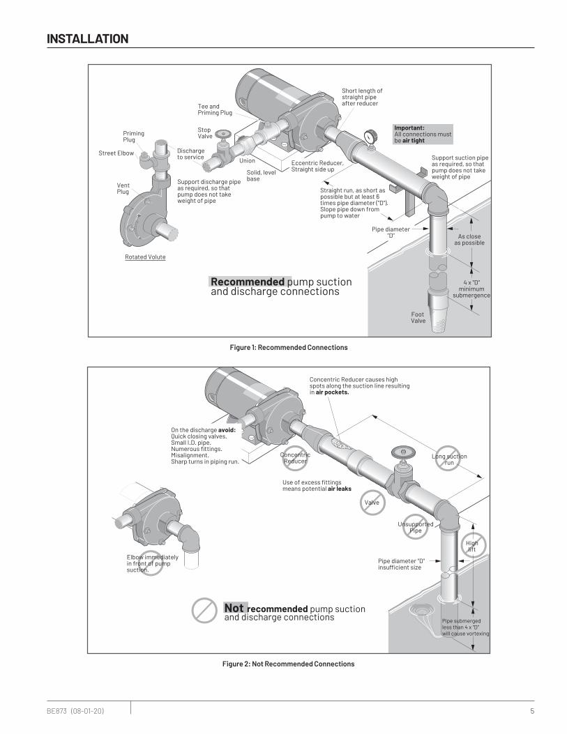
Recommended pump suctionand discharge connections
VentPlug
PrimingPlug
Street Elbow
Not recommended pump suctionand discharge connections
Elbow immediately in front of pump suction.
On the discharge avoid:Quick closing valves.Small I.D. pipe.Numerous �ttings.Misalignment.Sharp turns in piping run.
Highlift
Pipe diameter "D"insu�cient size
Pipe submergedless than 4 x "D"will cause vortexing
Long suctionrun
ConcentricReducer
Use of excess �ttingsmeans potential air leaks
Valve
UnsupportedPipe
Concentric Reducer causes highspots along the suction line resultingin air pockets.
1226 0894
Eccentric Reducer,Straight side up
Figure 2: Not Recommended Connections
Figure 1: Recommended Connections
Rotatio
n
Support suction pipeas required, so thatpump does not takeweight of pipe
Support discharge pipeas required, so thatpump does not takeweight of pipe
As closeas possible
4 x "D"minimum
submergence
Foot Valve
Pipe diameter"D"
Straight run, as short aspossible but at least 6times pipe diameter ("D").Slope pipe down from pump to water
Short length of straight pipeafter reducer
Important:All connections mustbe air tight
Solid, levelbase
Tee andPriming Plug
Rotated Volute
StopValve
Union
Discharge to service
Recommended pump suctionand discharge connections
VentPlug
PrimingPlug
Street Elbow
Not recommended pump suctionand discharge connections
Elbow immediately in front of pump suction.
On the discharge avoid:Quick closing valves.Small I.D. pipe.Numerous �ttings.Misalignment.Sharp turns in piping run.
Highlift
Pipe diameter "D"insu�cient size
Pipe submergedless than 4 x "D"will cause vortexing
Long suctionrun
ConcentricReducer
Use of excess �ttingsmeans potential air leaks
Valve
UnsupportedPipe
Concentric Reducer causes highspots along the suction line resultingin air pockets.
1226 0894
Eccentric Reducer,Straight side up

6 BE873 (08-01-20)
INSTALLATION
PIPING - GENERAL
Support both suction and discharge piping independently at a point near the pump to avoid putting a strain on the pump housing. Start all piping AT THE PUMP.
Increase pipe diameter at both the suction and discharge by one (1) standard pipe size (minimum) to obtain desired performance and flow rate. Refer to Table I when sizing pipe for your pumping system.
NOTICE: Do not use pipe with smaller diameter on the suction side of pump.
SUCTION PIPE
Increase pipe size from pump suction port as shown in Table I.
Figure 1 (Page 2) depicts a recommended run of pipe and fittings for the suction side of a centrifugal pump. Please refer to this illustration when choosing pipe and fittings for your suction connection.
IMPORTANT: All connections must be air tight!
Figure 2 (Page 2) depicts conditions that are NOT DESIRABLE on the suction side of a centrifugal pump and may cause problems in flow rate and priming. Please look this illustration over carefully before choosing pipe and fittings for your suction connection.
DISCHARGE PIPING
Increase pipe size from pump discharge port as shown in Table I. Figure 1 (Page 2) depicts a recommended run of pipe and fittings for the discharge. Install tee with priming plug as close to pump as possible. Figure 2 (Page 2) notes conditions that should be avoided. Please read over carefully before
making discharge connection.
PRIMING THE PUMP
A pump is primed when all air in the suction line and pump volute has been evacuated and replaced with water.
TO PRIME:
1. Close valve in discharge line.
2. Remove priming plug from tee and fill pump and suction line with water until water is flowing back out of tee
3. Replace priming plug.
4. Start pump and slowly open valve until desired water flow is achieved.
NOTICE: If water is not being pumped, turn off pump, close valve, and repeat steps 1 thru 4. If pump volute is rotated as shown in Figure 1 (Page 2), loosen vent plug when priming to evacuate air trapped inside volute. Tighten when volute is completely filled with water.
NOTICE: Do not run the pump dry. This will damage mechanical seal and void warranty.
CAUTION Burn hazard. Motor normally operates at high temperature and will be too hot to touch. It is protected from heat damage during operation by an automatic internal cutoff switch. Before handling pump or motor, stop motor and allow it to cool for 20 minutes.
Table I: Piping
PUMP PORT SIZE (NPT)
RECOMMENDED PIPE SIZE
Suction Discharge Suction Discharge
1-1/4 1 1-1/2 1-1/4
1-1/2 1-1/4 2 1-1/2
2 1-1/2 3 2
MODEL TYPEMedium Head – Noryl® Impellers
Medium Head – Brass Impellers
High Head – Noryl® Impellers
High Head – Brass Impellers
1/3 through 2-1/2 H.P.
115/230 Volt Single Phase
230 Volt Single Phase
230/460 Volt Three Phase

7 BE873 (08-01-20)
INSTALLATION
MOTOR HPMAX.LOAD AMPERES
BRANCH FUSE*
RATING AMPS
DIAMETER IN FEET FROM MOTOR TO METER
0' TO 50' 51' TO 100' 101' TO 200' 201' TO 300' 301' TO 400' 401' TO 500'
WIRE SIZE
SINGLE PHASE - 115 VOLT
1/3 9.4 15 14 14 12 10 8 8
1/2 9.4 15 14 14 12 10 8 8
3/4 12.2 20 12 12 10 8 6 4
1 14.8 20 12 12 8 6 6 4
1-1/2 19.2 30 10 10 8 6 4 2
2 24.0 30 12 10 6 6 4 4
SINGLE PHASE - 230 VOLT
1/3 4.7 15 14 14 14 12 12 10
1/2 4.7 15 14 14 14 12 12 10
3/4 6.1 15 14 14 14 14 12 10
1 7.4 15 14 14 14 12 12 10
1-1/2 9.6 15 14 14 14 12 10 10
2 12.0 15 14 14 12 12 10 8
2-1/2 12.0 15 14 14 12 12 10 8
THREE PHASE - 230 VOLT
1/2 2.3 15 14 14 14 14 14 14
3/4 3.1 15 14 14 14 14 14 14
1 3.6 15 14 14 14 14 14 14
1-1/2 4.7 15 14 14 14 14 14 14
2 6.8 15 14 14 14 14 14 12
2-1/2 8.5 15 14 14 14 14 14 12
THREE PHASE - 460 VOLT
1/2 1.15 15 14 14 14 14 14 14
3/4 1.55 15 14 14 14 14 14 14
1 1.8 15 14 14 14 14 14 14
1-1/2 2.35 15 14 14 14 14 14 14
2 3.4 15 14 14 14 14 14 14
2-1/2 4.25 15 14 14 14 14 14 14
*A Fusetron is recommended instead of a fuse in any motor circuit.
Table II - Recommended Fusing and Wiring Data - 60 cycle motors

8 BE873 (08-01-20)
OPERATION
Figure 5: Seal Install
PUMP SERVICEThis centrifugal pump requires little or no service other than reasonable care and periodic cleaning. Occasionally, however, a shaft seal (Key No. 4, Page 6) may become damaged and must be replaced. The procedure as outlined below will enable you to replace the seal.
NOTICE: These mechanical seals are supplied with either a rubber seat ring or a sealing O-Ring. They are completely interchangeable.
NOTICE: The highly polished and lapped faces of this seal are easily damaged. Read instructions and handle the seal with care.
Some models are equipped with an impeller screw, which has a left hand thread. Before unscrewing the impeller, remove the impeller screw.
REMOVAL OF OLD SEAL1. After unscrewing impeller (Key No. 5, Page 6), carefully
remove rotating part of seal by prying up on sealing washer, using two screwdrivers (see Figure 5A). Use care not to scratch motor shaft.
2. Remove seal plate (Key No. 3) from motor and place on flat surface, face down. Use a screwdriver to push ceramic seat out from seal cavity (see Figure 5B).
California Proposition 65 Warning
WARNING This product and related accessories contain chemicals known to the State of California to cause cancer, birth defects or other reproductive harm.
INSTALLATION OF FLOATING SEAT (FIGURE 5C)
1. Clean polished surface of floating (ceramic) seat with clean cloth.
2. Turn seal plate over so seal cavity is up; clean cavity thoroughly.
3. Lubricate outside rubber surface or O-Ring of ceramic seat with soapy water and press firmly into seal cavity with fingerpressure. If seat will not locate properly in this manner, place cardboard washer over polished face of seat and press into seal cavity using a 3/4” socket or 3/4” piece of standard pipe.
4. Dispose of cardboard washer. Be sure polished surface of seat is free of dirt and has not been damaged by insertion. Remove excess soapy water.
INSTALLATION OF ROTATING PART OF SEAL UNIT (FIGURE 5D)
1. Reinstall seal plate using extreme caution not to hit ceramic portion of seal on motor shaft.
2. Inspect shaft to make sure that it is clean.
3. Clean face of sealing washer with clean cloth.
4. Lubricate inside diameter and outer face of rubber drive ring (see Figure 5D) with soapy water and slide assembly on motor shaft (sealing face first) until rubber drive ring hits shaft shoulder.
5. Screw impeller on shaft until impeller hub hits shaft shoulder. This will automatically locate seal in place and move the sealing washer face uagainst the facing seat. Reinstall impeller screw (if used).
Seal Plate
Mechanical sealrotating half
Mechanical sealstationary half
A-Seal removal-rotating half B-Seal removal-stationary half C-Stationary half installation D-Rotating half installation
Turn over
Polishedsurface
Rubbersurface
Cardboardwasher
(supplied w/seal)
3/4" socket or pipe
Sealingface
Rubber drivering
Impeller
Shaftshoulder
5939 0109

9 BE873 (08-01-20)
PARTS LIST
Figure 7: Stud Configuration
111
2
3
104
7
5A
5
6
8
9
9A
12
12A
11
1227 0894
18A
2
3
104
7
5A
5
6
9
9A
12
12A
8A
1228 0894
Figure 6: Capscrew Configuration

10 BE873 (08-01-20)
PARTS LIST
KEYNO.
PARTDESCRIPTION
NO. USED
MOTOR AND HORSEPOWER
CP1MPS CP1-1/4XPS
1/3 HP
S39489
1/2 HPS39490S39491
3/4 HPS39492S39493
1 HPS39494S39495
1-1/2 HPS39496S39497
2 HPS39498S39499
1*Motor - 115/230V, 60 Cycle, Single Phase
1 J218-582APKG J218-582APKG J218-590PKG J218-596PKG J218-601PKG J218-883APKG
1*Motor - 230/460V, 60 Cycle, Three Phase
1 – AP100CL AP100DL AP100EL AP100FL AP100GL
†2 Water Slinger 1 17351-0009 17351-0009 17351-0009 17351-0009 17351-0009 17351-0009
3 Seal Plate 1 N3-8 N3-8 N3-8 N3-8 C3-52 C3-52
†4 Shaft Seal 1 U9-469 U9-469 U9-469 U9-469 U9-469 U9-469
5 Impeller - Single Phase 1 J105-42PHA J105-42PHA J105-42PJA J105-42P C105-114PNF C105-114PNG-A
5 Impeller - Three Phase 1 – J105-42PHA J105-42PJA J105-42PPA C105-114PNPA C105-114PNG-A
5AImpeller Screw - Single
Phase1 – – – – – C30-14SS
5AImpeller Screw - Three
Phase1 – C30-6SS C30-6SS C30-6SS C30-14SS C30-14SS
6Volute Assembly - w/
Wear Ring1 C101-122E C101-122E C101-122E C101-122 C201-123 C201-123
7 Wear Ring (only) (1) N23-7 N23-7 N23-7 N23-7 C23-19 C23-19
8Studs - 3/8 - 16 x
1-13/16” Lg.(4) – – – – U30-35SS U30-35SS
9 Pipe Plug - 1/4” NPT (1) – – – – U78-57DT U78-57DT
9A Drain Plug - 1/4” NPT (3) – – – – U78-941ZPV U78-941ZPV
8Capscrew - 3/8 - 16 x
1-1/2” Lg.2 U30-76ZP U30-76ZP U30-76ZP U30-76ZP – –
8ACapscrew - 3/8 - 16 x
1-1/4” Lg.2 U30-75ZP U30-75ZP U30-75ZP U30-75ZP – –
9A Drain Plug - 1/4” NPT 4 U78-941ZPV U78-941ZPV U78-941ZPV U78-941ZPV – –
†10 Gasket - Volute 1 N20-26N N20-26N N20-26N N20-26N C20-21N C20-21N
11 Nuts - 3/8 - 16 Hex 4 – – – – U36-38ZP U36-38ZP
12 Base 1 J104-9F J104-9F J104-9F J104-9F J104-9F J104-9F
12A Motor Pad 1 C35-5S C35-5S C35-5S C35-5S C35-5S C35-5S
* For repair or service to motors, always give the motor Model Number and any other data found on the Motor Model Plate.† Included in Seal & Gasket Kit.
Medium Head - Noryl® Impeller Repair Parts

11 BE873 (08-01-20)
PARTS LIST
KEYNO.
PARTDESCRIPTION
NO. USED
MOTOR AND HORSEPOWER
CB1MPS CB1-1/4XPS CB1-1/2XPS
1/2 HPS39503S39504
3/4 HPS39505S39506
1 HPS39507S39508
1-1/2 HPS39509S39510
2 HPS39511S39512
2-1/2 HPS39513S39514
1*Motor - 115/230V, 60 Cycle, Single Phase
1 J218-582APKG J218-590PKG J218-596PKG J218-601PKG J218-883APKG J218-628APKG
1*Motor - 230/460V, 60 Cycle, Three Phase
1 AP100CL AP100DL AP100EL AP100FL AP100GL AP100G5L
†2 Water Slinger 1 17351-0009 17351-0009 17351-0009 17351-0009 17351-0009 17351-0009
3 Seal Plate 1 N3-8 N3-8 N3-8 N3-52 C3-52 C3-52
†4 Shaft Seal 1 U9-469 U9-469 U9-469 U9-469 U9-469 U9-469
5 Impeller - Single Phase 1 J105-42MA J105-42LA J105-42NA J105-79B C105-73BA C105-80BA
5 Impeller - Three Phase 1 J105-42MA J105-42LA J105-42NA J105-79BA C105-73BA C105-80BA
5AImpeller Screw -
Single Phase1 – – – – C30-14SS C30-14SS
5AImpeller Screw -
Three Phase1 C30-6SS C30-6SS C30-6SS C30-14SS C30-14SS C30-14SS
6Volute Assembly -
Complete1 - - - C201-123 C201-123 C201-123B
6Volute Assembly - w/
Wear Ring1 C101-122E C101-122E C101-122 - - -
7 Wear Ring (only) (1) N23-7 N23-7 N23-7 N23-19 C23-19 C23-19
8Studs - 3/8 - 16 x
1-13/16” Lg.(4) – – – U30-35SS U30-35SS U30-35SS
9 Drain Plug - 1/4” NPT (4) – – – U78-941ZPV U78-941ZPV U78-941ZPV
8Capscrew - 3/8 - 16 x
1-1/2” Lg.2 U30-76ZP U30-76ZP U30-76ZP - – –
8ACapscrew - 3/8 - 16 x
1-1/4” Lg.2 U30-75ZP U30-75ZP U30-75ZP - – –
9 Drain Plug - 1/4” NPT 4 U78-941ZPV U78-941ZPV U78-941ZPV - – –
†10 Gasket - Volute 1 N20-26N N20-26N N20-26N N20-21N C20-21N C20-21N
11 Nuts - 3/8 - 16 Hex 4 – – – U36-38ZP U36-38ZP U36-38C
12 Base 1 J104-9F J104-9F J104-9F J104-9F J104-9F J104-9F
12A Motor Pad 1 C35-5S C35-5S C35-5S C35-5S C35-5S C35-5S
* For repair or service to motors, always give the motor Model Number and any other data found on the Motor Model Plate.† Included in Seal & Gasket Kit.
Medium Head - Brass Impeller Repair Parts

12 BE873 (08-01-20)
PARTS LIST
KEYNO.
PARTDESCRIPTION
NO. USED
MOTOR AND HORSEPOWER
CP1XPHS CP1-1/4TPHS CP1-1/2TPHS
1/2 HPS39516S39517
3/4 HPS39518S39519
1 HPS39520S39521
1-1/2 HPS39522S39523
2 HPS39524S39525
2-1/2 HPS39526S39527
1*Motor - 115/230V, 60 Cycle, Single Phase
1 J218-582APKG J218-590PKG J218-596PKG J218-601PKG J218-883APKG J218-628APKG
1*Motor - 230/460V, 60 Cycle, Three Phase
1 AP100CL AP100DL AP100EL AP100FL AP100GL AP100G5L
†2 Water Slinger 1 17351-0009 17351-0009 17351-0009 17351-0009 17351-0009 17351-0009
3 Seal Plate 1 C3-178 C3-178 C3-178 C3-178 C3-181 C3-181
†4 Shaft Seal 1 U9-469 U9-469 U9-469 U9-469 U9-469 U9-469
5 Impeller - Single Phase 1 C105-92PNX C105-92PMX C105-92PLX C105-92PBX C105-214PCA C105-214PA
5 Impeller - Three Phase 1 C105-92PNXA C105-92PMXA C105-92PLXA C105-92PBXA C105-214PCA C105-214PA
5AImpeller Screw -
Single Phase1 – – – – C30-14SS C30-14SS
5AImpeller Screw -
Three Phase1 C30-14SS C30-14SS C30-14SS C30-14SS C30-14SS C30-14SS
6Volute Assembly -
Complete1 C101-284A C101-284A C101-284A C101-284A C101-264 C101-264B
7 Wear Ring (only) (1) C23-27 C23-27 C23-27 C23-27 C23-19 C23-19
8 Capscrew - 3/8 - 16 x 1” 2 – – U30-74ZP U30-74ZP U30-74ZP U30-99SS
8ACapscrew - 3/8 - 16 x
1-1/4” (4) U78-75ZP U78-75ZP U78-75ZP U78-75ZP U78-75ZP U78-104ZP
9 Drain Plug - 1/4” NPT (3) U78-941ZPV U78-941ZPV U78-941ZPV U78-941ZPV U78-941ZPV U78-941ZPV
†10 Gasket - Volute 1 C20-121N C20-121N C20-121N C20-121N C20-122N C20-122N
12 Base 1 J104-9F J104-9F J104-9F J104-9F J104-9F J104-9F
12A Motor Pad 1 C35-5S C35-5S C35-5S C35-5S C35-5S C35-5S
* For repair or service to motors, always give the motor Model Number and any other data found on the Motor Model Plate.† Included in Seal & Gasket Kit.
High Head - Noryl® Impeller Repair Parts

13 BE873 (08-01-20)
PARTS LIST
KEYNO.
PARTDESCRIPTION
NO. USED
MOTOR AND HORSEPOWER
CB1XPHS CB1-1/4TPHS CB1-1/2TPHS
1/2 HPS39529S39530
3/4 HPS39531S39532
1 HPS39533S39534
1-1/2 HPS39535S39536
2 HPS39537S39538
2-1/2 HPS39539S39540
1*Motor - 115/230V, 60 Cycle, Single Phase
1 J218-582APKG J218-590PKG J218-596PKG J218-601PKG J218-883APKG J218-628APKG
1*Motor - 230/460V, 60 Cycle, Three Phase
1 AP100CL AP100DL AP100EL AP100FL AP100GL AP100G5L
†2 Water Slinger 1 17351-0009 17351-0009 17351-0009 17351-0009 17351-0009 17351-0009
3 Seal Plate 1 C3-178 C3-178 C3-178 C3-178 C3-181 C3-181
†4 Shaft Seal 1 U9-469 U9-469 U9-469 U9-469 U9-469 U9-469
5 Impeller - Single Phase 1 C5-256BA C5-256BAA C5-254BA C5-254BC C5-297BB C5-297B
5 Impeller - Three Phase 1 C5-256BA C5-256BAA C5-254BA C5-254BC C5-297BB C5-297B
5AImpeller Screw -
Single Phase1 – – – – C30-14SS C30-14SS
5AImpeller Screw -
Three Phase1 C30-14SS C30-14SS C30-14SS C30-14SS C30-14SS C30-14SS
6Volute Assembly -
Complete1 C101-284A C101-284A C101-284A C101-284A C101-264 C101-264B
7 Wear Ring (only) (1) C23-27 C23-27 C23-27 C23-27 C23-19 C23-19
8 Capscrew - 3/8 - 16 x 1” 2 – – - - U30-74ZP U30-74ZP
8ACapscrew - 3/8 - 16 x
1-1/4” 2 U30-75ZP U30-75ZP U30-75ZP U30-75ZP U30-75ZP U30-75ZP
8 Capscrew - 3/8 - 16 x 1” 2 U30-74ZP U30-74ZP U30-74ZP U30-74ZP U30-74ZP U30-74ZP
9 Drain Plug - 1/4” NPT (4) U78-941ZPV U78-941ZPV U78-941ZPV U78-941ZPV U78-941ZPV U78-941ZPV
†10 Gasket - Volute 1 C20-121N C20-121N C20-121N C20-121N C20-122N C20-122N
12 Base 1 J104-9F J104-9F J104-9F J104-9F J104-9F J104-9F
12A Motor Pad 1 C35-5S C35-5S C35-5S C35-5S C35-5S C35-5S
* For repair or service to motors, always give the motor Model Number and any other data found on the Motor Model Plate.† Included in Seal & Gasket Kit.
High Head - Brass Impeller Repair Parts

14 BE873 (08-01-20)
TROUBLESHOOTING
SYMPTOM POSSIBLE CAUSE CORRECTIVE ACTION
Failure to pump: Pump not properly primed.Make sure pump casing and suction line
are full of water. See priming instructions.
Reduced capacity and/or head:Air pockets or leaks in suction line. Check suction piping.
Clogged impeller. Remove and clean.
Air leaks in suction line. Check suction piping.
Pump loses prime:Excessive suction lift and operating too
near shut-off point.Move pump neaer to water level.
Water level drops while pumping, uncovering suction piping.
Check water supply. Add length of pipe to suction to keep submerged end under
water.
Mechanical troubles and noise: Bent shaft and/or damaged bearings.
Take motor to authorized motor repair shop.
Suction and/or discharge piping not properly supported and anchored.
See that all piping is supported to relieve strain on pump assembly.

15 BE873 (08-01-20)
WarrantyPentair BERKELEY® warrants to the original consumer purchaser (“Purchaser” or “You”) of the products listed in the table below, that they will be free from defects in material and workmanship for the Warranty Period shown in the table below.
Product Warranty Period
Water Systems:
Water Systems Products — jet pumps, small centrifugal pumps, submersible pumps and related accessories
whichever occurs first: 12 months from date of original installation, or 18 months from date of manufacture
Pentair Pro-Source® Composite Tanks 5 years from date of original installation
Pentair Pro-Source Steel Pressure Tanks 5 years from date of original installation
Pentair Pro-Source Epoxy-Lined Tanks 3 years from date of original installation
Agricultural/Commercial:
Centrifugals – close-coupled motor drive, frame mount, SAE mount, engine drive, VMS, SSCX, SSHM
12 months from date of original installation, or 24 months from date of manufacture
Submersible Turbines, 6” diameter and larger12 months from date of original installation, or 24 months from date of manufacture
Our warranty will not apply to any product that, in our sole judgement, has been subject to negligence, misapplication, improper installation, or improper maintenance. Examples that may result in denial of a warranty claim (this list is not all inclusive):• Damage caused by careless handling, improper repackaging, or shipping.• Damage due to misapplication, misuse, abuse, or failure to operate equipment as specified in the owner’s manual.• Damage caused by failure to install products as specified in the owner’s manual.• Damage due to unauthorized product modifications or failure to use Pentair original replacement parts.• Damage caused by negligence, or failure to properly maintain products as specified in the owner’s manual.• Damage caused by water freezing inside the product.• Accidental damage, fire, acts of God, or other circumstances outside the control of Pentair.
Without limiting the foregoing, operating a three phase motor with single phase power through a phase converter will void the warranty. Note also that three phase motors must be protected by three-leg, ambient compensated, extra-quick trip overload relays of the recommended size or the warranty is void.
All impeller diameters specified in the BEC2 pump sizing program have been tested and determined to not exceed the service factor of the specified motor. Oversized impeller diameters can be requested, however, use of an oversized impeller will void any warranty claims.
Your only remedy, and BERKELEY’s only duty under this warranty, is that BERKELEY repair or replace defective products (at BERKELEY’s choice). THE REMEDIES DESCRIBED HERE ARE YOUR SOLE AND EXCLUSIVE REMEDIES AND OUR ENTIRE LIABILITY FOR ANY BREACH OF THIS WARRANTY.
You must pay all labor and shipping charges associated with the warranty and must request warranty service through the installing dealer as soon as a problem is discovered. No request for service will be accepted if received after the Warranty Period has expired. This warranty is not transferable.
BERKELEY’S LIABILITY SHALL UNDER NO CIRCUMSTANCES EXCEED THE ACTUAL AMOUNT PAID BY YOU FOR THE PRODUCT AT ISSUE. BERKELEY SHALL NOT, UNDER ANY CIRCUMSTANCES, BE LIABLE FOR ANY CONSEQUENTIAL, INCIDENTAL, SPECIAL, PUNITIVE, OR CONTINGENT DAMAGES OR LOSSES WHATSOEVER, WHETHER DIRECT OR INDIRECT. THE FOREGOING WARRANTY IS EXCLUSIVE. EXCEPT FOR THE WARRANTY SET FORTH HEREIN, BERKELEY MAKES NO WARRANTY WHATSOEVER WITH RESPECT TO THE PRODUCTS, INCLUDING, BUT NOT TO ANY WARRANTIES OF MERCHANTABILITY OR WARRANTY OF FITNESS FOR A PARTICULAR PURPOSE, WHETHER EXPRESS OR IMPLIED BY LAW, COURSE OF DEALING, COURSE OF PERFORMANCE, USAGE OF TRADE OR OTHERWISE.
THE FOREGOING WARRANTIES SHALL NOT EXTEND BEYOND THE DURATION PROVIDED HEREIN. Some states do not allow the exclusion or limitation of incidental or consequential damages or limitations on the duration of an implied warranty, so the above limitations or exclusions may not apply to You. This warranty gives You specific legal rights and You may also have other rights which vary from state to state.
This Warranty is effective July 14, 2020 and replaces all undated warranties and warranties dated before July 14, 2020.
BERKELEY 293 Wright Street, Delavan, WI 53115
Phone: 888-237-5353 • Fax: 800-321-8793 • Pentair.com/BerkeleyIn Canada: 490 Pinebush Road, Unit 4, Cambridge, Ontario N1T 0A5
Phone: 800-363-7867 • Fax: 888-606-5484

Pentair trademarks and logos are owned by Pentair or its affiliates. Third party registered and unregistered trademarks and logos are the property of their respective owners. Because we are continuously improving our products and services, Pentair reserves the right to change specifications without prior notice. Pentair is an equal opportunity employer. Noryl® is a registered trademark of SABIC Global Technologies B.V.
BE873 (08-01-20) ©2020 Pentair. All Rights Reserved.
293 Wright Street | Delavan, WI 53115 | Ph: 888-237-5353 | Orders Fax: 800.321.8793 | pentair.com