PENNY SHAPED CRACK IN AN INFINITE...
22
Advanced Math. Models & Applications Vol.2, No.2, 2017, pp.117-138 117 PENNY SHAPED CRACK IN AN INFINITE TRANSVERSELY ISOTROPIC PIEZOELECTRIC LAYER UNDER SYMMETRICALLY APPLIED LINE LOAD Rajesh Patra 1 , Sakti Pada Barik 2 , P.K.Chaudhuri 3 1 Department of Mathematics, Hooghly Engineering & Technology College, Vivekananda Road, Hooghly-712103, India 2 Department of Mathematics, Gobardanga Hindu College, 24-Parganas (N), Pin-743273, India 3 Retired Professor, Department of Applied Mathematics, University of Calcutta, 92, A.P.C. Road,Kolkata-700009, India Abstract. The present paper is concerned with the study of an internal penny shaped crack problem in an infinite transversely isotropic piezoelectric layer. The crack is supposed to be opened by an internal uniform pressure 0 p along its faces. The layer surfaces are assumed to be acted upon by a uniformly applied line load of magnitude P acting along the circumference of a circle of radius ) ( b a .The applied load may be tensile or compressive in nature. Furthermore, it is assumed that the line joining the centers of the two line load circles passes through the center of the penny shaped crack and is perpendicular to the plane of the crack. Due to the assumed symmetries in material properties as well as the symmetry in applied loadings the present problem can easily be modeled as a two dimensional problem. Using Hankel transform technique the solution of the problem has been reduced to the solution of two singular integral equations. The integral equations are solved numerically. The stress-intensity factor and the crack opening displacements are determined and the effects of piezoelectricity and anisotropy on them in both the cases are shown graphically. Keywords: piezoelectric medium, transversely isotropic medium, integral transform, Fredholm integral equation, stress-intensity factor. AMS Subject Classification: 97M10. Corresponding Author: Dr. Sakti Pada Barik, Department of Mathematics, Gobardanga Hindu College,24-Parganas (N),Pin-743273, India, e-mail: [email protected] Manuscript received: 12 February2017 1. Introduction In course of the study of various properties of solid materials, the discovery of the piezoelectric effect has attracted the special attention of the scientists. Piezoelectric effect was discovered by Jacques and Pierre Curie in 1880. It was found that during deformation of some crystals there was generation of electric charges on their surfaces. The reverse effect was observed in 1881 in which application of electric field on the boundary of certain crystals generates stress and strain in those crystals. These materials turn out to be very useful for their very special and unusual properties to produce electrical energy through use of mechanical loadings. Piezoelectric
Transcript of PENNY SHAPED CRACK IN AN INFINITE...
Advanced Math. Models & Applications
Vol.2, No.2, 2017, pp.117-138
117
PENNY SHAPED CRACK IN AN INFINITE TRANSVERSELY
ISOTROPIC PIEZOELECTRIC LAYER UNDER
SYMMETRICALLY APPLIED LINE LOAD
Rajesh Patra1, Sakti Pada Barik
2, P.K.Chaudhuri
3
1Department of Mathematics, Hooghly Engineering & Technology College,
Vivekananda Road, Hooghly-712103, India 2Department of Mathematics, Gobardanga Hindu College, 24-Parganas (N),
Pin-743273, India 3 Retired Professor, Department of Applied Mathematics, University of Calcutta,
92, A.P.C. Road,Kolkata-700009, India
Abstract. The present paper is concerned with the study of an internal penny shaped crack
problem in an infinite transversely isotropic piezoelectric layer. The crack is supposed to be
opened by an internal uniform pressure 0p along its faces. The layer surfaces are assumed to
be acted upon by a uniformly applied line load of magnitude P acting along the
circumference of a circle of radius )( ba .The applied load may be tensile or compressive
in nature. Furthermore, it is assumed that the line joining the centers of the two line load
circles passes through the center of the penny shaped crack and is perpendicular to the plane
of the crack. Due to the assumed symmetries in material properties as well as the symmetry
in applied loadings the present problem can easily be modeled as a two dimensional
problem. Using Hankel transform technique the solution of the problem has been reduced to
the solution of two singular integral equations. The integral equations are solved numerically.
The stress-intensity factor and the crack opening displacements are determined and the
effects of piezoelectricity and anisotropy on them in both the cases are shown graphically.
Keywords: piezoelectric medium, transversely isotropic medium, integral transform, Fredholm
integral equation, stress-intensity factor.
AMS Subject Classification: 97M10.
Corresponding Author: Dr. Sakti Pada Barik, Department of Mathematics, Gobardanga Hindu
College,24-Parganas (N),Pin-743273, India, e-mail: [email protected] Manuscript received: 12 February2017
1. Introduction
In course of the study of various properties of solid materials, the
discovery of the piezoelectric effect has attracted the special attention of the
scientists. Piezoelectric effect was discovered by Jacques and Pierre Curie in
1880. It was found that during deformation of some crystals there was
generation of electric charges on their surfaces. The reverse effect was
observed in 1881 in which application of electric field on the boundary of
certain crystals generates stress and strain in those crystals. These materials
turn out to be very useful for their very special and unusual properties to
produce electrical energy through use of mechanical loadings. Piezoelectric
ADVANCED MATH. MODELS & APPLICATIONS, V.2, N.2, 2017
118
materials, in particular, piezoelectric ceramics, have been widely used for
applications in various fields such as sensors, filters, ultrasonic generators,
actuators, laser, supersonics, microwave, navigation and biology. Piezoelectric
composite materials are also in use in hydrophone application and transducers
for medical imaging. Considering the huge applicability of these materials in
various fields, solid mechanics problems are being studied in solids with
piezoelectric properties.
The determination of the state of stress in medium under applied load
has been the subject of study in literature for many years. The study needs
special attention and care when the elastic body develops a crack in it.
Presence of a crack in a structure not only affects the stress distribution in it
but also drastically reduces the life span of the structure. Presence of a crack
in a solid also significantly changes its response to the applied load. Stress
distributions in the solid with a crack are studied in two regions: the region in
the neighborhood of crack, called the near field region and the region far away
from the crack, called the far field region. Study of stress distribution in the
near field region is very important because of the generation of stress of very
high magnitude at the crack boundary leading to possible spread of crack.
Stress intensity factor, crack energy etc. are some of the measurable quantities
used for checking possible crack expansion. For a solid with a crack in it
loaded mechanically or thermally [2, 4, 5, 8, 10, 11, 12, 17, 18] determination
of stress intensity factor (SIF) becomes a very important task in fracture
mechanics. SIF needs to be understood if we are to design fracture tolerant
materials used in bridges, buildings, aircraft, or even bells. Polishing just
won’t do if we detect crack. Crack problems in piezoelectric medium have
been studied in literature following classical theory. A comprehensive list of
work on crack problems in piezoelectric media done by earlier investigators
can be found in [1, 3, 6, 7, 13, 16, 19, 20, 21, 23, 24].
The present investigation aims at investigating an internal penny shaped
crack problem in an infinite transversely isotropic piezoelectric layer. The
crack faces are parallel to the layer surfaces and the layer surfaces are under
the action of compressive or tensile line loads applied along the circumference
of circle such that the line joining the centers of these circles is perpendicular
to the plane of the crack and passing to its centre. Hankel transform of
different orders are applied on the governing equations and boundary
conditions. Thereafter, using operator theory a general solution in terms of
three potential functions has been derived. These functions satisfy differential
equations of the second order and are quasi-harmonic functions. Making use
of these fundamental solutions, the crack problem in the aforesaid case is
investigated. The solution of the problem has been reduced to the solution of
Fredholm type integral equation of second kind which requires numerical
treatment. Numerical solution is obtained through the process of discretization
of the integrals, and based on the available parameter values, evaluation of
stresses, SIF etc are obtained. Finally, a discussion is made on the obtained
results presented graphically.
RAJESH PATRA et al.: PENNY SHAPED CRACK IN AN INFINITE …
119
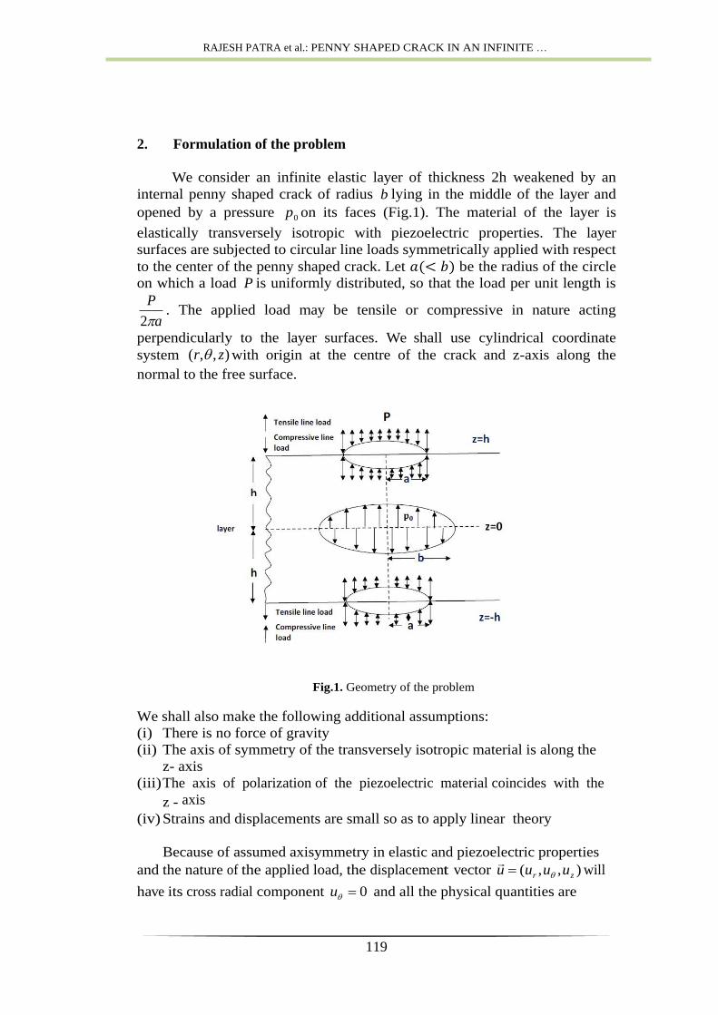
2. Formulation of the problem
We consider an infinite elastic layer of thickness 2h weakened by an
internal penny shaped crack of radius b lying in the middle of the layer and
opened by a pressure 0p on its faces (Fig.1). The material of the layer is
elastically transversely isotropic with piezoelectric properties. The layer
surfaces are subjected to circular line loads symmetrically applied with respect
to the center of the penny shaped crack. Let be the radius of the circle
on which a load P is uniformly distributed, so that the load per unit length is
a
P
2. The applied load may be tensile or compressive in nature acting
perpendicularly to the layer surfaces. We shall use cylindrical coordinate
system ),,( zr with origin at the centre of the crack and z-axis along the
normal to the free surface.
Fig.1. Geometry of the problem
We shall also make the following additional assumptions:
(i) There is no force of gravity
(ii) The axis of symmetry of the transversely isotropic material is along the
z- axis
(iii) The axis of polarization of the piezoelectric material coincides with the
z - axis
(iv) Strains and displacements are small so as to apply linear theory
Because of assumed axisymmetry in elastic and piezoelectric properties
and the nature of the applied load, the displacement vector ),,( zr uuuu
will
have its cross radial component 0u and all the physical quantities are
ADVANCED MATH. MODELS & APPLICATIONS, V.2, N.2, 2017
120
independent of . The problem may thus be considered as a two dimensional
one in the zr plane with r0 and .hzh
The mathematical formulation of the problem consists of
(A) Equilibrium equations:
(1)
where
,
and
(B) The boundary conditions:
(2)
(3)
(4)
(5)
(6)
(7)
(8)
(9)
(10)
The parameters appearing in (1) are the elastic coefficients whereas and
are piezoelectric and dielectric constants respectively of the material. In
addition to the boundary conditions, the displacement components and the
potential function should satisfy the regularity condition
as . Here is an unknown function and is the Dirac
delta function. In equation (4) positive sign indicates tensile force while
negative sign corresponds to compressive force.
2. Method of solution
Solution of the partial differential equations (1) requires application of
Hankel transform of different order. We shall follow the method adopted by
[7] in our solution process. For clarity in our method of solution it would be
better if briefly outline the first part of the method adopted by [7] here. We
shall use Hankel transform with respect to variable r to be denoted by ˆ, of
RAJESH PATRA et al.: PENNY SHAPED CRACK IN AN INFINITE …
121
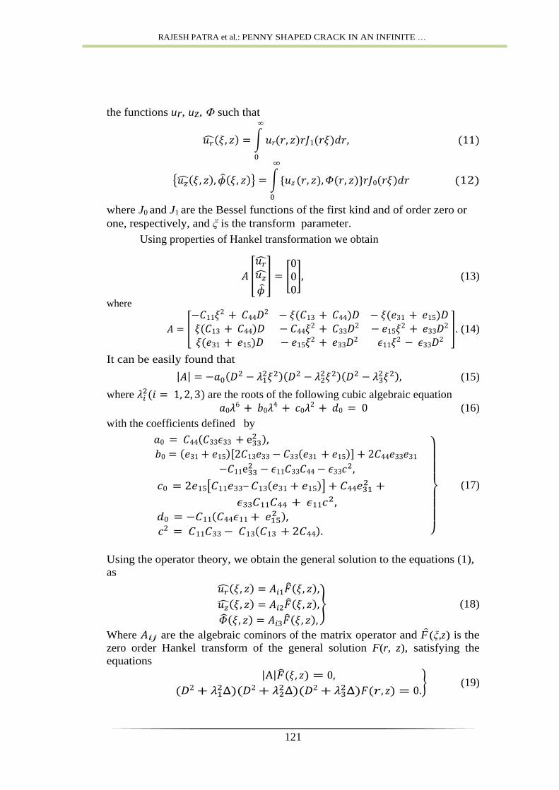
the functions ur, uz, Φ such that
where J0 and J1 are the Bessel functions of the first kind and of order zero or
one, respectively, and ξ is the transform parameter.
Using properties of Hankel transformation we obtain
(13)
where
. (14)
It can be easily found that
(15)
where are the roots of the following cubic algebraic equation
(16)
with the coefficients defined by
–
(17)
Using the operator theory, we obtain the general solution to the equations (1),
as
(18)
Where are the algebraic cominors of the matrix operator and F (ξ,z) is the
zero order Hankel transform of the general solution F(r, z), satisfying the
equations
(19)
ADVANCED MATH. MODELS & APPLICATIONS, V.2, N.2, 2017
122
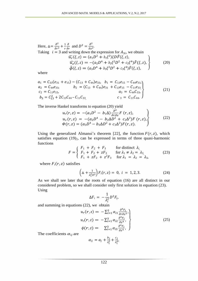
Here,
and
.
Taking and writing down the expression for , we obtain
(20)
where
–
(21)
The inverse Hankel transforms to equation (20) yield
(22)
Using the generalized Almansi’s theorem [22], the function which
satisfies equation (19)2, can be expressed in terms of three quasi-harmonic
functions
(23)
where satisfies
(24)
As we shall see later that the roots of equation (16) are all distinct in our
considered problem, so we shall consider only first solution in equation (23).
Using
and summing in equations (22), we obtain
(25)
The coefficients are
,
RAJESH PATRA et al.: PENNY SHAPED CRACK IN AN INFINITE …
123
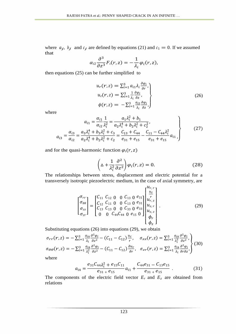
where and are defined by equations (21) and . If we assumed
that
then equations (25) can be further simplified to
(26)
where
and for the quasi-harmonic function
The relationships between stress, displacement and electric potential for a
transversely isotropic piezoelectric medium, in the case of axial symmetry, are
. (29)
Substituting equations (26) into equations (29), we obtain
(30)
where
The components of the electric field vector and are obtained from
relations
ADVANCED MATH. MODELS & APPLICATIONS, V.2, N.2, 2017
124
The electric displacements are defined by equations
. (33)
In terms of
where
It can be easily verified that:
Gauss’ law [16]
and equilibrium equations for stresses [14]
are satisfied.
In the vacuum, constitutive equations (33) and governing equations
(36) become
(38)
where is the electric permittivity of the vacuum.
For axially symmetric problems, the general solution of the differential
equation (28) may be written as
RAJESH PATRA et al.: PENNY SHAPED CRACK IN AN INFINITE …
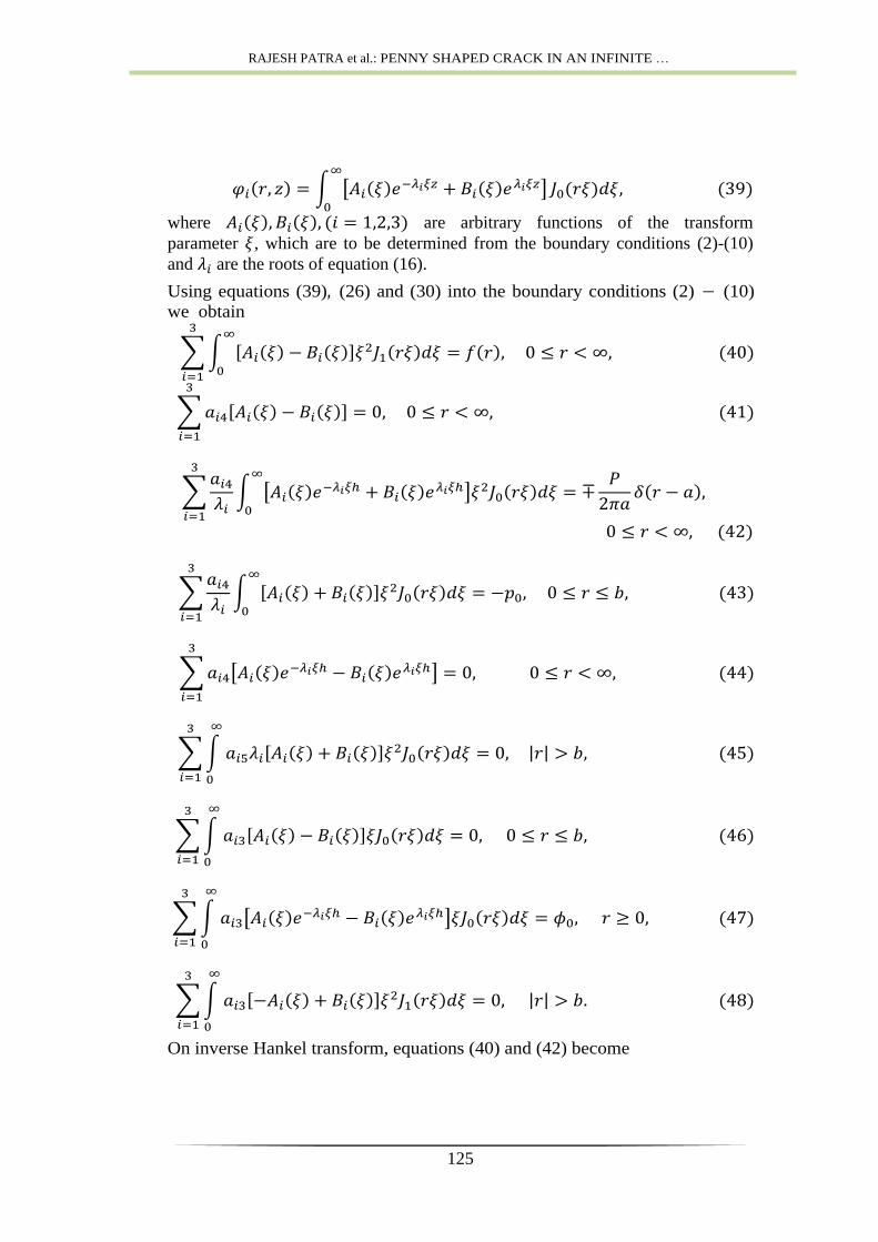
125
where are arbitrary functions of the transform
parameter , which are to be determined from the boundary conditions (2)-(10)
and are the roots of equation (16).
Using equations (39), (26) and (30) into the boundary conditions (2) − (10)
we obtain
On inverse Hankel transform, equations (40) and (42) become
ADVANCED MATH. MODELS & APPLICATIONS, V.2, N.2, 2017
126
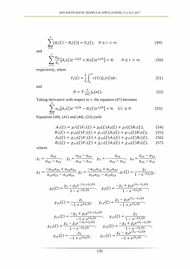
and
respectively, where
and
(52)
Taking derivative with respect to the equation (47) becomes
Equations (49), (41) and (44), (53) yield
(54)
(55)
(56)
(57)
where
RAJESH PATRA et al.: PENNY SHAPED CRACK IN AN INFINITE …
127
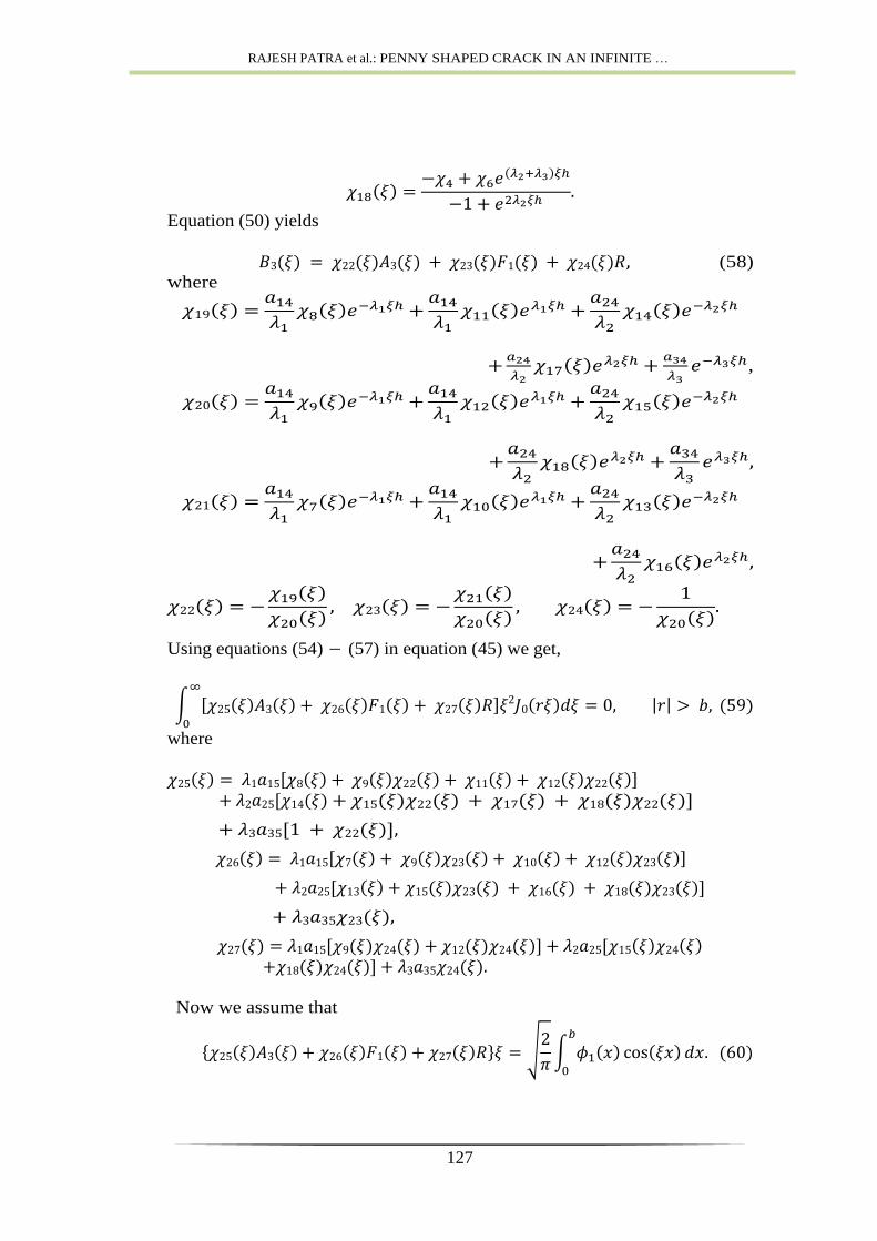
Equation (50) yields
(58)
where
,
Using equations (54) − (57) in equation (45) we get,
where
Now we assume that
ADVANCED MATH. MODELS & APPLICATIONS, V.2, N.2, 2017
128
Then equation (59) is automatically satisfied. Use of equations (54) − (57)
into (48) leads
where
Now we assume that
Then equation (61) is automatically satisfied. Solving equations (60) and
(62) we get
and
where
RAJESH PATRA et al.: PENNY SHAPED CRACK IN AN INFINITE …
129
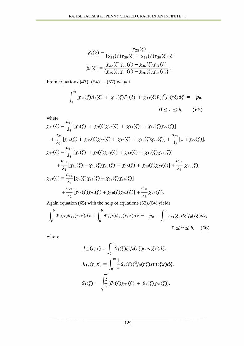
From equations (43), (54) − (57) we get
where
Again equation (65) with the help of equations (63),(64) yields
(66)
where
ADVANCED MATH. MODELS & APPLICATIONS, V.2, N.2, 2017
130
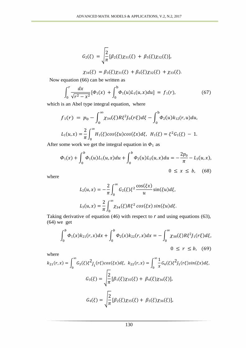
Now equation (66) can be written as
which is an Abel type integral equation, where
After some work we get the integral equation in as
where
Taking derivative of equation (46) with respect to r and using equations (63), (64) we get
where
RAJESH PATRA et al.: PENNY SHAPED CRACK IN AN INFINITE …
131
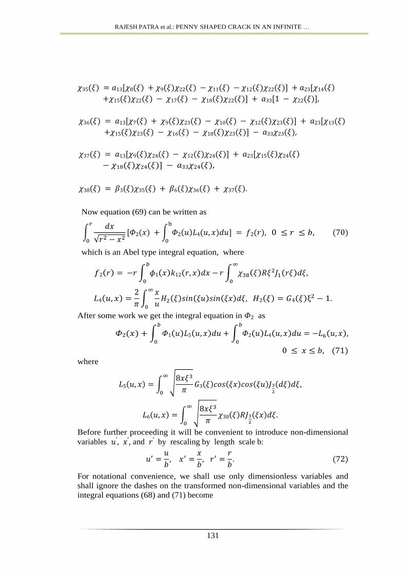
Now equation (69) can be written as
which is an Abel type integral equation, where
After some work we get the integral equation in as
where
Before further proceeding it will be convenient to introduce non-dimensional
variables , and by rescaling by length scale b:
For notational convenience, we shall use only dimensionless variables and
shall ignore the dashes on the transformed non-dimensional variables and the
integral equations (68) and (71) become
ADVANCED MATH. MODELS & APPLICATIONS, V.2, N.2, 2017
132
(73)
(74)
where is the load ratio defined as:
These equations determine functions and .
3. Determination of stress intensity factor
Presence of a crack in a solid significantly affects the stress distribution
compared to that when there is no crack. While the stress distribution in a
solid with a crack in the region far away from the crack is not much disturbed,
the stresses in the neighborhood of the crack tip assumes a very high
magnitude. In order to predict whether the crack has a tendency to expand
further, the stress intensity factor (SIF), a quantity of physical interest, has
been defined in fracture mechanics. The load at which failure occurs is
referred to as the fracture strength. The stress intensity factor is defined as
where
Use of the equations (66) and (5) and after some manipulation, the expression
for is obtained as
where can be found out from the numerical solutions of the equations
(73) and (74). Following the method as in [9] we obtain the crack surface
displacement in the form
Taking the inversion of Hankel transform of equation (49) and using the
equation (64) into the equation (76), we can express the dimensionless normal
displacement as
which can be obtained numerically, using Simpson’s
integration formula
RAJESH PATRA et al.: PENNY SHAPED CRACK IN AN INFINITE …
133
and the appropriate interpolation formula.
5. Numerical results and discussions
The present study shows how the presence of a crack in an anisotropic
piezoelectric layer under applied line load affects stress distribution and crack
surface displacement values and how the SIF is influenced by the anisotropic
and piezoelectric character of the medium and also by the position of the
applied load. Since these effects are not easily visible from our complex
theoretical expressions, we have numerically solved the relevant equations
based on the elastic and piezoelectric material parameter values for some
specific materials. In our numerical computation we have considered the
piezoelectric materials PZT-4 and PZT-5. The parameter values for PZT-4
[15] are
and those of PZT-5 [7] are
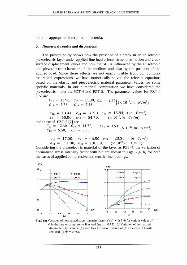
Considering the piezoelectric material of the layer as PZT-4, the variation of
normalized stress intensity factor with b/h are shown in Figs. 2(a, b) for both
the cases of applied compressive and tensile line loadings.
Fig.2 (a) Variation of normalized stress-intensity factor with for various values of
in the case of compressive line load . (b)Variation of normalized
stress-intensity factor with for various values of in the case of tensile
line load .
ADVANCED MATH. MODELS & APPLICATIONS, V.2, N.2, 2017
134
b
It is observed from Fig.2(a) that for compressive line loading the normalized
stress-intensity factor decreases with the increase of the load ratio and
the increase of is quite significant for smaller values of . It is also
observed from Fig.2(a) that the load ratio does not have much effect on the
stress intensity factor for sufficiently small values of crack radius. Fig 2(b)
represents the variations of with crack length under tensile nature of line
loading. Contrary to the previous case it is observed that increases with
.For small crack radius, the behavior of is similar to the case of
compressive line loading.
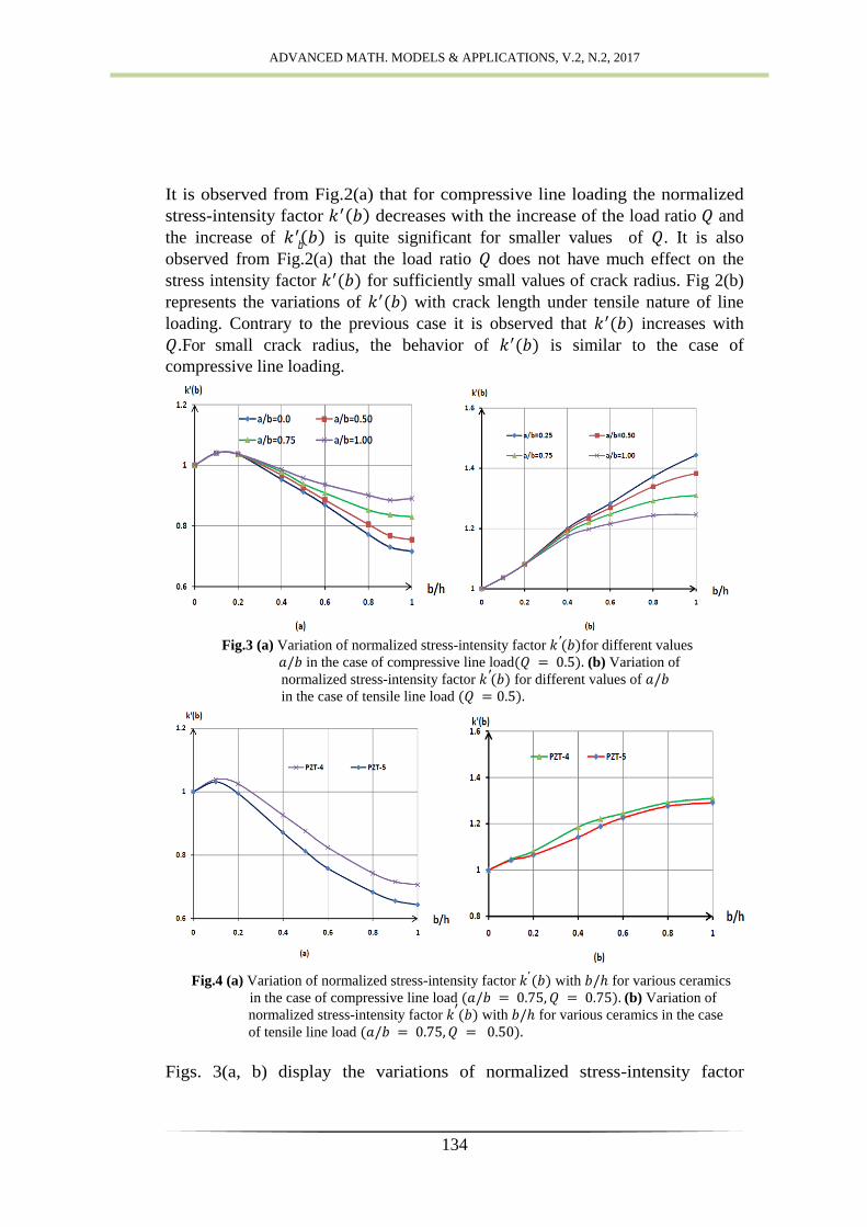
Fig.3 (a) Variation of normalized stress-intensity factor for different values
in the case of compressive line load (b) Variation of
normalized stress-intensity factor for different values of
in the case of tensile line load
Fig.4 (a) Variation of normalized stress-intensity factor with for various ceramics
in the case of compressive line load (b) Variation of
normalized stress-intensity factor with for various ceramics in the case
of tensile line load
Figs. 3(a, b) display the variations of normalized stress-intensity factor
RAJESH PATRA et al.: PENNY SHAPED CRACK IN AN INFINITE …
135
for different line loading radius. It is noted that in the case of compressive
line loading, increases with increasing
, but it decreases in the case of
tensile line loading. In Figs. 4(a, b) normalized stress intensity factor experiences
the effect of piezoelectric behavior under applied compressive and tensile line
loadings corresponding to load ratio values and
respectively. The normalized SIF are similar in behavior in respect of variation of
crack radius but PZT-5 showing relatively smaller values.
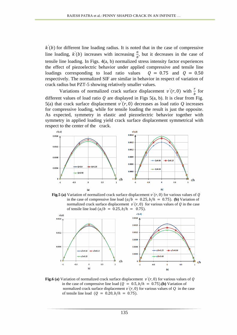
Variations of normalized crack surface displacement with
for
different values of load ratio are displayed in Figs 5(a, b). It is clear from Fig.
5(a) that crack surface displacement decreases as load ratio Q increases
for compressive loading, while for tensile loading the result is just the opposite.
As expected, symmetry in elastic and piezoelectric behavior together with
symmetry in applied loading yield crack surface displacement symmetrical with
respect to the center of the crack.
Fig.5 (a) Variation of normalized crack surface displacement for various values of
in the case of compressive line load (b) Variation of
normalized crack surface displacement for various values of in the case
of tensile line load
Fig.6 (a) Variation of normalized crack surface displacement for various values of
in the case of compressive line load (b) Variation of
normalized crack surface displacement for various values of Q in the case
of tensile line load

ADVANCED MATH. MODELS & APPLICATIONS, V.2, N.2, 2017
136
Figs.6(a, b) illustrate the role of the radius of the applied loading circle on the
normalized crack surface displacement for particular values of
and
load ratio for compressive loading and for tensile loading.
It is observed in Fig 6(a) that for compressive loading the normalized
crack surface displacement increases with the increased values of
but behavior
is just the opposite (Fig. 6(b)) for tensile loading. The effects of piezoelectric
behavior on normalized crack surface displacement are shown in Figs.
7(a, b) taking
and load ratio and for
compressive and tensile loadings respectively. As expected it is observed from
Figs. 5-7, that the normalized crack surface displacement assumes its
maximum magnitude near the center of the crack.
Fig.7(a) Comparison of normalized crack surface displacement for various ceramics in the
case of compressive line load
(b) Comparison of
normalized crack surface displacement for various ceramics in the case of tensile
line load
Fig.8 (a) Variation of electric displacement with for different values of for
compressive line load (b) Variation of electric
displacement with r for different values of for tensile line load
RAJESH PATRA et al.: PENNY SHAPED CRACK IN AN INFINITE …
137
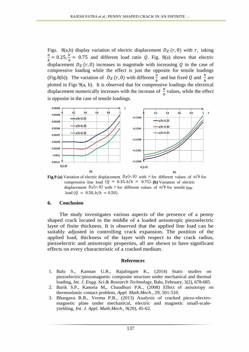
Figs. 8(a,b) display variation of electric displacement with taking
and different load ratio Fig. 8(a) shows that electric
displacement increases in magnitude with increasing in the case of
compressive loading while the effect is just the opposite for tensile loadings
(Fig.8(b)). The variation of with different
and but fixed and
are
plotted in Figs 9(a, b). It is observed that for compressive loadings the electrical
displacement numerically increases with the increase of
values, while the effect
is opposite in the case of tensile loadings.
Fig.9 (a) Variation of electric displacement with for different values of for
compressive line load (b) Variation of electric
displacement with for different values of for tensile line
load .
6. Conclusion
The study investigates various aspects of the presence of a penny
shaped crack located in the middle of a loaded anisotropic piezoelectric
layer of finite thickness. It is observed that the applied line load can be
suitably adjusted in controlling crack expansion. The position of the
applied load, thickness of the layer with respect to the crack radius,
piezoelectric and anisotropic properties, all are shown to have significant
effects on every characteristic of a cracked medium.
References
1. Balu S., Kannan G.R., Rajalingam K., (2014) Static studies on
piezoelectric/piezomagnetic composite structure under mechanical and thermal
loading, Int. J. Engg. Sci.& Research Technology, Balu, February, 3(2), 678-685.
2. Barik S.P., Kanoria M,, Chaudhuri P.K., (2008) Effect of anisotropy on
thermoelastic contact problem, Appl. Math.Mech., 29, 501-510.
3. Bhargava R.R., Verma P.R., (2013) Analysis of cracked piezo-electro-
magnetic plate under mechanical, electric and magnetic small-scale-
yielding, Int. J. Appl. Math.Mech., 9(20), 45-62.
ADVANCED MATH. MODELS & APPLICATIONS, V.2, N.2, 2017
138
4. Birinci A., Birinci F., Cakiroglu F.L., Erdol R., (2010) An internal crack
problem for an infinite elastic layer, Arch. Appl. Mech., 80, 997-1005.
5. Chen W., Ding H., Hou P., (2001) Exact solution of an external circular
crack in a piezoelectric solid subjected to shear loading, J. Zhejiang University
(Science), 2(1), 9-14.
6. Dai M., Schiavone P., Gao C., (2016) An anisotropic piezoelectric half-plane
containing an elliptical hole or crack subjected to uniform in-plane
electromechanical loading, J. Mech. Materials and Struc., 11(4),
DOI:10.2140/jomms.2016.11.433,433-448.
7. Dyka E., Rogowski B., (2005) On the contact problem for a smooth punch in
piezoelectroelasticity, J. Theo. Appl. Mech. Warsaw, 43, 745-761.
8. Fabrikant V.I., (1996) Interaction of an arbitrary force with a flexible punch
or with an external circular crack, Int.J.Engg.Sci., 34, 1753-1765.
9. Gupta G.D., Erdogan F., (1974) The problem of edge cracks in an infinite strip,
J. Appl. Mech., 41, 1001-1006.
10. Kalamkarov A.L., Pedro P.M.C.L., Savi M.A., Basu A., (2015) Analysis of
Magneto-Piezoelastic Anisotropic Materials, Metals, 5,
doi:10.3390/met5020863,863-880.
11. Karapetian E., Sevostianov I., Kachanov M., (2000) Penny-shaped and half-
plane cracks in a transversely isotropic piezoelectric solid under arbitrary
loading, Arch. Appl. Mech., Springer-Verlag, 70, 201-229.
12. Ma C.C., Luo J.J., (1996) Plane solution of interface cracks in anisotropic
dissimilar media, J. Engg. Mech., 122, 30-38.
13. Mishuris G.,Piccolroaz A.,Vellender A., (2014) Boundary integral formulation
for cracks at imperfect interfaces, Q. J. Mech. Appl. Math.,67,363-387.
14. Nowacki W., Teoria Sprezystosci, PWN, Warszawa, 1973.
15. Park S.B., Sun C.T., (1995) Fracture criteria for piezoelectric ceramics, J. Am.
Ceram. Soc., 78, 1475-1480.
16. Parton V.Z., Kudryatvsev B.A., Electromagnetoelasticity, Gordon and
Breach, New York, 1988.
17. Patra R., Barik S.P., Kundu M., Chaudhuri P.K., (2014) Plane elastostatic
solution in an infinite functionally graded layer weakened by a crack lying in
the middle of the layer, Int. J. Comp. Math, Article ID 358617.
18. Patra R., Barik S.P., Chaudhuri P.K., (2015) An internal crack problem in an
infinite transversely isotropic elastic layer, Int. J. Adv. Appl. Math. and
Mech., 3(1), 62-70.
19. Rogowski B., (2009) Analysis of a penny-shaped crack in a magneto-elastic
medium, J. Theo. Appl. Mech., 47(1), 143-159.
20. Singh B.M., Rokne J., Dhaliwal R.S., (2006) Closed-form solution for piezo-
electric layer with two collinear cracks parallel to the boundaries, Mathematical
Problems in Engg, Article ID 91846,116.
21. Wang B.L., Mai Y.W., (2002) A piezoelectric material strip with a crack
perpendicular to its boundary surfaces, Int. J. Solids and Struc., 39, 4501-4524.
22. Wang M.Z.,Xu X., (1990) A generalization of Alamnsi’s theorem and its
application, Appl. Math. Modelling, 14, 275-279.
23. Wang Z., (1994) Penny-shaped crack in transversely isotropic piezoelectric
materials, Acta Mechanica Sinica, 10(1), 49-60.
24. Xing L., Yongyi L., Pengpeng S., (2013) The thermal effect of anti-plane crack
in a functionally graded piezoelectric strip under electric shock, 13th
International Conference on Fracture, June 16-21, Beijing, China.


![AN OVERVIEW OF COMMUNICATION, APPLICATION …jomardpublishing.com/UploadFiles/Files/journals/JTME/V2No3/AgajoJ.pdf · frequency-selective fading, and limited bandwidth [4, 7, 19].](https://static.fdocuments.in/doc/165x107/5aa33ed67f8b9ada698dff89/an-overview-of-communication-application-fading-and-limited-bandwidth-4.jpg)