
PENNSYLVANIA TURNPIKE COMMISSION HARRISBURG, …
211
Network No. 7004280 SP IND (T-040.00T001-3-09) 1 PENNSYLVANIA TURNPIKE COMMISSION HARRISBURG, PENNSYLVANIA CONTRACT NO. T-040.00T001-3-09 FOR ROADWAY AND BRIDGE RECONSTRUCTION FROM MILEPOST 39.62 TO MILEPOST 44.04 AND BITUMINOUS RESURFACING FROM MILEPOST 47.07 TO MILEPOST 47.78 IN ALLEGHENY COUNTY SPECIAL PROVISIONS INDEX A. GENERAL PAGE NO. A01.00 GENERAL .......................................................................................................................... 1 A02.00 PREQUALIFICATION OF BIDDERS .............................................................................. 1 A03.00 PREVAILING WAGES ...................................................................................................... 2 A04.00 PARTNERING.................................................................................................................... 2 A05.00 GENERAL PROVISIONS .................................................................................................. 3 A06.00 CONSTRUCTION SCHEDULE ........................................................................................ 8 A07.00 CONSTRUCTION NOISE CONTROL & COMMUNITY COORDINATION .............. 14 A08.00 ELECTRONIC DATA FILES .......................................................................................... 15 B. TRAFFIC AND SAFETY B01.00 RESTRICTION OF OPERATIONS DURING HOLIDAY PERIODS ............................ 16 B02.00 EMERGENCY PULL-OFFS ............................................................................................ 16 B03.00 CONSTRUCTION LIGHTING ........................................................................................ 18 B04.00 PINNING OF TEMPORARY CONCRETE BARRIER................................................... 18 B05.00 SLOTTED TEMPORARY CONCRETE BARRIER ....................................................... 18 C. RIGHT-OF-WAY/UTILITIES/SURVEYS C01.00 BENCHMARK DISC ....................................................................................................... 19 C02.00 RIGHT-OF-WAY MONUMENTS ................................................................................... 19 C03.00 SURVEY CONTROL DISCS ........................................................................................... 21 D. ROADWAY AND RELATED PROVISIONS D01.00 PRECAST PIER TRANSITION ....................................................................................... 21 D02.00 SEDIMENT FILTER BAG ............................................................................................... 22 D03.00 PAVEMENT CROSS SLOPE .......................................................................................... 23 D04.00 PAVEMENT PATCHING ................................................................................................ 23 E. STRUCTURES E01.00 DYNAMIC PILE LOAD TESTING ................................................................................. 25
Transcript of PENNSYLVANIA TURNPIKE COMMISSION HARRISBURG, …
Network No. 7004280 SP IND (T-040.00T001-3-09) 1
PENNSYLVANIA TURNPIKE COMMISSION HARRISBURG, PENNSYLVANIA
CONTRACT NO. T-040.00T001-3-09
FOR ROADWAY AND BRIDGE RECONSTRUCTION
FROM MILEPOST 39.62 TO MILEPOST 44.04 AND
BITUMINOUS RESURFACING FROM MILEPOST 47.07 TO MILEPOST 47.78
IN ALLEGHENY COUNTY
SPECIAL PROVISIONS INDEX
A. GENERAL PAGE NO. A01.00 GENERAL .......................................................................................................................... 1 A02.00 PREQUALIFICATION OF BIDDERS .............................................................................. 1 A03.00 PREVAILING WAGES ...................................................................................................... 2 A04.00 PARTNERING .................................................................................................................... 2 A05.00 GENERAL PROVISIONS .................................................................................................. 3 A06.00 CONSTRUCTION SCHEDULE ........................................................................................ 8 A07.00 CONSTRUCTION NOISE CONTROL & COMMUNITY COORDINATION .............. 14 A08.00 ELECTRONIC DATA FILES .......................................................................................... 15 B. TRAFFIC AND SAFETY B01.00 RESTRICTION OF OPERATIONS DURING HOLIDAY PERIODS ............................ 16 B02.00 EMERGENCY PULL-OFFS ............................................................................................ 16 B03.00 CONSTRUCTION LIGHTING ........................................................................................ 18 B04.00 PINNING OF TEMPORARY CONCRETE BARRIER ................................................... 18 B05.00 SLOTTED TEMPORARY CONCRETE BARRIER ....................................................... 18 C. RIGHT-OF-WAY/UTILITIES/SURVEYS C01.00 BENCHMARK DISC ....................................................................................................... 19 C02.00 RIGHT-OF-WAY MONUMENTS ................................................................................... 19 C03.00 SURVEY CONTROL DISCS ........................................................................................... 21 D. ROADWAY AND RELATED PROVISIONS D01.00 PRECAST PIER TRANSITION ....................................................................................... 21 D02.00 SEDIMENT FILTER BAG ............................................................................................... 22 D03.00 PAVEMENT CROSS SLOPE .......................................................................................... 23 D04.00 PAVEMENT PATCHING ................................................................................................ 23 E. STRUCTURES
E01.00 DYNAMIC PILE LOAD TESTING ................................................................................. 25
Network No. 7004280 SP IND (T-040.00T001-3-09) 2
F. PROJECT SPECIFIC PROVISIONS F01.00 PROJECT MEETING AND SITE REVIEW .................................................................... 27 F02.00 TIME OF COMPLETION ................................................................................................ 27 F03.00 DIVERSE BUSINESS REQUIREMENTS ...................................................................... 28 F04.00 PAYMENT ADJUSTMENT FOR ASPHALT MATERIALS ......................................... 28 F05.00 PRICE ADJUSTMENT FOR DIESEL FUEL COST FLUCTUATIONS ........................ 29 F06.00 PRICE ADJUSTMENT FOR STEEL COST FLUCTUATIONS .................................... 33 F07.00 COMPLIANCE WITH PERMIT REQUIREMENTS ...................................................... 37 F08.00 PROJECT COLLABORATION SYSTEM ...................................................................... 37 F09.00 LANE RENTAL FEE FOR EXTENDED USE OF LANE(S) ......................................... 38 F10.00 RETIME EXISTING TRAFFIC SIGNALS ..................................................................... 39 F11.00 MAINTENANCE AND PROTECTION OF TRAFFIC ................................................... 40 F12.00 DETOUR OF EAST BARDONNER ROAD AND BEN HERR STREET ...................... 49 F13.00 ROAD USER COSTS ....................................................................................................... 50 F14.00 PROTECTION AND COORDINATION OF UTILITIES ............................................... 51 F15.00 EXPLORATORY EXCAVATION TO LOCATE GAS PIPELINE ................................ 57 F16.00 FELLING OF TREES ....................................................................................................... 57 F17.00 REMOVAL OF IBC MEDIAN BARRIER ...................................................................... 57 F18.00 REMOVAL OF ROCK FALL FENCE ............................................................................ 58 F19.00 REMOVAL OF PAVEMENT BASE DRAINS AND PAVEMENT BASE DRAIN OUTLETS ......................................................................................................................... 58 F20.00 RELOCATION OF EXISTING SIGNS ........................................................................... 58 F21.00 ROCK ARMOR ................................................................................................................ 59 F22.00 REPLACEMENT OF DAMAGED GUIDE RAIL COMPONENTS ............................... 59 F23.00 REHABILITATION OF EXISTING PIPE CULVERT ................................................... 59 F24.00 JACKED PIPE .................................................................................................................. 60 F25.00 PIPE EXTENSION CONNECTOR .................................................................................. 60 F26.00 TEMPORARY 6” PERFORATED DRAIN, SPECIAL ................................................... 61 F27.00 TEMPORARY FLEXIBLE PIPE CONNECTION .......................................................... 62 F28.00 TEMPORARY PIPE EXTENSION AND TEMPORARY INLET .................................. 62 F29.00 TEMPORARY RELOCATION OF MAJOR EXISTING SIGNS ................................... 63 F30.00 REMOVAL AND DELIVERY OF POST MOUNTED SIGNS, TYPE E. ...................... 64 F31.00 8’ CHAIN LINK PRIVACY FENCE ............................................................................... 65 F32.00 GLARE SCREEN TRANSITIONS .................................................................................. 68 F33.00 REMOVE TEMPORARY CONCRETE BARRIER AND DELIVER TO MAINTENANCE .............................................................................................................. 68 F34.00 6” PERFORATED PIPE ................................................................................................... 68 F35.00 SOUND BARRIER WALL, N39.21WB .......................................................................... 69 F36.00 REMOVAL OF PORTION OF BRIDGE WB-421, MP 39.37 ........................................ 69 F37.00 MONOPIPE SIGN STRUCTURE .................................................................................... 70 F38.00 TEMPORARY ROADWAY SHORING .......................................................................... 72 F39.00 ARTICULATING CELLULAR CONCRETE BLOCK SLOPE PROTECTION ............ 74 F40.00 OVEREXCAVATION AND BACKFILLING UNDER FOUNDATIONS, CLASS C CONCRETE ...................................................................................................................... 75 F41.00 OVEREXCAVATION AND BACKFILLING WITH COARSE AGGREGATE UNDER FOUNDATIONS ................................................................................................ 76 F42.00 OVEREXCAVATION AND BACKFILLING UNDER FOUNDATIONS ..................... 77 F43.00 TEMPORARY SHORING ................................................................................................ 77 F44.00 STEEL BEAM BEARING PILES, HP 10X57 WB-421 .................................................. 81 F45.00 PREDRILLING HOLES FOR PILE INSTALLATION ................................................... 82

Network No. 7004280 SP IND (T-040.00T001-3-09) 3
F46.00 REMOVAL AND DISPOSAL OF EXISTING BILLBOARD, STA 578+32 LT ........... 82 F47.00 RE-DRIVING OF BEARING PILES ............................................................................... 83 F48.00 COMPOSITE FIBER REINFORCED POLYMER WRAP ............................................. 84 F49.00 REMOVAL OF PORTION OF EXISTING CULVERT .................................................. 85 F50.00 BRIDGE STRUCTURE, WB-421, MP 39.37 .................................................................. 85 F51.00 RETAINING WALL, AS DESIGNED AND ALTERNATES ........................................ 86 F52.00 PREFABRICATED T-WALL RETAINING WALL SYSTEM ...................................... 90 F53.00 MECHANICALLY STABILIZED RETAINING WALL SYSTEMS ............................. 91 F54.00 CULVERT EXTENSION, AS DESIGNED AND ALTERNATES ................................. 99 F55.00 ANTI-GRAFFITI COATING ......................................................................................... 104 F56.00 ARCHITECTURAL SURFACE TREATMENT ............................................................ 105 F57.00 EXISTING CALL BOX FOUNDATION REMOVAL .................................................. 107 F58.00 MILLING AND REPAVING NEAR ALLEGHENY VALLEY INTERCHANGE ...... 107 F59.00 CLASS AA CEMENT CONCRETE REPAIRS ............................................................. 108 F60.00 DUMP ROCK, CLASS R-6 MODIFIED ....................................................................... 109 F61.00 DUMP ROCK, CLASS R-8 MODIFIED ....................................................................... 109 F62.00 CONSTRUCTION ACTIVITIES AT PARCEL 93 ........................................................ 109 F63.00 TEMPORARY CONSTRUCTION EASEMENT, PARCEL 101 .................................. 110 F64.00 DESCRIPTION OF ITS WORK ..................................................................................... 110 F65.00 GENERAL DMS REQUIREMENTS FOR COMMISSION OWNED DEVICES ........ 110 F66.00 ITS CONTRACTOR RESPONSIBILITIES ................................................................... 115 F67.00 ITS MEASUREMENT AND PAYMENT SCHEDULE ................................................ 116 F68.00 ITS DEVICE TESTING, COMPLETE, MODIFIED ..................................................... 116 F69.00 DOCUMENTATION FOR COMMISSION OWNED DEVICES ................................. 125 F70.00 DUQUESNE LIGHT COMPANY SERVICES .............................................................. 128 F71.00 SYSTEM SUPPORT EQUIPMENT ............................................................................... 128 F72.00 2” EXPOSED GALVANIZED RIGID STEEL (GRS) CONDUIT ................................ 129 F73.00 COMMUNICATION CONDUIT ................................................................................... 129 F74.00 TRENCH AND BACKFILL, MODIFIED ..................................................................... 131 F75.00 35’ WOODEN UTILITY POLE ..................................................................................... 132 F76.00 JUNCTION BOXES ....................................................................................................... 132 F77.00 ITS SYSTEM, COMPLETE POWER SUPPLY ............................................................ 133 F78.00 FIBER OPTIC CABLE, 12 STRAND ............................................................................ 134 F79.00 TERMINAL SERVER .................................................................................................... 138 F80.00 FIBER OPTIC TERMINATION PANEL ....................................................................... 139 F81.00 FIELD ETHERNET SWITCH ........................................................................................ 140 F82.00 FIBER OPTIC PATCH CABLES ................................................................................... 143 F83.00 MEDIA CONVERTER ................................................................................................... 144 F84.00 DYNAMIC MESSAGE SIGN ........................................................................................ 145 F85.00 STEEL SIGN STRUCTURE – 66’ SPAN, WITH BOX SHAPED TRUSS .................. 147 F86.00 ADJUST GAS WELL VENT PIPE ................................................................................ 149 F87.00 HAMPTON TOWNSHIP SEWER CONSTRUCTION ................................................. 149 F88.00 DCDBA SEWER CONSTRUCTION ............................................................................. 149 F89.00 THERMOPLASTIC PIPE, GROUP VI, WATER TIGHT JOINTS ............................... 149 F90.00 TYPE M INLET, TYPE 4 BOX, HEIGHT </= 10', CONDITION 2BC, INCLUDING RISER .............................................................................................................................. 150 F91.00 CLASS 1 EXCAVATION MODIFIED .......................................................................... 150 F92.00 SUBGRADE TREATMENT FOR HARD ROCK ZONES ........................................... 151 F93.00 DISPLAYING OF CORE BORING SAMPLES ............................................................ 151 F94.00 DISPLAYING OF GEOTECHNICAL ENGINEERING AND FOUNDATION REPORTS ....................................................................................................................... 151
Network No. 7004280 SP IND (T-040.00T001-3-09) 4
F95.00 REMOVAL OF UNSUITABLE MATERIAL ............................................................... 151 F96.00 SPECIAL ROLLING ...................................................................................................... 152 F97.00 BENCH CONSTRUCTION ............................................................................................ 152 F98.00 ENCAPSULATION OF COAL REFUSE MATERIAL ................................................. 153 F99.00 OVEREXCAVATION AND BACKFILL OF SUBGRADE AREAS ........................... 154 F100.00 SEEPAGE INTERCEPTOR DRAIN .............................................................................. 154 F101.00 SURFACE MONUMENTS AND MONITORING ........................................................ 155 F102.00 LABORATORY ANALYSIS OF SOIL EXCAVATION .............................................. 156 F103.00 OFF-SITE DISPOSAL OF SOIL MATERIAL – REGULATED FILL AND RESIDUAL WASTE ...................................................................................................... 158 F104.00 GROUT STABILIZATION OF UNDERGROUND MINE ENTRANCE .................... 159 F105.00 TEMPORARY BAFFLE WALL .................................................................................... 164 F106.00 ROCK BARRIER............................................................................................................ 164 F107.00 CONCRETE WASHOUT ............................................................................................... 165 F108.00 SEDIMENT BASIN SKIMMER .................................................................................... 165 F109.00 RISER SEDIMENT TRAP ............................................................................................. 166 F110.00 SWM BASIN 752 CONVERSION TO SEDIMENT BASIN ........................................ 167 F111.00 SWM BASIN 805 CONVERSION TO SEDIMENT BASIN ........................................ 167 F112.00 TEMPORARY SANDBAG COFFERDAM ................................................................... 168 F113.00 TEMPORARY PUMP DIVERSION .............................................................................. 168 F114.00 TEMPORARY STREAM DIVERSION ......................................................................... 169 F115.00 INLET OIL AND DEBRIS TRAP .................................................................................. 170 F116.00 AMENDED SOIL ........................................................................................................... 170 F117.00 SWM BASIN COMPACTED CLAY LAYER ............................................................... 170 F118.00 8" PIPE UNDERDRAIN ................................................................................................. 171 F119.00 PERMEABLE ROCK PAVERS ..................................................................................... 171 F120.00 CREST STONES AND FOUNDATION STONES ........................................................ 172 F121.00 CHANNEL RECONSTRUCTION MATERIAL ........................................................... 173 F122.00 NATURAL FIBER MATTING ...................................................................................... 175 F123.00 RIPARIAN SEED MIX; WETLAND SEED MIX ......................................................... 176 F124.00 LIVE STAKE, 2.5’ MIN. HT. ......................................................................................... 179 F125.00 RIPARIAN PLANTING ................................................................................................. 180 F126.00 SWM BASIN PLANTING ............................................................................................. 181 F127.00 SUPERPAVE MIXTURE DESIGN, STANDARD CONSTRUCTION OF PLANT-MIXED HMA COURSES ................................................................................ 182 F128.00 STONE MATRIX ASPHALT MIXTURE DESIGN, STANDARD CONSTRUCTION OF PLANT-MIXED HMA WEARING COURSES ....................... 184 F129.00 TOPSOIL FURNISHED AND PLACED ....................................................................... 185 F130.00 SIGN LETTERS AND NUMERALS ............................................................................. 185 F131.00 IMPERVIOUS MATERIAL ........................................................................................... 186 F132.00 SUBSOIL COMPACTION ............................................................................................. 187 F133.00 RESIDUAL WASTE REMOVAL .................................................................................. 189 F134.00 HABITAT ENHANCEMENT – BLUEBIRD NEST BOX ASSEMBLAGE ................ 190 F135.00 TREE PROTECTION ..................................................................................................... 190 F136.00 HERBICIDE APPLICATION ........................................................................................ 191 F137.00 TOPSOIL REMOVAL AND STOCKPILING ............................................................... 192 F138.00 WET MIX 1 AND WET MIX 2 ..................................................................................... 192 F139.00 UPL MIX 1 AND UPL MIX 2 ........................................................................................ 195 F140.00 PLANTS, PLANTINGS, AND TRANSPLANTING ..................................................... 197 F141.00 AS CONSTRUCTED SURVEY ..................................................................................... 198 F142.00 WOODEN MATTING .................................................................................................... 198

Network No. 7004280 SP IND (T-040.00T001-3-09) 5
F143.00 LIVE STAKES ................................................................................................................ 199 F144.00 PRIVATE UTILITY LINE REMOVAL ......................................................................... 199 F145.00 PLACING STOCKPILED TOPSOIL MIXTURE .......................................................... 200 F146.00 BY-PASS PUMP SYSTEM WITH COFFERDAM ....................................................... 201 F147.00 ABRASIVE BLASTING ................................................................................................ 202 F148.00 RIGHT-OF-WAY CLEARANCE................................................................................... 202 F149.00 V.A.T.E.T. TAG .............................................................................................................. 203 F150.00 POST MOUNTED SIGNS, TYPE E SPECIAL ............................................................. 203 F151.00 ENUMERATION OF DRAWINGS ............................................................................... 203
Network No. 7004280 1 SP (T-040.00T001-3-09)
PENNSYLVANIA TURNPIKE COMMISSION HARRISBURG, PENNSYLVANIA
CONTRACT NO. T-040.00T001-3-09
FOR ROADWAY AND BRIDGE RECONSTRUCTION
FROM MILEPOST 39.62 TO MILEPOST 44.04 AND
BITUMINOUS RESURFACING FROM MILEPOST 47.07 TO MILEPOST 47.78
IN ALLEGHENY COUNTY
SPECIAL PROVISIONS
A01.00 GENERAL 04/01/16 The project provides for the staged full depth roadway reconstruction and widening of the Pennsylvania Turnpike from two lanes in each direction to three lanes in each direction. It also includes extension of an existing at-grade single span reinforced concrete T-beam bridge, four box culvert and, an arch culvert, two retaining walls, four monopipe sign structures, one sound barrier wall, and one truss dynamic message sign structure. The contract also provides for signing and pavement markings along the Pennsylvania Turnpike. Work items include, but are not limited to:
Construction of ITS facilities. Excavation and embankment. Construction of full-depth paving. Milling and repaving. Construction of stormwater inlets and piping. Construction of stormwater management facilities. Channel reconstruction and wetland mitigation. Construction of signing and pavement markings. Construction of guide rail and concrete barrier. Construction of Right-of-Way fence. Construction of three sanitary sewer relocations. Maintenance and protection of traffic. Grout stabilization of underground mine entrance.
Milepost 39.62 is located approximately 0.5 miles east of the Butler Valley Interchange, Exit 39, and Milepost 44.04 is located approximately 3.6 miles west of the Allegheny Valley Interchange, Exit 48, in Allegheny County, Pennsylvania. Milepost 47.07 is located approximately 0.53 mile west of the Allegheny Valley Interchange, Exit 48, and Milepost 47.78 is located approximately 0.18 mile east of the Allegheny Valley Interchange, Exit 48, in Allegheny County, Pennsylvania. A02.00 PREQUALIFICATION OF BIDDERS 04/01/16 A Prequalification Certification and Applicable Capacity Rating assigned by the Prequalification Office of the Pennsylvania Department of Transportation is a necessary prerequisite for bidding on this project.
Network No. 7004280 2 SP (T-040.00T001-3-09)
The included Certificate (Bidder Certification of Prequalification and Work Capacity) must be executed and accompany the proposal. Failure to comply with these requirements will be sufficient cause for rejection of the proposal. A03.00 PREVAILING WAGES 04/01/16 The Provisions of the Pennsylvania Prevailing Wage Act of August 15, 1961, P.L. 987 as amended, together with the rates and regulations promulgated by the Secretary of Labor and Industry, are a part of these contract documents. A04.00 PARTNERING 04/01/16 In accordance with Section 104.01, INTENT OF PLANS AND SPECIFICATIONS, and as follows:
(a) Covenant of Good Faith and Fair Dealing. This contract, in its performance and enforcement, imposes an obligation of good faith and fair dealing on the Contractor(s) and the Commission.
The Contractor(s) and the Commission, with a positive commitment to honesty and integrity, agree to the following mutual duties:
To function within the laws and statutes applicable to their duties and responsibilities; To assist in the other's performance; To avoid hindering the other's performance; To proceed to fulfill obligations diligently; and To cooperate in the common endeavor of the contract.
(b) Voluntary Partnering. The Commission intends to encourage the formation of a cohesive
partnership with the Contractor(s) and their principal subcontractors and suppliers. This partnershp will be structured to draw on the strengths of each organization to identify and achieve reciprocal goals. The objectives are effective and efficient contract performance and completion of all work within budget, on schedule, and in accordance with the plans and specifications.
This partnership will be bilateral in makeup, and participation will be totally voluntary. Any cost associated with bringing about this partnership will be agreed to by the General Contractor and the Commission and will be shared equally. Participation is not a requirement of the contract, and therefore, the costs associated with partnering are not to be included in the bid, and the provisions specified in Section 110.03(d)4. do not apply to these costs.
To implement this partnering initiative prior to the Preconstruction Conference, the Notice to Proceed, and the start of work, as specified in Sections 108.02 and 108.03, the Contractor's management personnel and the Representative are to organize a Partnering Seminar/Team Building Workshop as follows:
1. Facilitator. The General Contractor will select and obtain Commission concurrence for a third party facilitator to conduct the workshop for the project stakeholders. The General Contractor and the Commission are to share the cost of the facilitator equally.
2. Attendees. Persons required to be in attendance are the Commission's Assistant Construction
Engineer, Inspector-in-Charge, and key project personnel; the Contractor's on-site project manager (Superintendent); and key project supervision personnel for both the Contractor and its principal subcontractors and suppliers. The project design engineers, key specialty or technical personnel, utility management personnel, and key local government personnel should also be invited to attend, as necessary. The Contractor may wish to have Regional and Corporate level managers in attendance. The Commission may wish to have District and State level managers in attendance.
Network No. 7004280 3 SP (T-040.00T001-3-09)
3. Agenda. Workshop agenda is to consist of at least the following:
Discussion of partnering principles, Development of a project charter with defined goals and objectives, Defined problem solving procedure and evaluation process.
Approximately 1/3 of the workshop should be devoted to team building and problem solving
techniques; with the remainder of the time being devoted to defining project goals and objectives and issue resolution.
4. Duration. Workshop duration should normally be 2 days but may be modified due to project related variables such as cost, complexity, number of stakeholders, project personnel partnering experience, number of potential issues, and other project-related factors.
5. Location. The workshop is to be located at a "neutral" site in Pennsylvania, in close proximity to the project site, if possible. The General Contractor and the Commission are to share the cost of the facilities equally.
Follow-up workshops may be held periodically throughout the duration of the contract as agreed to by the Contractor(s) and the Commission.
The establishment of a partnership charter on this project will not change the legal relationship of the parties to the contracts nor relieve any party of responsibility for any of the terms of the contracts. A05.00 GENERAL PROVISIONS 04/01/16 In accordance with Section 101 and as follows: 101.03 DEFINITIONS - Add the following: CONTRACT TIME - The period of time beginning with the Notice to Proceed, which is allowed for the completion of the contract by the Required Completion Date, including time extensions and reductions authorized by the Commission. COMMISSION - The Pennsylvania Turnpike Commission, including such person or persons as may be authorized by the Commission to act with respect to any and all matters pertaining to this agreement. In accordance with Section 105 and as follows: 105.07 COOPERATION BETWEEN CONTRACTORS - Delete Section 105.07 and replace with the following:
The Commission reserves the right to contract for and perform other or additional work on or near the work covered by this contract.
(a) Coordination and Cooperation. When separate contracts are awarded within or adjacent to the limits of any one project, or when the Commission performs other work, conduct the work so as not to interfere with or hinder the progress or completion of the work being performed by other contractors. Contractors working on either the same or adjacent projects are to cooperate with each other as part of their own scope of work and as directed. Without in any way limiting the foregoing requirement, cooperate and coordinate to the extent necessary to satisfactorily conclude all work essential for the operation of the Turnpike.
Assume all liability in connection with the contract. Protect and save harmless the Commission from all damages or claims that may arise because of inconvenience, delay or loss experienced because of the
Network No. 7004280 4 SP (T-040.00T001-3-09)
presence and operations of other contractors working within or outside the same project limits. Include all considerations, financial and otherwise, resulting from this requirement herein to interface, coordinate and cooperate with other contractors working the same or other areas, as well as with the Commission and its authorized representative.
(b) Disputes or Actions Between Contractors. Should the Contractor, either himself or by his subcontractor or subcontractors of their respective agents, servants, or employees, (1) cause damage or injury to the property or Work of any other contractor or contractors, or (2) by performing or failing to perform his Work, including the work of his subcontractor or subcontractors hereunder with due diligence, delay or interfere with any contractor or contractors who suffer additional expense or damage thereby, the parties involved in such dispute are to settle by agreement or arbitrate said claim, dispute, or disputes by referring same to the American Arbitration Association. Said dispute or disputes will be determined pursuant to the Construction Industry Arbitration Rules of the American Arbitration Association then in effect.
The Commission and its authorized representatives will not be a party to such disputes or actions between prime contractors or subcontractors concerning such additional expense or damage. It is agreed by all parties that disputes or actions between contractors concerning the additional expense or damage hereinbefore mentioned will not delay completion of the Work which is to be continued by the parties, subject to the rights hereinbefore provided.
It is agreed by the parties to this Contract (the Commission as promisee and the Contractor as promisor) that the intent of this clause is to benefit the other as an indication of the mutual intent of the Commission and the Contractor that this clause raise such other contractors to the status of the third party beneficiaries only as to the terms and conditions of Section 105.07. The Contractor agrees that Section 105.07 is provided as a benefit to the Contractor and that it specifically excludes claims against the Commission and its authorized representatives for delay or other damages.
The Contractor agrees that all claims, disputes and other matters in question between contractors, which arise out of, or are related to this Contract or the breach thereof as provided in this Section 105.07(b) will be settled by agreement or resolved by arbitration in accordance with the Construction Industry Arbitration Rules of the American Arbitration Association then in effect, unless the parties mutually agree otherwise. This agreement to arbitrate is specifically enforceable under the prevailing Arbitration Law. The award rendered by the arbitrators will be final, and judgment may be entered upon it in accordance with the applicable law in any Court having jurisdiction thereof. The Commission and its authorized representatives will not be a party to this arbitration.
Notice of the demand for arbitration must be filed in writing with the other prime contractors, with the appropriate Regional Office of the American Arbitration Association, and a copy filed with the Commission. The demand for arbitration is to be made within a reasonable time after the claim, dispute or other matter in question has arisen. In accordance with Section 108 and as follows: 108.03 PERFORMANCE AND PROGRESS – Delete Section 108.03(b) and replace with the following:
(b) Submit a detailed construction schedule for the Commission's review within the time specified in the Contract Documents and in accordance with Section 108.06. The Commission may use the detailed construction schedule to establish major construction operations and to check on the progress of the work. Provide sufficient resources, including materials, equipment, and labor to guarantee the completion of the project in accordance with the Contract Documents within the Contract Time.
(c) Recovery Schedule. If the Commission deems that the Contractor has fallen 10 working days
behind the project schedule (as measured in relation to the Required Completion Date and the Milestone Completion Dates) due to causes for which the Contractor is responsible, upon the Commission's written request, submit a written and documented Recovery Schedule.
Network No. 7004280 5 SP (T-040.00T001-3-09)
Failure to provide the Commission with the required schedules and failure to implement such schedules within 10 calendar days will be considered noncompliance by the Contractor in accordance with Section 108.09. Continued failure to provide and implement a required recovery schedule for an additional 10 calendar days will result in default of Contract and, as such, will be subject to the provisions of Section 108.08. 108.06 TIME EXTENSIONS AND REDUCTIONS - Delete Section 108.06 and replace with the following:
(a) Contract Time. Comply with all provisions of this Contract governing Contract Time. Furthermore, comply with all provisions governing Milestone Completion Dates which occur prior to the completion of the Contract Time. Consider these times to be essential conditions of the Contract and to be reflective of the Commission's needs in regard to the completion and operation of the Project. The Commission makes no representations regarding the reasonableness of these dates as they may affect the Contractors' operations. However, positively represent and include in the Contract Price any and all costs which may be incurred in order to complete the Contract Work in accordance with the coordination requirements of this Contract, within the Contract Time, and in accordance with the Milestone Completion Dates. No contention that insufficient time was specified will be a valid reason for extension of time, nor will any additional compensation be paid for any costs incurred by the Contractor for the necessary coordination of his Work with that of others, for the attainment of Milestone Completion Dates, and for Completion of the work within the Contract Time, by the Required Completion Date.
(b) Reports and Scheduling. Within the time constraints imposed in the Special Provisions of the
Contract, prepare a detailed and practicable schedule for the provision of material and equipment for the execution of the Work. Submit this detailed schedule to the Commission and in accordance with the requirements specified therein. Without exception, conform with all Milestone Completion Dates and the Required Completion Dates.
(c) Adjustment of Contract Time. The Commission, at its own discretion, will have the authority to
revise the Contract Time, the Required Completion Date, and the Milestone Completion Dates. Such change may be for additional work or extra work. The Contractor will be notified in writing and the resulting schedule adjustment will be effected via Change Order, when approved.
Notify the Commission in writing within 2 working days if delayed, hindered, disrupted, or otherwise interfered with in the performance of the work for reasons demonstrably beyond the Contractor's own control. Such a delay, disruption, hindrance, or other interferences will be referred to in this section as an Event. For all such events, including those of a continuing or extended duration, continue with all required maintenance and updating of the project schedule, in full accordance with this Contract. If an Event affects neither the Required Completion Date, the Milestone Completion Dates, nor the work of other Contractors, then incorporate schedule revisions acceptable to the Commission into the next schedule update and proceed in accordance with the revised and updated schedule. If, however, the Event affects the Contract Time, the Required Completion Date, the Milestone Completion Dates, or the work of the other Contractors, as determined by the Commission, then an extension of time may be due. In order to allow the Commission, in its sole discretion, to determine whether or not a time extension is appropriate, demonstrate in a written request for extension, submitted no later than 30 days after the written notification of delay, but prior to the expiration of Contract Time as currently in effect, each of the following:
1. Compliance with the notice provisions of the contract so as to bring the Event affecting the Contract Time, the Required Completion Date, the Milestone Completion Dates, or the work of the other Contractors to the Commission's attention in order to increase the possibility for such matter(s) to be resolved or for appropriate action to be taken promptly.
Network No. 7004280 6 SP (T-040.00T001-3-09)
2. That the Event was not within the Contractor's own reasonable control.
3. That the Event had an impact equal to a quantifiable and demonstrable number of days on a specific set of schedule activities.
4. That the Event had a direct and unavoidable impact on succeeding activities that caused a delay to a Milestone Completion Date or the Required Completion Date.
5. That the plan and sequence of schedule activities was a reasonable representation of the work, was unencumbered by incidental, unnecessary, or arbitrary restraints imposed by the Contractor, and that the durations assigned to the work activities were not excessive.
6. That no concurrent delays for which the Contractor was responsible affected the same Milestone Completion Date or the Required Completion Date.
7. That there was no action on the Contractor's part which could have mitigated the effects of the Event.
If the Commission determines, after its review of the Contractor's written extension request, that the Contractor has complied with each of these requirements and that an Event has affected a Milestone Completion Date or the Required Completion Date, then the Commission will extend, by a written order, the Contractor's Required Completion Date or Milestone Completion Date for a period of time determined to be reasonable by the Commission. Comply with the procedures and requirements of this section or be deemed to have waived any request for extension or schedule adjustment. In accordance with Section 110 and as follows: 110.03 - ADDITIONAL WORK, EXTRA WORK, AND EXTRA WORK ON A FORCE ACCOUNT
BASIS - Delete Section 110.03(e) and replace with the following: (e) Disputes. 1. Notice of Potential Claim. It is the purpose of this subsection that claims for additional compensation and any difference between the parties arising under and by virtue of the contract be brought to the attention of the Commission at the earliest possible time to increase the possibility for such matters to be resolved or for appropriate action to be taken promptly.
In the event any dispute or any basis for additional compensation or additional time arising under and by virtue of the contract is perceived by the Contractor to have occurred, immediately notify the Representative and, in writing, call such matter to the immediate attention of the Commission for the earliest possible decision, instruction, notice, or action to be taken by the Commission. Such a dispute or basis for additional compensation or additional Time shall include a disagreement with the Commission as to whether work is:
Original Contract work or additional work Original Contract work or extra work, or Additional work or extra work.
If the Contractor's perceived claim involves concealed conditions encountered in the course of the
work which are at variance with the conditions indicated in the Contract Documents, then the written notice to the Representative must be given within 2 working days of the first observance of the condition in question. If the Contractor's claim involves the Contractor 's perception that additional cost or time is involved in implementing an order or direction issued by the Commission, give this written notice of claim

Network No. 7004280 7 SP (T-040.00T001-3-09)
before beginning the work on which the claim is based, or within 10 days after the Contractor's receipt of such order or direction, whichever is less. In the case of all other claims perceived by the Contractor, give written notice within 10 days of the event or occurrence which gives rise to the perceived claim. Provide in this notice, insofar as possible, the basis of the stated objections and the nature and the amount of any adjustment in compensation or extensions of time which are perceived to be due. If such notice is not given, any claim for additional compensation or additional time is agreed to be waived.
In conjunction with the notice addressed in the preceding, at the time the Contractor perceives any basis for additional compensation or additional time, begin keeping and maintaining records concerning the perceived claim. The Commission may also begin maintaining records. Claim no extra costs of any kind for work performed prior to notifying the Representative of such dispute, basis for additional compensation or additional time, or disagreements with the Commission's decision. On each Monday, compare records of the previous week's work with those kept by the Commission and review for accuracy. Report to the Commission, within 10 days of each review, all disagreements with such records. Refusal or repeated failure to meet to review the Commission's records or to report disagreements with such records will create an irrefutable presumption in favor of the Commission that its records are accurate.
Disputes concerning all such work will be resolved by the Commission and payment will be made on the basis determined by the Commission.
In the event of a disagreement with the decision of the Commission, comply with provisions of Section 105.01 concerning due notice in writing of an intent to file a claim and send a copy of the written notice to the Commission within the time frame allowed by that section. If written notice is not submitted to the Commission within 10 days of receipt of the Commission's decision, daily records of labor, equipment and materials will no longer be kept by the Commission and no claim for additional compensation of any kind arising from or relating to the disputed work or the decision of the Commission can be filed with the Board of Claims. If due notice in writing is submitted to the Commission within the 10 day period, continue to keep and review daily records, as provided above, until completion of the disputed work.
With the exception of those specific daily records or portions thereof on which written disagreements were filed with the Commission as provided above, any claim for damages filed with the Board of Claims arising out of or relating to the disputed work can be measured at the hearing by any contemporaneous records kept by the Commission.
Unless otherwise agreed to in writing, continue with and carry on the project work and progress during the pendency of any claim, dispute, decision or determination by the Commission.
2. Submission of Claims. Set forth in any claim submitted in accordance with foregoing paragraph 1 each requested item of additional compensation or extension of time requested in clear detail, including the following:
(a) The reasons for the claim; (b) References to applicable provisions of the Contractor; (c) The nature and the specific cost ascribed to each element of the claim or for each period of time
involved in accordance with the records maintained by the Commission subject to the weekly review comments provided by the Contractor. In addition, provide the basis used in ascribing each such element of cost or for each such period of time, and all other pertinent factual data. Comply with the requirements of this section and with Section 108.06 on requests for additional time. Promptly furnish any clarification and additional information or data deemed necessary and requested in writing by the Commission or its authorized representative.
3. Decision on Claims. The Commission, in accordance with Section 105.01, has the responsibility to make decisions accepting or rejecting any claims alleged by the Contractor and submitted in accordance with the procedure defined by this section. However, in all cases, the Contractor's failure to comply with the procedures and requirements outlined in this section will be deemed to be the Contractor's own waiver of his perceived claim.

Network No. 7004280 8 SP (T-040.00T001-3-09)
4. Limitation of Liability. Except as otherwise expressly provided in the contract, do not claim or hold the Commission and any of their agents, employees and designated representatives liable (in contract or in tort, including negligence) for damages, including, but not limited to, labor inefficiency, interest or carrying charges on its investment, expenses arising from costs of capital, loss of profits on work not performed, or for loss of use of, or under-utilization of labor, equipment or facilities of Contractor including items commonly referred to as "home office overhead", resulting from any performance, nonperformance, or delay in performance on the part of the Commission and any of their agents, employees, and designated representatives of obligations under this contract, or from the Commission's delay, termination or suspension of the work under this contract. SECTION 111 - DELAY CLAIMS - Delete this section in its entirety. A06.00 CONSTRUCTION SCHEDULE 04/01/16 (ITEM: 2108-0001) Procedures - A. Preliminary Project Schedule
Within 14 calendar days after the Notice of Award of the contract, but no later than the preconstruction conference, submit a Preliminary Project Schedule that summarizes the work and defines the Contractor's overall plan for the construction of the project. The schedule shall be presented in a time-scaled bar chart format with general logic ties, containing approximately 25-50 activities. The Preliminary Project Schedule can be presented in monthly increments. Include the following types of activities: each bridge structure, major earthwork operations, mainline paving operations, toll facility construction, major subcontractors activities, critical utility or third party coordinated items of work, contract completion and milestone dates, major material fabrication and deliveries and major traffic changes. Show anticipated start and stop dates by month and year for each activity. For the Preliminary Project Schedule, activities such as mainline paving operations or a smaller bridge can be represented by one activity for each operation. Second shift work activities shall be shown as separate activities. The Representative will complete the review of the Contractor’s Preliminary Project Schedule within 7 calendar days after receiving the schedule submittal. No work on the project will be permitted by the Contractor or any subcontractors until the Representative accepts the Preliminary Project Schedule. Any comments or corrections required of the Preliminary Project Schedule that are requested by the Representative must be addressed and/or incorporated into the CPM Schedule under Paragraph B in this section. Additionally, no extension of Contract Time will be allowed for any delays associated with the Contractor's preparation and the Representative's review and acceptance of the Preliminary Project Schedule. Until the CPM Schedule for the Contract is accepted, the Preliminary Project Schedule will be the basis for evaluating progress, coordinating the work and determining delay and recovery.
B. CPM Schedule
Within 30 calendar days after the acceptance of the Preliminary Project Schedule, prepare, complete, and submit to the Representative for review, a CPM Schedule, incorporating the schedules for all subcontractors, interfaces with contractors on adjacent contracts, and others performing work in full accordance with this contract. As such, it will comply fully with all Contract Provisions including, but not limited to, the requirements regarding contract time, milestones, holiday restrictions, and coordination
Network No. 7004280 9 SP (T-040.00T001-3-09)
and cooperation with utility companies, railroads, governmental agencies and contractors on adjacent contracts and the requirements specified in the Special Provision entitled General Provisions. At the Pre-Construction Conference, the Representative will provide an overview of how the CPM Schedule shall be organized and how the group codes are to be assigned, specific contract scheduling issues, submittal process, etc. The Representative will complete the review of the Contractor’s CPM Schedule within 21 calendar days after the submittal. If required, the Representative will convene a Joint Review Conference at which time the Representative and Contractor may make corrections and adjustments to the proposed CPM Schedule. If a revision is necessary due to the Representative’s review or the Joint Review Conference, submit the proposed revision within 7 calendar days after the Contractor receives the Representative’s review comments or within 7 calendar days after the date of the Joint Review Conference whichever is the latest. Revisions will conform to the requirements for the CPM Schedule. The Representative will respond to the revised CPM Schedule within 7 calendar days after the revised CPM Schedule is received. Additionally, no extension of Contract Time will be allowed for any delays associated with the Contractor's preparation and the Representative's review and acceptance of the CPM Schedule.
C. The CPM Schedule will conform with the following:
1. Prepare the schedule as a Critical Path Method (CPM) schedule utilizing the Precedence Diagramming Method (PDM) time scaled logic diagram format. Limit activity durations to a maximum of 20 working days (unless otherwise approved by the Representative), as measured in accordance with the calendar applicable to that activity. In general, less than 5% of all non-procurement activities shall be greater than 20 working days. Activities required for review and approval of the working and/or shop drawings and materials by the Representative will be given durations of not less than 30 calendar days.
2. Incorporate all durations, ties, relationships, means, methods, sequences, and construction logic that may be required by the work, and that may be required by the Representative. The Contractor's CPM Schedule will include all current contract milestone and completion dates for the entire project and along with the CPM submission, the contractor shall include a narrative section that describes any unique logic sequencing, defining lag and lead times, and listing the calendars used.
3. Prepare the CPM Schedule in such a manner that the Contractors' work sequence is optimized.
Float is defined as the amount of time between when an activity “can start or finish” and when an activity “must start or finish”. Float belongs to the project, and not to either the Contractor or the Commission and the parties have full use of the float until it is depleted.
4. Clearly identify in the CPM Schedule network diagram the activities illustrating accomplishment
within the time for completion set forth in the contract. If the Contractor submits a CPM Schedule showing a completion of the work more than ninety (90) calendar days in advance of the Contract Completion Date, the Contractor agrees that the Commission may, at no additional cost, decrease the Contract duration by issuance of a Change Order that will change the Contract completion date and the appropriate milestone dates to the date reflected in the Project Schedule.
Any approved schedule, revision or update having an early completion date in advance of the Contract Completion Date shall show the time between the early completion date and the current Contract Completion Date as project float, therefore available to both the Contractor and the Commission.

Network No. 7004280 10 SP (T-040.00T001-3-09)
5. The CPM Schedule will be prepared and updated monthly using the most recent Windows version of approved scheduling and control software as listed below. Submit all data on disks that are compatible with the Representative's system.
Approved Scheduling software includes:
a.) Primavera Project Planner b.) Primavera SureTrak Project Manager
D. Adjust Contract Time only in accordance with the requirements of the Special Provision entitled
General Provisions. E. Progress reports will be required monthly. Reports are subject to comments from the Representative
and are to be in accordance with the General, Supplemental and Special Provisions. F. Requirements for initial submittal, review, and updating the CPM Schedule are included in the
section of this Special Provision entitled Submittals. Use the CPM Schedule for planning, organizing, and directing all work, and for reporting progress.
G. Designate an individual (or subconsultant) as the CPM Scheduler. The contractor's project manager can
serve as the scheduler provided that he meets the following requirements. Submit to the Representative for review and acceptance the CPM Scheduler's experience and credentials prior to proceeding with any scheduling work under this Contract. Prior experience with resource-loaded CPM scheduling, knowledge of the specific scheduling software being used and knowledge and experience with similar construction work are required. The Commission reserves the right to rescind such acceptance at any time during the Contract and to require the Contractor to provide a qualified replacement.
H. Comply with all requirements of the Contract regarding coordination, cooperation, contract time, and
schedule. Content and Preparation of Project Schedules - A. The CPM Schedule is to consist of a time scaled CPM network diagram, activity sorts, printed
reports, and digital data on disks, all of which will include all contract work, the Required Completion date, milestone dates, and a series of subschedules delineating the details of the work in a manner which fulfills all requirements of the Contract. This includes, but is not limited to, activities describing all work, the sequence of work, and all requirements for coordination and cooperation between Contractors, subcontractors, contractors on adjacent contracts, i.e. Commission's work, utilities, governmental agencies, and other parties involved with the Work.
B. Diagrams are to show the order and interdependence of activities and the sequences in which the
Work is to be accomplished. The basic concept of the network analysis diagram must be followed to show how the start or finish of a given activity is dependent on other activities. Predecessor and successor activity restraints (including leads and lags) must be documented and provided in all reports to the Commission. The critical path must be clearly identified on all plots and reports.
C. Detailed network activities include, in addition to construction activities, separate activities for the
submittal and approval of samples, product data, shop drawings, fabrication, procurement and delivery of critical materials and equipment, and the manufacture, installation, and testing of special materials and equipment, as well as activities for acquiring permits, borrow and waste agreements, etc. Also, show Commission activities that affect progress, and milestone dates for completion of parts of the work.
Network No. 7004280 11 SP (T-040.00T001-3-09)
D. Base the CPM Schedule diagram on early start and finish dates and show a continuous flow of activities from left to right. Sufficiently detail the CPM Schedule diagram to accurately depict the Work. Show on the diagram activity numbers, activity description and activity duration in working days for each activity. The CPM Schedule (both logic diagrams and activity sorts and reports) is to be organized by area, pay item, stage, responsibility, type of activity, and other relevant features through the use of activity codes. Furnish the following information for each activity:
1. Activity number – assign each activity a unique identification number. 2. Activity description – assign each activity an unambiguous descriptive word or phrase. For
example, use “Excavate Area A,” not “Start Excavation.” Include relevant quantities where space allows.
3. Estimated duration of activity – assign a planned duration in working days for each activity. Activities relating to the maintaining of traffic or erosion controls are not control the critical path.
4. Preceding and succeeding activity numbers, including lead and lag times. In conjunction with the CPM Schedule diagram, provide the following information for each activity:
1. Remaining duration of activity, in working days 2. Earliest start date, by calendar date 3. Earliest finish date, by calendar date 4. Actual start date, by calendar date 5. Actual finish date, by calendar date 6. Latest start date, by calendar date 7. Latest finish date, by calendar date 8. Total float 9. Designate use of multiple shifts (if applicable)
10. Estimated crew type, size and equipment, along with production rate 11. Estimated contract cost 12. Estimated quantities of work 13. Calendars used 14. Predecessor(s) and Successor(s)
E. Assure that subcontractor work and Contractor work are included in the network diagram, that work
sequences are logical, and that the diagram shows a coordinated plan of work between the Contractor and subcontractors and others associated with the work.
F. Imposed dates in the construction schedule do not bind the Commission. Only the Required
Completion Date, any Contract Milestone Completion Dates, and any contractually specified sequences are binding on the Commission in accordance with the contract documents.
G. Consider, and make appropriate, schedule and operational allowances, for weather conditions and the
influence of high or low ambient temperatures on the completion of all contract work within the allotted Contract Time. Incorporate an allowance for weather conditions during the life of the project in the project calendars by assigning anticipated non-work days as appropriate to all calendars used in the schedule. The Commission assumes no responsibility for the impact of weather on the Contractor's schedule.
H. Provide workday calendars which address the specified and working requirements which affect the
project. Examples of calendars include a normal 5 day week, weekend only work, holiday restrictions, traffic restrictions, shift requirements, duration of shifts, and seasonal restrictions.

Network No. 7004280 12 SP (T-040.00T001-3-09)
Updating - A. Submit Schedule Update Progress Reports monthly. The update is to provide revised information
based on progress to date and to list and explain logic changes that have incurred since the previous update. Monthly update Progress Reports are to show the activities completed during the reporting period. State in the report the percentage of each activity the Contractor completed as of the reporting date, and the progress along the critical path in terms of days ahead or behind the latest allowable dates. Include in the report a narrative description which includes, but is not limited to, a description of work activities completed, activities completed during this period, activities that are behind schedule, anticipated problems, delaying factors, their impact, schedule logic changes and why the changes were made, duration changes and justification how those changes would be implemented, acceleration and delays are to be explained and a description of corrective construction actions taken or contemplated. Address changed work as a result of Change Orders in monthly Progress Reports in full accordance with the contract requirements. Use the Work Authorization Number as the Activity ID and incorporate the changes into the schedule when authorized to proceed with the change. Incorporate Change Orders into the Schedule Diagram and into the Tabular Reports.
B. Provide a Three Week Look Ahead Schedule which is to be updated on a weekly basis. In addition to
the scheduled activities, this schedule is to emphasize changes in the contractor's approach to the work, areas of delay, items requiring Commission action and delivery of critical material.
Submittals - A. Submit the Preliminary Project Schedule in accordance with the times stated in the Procedures section
of this Special Provision. The Representative will review and, if necessary, offer comments. Comply with the Representative's comments.
B. Submit the CPM Schedule to the Representative for review in accordance with the times stated in the
Procedures section of this Special Provision. All data required by the section entitled Content and Preparation of Project Schedules must be included in this submission. The initial submission must be made in digital format (include disk) and must be accompanied by 4 sets of the following hard copy documents:
1. Time Scaled Logic Diagram on 22 x 34 sheet size and color code 2. Time Scaled Bar Chart on 11 x 17 paper and color code 3. Tabular Reports, sorted as follows:
a. by Activity Number b. by Total Float, Early Start c. Detailed Predecessor - Successor Analysis, sorted by Activity Number d. by up to 4 additional categories which may be requested by the Representative
The Schedule consists of the Schedule Diagram and the Tabular Reports. It will include all comments on the Preliminary Schedule, and the schedules required from other subcontractors, interfaces with the contractors on adjacent contracts, utilities, railroads, and governmental agencies. This schedule becomes the original schedule of record for planning, organizing, and directing the work and for reporting progress
C. Updates are required on a monthly basis, or more frequently if requested by the Representative. Each update submission must be made in digital format (include disk) and must be accompanied by 4 sets of the following hard copy documents:
Network No. 7004280 13 SP (T-040.00T001-3-09)
1. Time Scaled Bar Chart on 11 x 17 paper 2. Tabular Reports, sorted as follows:
a. by Activity Number b. by Total Float, Early Start c. Detailed Predecessor - Successor Analysis, sorted by Activity Number (Required if logic
changes are made) d. by up to 4 additional categories which may be requested by the Representative
Submit each schedule update three (3) days prior to the Monthly Progress Meeting. A schedule review meeting may be called by the Representative approximately seven days in advance of the Monthly Progress Meeting in order to discuss the content of the next update and determine any revisions that may be made to the schedule.
D. Submit the Look Ahead Schedule to the Representative by noon of the last regularly scheduled workday of the week.
E. Failure by the contractor to submit and receive approval of the CPM Schedule or any required
revisions or updates thereto within the time limits specified is sufficient cause for the Representative to withhold processing of current pay estimates until such delinquent submittal is made.
F. The Representative's review of a schedule in no way waives the requirements of this contract nor
excuses the contractor from any obligations under this contract. Recovery Schedule - A. The Commission reserves the right to require a Recovery Schedule and implementation of such
Recovery Schedule. All statements regarding progress are subject to verification by the Representative. Revise such statements, if necessary, to reflect any changes identified by the Representative. All changes identified in a schedule update will be reviewed by the Representative and will be subject to acceptance or rejection on the basis of compliance with this special provision. Accept and comply with all comments issued by the Representative as a result of any review of a schedule.
B. If the Representative deems that the Contractor has fallen 10 working days behind the project
schedule (as measured in relation to the Required Completion Date and any Milestone Dates), upon the Representative's written request, submit a written and documented Recovery Schedule. This schedule must be submitted within 7 calendar days of the date of the Representative's request or within such other period as the Representative may specify in writing. Implement the Recovery Schedule without additional cost to the Commission and provide for completion of the work in accordance with the Required Completion Date and the Milestone Dates, without a time extension. Document in the Recovery Schedule all additional resources, including materials, equipment and labor, and modifications of operations which will be provided so as to meet the schedule. Provide all such additional resources and modifications of operations without additional cost to the Commission. Such additional resources and modifications include, but are not limited to:
1. Required overtime for the Contractor's personnel. 2. Increased construction manpower in such quantities as will substantially eliminate the backlog of
work and put the project back on schedule. 3. Increased numbers of shifts per working day, working days per week (change in calendars), or the
amount of construction equipment, or any combination of the foregoing which will put the project back on schedule.
Network No. 7004280 14 SP (T-040.00T001-3-09)
4. Rescheduled activities to achieve the maximum practical concurrence of accomplishment of activities to put the project back on schedule.
5. Supplemental progress schedules detailing the specific operational changes instituted to regain
the Contract Schedule.
The Contractor shall inform the Commission in writing if it is believed that the need for a recovery schedule is due to factors beyond the control of the Contractor. Failure to provide the Representative with the required schedules and failure to implement such schedules within 10 calendar days will be considered noncompliance by the Contractor in accordance with Section 108.09. Continued failure to provide and implement a required recovery schedule for an additional 10 calendar days will result in default of Contract, and as such, will be subject to the provisions of Section 108.08.
Measurement and Payment – Lump Sum. Includes the Preliminary Project Schedule, the CPM Schedule, Look Ahead Schedules, monthly updates, recovery schedules, all submissions and revisions, software purchases and training, attendance at scheduling meetings, and any work required to provide an acceptable CPM Schedule. 50 percent of the item will be paid when the CPM Schedule is accepted and the remaining 50 percent of the item will be paid on a prorated monthly basis (based on the duration of the project). Monthly pay estimates will be withheld if the monthly updates and recovery schedules are not submitted. A07.00 CONSTRUCTION NOISE CONTROL & COMMUNITY COORDINATION 04/01/16 A07.01 Description - This work consists of making every effort to minimize the effect of noise on the
surrounding community, and conducting an initial community meeting or distributing a Construction Notice to adjacent property owners prior to commencing construction, and at other times prior to critical phases of the project. This work also includes performing community coordination throughout the project duration.
A07.03 Construction - The Commission is committed to minimizing disruption to local residents,
business owners, and the traveling public. Assign an individual to support this commitment. Indicate at the pre-construction conference the individual assigned this responsibility.
Coordinate activities with the Commission’s Manager of Public Information & Involvement. Refer media contacts to the Commission’s Manager of Public Information & Involvement.
At least two (2) weeks in advance of the start of construction activity affecting the local residents, business owners, and traveling public, make arrangements with the local municipality to conduct an initial community meeting or distribute a Construction Notice to adjacent property owners. For this meeting, have appropriate company personnel attend and be prepared to inform the public of the planned construction activities and their impacts. At other times as necessary, attend municipal meetings to inform the public of anticipated major changes to construction activities. If distribution of a Construction Notice is chosen, the contractor must have personnel distribute a handout to adjacent property owners stating:
(a) that the contractor is performing work for the Commission (b) the type of work to be performed (c) the specific nights of the week , with dates, and the hours of work (d) the contractor’s Name and Phone Number to provide further information
Network No. 7004280 15 SP (T-040.00T001-3-09)
Coordinate with local municipalities and schedule short-term road closures so as not to impact civic or sport events.
Throughout the project duration, provide notifications to local residents, business owners, and
the traveling public for any temporary inconveniences such as utility service interruptions, driveway construction, traffic interruptions, temporary and permanent road closures, detours, and other construction coordination as required.
ACCEPTABLE NOISE LEVELS - Perform construction operations in such manner that noise levels do not exceed the following.
Applicable Time Period Maximum Allowable Noise Levels
6:00 a.m.-8:00 p.m. 88 dBA 8:00 p.m.-12 Midnight 67 dBA 12 Midnight-6:00 a.m. 50 dBA
Make the necessary adjustments to construction activities to comply with these restrictions including but not limited to, temporary noise barriers, additional silencing equipment, or suspension of construction activities. No additional payment will be made for any measures required to comply with the noted restrictions or for any costs arising from delay of operation(s) due to noncompliance with this noise control provision.
If justified complaints are generated due to construction noise levels, take corrective action to bring noise levels within acceptable Standards or otherwise appease the complainant. Notify the Representative of the nature of the complaint and planned corrective action.
SOURCE CONTROL - Ensure manufacturer’s muffling devices are installed and functional on all equipment to minimize construction noise levels. Equipment must meet the minimum, applicable U.S. Environmental Protection Agency (EPA) Standards.
PLANNING OF OPERATIONS - Before construction begins identify potential noise receptors and plan construction access to minimize impact on these areas. COMMUNITY AWARENESS - Keep the Representative aware of all planned activities and specifically identify those that could have significant noise impact on the community due to close proximity of work to receptors.
A07.04 Measurement and Payment – Incidental to mobilization. A08.00 ELECTRONIC DATA FILES 04/01/16 Following execution of the contract and upon written request, the Commission will provide the Contractor with electronic data files for this project to be used for information only. This information is not, nor shall be considered as, any part of the Contract Documents. No representation or warranty is made as to the compatibility of these files beyond the original software format and version or the ability to convert files to other formats or versions, the presence of viruses, or as to the possible erosion, erasure, and/or alteration, accidental or deliberate, from whatever source, of the data over time. Since the data files are for information only, they are not to be used in lieu of the official documents and plans as published on the Commission’s EBS. The plans as published on the Commission’s EBS shall be referred to and shall govern in the event of any inconsistency, for whatever reason, between the plans as
Network No. 7004280 16 SP (T-040.00T001-3-09)
published on the Commission’s EBS and the electronic data. It is the Contractor’s responsibility to determine that the electronic data accurately reflects the plans as published on the Commission’s EBS and any subsequent change or addendum issued by the Commission. Any and all use of the files by the Contractor will be at the Contractor’s risk and full legal responsibility. The Commission will not accept, review, hear or consider any construction claims arising from the electronic data provided. In the event there is a conflict between the electronic data and the Contract Documents, the Contract Documents take precedence. The Commission is unable to provide technical support to parties who desire to use the electronic files. Likewise, since these files do not form a part of the Contract Documents, the Commission will not entertain any questions on the information provided. All users will, to the extent of the law and necessity, indemnify and hold the Commission, its employees, agents, and consultants harmless from any and all suits, liabilities, demands or costs arising out of or resulting from their use of the electronic data. B01.00 RESTRICTION OF OPERATIONS DURING HOLIDAY PERIODS 04/01/16 Arrange schedule to provide maximum use of the roadway during holiday periods. Have all travel lanes, interchange ramps and toll lanes available to traffic and at same elevation during the holiday periods. Access to and from the construction area from or to the travel lanes, shoulders, interchange ramps and toll lanes is prohibited during the holiday periods. Applicable holiday periods are included as an attachment to the contract. B02.00 EMERGENCY PULL-OFFS 04/01/16 (ITEM: 2901-0100) B02.01 Description - This work is the providing and maintaining of emergency pull-offs for traffic
during stage construction. Existing wide areas are listed in an attachment to the contract. Locations for other emergency pull-offs are to be determined in the field where reasonable and as approved by the Representative. Emergency Pull-Offs are not to be located at access gates or maintenance sheds. Interchanges and service plazas may be considered emergency pull-offs.
B02.02 Material -
(a) Work Area Pavement Markings - Section 901. (b) Subbase - Section 350. (c) Bituminous Binder Course - Section 409. (d) Milled Material - available from project. (e) Type 2-S Guide Rail - available from the project or provided by the Contractor.
B02.03 Construction –
Relocate nearest tenth mile marker to each emergency pull-off. Locate to maximize visibility for the motorist and as approved by the Representative. Erect D12-14A, Emergency Cellular *11, sign within each emergency pull-off. Locate to maximize visibility for the motorist and as approved by the Representative.

Network No. 7004280 17 SP (T-040.00T001-3-09)
Emergency pull-offs may be used by the Contractor to access construction areas only if the emergency pull-off is unoccupied. The Commission assumes no liability for the frequency of emergency pull-off use by its customers.
(a) When traffic is adjacent to concrete barrier and there is no available shoulder area,
provide an "Emergency Pull-Off - Type I", as shown on PTS-900, at a spacing of approximately 1 mile each direction.
When reconstructing the areas occupied by the emergency pull-offs, the following options are available to the Contractor; however the Representative reserves the right to specify a given option: 1. As work progresses, relocate these areas, as necessary, to provide the same number
of areas at all times. When relocating an area, the new pull off area must be provided and the sign relocated prior to closing an area. Relocation of these areas, including signage, is at no additional cost.
2. Temporarily close every other emergency pull-off for a duration not to exceed 48
hours. Cover or remove the G30-1 and G30-2 signs until the emergency pull-off is open. If any emergency pull-off remains closed longer than 48 hours, provide another pull off area in close proximity to the closed pull off area with G30-1 and G30-2 signs at no additional cost.
3. Temporarily close one emergency pull-off at a time for a duration not to exceed 48
hours. Cover or remove the G30-1 and G30-2 signs until the emergency pull-off is open. If the emergency pull-off remains closed longer than 48 hours, provide another pull off area in close proximity to the closed pull off area with G30-1 and G30-2 signs at no additional cost.
(b) When traffic is utilizing the left lane during full depth milling and paving or is utilizing
the existing shoulder or part of the existing shoulder as a travel lane, provide wide areas for emergency pull-offs at a spacing of approximately 1 mile each direction. The following describes the type of area to be utilized:
1. Emergency Pull Off: Type II - Utilize existing wide areas which are a minimum of
300 feet in length and a minimum of 12 feet wide. Place a G30-1 sign at actual distance based on field conditions and shown on the sign, in advance of and a G30-2 sign 100 feet in advance of all existing wide areas that meet this criteria. Shoulders meeting the above criteria may be used as emergency pull offs when traffic is utilizing the left lane during full depth milling and paving.
B02.04 Measurement and Payment -
(a) Emergency Pull-Off: Type I - Each. The price includes resetting of barrier and temporary pavement markings. Type G30-1 and G30-2 signs, vertical panels, and relocation of nearest tenth mile markers are incidental to Maintenance and Protection of Traffic (Item 2901 0001).
(b) Emergency Pull-Off: Type II - Type G30-1 and G30-2 signs, vertical panels, and relocation of nearest tenth mile markers are incidental to Maintenance and Protection of Traffic (Item 2901-0001).

Network No. 7004280 18 SP (T-040.00T001-3-09)
B03.00 CONSTRUCTION LIGHTING 04/01/16 (ITEM: 2901-0202) B03.01 Description – This work is the furnishing, installation, maintenance, resetting and removal of
Multi-Directional Lighting Devices (MDLD). B03.02 Material – Meeting the requirements of Section 901.3(l) for Multi-Directional Lighting Devices. B03.03 Construction – In lieu of the provisions of Section 901.3(l), Multi-Directional Lighting
Devices are required for illumination of all work areas. The number of units required will be indicated in the bid proposal for the project. The
Contractor may furnish additional units at no additional cost to the Commission. B03.04 Measurement and Payment – Each. The price includes all halogen bulbs and all materials,
labor, and work for installing, maintaining, resetting and removing lighting devices. B04.00 PINNING OF TEMPORARY CONCRETE BARRIER 04/01/16 B04.01 Description - This work is the drilling of holes in bituminous pavement and installation of steel
reinforcement bars driven vertically behind the concrete barriers to limit the barriers from creeping into the work zone, removal of reinforcement bars, and plugging of drilled holes.
B04.02 Material -
(a) No. 4 or larger Reinforcement Bars – Section 709 (b) PG 64-22 Asphalt – Section 702
B04.03 Construction - Drill holes directly behind the temporary concrete barrier at the locations
noted to accommodate the installation of a No. 4 or larger reinforcement bar. Drill holes completely through the existing and/or proposed bituminous material and drive reinforcement bars 6 inches into pavement, leaving 6 inches of the reinforcement bars exposed above the pavement surface. Locate holes a minimum of 18 inches and a maximum of 22 inches from each end of every barrier section (one on each side of the joint). Fill the holes with PG 64-22 asphalt when the reinforcement bars are removed. Perform pinning of temporary concrete barrier at all locations where construction related drop-offs are in excess of 1 foot and the back edge of the temporary concrete barrier is less than 1 foot from the work area.
B04.04 Measurement and Payment - Incidental to the barrier. B05.00 SLOTTED TEMPORARY CONCRETE BARRIER 04/01/16 B05.01 Description – This work is the furnishing, installation, maintenance, resetting and removal of
Temporary Concrete Barrier with drainage slots. B05.02 Material –
(a) Temporary Concrete Barrier – Section 627.2
Network No. 7004280 19 SP (T-040.00T001-3-09)
B05.03 Construction – Section 627.3 and as follows:
Provide two 4”(H) x 2’(L) drainage slots for each 12-foot section of temporary concrete barrier. Locate the center of the drainage slots 3 feet in from the ends of the temporary concrete barrier section. Keep drainage slots clear of debris to allow for water flow.
B05.04 Measurement and Payment – Incidental to temporary concrete barrier. C01.00 BENCHMARK DISC 04/01/16 C01.01 Description - This work is the placement of benchmark disc(s) where located on the
drawings. C01.02 Material -
(a) Benchmark Disc (3-3/4-inch Diameter) - furnished by the Commission.
C01.03 Construction -
a. Old Disc - Prior to the demolition of the existing structure, determine the existence of any N.G.S, NOAA, USGS or USC&GS discs. If these discs are encountered, they must be removed and returned to the Commission. Provide the Representative 3 weeks advance notice of the intent to remove the disc(s).
b. New Disc - Spread apart the notched foot of the bronze disc. Place the benchmark disc(s)
in the parapet(s) at the northeast corner of the bridge(s) at a point directly over the abutment, pier, or wing wall which can be occupied by a leveling rod or bar-coded digital leveling staff. Provide a written statement of completion to the Commission. The Commission will establish the new elevation on the new disc(s) and stamp the disc(s) with the elevation information.
C01.04 Measurement and Payment - Incidental to the project. C02.00 RIGHT-OF-WAY MONUMENTS 04/01/16 C02.01 Description - This work is the placement of reinforcement bars with caps at the right-of-way
line angle breaks/changes in direction shown on the plans and along the right-of-way line. C02.02 Material -
(a) Plastic Reinforcement Bar Caps - furnished by the Commission.
(b) Reinforcement Bar, No. 5, Grade 60 - Section 709.
(c) Orange Marker Post -
Carsonite Model No. CBM-207204, 72-inch long orange fiberglass post, with Berntsen label number F1-1001C right-of-way decal, distributed by:

Network No. 7004280 20 SP (T-040.00T001-3-09)
Berntsen International, Inc. P.O. Box 8670 Madison, WI 53708-8670 Telephone: (800) 356-7388 Fax: (800) 249-9794 www.berntsen.com Or Rhino 1-Rail marker, Item No. F-172-o, 72-inch long orange fiber reinforced composite marker with REPNET F1-1001C right-of-way decal distributed by: REPNET, Inc. 1204 W. 96th Street Bloomington, MN 55431 Telephone: (800) 522-4343 Fax: (888) 522-4343 www.repnetinc.com Or approved equal.
(d) Right-of-way Decal – Manufacturer applied label number F1-1001C, identified as follows:
(2-5/16” x 5-5/8”)
F1-1001C
PENNSYLVANIA TURNPIKE
COMMISSION
RIGHT OF
WAY MARKER
FOR INFORMATION, OR IF LOCATION OF THIS
MARK IS ENDANGERED OR TO REPORT DAMAGE
CALL OR WRITE CHIEF ENGINEER PENNSYLVANIA
TURNPIKE COMMISSION HARRISBURG, PA 17106
(717) 939-9551
Network No. 7004280 21 SP (T-040.00T001-3-09)
C02.03 Construction -
Have a Professional Land Surveyor, licensed in the State, place a 36-inch long No. 5 rebar with plastic cap at the right-of-way angle breaks shown on the plans and at distances no greater than every 1,000 feet along the right-of-way line. Mark each reinforcement bar with an orange marker post positioned at the right-of-way fence, which will be 1 foot inside the right-of-way. Positional accuracy for all reinforcement bars will be within ±0.10 feet of the computed project grid coordinates. Horizontal distances between adjacent reinforcement bars will be at a minimum accuracy of 1:5000. Provide the Commission with field notes, coordinates of all reinforcement bars set on the right-of-way (ASCII file on CD ROM and hardcopy), and 1” = 200’ scale work plots of reinforcement bars set. Show reinforcement bars set, with coordinates and stationing and offset distances annotated, on the as-built right-of-way geometry plans. All deliverables are to be signed and sealed by the Pennsylvania Professional Land Surveyor in responsible charge. The same Pennsylvania Professional Land Surveyor in responsible charge must execute and submit to the Representative the “PTC Right-of-Way Monument Attestation/Certification Certificate” attesting the Right-of-Way Monuments have been placed in the field to the required positional accuracy.
C02.04 Measurement and Payment - Incidental to the project. C03.00 SURVEY CONTROL DISCS 04/01/16 C03.01 Description - This work is the placement of 3 survey control discs at the locations shown on
the plans or as directed by the Representative. C03.02 Material -
(a) Survey Control Disc (3-3/4” Diameter) - furnished by the Commission. (b) Class A Cement - Section 704. (c) Reinforcement Steel, #6 - Section 709. (d) 72-inch Fiberglass Marker Post & Label – furnished by the Commission.
C03.03 Construction -
Have a Professional Land Surveyor, registered in the State, place the survey control discs at the locations within the project as shown on the plans, ensuring GPS/GNSS accessibility. Place each disc in a concrete base 10 inches in diameter and to a depth of 36 inches below grade with a 30-inch long number No. 6 steel rebar in the center. Pour the top 8 inches of the concrete monument within a 10-inch Sonatube or similar cylindrical collar. Keep the top of the cylinder and concrete 1 inch below existing grade. Spread apart the notched foot of the bronze disc and recess the disc into the concrete to prevent water entry under the disc. Provide the Representative with field notes, a sketch and visibility diagram for each survey control disc with 3 references to permanent objects and a baseline station and offset tie to each control disc. Drive the marker post into the ground sufficiently to be sure it is firm, adjacent to the right-of-way fence. If no fence is within 75 feet of the monument, drive the post adjacent to the monument. Affix the label provided, to the post.
C03.04 Measurement and Payment - Incidental to the project. D01.00 PRECAST PIER TRANSITION 04/01/16 (ITEM: 2622-2001) D01.01 Description - This work is the furnishing, installing, resetting, removing and storing of a
precast concrete transition connecting concrete glare screen to a bridge pier.
Network No. 7004280 22 SP (T-040.00T001-3-09)
D01.02 Material - Section 622.2 and as follows:
(a) Class AA Cement Concrete – Section 704 (b) Bituminous Material, PG 64-22Asphalt – Section 702 (c) Adhesive Anchor – An approved adhesive anchoring material as listed in Bulletin 15.
D01.03 Construction – Provide a precast pier transition as shown on the Commission’s Standard
Drawings and as follows:
Construct even with the corners of the bridge pier and parallel to the adjacent roadway. Construct with a slotted plate connection conforming to RC-58M and as shown on PTS-147, to accommodate the connection to concrete glare screen. Construct the precast pier transition in two sections with a slotted plate connection to accommodate the connection of the sections. No section shall be less than 6 feet in length. Precast the pier transition sections with a minimum of two 1 ¾-inch diameter lifting holes (per section) located 16 inches from the top of the pier transition section. Field verify the angle of the face of the pier to the centerline of the median and precast the transition piece to match the angle of the pier to provide installation parallel to the adjacent roadway. Add waterproofing to the concrete in accordance with Section 711.3(f). Drill holes in the transition piece and the pier to the depth and diameter as per the manufacturer’s recommendations for a ¾-inch adhesive anchor and at the locations shown on PTS – 147. Anchor the pier transition to the pier. Anchors are to be steel reinforcement fy = 60 ksi, epoxy coated or galvanized. Grout temporary dowel holes prior to final placement of the pier transition. Place the pier transition on a minimum of 4 inches of Bituminous Binder Course. Coat the gutter formed by the transition piece and the median pavement with PG 64-22 Asphalt. Apply the asphalt on 3 inches of the transition piece and 1 foot of the median pavement following the paving operation while the asphalt is still warm. Mount delineators on the transition piece as shown on RC-57M.
D01.04 Measurement and Payment - Each. Includes reinforcement, cement concrete, adhesive
anchor, slotted plate connection, waterproofing, delineators and coating the gutter with PG 64-22 asphalt.
D02.00 SEDIMENT FILTER BAG 04/01/16
(ITEM: 2858-0010)
D02.01 Description - This work is the furnishing, installing, operation and removal of sediment filter bags for use in dewatering excavations at the option of the Contractor or as directed by the Representative.
D02.02 Material –

Network No. 7004280 23 SP (T-040.00T001-3-09)
(a) Geotextile Material, Class 4 – Section 212. (b) No. 57 Coarse Aggregate - Section 703. (c) Construct a 15’ x 15’ ± 3” bag with a seam using heat bonding or a 401 lock chain stitch
with a 220 lb minimum breaking strength. Bags may also be purchased from an approved supplier. Attach a label to each bag indicated the maximum flow rate of the bag in gallons per minute.
D02.03 Construction - Place filter bag over 4 inches of No. 57 Coarse Aggregate on a stabilized area.
Place filter bag as directed and in accordance with the manufacturer's recommendations. Use a pump with a rating in gallons per minute not to exceed 50% of the maximum flow rate listed on the bag label. Double clamp pump discharge hose firmly to bag. Monitor and evaluate entire pumping operation to assure that bag continues to function properly. Replace bag when contained silt reduces bag's flow to approximately 50% of initial discharge rate, or when directed by Representative. Dispose of sediment in manner satisfactory to the Representative. Restore area as specified in Section 105.14.
D02.04 Measurement and Payment – Each. Includes replacement and disposal of filter bag and contained sediment as required.
D03.00 PAVEMENT CROSS SLOPE 04/01/16 In accordance with Section 105.12, reasonably close conformity for the pavement cross slope is defined as ±0.2% of the design cross slope for travel lanes and ±0.5% of the design cross slope for shoulders and medians. The specified tolerances are applicable to each pavement structure course including subbase, asphalt treated permeable base course, base course, binder course and wearing course. The Representative will check the cross slope at approximately 100’ intervals for the binder course and wearing course for each travel lane and the shoulders and median. The Representative reserves the right to check and require corrective action to be performed on any other pavement structure course to comply with the specified tolerances. The Contractor must perform corrective actions to bring the binder course cross slope to within the specified tolerances prior to paving the wearing course. The Representative will check the cross slope of the wearing course following final compaction and again if any corrective action is taken to comply with the requirements of Sections 404, 409 and 419. The Contractor must perform corrective actions as approved to bring the wearing course cross slope to within the specified tolerances. The Commission reserves the right to require removal and replacement of any pavement deemed defective. D04.00 PAVEMENT PATCHING 04/01/16
(ITEMS: 2516-0200 AND 2516-0220)
D04.01 Description - This work consists of the removal and replacement of deteriorated bituminous and/or concrete pavement areas. (a) Bituminous Pavement Patching, Type A - Remove the existing bituminous material
above the concrete pavement or to the level of adjacent concrete pavement and backfill with superpave binder to the level of the existing adjacent surface. Place superpave binder material without the use of a paving machine.
Network No. 7004280 24 SP (T-040.00T001-3-09)
(b) Bituminous Pavement Patching, Type B - Remove the existing bituminous material above the concrete pavement or to the level of adjacent concrete pavement and backfill with superpave binder to the level of the existing adjacent surface. Place superpave binder material with a paving machine.
D04.02 Material - (a) Superpave Asphalt Mixture Deign, HMA Binder Course, PG 64-22, 10 < 30 Million
ESALS, 19.0 mm Mix - Section 409.2. (b) PG 64-22 Asphalt - Section 702. D04.03 Construction - As shown on the plans, as directed by the Representative, and as follows:
Prior to the milling operations, the Representative will designate areas for bituminous repair. Full-depth saw-cut around the deteriorated areas and remove the existing bituminous material in such a manner as will prevent damage to the remaining pavement and provides a vertical edge on all faces of the repair area. The removal of bituminous material may be accomplished by use of a milling machine. If a milling machine is used, the full depth saw-cutting of the patch may be eliminated provided a vertical edge is achieved on all faces of the repair area. No additional payment will be allowed for pavement repairs where the milling extends beyond the area designated by the Representative. Seal with PG 64-22 asphalt and place superpave binder course, properly compacted, to the level of the existing adjacent surface. If the repair is above the existing joint in the concrete pavement, remove any loose concrete from the joint area, seal with PG 64-22 asphalt and backfill to the level of adjacent concrete with superpave binder and thoroughly compact. Complete repair by backfilling as previously stated. Compact repair material by use of a vibratory roller in the vibratory mode in order to ensure the proper degree of compaction in accordance with Section 409. Use a vibratory roller not less than 8 tons or more than 10 tons. Place the top layer of superpave binder with a paving machine to the line and grade required when the length of the repaired area exceeds 10 feet. This requirement does not apply to the repair of longitudinal joints. Remove only those areas to the limits specifically described by the Representative. No payment will be allowed for the costs associated with the removal and replacement of pavement in areas not described by the Representative. Backfill all repairs with superpave binder material to the level of the adjacent existing bituminous surface during all non-working hours whenever these repairs are not protected behind temporary concrete barrier.
D04.04 Measurement and Payment -
(a) Bituminous Pavement Patching, Type A or B - Cubic Yard. Includes sawcutting, removal of existing bituminous material, providing a milled surface for existing full-depth asphalt patch areas, PG 64-22 asphalt and backfilling with superpave binder course. No additional payment will be allowed for the costs associated with the removal of any loose concrete from the joint.
Network No. 7004280 25 SP (T-040.00T001-3-09)
E01.00 DYNAMIC PILE LOAD TESTING 04/01/16 (ITEM NO. 2005-0007)
E01.01 Description – This work is the dynamic testing of specified piles using electronic monitoring
equipment to obtain information on pile hammer performance, driving stresses, bearing capacities and to establish bearing pile refusal criteria.
E01.02 Material –
(a) Pile Driving Analyzer (with accessories required to obtain specified data). Provide equipment conforming to the requirements of ASTM D 4945, Standard Test Method for High Strain Dynamic Testing of Piles.
(b) Pile Driving Equipment. Depending on the type of piles being driven, use a hammer and capblock that is capable of producing the optimum driving stress range of 60% to 90% of the specified pile yield strength at absolute refusal. The hammer and capblock must be able to achieve the required bearing capacity without exceeding 90% of the specified pile’s yield strength. Submit the preliminary WEAP with the selected pile driving equipment operating specifications. Use the proposed hammer and capblock to install all bearing piles.
E01.03 Construction –
(a) Employ an organization having documented experience in the use of a pile driving analyzer and the installation of all related equipment necessary to perform dynamic pile load testing. Submit documentation to verify the following qualifications:
A list containing at least five (5) projects that demonstrate a minimum of three (3)
years’ experience in the performance of dynamic pile load testing. Include a brief description of each project and the name and phone number of owner’s representative knowledgeable in each project listed.
Furnish the name of a Professional Engineer registered in the Commonwealth of Pennsylvania, having at least 3 years of experience in the performance of dynamic pile load testing, who will supervise the work.
Do not use only the company names of consultants or manufacturers to meet the requirements of this section.
Submit documentation of staff qualifications to the Representative and allow at least 21 calendar days for approval.
Submit proposed methods of documentation and reports to the Representative for approval. Include format of electronic submission of pile driving records.
Do not perform any dynamic pile load testing prior to obtaining approval by the Representative.
(b) Perform Dynamic Pile Load Testing in the presence of the Representative. Notify a
representative from PennDOT for structures that are, or will become, the property of the Department. Notify the Representative of a tentative testing schedule at least 14 calendar
Network No. 7004280 26 SP (T-040.00T001-3-09)
days before starting the tests. Notify the Representative of a firm date at least 48 hours before the start of testing. Provide the Representative with the test date and time between the start of work on Monday and noon of the following Friday. Do not schedule dynamic pile load tests on Saturdays, Sundays or holidays.
(c) Fasten the transducers and accelerometers to the pile; then drive the pile, while testing, until directed to stop by the Representative. Remove the transducers and accelerometers after the dynamic pile load testing is complete.
(d) Collect all data necessary to perform required supplemental office analyses. Use the pile driving analyzer to record each hammer blow. At a minimum, record the following values:
Bearing capacity from the Case-Goble method. Input and reflection values of force and velocity. Maximum transferred energy, maximum compression force, velocity and displacement. Hammer operating rate in blows per minute. Ram stroke and corresponding blow sequence (refusal criteria). Value of upward and downward traveling force wave.
(e) Deliver to the Representative the printed output records from the pile driving analyzer
together with data to correlate the records with the respective pile driving records as the tests are completed. Supply this information in approved electronic format to the Representative within 24 hours of testing.
(f) Perform supplementary office analysis for each pile dynamically tested including, but not
limited to, CAPWAP, to determine pile tip elevations for the ultimate axial pile load and driving resistance criteria for each substructure unit. Evaluate the actual maximum resistance at the pile tip, maximum measured driving stress at absolute refusal, hammer system efficiency, and pile structural damage/integrity. Submit a preliminary report within 48 hours, and a complete report, to the Representative within five (5) days of testing. Include with the completed report, at a minimum, the following information: evaluation of the supplementary office analysis described above, PDA output records, respective pile driving records, a copy of the previously-submitted preliminary WEAP, corresponding supplementary wave equation (CAPWAP) analysis and the agreed upon refusal criteria to be used for the remainder of the bearing piles.
(g) The Contractor must replace a hammer rejected due to unacceptable performance based
on the dynamic pile load testing results. Upon securing the replacement hammer, and prior to driving any bearing piles, perform dynamic pile load tests to demonstrate the acceptability of the replacement hammer. These dynamic pile load tests must also be performed if the Contractor should choose to replace an already accepted hammer.
E01.04 Measurement and Payment –
(a) Each. Applies when dynamic pile load testing is performed while driving the entire length of pile. For piles longer than 50 feet, testing may be performed on the last 50 feet only, with prior approval of the Representative.
Network No. 7004280 27 SP (T-040.00T001-3-09)
All costs of furnishing dynamic testing services and equipment, tools, labor and incidental work necessary to monitor the dynamic pile load testing and to provide the resultant data specified are included in the payment for each test.
The number and location of dynamic pile load tests may be revised as directed and will
be paid at the contract unit price. No payment will be made for the following:
Testing that is unable to be completed or terminated by the Contractor prior to driving the entire length of the pile.
Work determined by the Representative to be unsatisfactory due to improper driving methods or inadequate equipment and materials.
The cost of any interruptions, delays, or time lost due to the malfunctioning or breakdown of equipment or due to inclement weather.
Any additional testing done without the prior approval of the Representative.
All costs associated with replacing a hammer rejected due to unacceptable performance based on the dynamic pile load testing results, or if the Contractor should choose to replace an already accepted hammer. These costs include, but are not limited to, transporting the replacement hammer to the job site, unloading and setup, additional analysis and submissions, additional dynamic pile load tests required for the replacement hammer acceptance, lost production time. Prior to driving any piles with a new hammer, submit the operating specifications and a WEAP for preliminary acceptance of the proposed hammer; following the same submission process as was required for the original hammer. Any new hammer delivered to the project for the purpose of driving bearing piles, regardless of whether it is of the same make and model as the original hammer, must follow the same procedure for acceptance as was required for the original hammer.
(b) Piles. The cost for driving the piles on which dynamic tests are conducted will be paid as
indicated on the drawings for Test Pile or Piles. F01.00 PROJECT MEETING AND SITE REVIEW 04/01/16 A prebid meeting will not be held for this project. Prospective bidders will thoroughly familiarize themselves with the work to be performed, the area and the conditions throughout the length of the project. Prospective bidders are encouraged to visit the site; however, they will abide by all rules and regulations pertinent to traffic safety during this visit to the site. U-turns are not permitted at anytime during such reviews. Non-revenue privileges are not extended to prospective bidders visiting the site. F02.00 TIME OF COMPLETION 04/01/16 Complete all work described in Special Provision F58.00, Milling and Repaving Near Allegheny Valley Interchange, on or before August 25, 2017.
Network No. 7004280 28 SP (T-040.00T001-3-09)
Complete all work under this contract on or before October 18, 2019. Utilize all available time, including multiple shifts, to complete the contract within the required time limit. In accordance with Section 108.07(b), Road Users Liquidated Damages in the amount of $50,000.00 per calendar day will be assessed to the completion date. F03.00 DIVERSE BUSINESS REQUIREMENTS 04/01/16 In accordance with Section 107.34 and as follows: The Diverse Business minimum level of participation established for this project is: DB 13% F04.00 PAYMENT ADJUSTMENT FOR ASPHALT MATERIALS 04/01/16 (ITEM: 2499-1000) Modify payments in accordance with Section 110.04. The items subject to price adjustment for this project are as follows: Item Number Description
2309-0337 Superpave Asphalt Mixture Design, HMA Base Course, PG 64-22, < 0.3 Million ESALs, 25.0 mm Mix
2309-0622 Superpave Asphalt Mixture Design, HMA Base Course, PG 64-22, 10 to < 30 Million ESALs, 25.0 mm Mix, 4" Depth
2309-0629 Superpave Asphalt Mixture Design, HMA Base Course, PG 64-22, 10 to < 30 Million ESALs, 25.0 mm Mix, 7 1/2" Depth
2309-1622 Rich Bottom Superpave Asphalt Mixture Design, HMA Base Course, PG 64-22, 10 to < 30 Million ESALs, 25.0 mm Mix, 4" Depth
0316-0637 Superpave Asphalt Mixture Design, Flexible Base Replacement, PG 64-22, 10 to < 30 Million Esals, 25.0 Mm Mix
0360-0001 Asphalt Treated Permeable Base Course, 4" Depth 4409-0392 Superpave Asphalt Mixture Design, HMA Wearing Course, PG 64-22, < 0.3
Million ESALs, 9.5 mm Mix, SRL-H 4409-0451 Superpave Asphalt Mixture Design, HMA Wearing Course, PG 64-22, 0.3 to < 3
Million ESALs, 12.5 mm Mix, 2" Depth, SRL-E 4409-0751 Superpave Asphalt Mixture Design, HMA Wearing Course, PG 76-22, 10 to < 30
Million ESALs, 12.5 mm Mix, 2” Depth, SRL-E 4409-6370 Superpave Asphalt Mixture Design, HMA Binder Course, PG 64-22, < 0.3
Million ESALs, 19.0 mm Mix 4409-6465 Superpave Asphalt Mixture Design, HMA Binder Course, PG 64-22, 0.3 to < 3
Million ESALs, 19.0 mm Mix, 5" Depth 4409-6660 Superpave Asphalt Mixture Design, HMA Binder Course, PG 64-22, 10 to < 30
Million ESALs, 19.0 mm Mix, 3" Depth 4409-6661 Superpave Asphalt Mixture Design, HMA Binder Course, PG 64-22, 10 to < 30
Million ESALs, 19.0 mm Mix, 4" Depth 4419-1000 Stone Matrix Asphalt Mixture Design, HMA Wearing Course, PG 76-22, 10 to <
30 Million ESALs, 12.5 mm Mix, 2" Depth, SRL-E
Network No. 7004280 29 SP (T-040.00T001-3-09)
The Payment Adjustment for Asphalt Materials will be paid from a predetermined amount indicated in the proposal. Adjustments will be based on the current monthly index price (IB) of $277.00 per ton of asphalt cement. F05.00 PRICE ADJUSTMENT FOR DIESEL FUEL COST FLUCTUATIONS 04/01/16 (ITEM: 2000-0001) These requirements provide for a price adjustment in the form of a payment to the Contractor or a rebate to the Commission for fluctuations in the cost of diesel fuel consumed in the performance of applicable construction work. These provisions are not applicable to any item of work included as part of a lump sum toll plaza item. (a) General. These price adjustment provisions apply to contract items in the contract Schedule of Prices
as grouped by category. Category descriptions and the fuel usage factors which are applicable to each are as follows:
1. Categories
Category A - Earthwork. Contract items performed under Sections 203*, 204*, and 205, including any modified standard or nonstandard item where the character of the work to be performed is considered earthwork. The total of the applicable item plan quantities must exceed 50,000 CY.
If the sum of the plan quantity for each applicable item in the category exceeds 50,000 CY but is less than or equal to 1,000,000 CY, the earthwork will be considered Small Excavation for adjustment purposes. If the sum of the plan quantity for each applicable item in the category exceeds 1,000,000 CY, the earthwork will be considered Large Excavation for adjustment purposes. *Excluding presplit blasting and cleaning existing ditches.
Category B - Subbase and Aggregate Base Courses. Contract items constructed under Sections 303, 320, 321, 341*, 342*, 350, and 360, including any modified standard or nonstandard item where the character of the work to be performed is considered construction of a subbase or aggregate base course. The sum of the plan quantity for each applicable item plan quantities must exceed 5,000 tons.
*When the coarse aggregate and bituminous material are measured and paid for under separate contract items, price adjustments, when applicable, will be computed based on the coarse aggregate item quantity (ton) only, as paid on current estimates.
Category C - Flexible Bases, Pavements, Pavement Patching, and Shoulders. Contract items constructed under Sections 309, 311, 316, 409, 410, 411, 419, 422, 430, 431, 439*, 440*, 450, 470*, 471*, 480*, 481*, 496, 651, 653, 654**, 656**, and 657, including any modified standard or nonstandard item where the character of the work to be performed is considered construction of a flexible base, pavement, pavement patch, or shoulder. The sum of the plan quantity for each applicable item in the category must exceed 5,000 tons.
*When measured and paid for on a Material Used Basis, price adjustments, when applicable, will be computed based on the coarse aggregate item quantity (SY) only, as paid on current
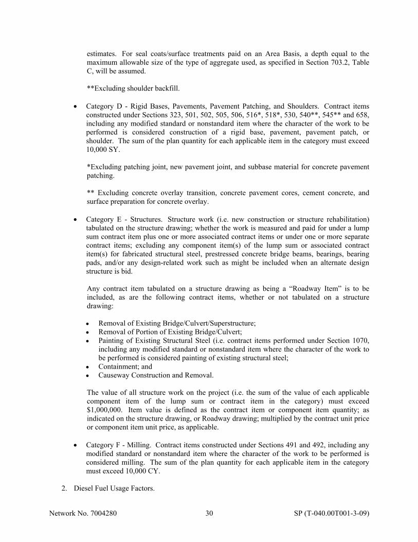
Network No. 7004280 30 SP (T-040.00T001-3-09)
estimates. For seal coats/surface treatments paid on an Area Basis, a depth equal to the maximum allowable size of the type of aggregate used, as specified in Section 703.2, Table C, will be assumed. **Excluding shoulder backfill.
Category D - Rigid Bases, Pavements, Pavement Patching, and Shoulders. Contract items
constructed under Sections 323, 501, 502, 505, 506, 516*, 518*, 530, 540**, 545** and 658, including any modified standard or nonstandard item where the character of the work to be performed is considered construction of a rigid base, pavement, pavement patch, or shoulder. The sum of the plan quantity for each applicable item in the category must exceed 10,000 SY.
*Excluding patching joint, new pavement joint, and subbase material for concrete pavement patching. ** Excluding concrete overlay transition, concrete pavement cores, cement concrete, and surface preparation for concrete overlay.
Category E - Structures. Structure work (i.e. new construction or structure rehabilitation)
tabulated on the structure drawing; whether the work is measured and paid for under a lump sum contract item plus one or more associated contract items or under one or more separate contract items; excluding any component item(s) of the lump sum or associated contract item(s) for fabricated structural steel, prestressed concrete bridge beams, bearings, bearing pads, and/or any design-related work such as might be included when an alternate design structure is bid.
Any contract item tabulated on a structure drawing as being a “Roadway Item” is to be included, as are the following contract items, whether or not tabulated on a structure drawing:
Removal of Existing Bridge/Culvert/Superstructure; Removal of Portion of Existing Bridge/Culvert; Painting of Existing Structural Steel (i.e. contract items performed under Section 1070,
including any modified standard or nonstandard item where the character of the work to be performed is considered painting of existing structural steel;
Containment; and Causeway Construction and Removal.
The value of all structure work on the project (i.e. the sum of the value of each applicable component item of the lump sum or contract item in the category) must exceed $1,000,000. Item value is defined as the contract item or component item quantity; as indicated on the structure drawing, or Roadway drawing; multiplied by the contract unit price or component item unit price, as applicable.
Category F - Milling. Contract items constructed under Sections 491 and 492, including any
modified standard or nonstandard item where the character of the work to be performed is considered milling. The sum of the plan quantity for each applicable item in the category must exceed 10,000 CY.
2. Diesel Fuel Usage Factors.
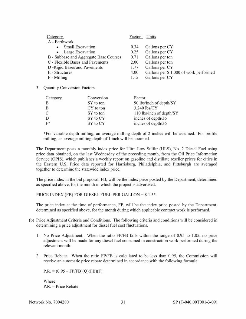
Network No. 7004280 31 SP (T-040.00T001-3-09)
Category Factor Units A - Earthwork
Small Excavation Large Excavation
0.34 0.25
Gallons per CY Gallons per CY
B - Subbase and Aggregate Base Courses 0.71 Gallons per ton C - Flexible Bases and Pavements 2.00 Gallons per ton D -Rigid Bases and Pavements 1.77 Gallons per CY E - Structures 4.00 Gallons per $ 1,000 of work performed F - Milling 1.15 Gallons per CY
3. Quantity Conversion Factors.
Category Conversion Factor B SY to ton 90 lbs/inch of depth/SY B CY to ton 3,240 lbs/CY C SY to ton 110 lbs/inch of depth/SY D SY to CY inches of depth/36 F* SY to CY inches of depth/36
*For variable depth milling, an average milling depth of 2 inches will be assumed. For profile milling, an average milling depth of 1 inch will be assumed.
The Department posts a monthly index price for Ultra Low Sulfur (ULS), No. 2 Diesel Fuel using price data obtained, on the last Wednesday of the preceding month, from the Oil Price Information Service (OPIS), which publishes a weekly report on gasoline and distillate reseller prices for cities in the Eastern U.S. Price data reported for Harrisburg, Philadelphia, and Pittsburgh are averaged together to determine the statewide index price. The price index in the bid proposal, FB, will be the index price posted by the Department, determined as specified above, for the month in which the project is advertised. PRICE INDEX (FB) FOR DIESEL FUEL PER GALLON = $ 1.55. The price index at the time of performance, FP, will be the index price posted by the Department, determined as specified above, for the month during which applicable contract work is performed.
(b) Price Adjustment Criteria and Conditions. The following criteria and conditions will be considered in
determining a price adjustment for diesel fuel cost fluctuations. 1. No Price Adjustment. When the ratio FP/FB falls within the range of 0.95 to 1.05, no price
adjustment will be made for any diesel fuel consumed in construction work performed during the relevant month.
2. Price Rebate. When the ratio FP/FB is calculated to be less than 0.95, the Commission will
receive an automatic price rebate determined in accordance with the following formula:
P.R. = (0.95 – FP/FB)(Q)(FB)(F) Where: P.R. = Price Rebate
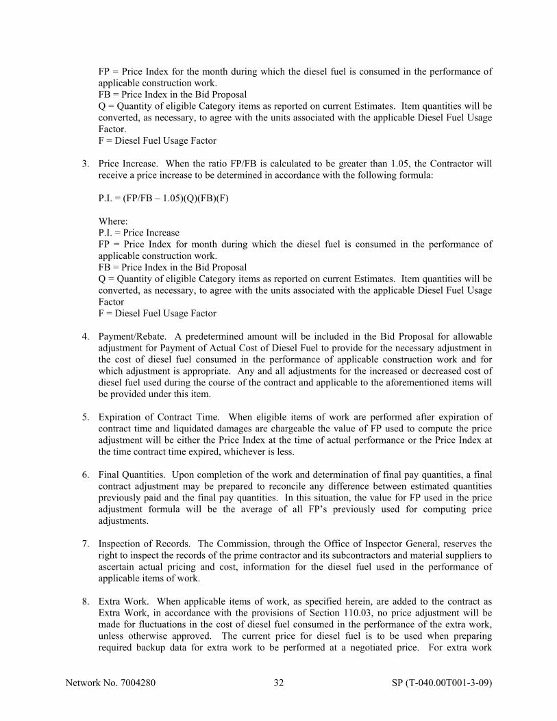
Network No. 7004280 32 SP (T-040.00T001-3-09)
FP = Price Index for the month during which the diesel fuel is consumed in the performance of applicable construction work. FB = Price Index in the Bid Proposal Q = Quantity of eligible Category items as reported on current Estimates. Item quantities will be converted, as necessary, to agree with the units associated with the applicable Diesel Fuel Usage Factor. F = Diesel Fuel Usage Factor
3. Price Increase. When the ratio FP/FB is calculated to be greater than 1.05, the Contractor will
receive a price increase to be determined in accordance with the following formula:
P.I. = (FP/FB – 1.05)(Q)(FB)(F) Where: P.I. = Price Increase FP = Price Index for month during which the diesel fuel is consumed in the performance of applicable construction work. FB = Price Index in the Bid Proposal Q = Quantity of eligible Category items as reported on current Estimates. Item quantities will be converted, as necessary, to agree with the units associated with the applicable Diesel Fuel Usage Factor F = Diesel Fuel Usage Factor
4. Payment/Rebate. A predetermined amount will be included in the Bid Proposal for allowable adjustment for Payment of Actual Cost of Diesel Fuel to provide for the necessary adjustment in the cost of diesel fuel consumed in the performance of applicable construction work and for which adjustment is appropriate. Any and all adjustments for the increased or decreased cost of diesel fuel used during the course of the contract and applicable to the aforementioned items will be provided under this item.
5. Expiration of Contract Time. When eligible items of work are performed after expiration of
contract time and liquidated damages are chargeable the value of FP used to compute the price adjustment will be either the Price Index at the time of actual performance or the Price Index at the time contract time expired, whichever is less.
6. Final Quantities. Upon completion of the work and determination of final pay quantities, a final
contract adjustment may be prepared to reconcile any difference between estimated quantities previously paid and the final pay quantities. In this situation, the value for FP used in the price adjustment formula will be the average of all FP’s previously used for computing price adjustments.
7. Inspection of Records. The Commission, through the Office of Inspector General, reserves the
right to inspect the records of the prime contractor and its subcontractors and material suppliers to ascertain actual pricing and cost, information for the diesel fuel used in the performance of applicable items of work.
8. Extra Work. When applicable items of work, as specified herein, are added to the contract as
Extra Work, in accordance with the provisions of Section 110.03, no price adjustment will be made for fluctuations in the cost of diesel fuel consumed in the performance of the extra work, unless otherwise approved. The current price for diesel fuel is to be used when preparing required backup data for extra work to be performed at a negotiated price. For extra work

Network No. 7004280 33 SP (T-040.00T001-3-09)
performed on force account basis, reimbursement for material, equipment, and service by others costs along with specified overhead and profit markups will be considered to include full compensation for the current cost of diesel fuel.
F06.00 PRICE ADJUSTMENT FOR STEEL COST FLUCTUATIONS (ITEM: 4000-1000) These requirements provide for a price adjustment, in the form of a payment to the Contractor or a rebate to the Commission, for fluctuations in the cost of the steel used in the applicable materials placed as part of the construction work specified in Sections 948, 1005, 1050, 1056, 1080 and 1085. (a) General. These price adjustment provisions apply to items in the contract Schedule of Prices, as
specified above, including any modified standard or non-standard item where the work to be performed includes incorporation of one or more of the applicable steel materials specified in the above Sections and addressed herein. Additionally, items in the lump sum breakdown for an “as-designed” or alternate design structure will be included when applying the specified price adjustment requirements, provided the work to be performed includes incorporation of one or more of the applicable steel materials specified in the above Sections and addressed herein. Steel hood plates for barriers; as well as pile tip reinforcement, high load multi-rotational bearings, expansion dams, shear connectors, and scuppers and downspouting; will not be subject to the price adjustment criteria and conditions specified herein.
The Department posts a monthly index price for steel ($ per ton) based on data obtained from the U.S. Department of Labor (USDOL), Bureau of Labor Statistics, which publishes monthly Producer Price Index (PPI) values for various commodities. The statewide index price for steel will be based on the PPI value posted by USDOL for “Semi-finished Steel Mill Products” (Series ID: WPU101702). The Department will post its monthly index price for steel after the USDOL lists the PPI value on which it is based as final.
The “base/benchmark” index price, SB, will be the steel index price posted by the Department, determined as specified above, for the month in which project letting occurred. The “invoice” index price, SI, will be the steel index price posted by the Department, determined as specified above, for the month in which applicable steel material is invoiced by the mill providing necessary raw steel materials. Steel material will be considered invoiced as of the date when an invoice from a steel mill is sent to the Contractor or to a subcontractor, fabricator, manufacturer or supplier. The steel price adjustment provisions specified herein are not applicable to raw steel material having a mill invoice date that precedes the project letting date. On a quarterly basis, provide documentation of the invoice date for applicable steel material incorporated into the work during the prior 3-month period. Documentation is to be in the form of a tabulation that lists all material invoiced during the period, in chronological order by invoice date; the quantity invoiced; and the applicable contract item(s) and corresponding project location(s) where the invoiced quantity or portion thereof was incorporated, along with copies of supporting invoices. Have a representative of the Contractor, authorized to make such statements, certify that the information provided in the tabulation is complete and accurate and may be relied upon by the Commission. Failure to provide the required tabulation within 10 calendar days of the end of each, applicable 3-month period will result in the Commission computing a price adjustment (rebate or increase) using a value for SI that results in the greatest possible price rebate or least possible price increase based on the monthly index prices posted by the Department, to date, since work on the project began.

Network No. 7004280 34 SP (T-040.00T001-3-09)
(b) Price Adjustment Criteria and Conditions. The following criteria and conditions will be considered in determining a price adjustment for steel cost fluctuations.
1. No Price Adjustment. When the ratio SI/SB falls within the range of 0.95 to 1.05, no price
adjustment will be made for applicable steel material having an invoice date that falls within the month for which the SI index price was posted.
2. Price Rebate. When the ratio SI/SB is calculated to be less than 0.95, the Commission will
receive an automatic price rebate, for applicable steel material having an invoice date that falls within the month for which the SI index price was posted, to be determined in accordance with the following formula:
P.R. = (0.95 – SI / SB) (SB) (ST)
where:
P.R. = Price Rebate SI = Index price for the month in which applicable steel material is invoiced. SB = Index price for the month in which project letting occurred. ST = Quantity (tons) of applicable steel material incorporated into the work during the
applicable 3-month period.*
*Computed based on the quantity paid, under applicable contract items, on current estimates processed during the 3-month period addressed in the tabulation provided by the Contractor. Not to exceed the total tonnage of applicable steel material invoiced during the month for which the SI index price was posted, as shown on the Contractor’s tabulation.
3. Price Increase. When the ratio SI/SB is calculated to be greater than 1.05, the Contractor will
receive a price increase, for applicable steel material having an invoice date that falls within the month for which the SI index price was posted, to be determined in accordance with the following formula:
P.I. = (SI / SB - 1.05) (SB) (ST)
where:
P.I = Price Increase SI = Index price for the month in which applicable steel material is invoiced. SB = Index price for the month in which project letting occurred. ST = Quantity (tons) of applicable steel material incorporated into the work during the
applicable 3-month period.*
* Computed based on the quantity paid, under applicable contract items, on current estimates processed during the 3-month period addressed in the tabulation provided by the Contractor. Not to exceed the total tonnage of applicable steel material invoiced during the month for which the SI index price was posted, as shown on the Contractor’s tabulation.
4. Equivalent Tonnage. For applicable steel material furnished under a separate contract item, the
equivalent steel tonnage will be computed as indicated in the following sections:
4.a Piles. For applicable steel beam bearing piles, cast-in-place concrete bearing piles, cast-in-place concrete piles, and steel pipe piles, furnished under a separate contract item or as an item associated with an alternate design structure, the equivalent tonnage is computed as follows:
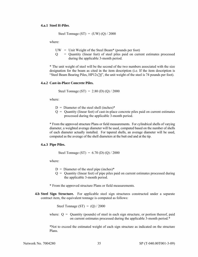
Network No. 7004280 35 SP (T-040.00T001-3-09)
4.a.1 Steel H-Piles.
Steel Tonnage (ST) = (UW) (Q) / 2000
where:
UW = Unit Weight of the Steel Beam* (pounds per foot) Q = Quantity (linear feet) of steel piles paid on current estimates processed
during the applicable 3-month period.
* The unit weight of steel will be the second of the two numbers associated with the size designation for the beam as cited in the item description (i.e. If the item description is “Steel Beam Bearing Piles, HP12x74”, the unit weight of the steel is 74 pounds per foot).
4.a.2 Cast-in-Place Concrete Piles.
Steel Tonnage (ST) = 2.80 (D) (Q) / 2000
where:
D = Diameter of the steel shell (inches)* Q = Quantity (linear feet) of cast-in-place concrete piles paid on current estimates
processed during the applicable 3-month period.
* From the approved structure Plans or field measurements. For cylindrical shells of varying diameter, a weighted average diameter will be used, computed based on the number of shells of each diameter actually installed. For tapered shells, an average diameter will be used, computed as the average of the shell diameters at the butt end and at the tip.
4.a.3 Pipe Piles.
Steel Tonnage (ST) = 6.70 (D) (Q) / 2000
where:
D = Diameter of the steel pipe (inches)* Q = Quantity (linear feet) of pipe piles paid on current estimates processed during
the applicable 3-month period.
* From the approved structure Plans or field measurements.
4.b Steel Sign Structure. For applicable steel sign structures constructed under a separate contract item, the equivalent tonnage is computed as follows:
Steel Tonnage (ST) = (Q) / 2000
where: Q = Quantity (pounds) of steel in each sign structure, or portion thereof, paid
on current estimates processed during the applicable 3-month period.* *Not to exceed the estimated weight of each sign structure as indicated on the structure Plans.

Network No. 7004280 36 SP (T-040.00T001-3-09)
4.c Fabricated Structural Steel. For applicable fabricated structural steel; furnished under a separate contract item or as an item associated with an "as-designed" or alternate design structure; the equivalent tonnage is computed as follows:
Steel Tonnage (ST) = (Q) / 2000
where: Q = Quantity (pounds) of fabricated structural steel girders, rolled beams,
angle, and plate paid on current estimates processed during the applicable 3-month period.
4.d Precast Reinforced Concrete Box Culverts and Prestressed Concrete Bridge Beams. For
applicable precast reinforced concrete box culvert segments and prestressed concrete bridge beams, furnished under a separate contract item or as an item associated with an "as-designed" or alternate design structure, the equivalent tonnage is computed as follows:
Steel Tonnage (ST) = (UW)(Q)/2000
where:
UW = Unit Weight (pounds per foot) of reinforcing steel in a box culvert segment or of reinforcing steel and prestressing strands in a prestressed bridge beam.*
Q = Quantity (linear feet) of precast reinforced concrete box culvert segments and prestressed concrete bridge beams paid on current estimates processed during the applicable 3-month period.
* Submit documentation indicating the weight (pounds) of reinforcing steel included in and the length (feet) of each box culvert segment, and the weight (pounds) of mild reinforcing steel and prestressing strands included in and the length (feet) of each prestressed bridge beam. UW will be computed as the average of the unit weight of steel (i.e. weight of steel divided by length) in each box culvert segment, or as the average of the unit weight of steel (i.e. weight of steel divided by length) in each prestressed bridge beam. Documentation must be submitted at the time required shop drawings are submitted for approval.
5. Payment/Rebate. A predetermined amount will be included in the Schedule of Prices for Price
Adjustment for Steel Cost Fluctuations to provide for the necessary adjustment in the cost of steel used in applicable construction work and for which adjustment is appropriate. Any and all adjustments for the increased or decreased cost of steel used during the course of the contract and applicable to the aforementioned items will be provided under this item.
6. Expiration of Contract Time. When eligible materials are purchased after expiration of contract
time and liquidated damages are chargeable, the value for SI used to compute the price adjustment will be either the index price for the month in which applicable steel material is invoiced or the index price at the time contract time expired, whichever is less.
7. Final Quantities. Upon completion of the work and determination of final pay quantities, a final
contract adjustment may be prepared to reconcile any difference between estimated quantities previously paid and the final quantities. In this situation, the value for SI used in the price adjustment formula will be the average of all SI values previously used for computing price adjustments.

Network No. 7004280 37 SP (T-040.00T001-3-09)
8. Inspection of Records. The Commission, through the Office of Inspector General, reserves the right to inspect the records of the prime contractor and its subcontractors and material fabricators and suppliers to ascertain actual invoicing dates and quantity information for the steel material used in the performance of applicable items of work.
9. Extra Work. When applicable items of work, as specified herein, are added to the contract as
Extra Work, in accordance with the provisions of Section 110.03, no price adjustment will be made for fluctuations in the cost of the steel used in manufacturing the materials placed during performance of the extra work. The current price for steel is to be used when preparing required backup data for extra work to be performed at a negotiated price. For extra work performed on a force account basis, reimbursement of actual material costs, along with the specified overhead and profit markup, will be considered to include full compensation for the current cost of steel.
F07.00 COMPLIANCE WITH PERMIT REQUIREMENTS 04/01/16 The stream work to be performed as part of this project is covered under the Pennsylvania Department of Environmental Protection's Water Obstruction and Encroachment Permit and the U.S. Army Corps of Engineers' PASPGP-5 Permit. These permits have been secured by the Commission and are included with the contract documents as Attachment C. The sewer relocation work to be performed as part of this project is covered under the Pennsylvania Department of Environmental Protection's Water Obstruction and Encroachment Permits and the associated U.S. Army Corps of Engineers' Permits. These permits have been secured by the respective sewer authorities and are included with the contract documents in Attachments L and M. Comply with the conditions stipulated in the permits. The erosion and sediment pollution control plans and narrative contained in the contract documents have been reviewed and approved by the Allegheny County Conservation District. A copy of the letter is included in Attachment D. The contractor is to comply with the plans. Any change to the erosion and sediment pollution control plan must be approved by the Representative and the Allegheny County Conservation District. Temporary pollution control measures, in addition to those shown on the drawings, may be ordered by the Representative. Perform this work as specified in Section 845. Waste areas, both within Turnpike Right-of-Way and outside Turnpike Right-of-Way, must have proper erosion and sedimentation control devices installed and maintained. This may require a permit from the Allegheny County Conservation District. The Contractor is required to obtain any permits for waste areas outside the Turnpike Right-of-Way. Any waste areas within the Turnpike Right-of-Way must be approved by the Commission and the Contractor will be responsible for preparing all permit applications for submission by the Commission. The Commission assumes no liability for waste areas within the Right-of-Way not approved by the appropriate local, state or federal agency. F08.00 PROJECT COLLABORATION SYSTEM All submittals, documentation, meeting minutes, and correspondence will be handled electronically via the Commission’s project collaboration system, Kahua. There are costs associated with a Kahua Platform License and Construction Document Management License, as well as with some of the other, optional Kahua Applications. In addition, there are costs associated with setting up and training people to use Kahua. Visit the Kahua kStore for pricing information (http://www.kahua.com).
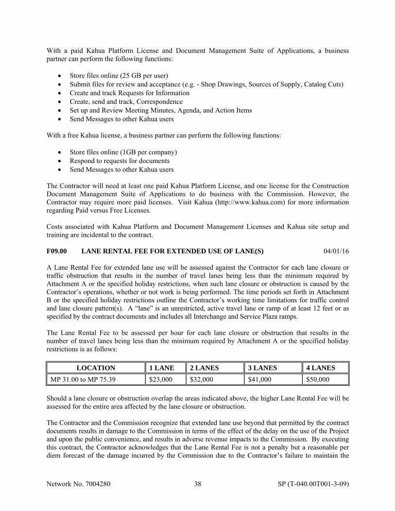
Network No. 7004280 38 SP (T-040.00T001-3-09)
With a paid Kahua Platform License and Document Management Suite of Applications, a business partner can perform the following functions:
Store files online (25 GB per user) Submit files for review and acceptance (e.g. - Shop Drawings, Sources of Supply, Catalog Cuts) Create and track Requests for Information Create, send and track, Correspondence Set up and Review Meeting Minutes, Agenda, and Action Items Send Messages to other Kahua users
With a free Kahua license, a business partner can perform the following functions:
Store files online (1GB per company) Respond to requests for documents Send Messages to other Kahua users
The Contractor will need at least one paid Kahua Platform License, and one license for the Construction Document Management Suite of Applications to do business with the Commission. However, the Contractor may require more paid licenses. Visit Kahua (http://www.kahua.com) for more information regarding Paid versus Free Licenses. Costs associated with Kahua Platform and Document Management Licenses and Kahua site setup and training are incidental to the contract. F09.00 LANE RENTAL FEE FOR EXTENDED USE OF LANE(S) 04/01/16 A Lane Rental Fee for extended lane use will be assessed against the Contractor for each lane closure or traffic obstruction that results in the number of travel lanes being less than the minimum required by Attachment A or the specified holiday restrictions, when such lane closure or obstruction is caused by the Contractor’s operations, whether or not work is being performed. The time periods set forth in Attachment B or the specified holiday restrictions outline the Contractor’s working time limitations for traffic control and lane closure pattern(s). A “lane” is an unrestricted, active travel lane or ramp of at least 12 feet or as specified by the contract documents and includes all Interchange and Service Plaza ramps. The Lane Rental Fee to be assessed per hour for each lane closure or obstruction that results in the number of travel lanes being less than the minimum required by Attachment A or the specified holiday restrictions is as follows:
LOCATION 1 LANE 2 LANES 3 LANES 4 LANES
MP 31.00 to MP 75.39 $23,000 $32,000 $41,000 $50,000 Should a lane closure or obstruction overlap the areas indicated above, the higher Lane Rental Fee will be assessed for the entire area affected by the lane closure or obstruction. The Contractor and the Commission recognize that extended lane use beyond that permitted by the contract documents results in damage to the Commission in terms of the effect of the delay on the use of the Project and upon the public convenience, and results in adverse revenue impacts to the Commission. By executing this contract, the Contractor acknowledges that the Lane Rental Fee is not a penalty but a reasonable per diem forecast of the damage incurred by the Commission due to the Contractor’s failure to maintain the
Network No. 7004280 39 SP (T-040.00T001-3-09)
requisite minimum number of lanes open to unobstructed travel as called for by Attachment A or the specified holiday restriction. When it becomes evident that the Contractor’s operation(s) will result in extended lane use and a Lane Rental Fee, the Representative will direct the Contractor to take immediate action to bring the Project into conformance with Attachment A or the specified holiday restriction. The Contractor’s operations will be suspended until the Contractor demonstrates to the satisfaction of the Representative that proper measures, including adequate planning, scheduling and coordination, have been taken to complete the operations within working time and lane closure limitations. No contract time extension will be granted for suspension of any operation which resulted in a Lane Rental Fee assessment. Any request for extension of allowable hours without assessment of the Lane Rental Fee must be pre-approved by the Representative prior to implementation of the lane closure. Approval of any individual request will not be considered a precedent for approval or denial of any future requests. The Representative will be the sole authority for determination of Lane Rental Fees. The entire amount will be assessed for any portion of the hour for which a lane closure or obstruction exists. The Commission will have the right to apply as payment for such Lane Rental Fees any money which is due to the Contractor by the Commission. At the discretion of the Representative, the Lane Rental Fee may be waived or reduced for failure to open the minimum number of travel lanes if such cause is beyond the control of the Contractor, i.e., Act of God, catastrophic events, accidents not related or caused by the Contractor’s operations. The waiver or reduction of Lane Rental Fees will not operate as a waiver on the part of the Commission of any of its rights under the contract. F10.00 RETIME EXISTING TRAFFIC SIGNALS
(ITEM: 4000-0030) F10.01 Description - This work, if it is deemed necessary by the Commission during the scheduled
detour, is making changes to signal controller interval timings and coordination settings at the following existing signals along the detour route: SR 8 & Bardonner Rd Ext. / E. Bardonner Rd SR 8 & W. Hardies Rd / E. Hardies Rd
F10.03 Construction - Contact the Commission, PennDOT District 11, and Hampton Township a
minimum of two weeks in advance of the start of the scheduled detour. If deemed necessary, the Commission will provide to the contractor the traffic signal timings and coordination settings to be implemented.
Keep a record of each change made at a particular controller in that controller cabinet. The record consists of a copy of the timing and phasing diagram and includes the date, the change made, the name and phone number of the person authorizing the change, and the name of the person making the change.
Return timings to original settings upon completion of work.
Make a note of the signal timings and coordination settings that are in place at the controller before implementing the initial change. Check the existing timing settings and verify they are as indicated on the most recent record. Notify the Representative if unauthorized timing changes have been made. Provide a copy of each change of record.
During the detour, perform signal timing and coordination setting changes as directed within 24 hours of notification.
Network No. 7004280 40 SP (T-040.00T001-3-09)
Within 24 hours of the end of the detour, return the traffic signal to the signal timing and coordination changes that were in place prior to the start of the detour.
F10.04 Measurement and Payment – Each. Measured as visit to each intersection.
The provisions of Section 110.02(d) do not apply to this item due to the contingent nature of the work being performed.
F11.00 MAINTENANCE AND PROTECTION OF TRAFFIC (ITEM: 2901-0001) F11.01 Description - This work is the furnishing, installing, maintaining, resetting, relocating,
storing, and removal of all traffic control devices necessary for maintenance and protection of traffic during construction.
F11.03 Construction - Perform maintenance and protection of traffic according to Section 901, PTS (900, 960, 980),
the contract drawings and the special provisions. Furnish, install and maintain all required lights, guides, sandbags and appurtenances as
deemed necessary by the Representative for the proper maintenance and protection of traffic and to warn of any obstruction or hazard to traffic. Use Type A and Type B flasher units and Sequential Warning Lights on this project. Furnish, install and maintain all shadow vehicles. Shadow vehicles without a truck mounted attenuator must be a 33,000 lb GVW (Gross Vehicle Weight) or larger vehicle and loaded to weigh a minimum of 22,000 lbs. in addition to meeting the requirements of Publication 212.
Provide signs with PennDOT approved Type XI reflectorized material.
Utilize the following general procedures for maintenance and protection of traffic:
A. For Pre-Construction Signing: Erect these signs prior to the performance of any work that may affect or alter the normal traffic pattern on the Turnpike.
1. Erect MPT-33, CAUTION - NEW TRAFFIC PATTERNS - NEXT X MILES at the
approaches to the work zone. In addition, erect R22-1 signs, WORK ZONE STATE LAW TURN ON HEADLIGHTS, as the first sign approaching the work zone.
Furnish, install and maintain an adequate post-mounted sign support system that will retain the signs in-place during the course of the project. PennDOT approved Type III barricades may be used as conditions warrant and as directed by the Representative.
Maintain, relocate, and repair all signs, including necessary replacement. At the conclusion of the project, remove all temporary signs and mountings and properly repair and restore the area.
2. Erect W20-1 and other signs at the approaches (from 2 miles) to the work limits for
each physical work zone with appropriate legends as indicated on PTS-900 to warn traffic of construction to be encountered. For physical work zones that are being worked on concurrently that are less than 2 miles apart, provide a portable changeable

Network No. 7004280 41 SP (T-040.00T001-3-09)
message sign approximately 1 mile in advance of the physical work zone; message as approved by the Representative. R2-1 sign at the end of the first work zone is to be 55 MPH when followed by additional work zones, only when the physical work zones are less than 2 miles apart. Erect W21-20 signs, END ACTIVE WORK ZONE, immediately at the end of the first active work zone. Post G20-2 sign at the end of the final work zone. Portable changeable message signs required for the approach signing are incidental to the Maintenance and Protection of Traffic. Post mount signs at locations designated by the Representative in such a manner as not to obstruct shoulders and be clear of work areas. Relocate approach signing as work progresses. Erect W21-19 signs, ACTIVE WORK ZONE WHEN FLASHING INCREASED PENALTIES, when workers are present on the roadway, berm, or shoulder and not protected by concrete barrier. Do not erect the sign within a transition or at a location where workers are put at risk when they may need to turn the light on and off. When there is more than one active work zone separated by a distance of more than 1 mile, erect signs for each active work zone. Attach a PennDOT approved white Type B high-intensity flashing light to the upper portion of each W21-19 sign. Activate the white Type B high-intensity flashing light only when workers are present on the roadway, berm, or shoulder and not protected by concrete barrier and turn off the white Type B high-intensity flashing light when workers are not present on the roadway, berm, or shoulder for 60 minutes or more or are protected by concrete barrier. Cover the W21-19 and W21-20 signs during non-working hours. Erect W21-20 signs, END ACTIVE WORK ZONE, immediately at the end of each active work zone, except this sign is not necessary if the G20-2, END ROAD WORK, sign is installed at the end of the active work zone. Provide a PennDOT approved Speed Display Sign ½ to 1 mile in advance of the physical work zone to advise motorists of their vehicle’s speeds. Provide two (2) additional PennDOT approved Speed Display Signs, one (1) located 500 to 900 feet in advance of the physical work zone, and one (1) located at the midpoint of the physical work zone to advise motorists of their vehicle’s speeds. The Contractor may furnish additional units. Trim trees and vegetation, and remove all obstructions at each placement site. The locations and times of operation are as approved by the Representative. The R22-1, W21-19, and W21-20 signs, the white Type B high-intensity flashing light, and the Speed Display Sign have been created by PennDOT in response to the requirements of Act 229. These signs and devices, as well as the associated guidelines, can be found in 67 PA Code, Chapter 212, Official Traffic Control Devices. Review, familiarize, and apply these guidelines and all its supplements to this construction project as required by Act 229. Mount MPT-14, CONSTRUCTION BETWEEN INTERCHANGES …, and MPT-15, TURNPIKE CONSTRUCTION BETWEEN INTERCHANGES …, signs in the vicinity of the Cranberry Interchange (MP 28), the Butler Valley Interchange (MP 39), the Allegheny Valley Interchange (MP 48), and the Pittsburgh Interchange (MP 57) to advise motorists using or intending to use the Turnpike of construction to be encountered. A minimum of one week prior to placing concrete barrier to be used in the Maintenance and Protection of Traffic, post these signs on the shoulders to inform customers of upcoming construction work at locations as directed by the
Network No. 7004280 42 SP (T-040.00T001-3-09)
Representative. Remove signs when concrete barrier is no longer used in the Maintenance and Protection of Traffic. Mount MPT-14 signs in advance of the Turnpike eastbound lanes before the Cranberry Interchange (MP 28) and Butler Valley Interchange (MP 39). Mount MPT-14 signs in advance of the Turnpike westbound lanes before the Allegheny Valley Interchange (MP 48), and the Pittsburgh Interchange (MP 57). Mount MPT-15 signs along PA 8 before the Butler Valley Interchange (MP 39) and PA 28 before the Allegheny Valley Interchange. Coordinate with any PennDOT Districts and local government agencies for the erection of MPT-15 signs along the noted roadways. Inform and copy the Representative of all correspondence relating to the MPT-15 signs.
Use PTS-900, Sheets 5 and 6 of 13, Mobile Operation for 2 and 3 Lanes, to cover and uncover signs and install and remove traffic control devices. Provide an additional Shadow Vehicle with arrow panel to be used with PTS-900, Sheets 5 and 6 of 13, Mobile Operation for 2 and 3 Lanes, as needed. During nighttime hours, provide 1 Multi-Directional Lighting Device on Shadow Vehicle(s) with Truck Mounted Attenuator and each of the Work Vehicle(s).
B. Do not exceed a maximum work zone of 4 miles in length for operations not behind
barrier. In the event a 4 mile work zone for operations not behind barrier is not required or the work zone is not used in an efficient manner, the Representative will direct the length of the work zone be shortened to that length sufficient for the Contractor's operation and efficiency. Maintain a minimum of 2 miles of unrestricted roadway between patterns on the same side of the road.
1. Furnish, operate, and maintain in the following manner, additional safety devices and
controls for operation adjacent to traffic patterns: a. Furnish equipment working adjacent to traffic with a yellow flashing light
attached to the equipment to indicate its outer limit, visible 360 degrees. Lights are to be according to Section 901.
b. Mount vertical panels with Type A lights at the approach end, facing traffic, of
all shoulder inlets, guide rail ends, and bridge parapet ends whenever traffic is using the shoulder or part of the shoulder as a travel lane.
c. Place vertical panels at 25 foot intervals for 150 feet in advance of each Vehicle
Attenuating Terminal End Treatment (VATET) during traffic control stages in which traffic will operate on shoulders adjacent to guide rail and VATETs.
2. Use PennDOT approved vertical panels with self-ballasting bases for channelizing
devices. The entire face of the vertical panel visible to traffic is to be reflectorized with PennDOT approved Type XI reflectorized material. Completely remove channelizing devices from the roadway so they are not visible to motorists during non-working hours. Channelizing devices may be temporarily relocated to the minimum offset to allow for work to be performed, as directed by the Representative. The channelizing

Network No. 7004280 43 SP (T-040.00T001-3-09)
devices must remain between traffic and the work zone. Relocate channelizing devices to original position as work progresses. Channelizing devices may remain in the median during median reconstruction as indicated in this specification.
3. Lane restrictions will not be permitted during non-working hours for any operation requiring either a mobile lane restriction or a stationary lane or shoulder restriction.
4. The maximum pavement differential for this project is 2-inches.
5. If both lanes in one direction are open to traffic and a differential between right and
left lane pavement exist, install W8-11 (UNEVEN LANES) signs on the left shoulder and the right shoulder 1,500 feet in advance of where the pavement differential begins. Locate W8-11 signs on the right shoulder at ½-mile intervals throughout the area where the pavement differential exists, as directed by the Representative. In addition, locate W8-11 signs on the acceleration ramps of Interchanges and Service Plazas where the pavement differential exists, as directed by the Representative. Program a message on the Portable Changeable Message Sign as shown on the PTS-900 located approximately 1 mile in advance of the work zone indicating the pavement differential. The suggested message is “UNEVEN LANES, MOTORCYCLES USE CAUTION”.
6. If traffic is restricted to the left lane and the vertical dropoff between the left and right lane is greater than 2-inches, provide Emergency Pull-Offs according to Special Provision B02.00, Emergency Pull-Offs, during Stage 2 Phase A or Stage 2 Phase B at an approximate spacing of 1 mile each direction. Provide a wedge of milled material at 1 inch per foot along the length of the Emergency Pull-Off at no additional cost. Removal of the wedge is incidental to the Maintenance and Protection of Traffic.
7. Maintain the entrances and exits to Interchanges, Service Plazas, Maintenance Sheds
and Access Ramps at all times. If traffic is crossing the closed lane and a pavement differential exists, provide, of sufficient width, a paved 1 inch per foot wedge to remove the vertical drop-off at the entrances and exits to Interchanges, Service Plazas, Maintenance Sheds and Access Ramps. If traffic is running on the milled lane and a pavement differential exists, provide a paved 1 inch per foot wedge to remove the vertical drop-off at the entrances and exits to Interchanges, Service Plazas, Maintenance Sheds and Access Ramps for the full length of the ramps. Providing temporary paving and the milling off of the wedge is incidental to the Maintenance and Protection of Traffic.
8. Install a R4-12 (TRUCKS BUSES RIGHT (LEFT) LANE ONLY) for eastbound
traffic on the left shoulder and the right shoulder 2,500 feet in advance of where the lane shift begins during Stage 2 Phase B. Locate R4-12 signs on the right shoulder at ½-mile intervals throughout the area where traffic has been shifted during Stage 2 Phase B, as directed by the Representative. Program a message on the Portable Changeable Message Sign as shown on the PTS-900 located approximately 1 mile in advance of the work zone indicating the restriction. The suggested message is “TRUCKS AND BUSES, LEFT LANE ONLY NEXT X MI”. Coordinate with the Turnpike Operations Center for the posting of a message related to the restriction on its permanent Dynamic Message Signs. In addition, locate R4-12 sign with R3-9DP (END) on the right shoulder at the end of this condition.
Network No. 7004280 44 SP (T-040.00T001-3-09)
Install a R4-12 (TRUCKS BUSES RIGHT (LEFT) LANE ONLY) for eastbound traffic on the left shoulder and the right shoulder 2,500 feet in advance of where the lane shift begins during Stage 3. Locate R4-12 signs on the right shoulder at ½-mile intervals throughout the area where traffic has been shifted during Stage 3, as directed by the Representative. Program a message on the Portable Changeable Message Sign as shown on the PTS-900 located approximately 1 mile in advance of the work zone indicating the restriction. The suggested message is “TRUCKS AND BUSES, LEFT LANE ONLY NEXT X MI”. Coordinate with the Turnpike Operations Center for the posting of a message related to the restriction on its permanent Dynamic Message Signs. In addition, locate R4-12 sign with R3-9DP (END) on the right shoulder at the end of this condition. Install a R4-12 (TRUCKS BUSES RIGHT (LEFT) LANE ONLY) for westbound traffic on the left shoulder and the right shoulder 2,500 feet in advance of where the lane shift begins during Stage 3. Locate R4-12 signs on the right shoulder at ½-mile intervals throughout the area where traffic has been shifted during Stage 3, as directed by the Representative. Program a message on the Portable Changeable Message Sign as shown on the PTS-900 located approximately 1 mile in advance of the work zone indicating the restriction. The suggested message is “TRUCKS AND BUSES, LEFT LANE ONLY NEXT X MI”. Coordinate with the Turnpike Operations Center for the posting of a message related to the restriction on its permanent Dynamic Message Signs. In addition, locate R4-12 sign with R3-9DP (END) on the right shoulder at the end of this condition.
9. All pavement patches must be backfilled with the specified patching material and to the level of the existing adjacent roadway surface during non-working hours.
10. Arrange construction operations so that no portion of the median (excluding slow
speed ramps) is without barrier (concrete or MB-2B) between opposing travel lanes or that any blunt end of the median barrier is exposed to oncoming traffic.
11. Backfill the median in tangent areas so that the dropoff does not exceed 2 inches
from the edge of adjacent pavement during periods when traffic is running adjacent to the median (hours requiring all lanes of traffic). Backfill the median in superelevated areas so that the dropoff does not exceed 3½ inches from the edge of adjacent pavement during periods when traffic is running adjacent to the median (hours requiring all lanes of traffic). Place vertical panels in the median during the non-working hours. Space vertical panels at 50-foot maximum spacing on the inside and outside of horizontal curves.
12. If the shoulder work zone is not behind temporary concrete barrier, backfill all
shoulders and excavated areas adjacent to the right lane so that the dropoff does not exceed 2 inches from the existing adjacent pavement and complete any required slope improvements, guide rail, abutment transition piece, or concrete barrier installations prior to opening the right lanes for traffic. All inlet repairs, replacements or installations must be complete or covered with a single steel plate prior to opening the right lane to traffic. If the right lane must be opened to traffic and any of the aforementioned conditions are not met, install temporary concrete barrier per PTS-900 and as approved by the Representative, at the Contractor's expense, to separate motorists from these conditions.
Network No. 7004280 45 SP (T-040.00T001-3-09)
13. If the right lane is open to traffic and a differential between the right lane and shoulder pavement exists, install a W8-9 (LOW SHOULDER) sign on the right shoulder 1,500 feet in advance of where the pavement differential begins. Locate W8-9 signs on the right shoulder at ½-mile intervals throughout the area where the pavement differential exists, as directed by the Representative. In addition, locate W8-9 signs on the acceleration ramps of Interchanges and Service Plazas where the pavement differential exists, as directed by the Representative.
14. Provide portable changeable message sign on the right shoulder approximately 1 mile
in advance of any pavement differential, message as directed by the Representative.
15. Commission Maintenance Forces will install flex-post delineation for non-concrete barrier areas on the right shoulder of the travel lanes, unless otherwise specified for particular items of work. Notify the Representative 2 weeks prior to any stage or phase change and allow 1 week of unrestricted access for completion of the installation.
16. Where the traffic will operate on shoulders adjacent to guide rail, install reflectors at
permanent spacing, 75 feet on tangent and 37.5 feet on curves, before shifting traffic to the affected areas.
17. When traffic will operate on median or shoulder, secure all inlet grates in the travel
lane or within 2 feet of the travel lane. Provide a grate securing system for approval. Ensure all inlets are accessible when traffic no longer uses the median or shoulder.
18. Install, reset, relocate, and remove any permanent and/or temporary concrete barrier
so that no blunt end of the barrier is exposed to oncoming traffic. Temporary concrete barrier used must be manufactured after October 1, 2002.
19. Locate temporary impact attenuating devices a minimum of 2 feet from the edge line
for shoulder installations.
20. Pin temporary concrete barrier or glare screen used to separate motorists from the work zone when the back edge of the median barrier or glare screen is less than 12” from the work zone and the dropoff into the work zone is greater than 12” in depth. The temporary concrete barrier or glare screen must be pinned for non-movement.
21. Remove existing and/or temporary pavement markers that conflict with revised traffic patterns and may confuse motorists. Remove by methods that will cause the least damage to the pavement surface. Existing pavement marker types include Snowplowable Raised Pavement Markers (SRPM) and Recessed Reflective Pavement Markers (RRPM). Temporary pavement marker types include RRPM and non-plowable raised markers.
a. Removal of existing SRPMs, which includes both the reflector and the shoe, and
removal of RRPMs will require patching of the roadway. Patch the roadway to the satisfaction of the Representative.
b. Removal of temporary RRPMs and non-plowable raised markers may require
patching of the roadway. Patch the roadway to the satisfaction of the Representative.

Network No. 7004280 46 SP (T-040.00T001-3-09)
c. Remove only the reflectors for existing SRPMs and RRPMs when traffic will be returned to their normal lanes at the end of the construction. Clean the area to allow for the proper installation of new reflectors for existing SRPMs and RRPMs.
22. All stoppages and pacing of traffic as well as their associated coordination with
Troop T of the Pennsylvania State Police must be approved and coordinated through the Representative a minimum of fourteen (14) days prior and confirmed with the Representative within the last 48 hours. Pacing will only be allowed during allowable single lane hours.
23. For a minimum of two (2) weeks prior to utilizing Turnpike traffic stoppage(s) or
pace(s), program the portable changeable message signs to provide the proposed date of traffic stoppage(s) or pace(s) and to provide for advance notification of anticipated traffic stoppage(s) or pace(s).
24. Utilize (1) westbound Turnpike traffic stoppage of a maximum of two (2) hours
between the available hours of 12:00 AM and 5:00 AM to perform the installation of the half span sign structure at MP 42.76
a. All Turnpike traffic stoppages must occur on a Sunday morning. b. Turnpike traffic stoppages will not be permitted during the Holiday Periods listed
in Attachment B. c. Traffic will be stopped on the Turnpike mainline only by the Turnpike detail of
the Pennsylvania State Police. Should it become apparent that the required work will not be completed within the allotted two (2) hour stoppage, the Representative will direct the Contractor to cease operations, stabilize the remaining or new structure and open to traffic as soon as possible.
d. Turnpike traffic stoppages will only be allowed during satisfactory weather
conditions as determined by the Turnpike detail of the Pennsylvania State Police. e. The Commission will assess road user damages according to Special Provision
F13.00, Road User Costs for the two (2) hour Turnpike traffic stoppage. f. The Representative will be responsible for keeping the official time for the
purpose of assessments of road user costs. g. Notify the Representative of the intent to stop traffic a minimum of thirty (30)
days in advance of the scheduled work and have sufficient flaggers with vehicles available during these periods to assist the Turnpike detail of the Pennsylvania State Police. The flaggers are subject to the direction and control of the Turnpike detail of the Pennsylvania State Police.
h. During the traffic stoppage, position two (2) Shadow Vehicles with Truck
Mounted Attenuators in the travel lanes as directed by the Representative. Position the vehicles in the travel lanes as directed by the Representative. These vehicles and any additional items are incidental to Item 2901-0001.
Network No. 7004280 47 SP (T-040.00T001-3-09)
25. A milled surface must be paved with the final wearing course within 48 hours of the surface being milled. The final wearing course must be placed on milled surfaces in the travel lanes prior to any holiday periods.
C. Utilize the following sequences to perform all work between MP 39.07 and MP 47.78.
Pre-Stage 1 – Pavement Patching, Milling, and Paving
1. During allowable working hours, close the eastbound or westbound right or left lanes
by placing channelizing devices 2-feet into the right or left lanes as shown on PTS-900 and complete pavement patching, milling, and wearing course west of MP 44.04. Use Typical Interchange and Service Plans Signing For Single Lane Traffic Patterns for work in the vicinity of interchanges.
2. During allowable working hours, close the eastbound or westbound right or left lanes by placing channelizing devices 2-feet into the right or left lanes as shown on PTS-900 and perform the work described in Special Provision F58.00, Milling and Repaving Near Allegheny Valley Interchange. Use Typical Interchange and Service Plans Signing For Single Lane Traffic Patterns for work in the vicinity of interchanges.
Stage 1 Phase A – Eastbound and Westbound Shoulder Work
1. During allowable working hours, close the right lane by placing channelizing devices 2-feet into the right lane as shown on PTS-900.
2. Reconstruct sections of the existing shoulder as shown on the Traffic Control Plans.
Stage 1 Phase B – Median Reconstruction and Barrier Installation
1. During allowable working hours, close the westbound left travel lane by placing channelizing devices 2-feet into the left lane as shown on PTS-900 and Traffic Control Plans and install temporary concrete glare screen as shown on Traffic Control Plans.
2. During allowable working hours, close the eastbound left lane by placing channelizing devices 2-feet into the right lane as shown on PTS-900 and reconstruct sections of the existing median as shown on the Traffic Control Plans.
Stage 2 Phase A – Outside Mainline Construction
1. During allowable working hours, close the eastbound and westbound right lanes by placing channelizing devices 2-feet into the right lanes as shown on PTS-900 and install temporary concrete barrier as shown on Traffic Control Plans. Provide a proper end treatment for the concrete barrier.
2. During allowable working hours, close the left lane in both the eastbound and
westbound directions as shown on PTS-900 and reset temporary concrete glare screen that was installed in Stage 1 in the median as shown on Traffic Control Plans.
3. Construct outside sections of Turnpike Mainline as shown on plans.

Network No. 7004280 48 SP (T-040.00T001-3-09)
Stage 2 Phase B – Outside Mainline Construction – Westbound western tie in and Westbound Relocation Area
1. During allowable working hours, install an additional run of temporary concrete barrier
in the eastbound direction as shown on Traffic Control Plans. Provide a proper end treatment for the concrete barrier.
2. Shift eastbound traffic onto the roadway constructed in Stage 2 Phase A. Relocate
eastbound temporary barrier installed in Stage 2 Phase A. 3. During allowable working hours, close the westbound right lane by placing channelizing
devices 2-feet into the right lane as shown on PTS-900 and reset temporary concrete barrier for the location shown on Traffic Control Plans.
4. Construct outside sections of Turnpike Mainline as shown on plans.
Stage 3 Inside Mainline Construction 1. During allowable working hours, install additional runs of temporary concrete barrier in
the westbound direction as shown on Traffic Control Plans. Provide a proper end treatment for the concrete barrier.
2. Shift westbound traffic onto the roadway constructed in Stage 2 Phase A/B. Remove
westbound temporary barrier installed in Stage 2 Phase A. Eastbound traffic remains in Stage 2 Phase B pattern.
3. During allowable working hours, close the left lane in the westbound direction as shown
on PTS-900 and reset temporary concrete glare screen as shown on Traffic Control Plan. 4. Construct inside portion of Turnpike Mainline as shown on plans.
5. For a minimum of two (2) weeks prior to sign structure installation, program the
portable changeable message signs to provide the proposed date of installation, and to provide advance notification of anticipated resultant traffic stoppages.
6. Install the half span sign structure at MP 42.76. Utilize one (1) westbound Turnpike
traffic stoppage of a maximum of two (2) hours between the hours of 12:00 AM to 5:00 AM. Use changeable message signs during stoppages.
Anti-Graffiti Coating of Overhead Structures During allowable hours, close the eastbound or westbound center lane (if applicable) and the right or left lanes by placing channelizing devices 2-feet into the center (if applicable) and right or left travel lanes as shown on PTS-900 and perform work described in Special Provision F55.00, Anti-Graffiti Coating. Final Wearing Course and Pavement Applications on Turnpike Complete the final milling and construct the final wearing course. Install SNAP and Highly Reflectorized Polyurea Pavement Markings. Use Typical Interchange and Service Plans Signing For Single Lane Traffic Patterns for work in the vicinity of interchanges.
Network No. 7004280 49 SP (T-040.00T001-3-09)
F11.04 Measurement and Payment - Lump Sum. F12.00 DETOUR OF EAST BARDONNER ROAD AND BEN HERR STREET F12.01 Description - This work is the installing, maintaining, and removing of the detour route for
maintenance and protection of local traffic on East Bardonner Road (T-600) and Ben Herr Street (T-601) during construction of Bridge WB-421.
F12.03 Construction –
The detour may not be put into effect until after the last day of school in the Hampton Township School District, which will not be before June 12, 2017.
According to the Traffic Control Plan, sign for the closing of East Bardonner Road under the Pennsylvania Turnpike. Erect all signs and cover existing signs as indicated prior to the closing of East Bardonner Road and Ben Herr Street to traffic. Any R11-2, R11-3, R11-4, W20-2, and W20-3 series signs are to have a Type B flashing light as part of the installation.
Arrange with PennDOT and Hampton Township for necessary inspection prior to
implementing the traffic control pattern. Notify PennDOT District 11-0 at Bridgeville, PA, and the Hampton Township
Supervisors at least 2 weeks in advance of the closing of East Bardonner Road and Ben Herr Street.
Coordinate all work with local officials, schools, and emergency services. Notify
appropriate personnel at these agencies at least 2 weeks in advance of the closing of East Bardonner Road and Ben Herr Street.
Provide a W23-101 sign ("THIS ROAD TO BE CLOSED FOR CONSTRUCTION")
with the appropriate date based on the Contractor's schedule. Place the sign on Type III barricades in both directions in advance of Bridge WB-421 at East Bardonner Road 2 weeks prior to the start of construction. Remove the signs at the start of the project.
Maintain constant surveillance of the traffic control operation and replace or correct any
missing, damaged, ineffective, or misaligned equipment to the satisfaction of the Representative.
All distances may be adjusted slightly to fit field conditions. Maintain access to adjacent properties at all times at existing driveway access points. Relocate mailboxes as necessary throughout construction. Maintain access to fire
hydrants and utilities. All property owners and agencies listed below must be contacted in writing by certified
mail at least 2 weeks prior to closing East Bardonner Road and Ben Herr Street. It is the Contractor's responsibility to make these contacts. Copy the Representative on this correspondence. Attempt to acquire any phone numbers not listed below so that

Network No. 7004280 50 SP (T-040.00T001-3-09)
notification of these persons/agencies can be made if there is a scheduling change for closing East Bardonner Road and Ben Herr Street. The notifications by phone must take place at least 24 hours prior to the scheduled closing.
The following list of persons and agencies is the minimum number of contacts that must
be made prior to detouring East Bardonner Road and Ben Herr Street. Additional contacts may be required by the Representative, the Commission, any Emergency Service Agency, or at the Contractor's discretion.
LIST OF MANDATORY CONTACTS PRIOR TO DETOURING Pennsylvania Department of Transportation Hampton Township Volunteer Fire Dept. Engineering District 11-0 2536 Duncan Ave 45 Thoms Run Road Bridgeville, PA 15017 Allison Park, PA 15101 (412) 429-4912 (412) 487-1114 Attn: Michael Sokol, Lou Ruzzi, & Brian Myler Attn: Robert Skertich, Fire Chief Port Authority of Allegheny County (PAAC) Hampton Township EMS 345 6th Avenue PO Box 833 Pittsburgh, PA 15222-2541 Allison Park, PA 15101 (412) 566-1385 (412) 486-2007 Allegheny County Hampton Township 436 Grant Street 3101 McCully Road Pittsburgh, PA 15219 Allison Park, PA 15101 (412) 350-4005 (412) 486-0400 Attn: Stephen Shanley, Director of Public Works Attn: Christopher Lochner, Municipal
Manager Monark Student Transportation Corporation Hampton Township School District 5374 William Flynn Highway 4591 School Drive Gibsonia, PA 15044 Allison Park, PA 15101 Attn: Doug Starr (412) 492-6308 (724) 898-3563 Attn: Jeffrey Kline, [email protected] Director of Administrative Services Hampton Township Police Department 3101 McCully Road Allison Park, PA 15101 (412) 486-0400
F12.04 Measurement and Payment – All materials, labor, and work for installing, maintaining, and removing the detour route are incidental to Maintenance and Protection of Traffic (Item 2901-0001).
F13.00 ROAD USER COSTS 04/01/16 The Contractor must utilize one (1) 2-hour uni-directional traffic stoppage according to Special Provision F11.00, Maintenance and Protection of Traffic to perform the erection of half-span DMS structure S42.76WB at MP 42.76.

Network No. 7004280 51 SP (T-040.00T001-3-09)
The Commission will assess road user damages in the amount of $2,000.00 westbound per each five (5) minutes beyond each permissible time period specified for traffic stoppages allotted to complete the operation and open to traffic. The time period exceeding the permissible time periods specified for stoppages will be rounded up to the next 5-minute increment. The Representative will be responsible for tracking the time. Should it become apparent that the erection of half-span DMS structure S42.76WB at MP 42.76 will not be completed within the maximum time period specified, the Representative will direct the Contractor to cease operations, stabilize the structure and open traffic as soon as possible. The stabilization of the structure will be at the direction of the Representative and will not be reimbursed by the Turnpike Commission. Additional traffic stoppages for the erection of the remaining portion(s) of the structure will be considered as time beyond the allotted stoppage and will be assessed road user costs accordingly. The additional stoppage will not be permitted until the Contractor can demonstrate to the Representative an acceptable method and procedure sufficient to complete the erection in a safe and efficient manner. F14.00 PROTECTION AND COORDINATION OF UTILITIES 04/01/16 Ascertain and locate any utility lines including Commission owned facilities, in the vicinity of the entire project and take all precautions to fully protect the (utility) facility and service. Prior to performing any work in the vicinity of any underground or overhead line or service, advise the facility owner at least 72 hours in advance of initiating work and provide all measures for protection in accordance with the National Electric Safety Code, the Occupational Safety and Health Administration's Regulations and as deemed necessary by the facility owner with the Representative's concurrence. Coordinate protection and relocation of utilities with the facility owner. Attention is directed to the Provisions of Act 287 of 1974 and subsequent amendments which specify the responsibilities in regard to public health and safety during excavation and demolition operations in areas of underground utilities. Contact the One Call System at 1-800-242-1776 for all facilities prior to performing underground work. Immediately report to the facility owner including the Commission any break, leak or other damage to the lines or protective coatings made or discovered during the work and immediately alert the occupants of the premises and the employees of any emergency created or discovered. The Commission may have both underground and aerial utility facilities within the project limits, specifically the Maintenance, Interchange, Tunnel, and Service Plaza areas. In addition to service lines, the Commission has lighting and various other facilities throughout the Turnpike system. The Commission's Tradesman Superintendent may be able to provide information about these sites and can be contacted through the Representative. Perform all work required for the location, replacement, adjustment or reconstruction of underground utilities in accordance with Section 105.06. This work is incidental to the project. Cooperate with all facility owners in the protection, placement, replacement, relocation, adjustment, or reconstruction of their structures and facilities during construction. Contact all facility owner representatives at least 15 working days prior to starting construction, and all affected utilities at least 3 weeks in advance of any required facility movements or as identified in the following description, in order to schedule and coordinate operations. The anticipated type of utility work is as follows:

Network No. 7004280 52 SP (T-040.00T001-3-09)
PRIOR: The Commission anticipates completion before the Notice to Proceed is issued. Actual or anticipated date is shown. RESTRICTIVE: To be completed by the (UTILITY) FACILITY OWNER before operating without restriction. Number of calendar days required AFTER THE DATE OF NOTICE TO PROCEED. CONCURRENT: Simultaneous with, but not restricting operations. Number of calendar days required. COORDINATED: Phasing with specific operations. Number of calendar days required AFTER COMPLETION OF SPECIFIC CONSTRUCTION OPERATIONS. NOT AFFECTED: Identifies (UTILITY) FACILITY OWNERS with facilities in the construction area which are not anticipated to be affected. Specific information may be provided by the (UTILITY) FACILITY OWNER. INCORPORATED: Facility relocation work to be incorporated into the prime highway construction contract. CONDITIONAL CONDITIONS AND TIME REQUIREMENTS: Identify the conditions affecting the facility owner’s ability to perform work. i.e. certain times of the day, week or year that a facility cannot be shut down, acquisition of R/W by the Turnpike, demolition of buildings, relocation of other facilities, etc. Number of calendar days required. Anticipated (utility) facility owner involvement, facility owner/contractor performing work, locations of work, and type of work are identified below. Number of calendar days required. BUCKEYE PARTNERS, L.P. Project Contact: Rob McCrea (412) 327-3801& e-mail: [email protected] Construction Contact: Field Operations Manager (412) 264-7432 NOT AFFECTED (U/G) I-76 Sta. 713+42 – 10-inch petroleum line in 18-inch casing. The Utility’s representative must be present while working in the area of their pipeline. Contact the Field Operations Manager five (5) working days in advance to arrange for their inspector to be present. COMCAST Project/Constr. Contact: Kent Norton (412) 352-7045 & e-mail: [email protected] COORDINATED (Aerial) I-76 Sta. 554+31, LT. Construct sound wall leaving sufficient panels out to permit the Utility to attach an aerial guy to a new temporary Duquesne Light Company guy pole so that their existing anchor rod can be removed to accommodate the excavation for the proposed 18-inch drainage pipe. Notify the Utility two (2) weeks in advance of needing the anchor rod removed. Fourteen (14) calendar days required to complete. COORDINATED (Aerial) I-76 Sta. 554+31, LT. Construct Basin 554 and associated drainage pipes. The Utility will then install a new anchor rod and guy wire and remove their temporary aerial guy. Notify the Utility two (2) weeks in advance of needing the temporary aerial guy removed. Fourteen (14) calendar days required to complete. NOT AFFECTED (Aerial) I-76 Sta. 603+16. NOT AFFECTED (Aerial) I-76 Sta. 737+00.
Network No. 7004280 53 SP (T-040.00T001-3-09)
NOT AFFECTED (Aerial) I-76 Sta. 756+00. NOT AFFECTED (Aerial) I-76 Sta. 780+62. CONSOLIDATED COMMUNICATIONS Project/Constr. Contact: Jeff Hall (724) 443-9639 & e-mail: [email protected] Construction Contact: John Thorpe (724) 443-9619 PRIOR (Aerial) I-76 Sta. 558+68. The Utility will remove cables after installing underground conduit/cable to accommodate the construction of the proposed structure extension. Work Completed. NOT AFFECTED (Aerial) I-76 Sta. 603+16. DQE COMMUNICATIONS Project/Construction Contact: Shawn Ross (412) 315-0929 & e-mail: [email protected] PRIOR (Aerial) I-76 Sta. 558+68. The Utility will remove cables after installing underground conduit/cable to accommodate the construction of the proposed structure extension. Work completed. NOT AFFECTED (Aerial) I-76 Sta. 737+00. NOT AFFECTED (Aerial) I-76 Sta. 756+00. NOT AFFECTED (Aerial) I-76 Sta. 780+62. DEER CREEK DRAINAGE BASIN AUTHORITY Project/ Constr. Contact: Chuck DeBaldo (724) 265-5315 (O), (412) 913-6684 (C), & e-mail: [email protected] NOT AFFECTED (U/G) I-76 Sta. 657+00 to Sta. 658+00, LT – 8-inch sanitary sewer line. NOT AFFECTED (U/G) I-76 Sta. 665+50, LT – 8-inch sanitary sewer line. RESTRICTIVE (U/G) I-76 Sta. 674+50, LT. The Utility will install a temporary by-pass pump station to facilitate the work specified in Special Provision F88.00, DCDBA Sewer Construction. Contact the Utility two (2) weeks prior for delivery and installation of a temporary bypass pump(s). Two (2) calendar days required for the Utility to install the by-pass pump. INCORPORATED (U/G) I-76 Sta. 674+50, LT. and Sta. 676+00, RT. Remove and reinstall 8” sanitary sewer pipe to accommodate the excavation for the proposed culvert extension construction as specified in Special Provision F88.00, DCDBA Sewer Construction. NOT AFFECTED (U/G) I-76 Sta. 685+50, RT – 8-inch sanitary sewer line. NOT AFFECTED (U/G) I-76 Sta. 701+00 to Sta. 703+00, RT – 8-inch sanitary sewer line. NOT AFFECTED (U/G) I-76 Sta. 710+50 to Sta. 729+01, RT – 8-inch and 10-inch sanitary sewer line. NOT AFFECTED (U/G) I-76 Sta. 751+38 – 12-inch sanitary sewer line in 20-inch Casing.
Network No. 7004280 54 SP (T-040.00T001-3-09)
DUQUESNE LIGHT COMPANY Project/Construction Contact: Robby Frantz (412) 393-7813 & e-mail: [email protected] NOT AFFECTED (Aerial) I-76 Sta. 551+63, LT. COORDINATED (Aerial) I-76 Sta. 554+31, LT. Construct sound wall leaving sufficient panels out to permit the Utility to install a new temporary guy pole and guy wire so that their existing anchor rod can be removed to accommodate the excavation for the proposed 18-inch drainage pipe and Basin 554. Notify the Utility four (4) weeks in advance of needing the anchor rod removed. Fourteen (14) calendar days required to complete. COORDINATED (Aerial) I-76 Sta. 554+31, LT. Construct Basin 554 and associated drainage pipes. The Utility will then install a new anchor rod and guy wire and remove their temporary aerial guy. Notify the Utility four (4) weeks in advance of needing the temporary aerial guy removed. Fourteen (14) calendar days required to complete. NOT AFFECTED (Aerial) I-76 Sta. 558+68. NOT AFFECTED (Aerial) I-76 Sta. 603+16. NOT AFFECTED (Aerial) I-76 Sta. 737+00. NOT AFFECTED (Aerial) I-76 Sta. 756+00. NOT AFFECTED (Aerial) I-76 Sta. 780+62. HAMPTON SHALER WATER AUTHORITY Project/Constr. Contact: Sam Scarfone (412) 486-4867 & e-mail: [email protected] NOT AFFECTED (U/G) I-76 Sta. 553+00, LT – 1-inch and 8-inch water line. PRIOR (U/G) I-76 Sta. 557+05 to Sta. Sta. 558+55, LT. The Utility will relocate their 8-inch water main pipeline to accommodate the excavation for the proposed drainage inlets and pipe, retaining wall, and structure footing. Work Completed. PRIOR (U/G) T-600 Sta. 18+60 to Sta. 22+15, LT. The Utility will relocate/replace their 6-inch water main pipeline to accommodate the excavation for the proposed bridge extension footing. Work Completed. NOT AFFECTED (U/G) I-76 Sta. 601+76 – 16-inch water line with 30-inch casing. HAMPTON TOWNSHIP Project/Constr. Contact: Jim Degnan (412) 486-0400 x-312 & e-mail: [email protected] COORDINATED (U/G) T-600 Sta. 21+30, LT and Sta. 21+49, RT. Provide the amount of vertical adjustment. The Utility will adjust their manhole frames and covers to the required final grade. One (1) calendar day required to complete. INCORPORATED (U/G) I-76 Sta. 558+90 to Sta. 560+10, LT. Install 8-inch sanitary sewer main pipeline to accommodate the excavation for the proposed culvert extension footing as specified in Special Provision F87.00, Hampton Township Sewer Construction. NOT AFFECTED (U/G) I-76 Sta. 559+75 – 8-inch sanitary sewer line.
Network No. 7004280 55 SP (T-040.00T001-3-09)
INCORPORATED (U/G) I-76 Sta. 586+21, LT. Remove and reinstall 8-inch sanitary sewer pipe to accommodate the excavation for the proposed culvert extension construction as specified in Special Provision F87.00, Hampton Township Sewer Construction. RESTRICTIVE (U/G) I-76 Sta. 586+21, LT. The Utility will install and maintain a temporary by-pass pumping system to facilitate the work specified in Special Provision F87.00, Hampton Township Sewer Construction. Contact Jim Degnan two (2) weeks in advance to schedule the installation of a by-pass pumping system. Two (2) calendar days required for the Utility to install a by-pass pumping system. HERE Chicago Project/Constr. Contact: Alexandra Archer (312) 257-8904 & e-mail: [email protected] COORDINATED (Aerial) I-76 Sta. 574+89, RT. Notify the Utility sixty (60) days in advance of grading operations. Perform grading and field stake the location of the outside edge of the proposed travel lane. The Utility will remove pole and coordinate an acceptable new pole location with the Representative and the Contractor to accommodate the proposed roadway widening. Three (3) calendar days required to complete.
COORDINATED (Aerial) I-76 Sta. 661+97, LT. Notify the Utility sixty (60) days in advance of grading operations. Perform grading and field stake the location of the back of the proposed guide rail post. The Utility will remove pole and coordinate an acceptable new pole location with the Representative and the Contractor to accommodate the proposed roadway widening. Three (3) calendar days required to complete. NOT AFFECTED (U/G) I-76 Sta. 734+19, RT. OAKMONT WATER AUTHORITY Project Contact: Jack Dunlap, General Manager (412) 828-7220 and e-mail: [email protected] Constr. Contact: Jim McCaskey (412) 327-0096 & e-mail: [email protected] NOT AFFECTED (U/G) I-76 Sta. 754+20 – abandoned 8-inch water line. NOT AFFECTED (U/G) I-76 Sta. 758+63 – 12-inch water line. NOT AFFECTED (U/G) I-76 Sta. 782+50 – abandoned 6-inch water line in 14-inch casing. NOT AFFECTED (U/G) I-76 Sta. 782+81 – 12-inch water line. PEOPLES NATURAL GAS COMPANY, LLC Project Contact: Diane McKee (412) 244-2507 & e-mail: [email protected] Constr. Contact: Nick DiPietro (412) 258-4478 & e-mail: [email protected] PRIOR (U/G) T-600 Sta. 22+04, RT. The Utility will construct a new regulator station so that the existing regulator station can be removed. Anticipated completion: February 28, 2017. NOT AFFECTED (U/G) T-600 Sta. 18+50 to Sta. 21+92, LT – abandoned 4-inch gas line. PRIOR (U/G) T-600 Sta. 21+18, LT. to Sta. 22+02, RT. The Utility will cut-off and abandon their 4-inch gas pipeline to accommodate the excavation for the proposed drainage inlet after installing a new 4-inch gas pipeline from the new regulator station, across East Bardonner Rd. (T-600, sta. 21+94), and tie-into their existing pipeline along Ben Herr Street. Anticipated completion: February 28, 2017.

Network No. 7004280 56 SP (T-040.00T001-3-09)
PRIOR (U/G) T-600 Sta. 20+50 to Sta. 22+08, RT. The Utility will cut-off and abandon their 4-inch gas pipeline to accommodate the excavation for the proposed drainage inlet and bridge extension footing after installing a new 4-inch gas pipeline from the new regulator station and tie-into their existing pipeline along East Bardonner Rd. (T-600). Anticipated completion: February 28, 2017. PRIOR (U/G) I-76 Sta. 559+25 to Sta. 561+69, LT. The Utility will cut-off and abandon their 12-inch gas pipeline to accommodate the excavation for the proposed culvert extension footing after installing a new 12-inch gas pipeline. The new 12-inch gas main pipeline will also be tied-in to the new regulator station. Anticipated completion: February 28, 2017. PRIOR (U/G) T-600 Sta. 18+55 to Sta. 22+08, LT/RT and I-76 Sta. 559+23 to 561+69, LT. The Utility will purge and cap their abandoned gas pipelines and remove the old regulator station (I-76 Sta. 559+40, LT). Anticipated completion: February 28, 2017. NOT AFFECTED (U/G) I-76 Sta. 563+08 – 12-inch gas line in 20-inch casing. NOT AFFECTED (U/G) I-76 Sta. 603+00 to Sta. 606+26, LT – 3-inch gas line. NOT AFFECTED (U/G) I-76 Sta. 606+68 – abandoned 6-inch casing. NOT AFFECTED (U/G) I-76 Sta. 754+27 – 6-inch gas line in 12-inch casing. NOT AFFECTED (U/G) I-76 Sta. 754+27 to 755+62, RT – 6-inch gas line. NOT AFFECTED (U/G) I-76 Sta. 782+35 – abandoned 3-inch gas line in 8 5/8-inch casing. NOT AFFECTED (U/G) I-76 Sta. 782+88 – 4-inch gas line. SUNESYS, LLC Project Contact: David Davis (412) 462-4561 x-205 & e-mail: [email protected] Construction Contact: Aaron Phillips (412) 462-4561 x-2352 & e-mail: [email protected] NOT AFFECTED (Aerial) I-76 Sta. 603+16. VERIZON PENNSYLVANIA, INC. Project/Constr. Contact: Gary Redondo (412) 237-2293 & e-mail: [email protected] NOT AFFECTED (Aerial) I-76 Sta. 726+55. NOT AFFECTED (Aerial) I-76 Sta. 756+00. NOT AFFECTED (Aerial) I-76 Sta. 780+62. NY STATE NATURAL GAS COMPANY Contact: None available NOT AFFECTED (U/G) I-76 Sta. 750+40 – abandoned 1-inch gas line in 4-inch casing. PRIVATE PIPELINES Contact: None available NOT AFFECTED (U/G) I-76 Sta. 623+41 – abandoned 1-inch gas line.

Network No. 7004280 57 SP (T-040.00T001-3-09)
(U/G) I-76 Sta. 624+28, LT. Vertically adjust abandoned gas well vent pipe as specified in Special Provision F86.00, Adjust Gas Well Vent Pipe. NOT AFFECTED (U/G) I-76 Sta. 735+00 – abandoned 1-inch water line. NOT AFFECTED (U/G) I-76 Sta. 775+65 – abandoned 1-inch water line in 2-inch casing. F15.00 EXPLORATORY EXCAVATION TO LOCATE GAS PIPELINE
(ITEM: 4000-0200) F15.01 Description - This work is locating an existing 12-inch gas main pipeline/20-inch steel casing
pipe at approximate Sta. 563+21 Lt., as directed. F15.03 Construction –
Excavate or employ other means as necessary to locate the existing Peoples Natural Gas (PNG) pipeline in preparation for the work specified in Item 1006-0207, 36" Diameter Drilled Caissons, Shaft Section in Soil, and Item 1006-0306, 30" Diameter Drilled Caissons, Rock Socket. Do not damage the existing pipeline or casing pipe. Hand excavate as required. Provide the Representative with a surveyed location of the pipeline/casing pipe at approximately offset 45’ Lt. Use this information and the following previously obtained subsurface location data (Sta. 563+24.82, Offset 106.63’ Lt, top of casing 6.80’ deep) to determine where the pipeline/casing pipe will cross the proposed sound barrier wall.
A PNG representative must be present during this work. Contact Mr. Lee Uncapher at 724-444-3238 at least two weeks in advance of performing the test hole excavation to schedule a PNG representative to be present.
Adjust caisson locations as required to avoid affecting the gas main pipeline. Backfill and compact as specified in Section 206. Do not damage gas pipeline when backfilling.
F15.04 Measurement and Payment – Cubic Yard. F16.00 FELLING OF TREES Trees will be felled by others prior to Notice to Proceed. The Contractor is responsible to remove the trees and stumps as part of clearing and grubbing work. Included with Item 2201-0001, Clearing and Grubbing. F17.00 REMOVAL OF IBC MEDIAN BARRIER
(ITEM: 4000-0010) F17.01 Description – This work is the removal and disposal of existing International Barrier
Corporation (IBC) median barrier. F17.03 Construction – Completely remove and dispose of existing IBC median barrier including the
existing coarse aggregate fill. F17.04 Measurement and Payment – Linear Foot.
Network No. 7004280 58 SP (T-040.00T001-3-09)
F18.00 REMOVAL OF ROCK FALL FENCE (ITEM: 4000-0011)
F18.01 Description – This work is the removal and disposal of existing rock fall fence. F18.03 Construction – Completely remove and dispose of existing rock fall fence posts, fence, and
foundations. F18.04 Measurement and Payment – Linear Foot. F19.00 REMOVAL OF PAVEMENT BASE DRAINS AND PAVEMENT BASE DRAIN
OUTLETS Remove and dispose of existing pavement base drains, pavement base drain outlets, subsurface drains, and subsurface drain outlet endwalls encountered within the limits of construction. Backfill areas of removal in accordance with Section 206.3. This work is incidental to Item 2203-0001 Class 1 Excavation. F20.00 RELOCATION OF EXISTING SIGNS 04/01/16 (ITEMS: 2930-1004 AND 2931-1001) F20.01 Description - This work consists of the removal of existing signs of the type specified and all
associated installation material and reinstallation of existing signs with new associated installation material located within the project limits and as warranted by construction operations.
F20.02 Material –
(a) Post Mounted Signs, Type A - Section 930.2, except delete the first bullet in Section 930.2(a). (b) Post Mounted Signs, Type B - Section 931.2, except delete the first bullet in Section 931.2.
F20.03 Construction -
(a) General. The removal and reinstallation of the existing signs must occur on the same day unless otherwise approved by the Representative. Relocate the signs as close to the original location as allowed by the construction operations and as directed by the Representative. Replace any signs lost or damaged through careless operations at no additional cost to the Commission.
(b) Post Mounted Signs, Type A. Construct the new foundations prior to the relocation of
the existing signs. Provide new posts, foundations, and associated hardware to be set at the location specified by the Representative. Remove the existing signs, posts, anchors, and associated hardware as directed by the Representative.
(c) Post Mounted Signs, Type B. Prepare the area prior to the relocation of the existing
signs. Provide new breakaway steel posts and associated hardware to be set at the location specified by the Representative. Remove the existing signs, breakaway steel posts, and associated hardware as directed by the Representative.
F20.04 Measurement and Payment –
(a) Relocation of Post Mounted Signs, Type A - Each. Includes all hardware, foundations, breakaway posts, and removal of existing foundations.
(b) Relocation of Post Mounted Signs, Type B - Each. Includes all hardware and breakaway steel posts.
Network No. 7004280 59 SP (T-040.00T001-3-09)
F21.00 ROCK ARMOR 04/01/16 (ITEM: 2850-0040) F21.01 Description – This work is the construction of rock armor to protect steep slopes along
shoulders. F21.02 Material – Rock, Class R-4 – Section 850.2 F21.03 Construction – Place rock armor in accordance with the details, PTS-124, Section 850.3 and
as directed by the Representative. F21.04 Measurement and Payment – Linear Foot, measured along the edge of the shoulder. Includes
excavation and rock. F22.00 REPLACEMENT OF DAMAGED GUIDE RAIL COMPONENTS
(ITEMS: 2620-0525, 2620-0548 AND 2620-0575) F22.01 Description – This work is the removal and disposal of damaged guide rail elements, offset
brackets, and guide rail posts and replacement with new components. F22.02 Material – Section 620.2 F22.03 Construction – Section 620.3 and as follows:
At the direction of the Representative, replace guide rail elements, offset brackets, and guide
rail posts damaged by traffic. Removal and disposal of damaged components is incidental to the component being replaced.
F22.04 Measurement and Payment –
(a) Offset Brackets – Each. (b) Guide Rail Posts – Each. (c) Guide Rail Element – Each – Includes removal and disposal of existing elements and
hardware, delineation and the realignment of posts. F23.00 REHABILITATION OF EXISTING PIPE CULVERT (ITEMS: 4601-0001 AND 4601-0002) F23.01 Description – This work is the rehabilitation of an existing pipe culvert by lining with a
snapped together, high-density polyethylene pipe (HDPE). F23.02 Material –
(a) Pipe – High-density polyethylene (HDPE) resin in accordance with ASTM D-3350-98a with a cell classification of PE 345464C and a Plastic Pipe Institute designation of PE 3408. Comply with the dimension of ASTM F-714 with a minimum DR of 32.5. The pipe shall have a smooth, non-corrugated interior and exterior, have a consistent inside and outside diameter, be resistant to the effects of UV rays, and be capable of being joined into continuous lengths.
(b) Pipe Joints - Must contain a gasket, be watertight and meet ASTM D-3212. (c) Grout – Section 601.2(c).
Network No. 7004280 60 SP (T-040.00T001-3-09)
F23.03 Construction -
Work must be performed under bypass flow in accordance with the Erosion and Sediment Pollution Control Plans. Clean the existing pipe culvert using high pressure or other mechanical means. The existing pipe culvert must be free of rocks, gravel, and other debris prior to the rehabilitation work. Install HDPE pipe liner as per the manufacturer’s instructions. Fill the annular spaces between the new liner and the existing pipe culvert as per the manufacturer’s recommendations using flowable grout. Connect to existing or proposed pipes, endwalls, headwalls, or inlets in accordance with the construction plans.
F23.04 Measurement and Payment – Linear Foot for the pipe liner size indicated.
Includes HDPE liner and installation, and grouting. F24.00 JACKED PIPE
(ITEMS: 4601-0003, 4601-0004, AND 4601-0005) F24.01 Description – This work is the construction of thermoplastic pipe inside a jacked and bored
steel casing pipe. F24.02 Material –
(a) Thermoplastic Pipe – Section 601.2(a)6c for the size indicated. (b) Casing Pipe – ASTM A709, yield Strength = 50 ksi, minimum wall thickness 0.5”, sized
to accommodate the thermoplastic pipe. (c) Grout – Section 601.2(c)
F24.03 Construction – Section 601.3, as directed by the Representative, and as follows:
Fill the annular spaces between the thermoplastic pipe and the inside of the steel casing with flowable grout. If necessary, cut casing pipe and thermoplastic pipe to install and connect with median inlet in a future stage of construction.
F24.04 Measurement and Payment – Linear Foot of casing pipe for the thermoplastic pipe size indicated. Includes excavation and cutting of casing pipe and thermoplastic pipe to install median inlet.
F25.00 PIPE EXTENSION CONNECTOR (ITEM: 4000-0608) F25.01 Description – This work is the furnishing and construction of connecting permanent pipeline
extensions to existing culvert pipes as shown and directed. F25.02 Material –
Network No. 7004280 61 SP (T-040.00T001-3-09)
(a) Concrete Collar – Section 618.2, sized to match existing pipe (b) Connector Band – Material and size to match existing pipe as approved by the Representative (c) Flowable Backfill, Type C – Section 220.2 (d) Class A Concrete – Section 704.1(b) (e) Pipe – Section 601.2
F25.03 Construction – As indicated, as directed by the Representative, and as follows: Submit a plan for this task to the Representative for approval prior to starting this item of
work. Schedule the work when existing stream flow is low. Utilize cofferdam and bypass pumping where necessary.
Remove the existing endwalls, as directed. Cut the existing pipe to a true edge as required to
make a satisfactory joint. Join the new pipe to the existing pipe or endwalls, using acceptable concrete collars constructed of Class A Concrete or acceptable metal connecting bands. Clean the existing pipe, according to Section 601.3(j). Repair or replace existing pipe damaged during construction. As an alternate to removing the endwall, if permitted, extend the pipe using a concrete collar for pipe extension, as specified in Section 618.2 and as shown on RC-32M.
F25.04 Measurement and Payment – Each. The unit price includes the excavation, the bedding material, coarse aggregate, removal of
existing structures, concrete collar or metal connection band, re-grading and backfill. Also includes shoring and trench box when necessary. Furnishing personnel and equipment for dewatering operations, inspection of pipes, and all remedial measures are incidental to the pipe items. If the pipe item for shore/trench box is indicated or required; the unit price includes placement and removal or keeping in place of shoring, supports, shield systems and trench boxes as specified in Section 601.3(g). The pipe will be paid for under separate items.
F26.00 TEMPORARY 6” PERFORATED DRAIN, SPECIAL (ITEM: 4901-0010) F26.01 Description – This work is the installation of a perforated drain at the interface between roadway
construction stages as detailed on the Contract Drawings and as directed by the Representative. F26.02 Material –
(a) Pavement Base Drain – Section 610.2 (b) No. 8 and No. 57 Aggregate – Section 703.2 (c) Geotextile, Class 1 – Section 735
F26.03 Construction – As shown on the drawings, as directed by the Representative and as follows:
Sequence the location and quantity of Geotextile, Class 1, No. 8 and No. 57 Coarse Aggregate as detailed on the contract drawings. Protect the pavement base drain and the subbase and asphalt treated base layers placed in Stages from infiltration of fine soil particles by maintaining the geotextile and coarse aggregate.
F26.04 Measurement and Payment – Linear Foot.
Includes excavation, pavement removal, backfill, pipe, geotextile, coarse aggregate, changing the position of geotextile and aggregate per the sequence of construction, maintaining and
Network No. 7004280 62 SP (T-040.00T001-3-09)
replacing geotextile and aggregate as necessary and connecting to existing and proposed pipes and/or inlets and removal of No. 57 Aggregate as required.
F27.00 TEMPORARY FLEXIBLE PIPE CONNECTION (ITEM: 4000-0610) F227.01 Description – This work is the furnishing, installing, maintenance, and removal of temporary
pipe connectors located at the interface of roadway construction Stage 2 with Stage 3. F27.02 Material –
(a) Geotextile, Class 2, Type A – Section 735.1 (b) Adjustable band – Material approved by the Representative (c) Flowable Backfill, Type B – Section 220.2 (d) Miscellaneous Pipe Fittings – Section 601.2
F27.03 Construction – As indicated, as directed by the Representative, and as follows: Submit a plan for the installation of the temporary flexible pipe connector to the Representative
for approval. The plan shall also define how the Contractor will establish and cut the necessary pipe length for Stage 2 construction to achieve the pipe joint at the Stage 2 to Stage 3 interface.
Stage 2 – 1. Complete Stage 2 trench work for placement of the cross pipes. 2. Support face of excavation as required to retain the Stage 3 work area while making the
temporary connection between old and new cross pipes. 3. Block the flow through the existing pipe for a period not to exceed one work day. 4. Form a watertight connection between the ends of the existing and proposed pipe by
placing and banding a single layer of Class 2, Type A Geotextile. Place a one-foot overlap at the bottom and sew the seam as specified in Section 212.3(c). For pipes of different sizes, use reducer fittings as needed.
5. Place flowable backfill as needed or directed.
Stage 3 – 1. Excavate the trench for extending the cross pipe. 2. Remove the flexible pipe connector and extend the proposed pipe across the construction
area of Stage 3.
F27.04 Measurement and Payment – Each. Includes supporting of adjacent excavation, pipe cutting, geotextile connector banded to pipe, flowable backfill, removal of the flexible connector. Also, includes the preparation of a plan for performing this item of work for approval by the Representative.
F28.00 TEMPORARY PIPE EXTENSION AND TEMPORARY INLET (ITEMS: 4000-0644 AND 4000-0645) F28.01 Description – This work is the furnishing, placement, maintenance, and removal of temporary
pipe extensions or inlets for the maintenance of existing drainage during construction as shown or as directed.

Network No. 7004280 63 SP (T-040.00T001-3-09)
F28.02 Material –
(a) Pipe – Section 601.2. Match existing pipe type or size if not indicated on the plans. (b) Connector Band – Material to match existing pipe as approved by the Representative. (c) Flowable Backfill, Type C – Section 220.2 (d) Temporary Inlet – Section 605.2 (e) Class A Concrete – Section 704.1(b)
F28.03 Construction – As indicated, as directed by the Representative, and as follows:
Furnish and install temporary pipe as indicated or directed in accordance with Section 601.3. Furnish and install temporary inlet as indicated or directed in accordance with Section 605.3.
Submit a plan for this task to the Representative for approval prior to starting this item of work. Schedule the work when existing flow is low. Utilize sandbag cofferdam and temporary pumping where necessary.
Remove the existing endwalls and/or inlet, as directed. Cut the existing pipe to a true edge, as required, to make a satisfactory joint. Join the new pipe to existing pipe or endwalls using acceptable collars constructed of Class A Concrete or acceptable metal connecting bands. Clean the existing pipe according to Section 601.3(j). Repair or replace existing pipe damaged during construction. As an alternate to removing the endwall, if permitted by the Representative, extend the pipe using a concrete collar for pipe extension as specified in Section 618. Once satisfactory connection has been made, extend pipe as indicated.
Upon completion of the permanent storm sewer system, seal temporary openings in permanent inlets and permanently plug pipe ends. Fill the temporary pipe extension with flowable backfill.
F28.04 Measurement and Payment –
(a) Temporary Pipe Extension – Linear Foot. (b) Temporary Inlet – Each.
Includes the temporary pipe or inlet, excavation, bedding material, coarse aggregate, removal of existing structures, connections, flowable backfill, re-grading, and backfill. Also includes shoring and trench box when necessary. Furnishing personnel and equipment for dewatering operations (including sandbag cofferdam and temporary pumping), inspection of pipes, and all remedial measures are incidental. If shore/trench box is indicated or required then the unit price includes placement and removal or keeping in place of shoring, supports, shield systems and trench boxes as specified in Section 601.3(g). Cost also includes removal of temporary pipe or inlet as directed by the Representative.
F29.00 TEMPORARY RELOCATION OF MAJOR EXISTING SIGNS 04/01/16 F29.01 Description - This work consists of the temporary relocation and maintenance of major
existing signs using new installation material to accommodate construction operations. F29.02 Material –
(a) Post Mounted Signs, Type A - Section 930.2, except delete the first bullet in Section 930.2(a).
Network No. 7004280 64 SP (T-040.00T001-3-09)
(b) Post Mounted Signs, Type E - Section 934.2, except delete the first bullet in Section 934.2(a) and delete the first bullet in Section 934.2(b).
F29.03 Construction -
(a) General. The removal and reinstallation of the existing signs must occur on the same day unless otherwise approved by the Representative. Relocate the signs as close to the original location as allowed by the construction operations and as directed by the Representative. Maintain an equal or better sight line for signs during construction, including additional relocations of the signs to accommodate ongoing construction operations. Replace any signs lost or damaged through careless operations at no additional cost to the Commission.
(b) Post Mounted Signs, Type A. Construct the new foundations prior to the relocation of the
existing signs. Provide new posts, foundations, and associated hardware to be set at the location specified by the Representative. Remove the existing signs, posts, anchors, and associated hardware as directed by the Representative. The Contractor may mount the existing signs on wooden posts at locations unlikely to be struck by an errant motorist and as approved by the Representative in lieu of construction new temporary Type A sign foundations and posts.
(c) Post Mounted Signs, Type E. Construct the new foundations prior to the relocation of the
existing signs. Provide new posts, foundations, and associated hardware to be set at the location specified by the Representative. Remove the existing signs, posts, anchors, and associated hardware as directed by the Representative. The Contractor may mount the existing signs on wooden posts at locations unlikely to be struck by an errant motorist and as approved by the Representative in lieu of construction new temporary Type E sign foundations and posts.
F29.04 Measurement and Payment – All materials, labor, and work for relocating and maintaining
the existing signs during construction operations are incidental to Maintenance and Protection of Traffic (Item 2901-0001).
F30.00 REMOVAL AND DELIVERY OF POST MOUNTED SIGNS, TYPE E (ITEM: 3974-1002) F30.01 Description - This work is the removal and delivery to PTC Maintenance of existing Type E
post mounted signs that are not to be replaced with new signs of any type, as indicated on the plans or as directed by the Representative.
F30.03 Construction - Section 974.3 and as follows:
Remove the existing signs, steel pipe supports, fabricated structural steel mounting brackets, and associated hardware as indicated on the plans or as directed by the Representative. Deliver the removed existing signs to the District 1 (Gibsonia) Maintenance Facility at Milepost 39.60 WB. Exercise care during storage, bundling, and delivery to prevent damage or deterioration of the sign materials. Properly dispose of any unneeded sign hardware as directed by the Representative. Coordinate the delivery time and location with the Representative. A minimum of three working days’ notice is required prior to delivery.
F30.04 Measurement and Payment – Each individual sign.
Network No. 7004280 65 SP (T-040.00T001-3-09)
F31.00 8’ CHAIN LINK PRIVACY FENCE (ITEM: 4000-0012) F31.01 Description – This work is the furnishing and installation of new chain link privacy fence at
the PENNDOT Maintenance Shed property, Parcel 93.
F31.02 Material –
1. Fabric, unless otherwise stated, is to be woven into a 2" diamond shape mesh helically wound and interwoven in the form of a continuous link fabric to meet the following requirements: a. Fabric is to be 9 gage (.148") with a uniform square mesh measuring 2" ± 1/8",
between its parallel sides, the aluminum coating is to be the minimum weight in accordance with ASTM Specifications A-491-80. The aluminum-coated wire is to have a minimum tensile strength of 80,000 PSI. The aluminum coating is to have the proper adherence to withstand wrapping the coated wire on its own diameter without cracking or flaking of the coating. The weight of aluminum coating is to be determined by strip tests as defined in ASTM Specification A-428-81.
b. Top and bottom of the fabric wire is to be twisted in a closed helix of 1 1/2 machine turns equivalent to three full twists and cut at an angle to provide sharp barbs.
2. Framing - The framework, consisting of line post, top rail, end post, corner post, pull
post, brace rail and truss rods are to be galvanized by the hot dip process in accordance with the relevant ASTM specification. a. Pipe - ASTM A-120-82 or aluminized pipe ASTM A-428-81, ASTM F 669-81, Type
II pipe manufactured from steel conforming to ASTM A-569, Cold-Formed, Electric Welded and Triple Coated with 1.0 ounce zinc per square foot, 30+ 15 micrograms Chromate, 0.5+0.2 mils clear cross-linked Polyurethane Acrylic exterior coating. The internal surface is to be given corrosion protection by zinc-rich based organic coating with an 87% minimum zinc powder loading, with the capability of withstanding 300 hours when subjected to Salt Spray Test ASTM B- 117, with a 5% minimum Red Rust.
b. Hardware - ASTM A-153.
3. Miscellaneous Framing - The miscellaneous framing, consisting of tension bands, hog rings, post caps, and miscellaneous fittings is to be cast aluminum, malleable iron, or pressed steel. All malleable iron or pressed steel is to be galvanized in accordance with Material, Section 2, Framing.
4. Top Rail and Braces - Top rail and brace rail are to be galvanized steel or aluminized as
follows: a. 1.625" x 1.25" roll-formed section. b. 1 1/4" pipe (1.660" O.D.) x 2.27 lb./ft. c. 1 1/4" pipe (1.660" O.D.) x 1.82 lb./ft. aluminized. d. 4. 1 5/8" Type 11 (1.660" O.D.) x 1.84 lb./ft.
5. Line Post - Line post is to be galvanized steel, or aluminized as follows: a. "C" Section 1.875" x 1.625" x 2.34 lb./ft. b. 2" pipe (2.375" O.D.) x 3.65 lb./ft. c. 2" pipe (2.375" O.D.) x 3.09 lb./ft aluminized. d. 2 1/4" H-beam x 4.1 lb./ft. e. 2" pipe Type 11 (2.375" O.D.) x 3.12 lb./ft.
Network No. 7004280 66 SP (T-040.00T001-3-09)
6. End Corner and Pull Post - End, corner and pull post are to be galvanized steel or aluminized as follows: a. 3 1/2" x 3 1/2" roll form section x 4.92 lb./ft. b. 2 1/2" pipe (2.875" O.D.) x 5.79 lb./ft. c. 2 1/2" pipe (2.875" O.D.) x 3.78 lb./ft. aluminized. d. 2 1/2" pipe Type 11 (2.875" O.D.) x 4.64 lb./ft.
7. Tension Wire - Provide a 7 gauge (.177") tension wire along the bottom of the fence. Fasten the tension wire at intervals of 2'-0" with a 12 gauge aluminum alloy hog ring.
8. Truss Braces - Install a truss brace of 1 5/8" O.D. tubing, along with 5/16" truss rod and
turnbuckle attachment between the corner terminal and each adjacent line post. 9. Tension Bars, Bands, Fittings - For fences using square terminal posts, attach fabrics to
these posts by means of a tension bar held in place by specially designed clips. For fences using 2 1/4" H-Beam line posts, attach fabric to these posts by means of 6 gauge wire clips spaced approximately 14" apart. All parts are to be galvanized except for tension rods which may be fiberglass, colored to match fence.
10. Concrete
a. Except as herein otherwise specified, all materials and the measuring, mixing, handling, placing and curing of concrete are to be in accordance with Section 704.
b. All materials used to make up concrete such as cement, aggregates, water, pozzolan and admixtures (when allowed) are to be in accordance with Section 704.
c. Salts, chemicals or other foreign materials are not to be mixed with the concrete for the purpose of preventing freezing, except the Representative may permit the use of calcium chloride in accordance with Section 721, when necessary. 1. Submit to PennDOT District 11-0 Facilities Management Division for approval
prior to using any admixture. d. Ready-mix concrete may be used at the option of the Contractor, provided
proportioning used conforms to the requirements of Section 704.
11. Privacy Slats - provide Pexco bottom-lock (or approved equal) vertical privacy fence slats manufactured from a combination of high density polyethylene, color pigments, and an ultraviolet inhibitor designed to retard the harmful effects of sunlight and lengthen the useful life of the slat. Installed slats must provide a minimum covered area of 75%. Provide maintenance free slats that closely match the color of the adjacent privacy fence and that do not fade, chip, or discolor.
F31.03 Construction –
1. Excavation a. All Excavation required is the responsibility of the Contractor, and all
excess material is to be removed from the site promptly or pre-arranged and agreed upon on site disposal.
b. All excavation is unclassified and materials encountered, regardless of type, are to be removed to required lines and depths.
c. Post holes are to be made free of any ground water by pumping or bailing before concrete is placed.
2. Installation of New Fence
Network No. 7004280 67 SP (T-040.00T001-3-09)
a. Space line post not more than 10' on centers in the line of the fence. They are to be plumb with the tops properly aligned.
b. Install corner posts at all points of deflection in the fence line. c. Install pull posts at all points where there are abrupt changes in grade line and at 500'
maximum intervals between end and/or corner post. d. All extension arms for barbed wire are to be firmly seated on the tops of the posts,
perpendicular to the fence line with the blade portion of the arm extending to the fenced- in area at an angle of 45º to the fence.
e. Top rail is to pass through the base of the extension arms and shall form a continuous brace between the corner, terminal or pull post. Top rail is to be securely fastened to the post by means of a fitting.
f. Provide a brace rail at all corner, terminal, and pull posts. Locate brace rails midway between the top rail and grade line and extend from the corner, terminal, or pull post to the first line post and securely fastened. A 5/16" diagonal truss rod with turnbuckle is to be securely mounted between the line post end of the brace rail and the base of the corner, terminal, or pull post.
g. Fabric is to be stretched at intervals of about 100'. After the stretching is complete, the fabric is to be tied to the top rail and line post with a 6 gage wire clip securely clinched at the back of the trial or post. Space the fasteners not more than 24" on center for the top rail and 14" for the line post. Install fabric as close to the existing ground as possible.
h. At corner, terminal, and pull posts, the fabric is to be integrally woven to the post or fastened with stretcher bars and bands or hooked bolts. The bands or hooked bolts are to be spaced not more than 14" on center.
i. At the bottom of the fence fabric, install a 7 gauge tension wire. Tension wire is to be fastened to fabric at 24" on center with hog rings. Fasten tension wire to each line post.
j. Install privacy slats. k. Promptly remove from the work site all scrap materials and other debris relating to
the project. l. When erection is complete, clean and touch-up any damaged or abraded areas in
accordance with the manufacturer's recommendations. m. Install all fence in accordance with Section 624.
3. Concrete a. Only thoroughly trained and experienced workmen completely familiar with the
items required and the manufacturer's current recommended methods of installation are to perform the work under this section.
b. Concrete used for fence post foundations and the corner, end, and line posts is to be set to a depth in and a width of the concrete bases in accordance with the manufacturer's recommendations.
c. Immediately after placement, protect concrete from weather conditions and mechanical injury, as required.
d. Protect the concrete so that the temperature at the surface will not fall below 50ºF, or that there will be no loss of moisture from the surface for a period of 7 days. Protect from freezing temperatures at all times during the first 72 hours.
e. Defective concrete will be considered to be concrete not conforming to required lines, details, dimensions, tolerances or specified requirements. Repair and/or replace any and all concrete determined to be defective, by inspection of the Representative, at no extra cost.
4. Disturbed Areas
Network No. 7004280 68 SP (T-040.00T001-3-09)
a. Restore to original condition all lawn, paving, roadways and similar items distributed by work of this contract.
b. Provide additional earth or backfill required that is free of boulders, large rocks, frozen clumps and debris.
c. Complete finish grading repair and lawn seeding in disturbed areas in accordance with Section 804.
F31.04 Measurement and Payment – Linear Foot. Includes all material and excavation. F32.00 GLARE SCREEN TRANSITIONS (ITEMS: 4622-2001 AND 4622-2002) F32.01 Description – This work is the construction of cast in place concrete glare screen special
transitions as detailed on the construction drawings. F32.02 Material – Section 622.2 F32.03 Construction – Section 622.3 and as detailed on the construction drawings. F32.04 Measurement and Payment – Section 622.4(c) and as follows.
(a) Pier Transition Modified – Each. Includes removal and disposal of the existing pier transition. (b) DMS Glare Screen Transition – Each.
F33.00 REMOVE TEMPORARY CONCRETE BARRIER AND DELIVER TO
MAINTENANCE (ITEM: 4627-2001)
F33.01 Description - This work consists of the removal and delivery to maintenance of existing
Temporary Concrete Barrier. F33.03 Construction - Section 627.3 and as follows:
Remove existing 32” Temporary Concrete Barrier located from approximately Sta. 734+90 to Sta. 735+50 LT. Deliver this barrier to Gibsonia Maintenance, located at MP 39.60 WB, as directed by the Representative.
F33.04 Measurement and Payment – Linear Foot. F34.00 6” PERFORATED PIPE (ITEM: 4610-7002) F34.01 Description – This work is the construction of 6-inch perforated pipe at retaining walls. F34.02 Material – Section 610.2 and as follows:
(a) Perforated Pipe – use only the following: 6” Polyvinyl Chloride (PVC) Pipe – Section 610.2 (a) 3 or 6” Acrylonitnile – Butadiene Styrene (ABS) Pipe – Section 610.2 (a) 4
(b) Coarse Aggregate – Use No. 57 Type C or better, Section 703.2, except that the percentage of crushed fragments for gravel is not required
(c) Geotextiles, Class 4, Type A – Section 735
Network No. 7004280 69 SP (T-040.00T001-3-09)
F34.03 Construction – Section 610.3 and in accordance with the Impervious Membrane Detail in BC–799M.
F34.04 Measurement and Payment – Linear Foot. Includes pipe, geotextile, and coarse aggregate
backfill. F35.00 SOUND BARRIER WALL, N39.21WB
(ITEM: 4700-0102) F35.01 Description – This work is furnishing, transporting, and installing sound barrier wall(s). F35.02 Material – Section 1086.2 and as follows: Add the following to Section 1006.2(b):
Use maximum water cement ratio = 0.45
Add the following to Section 1086.2(a):
7. Epoxy/Urethane Paint a. Prepare surfaces to be painted in accordance with paint manufacturers
recommendations. b. Apply polyamide epoxy primer to 2-3 mils dry, 4-6 mils wet. c. Apply acrylic aliphatic urethane top coat to 4-6 mils dry, 6-10 mils wet. d. Fully cure to manufacturers recommendations. e. Package for shipment.
Replace Section 1086.2(c) with:
Architectural Surface Treatment. Special Provision F56.00
Replace Section 1086.2(d) with:
Anti-Graffiti Coating. Special Provision F55.00
F35.03 Construction –Section 1086.3 except add the following to Section 1086.3(c):
Provide temporary casing of the drilled shafts as necessary and as directed to maintain an open hole until the concrete is placed. Provide a method for removing the casing as the concrete is placed while maintaining adequate support and proper alignment of the anchorages.
F35.04 Measurement and Payment – Lump Sum, for the location indicated. Includes all work, material, equipment, transportation, and labor necessary, excluding
foundations, for the satisfactory construction of the proposed structure. Drilled Caissons are paid separately.
F36.00 REMOVAL OF PORTION OF BRIDGE WB-421, MP 39.37 (ITEM: 4018-0004) F36.01 Description – This work is the demolition, removal, and satisfactory disposal of a portion of
Bridge No. WB-421, MP 39.37 in accordance with Section 1018, and as specified herein.
Network No. 7004280 70 SP (T-040.00T001-3-09)
F36.02 Material – Use metal, plywood, or lumber shapes of proper size and dimension to provide sufficient strength to support the waste materials, equipment, and workmen necessary for the performance of the work.
F36.03 Construction – Submit the demolition plan to the Representative for approval a minimum of ten (10) days prior to the demolition meeting. Revise Section 1018.3 by adding the following: Removal includes, but is not limited to the following: Portions of the abutments and wingwalls. Demolition methods are open except blasting is not permitted. All demolition and removal must be performed in accordance with required maintenance and protection of traffic as specified in the Contract Documents. Prior to the demolition of the existing structure, determine the existence of any USGS or USC&GS discs. If these discs are encountered, they must be removed and returned to the Commission. Provide the Representative three weeks advance notice of the intent to remove the disc. Craning or work of any kind will not be permitted over open lanes of the Turnpike or the local roads. If additional utility relocations are required as part of the demolition and removal other than the utility relocations provided for in the Contract Documents, the Contractor will be responsible for the cost of those additional utility relocations. Additional contract time will not be considered for any additional utility relocation work. Do not damage or remove any portion of the existing bridge which is to remain in place. Repair any damage to the bridge beyond the removal limits as a result of the construction operations to the satisfaction of the Representative at no additional cost to the Commission. Use pneumatic hammers not exceeding an impact rating of 30 foot-pounds or provide approved method of vibration isolation. Do not damage any of the existing reinforcement which is to remain. Mechanically clean any exposed reinforcement which is to remain. This work is incidental to this item of work. Epoxy coat the cleaned reinforcement, incidental to this item of work. Do not store any material removed during these operations on adjacent private property unless written permission from the property owner is obtained.
F36.04 Measurement and Payment - Lump Sum, for the structure indicated. F37.00 MONOPIPE SIGN STRUCTURE 04/01/16 (ITEMS: 2948-1001, 2948-1002, 2948-1003 AND 2948-1004) F37.01 Description – This work is the construction of overhead steel monopipe sign structure(s) of
the type and size indicated on the drawings at the following location(s):

Network No. 7004280 71 SP (T-040.00T001-3-09)
Monopipe Sign Structure No. MS-39.35, Cantilever Monopipe Sign Structure No. MS-39.64, Cantilever Monopipe Sign Structure No. MS-40.38, Cantilever Monopipe Sign Structure No. MS-41.27, Cantilever F37.02 Material – Section 948.2, Section 1006.2 and as follows:
(a) Provide materials and workmanship in accordance with the Publication 408, the Pennsylvania Turnpike Commission Specifications, the AASHTO/AWS/D1.5 Bridge Welding Code, and the contract special provisions. Use AASHTO/AWS/D1.1 for welding not covered in AASHTO/AWS/D1.5.
(b) Provide structural steel conforming to ASTM A 709, Grade 36 designation except where
noted otherwise.
(c) Provide welded or seamless steel pipe conforming to ASTM A 53, Grade B. As an alternate, provide welded or seamless steel pipe conforming to ASTM A 500, Grade B.
(d) Provide high-strength steel bolts conforming to ASTM A 325. Provide anchor bolts
conforming to ASTM F 1554, Grade 55. Mechanically galvanize all bolts, nuts, and washers. Provide U-bolts conforming to ASTM A 449.
(e) Provide a polyester powder coating or an epoxy/urethane paint over all galvanized structural
steel including the vertical steel sign support members in accordance with the following:
Polyester Powder Coating – Hot-dipped galvanized parts are to be sent to the coater without passivation (no dichromate or quenched top layer). Galvanizing must be able to withstand an SP-7 blast without lifting and having an additional mil of zinc above the required specification to accommodate and removal during blasting. 1. Brush blast parts to an SP-7 to remove oxidation and soils using steel grit. 2. Preheat parts to 150-250 degrees Fahrenheit. 3. Apply polyester powder to 5-10 mils. 4. Fully cure to manufacturer’s recommendations. 5. Package for shipment. OR
Epoxy/Urethane Paint – 1. Prepare surfaces to be painted in accordance with paint manufacturer’s
recommendations. 2. Apply polyamide epoxy primer to 2-3 mils dry, 4-6 mils wet. 3. Apply acrylic aliphatic urethane top coat to 4-6 mils dry, 6-10 wet. 4. Fully cure to manufacturer’s recommendations. 5. Package for shipment.
(f) Fabrication: Construct structures true to dimension, free from kinks, twists or bends, and uniform in appearance. Assemble completed sections in the shop and check for straightness, alignment, and dimension. Correct any variations to the satisfaction of the Representative.

Network No. 7004280 72 SP (T-040.00T001-3-09)
Form masts for the structures to the radii shown on the plans in accordance with the Tube and Pipe Association international recommended standards for induction bending of pipe and tube (TPA-IBS-98). Affix clips, eyes, or removable brackets to all masts and mast arms as necessary, to secure the signs structure during shipping and for lifting and moving during erection. Remove brackets on sign structure after erection. Include details of such devices on the shop drawings. Fabricate sign structures into the largest practical section prior to galvanizing. Submit splice locations for approval. Do not commence fabrications until such splice locations are approved. Grind all areas to be welded to bright metal. Butt weld splices are not permitted, unless shown on the plans. Complete all welding and required testing before any material is galvanized. Non-destructively test all circumferential and stiffener welds using methods and procedures in accordance with Section 948. The acceptable criteria are stated in Table 6.1 of AASHTO/AWS D1.1. Provide full penetration groove welds for all longitudinal welds within 6” of a full penetration circumferential groove weld and inspect as specified above. Provide maximum weld uncut of 0.01”. Hot-dip galvanize all components (except reinforcement bars, aluminum, and non-ferrous incidentals) after fabrication per ASTM A 123 or ASTM A 153, as appropriate. Structural steel, including all connection hardware and mounting components, shall have a polyester powder coating or an epoxy/urethane paint applied over the hot-dip galvanizing. Coating or paint color shall be dark green, Federal Standard 595B No. 24108. Submit a color chip to the Representative for approval prior to purchasing and application.
F37.03 Construction - Section 1006.3, Standard Drawing PTS-740 and as follows: Submit detailed shop drawings for review and acceptance. All material and workmanship
will be inspected at the fabrication shop. F37.04 Measurement and Payment – Lump Sum, for the structure indicated. F38.00 TEMPORARY ROADWAY SHORING (ITEM: 4203-2100) F38.01 Description – This work is the design, construction, maintenance and removal of temporary
shoring as required to construct the roadway pavement. It also includes the design, construction, maintenance, and removal of bracing for the temporary concrete barrier in the temporary roadway shoring areas.
F38.02 Material – Materials need not be new but must be in serviceable condition. Provide
certification or laboratory test results verifying material properties. For used steel, the salvage design values from the AASHTO Guide Design Specifications for Bridge Temporary Works may be used in lieu of testing. Any temporary roadway shoring and temporary concrete barrier bracing material used does not have to be from a Bulletin 15 source, but must meet the following:

Network No. 7004280 73 SP (T-040.00T001-3-09)
Structural Steel ........... AASHTO M270, (ASTM A709) (Grade 36, Grade 50 or Grade 50W) Steel Sheet Piling ....... ASTM A328, (ASTM A572) Sheet H-Piles .............. AASHTO M270, (ASTM A709) (Grade 36) Wood Lagging ........... Rough Cut Species in AASHTO Guide Spec Appendix A and
AASHTO Construction Handbook for Bridge Temporary Works Appendix C.
Cement ....................... AASHTO M85 and AASHTO M 240 Pre-Stressing Steel ..... ASTM A416 and ASTM A722 (Grade 270) Welding Wire Fabric . AASHTO M55, (ASTM A185) Reinforcement Bars ... AASHTO M31 (ASTM A615), ASHTO M322 (ASTM A996),
(Grade 60) Other Material ............ In accordance with applicable sections of Publication 408
F38.03 Construction – Temporary roadway shoring and temporary concrete barrier bracing is
anticipated at the following locations: Sta. 699+75 to Sta. 701+00 Rt. and Sta. 777+25 to Sta. 778+50 Rt. There may be structure shoring in these areas as well. It is the Contractor's responsibility to coordinate the shoring required in these areas. Other areas, including overexcavation and backfill of subgrade areas, may require temporary roadway shoring and temporary concrete barrier bracing. It is the responsibility of the Contractor to identify any additional areas. No additional payment will be made for these additional areas.
(a) Design – Design the temporary roadway shoring and temporary concrete barrier bracing
in accordance with AASHTO LRFD Bridge Design Specifications, Design Manual Part 4, current FHWA guidelines, and AASHTO Guide Specifications. Design temporary roadway shoring for the final condition and all construction conditions. Where appropriate, include in the design, surcharge loads to vehicle traffic and other surcharges due to construction equipment. The temporary roadway shoring and temporary concrete barrier bracing calculations and drawings must be prepared, signed and sealed by a Professional Engineer licensed in Pennsylvania. Submit the temporary roadway shoring and temporary concrete barrier bracing calculations and drawings to the Representative for approval twenty-one (21) days prior to beginning temporary roadway shoring and temporary concrete barrier bracing work.
(b) Construction – Install temporary roadway shoring and temporary concrete barrier bracing in accordance with applicable sections of Publication 408 and the approved temporary roadway shoring, and temporary concrete barrier bracing drawings. Take baseline readings on all temporary roadway shoring, and regularly monitor the shoring for vertical and horizontal movement throughout the construction duration of the project. The Contractor’s Professional Engineer must certify, sign and seal, that the temporary roadway shoring and temporary concrete barrier bracing has been installed in accordance with the approved temporary roadway shoring and temporary concrete barrier bracing drawings prior to beginning work in the shored area. The Contractor is responsible for the adequacy and safety of the temporary roadway shoring and temporary concrete barrier bracing, and its compliance with the traffic control for the project.
(c) Removal – Remove the temporary roadway shoring and temporary concrete barrier bracing when no longer required, unless otherwise indicated or approved by the Representative to remain in place. Where temporary roadway shoring is allowed to remain in place, remove all temporary roadway shoring within four (4) feet of the finished grade or roadway surfaces.
F38.04 Measurement and Payment – Lump Sum.

Network No. 7004280 74 SP (T-040.00T001-3-09)
F39.00 ARTICULATING CELLULAR CONCRETE BLOCK SLOPE PROTECTION (ITEM: 4673-0001) F39.01 Description – This work is construction of slope walls consisting of an articulating system of
interlocking precise concrete blocks for erosion protection of slopes in front of the abutments for the limits shown on the drawings. The slope walls are to be the full width of the abutments with cutoff walls on both sides and extend from the face of abutment to the concrete toe wall at the edge of shoulder or to the face of pier or crash wall, if present.
F39.02 Material –
(a) Blocks. Precast, Section 714 or, if machine made, Section 713 and having 28 days compressive strength of 4000 psi and be at least five (5) inches in height. Provide one of the following:
1. Tri-Lock. As manufactured by:
Midwest Construction Products 3451 Lumber Lane Springfield, IL 62707 Telephone: (800) 843-6175
2. Shoretec. As distributed by:
ACF Environmental 2831 Cardwell Road Richmond, VA 23234 Telephone: (800) 223-9021
(b) Class A Cement Concrete – Section 704. (c) Geotextile. Class 2, Section 735 or as specified by the manufacturer, and from a
manufacturer listed in Bulletin 15. (d) Reinforcement. Section 709, Epoxy Coated. (e) Aggregate – Section 703, Fine or crushed as specified by the manufacturer.
(f) Certification – As specified in Section 106.03(b)3. F39.03 Construction –
(a) General. Excavate to allow placement of the toe walls, cutoff walls, geotextile and concrete blocks in conformity with the lines and grades shown on the drawings or as established by the Representative. Construct the slope wall to the grade shown on the drawings or to a maximum 1½:1 slope. Remove obstructions such as tree roots, projecting stones, or other foreign matter to a depth of 6 inches below subgrade. Grade the slope to a smooth surface. Fill voids or soft areas with suitable material in accordance with Section 206.2(a)2 and compact to non-movement. Fine grade the area and hand dress, where necessary, before placement of the geotextile. Place geotextile as specified in Section 212.3(c). Provide a four (4) foot wide bench at the top of the every slope wall adjacent to the face of abutment for maintenance and inspection accessibility.
(b) Toe wall. Construct a toe wall at the bottom of the slope wall or as indicated on the plans. (c) Cutoff Walls. Construct cutoff walls on both sides of the slope wall in accordance with
BC-781M and the drawings.
Network No. 7004280 75 SP (T-040.00T001-3-09)
(d) Concrete Blocks. Place concrete blocks over an approved geotextile, in compliance with the system manufacturer’s instructions. Do not use unsound or damaged blocks. Minor cracks, incidental to the usual methods of manufacturer, or minor chipping resulting from shipment and delivery will not be grounds for rejection unless in the opinion of the Representative, the material is unacceptable. Cut blocks with saws as required to fit against adjacent structures.
(e) Aggregate. Within 7 days after placement of concrete blocks, fill the open areas of the block and joints with fine or crushed aggregate, as indicated, to the top of the blocks. Wet block and joint surfaces to consolidate aggregate. Add additional aggregate as needed to make aggregate in all joints and open areas flush with top of block. Complete filling within 7 days of placement of the geotextile.
(f) Acceptance. Upon request, documented evidence that the system being furnished meets hydraulic performance characteristics, derived from tests conducted under controlled flow conditions and conforming to U.S. Federal highway Administration and U.S. Bureau of Reclamation Testing protocol, as documented in: “Hydraulic Stability of Articulating Concrete Block Revetment Systems During Overtopping Flow,” Report No. FHWA-RD-89-199.
(g) Provide a minimum durability factor of 80 when tested according to ASTM C666 “Standard Test Method for Resistance of Concrete to Rapid Freezing and Thawing” (Procedure A, freezing and thawing in water).
(h) Delivery, Storage and Handling. Transport blocks in a manner that minimizes damage during shipping. Store and handle in a manner that protects them from damage by construction activities or traffic.
F39.04 Measurement and Payment – Square Yard. Includes articulating concrete block slope
protection, toe wall, cutoff walls, and subbase beneath toe wall. F40.00 OVEREXCAVATION AND BACKFILLING UNDER FOUNDATIONS, CLASS C
CONCRETE (ITEM: 4204-0100) F40.01 Description – This work is over-excavation at indicated substructure units to achieve
allowable bearing capacity or protect moisture-sensitive materials, including backfilling with Class C Cement Concrete.
F40.02 Material – Class C Cement Concrete – Section 704. F40.03 Construction – (a) Over-excavation
1. Excavate to bottom of footing elevations or over-excavate to the indicated depth below bottom of footings. Provide a level bottom of excavation, using steps and benches in soil or rock as shown or directed.
2. The Representative will inspect and determine if bottom of excavation is suitable bearing material. If the Representative determines bottom of excavation to be unsuitable, excavate to a depth that will provide suitable bearing material for the proposed structure.
3. Dispose of any unsuitable materials in accordance with Section 105.14.
(b) Backfilling. Backfill with Class C Concrete:

Network No. 7004280 76 SP (T-040.00T001-3-09)
Place Class C Cement Concrete in over-excavated area to bottom of footing elevation in accordance with Section 1001.3 before the end of the work shift.
In moisture-sensitive materials, as determined by the Representative, place Class C Cement Concrete in over-excavated area to the bottom of footing elevation in accordance with Section 1001.3 before the end of the work shift after the Representative approves the bottom of excavation.
F40.04 Measurement and Payment – Cubic Yard.
Includes excavation and backfill with the indicated material. Measure as specified in Section 204.4. No payment will be made for overexcavation and backfill in excess of the lateral limits used for Class 3 Structure Excavation or, if applicable, in excess of the limits indicated on the drawings. Backfill of areas overexcavated to accommodate construction equipment or to satisfy OSHA requirements will be considered incidental to this work. When overexcavation and backfill is ordered to be performed below the indicated elevation, the work will be paid as additional work, as specified in Section 110.03(b), to a maximum depth of 2 feet; and as extra work, as specified in Section 110.03(c), beyond a depth of 2 feet.
F41.00 OVEREXCAVATION AND BACKFILLING WITH COARSE AGGREGATE UNDER
FOUNDATIONS (ITEM: 4204-0103) F41.01 Description – This work is over-excavation as directed by the Representative to achieve
allowable bearing capacity, including backfilling with 2A coarse aggregate to proposed footing elevation.
F41.02 Material –
(a) Coarse Aggregate, PennDOT No. 2A, Section 703.2. F41.03 Construction –
(a) Over-excavation
1. Excavate to bottom of footing elevations or to the elevation indicated on the drawings. Provide a level bottom of excavation, using steps and benches in soil or rock as shown or directed.
2. The Representative will inspect and determine if bottom of excavation is suitable bearing material. If the Representative determines bottom of excavation to be unsuitable, excavate to a depth that will provide suitable bearing material not to exceed 2.0 feet. If the excavation is wet, work in sufficiently small areas so that the excavations can be maintained free of standing water.
3. Dispose of any unsuitable materials in accordance with Section 105.14.
(b) Backfilling. Place properly compacted 2A coarse aggregate in over-excavated area to bottom of footing elevation before the end of the work shift.

Network No. 7004280 77 SP (T-040.00T001-3-09)
F41.04 Measurement and Payment – Cubic Yard.
Includes excavation and backfill with the indicated material. Measure as specified in Section 204.4. No payment will be made for overexcavation and backfill in excess of the lateral limits used for Class 3 Structure Excavation or, if applicable, in excess of the limits indicated on the drawings. Backfill of areas overexcavated to accommodate construction equipment or to satisfy OSHA requirements will be considered incidental to this work.
F42.00 OVEREXCAVATION AND BACKFILLING UNDER FOUNDATIONS (ITEM: 4204-0105) F42.01 Description – This work includes over-excavation and backfilling with suitable material to
provide a more stable work area. F42.02 Material –
(a) Section 206.2(a)2, except rock. F42.03 Construction –
(a) Over-excavation
1. Excavate to bottom of footing elevations and provide a level bottom of excavation, using steps and benches in soil or rock as shown or directed.
2. If the Representative determines bottom of excavation to be unsuitable for staging the construction equipment, excavate to a depth that will provide suitable bearing material.
3. Dispose of any unsuitable materials in accordance with Section 105.14.
(b) Backfilling. Place suitable material in over-excavated area to bottom of footing elevation before the end of the work shift.
F42.04 Measurement and Payment – Cubic Yard.
Includes excavation and backfill with the indicated material. Measure as specified in Section 204.4. No payment will be made for overexcavation and backfill in excess of the lateral limits used for Class 3 Structure Excavation or, if applicable, in excess of the limits indicated on the drawings.
F43.00 TEMPORARY SHORING 04/01/16
(ITEMS: 2203-2102, 2203-2103, 2203-2104, 2203-2105, 2203-2106, 2203-2107, 2203- 2108, 2203-2109, 2203-2110, AND 2203-2111)
F43.01 Description – This work is the geotechnical investigation, design, construction, maintenance,
monitoring, and removal of temporary shoring. This specification applies to all temporary shoring identified on the plans and any shoring required by the Contractor’s means and methods.
Network No. 7004280 78 SP (T-040.00T001-3-09)
F43.02 Material – Materials need not be new but must be in serviceable condition. Provide certification or laboratory test results verifying material properties. For used steel, the salvage design values from the AASHTO Guide Design Specifications for Bridge Temporary Works may be used in lieu of testing. Any temporary shoring material used does not have to be from a Bulletin 15 source, but must meet the following:
Structural Steel ........... AASHTO M270 (ASTM A709)(Grade 36, Grade 50 or Grade 50W) Steel Sheet Piling ....... ASTM A328 (ASTM A572) Sheet H-Piles .............. AASHTO M270 (ASTM A709)(Grade 36) Wood Lagging ........... Rough Cut Species in AASHTO Guide Spec Appendix A and
AASHTO Construction Handbook for Bridge Temporary Works Appendix C.
Cement ....................... AASHTO M85 and AASHTO M 240 Pre-Stressing Steel ..... ASTM A416 Grade 270 and ASTM A722 Grade 150 Welded Wire Fabric ... AASHTO M55 (ASTM A185, ASTM A1064) Reinforcement Bars ... AASHTO M31 (ASTM A615), AASHTO M322 (ASTM
A996)(Grade 60) Other Material………In accordance with applicable sections of Publication 408
F43.03 Construction –
(a) Qualifications – Superintendent or Foreman – Experienced in the construction of the
approved temporary shoring system constructed in similar subsurface conditions. Submit a resume showing at least 5 projects which demonstrate a minimum of 5 years of the required experience. Include a brief description of each project, including location and project contract value, and the name and phone number of the owner's representative knowledgeable in each project listed.
Professional Engineer – Licensed in Pennsylvania and experienced in the design of a temporary shoring system in similar subsurface conditions. Submit a resume showing at least 5 projects which demonstrate a minimum of 5 years of the required experience. Include a brief description of each project, including location and project contract value, and the name and phone number of the owner's representative knowledgeable in each project listed.
Inspector – Submit for review and approval the name and certification number of the PennDOT certified drilling inspector responsible for boring inspection and relogging of existing borings.
Drilling Contractor – Must possess PennDOT prequalification work class code C2.
(b) Geotechnical Investigation – No historic data review, geotechnical reconnaissance,
investigation of static groundwater conditions or geotechnical laboratory testing has been performed for the specific purpose of supporting the temporary shoring design. A limited number of borings have been drilled in the vicinity of the locations where temporary shoring is anticipated. The boring logs are included in an attachment to the contract. Coordinate with the Commission’s Drilling Manager for access to core boxes; allow for a minimum of 3 days advance notice. Testing of soil and rock samples from any existing core boxes is permitted after the contract has been awarded. Have any soil, rock, and water sample testing performed by an AMRL certified laboratory.

Network No. 7004280 79 SP (T-040.00T001-3-09)
It is the Contractor’s responsibility to fully characterize the relevant site conditions and to perform any needed additional investigation or testing. This includes performing additional borings, at locations and to depths recommended by the Contractor’s engineer, to support the design of the Contractor’s shoring system. Borings are to be advanced by an approved drilling contractor and in accordance with the drilling procedures of PennDOT Publication 222. Provide a PennDOT certified drilling inspector to relog any existing borings from the core boxes which the Contractor’s engineer intends to use for the shoring design. Also provide a PennDOT certified drilling inspector to inspect any new borings. Boring logs from the additional borings performed by the Contractor will become property of the Commission.
The subsurface investigation, boring logs from relogged borings and any new boring logs are to be prepared, signed and sealed in accordance with PennDOT Publication 222 requirements, by a Professional Engineer licensed in the Commonwealth of Pennsylvania.
Traffic control required for the additional borings will be in accordance with the Maintenance and Protection of Traffic special provision.
(c) Design – Allowable shoring types are:
Soil nail walls Soldier pile with timber lagging walls Steel sheet pile walls Tangent caisson walls Cut slopes in lieu of structural shoring are not permitted at locations where temporary shoring is indicated.
Design the temporary shoring in accordance with AASHTO LRFD Bridge Design Specifications, Design Manual Part 4, current FHWA guidelines, and AASHTO Guide Specifications. The temporary shoring calculations and drawings will be prepared, signed and sealed by a Professional Engineer licensed in the Commonwealth of Pennsylvania. Design shoring to resist both earth and water forces. Design temporary shoring for all construction conditions, including groundwater influences and potential pore pressure variations (e.g. dewatering activities, perched water conditions, etc.). Include measures to prevent infiltration of surface water run-off from entering backfill behind shoring and excavated area. Where appropriate in the design, include surcharge loads due to vehicle traffic and other construction equipment and/or other conditions identified by the Contractor’s engineer during the design. In the design calculations, include all material properties, design loads, and design assumptions. On the completed detailed drawings of the temporary shoring system, include all design dimensions, limits of work, elevations, ground profiles, cross sections, materials, member sizes and the construction sequence. Provide cutoff elevations of steel and wooden components for work in streambeds. As a part of the design submission, include all results of investigations performed to support the design. This includes boring logs for the Contractor’s subsurface investigation, relogged borings, laboratory testing data, piezometric data, subsurface profiles and cross sections, etc.
Submit the temporary shoring calculations and drawings to the Representative for approval 21 days prior to beginning temporary shoring work. The submission will only be reviewed by the Commission for compliance with the requirements of this specification and for
Network No. 7004280 80 SP (T-040.00T001-3-09)
recognition that the design was completed and sealed by a Professional Engineer licensed in the Commonwealth of Pennsylvania. The suitability and performance of the temporary shoring system is solely the responsibility of the Contractor.
(d) Installation and Monitoring – The work must be supervised by a Superintendent or
Foreman that will be on site during the installation of the temporary shoring.
Install temporary shoring in accordance with the applicable sections of Publication 408, current FHWA guidelines, AASHTO Guide Specifications, and the approved temporary shoring drawings. Install temporary shoring no closer to any paved roadway or shoulder than allowed by the Traffic Control Plan.
Have a Professional Engineer, registered in the State, certify that the temporary shoring system has been installed as shown on the Professional Engineer’s approved signed and sealed Temporary Shoring plans. Submit the certification to the Representative prior to beginning work in the shored area. The Contractor is responsible for the adequacy and safety of the temporary shoring, and its compliance with the traffic control for the project.
Monitor the temporary shoring for vertical and horizontal movement on a weekly basis, or at a shorter frequency as determined by the Contractor’s engineer, throughout the construction duration of the project. Ensure the safety of the motoring public as well as project workers.
1. Establish a survey pattern of ground surface points to include points both at the wall
face spaced a maximum of 20 feet in profile and in cross section as necessary to detect movements on the order of 0.001H (where ‘H’ is equal to the maximum exposed wall height in feet at any time during construction).
2. Record baseline readings prior to performing any excavation. 3. The monitoring program shall include, as a minimum, the following:
a. Measurement of vertical and horizontal deflection at the top of wall, as well as the ground surface and/or roadway behind the wall.
b. Measurement and recording of the location and width of ground cracks and other signs of disturbance in the ground behind the top of wall, through weekly visual inspection during construction. Repair cracks in bituminous surfaces on a weekly basis with infilling of bitumastic material.
c. Record and report measurements to an accuracy of a tenth of an inch.
Permissible horizontal and/or vertical deflections include the following, unless more stringent criteria are determined to be required by the Contractor’s engineer: 1.0 inch or 0.005H, whichever is less, (where ‘H’ is equal to the maximum exposed
wall height in feet at any time during construction) at top of wall supporting traffic. No (zero) ground movement is permitted at the limit of right of way or limit of
temporary construction easement.
When detected movement exceeds 75% of the permissible movement criteria, notify the Representative and monitor the temporary shoring at a frequency determined by the Representative. In the event that any of the monitoring program locations identify horizontal and/or vertical deflections exceeding the permissible movement criteria, immediately stop work in the areas adjacent to the temporary shoring and notify the Representative. Perform an evaluation of the condition and submit a report to the Representative. Prepare and implement remediation plan to resolve the issues. Work cannot resume until all necessary actions, as determined by the Contractor’s engineer and
Network No. 7004280 81 SP (T-040.00T001-3-09)
accepted by the Representative, are taken to stabilize the temporary shoring. Remediation actions and costs are the responsibility of the Contractor.
At no cost to the Commission, repair any damage to roadway surfaces or other facilities that are adversely affected as the result of the installation, movement, and/or instability of the temporary shoring.
(e) Maintenance and Removal – Maintain the temporary shoring in a serviceable condition.
Remove the temporary shoring when no longer required, unless otherwise indicated or approved to remain in place. Where temporary shoring is allowed to remain in place, at a minimum, remove all temporary shoring within 3 feet of the finished grade or roadway surfaces. The limits of removal may be ordered to any depth or limits by the Representative, based on site conditions or needs of the project.
No adjustments in contract time will be allowed as the result of delays due to incomplete submissions, subsurface investigation, temporary shoring design, failure of the shoring system, and/or for repair of the failed shoring system and affected roadway or other improvements.
F43.04 Measurement and Payment – Lump Sum, for the structure(s) and/or location(s) indicated. F44.00 STEEL BEAM BEARING PILES, HP 10X57 WB-421 (ITEMS: 4005-1102 AND 3005-1152) F44.01 Description – Section 1005.1, except add the following definition:
(t) Steel Beam End Bearing Pile. Term used interchangeably with Steel H-Piles. F44.02 Material – Section 1005.2 F44.03 Construction – Section 1005.3; except modify as follows:
Section 1005.3(b)2. Driving Test Piles. Add the following:
Conduct dynamic pile monitoring in accordance with Special Provision E01.00, Dynamic Pile Load Testing. Provide dynamic monitoring of test piles for each pile supported substructure unit. As directed by the Representative, conduct dynamic monitoring on 5% of the remaining bearing piles or if sufficient dynamic monitoring information is not obtained from the designated test piles. Submit a test pile driving schedule at least 21 calendar days prior to driving the test piles. The Representative may request a revision of the schedule to ensure that the dynamic tests are conducted at locations to provide the information needed to properly evaluate the pile hammer.
Section 1005.3(b)3. Driving Bearing Piles. Replace the first paragraph with the following:
Do not drive bearing piles before the representative dynamic pile test is completed and associated reports are submitted. Use data compiled from dynamic testing to determine driving criteria for bearing piles.
F44.04 Measurement and Payment – Section 1005.4.
Network No. 7004280 82 SP (T-040.00T001-3-09)
F45.00 PREDRILLING HOLES FOR PILE INSTALLATION (ITEM: 4000-0430) F45.01 Description – This work is drilling, augering, or boring holes for bearing piles and test piles
at the substructure units for Bridge No. WB-421 indicated on the drawings. Drill holes to the elevations indicated or as directed by the Representative.
F45.02 Material – AASHTO No. 8 Coarse Aggregate – Section 703.2 F45.03 Construction –
(a) Predrill through surface material to depth indicated or directed using a construction method that satisfactorily prevents caving. Advance drill through all materials encountered. Provide a predrilled hole with a minimum diameter of four inches greater than the maximum cross-sectional width of pile.
(b) Advance holes through in situ soils, boulders, buried obstacles and debris, and bedrock, whether indicated on the plans or not. Provide equipment capable of penetrating to the required elevation.
(c) Inspect predrilled holes while holes are being drilled to verify straightness and that the intended stratum has been reached. Make adjustments to the pre-drill elevation based upon materials encountered in the hole, subject to approval of the Representative.
(d) Predrill holes for the H-piles to the elevations indicated. After centering pile in predrilled hole, backfill the annular space between the sides of the predrilled hole and the pile with AASHTO No. 8 Coarse Aggregate. If casing is used, remove casing during backfilling operations unless otherwise directed. Drive the piles using the criteria indicated on the plans. After driving and seating pile into bedrock, backfill any subsided area around pile to the bottom of footing with No. 8 Coarse Aggregate.
(e) Contractor may propose alternate methods of advancing piles through obstructions, such as use of small bore with jetting and/or spudding, at no additional cost to the Commission. Acceptance of an alternate method does not relieve the Contractor of the responsibility to achieve proper bearing on the intended stratum.
F45.04 Measurement and Payment – Linear Foot. Measure predrilling holes for piles by the actual
number of linear feet of predrilled hole measured from the bottom of footing elevation. No payment is made for any length of hole advanced below the elevations indicated, unless ordered by the Representative. Backfilling of holes, temporary casing, and casing left in place are incidental to construction, with no separate payment. Payment includes drilling in soil and bedrock.
F46.00 REMOVAL AND DISPOSAL OF EXISTING BILLBOARD, STA 578+32 LT (ITEM: 4202-0001) F46.01 Description – This work is the demolition, removal and satisfactory disposal of an existing
14’ x 48’ billboard with 7 steel I-beam support structures, concrete foundations, light fixtures and a vinyl-covered metal face.
F46.03 Construction – Section 202.3(a), and as follows:
Completely remove the existing billboard, light fixtures, support structure and foundations. Remove and dispose of all items off-site.
F46.04 Measurement and Payment – Lump Sum.
Network No. 7004280 83 SP (T-040.00T001-3-09)
F47.00 RE-DRIVING OF BEARING PILES (ITEM: 4000-0442)
F47.01 Description – This work is the re-driving of test piles and bearing piles at identified structures, as indicated and directed.
F47.02 Material – Section 1005.2 F47.03 Construction – Section 1005.3, except add the following:
(j) Re-Driving Test Piles. Before re-driving test piles, warm up the hammer by striking a minimum of 20 blows of the hammer at full stroke on a production pile within the substructure unit.
At the substructure units indicated, re-drive the test piles at least 14 days after initial
driving to evaluate pile relaxation, but not before the dynamic pile load test report for the original test pile driving, including supplemental analysis, is received.
Re-drive each test pile to absolute refusal.
Maintain driving records and perform dynamic testing in accordance with Special Provision E01.00, Dynamic Pile Load Testing, during the re-driving of test piles. Record dynamic data on the first re-strike and other blows as approved. Submit data and reports required by Special Provision E01.00, Dynamic Pile Load Testing, Section E01.03. (d) through (f), using the re-driving data.
(k) Re-Driving Bearing Piles. The following paragraphs are applicable for piles at Abutments 1 and 2:
Based on the results of the test pile re-driving, the Representative will determine the need
for re-driving bearing piles. If analysis of first re-strike indicates pile tip resistance is still greater than design loads, no re-driving of bearing piles will be required. If analysis of the first re-strike shows unacceptable loss of resistance, re-driving termination criteria will be determined from the supplemental dynamic pile testing reports. If directed, perform re-driving of bearing piles to termination criteria provided.
Perform additional ‘Dynamic Pile Load Test’ on all piles driven to refusal in claystone or
other objectionable soft bedrock, as determined by Test Holes, and as directed by the Representative. Re-drive the piles after a minimum 14 days past the completion of initial driving. If the design pile capacity is not confirmed without additional penetration during re-drive, a reduced bearing capacity will be determined by the Structural Control Engineer, in accordance with 1005.3(g). Provide additional piles as needed.
F47.04 Measurement and Payment – Section 1005.4 and the following: (a) Section 1005.4 (a) Test Piles. Add the following: All costs for re-driving with additional
dynamic testing and reporting are incidental to the payment for each test. (b) Section 1005.4 (e) Re-driving of Bearing Piles. Add the following: Lump Sum. Includes
all costs to re-mobilize and re-drive piles at the indicated structure, except for additional driven length of pile and pile splices, paid in accordance with 1005.4(b). Paid only if re-driving of bearing piles is directed. Does not include costs for re-driving due to poor hammer performance or rejection, or piles raised by driving of adjacent piles.
Network No. 7004280 84 SP (T-040.00T001-3-09)
F48.00 COMPOSITE FIBER REINFORCED POLYMER WRAP F48.01 Description - This work is the furnishing and installing of composite fiber reinforced polymer
wrap on Bridge No. WB-421. F48.02 Material – Composite fiber reinforced polymer wrap must have the following properties:
Thickness per layer = 0.08 inches Ultimate tensile Strength = 121,000 psi Tensile Modulus = 11.9x10⁶ psi
Provide fire resistant finish. Provide an ultraviolet light protection coating system of similar color as the surrounding existing concrete. The coating must be a non-vapor-barrier which is flexible, waterproof, and compatible with the composite fiber reinforced polymer wrap. Composite fiber reinforced polymer wrap and all other materials and installation directions from one of the following:
MBrace Composite Strengthening System Master Builders, Incorporated 23700 Chagrin Boulevard Cleveland, Ohio 44122 Sika CarboDur and SikaWrap Hex System Sika Corporation 201 Polite Avenue Lyndhurst, New Jersey 07071 TYFO Fiber Wrap SCH Composite System or UC Composite Laminate Strips Fyfe Company, L.L.C. 6310 Nancy Ridge Drive Suite 103 San Diego, California 92121
Submit to the Representative four (4) samples not less than 12 inches by 12 inches of the composite fiber reinforced polymer to be used prior to approval of the shop drawings. Certify these samples in accordance with Section 106.03(b). Do not use fabric sheets in excess of 3 feet in width.
F48.03 Construction –
Prepare the surfaces to receive the composite fiber reinforced polymer wrap in accordance with the manufacturer’s recommendations.
Apply the composite fiber reinforced polymer wrap to Beams A and B as shown on the construction plans. Apply the composite fiber reinforced polymer wrap in accordance with the manufacturer’s installation instructions and approved shop drawings.
The Contractor is required to have a manufacturer’s representative on the site during the installation of the composite fiber reinforced polymer wrap. The maximum surface

Network No. 7004280 85 SP (T-040.00T001-3-09)
roughness of the concrete shall not exceed CSP-3 as defined by ICRI/ACI 1999. The composite fiber reinforced polymer wrap is bond-critical.
F48.04 Measurement and Payment – Included in Bridge Lump Sum.
Any concrete repair required to apply the composite fiber reinforced polymer wrap is incidental.
F49.00 REMOVAL OF PORTION OF EXISTING CULVERT (ITEMS: 4018-0070, 4018-0071, 4018-0072, 4018-0073, 4018-0074 AND 4018-0075) F49.01 Description – This work is the removal of portions of the existing culverts as indicated or as
directed. F49.03 Construction –
Submit a plan to the Representative showing or describing the demolition and removal methods to be used for the removal of an existing culvert, as indicated. (1) Removal – Remove the existing headwalls, wingwalls, and wingwall footings of the
existing culvert as indicated or directed.
(2) Protection – Immediately remove any debris that falls into Tributaries to Cedar Run or Cedar Run. Use extreme caution during removal operations to avoid damaging portions of the culvert beyond the removal limits that are to remain in place. Repair or replace any portion of the existing structure damaged or removed beyond the indicated limits as directed by the Representative.
(3) Utilities – Coordinate removal of portion of existing culvert with any utilities. F49.04 Measurement and Payment – Lump Sum for the structure indicated. When removal area coincides with excavation area of new construction, the pay limit for
removal extends 1 foot horizontally beyond the outer limits of the structure being removed. F50.00 BRIDGE STRUCTURE, WB-421, MP 39.37
(ITEM: 4030-0421) F50.01 Description – This work is construction of the bridge structure of the design indicated. F50.02 Material – As indicated and as specified for the "as-designed" bridge structure; in accordance
with applicable Sections of the Specifications, Publication 408/2016, and/or the Special Provisions for each respective item included in the construction of the structure.
F50.03 Construction – In accordance with applicable Sections of the Specifications, Publication
408/2016, and/or the Special Provisions for each respective item. F50.04 Measurement and Payment – Lump Sum for the structure indicated.
Network No. 7004280 86 SP (T-040.00T001-3-09)
Reinforcement Bars and Epoxy Coated Reinforcement Bars will be measured and paid for separately. Placing concrete on the deck of the bridge in excess of the quantity shown on the drawings will not be considered a change from the design. Full compensation for all the deck concrete is included in the lump sum price for the structure.
F51.00 RETAINING WALL, AS DESIGNED AND ALTERNATES (ITEMS: 4621-0100, 4621-0101, 4622-0110 AND 4622-0111) Construct one of the following on Turnpike Mainline at Milepost 40.84. 1. Item 4621-0100 – Retaining Wall, As Designed, RE40.84WB 2. Item 4622-0110 – T-Wall Retaining Wall, TW40.84WB Construct one of the following on Turnpike Mainline at Milepost 42.78. 1. Item 4621-0101 – Retaining Wall, As Designed, RE42.78EB 2. Item 4622-0111 – T-Wall Retaining Wall, TW42.78EB PART A F51.01 Description – This work is either construction of retaining walls as designed or designing and
constructing equivalent retaining walls of an alternate design in place of the "as-designed" retaining walls.
F51.02 Design
(a) General. If alternate design retaining walls and/or wing-walls are bid, furnish, to the Commission, preliminary conceptual design calculations and drawings for the alternate retaining walls. Provide an alternate design equivalent to the original design and meeting applicable design criteria for strength and serviceability. Submit the alternate design to the Commission for acceptance. Refer to PennDOT Design Manual Part 4, PP 1.10, Bridge Submissions-Construction Phase, for details on procedures for contractor submissions. If the equivalency of an alternate design cannot be clearly established, the Representative will be arbiter and the Representative's decision will be final. Furnish, with the preliminary conceptual design submission, a tabulation identifying the differences between the "as designed" retaining walls and the alternate design retaining walls. On the alternate design plans include the type of wall, location, length, top elevation(s), proposed bottom of footing/leveling pad elevation(s), cross-sections including backfill material type and limits, and quantities. Also show, as required, details for concrete bridge barriers and/or railings, copings, conduit, or other attachments to precast wall panels/units. Show complete layout plans and fabrication details for precast wall panels/units and footings/leveling pads including reinforcement and attachments, and step-by-step erection instructions. Include details for strip or wire mesh reinforcement and attachments, for anchoring panels into the soil. Any fabrication done before acceptance of the plans will be at the Contractor's risk. Any delay in submission and acceptance of a proposed alternate design or a revision, and/or approval of required permits, will not extend the contract time.
Network No. 7004280 87 SP (T-040.00T001-3-09)
If alternate design retaining walls are bid, and an acceptable preliminary conceptual design is not approved within 30 calendar days from the award date (6 days for the submission and 24 days for Commission review), construct the "as-designed" retaining walls at no additional cost to the Commission. Alternate designs which take advantage of any errors and/or omissions in the plans for the "as-designed" wall or discrepancies between the "as-designed" wall plans and the Special Provisions covering alternate designs, will not be accepted. In the event any such error, omission, or discrepancy is discovered, immediately notify the Commission. Failure to notify the Commission will constitute a waiver of all claims for misunderstandings, ambiguities, or other situations resulting from the error, omission, or discrepancy. Experimental or demonstration-type design concepts; or products, structures, or elements not preapproved by PennDOT for general usage, will not be allowed in the alternate design. Value Engineering may be applied to the "as-designed" retaining walls, but do not Value Engineer alternate design retaining walls. Have the alternate design completed by a Professional Engineer registered in the Commonwealth of Pennsylvania. Submit an affidavit, before or along with the preliminary conceptual design submission, stating that the designer is familiar with AASHTO, PennDOT, and other applicable design criteria, standards, and construction specifications. Also, submit a list of similar retaining walls bridges designed for the Commission or PennDOT within the past 5 years. In identifying alternate design retaining walls, retain the "as designed" retaining wall number, but suffix the number with the letters A, B, etc. Proprietary walls shall have a P suffix as detailed in Design Manual Part 4 PP3.3.4.7(k). Show, on first sheet of the alternate design, the seal of a Professional Engineer registered in the Commonwealth of Pennsylvania, a valid signature in ink, the date signed, a business name, a business address, and the note "These drawings (XXXX.XXXX) supersede drawings (XXXX.XXXX) approved (insert appropriate date)". Also include a statement “All assumptions made in the design are validated either by details or notes on these drawings.” The Commission will furnish CADD files for the "as-designed" retaining walls upon request. Complete original plans for an alternate design entirely using CADD. Make changes in the same medium. Prepare alternate design plans using Commission drafting standards.
(b) Design Computations and Design Specifications. On the first sheet of the computations for the alternate design, show the seal of a Professional Engineer registered in the Commonwealth of Pennsylvania, a valid signature in ink, and the date signed. Provide a complete set of computations for the alternate design of the retaining walls. Reproduce and insert computations from the "as-designed" walls, as needed. Provide additional calculations, as requested by the Representative to justify the design, throughout the life of the contract.

Network No. 7004280 88 SP (T-040.00T001-3-09)
Designs copied directly from approved Commission or PennDOT Standards need not be documented through independent computations. List such designs on the submission by referencing the drawing number of the applicable standard, and the sheet number, table, or graph. Use PennDOT Design Manual Part 4 for design policy procedures and criteria. All design related Strike-off Letters listed in Attachment I, are applicable to the alternate design. In the event that certain design parameters, stresses, or specifications are in conflict, the following order of predominance governs: Design requirements listed herein, in PART B, "SPECIAL DRAWINGS AND
SPECIAL DESIGN REQUIREMENTS”. Design related Strike-off Letters listed in Attachment I. PennDOT Design Manual Part 4, "Structures" including revisions (Publication 15M). PTC and PennDOT Bridge Design and Bridge Construction Standards (Publications
218M and 219M). AASHTO LRFD Bridge Design Specifications as indicated for the "as-designed"
walls. In the event that a clear order of predominance cannot be established, or a difference in the interpretation of the design criteria, standards, specifications, or methodology cannot be resolved, the Representative will be arbiter and the Representative's decision will be final. Submit shop drawings to the Representative as specified in Section 105.02 for review and acceptance. The Commission is not responsible for work done without approved shop drawings. If any provisions in PART B conflict with those in PART A, the provisions in PART B are to govern. Within 60 calendar days after completion of the walls, revise the original drawings to show "as-built" conditions and submit them to the Representative.
(c) Design Requirements. In the design of alternate retaining walls, comply with PennDOT Design Manual Part 4, "Structures", Section 11, and other design criteria as specified for the "as-designed" retaining walls, subject to the exceptions and/or additions in PART B, "SPECIAL DRAWINGS AND SPECIAL DESIGN REQUIREMENTS". Provide equivalent inspection and maintenance accessibility for the alternate retaining wall as for the "as-designed" retaining wall. In case of a disagreement on accessibility, the Representative's decision will be final. Do not change the indicated horizontal and vertical alignment of retaining walls, except as noted in PART B, "SPECIAL DRAWINGS AND SPECIAL DESIGN REQUIREMENTS". Design alternate retaining walls to be within the indicated limits of factored foundation bearing resistance and factored pile resistance as indicated for the "as designed" walls.

Network No. 7004280 89 SP (T-040.00T001-3-09)
Provide clear span(s) and/or distances from wall faces of not less than the minimum values indicated for the "as-designed" retaining walls, except as noted in PART B, "SPECIAL DRAWINGS AND SPECIAL DESIGN REQUIREMENTS". Comply with all requirements of the approved permit(s). Obtain approved/amended waterway permit(s) for alternate structures if necessary. Be responsible for the cost and delay of any additional utility relocation that results from changes in the Contractor’s plans or construction sequences made subsequent to (1) acceptance of the utility’s relocation plans and (2) where the utility has physically moved its facilities based upon those relocation plans.
F51.03 Material – As indicated and as specified for each respective item included in the "as-
designed" retaining walls. Use the same materials throughout any individual wall, or at both ends of any individual
structure, unless otherwise specified or indicated. F51.04 Construction – In accordance with Publication 408, Special Provisions for each respective
item, and any additional requirements specified herein. Submit construction procedures for an alternate design for acceptance, if other than those specified herein.
If utility relocations are required as part of an alternate design, be responsible for the cost of
the utility relocations and any related delay claim costs. F51.05 Measurement and Payment – Lump Sum for the structure indicated. For the type of alternate design wall selected; subject to a reduction equal to the amount of
the Contractor's share of the Commission's engineering costs as follows: For each alternate wall $100,000 or less ....................................................... $1,000 For each alternate wall over $100,000 but less than $500,000 ...................... $2,000 For each alternate wall over $500,000 but less than $1,000,000 ................... $3,500 For each alternate wall $1,000,000 or more .................................................. $5,000 The Contractor's share of the Commission's engineering costs will be recovered by processing a
change order to reduce the contract lump sum price by an amount equal to the Contractor's share. A utility company's share of fabricated structural steel and/or installation of sleeves, inserts,
casings, hanger assemblies, ducts, etc. for utilities is to be a separate item. Do not include the utility company's share in the bid price for the alternate design walls unless otherwise specified.
All items of work are to be included in and will be paid for as part of the contract lump sum
price. PART B Special Drawings and Special Design Requirements (a) For Mechanically stabilized retaining wall, as designed, T-Wall retaining wall is the only alternate
allowed.

Network No. 7004280 90 SP (T-040.00T001-3-09)
(b) Refer to the separate Special Provision for each type of wall: 1. For prefabricated T-wall retaining wall system, see Special Provision F52.00, Prefabricated T-
Wall Retaining Wall System. 2. For mechanically stabilized retaining wall system, see Special Provision F53.00, Mechanically
Stabilized Retaining Wall Systems.
Maintain all construction phases and MPT as indicated on the as-designed drawings. Changes to the MPT will not be permitted.
Maintain all minimum horizontal clearances indicated on the “as-designed” drawings. Maintain “as-designed” horizontal alignments. Maintain top of wall profile indicated on the “as-designed” drawings. The roadway grade shown on the “as-designed” drawings must be maintained. Alternate foundation types must be supported by the existing bearing stratum. If alternate foundation
locations are proposed, a foundation report must be submitted to the Commission. Design alternate structures as specified and in accordance with the applicable strike-off letters. Submit the erection methods to the Commission for approval. Use only epoxy coated reinforcing bars. Use sulfate resistant concrete where indicated. A complete set of computations is required for the alternate designs, including the foundations.
Document all loadings applicable to the alternate designs. Reproduce the information contained in the computations of the as-designed structure, if it is to be included in the alternate designs.
If utilities are required to be relocated, the cost of the utility relocations is at the expense of the Contractor.
Cranes and construction equipment used during the erection of the retaining wall are not permitted within the travel lanes, and must be located behind temporary traffic barriers at all times.
Concrete staining and/or steel painting must be the same color as indicated for the as-designed structure.
Maintain existing drainage pipe at retaining wall RE42.78EB baseline station 739+59.50 during construction of temporary shoring and retaining wall. Fill existing drainage pipe after upstream connected median inlets have been removed.
Maintain existing drainage pipes at retaining wall RE40.84WB baseline stations 636+79.50 and 647+27.00 during construction of temporary shoring and retaining wall. Do not extend pipes through proposed retaining wall.
F52.00 PREFABRICATED T-WALL RETAINING WALL SYSTEM F52.01 Description – This work is the design, manufacture, storage, delivery, installation, and
assembly of precast reinforced concrete Prefabricated T-Wall Retaining Wall System along with the construction of footing as indicated and specified on the approved PADOT Drawing No. 87-402 PE (Revision III) (Dated 5/09/2013).
(a) Design. Provide design in accordance with PADOT Drawing No. 87-402 PE (Revision
III) (Dated 5/09/2013) using Load Resistance Factor Design.
F52.02 Material – Prefabricated T-Wall Retaining Wall System. PADOT Drawing No. 87-402 PE (Revision III) (Dated 5/09/2013), including design and fabrication requirements. Obtain Prefabricated T-Wall Retaining Wall System units from a fabricator listed in Bulletin 15, certify in accordance with Section 106.03(b)3.
F52.03 Construction –
Network No. 7004280 91 SP (T-040.00T001-3-09)
(a) Shop Drawings. Provide approved shop drawings before fabricating Prefabricated T-Wall Retaining Wall System units. Provide shop drawings meeting the general requirements of Section 105.02(d).
(b) Installation. Install in accordance with PADOT Drawing No. 87-402 PE (Revision III) (Dated 5/09/2013).
F53.00 MECHANICALLY STABILIZED RETAINING WALL SYSTEMS F53.01 Description – This work is the designing, furnishing, and erecting of approved mechanically
stabilized systems used as retaining walls. These systems, some of which are proprietary, employ either strip or grid type metallic reinforcements in the soil mass and a discrete modular precast facing.
F53.02 Design – Submit to the Representative, for review and for approval, 4 sets of plans and
design calculations for mechanically stabilized earth retaining walls, prepared in accordance with PENNDOT Design Manual Part 4. Allow a maximum of 30 calendar days from the day final plans are received by the Representative for review and approval. Perform fabrication of standard panels in accordance with the approved plans using pre-approved standard shop drawings. Do not perform any construction before approval of design and completed plans.
Have a Professional Engineer (P.E.), registered in the Commonwealth of Pennsylvania, sign
and date the first sheet of the computations. Include the following statement on the first sheet of the drawings above the P.E. seal:
"I hereby certify that all design assumptions have been validated either through construction details or notes on these drawings, or through the contract plans and provisions."
If weep holes are not indicated, and no other provision for subsurface drainage has been
incorporated into the design but is required to validate design assumptions of lateral earth pressure from dry backfill, provide a weep hole in every other precast face panel exposed at ground elevation. Locate weep holes a minimum of 1 foot above finished ground elevation.
Provide cast-in-place or preapproved, precast concrete bridge barriers as shown on plans. Provide cast-in-place or precast copings. F53.03 Material –
(a) Precast Concrete Face Panels. Furnish precast face panels as specified in Section 714, except provide concrete having a 28-day minimum compressive strength of 4,000 pounds per square inch when tested in accordance with PTM No. 604. Provide panels having a minimum structural thickness of 5 ½ inches. Place tie strips, reinforcement bars, connecting rods (where required), PVC pipe for weep holes when indicated, PVC tubes (where required), and handling devices, to the dimensions and tolerances indicated or as approved by the Representative, before casting. 1. Testing and Inspection. Acceptability of the precast panels will be determined on the
basis of slump and entrained air content testing of the concrete mixture, compressive
Network No. 7004280 92 SP (T-040.00T001-3-09)
strength testing, and visual inspection. Furnish facilities for the Commission to perform all necessary sampling and testing in an expeditious and satisfactory manner. Acceptance will be as specified herein. Acceptance of precast concrete panels with respect to compressive strength will be based on the results of production lot testing. A production lot is defined as the panels represented by 1-day's production or 40 panels whichever is less. Acceptance will be based on compliance with the requirements of Sections 714.4(b) and 714.7(a), except the lot compressive strength will be determined as the average of the compressive strength testing of two cylinders and no individual test result may be below 3,600 pounds per square inch. Acceptance with respect to visual inspection will be based on compliance with the requirements of Section 713.2(d). In addition, precast units may be rejected for color variations on the front. Completed precast units will be inspected before shipment, and cracked, damaged, or otherwise unsatisfactory units will be rejected. Properly patch all excessive voids and other defects on exterior surfaces in accordance with the approved QC Plan. Repairs and repair procedures beyond the limits of repair defined in Publication 145 require the approval of the Representative. Mark rejected panels with the words "Rejected for Commission Use" using waterproof paint.
2. Forms. Construct forms of steel in a manner that assures the production of uniform units, and leave forms in place until they can be removed without damage to the unit. Replace damaged forms or forms having a deteriorated surface on the finished face.
3. Mixing and Placing Concrete. Mix and deliver concrete as specified in Section 704. For transporting, placement, and consolidation of concrete, use methods that will prevent segregation of concrete materials and displacement of steel reinforcement from its proper position in the form. Do not place concrete in forms or casting beds when ambient temperatures are below 40°F or above 100°F. Do not use admixtures containing chlorides.
4. Casting. Cast the panels on a flat area, front face down. Set connection guides into the
rear face. Do not attach the panel reinforcing steel to or allow contact with embedded loops, tie strips, reinforcing steel, or other devices. Hold attachment devices in place during concrete placement to ensure that proper alignment is maintained. Place concrete in each unit without interruption and consolidate by use of a vibrator, supplemented by such hand tamping as may be necessary to force concrete into the corners of the form and prevent formation of honeycomb segregation, cracking, or cleavage planes. Use clear form oil throughout the casting operation.
5. Concrete Finish. Provide a conventional surface finish for the front face, unless
otherwise indicated or specified, and, for the rear face, a floated surface finish. Screed to eliminate open pockets of aggregate and surface distortions in excess of ¼ inch on the rear face of the panel.
When a special or decorative surface finish is required, display for approval a typical sample of the face panels, showing the color, texture, and finish intended to be used,

Network No. 7004280 93 SP (T-040.00T001-3-09)
before standard production of panels. Acceptability of the production units with respect to their architectural surface treatment will be made at a distance of 30 feet, in natural daylight, when compared to the approved sample(s).
6. Curing. Cure units in accordance with the approved QC plan until the concrete obtains 80% of the specified minimum 28-day compressive strength.
7. Tolerances. Manufacture all units within the following tolerances:
Do not exceed an angular distortion with regard to height of 0.02 inch in 5 feet. Panel Dimensions. Position of panel connection devices within 1 inch. All other
dimensions within 3/16 inch. Panel Squareness. Not to exceed ½ inch, as determined by the difference
between two diagonals. Panel Surface Finish. Surface defects on smooth formed surfaces, measured over
a length of 5 feet, not to exceed 1/8 inch and on texture finished surfaces not to exceed 5/16 inch.
For panels using welded wire fabric as grid reinforcement, fabricate panels in a manner that ensures compliance with the wire mesh to panel connection requirements indicated in BC-799M.
8. Marking. Clearly scribe or paint with waterproof paint, on the rear face of each panel, the date of manufacture, lot production number and piece mark.
9. Handling, Storing, and Shipping. Handle, store, and ship all units in such a manner
as to eliminate the danger of chipping, cracking, fracture, and excessive bending stress, or damage to connection hardware. Support the panels in storage, on firm blocking located immediately adjacent to the tie strips, to avoid bending tie strips. Care should be taken to not bend or damage tie strips when handling with a forklift. Use dunnage or blocking which will not stain the face of the precast unit.
Do not ship units until the 28-day minimum compressive strength is attained. Provide 24-hour advance notice of loading and shipping schedule. Repair or replace any unit damaged during handling, transporting, erecting, or backfilling, or any unit that cannot be placed satisfactorily in the wall, in accordance with the approved QC Plan.
(b) Reinforcement. 1. Reinforcing Strips and Tie Strips. Fabricate tie strips of hot rolled steel conforming
to the requirements of ASTM A1011/A1011M, Structural Steel (SS) Grade 50 or ASTM A1011/A1011M, High-Strength Low-Allow Steel (HSLAS), Grade 50, Class 1 including all trace elements. Hot roll reinforcing strips from bars conforming to ASTM A36/A36M or ASTM A572/A572M (AASHTO-M223/223M), Grade 65, or equivalent, to the required shape and dimensions. Hot dip galvanize reinforcing strips and tie strips, after fabrication, as specified in Section 1105.02(s) and in accordance with ASTM A123. Cut to length within the tolerances indicated on approved shop drawings. Punch holes for bolts, in the location shown, before galvanizing.

Network No. 7004280 94 SP (T-040.00T001-3-09)
Carefully inspect all reinforcing and tie strips to ensure they are true to size and free from defects that may impair their strength and durability. Cutting of reinforcing strips at pile locations, vertical obstacles, or utilities is not acceptable. Care must be taken to avoid bending or damage to the galvanized coating on reinforcing and tie strips during handling, storing, and shipping.
2. Steel Mesh Reinforcement. Conform to the requirements of ASTM A82 for cold drawn wire. Shop fabricate and weld the finished mesh fabric in accordance with ASTM A185. In addition, comply with the following: Fabricate, transport, store, and place steel mesh in a manner that ensures compliance with the wire mesh to panel connection requirements as indicated in BC-799M. Fabricate wire mesh in a manner that produces a flat mesh with straight longitudinal and transverse wires meeting the following tolerances: Flatness: Length of Wire Mesh: 10' or less, 11' to 20', 21' to 30', 31' or greater Permissible Variation: 2", 2 2/3", 3 1/2”, 4" Straightness of Longitudinal Wires: Length of Wire Mesh: 10' or less, 11' to 20',
21' to 30', 31' or greater Permissible Variation: 2", 2 3/4", 3 1/2", 4" Maintain flatness and straightness of the wire mesh during transportation and assembly. Wire mesh not meeting the flatness and straightness tolerances may be realigned using a method that does not damage the galvanizing, damage or weaken the weld at intersection points of the longitudinal and transverse wires, or weaken the strength of the wires. Submit the realignment procedure to the Representative for approval. Galvanize mesh panels as specified in Section 1105.02(s) and in accordance with ASTM A641, after fabrication. Provide wire size and mesh configuration as indicated. Carefully inspect all mesh reinforcement and attachment devices to ensure they are true to size and free from any defects that may impair their strength and durability. Cutting of steel mesh or grids at pile locations, vertical obstacles, or utilities is not acceptable. Care must be taken to avoid bending or damage to the galvanized coating on reinforcing mesh or grids during handling, storing, and shipping.
3. Reinforcement Bars. Grade 60, Section 709.1(a)1. Provide epoxy coated reinforcement bars, as specified in Section 709.1(c), or galvanized reinforcement bars, as specified in Section 709.1(e), for cast-in-place or precast concrete bridge barrier, moment slab (cast-in-place) curb, and copings and precast panels.
(c) Fasteners and Attachment Devices. Provide galvanized, high strength hexagonal bolts and
nuts as specified in Section 1105.02(d) for reinforcement in Special Provision F53.03(b)1.
Network No. 7004280 95 SP (T-040.00T001-3-09)
Provide embedded loops fabricated from cold drawn steel wire conforming to ASTM A82 and welded in accordance with ASTM A185. Galvanize loops as specified in Section 1105.02(s) and in accordance with ASTM A641 for reinforcement in Special Provision F53.03(b)2. Provide connector bar fabricated from cold drawn steel wire conforming to ASTM A82 and galvanized as specified in Section 1105.02(s) and in accordance with ASTM A641 for reinforcement in Special Provision F53.03(b)2. Fabricate connector rod (where required) from PVC conforming to material as recommended by the manufacturer or steel conforming to ASTM A36/A36M and galvanize as specified in Section 1105.02(s) and in accordance with ASTM A123. Fabricate to required diameters and lengths as indicated.
(d) Bearing Pads. For horizontal joints between panels, provide preformed EPDM rubber pads conforming to ASTM D2000 2AA 812 A13 C12 F17, neoprene elastomeric pads having a Durometer Hardness of 80 ± 5, or preformed high density polyethylene panel pads conforming to ASTM D1505 and having a minimum density of 34.2 lb/in3.
(e) Granular Fill Material. Provide crushed or natural sand, crushed or uncrushed gravel, blasted limestone, blasted sandstone, or any standard size coarse aggregate meeting the following gradation as determined in accordance with PTM 616: Sieve Size Percent Passing 3 inches 100 3/4 inch 20 - 100 No. 40 0 - 60 No. 200 0 - 10* *Determination of the fines content (minus No. 200 sieve material) for MSE wall reinforced backfill must be determined by wash test according to PTM No. 100, Amount of Material Finer Than No. 200 sieve in Aggregate. This is in addition to PTM No. 616, Sieve Analysis of Coarse and Fine Aggregate. Have the backfill conform to all of the following additional requirements: 1. Furnish materials meeting the quality requirements of Type C coarse aggregate or
better as specified in Section 703.2(a), Table B except furnish materials free of clay lumps, friable particles, coal and coke. Do not use metallurgical slag or cinders.
2. Furnish materials with a maximum plasticity index (PI) of 3 as determined in
accordance with AASHTO T89 and T90.
3. Furnish material exhibiting an angle of internal friction of not less than 34 degrees as determined, in accordance with AASHTO-T236, on the portion finer than the No. 10 sieve compacted to 95% of PTM No. 106, Method B, at optimum moisture content, except for coarse aggregate as specified in Section 703.2. Direct shear testing may be performed on samples containing material larger than the No. 10 sieve, if the shear device conforms with AASHTO-T236, Sections 5.4 and 5.5.

Network No. 7004280 96 SP (T-040.00T001-3-09)
4. Provide materials meeting the following electrochemical criteria: Test Criterion pH AASHTO T289 6.0 - 10.0 Resistivity AASHTO T288 >5000 ohm-centimeters - No chloride or
sulfate testing is required. 2000 - 5000 ohm-centimeters -Perform
the specified chloride and sulfate tests. Chlorides AASHTO T291, Method B < 100 parts per million (ppm) Sulfates AASHTO T290, Method B < 200 parts per million (ppm) Provide randomly selected backfill samples for testing 30 calendar days before use, as directed by the Representative. Obtain approval for backfill material, before use. Each sample submitted is to consist of the following: Three bags of approximately 40 pounds containing a normal specimen
representing the complete gradation. One bag containing approximately 10 pounds of material passing the No. 8 sieve. If the material sampled fails to meet the specified requirements, immediately discontinue its use, and remove and replace all material placed since the last passing acceptance or verification sample was obtained. Do not continue backfilling until new backfill material has been sampled and approved.
(f) Pipe Underdrain. Section 610.2(a) (g) Polyvinyl Chloride (PVC) Pipe. Section 610.2(a)4.
(h) Cast-in-Place Concrete. Section 704. Provide Class A Cement Concrete for footings and
leveling pads and Class AA Cement Concrete for curbs, concrete bridge barriers or traffic barriers, moment slabs, and backwalls above bridge seats.
(i) Geomembrane. Section 736.
Dimensional Stability (ASTM D1204) .................. + 2%
(j) Geotextiles. Class 2, Type A, Section 735 (k) Certification. Certify as specified in Section 106.03(b)3. Furnish a copy of the results of
all tests performed which are necessary to assure compliance with the specifications. Furnish a copy of Form CS-4171 with each shipment of precast products.
(l) Nonshrink Grout. Section 1080.2(c)
F53.04 Construction –
(a) Shop Drawings. Before fabrication, submit and obtain approval for shop drawings. Show complete fabrication details and dimensions, as well as handling, transportation, and construction procedures for all wall elements.
(b) Excavation and Foundations. Grade the structure foundation level, or to the indicated
slope, for a width equal to or exceeding the length of the reinforcing strips or mesh, or as

Network No. 7004280 97 SP (T-040.00T001-3-09)
indicated. Before wall construction, except where constructed in rock, compact the foundation with a smooth wheel vibratory roller. Remove any foundation soils found to be unsuitable and replace with granular material. Excavate, as specified in Section 204, to the limits and construction stages indicated.
Do not begin wall erection until the foundation has been accepted. Construct cast-in-place footings and leveling pads as specified in the applicable portions of Section 1001.3, to the dimensions and details indicated and within the right of way, before placement of precast wall units. Place bottom of footing and/or leveling pad at a minimum depth equal to prevailing frost depth but not less than 3 feet below finished ground elevation unless otherwise indicated.
(c) Stub Abutment on Piles. If stub abutment supported on piles is indicated, construct stub abutment support system, during placement of MSE wall backfill, as follows: Drive all piles before MSE wall installation. Encase each pile in a Smooth Wall or Corrugated Galvanized Steel (SWCGS) pipe of
sufficient thickness to prevent buckling or distortion during placement and compaction of wall backfill.
Place spacers between the pile and the SWCGS pipe to prevent the pipe from coming in contact with the pile during backfilling of the wall.
Extend SWCGS pipe from the bottom of MSE wall backfill to the bottom of the bridge stub abutment footer.
After positioning, seal the top of the SWCGS pipe to prevent debris accumulation during placement of wall backfill, and keep the pipe sealed until filled with Type A fine aggregate.
Fill the SWCGS pipe loosely with Type A fine aggregate either before or after completion of MSE wall construction and as directed and approved by the Representative.
(d) Wall Erection. Align precast concrete panels, vertically, using inserts cast into the top
edge of the panels. Place panels in successive horizontal lifts, in the sequence indicated or shown on the approved shop drawings, as backfill placement proceeds. As the specified granular fill material is placed behind a panel, maintain the panel in a vertical position by means of clamps placed at the junction of adjacent panels and temporary wooden wedges placed in the horizontal joint at the junction of the two adjacent panels on the external side of the wall. Provide external bracing, if required, for the initial lift. Install drainage system behind the wall as indicated or as shown on the approved shop drawings. At least two, but no more than three, rows of panel wedges are to remain in place at all times during construction. Carefully remove wooden wedges, as panel erection progresses, so as to prevent chipping or cracking of concrete panels. Properly repair any damage to erected concrete panels as directed. Remove all wedges when the wall is completed. Install joint filler as indicated or as shown on the approved shop drawings.

Network No. 7004280 98 SP (T-040.00T001-3-09)
Cover all joints between panels, on the back side of the wall, with geotextile fabric. Apply adhesive to panels only. Do not apply adhesive to geotextile fabric or within 2 inches of a joint. Provide geotextile fabric having a minimum width of 12 inches, and overlap fabric a minimum of 4 inches.
(e) Backfilling. Have backfill placement closely follow the erection of each lift of panels. Roughly level the backfill at each reinforcing element location before placing and bolting. As indicated, place reinforcing elements normal to the face of the wall. Do not exceed 8 inches (loose) for the maximum lift thickness and closely follow panel erection. Decrease lift thickness if necessary, to obtain the specified density. Place backfill in such a manner as to avoid any damage or disturbance to wall materials or misalignment of facing panels. Remove and replace any wall materials which become damaged during backfill placement. Correct any misalignment or distortion of wall facing panels due to placement of backfill. Place backfill to the level of the connection and in such a manner as to assure that no voids exist directly beneath reinforcing elements. Under fill conditions, place specified backfill material to the dimensions as indicated. At the end of each day, slope the last level of backfill away from the wall in order to rapidly direct runoff away from the wall face. In addition, do not allow surface runoff from adjacent areas to enter the wall construction site. Place and compact the backfill as specified in Section 1001.3(q)2.b; except, the 7 day waiting period for backfilling is not required. Place backfill material at a moisture content less than or equal to the optimum moisture content. Compact backfill without causing disturbance to or distortion of reinforcing members and panels. Achieve compaction within 3 feet of the wall by making at least three passes with light mechanical tampers, rollers, or vibratory systems. For applications where stub abutments are to be used to support bridge or other structural loads, compact the top 5 feet below footing elevation to 100% of the determined dry weight density. Do not exceed 3/4 inch for vertical tolerances and horizontal alignment tolerances when measured along a 10-foot straightedge. The maximum allowable offset in any panel joint is 3/4 inch. Do not exceed an overall vertical tolerance for the wall (top to bottom) of 1/2 inch per 10 feet of wall height. Provide uniform vertical and horizontal joint openings between panels. Check the top row of panels with a level and 10-foot straightedge, after each layer of backfill material is placed and compacted. Satisfactorily correct panels not within specified tolerances, before placing additional backfill material. For structures at stream crossings, provide a blanket of No. 57 coarse aggregate behind the wall panels, to a width of 18 inches, for the full length and to the height indicated (minimum 100-year flood level). Provide Class 2, Type A geotextile fabric, with a minimum overlap of 4 inches, at the interface of the coarse aggregate blanket and the granular fill material. Place geomembrane as indicated. Overlap seams a minimum of 18 inches or seam joints by use of extrusion welding methods with a maximum overlap of 4 inches.
Network No. 7004280 99 SP (T-040.00T001-3-09)
Perform site-specific field or laboratory pullout tests, for fully saturated conditions, as indicated or directed and in the presence of the Representative.
(f) Pipe Underdrain. Place, as required, as specified in Section 610.3 and as indicated. (g) Dewatering. Furnish, install, operate, and maintain satisfactory dewatering systems as
required to maintain the site in a dry and workable condition. Include all equipment and materials, and continue as long as necessary.
(h) Technical Assistance. Arrange for a company representative to be present at the project site
to assist the fabricator, Contractor, and Representative until they are familiar and confident in casting, installation, and erection procedures. Arrange for monthly visits to the project site by a company representative/engineer during wall construction. Provide a technical representative to assist in the event unusual problems or special circumstances arise.
(i) Maintain flow in the existing pipe located at Sta. 739+60 RT during the construction of
Stage 2 Phases A and B. F54.00 CULVERT EXTENSION, AS DESIGNED AND ALTERNATES (ITEMS: 4510-0100, 4510-0101, 4510-0102, 4510-0103, 4520-0100, 4520-0101, 4520-0102,
4520-0103, 4550-0100, 4550-0101, 4590-0100, AND 4590-0101) Construct one of the following as a culvert extension on Turnpike Mainline at Milepost 39.39. 1. Item 4590-0100 – Culvert Extension, As Designed, WB-422, MP 39.39 2. Item 4550-0100 – Precast Reinforced Concrete Arch Culvert Extension, WB-422, MP 39.39 Construct one of the following as a culvert extension on Turnpike Mainline at Milepost 39.89. 1. Item 4590-0101 – Culvert Extension, As Designed, WB-422A, MP 39.89 2. Item 4550-0101 – Precast Reinforced Concrete Arch Culvert Extension, WB-422A, MP 39.89 Construct one of the following as a culvert extension on Turnpike Mainline at Milepost 41.20. 1. Item 4520-0100 – Culvert Extension, As Designed, WB-424, MP 41.20 2. Item 4510-0100 – Precast Concrete Box Culvert Extension, WB-424, MP 41.20 Construct one of the following as a culvert extension on Turnpike Mainline at Milepost 41.58. 1. Item 4520-0101 – Culvert Extension, As Designed, WB-425, MP 41.58 2. Item 4510-0101 – Precast Concrete Box Culvert Extension, WB-425, MP 41.58 Construct one of the following as a culvert extension on Turnpike Mainline at Milepost 42.06. 1. Item 4520-0102 – Culvert Extension, As Designed, WB-426, MP 42.06 2. Item 4510-0102 – Precast Concrete Box Culvert Extension, WB-426, MP 42.06 Construct one of the following as a culvert extension on Turnpike Mainline at Milepost 43.00. 1. Item 4520-0103 – Culvert Extension, As Designed, WB-428, MP 43.00 2. Item 4510-0103 – Precast Concrete Box Culvert Extension, WB-428, MP 43.00

Network No. 7004280 100 SP (T-040.00T001-3-09)
PART A F54.01 Description – This work is either construction of the culvert as designed or designing and
constructing an equivalent culvert of an alternate design in place of the “as-designed” culvert. F54.02 Design –
(a) General. If an alternate design culvert is bid, furnish, to the Commission, preliminary conceptual design calculations and drawings for the alternate culvert. Provide an alternate design equivalent to the original design and meeting applicable design criteria for strength and serviceability. Submit the alternate design to the Representative for acceptance. Refer to PennDOT Design Manual Part 4, PP 1.10, Bridge Submissions-Construction Phase, for details on procedures for contractor submissions. If the equivalency of an alternate design cannot be clearly established, the Bridge Engineering Manager will be arbiter and the Bridge Engineering Manager’s decision will be final. Furnish, with the preliminary conceptual design submission, a tabulation identifying the differences between the “as designed” culvert and the alternate design culvert. Any delay in submission and acceptance of a proposed alternate design or a revision, and/or approval of required permits, will not extend the contract time. If an alternate design culvert is bid, and an acceptable preliminary conceptual design is not approved within 30 calendar days from the award date (6 days for the submission and 24 days for Commission review), construct the “as-designed” culvert at no additional cost to the Commission. Alternate designs, which take advantage of any errors and/or omissions in the plans for the “as-designed” culvert or discrepancies between the “as-designed” culvert plans and the Special Provisions covering alternate designs, will not be accepted. In the event any such error, omission, or discrepancy is discovered, immediately notify the Commission. Failure to notify the Commission will constitute a waiver of all claims for misunderstandings, ambiguities, or other situations resulting from the error, omission, or discrepancy. Experimental or demonstration-type design concepts; or products, structures, or elements not preapproved by the PennDOT for general usage, will not be allowed in the alternate design. Value Engineering may be applied to the “as-designed” culvert, but do not Value Engineer an alternate design culvert. Have the alternate design completed by a Professional Engineer registered in the Commonwealth of Pennsylvania. Submit an affidavit, before or along with the preliminary conceptual design submission, stating that the designer is familiar with AASHTO, PennDOT, and other applicable design criteria, standards, and construction specifications. Also, submit a list of similar culverts designed for the Commission or PennDOT within the past 5 years. In identifying alternate design culverts, retain the “as designed” culvert number, but suffix the number with the letters A, B, etc.

Network No. 7004280 101 SP (T-040.00T001-3-09)
Show, on the first sheet of the alternate design, the seal of a Professional Engineer registered in the Commonwealth of Pennsylvania, a valid signature in ink, the date signed, a business name, a business address, and the note “These drawings (WB-XXXA) supersede drawings (WB-XXX) approved (insert appropriate date)”. The Commission will furnish CADD files and design computations for the “as-designed” culvert upon request. Prepare alternate design plans using Commission drafting standards.
(b) Design Computations and Design Specifications. On the first sheet of the computations for the alternate design, show the seal of a Professional Engineer registered in the Commonwealth of Pennsylvania, a valid signature in ink, and the date signed. Provide a complete set of computations for the alternate design culvert. Reproduce and insert computations from the “as-designed” culvert, as needed. Provide additional calculations, as requested by the Representative to justify the design, throughout the life of the contract. Designs copied directly from approved Commission or PennDOT Standards need not be documented through independent computations. List such designs on the submission by referencing the drawing number of the applicable standard, and the sheet number, table, or graph. Use PennDOT Design Manual Part 4 for design policy procedures and criteria. All design related Strike-off Letters listed in PART B, “SPECIAL DRAWINGS AND SPECIAL DESIGN REQUIREMENTS”, are applicable to the alternate design. In the event that certain design parameters, stresses, or specifications are in conflict, the following order of predominance governs: Design requirements listed herein, in PART B, “SPECIAL DRAWINGS AND
SPECIAL DESIGN REQUIREMENTS” and addenda (addendum) to the proposal. Design related Strike-off Letters listed in Attachment I. PennDOT Design Manual Part 4, “Structures” including revisions (Publication 15M). PTC and PennDOT Bridge Design and Bridge Construction Standards (Publications
218M and 219M). AASHTO LRFD Bridge Design Specifications, as indicated for the “as-designed”
culvert. In the event that a clear order of predominance cannot be established, or a difference in the interpretation of the design criteria, standards, specifications, or methodology cannot be resolved, the Representative will be arbiter and the Representative’s decision will be final. Submit shop drawings to the Representative as specified in Section 105.02 for review and acceptance. The Commission is not responsible for work done without approved shop drawings. If any provisions in PART B conflict with those in PART A, the provisions in PART B are to govern. Within 60 calendar days after completion of the culvert, revise the original drawings to show “as-built” conditions and submit them to the Representative.
Network No. 7004280 102 SP (T-040.00T001-3-09)
(c) Design Requirement. In the design of an alternate culvert, comply with PennDOT Design Manual Part 4, “Structures”, and other design criteria as specified for the “as-designed” culvert, subject to the exceptions and/or additions in PART B, “SPECIAL DRAWINGS AND SPECIAL DESIGN REQUIREMENTS”. Provide equivalent inspection and maintenance accessibility for the alternate culvert as for the “as-designed” culvert. In case of a disagreement on accessibility, the Representative’s decision will be final. Do not change the indicated horizontal and vertical alignments or the waterway opening of the culvert, except as noted in PART B,”SPECIAL DRAWINGS AND SPECIAL DESIGN REQUIREMENTS”. Design the alternate culvert to be within the limits of factored foundation bearing resistance as indicated for the “as-designed” culvert. Do not change the bottom of footing elevation, unless approved by the Representative. Do not change from the culvert protective system(s) indicated or specified for the “as-designed” culvert. Comply with all requirements of the approved permit(s). Obtain approved/amended waterway permit(s) for alternate structures if necessary. Be responsible for the cost and delay of any additional utility relocation that results from changes in the Contractor’s plans or construction sequences made subsequent to (1) acceptance of the utility’s relocation plans and (2) where the utility has physically moved its facilities based upon those relocation plans.
F54.03 Material – As indicated and as specified for each respective item included in the “as-
designed” culvert. Provide Class A Cement Concrete for cast-in-place walls and footings. F54.04 Construction – In accordance with Publication 408, the Special Provisions for each respective
item, and any additional requirements specified herein. Submit construction procedures for an alternate design for acceptance, if other than those specified herein. If utility relocations are required as part of an alternate design, be responsible for the cost of the utility relocations and any related delay claim costs. If unsuitable foundation material or rock is encountered, construct footings as specified in Section 1085.3(g)1. Excavation beyond the limits indicated or specified and backfill material required to replace unsuitable material will be paid for as specified in Section 110.03(c). Install precast concrete culvert segments starting from the outlet end; taking special care to place segments to the correct line and grade. Seal all joints between precast concrete culvert segments with membrane waterproofing as shown on the Standard Drawings.
F54.05 Measurement and Payment – Lump Sum. For the type of alternate design culvert selected; subject to a reduction equal to the amount of
the Contractor’s share of the Commission’s engineering costs to be determined as follows:

Network No. 7004280 103 SP (T-040.00T001-3-09)
For each alternate type culvert ........ $5,000. The Contractor’s share of the Commission’s engineering costs will be recovered by
processing a change order to reduce the lump sum price by an amount equal to the Contractor’s share.
A utility company’s share of fabricated structural steel and/or installation of sleeves, inserts,
casings, hanger assemblies, ducts, etc. for utilities is to be a separate item. Do not include the utility company’s share in the bid price for the alternate design culvert unless otherwise specified.
PART B (a) For cast-in-place reinforced concrete arch culvert, as designed, precast reinforced concrete arch
culvert is the only alternate culvert allowed. (b) For cast-in-place reinforced concrete box culvert, as designed, precast reinforced concrete box culvert
is the only alternate culvert allowed.
Furnish all alternate designs in accordance with the Load and Resistance Factor Design (LRFD) Methodology. Design shall be in accordance with the 2010 AASHTO LRFD Bridge Design Specifications, and as supplemented by Design Manual, Part 4 (DM4) including the latest revisions and applicable strike-off letters. Design shall also be in accordance with the latest Standard Drawings (BD-600M and BC-700M).
Provide a complete set of computations for the alternate designs. Include the designs of all superstructures, all substructures, all substructure elements and their foundations. Incorporate the flood of record forces as a factor in alternate substructure designs. Provide full documentation for all loadings applicable to alternate designs. Do not use reference to the as-designed calculations. Reproduce any information contained in the computations for the as designed structure if it is to be included with the alternate designs. Format all alternate design computations on 8½” x 11” sheets. All computations are to be neat and legible.
Provide a rating table as presented in DM-4M, Part A, Section 1.8.3. Design Alternate Structures as specified and in accordance with the applicable Strike-Off letters listed
in Attachment I entitled “Bridge/Structure Related Effective Policy Letters”. Maintain the same minimum clear span and rise for the alternate culvert as for the as-designed culvert. Provide collars (headwalls) and wing walls for the alternate culvert as indicated for the as-designed
culvert. For any shape or configuration other than as indicated on the plans, obtain a revised Pennsylvania
Department of Environmental Protection permit. Do not change the location and length of the culvert. Do not use metal culverts (pipe arches or low profile box culverts or any other metal structure.) Maintain “As-Designed” skew angles. Do not use shear steel to reduce wall or slab thickness. Use post-tensioning of the segments for all precast alternates. Do not use gabion walls. Provide an improved inlet identical to the as-designed structure. Do not use lightweight cement concrete. Do not raise the bottom of footing elevations. Maintain the finished profile grade indicated on the as-designed plans. Maintain the horizontal alignment indicated on the as-designed plans. Do not relocate substructure units.
Network No. 7004280 104 SP (T-040.00T001-3-09)
Prepare construction plans in English units of measure. Any alternate design should accommodate the traffic control design specified in the Maintenance and
Protection of Traffic Plans. Use epoxy coated reinforcing bars where indicated on the “As-Designed” drawings. Use sulfate resistant concrete where indicated. Erection procedures shall be submitted to the Representative for approval. If utilities are required to be relocated to accommodate the proposed locations of substructure units in
an alternate design, the cost of the utility relocation is at the expense of the Contractor. Secure all necessary hauling permits. Obtain special hauling permits, if required. The Commission reserves the right to reject alternate designs for aesthetic reasons, potential
serviceability/maintenance reasons or quality of product as determined solely by the Commission. F55.00 ANTI-GRAFFITI COATING
(ITEM: 4001-0800) F55.01 Description – This item consists of the application of an anti-graffiti coating(s) as directed to
concrete surfaces on Bridge No. WB-421, WB-423, WB-433, WB-440, Sound Barrier Wall N39.21WB, and retaining walls RE40.84WB and RE42.78EB.
F55.02 Material –
Provide a three-coat epoxy/urethane/urethane anti-graffiti system. The first coat is to consist of 3-5 mils dry film thickness of a pigmented epoxy coating, the second coat is to consist of 3-5 mils dry film thickness of a pigmented urethane coating, and the third coat is to consist of 1-2 mils dry film thickness of a clear urethane coating, or per manufacturers’ millage recommendations if it is greater.
Submit the proposed anti-graffiti coating system and a color chip of every color specified to the Representative for approval prior to ordering coating materials.
F55.03 Construction – All existing concrete surfaces that are to be coated must be power washed prior to
application of the anti-graffiti coating with the use of a high-pressure hose having a minimum pressure of 2000 psi at the nozzle. In addition to the power washing, prepare the concrete surfaces and apply the anti-graffiti coating in accordance with the manufacturer’s recommendations.
Coat WB-423, WB-433, and WB-440 surfaces as directed by the Representative. Completely remove any existing anti-graffiti coating using a method approved by the Representative. Submit the removal plan 2 weeks prior to the commencement of the removal.
Perform a water bead test on the power washed concrete before applying the first coat of anti-graffiti system. If the water beads on the concrete, rewash until the water doesn’t bead.
Coat exposed abutment and wingwall surfaces, including the vertical outside face of the superstructure parapets and wingwall parapets, if U-type wingwalls are present, the top surface of any flared wingwalls, and piers, as directed, using a white anti-graffiti coating with a semi-gloss finish for WB-421 and light grey, Federal Standard 595B Color No. 27722, for WB-423, WB-433, and WB-440. DO NOT COAT the abutment backwalls or the horizontal bearing seat areas of the abutments. If the substructure surfaces being coated are new construction, extend the anti-graffiti coating to two feet below final grade.
Network No. 7004280 105 SP (T-040.00T001-3-09)
Coat the top and inside face (facing traffic) of retaining walls RE40.84WB and RE42.78EB concrete barriers using a pure white anti-graffiti coating with a high gloss finish.
Coat the cast-in-place headwall of WB-421 using a white anti-graffiti coating with a semi-gloss finish to the limits shown on the WB-421 plans.
Coat the top and the top 1’ of the top panel of the highway side and residential side of the sound barrier wall precast concrete panels, using an anti-graffiti coating color of Light Grey, Federal Standard 595B Color No. 27722.
No thinning is permitted unless recommended by the coating manufacturer and approved by the Representative.
Do not apply the pigmented anti-graffiti coating to any architecturally treated surfaces. Access WB-423 (MP 40.20), WB-433 (MP 44.32), and WB-440 (MP 46.33) is from the Turnpike only. Lane closure patterns are to be utilized per PTS-900.
F55.04 Measurement and Payment –
(a) Incidental to the Lump Sum price for structures WB-421 N39.21WB, RE40.84WB, and RE42.78EB.
(b) Square Foot for Structures WB-423, WB-433, and WB-440. Price includes existing coating removal and all other surface preparation.
F56.00 ARCHITECTURAL SURFACE TREATMENT F56.01 Description – This work is forming textured architectural patterns and applying a special
surface finish to the concrete on sound barrier wall as shown on the drawings and as specified. F56.02 Material –
(a) Form Liners – Reusable, made of high-strength elastomeric materials, easily attachable to forms. Form liners shall be removable without causing deterioration of the form liner and without causing damage to the surface of the underlying concrete.
(b) Form ties – Shall be made of either metal or fiberglass. Metal ties which result in a portion of the tie permanently embedded in the concrete shall be designed to separate at least one inch back from finished surface leaving only a neat hole that can be plugged with patching material.
(c) Release Agent – Compatible with form liner and special surface finish. (d) Penetrating Stain
Form: Viscous, Opaque Liquid Specific Gravity: 1.17 Weight Solids: 40.3% Volume Solids: 29.5% Lb/Gallon: 9.8 +/- .5 VOC: (170 g/l) Viscosity (77 Degrees F): 58 KU +/- 2 Hardness: H-2H
Network No. 7004280 106 SP (T-040.00T001-3-09)
Abrasion Resistance - (Tabor/CF-10) 500 Cycles: 17 Gram Loss Gloss 60 Degrees: Low Luster Coverage: 250 +/- SF/Gallon Scrub Test (1000 Revolutions): Pass Ultraviolet Resistance QUV 100+: No Effect Alkali Resistance: Excellent Acid Resistance: Good-Excellent
Provide materials and applicator having a minimum of three consecutive years of experience in textured/colored concrete construction. Furnish evidence to the satisfaction of the Representative that the proposed products have been successfully used in similar applications to duplicate the appearance of natural stone.
F56.03 Construction – Conduct a pre-construction meeting with the form liner supplier to assure
understanding of form liner use, color application, requirements for construction of mockup, and to coordinate the work. Submit a drawing of the form liner pattern to the Representative for approval prior to ordering the forms. Build a mock-up on site twenty (20) days before work starts using the same materials, methods, and work force that will be used for the project. Requirements for the mock-up include: 1. Size: 50 sq. ft., or larger if needed to adequately illustrate the pattern and texture selected.
Construct the mock-up in the upright position. 2. Include an area to demonstrate a form liner butt joint and corner joint, and if appropriate,
continuation of pattern through an expansion joint. Mortar joints intersecting a corner are to line up on both sides of the corner to represent the continuation of the same stones on both sides of the corner joint.
3. Application of penetrating color stain to the mock-up. 4. After mock-up is determined to be acceptable by the Representative, construction of the
project may proceed, using the mock-up as the quality standard. Apply the textured architectural pattern to the concrete surfaces and to the limits shown on the drawings and specified herein. The textured architectural pattern is to be an ashlar stone variety acceptable to the Representative. The textured architectural pattern on the sound barrier wall panels must appear continuous between panels and extend to the limits shown on the drawings. Surface relief of the textured architectural pattern is to be approximately ¾” for the sound barrier wall. Mortar joints, if present, are to be approximately 0.5" wide. Patterning of architectural treatment must appear natural and non-repeating. Seam lines or match lines caused from two or more form liners coming together must not be apparent when viewing the completed wall. Cut edges of form liners are not allowed to be butted up against other cut form liner edges except at corner joints. Stone patterns, if specified, must be a mixture of large and small stones with a majority of large stone. The majority of the stone must be rectangular in shape with the long dimension oriented horizontally.

Network No. 7004280 107 SP (T-040.00T001-3-09)
Ensure that any grout pattern joints, if present, have the appearance of mortared joints in a masonry wall. Repair or replace damaged or worn out form liners as needed to assure a consistent appearance and sharpness of the stone pattern and texture. A penetrating color stain is to be applied to all architectural treatment textured surfaces. For the highway side of the sound barrier wall, the penetrating color stain is to provide the appearance of real stone including the multiple colors and shades such as, brown, beige, red, and gray, and have flecking and veining that is apparent in real stone. For the residential side of the sound barrier wall, use a penetrating color stain color of beige, Federal Standard 595B Color No. 20475. Submit a penetrating color staining plan to the Representative for approval prior to application of the penetrating color stain. Clean the concrete surfaces having the textured architectural pattern of all latency, dirt, dust grease, form oils, efflorescence, and any foreign material, as needed and as recommended by the stain manufacturer, prior to application of the penetrating color stain. Do not sandblast for cleaning concrete surfaces. Pressure wash with water using a pressure of 3,000 psi at a rate of three to four gallons per minute using a fan nozzle held perpendicular to the surface at a distance of two to three feet, to remove laitance, dirt, dust, grease, form oils, efflorescence, and any foreign material. Apply the penetrating color stain to all surfaces of the textured architectural pattern. Do not apply penetrating color stain when air and/or concrete temperatures are less than 45 degrees F.
F56.04 Measurement and Payment – Incidental to the Lump Sum price for the structure indicated. The
penetrating stain, stain sealer, and the construction of the mock-up are incidental to this work. F57.00 EXISTING CALL BOX FOUNDATION REMOVAL Existing concrete call box foundations, approximately 18 inches in diameter and 4 feet in depth, are located as shown on the plans. Previously, the existing 1-inch diameter anchor bolts and ¾-inch diameter ground rod were cut flush with the top of the foundation. The remaining anchor bolts are embedded in the concrete foundation and the ground rod extends approximately 6 feet below the bottom of the foundation. Removal of the existing poles and foundations is incidental to excavation. F58.00 MILLING AND REPAVING NEAR ALLEGHENY VALLEY INTERCHANGE
(ITEMS: 4409-0751, 2491-0064, 2660-0031, 2962-1004, 2964-0025, 2964-0026, AND 2964-0028)
F58.01 Description – This work is 2” milling and paving from approximately MP 47.07 to MP 47.78. F58.02 Material –
Network No. 7004280 108 SP (T-040.00T001-3-09)
(a) Wearing Course – Section 409.2 and Special Provisions (b) Tack Coat – Section 460.2 (c) Highly Reflectorized Pavement Markings – Section 964.2 (d) Waterborne Pavement Markings– Section 962.2
F58.03 Construction – Record the location and type of existing pavement markings before milling. Mill and pave as directed by the Representative in accordance with Sections 409.3, 460.3, 491.3, and these Special Provisions. Replace prior pavement markings as directed by the Representative in accordance with PTS-980 and Sections 962.3 and 964.3. Construct Sonic Nap Alert Pattern (SNAP) as directed by the Representative in accordance with PTS-192 and Section 660.3.
F58.04 Measurement and Payment – Sections 409.4, 491.4, 660.4, 962.4, and 964.4. F59.00 CLASS AA CEMENT CONCRETE REPAIRS (ITEMS: 4090-0610 AND 4090-0611) F59.01 Description – This work is repairing deteriorated concrete portions of the structures with
Class AA Cement Concrete as indicated and as directed. F59.02 Material –
(a) Class AA Cement Concrete – Section 704, except use Type A, No. 8 Coarse Aggregate. Do not increase the cement concrete to obtain high early strength.
(b) Epoxy-Coated Reinforcement Bars – Section 709.1 (c) Epoxy-Coated Steel Welded Wire Fabric – Section 709.3 (d) Epoxy-Resin Bonding Compound – Section 706.1, Type II, Grade 3. (e) Water Reducing Admixture (Superplasticizer) – ASTM C 494. (f) Epoxy Paint – As per Bulletin 15.
F59.03 Construction – Section 1001.3, the applicable portions of Section 1040.3 (b), (c), and (d),
BC-783M, as indicated, and as follows: All delineated areas to be repaired as shown on the contract drawings will be field verified by
the Contractor and the Representative. At the culverts, spalled and delaminated areas are to be repaired.
Do not excavate to perform repairs on the culverts near grade. Take repairs to grade and
terminate. Outline the repair areas, with a 3/4” deep saw cut prior to removing any deteriorated
concrete. Remove deteriorated concrete within the boundaries to sound concrete or to the minimum depths indicated on the drawings.
Use hand tools such as hammers and chisels, or small air chisels, to remove fine particles of
unsound concrete or to provide the necessary clearances around the reinforcement bars. After the removal of concrete, sandblast the concrete surface within the patch limits to
remove loosened chips. Sandblast exposed reinforcement to remove rust. Remove and replace damaged or heavily
corroded reinforcement bars with the same size epoxy-coated reinforcement bars. Splice new
Network No. 7004280 109 SP (T-040.00T001-3-09)
bars to the remaining reinforcement using a minimum lap of 30 bar diameters, unless otherwise directed.
Blow-clean removal areas with oil free compressed air and protect against any contaminant
detrimental to the bond of the new patching material. Immediately prior to placing new concrete, apply epoxy resin bonding compound according
to the manufacturer’s recommendation to the area of existing concrete that is in contact with the new. Place concrete against the epoxy while it is still sufficiently tacky to provide a proper bond (see manufacturers recommendations). Re-coat epoxy that is no longer tacky. Wire-brush epoxy that has hardened before re-coating.
Cure concrete in accordance with Section 1001.3. Membrane curing is permitted provided
that the curing membrane is removed by blasting prior to applying a protective coating. F59.04 Measurement and Payment –
(a) Class AA Cement Concrete Repairs, Type 1 - Square Foot. (b) Class AA Cement Concrete Repairs, Type 2 - Square Foot. Includes the removal and
replacement of damaged or heavily corroded reinforcement bars. F60.00 DUMP ROCK, CLASS R-6 MODIFIED (ITEM: 4850-0034) In accordance with Section 850 and as follows: This work also includes collecting and placing natural streambed material on top of Dump Rock,
Class R-6 to reduce void size and choke off the R-6. Add the following to Section 850.4: Placing of natural streambed material is incidental to this work. F61.00 DUMP ROCK, CLASS R-8 MODIFIED (ITEM: 4850-0036) In accordance with Section 850 and as follows:
Place the rock as indicated on plans. Choke the Dump Rock, Class R-8 with Dump Rock, Class R-4 to fill in the voids.
Add the following to Section 850.4: Choking of the Dump Rock, Class R-8 to fill the surface voids is incidental to this work. F62.00 CONSTRUCTION ACTIVITIES AT PARCEL 93 The Contractor is prohibited from storing or stockpiling any equipment or materials or conducting any operations other than those necessary for the construction activities required within the boundaries of the temporary construction easement and private access easement identified for Parcel 93, Sta. 761+89 to Sta. 766+75 Lt.
Network No. 7004280 110 SP (T-040.00T001-3-09)
Notify Brian Myler at PennDOT Maintenance District 11-1 (412-767-4800) two weeks prior to commencing construction activities on Parcel 93 and coordinate these construction activities with him. Temporarily move and subsequently replace large concrete blocks, storage bins, or concrete barrier as necessary to complete the required construction, at PennDOT’s direction. This work is incidental to the project. F63.00 TEMPORARY CONSTRUCTION EASEMENT, PARCEL 101 The Contractor is prohibited from storing or stockpiling any equipment or materials or conducting any operations other than those necessary for the construction of the guide rail within the boundaries of the temporary construction easement identified for Parcel 101, Sta. 776+00 to Sta. 780+24 Rt. F64.00 DESCRIPTION OF ITS WORK This project construction includes the installation of a new DMS sign at MP 42.76 and the installation of an ITS backbone conduit from MP 39.31 to MP 43.58 with the installation of fiber optic cable in new backbone conduit from the Gibsonia Maintenance Facility (MP 39.60) to the DMS (MP 42.76). The systems installed along the Pennsylvania Turnpike will be owned and operated by the Commission and will be monitored and controlled from the PTC Traffic Operations Center located in Highspire, PA. The DMS system includes full-color, full-matrix walk-in DMS sign, using fiber optic cable to connect to the Commission’s wide area network at the Gibsonia Maintenance Facility. Modifications will be made at the communications shed (Miller Building) at Gibsonia Maintenance to accommodate ITS equipment connectivity with existing PTC WAN. Work is also to be performed within the Turnpike’s Traffic Operations Center located at the Turnpike’s Administration Building in Highspire to integrate new ITS equipment. F65.00 GENERAL DMS REQUIREMENTS FOR COMMISSION OWNED DEVICES F65.01 Description – This section describes the general requirements that the Contractor has to meet
in furnishing and installing a completely functional Dynamic Message Sign System (DMS). Items not specifically covered in these Special Provisions will be governed by the applicable sections of Publication 408/2016, and the Commission Specifications.
A. Scope of Work. Perform the following major tasks, at a minimum, in order to provide
completely functional and operational DMS: 1. Furnish support equipment and install a Dynamic Message Sign system to be
supplied by the Commission (Commission will furnish the DMS, controller and control cabinet; all other equipment to be furnished by contractor).
2. Furnish and install communications systems for establishing two-way communication links between the field equipment / system and the Commission’s Traffic Operations Center in Highspire through established connections, located at the Gibsonia Maintenance Facility.
3. Furnish and install field hardware necessary to make the DMS system fully operational.
4. Coordinate with local electric companies for activating electric service. Provide a list of communications and electrical service numbers to the Commission.
Network No. 7004280 111 SP (T-040.00T001-3-09)
5. Furnish and install conduit, fittings, terminations, termination panels, junction boxes, cable, cable strain relief hardware electrical identification, and other ancillary accessories.
6. Furnish and install surge and lightning protection for cables entering and leaving all cabinets (DMS equipment, communications, and power).
7. Construct foundations for DMS. 8. Provide training and operations support. 9. Conduct all required tests, and submit test procedures and results to the Representative. 10. Provide all incidental equipment and perform all necessary tasks to provide completely
integrated (as stand-alone systems) and operational DMS systems. 11. Provide as-built plan and all necessary documentation.
B. Equipment Requirements 1. General
a. Procure all equipment in a manner to minimize the number of manufacturers. b. Procure all material and equipment, which meet the latest applicable standards of
National Electrical Manufacturers Association (NEMA), Electronics Industries Association (EIA), National Electric Code (NEC), Underwriters Laboratory (UL), Publication 408, and these Special Provisions.
c. Procure the equipment from a manufacturer or manufacturers who have been successfully engaged in the manufacture of such equipment for a period of at least five years, unless otherwise indicated.
d. Submit certification(s) from the various manufacturer(s) of equipment supplied under this contract that they will carry in factory stock, for at least 10 years, all necessary parts and stock items to keep the equipment operational.
2. Parts and Material. In the selection of parts and materials, fulfillment of the
requirements of these Special Provisions is of prime consideration. Design equipment to utilize the latest available techniques and utilize the minimum number of different parts, subassemblies, circuits, cards and/or modules, to maximize standardization and commonality.
3. Electrical Components. Use electrical components that are generally industry
standard items available from several manufacturers. Comply with the latest industry standard practices, specifications and tests, or approved alternatives for all the components, being furnished under this contract to assure reliable operation of all the equipment.
4. Mechanical Components
a. Hardware. Provide stainless steel external screws, nuts and lock washers. Do not use self-tapping screws. For internal screws, nuts and lock washers, use corrosion resistant material or material suitably plated to resist corrosion. Use material in accordance with the highest industry practices.
b. Material. Provide parts made of corrosion resistant material, such as plastic, stainless steel, aluminum, or brass; or parts treated to resist corrosion, such as cadmium plating or galvanizing. Ensure dissimilar metals do not come in contact with each other.
c. Component Mounting and Identification. Identify operating circuit components mounted on circuit boards by either identifying characters, which are legible and permanently printed on the circuit boards, and by the use of complete assembly
Network No. 7004280 112 SP (T-040.00T001-3-09)
drawings showing all components with values or by JEDEC numbers. Reference the identifying characters to their respective components in the schematic diagram and in the parts list.
C. Control Hardware/Software. The systems will operate 24 hours per day, unattended, with
operator attention required only periodically.
Provide control hardware/software for devices installed for this Contract as described in these Special Provisions for the purpose of system acceptance testing and troubleshooting any problems during the process. Assume responsibility for providing a working communications system and a fully functional system, between the field devices and the Traffic Operations Center, using the communications equipment installed by the Contractor, and the Commission's electric and Wide Area Network system.
D. Design and Construction. Design and construct equipment such that performance will
not be impaired after it has been subjected to shock and vibration caused by installation, transportation, maintenance handling, and normal use.
Install surge and lightning protection for all electrical and communication cables that are leaving or entering a cabinet. Provide resettable surge and lightning protection devices that can be subjected to multiple surges. Minimum requirements for surge protectors are defined in the appropriate sections herein.
1. Electrical
a. Design Life. Design all components in their normal circuit applications to operate continuously for at least 10 years.
b. Power Requirements. Provide equipment that meets the performance requirements at the specified power input level plus or minus 10% or as indicated.
c. Primary Input Power Interruption. Provide equipment such that in the event of a power failure, proper operation will commence immediately after restoration of power without creating false information or malfunction.
d. High Frequency Interference and Line Voltage Transients. Protect the equipment power supply circuitry against high frequency electrical interference and line voltage transients.
e. Wire Size. Procure all wiring of such size to meet the requirements of the National Electric Code.
f. Wire Identification. Identify all wiring connected to terminal strips by the use of insulated preprinted sleeving slipped over the wire before final attachment.
g. Wire Dressing. Procure wires cut to proper length before assembly. Do not double back wires to take up slack. Lace wires neatly into cables with nylon lacing or plastic straps. Secure cables with suitable clamps. Provide identification tags for all cables.
h. Cable Termination. Terminate all cables, as required, using appropriate termination panels, with built-in surge protection and test access ports.
i. Protection. Provide equipment containing readily accessible, manually replaceable circuit protection devices such as fuses, for equipment and power source protection.
j. Fail Safe. Provide and install equipment such that failure of an individual component does not cause failure of the subsystem or system.
k. Static, Lightning and Surge Protection. Fully protect each piece of equipment from damage due to static electricity accumulation or discharge during unpacking,
Network No. 7004280 113 SP (T-040.00T001-3-09)
normal handling, and installation. Provide static electricity protection by case construction and by the use of protective devices on wires connected to the equipment. Use material and type of finish, which will not permit the accumulation of static electric charge. Provide a static-inhibiting device that can fit on a person's wrist, in all the cabinets. Protect all electrical and communication cables entering or leaving the equipment cabinets and which might be subject to damage, with bleeder resistors, current limiting resistors, zener diodes, metal oxide varistors (MOVs), or other suitable means of limiting momentary current surges. Provide in-line surge protection to avoid damage from lightning induced surges or other power line transients for all cables entering and leaving all cabinets and racks. Provide transient suppression devices meeting the requirements of NEMA TS-2 specifications. Surge protection is incidental to the cost of equipment. Include surge protection details in the shop drawings for approval by the Representative. Coordinate with the equipment and surge protection device manufacturers to determine in-line voltage requirements.
2. Mechanical
a. Modular Design. Design equipment in a modular fashion such that replaceable units may be readily removed and reinstalled in the field.
b. Keying. Mechanically key modules of unlike functions to prevent insertion into the wrong socket or connector.
c. Identification. Clearly identify all modules and assemblies with name, model number, serial number and any other pertinent information required to facilitate equipment maintenance.
E. Maintenance Provisions. Procure equipment designed for ease of maintenance. Make all
component parts readily accessible for inspection and maintenance. Provide test points utilizing test jacks or equivalent to enable testing and troubleshooting with the equipment operating.
F. Environmental Design Requirements. Provide field equipment meeting all of its
specified requirements during and after exposure conditions as follows:
Temperature Range: -22 degrees F to +165 degrees F, unless otherwise specified for each piece of equipment or subsystem.
Relative Humidity: Not to exceed 95%, non-condensing.
G. Personnel Safety. Procure equipment with provisions for personnel safety designed in. Design to prevent reversed assembly or installation of connectors, fasteners, etc., where possible malfunction or personnel hazards might occur. Properly ground in accordance with the requirements of the National Electric Code all external conductive material on the equipment. Provide electrical equipment having provisions to limit ground fault current and leakage current to levels below that prescribed by Underwriters Laboratories, Inc.
H. Quality Assurance Provisions. In cases where design tests are specified herein,
documentation may be provided indicating that such tests have previously been satisfactorily completed and additional tests will not be required. Subject equipment to all tests as specified in Special Provision F68.00, ITS Device Testing, Complete, Modified to determine conformance with all the applicable requirements. The Representative reserves the right to witness all tests or to designate another to witness. The results of each test will be compared with the requirements specified herein.
Network No. 7004280 114 SP (T-040.00T001-3-09)
Failure to conform to requirements for any test will be subject to rejection by the Representative.
Rejected equipment may be offered again for retest provided all non-compliances have been corrected and retested by the Contractor. Final inspection and acceptance of equipment will be made after delivery and successful completion of final system acceptance tests.
I. Preparation for Delivery. Package equipment to prevent shipping damage. All
equipment must be in an undamaged and operational condition after delivery and unpacking in order to be accepted. Make all repairs or replacements to the satisfaction of the Representative at no additional cost.
J. Field Cabinet Locks and Keys. Provide all cabinets with locks using a "Best" 7 pin
interchangeable core. Following the successful completion of system acceptance test, provide the Commission with five sets of new keys for all field cabinets, with all cabinets keyed alike. Provide all keys with a new design other than that used by the Contractor during construction, equipment installation and testing. All field cabinets should lock and unlock using the Number 2 traffic key system.
K. Trenches. At the end of each working day, backfill all the trenches to a point that is
within 10 feet from the end of each trench. Cover the 10-foot length of the open trench with a ½-inch thick steel plate.
Mark on the center of each steel plate used for decking over trenches the following information:
Contractor's Name Contact Person Emergency Telephone Number
Each letter shall be four inches high, in a space four inches wide, and each stroke forming each character will be 3/4 inch wide. Provide clear and legible lettering. Use the appropriate method to label the trench plate so that the lettering will not be eradicated due to traffic or people movement over the trench plate. When placing trench plates over excavations, secure the plates to the surface to prevent lateral movement, avoiding an unsafe condition.
L. Exposed Conduit. Use UL listed conduit made of Galvanized Rigid Steel (GRS) for all exposed conduit, unless otherwise noted in the contract drawings.
M. Notification to the Representative. Submit a written request to the Representative for
approval to visit the data recording rooms. Notify the Representative and the appropriate Assistant District Manager at least one week prior to starting any work at the data recording rooms.
N. Commission’s Wide Area Network. After the Control hardware and software have been
furnished, installed and tested, and all field equipment has been furnished, installed, and tested for each system, it will be interfaced with the Commission’s Wide Area Network by Commission personnel. Provide notification to the PTC IT Department and allow 30 days for the Commission to complete the interface connection. After the Commission has completed the interface with the Commission’s Wide Area Network, the Commission
Network No. 7004280 115 SP (T-040.00T001-3-09)
will conduct the final system acceptance tests after which time the 60-day Operational Test will begin followed by the Warranty Period. Failure of the Commission’s provided equipment or system will suspend the tests until the Commission corrects these failures.
F65.04 Measurement and Payment – Incidental to the project. F66.00 ITS CONTRACTOR RESPONSIBILITIES F66.01 Description – A. General – The Commission will furnish the DMS, controller and control cabinet and the
Contractor shall furnish and warranty all other material and install and test all ITS equipment and supporting infrastructure, as identified on the contract plans and specifications. The Contractor shall supply (except the DMS, controller and control cabinet) and install all equipment at field locations, as shown on the contract plans to make a complete and operational system. The Contractor shall install all electric connections as shown on the plan.
The Contractor shall maintain all Commission equipment procured under this Contract in proper working condition throughout the period of construction, testing, the guarantee period and successful completion of the Operational tests. When equipment malfunctions occur, the Representative will telephone the Contractor during normal business hours. Within 2 business days of notification of a non-emergency request, and within 4 hours of an emergency request, provide a repair technician at the equipment location working to fix the problem. Restore the malfunctioning equipment to a fully operational condition within 5 working days of notification. If the malfunction cannot be repaired within the time allotted, notify the Commission immediately and provide a written explanation why. The Representative may extend the time limit on a case-by-case basis. Keep a neat and accurate log of failures reported by the Commission and the corrective actions taken. Submit two copies of the logs to the Commission every 2 months. The logs become the property of the Commission upon final acceptance. Keep an accurate inventory log of equipment including manufacture, model number, serial number, date installed, hardware revision, and software revision. Submit two copies of the logs to the Commission every 2 months. The logs become the property of the Commission upon final acceptance.
B. Dynamic Message Sign System (DMS) – Furnish and install DMS foundations and
structures. Install DMS, controller and control cabinet provided by the Commission. Furnish and install all other DMS system components. Coordinate with the local electric company and provide electric and communication services as specified. Coordinate with the DMS vendor to provide a fully functional and operational DMS system. Furnish the necessary central control hardware/software required to the Commission as applicable. Ensure accurate communications and messages are displayed without errors.
F66.04 Measurement and Payment – Incidental to the project.

Network No. 7004280 116 SP (T-040.00T001-3-09)
F67.00 ITS MEASUREMENT AND PAYMENT SCHEDULE Payment for item 4000-0517 shall be in accordance with the following schedule:
60% of payment will be made upon complete installation and energizing of the Dynamic Message Sign.
15% of payment will be made upon completion of the standalone acceptance tests. 15% of payment will be made upon completion of the 60-day operational test. 10% of payment will be made upon acceptance of the system.
Payment for item 4000-0504 shall be in accordance with the following schedule:
60% of payment will be made upon completion of the Systems Acceptance Test. 40% of payment will be made upon completion of the 60-day Operational Acceptance Test.
F68.00 ITS DEVICE TESTING, COMPLETE, MODIFIED (ITEM: 3201-3000) F68.01 General -
1. The Representative shall have the right to witness and/or assign a representative to witness any test required in the Contract Documents. Each field test will be attended by the Representative and the Commission’s DMS vendor. Coordinate time and date of tests with the Representative and DMS vendor.
2. All tests shall be conducted in accordance with approved test procedures. Testing is to be
conducted by a qualified representative of the manufacturer of the element to be tested. Pertinent quantitative and qualitative test results shall be recorded on data summary sheets. All test records shall be submitted to Commission immediately following the test.
3. Except for the Operational Acceptance Test (OAT), the Contractor shall complete testing
for each element and subsystem within 2 calendar weeks of completion. 4. The Contractor shall provide all testing equipment necessary to perform and complete the
testing described in the Contract Documents. 5. All test procedures shall document what equipment function is being tested, the
exact testing procedures, and outcome. All tests will be pass or fail. At the end of each testing section, an area for Contractor signature, Commission signature and date will be required. Also, at the end of each testing section, an Ad-hoc area (1 page) will be required for Commission and its consultant to document any other tests performed.
6. Complete testing for each equipment unit in as few consecutive days as possible as
determined by the Representative. Schedule testing with additional time allotted for the Representative to request that certain portions of a test be repeated. The Representative has the right to witness and/or assign their designee to witness any test.
7. The acceptance of test procedures and witness of such tests does not relieve the
responsibility to provide a completely acceptable and operating subsystem that meets the indicated requirements.
Network No. 7004280 117 SP (T-040.00T001-3-09)
F68.02 Equipment Tests -
1. The Contractor shall perform all tests required by the Contract Documents to ensure that the equipment and assemblies intended to be furnished and installed, meet or exceed the requirements of the Contract Documents and are ready to be integrated into the overall existing ITS System at the Commission’s Highspire facility.
2. The Contractor shall conduct the System Acceptance Test (SAT), and 60-Day
Operational Acceptance Test (OAT) on each subsystem that will be furnished and installed under this Contract. Costs for testing and re-testing any parts within project testing, shall be the responsibility of the Contractor.
a. System Acceptance Testing (SAT): After the equipment has been installed at the
designated locations, the Contractor shall perform system acceptance testing. This testing shall verify that equipment has been installed properly and is fully functional in the field, as well as in the Highspire facility. It will be the responsibility of the Contractor, during SAT testing, to demonstrate through testing procedures that each piece of field equipment is fully functional in the field as a stand-alone unit, as well as a piece of equipment that is part of the entire system and can be operated from the Highspire facility. The Contractor shall obtain the approval by the Commission of the SAT testing plan a minimum of 30-days before the start of SAT testing. The Contractor shall utilize a traceability matrix format to the testing procedures to demonstrate compliance to the specifications.
b. Communication Tests: Concurrent to the SAT, all communication equipment will be
tested in the field. For this testing, all the communication equipment shall be fully operational for Commission personnel to operate.
c. 60-day Operational Acceptance Testing (OAT): Upon installation of all
field equipment of this contract and completion of the SAT, 60-day Operational Acceptance Testing (OAT) will begin. For this testing, the entire system shall be fully operational for Commission personnel to operate.
3. Testing shall be conducted at key points in time, at the developmental, or production stage
in order to find and eliminate problems associated with the design and operation of the equipment. The completion of each test shall not relieve the Contractor from any re- testing that may be necessary to eliminate subsequent test failures. Re-testing of any test is to be conducted to the level necessary to isolate the problem and establish a course of action to resolve the failure. The Contractor shall be responsible for all costs for re- testing, delays resulting from re-testing and correcting previous test failures.
F68.03 System Acceptance Testing (SAT) -
1. System Acceptance Tests shall verify that all equipment has been installed properly in the field and is fully operational in a local mode (at the field site) as well as in the Highspire facility. The Contractor shall be in direct communications with the DMS Vendor and the Commission Construction Inspection Representatives to coordinate the testing. Two weeks advance notice of the scheduled date for on-site testing shall be provided to the DMS Vendor, who must be present for all testing. The Contractor shall provide support (access in to the sign, Maintenance of Traffic, technical, electrical, etc.)

Network No. 7004280 118 SP (T-040.00T001-3-09)
for the testing. It will be the joint responsibility of the Contractor and the DMS vendor, during SAT testing, to demonstrate through testing procedures that each piece of field equipment is fully functional in the field as a stand-alone unit, as well as a piece of equipment that is part of the entire system and can be operated from the Highspire facility. SAT approval of all contract equipment is required before the start of Operation Acceptance Testing (OAT).
2. Contractor shall prepare System Acceptance Test (SAT) documentation for
approval before SAT begins. The SAT shall be conducted on all field devices, as well as on the central software at the Highspire facility. The Contractor will give the Commission a minimum of twenty (20) business-days’ notice and a complete testing schedule to assure availability of Commission personnel, or their designee.
3. SAT tests shall be conducted by the Contractor and approved by the Commission prior to
the start of Operational Acceptance Testing. 4. During SAT testing, if there are more than 3 failures of any ITS device testing procedure,
the testing will be stopped and the Contractor shall make any and all necessary repairs. All repairs will be documented. Once the repairs are completed, and the systems are retested by the Contractor to verify proper functionality, the Contractor shall send a written letter to the Commission requesting the continuance of SAT testing, and provide verification that the system is functional. Re-testing, due to equipment failure, or due to Contractor delay, will not be at the expense of the Commission.
5. When testing the DMS, the Contractor shall utilize generic messages depicting that the
sign is under test. At no time during testing shall the Contractor utilize words such as “Road Closed”, “Emergency”, or other words that can indicate an incident to the motorists.
6. After installation and agreement by the Commission to initiate testing, the System
shall be tested in compliance with the System Acceptance Test Plan. The System Acceptance Test shall be conducted with all devices and components integrated as a System at the construction site with use of simulation expressly limited to perform stress and performance testing. The test scripts developed by the Contractor shall be used to validate the intended function and performance of all field devices and infrastructure components, e.g., local processors, network components, etc. System Acceptance Testing shall demonstrate that all equipment satisfies the specification requirements herein and design changes approved by Commission.
7. All repairs, construction, or modifications as required to comply with this Section shall
be performed by the Contractor without additional cost to the Commission. 8. Submit to Commission a System Acceptance Test Report at the conclusion of the test for
the purpose of verifying and validating the accuracy and integrity of the System as installed. The Commission will review the report and respond; indicating approval or noting changes required either in the performance of the Work or in the report. Make all changes or perform additional Work as the Commission may direct prior to the start of the Operational Test.
9. Demonstrate that the communications subsystem is fully functional. In the event of test
failure, perform a partial or total re-test to demonstrate the subsystem is functioning as a
Network No. 7004280 119 SP (T-040.00T001-3-09)
whole. Conduct system tests on all subsystems and components that are being furnished under this contract. Conduct tests from the TOC as indicated, exercising functional and interface requirements as required.
F68.05 60-Day Operational Acceptance Test (OAT) -
1. Upon notification from the Commission of approval of the System Acceptance Test Report including all of the subsystems and the Contractor’s certification that the System is ready for operational testing, an Operational Test phase shall commence. The Operational Test shall be performed by the Commission staff with the advice and assistance of the Contractor during a sixty (60) consecutive day period.
2. The OAT will be conducted on all field devices, as well as on the central software at the
Highspire facility. The Contractor will give the Commission a minimum of 5-days’ notice and a complete testing schedule to assure availability of Commission personnel, or their designee.
3. During this period, the Commission’s operating staff will operate the System as specified
in the Operational Acceptance Test Plan using the final version of all applicable manuals, printed guides and procedures. During the test, field elements must be continuously monitored with daily reports generated to confirm proper integration with the software. Correct, as determined by the Commission, any Failure or malfunction of material significance during the test period. Said malfunctions include, but are not to be limited to, equipment failure or failure of the System or any subsystem to comply with the requirements stipulated in the Contract. A Failure that requires correction before proceeding with the testing is defined as any failure of any item of the equipment or software, or both, that prevents the Commission operating staff from performing meaningful use of the System or any subsystem.
4. If a subsystem has a Failure, as determined by the Commission or its representatives,
then the Operational Test for that subsystem shall restart from day one. After the Contractor corrects a Failure for two (2) or more subsystems, the Operational Test for the entire System shall restart at day one, and shall continue until the results meet the conditions and terms of the performance period. During the Operational Test phase, the Commission, based upon information provided by the Commission operating staff, will determine the System’s standard of performance as described herein and whether any failure shall be considered a Failure.
5. In the case where ten percent (10%) of similar components malfunction during the test
period, the Commission may declare a system defect and require replacement of similar components. When a system defect is declared, restart the 60-Day test for that specific system. The 60-day test period is to begin when all similar components are replaced and a system acceptance retest has been successfully completed. A total of 90 calendar days is provided for all testing.
(a) Performance Period – The Performance Period for operational testing shall begin on
the date of notification to the Contractor by the Commission to commence operational testing and shall end when the System has met the Standard of Performance for the consecutive days required by operating in conformity with the Contract as stated in the Specifications.
Network No. 7004280 120 SP (T-040.00T001-3-09)
(b) Exchange and Expansion Equipment During System and Operational Testing – Certify in writing to the Commission when exchange or expansion equipment, devices, or components are installed and ready for use. For the purpose of this Section, “expansion” is used to denote equipment, which is not specified in the approved final design Bill of Materials. Provide an Equipment or Component Installation Certificate, including date, for the equipment or component. If this occurs during the 60-Day Operational Test, the performance period of sixty consecutive calendar days for the operational test shall recommence on the first Commission work day following acceptance of the Contractor’s Equipment or Component Installation Certificate, at which time operational testing shall commence. It is not required that one sixty day period expire in order for another performance period to begin.
Make available a systems technician who is fully knowledgeable and capable of operating all functions of the specified subsystem for technical support during the 60-day test period. Provide this systems technician on-site from 8:00 A.M. to 5:00 P.M. on the first day of the 60-day test and on-call basis thereafter. Following the completion of 60-day test, clear the inside of all ITS enclosures using brushes and vacuums, as appropriate, perform component cleaning and filter replacements at all enclosures installed in the project. During the 60-day test, power and communication costs associated with maintaining the operation of the ITS devices will be the responsibility of the Contractor. Ownership of the subsystem will be transferred to the Commission upon successful completion of the 60-day test.
F68.06 Test Documentation -
1. The Contractor shall provide test documentation, including at a minimum, test equipment, special test software, test procedures, checklist, test forms and data summary sheets. Test documentation shall:
(a) Demonstrate that the communications system satisfies the intended project functionalities.
(b) Reference the requirements matrix to show that all requirements will be tested to demonstrate compliance with the Basic Design Criteria.
2. Test procedures, test forms and checklists shall be referenced to the Contract Document requirements, listing each requirement to be tested.
3. Test documentation shall be submitted for Representative’s approval, at least 30 days prior to the scheduled start of testing. Test documentation that does not receive the Commission’s approval shall be reworked until approved. Testing shall not start until test documentation has been approved. After test documentation is approved, Contractor shall provide at least twenty (20) working days’ notice prior to all tests to permit the Commission to schedule and observe each test.
F68.07 Test Results and Analysis -
1. The outcome of each test shall be compared with the specified functional performance and operational requirements. Failure to conform to the requirements of any test shall be considered a defect, and equipment and/or subsystems shall be subject to rejection by the Commission.
Network No. 7004280 121 SP (T-040.00T001-3-09)
2. When an element unit is modified as a result of a defect, the Contractor shall prepare a report for the Commission’s approval. The report shall describe the nature of the failure and the corrective action taken. If a failure pattern develops, the Commission may direct that design and construction modifications be made.
3. Equipment rejected because of defects limited to the specific unit being tested, may be
offered for retest provided all non-compliant items have been corrected and re-tested by the Contractor and evidence thereof submitted to Commission.
4. The Contractor shall analyze and categorize all defects as to whether they are limited to the
specific unit being tested or are potential problems for all units. 5. For the case of defects common to multiple units, all deliverable units shall be modified
without additional cost to the Commission. This modification includes design changes required to pass design approval tests.
6. If any of the test results fail to conform to the requirements of the applicable Technical
Requirement, the equipment, subsystem or system failing shall be considered a defective item and shall be subject to rejection by the Commission. Rejected elements, sub-system or system may be offered for re-test, provided all the defects have been rectified by the Contractor and/or manufacturer and the required documentation thereof submitted to the Commission.
F68.08 System Testing and Acceptance -
1. In addition to or as a supplement to all testing requirements described elsewhere in this part and the specifications, the Contractor shall conduct a full program of testing, the purpose of which shall be to demonstrate to the Commission’s satisfaction that the System fulfills all of the specifications and requirements as set forth herein.
2. Pre-Acceptance Testing
(a) The Contractor shall be allowed to proceed with pre-acceptance testing without regular monitoring by the Commission. Without interrupting the Contractor’s installation and testing schedule, the Commission and its representatives shall reserve the right to review testing progress and to witness the Contractor pre-acceptance tests. Test milestones for pre-acceptance testing shall be reflected in the Project Plan and Schedule, and testing progress shall be documented in the Contractor’s regularly issued project status reports. The Contractor shall conduct all pre-acceptance tests to ensure compliance with the specification requirements herein and design changes approved by the Commission. Before proceeding with the assembly and integration of the subsystem equipment the Contractor shall test each unit of installed equipment on a stand-alone basis. Subsequent to stand-alone equipment testing, the Contractor shall test the software and hardware components as an integrated subsystem.
(b) The Contractor shall certify the results of all pre-acceptance tests and submit a certification to the Commission.
3. Acceptance Testing Provisions. Prepare and deliver to the Commission a comprehensive
Acceptance Test Plan that describes all the activities and tasks associated with testing

Network No. 7004280 122 SP (T-040.00T001-3-09)
during each test phase at least 30-days prior to the scheduled start of each test phase (System and Operational). The Acceptance Test Plan for each phase shall describe the activities and tasks associated with the tests to be performed during the appropriate acceptance test phase. At a minimum, the Acceptance Test Plan shall contain the following elements:
(a) A summary statement of the purpose and goal of each test phase (b) The method of testing (c) A description of the overall test environment (d) A block diagram of all equipment and components used in the test (e) Configuration (f) Specification of the hardware and software required for the test which describes the
number and type of devices to be used, describes what real-world inputs and outputs will be simulated and how the inputs and outputs will be simulated
(g) A detailed matrix that identifies all design requirements and indicates where each
requirement will be demonstrated as part of the test procedure. The matrix shall include, at a minimum, references to both the individual specification requirements and each approved design change.
(h) A detailed test procedure which:
1) Demonstrates that every feature and function to be provided in the furnished hardware and software conforms to the requirements of the Contract.
2) Identifies the contract requirements to be demonstrated as part of each individual test procedure through the specific references to both the specification requirements and the approved design changes.
3) Identifies the steps for each test to be performed, test purpose, conditions which will exist at the start of the test, and conditions/results expected at the conclusion of the test.
4) Identifies the success/failure status of each test along with adequate space for comments of the test witness to be recorded.
5) Describes the outputs to be provided to the Commission to document the test results (reports, database listings, statistical analyses, message displays, etc.).
(i) After receipt of each Acceptance Test Plan, the Commission will review and
comment on its content, and if necessary, the Contractor shall make appropriate changes to the Acceptance Test Plan to address the Commission’s comments and resubmit the plan for Commission review and approval. The Commission requires a minimum of fifteen (15) workdays to review and comment or approves resubmitted test plans. Incorporate adequate time in the project schedule to address comments, resubmit a revised test plan, seek approval and perform each Acceptance test without changing the scheduled Acceptance test date. The Contractor shall be responsible for maintaining the scheduled date of all acceptance tests.
(j) When all tests for a testing phase have been executed to the satisfaction of the
Commission, prepare and deliver to the Commission an Acceptance Test
Network No. 7004280 123 SP (T-040.00T001-3-09)
Report along with the Contractor’s written certification that the System has successfully passed all tests for that specific test phase. The Acceptance Test Report shall contain at a minimum the following sections:
1) Summary of the test phase 2) Description of the tests performed to include, test conditions at start and end of
each test, expected test results with Pass/Fail criteria, actual test results, signature block for individuals who witnessed the successful completion of the test, itemized list of unresolved items that were not completely compliant with the contract items and require correction prior to initiation of the next level of testing
3) Action plan to conduct the next iteration of the test phase or a statement that the phase was completed successfully
(k) The Commission and its representatives will evaluate each Acceptance Test
Report and notify the Contractor of its evaluation. No acceptance test phase shall be initiated without the Commission’s written approval of the Acceptance Test Plan specific to that phase, and no test phase shall be considered complete, nor may the Contractor proceed to the next step until the Commission has approved, in writing, the Contractor’s Acceptance Test Report for the previous phase.
F68.09 Fiber Optic Cable Testing -
1. The Contractor shall submit a fiber optic testing plan for all fiber installed, to the Commission for review and approval prior to starting the test. Allow 20 working days for review of the testing plan.
2. Prior to installing the fiber optic cable, the Contractor shall conduct the below tests to
ensure that the cable is in good condition and meets the specifications. The Contractor shall provide report to the Representative of these tests.
3. After installing a fiber optic cable between termination points, the Contractor shall
immediately test the cable. The Contractor shall present the test results to the Representative for approval within one week of the test. The Contractor shall test the entire length of each fiber in each cable using an Optical Time Domain Reflectometer (OTDR), testing for all the wavelengths that the fiber is designed to carry. The Commission or his representative will witness all OTDR tests. The Contractor shall give the Commission durable, labeled plots of the results for each fiber, and shall also provide these plots on electronic media. The plots shall have a record of all OTDR settings and the OTDR locations written on the trace. The Contractor shall also submit a listing of splices and the associated losses in tabular form, along with calculations demonstrating that the OTDR results for each fiber meet the attenuation requirements of these specifications and that the optical properties of the cable have not been impaired by the installation.
4. If special software is necessary to view the results of the OTDR tests on a personal
computer, two licensed copies of the software associated with these test shall be provided to the Commission. The cost of this software will be considered incidental to the testing.
5. Perform an attenuation test with an optical power meter to demonstrate that the connectors
at the ends of the run meet the attenuation specifications. If the test results indicate that the cable, splices, or terminations do not meet the attenuation specifications, or if they indicate that the optical properties of the cable have been impaired during the installation, then the

Network No. 7004280 124 SP (T-040.00T001-3-09)
Contractor shall, at his expense, take such action as the Commission may approve to correct the problem. This may entail complete replacement of the fiber optic cable.
6. The Contractor shall, at a minimum, include the following documentation and tests in the
fiber optic cable testing plan:
(a) List of test equipment; (b) Cable attenuation measurements in both directions at all wavelengths, including
average link losses, for every fiber in every segment of every cable; (c) Loss for each splice and connection; (d) OTDR trace to each fiber with every event annotated as to what caused the event; and (e) Calculations demonstrating that the OTDR results for each fiber meet the attenuation
requirements of these specifications.
7. The Contractor shall conduct Bit Error Rate Tests (BERT) in conjunction with circuit loop back tests to helps isolate equipment or line segments with degraded performance or certifies circuits for tune up and operational used. The technician will activate a loop back on one end of the communications link and activate the BERT test on the other and conduct the test for a certain period of time.
8. The Contractor’s BERT tester functions shall include the following capabilities:
(a) Input and output flow control, (Xon/Xoff and hardware) (b) Test patterns include QBF, 63, 511, 2047, alternate mark/space, all printable
characters, all 256 hex values. (c) BERT tests can be timed or continuous. (d) The polling tests can be sync or async. (e) The BERT shall be capable of being the polling master or can be set to one of 16 remote
addresses (slave). The unit shall be able to be polling only, or data blocks of various sizes can be sent at various rates. The unit shall be programmable control over the time from CTS until data is sent, the timeout, number of sync characters, orre-transmit criteria.
(f) Timing tests include RTS/CTS delay, character counting, echo time measurement, modem clock speed measurement, flow control response time, transition time from high to low or low to high state of control leads, high or low status of control leads.
9. The BERT tester shall be able to fully test the following application:
(a) Polling tests (b) Bit error rate testing (c) Throughput testing (d) Testing multiplexers (e) Testing modems (f) Testing terminal, printer and personal computers (g) Testing terminal servers (h) Bench testing or field testing (i) RTS/CTS delay measurement (j) Sync operation to 64 Kbps (k) Async operation to 38.4 Kbps (l) Externally clocked async operation to 64 Kbps (m) Test patterns - QBF, QBF###, 63, 511, 2047, alt mark/space, printable characters, all
256 hex characters (n) RS-232C male DTE connector

Network No. 7004280 125 SP (T-040.00T001-3-09)
The Contractor shall submit a BERT testing plan for all serial data circuits installed to the Commission for review and approval prior to starting the test. Each BERT test shall be conducted for a minimum of 10 minutes utilizing at least two different test patterns. All BERT testing shall be conducted in the presence of the Commission.
F68.10 Measurement and Payment – Lump Sum. F69.00 DOCUMENTATION FOR COMMISSION OWNED DEVICES This Special Provision applies to all new Commission-owned field devices being provided under this contract. It is only applicable to the equipment supplied by the Contractor and is not applicable for the equipment supplied by the Commission. Initial equipment submittals are required by the Contractor to demonstrate that the equipment that will be supplied for the project has the capability to meet the functional objectives and specifications required by these Special Provisions. The level of effort required for the submittal material could vary depending on the complexity of the equipment and the degree to which the proposed equipment is off-the-shelf or custom in nature. Submit within 21 days following Notice-to-Proceed, system level block diagrams on 22 in. (H) x 34 in. (W) sheets which demonstrate the feasibility of the system as well as the interconnection of all equipment. Include in the block diagrams, the electrical and mechanical details and the interconnection details showing equipment part numbers, cable type, connectors, etc. Use separate sheets for field, central and complete system configurations. Include block diagrams for every major functional area. Furnish a complete list of equipment and material within 30 calendar days after Notice to Proceed. Include the name, manufacturer, part number and material specifications as applicable. Provide descriptive material, (manuals, cut-sheets, drawings, brochures, etc.), for each type of equipment and apparatus proposed for this project to demonstrate that the intended equipment or integration of intended equipment will meet the functional objectives and specifications of the system. Include in these documents sufficient technical data for complete evaluation of the proposed system by the Representative. Provide original manuals or brochures or copies equal to originals. Provide a Functional Requirements Document describing each software system, and a Configuration Management Plan to track the development of the software. Obtain approval from the Commission on these documents before beginning any further software development activities. Design documentation consists of all drawings and text required to define the configuration of the system including both hardware and software documentation. Describe methods of expansion and maximum capacities. Provide all user manuals and maintenance manuals for third party equipment. Provide the following project documentation: A. Equipment Manuals. Provide eight (8) hard and two (2) CD copies of operating, maintenance and
installation manuals for each type of equipment item to be furnished. Include in the manuals sufficient information to operate and maintain the equipment including schematic wiring and interconnection diagrams; complete instructions for proper installation including equipment outlines, mounting, weight, power and cooling requirements; a complete parts list and a list of recommended spares.
Network No. 7004280 126 SP (T-040.00T001-3-09)
Include text, which completely describes all functional capabilities of the equipment. Explain all adjustments, how they are performed and their effect on equipment operation. Include flow charts, which describe troubleshooting procedures in a logical manner. Define expected signal levels and waveforms at key test points. Describe required test equipment and incorporate descriptions of its use in manual sections dealing with maintenance and repair of equipment items. Submit test procedures and checklists required for the various stages of equipment tests as described in Special Provision F68.00, ITS Device Testing, Complete, Modified. Include information necessary for the proper installation, start-up, initialization, operation, and fine-tuning of the equipment item. Include environmental and operational specifications such as operating temperature range, power requirements, equipment weight, special handling considerations and equipment power dissipation rates and cooling requirements.
Submit four (4) copies of all manuals to the Representative for approval at least 30 calendar days prior to the anticipated start of the on-site stand-alone testing for that equipment item.
B. Shop Drawings. Section 105.02(c) and as follows:
Submit shop drawings on 22 in. (H) x 34 in. (W) sheets. Include, at a minimum the following in shop drawings: 1. Wiring Diagrams 2. Installation Drawings 3. Detail Drawings
C. Control Cabinet and Service Panel Drawings. Provide drawings, which show all terminals,
terminations and connections within each equipment cabinet. At each terminal illustrate the terminal designation for the other end of the wire or cable. Cross-reference connections that go to equipment harnesses or connectors to the nomenclature used in that equipment's manual.
Tailor drawings to each individual cabinet. Submit all drawings to be attached in cabinets to the Representative for approval at least 30 calendar days prior to the on-site stand-alone testing. Supply marked up copies of all cabinet drawings to the Representative at the time of cabinet installation. Enclose drawings in a clear, plastic, waterproof enclosure. Do not conduct the on-site stand-alone tests if the four draft copies of all drawings are not submitted to the Representative for approval at least thirty (30) calendar days prior to the anticipated start of the stand-alone testing. Provide to the Representative one set of final reproducible Mylar originals and four copies for each set of control cabinet and service panel drawings within 14 days following the start of 60-day operational test.
D. Installation Summary. Compile and furnish as-built installation summaries within 14 days of start of
the 60-day operational test for each field installation. This summary will include the following information:

Network No. 7004280 127 SP (T-040.00T001-3-09)
1. Equipment inventory including quantities of all equipment supplied under this contract, model number, manufacturer, and distributors for all equipment.
2. Cable lists specifying cable, wire pair and connector and pin assignments for all signal, power and ground leads.
3. Composite drawing of the system. 4. As-built plans, including project grid coordinates.
The Representative has the right to stop the 60-day operational test if the installation summaries are not submitted within 14 days of the start of the test.
E. System Operations and Maintenance Manuals. Develop and deliver eight (8) hard and two (2) CD
comprehensive systems operation and maintenance manuals for all the systems furnished under this contract. The objective of each manual is to present a systems oriented view of the operation and maintenance requirements of the system. Include a detailed functional description of the system. Include a description and step-by-step procedures for all routine operating events. Include equipment preventative maintenance procedures and equipment fine-tuning and adjustment procedures. Submit four (4) copies of all manuals to the Representative for approval at least 30 calendar days prior to the anticipated start of the 60-day operational test.
F. NTCIP Compliance. Where applicable, provide third-party certification that the delivered field devices, control software and controller/firmware are NTCIP compliant as per the latest approved standards. See additional requirements in other sections.
G. Communications Protocol Manual. Submit detailed information as to which specific National Transportation Communications for ITS Protocol (NTCIP) standards (from the latest approved version), if any, applicable conformance groups, applicable data objects and associated range values will be provided to meet the functional requirements as specified.
Additionally, the communications protocol used shall be documented sufficiently to allow a 3rd party systems integrator to write a software driver for the Central System Software to communicate with and fully access all features of the field device (i.e., DMS). The communications protocol manual shall include, but not be limited to, the following:
• List of all NTCIP-compliant data elements/objects supported by the field device Controller, within
a Profile Implementation Performance Statement (PICS) or similar listing of data elements, their descriptions, supported values as well as default values, which indicates whether a data element is supported. A listing of the MIB is not an acceptable substitute for the PICS.
• A traceability matrix that lists each of the functional requirements of relevant sections below and identifies the objects used to support the specific functional requirements.
• List of the agency-specific (and potentially additional, non-required manufacturer-specific) objects supported by the field device that contains the format of the object and includes a detailed description of the objects’ data fields.
• Hexadecimal data dump of the MIB supported by the field device. • A list of all supported communications protocols including, but not limited to, a list of all
supported NTCIP communications protocols stacks including supported options. o This listing shall be organized to show the different supported communications stack
consisting of the (minimum) three (3) NTCIP Profile standards. An example is “NTCIP 2101, NTCIP 2201, NTCIP 2301”, but this listing must indicate which of the optional functions within each of the NTCIP Profile standards are supported.
o This listing shall also follow the above-mentioned PICS format (or similar approved format).
Network No. 7004280 128 SP (T-040.00T001-3-09)
• All information contained in the communications protocol manual shall be non-proprietary and may subsequently be specified and published in future Commission contracts.
This work is incidental to the project. F70.00 DUQUESNE LIGHT COMPANY SERVICES (ITEM: 4000-0500) F70.01 Description – This work incorporates the coordination to obtain new electric services and
paying monthly energy charges to Duquesne Light Company (DLCo) along with the requests to discontinue existing service.
F70.03 Construction – Coordinate and apply for new service drops, single phase, 120/240 V in
conjunction with the work specified under Special Provision F77.00, ITS System, Complete Power Supply.
Contact Duquesne Light Service Center at 412-393-4343 to make the following service
request and obtain a service request number:
Service request for new service for PTC’s Dynamic Message Sign. This service request will need to be made a minimum of 90 days prior to the need for service.
Service will be made in the Commission’s name but all bills will be received by the Contractor
at the Contractor's address. Comply with all requirements, including providing adequate notice to DLCo, as referenced in Special Provision F14.00, Protection and Coordination of Utilities. Contact the DLCo Construction Contact and provide the service request number. Request from the DLCo Construction Contact the extension of their electrical service to the point of service (POS) indicated. All work to extend DLCo's service to the POS will be performed by DLCo. Be responsible for energy charges up to 60 days after the completion of the 60-day Operational Test period. After 60 days into the 180-day Operation Support Period, transfer the billing address to the Commission address as provided by the Representative.
F70.04 Measurement and Payment – Predetermined Amount (PDA). Payment will be on a force
account basis in accordance with Section 110.03(d)4 Services by Others. F71.00 SYSTEM SUPPORT EQUIPMENT (ITEM: 4000-0501) F71.01 Description – This work is the furnishing of system support equipment for the DMS system.
Provide equipment identical to those used elsewhere in the project and as specified under this Contract. The system support equipment may be utilized as replacement parts in the field during the maintenance period. All replaced equipment must be fixed and returned to the Contractor within 30 days of replacement. All spare equipment quantities must be provided to the Commission at the end of the contract.
F71.02 Material – Furnish the following equipment and associated quantities in accordance with the
Contract Special Provisions:
Fiber /Ethernet Media Converter (1) Ethernet Switch (1) Terminal Server (1)

Network No. 7004280 129 SP (T-040.00T001-3-09)
F71.03 Construction – Maintain all system support equipment at a secure location during the
construction and testing phases of this project. At the conclusion of the operational test period, deliver the system support equipment to the device owner. Test all equipment in the presence of the Representative before providing equipment to the device owner. Coordinate equipment testing procedures, dates and locations with the Representative. Provide the Representative with at least ten (10) business days’ notice before such testing occurs.
As directed by the Representative, contact Kevin Geiger (717-831-7915), for delivery/storage location for all devices.
F71.04 Measurement and Payment – Lump Sum. F72.00 2” EXPOSED GALVANIZED RIGID STEEL (GRS) CONDUIT (ITEM: 3910-5175) F72.01 Description – This work is furnishing and installation of conduit at locations indicated on the
plans, where boring of conduit is not required. F72.02 Material – Sections 910.2 and 954.2, and as follows: Provide rigid galvanized steel conduits under roadway, attached to utility poles, under paved
areas where bore is not needed, and other exposed areas as indicated on the site plans.
Install conduit in buildings using approved methods. Submit drawing for approval by the Representative prior to construction detailing cable routing plan and attachment hardware for each building. Use existing hangers where available. When penetrating walls, repair walls around conduits to original characteristics. When installing conduit in non-linear sections for fiber optic cable, install conduit sweeps obeying minimum cable bending radius.
Install weatherheads on exposed RGS conduit where required and as indicated. F72.03 Construction – Sections 910.3 and 954.3, and as indicated. Install conduit using trenching method or attachment method as indicated on the site plans. F72.04 Measurement and Payment – Linear Foot. F73.00 COMMUNICATION CONDUIT
(ITEMS: 2910-5005, 4910-5005, 2910-6000, 2937-0099, AND 4937-0199)
F73.01 Description – This work is the furnishing and installation of high density polyethylene (HDPE) conduits, flexible delineator posts, and trench modified.
F73.02 Material –
(a) HDPE Conduit – SDR11 with smooth interior wall and smooth exterior wall. Manufactured in accordance with ASTM F2160 and ASTM D3035 from thermoplastic polymer conforming to the minimum standards defined in ASTM 3350 (See Table 1). Colors: Black, green, blue, and orange. The black conduit is to contain a tracing wire.

Network No. 7004280 130 SP (T-040.00T001-3-09)
Table 1 – Resin Properties The resin Properties shall meet or exceed the values listed below for HDPE
ASTM Test Description Values HDPE D-1505 Density g/CM3 .941 - .955 D-1238 Melt Index, g/10 min. Condition E .05 - .50 D-790 Flexural Modulus, MPa (PSI) 80,000 min. D-1693 Environmental Stress Crack Resistance Condition B,F10 96 hrs. min. D-638 Tensile strength at yield ((PSI) 3000 min. D-746 Brittleness Temperature -75ºC
1. Plastic Marking Tape, Red - Section 1101.12(e) 2. Pulling Lines – (Woven polyester or Aramid fiber with an average tensile strength in
excess of that which is required to pull a 96 – pair fiber optic cable.) - Muletape as manufactured by Neptco Inc. – Teltek sales 215-477-5888, Bull-Line as manufactured by Arnco Corp. 1-800-321-7914 or acceptable equal.
(b) Flexible Delineator Post – Section 937.2, Section 938.2 and as follows:
1. Flexible Delineator Post - Similar to material manufactured by Safe-Hit Corporation,
1930 W Winton Ave., Building 11, Hayward, CA 94545, (510) 783-6550 or approved equal and as detailed on the plans.
2. Decals – Non-reflective with warning message of Buried Fiber Optic Cable.
F73.03 Construction -
(a) In accordance with Section 910.3(g) and as follows:
Place four 1-1/4” conduits or one 2” conduit as applicable (SDR11) at locations indicated on the drawings. Place conduit such that it is a continuous run with no splicing between junction boxes. Prevent conduits from twisting during installation and minimize variation in the horizontal and vertical alignment. Orientation of the conduits must be consistent throughout the project in and out of each junction box. Submit method to the Representative prior to installation. Install the conduits as follows: the black conduit with the tracer wire in the upper left position, green conduit in the upper right, blue conduit in the lower right and orange conduit in the lower left positions. At obstructions, taper conduit runs to provide vertical or horizontal offset at a rate of 20:1 or flatter. For four-conduit installation, provide four (4) individual conduits within the trench, each of a different color (black, green, blue and orange). Identify the four (4) conduits within the trench with red marker tape as indicated on the drawings. The black conduit is to contain a tracer wire. Extend the green conduit 2’ into the junction box at both ends.
After placing the conduit, between junction boxes, provide orange flexible delineator post fiber optic cable markers and as indicated on the drawings. Flexible markers are to be placed where the conduit passes from the edge of shoulder to the junction box and are to identify the conduit as underground communications cable.

Network No. 7004280 131 SP (T-040.00T001-3-09)
Install pulling lines in each individual conduit to insure that the conduit has not been damaged during installation. Use the pulling lines to test the conduit after the completion of specified operations and when directed by the Representative to insure no damage has occurred to the conduit. Test the conduit after conduit install, after subbase install, after completion of paving, and after guiderail install and as directed by the Representative. If conduit is damaged, replace the conduit at no additional expense to the Commission. The pulling lines will remain in the conduits for future use by others.
Seal all conduits at both ends with manufacturer’s plugs to make conduits watertight.
(b) Trench Modified – In accordance with Section 910.3(c) and as follows:
Spider plow trenching/conduit installation is an acceptable method of construction.
If the spider plow trenching/conduit installation method is not used, strap the four conduits together with heavy duty cable ties (minimum loop tensile strength of 120 lbs.) at 10 foot intervals before placing in the trench.
Maintain a depth of 9 inches below subgrade except where lateral obstructions require a deeper excavation. Where conduit is to cross a drainage pipe or other lateral obstruction, identify the location in the field with paint or another method acceptable to the Representative prior to beginning trenching operations.
(c) Flexible Delineator Posts
Install decals, sheeting, letters, and numbers on the posts as indicated on contract drawings and Standard Drawings.
For soil installations use a chisel pointed, drivable, reusable metal anchor into which the post is inserted and held in place with a locking mechanism.
Install orange flexible delineator post fiber optic cable marker at horizontal bend points in fiber optic conduit, as indicated, and as directed by the Representative.
F73.04 Measurement and Payment -
(a) HDPE Conduit – Linear Foot. Each linear foot includes four (4) 1-1/4 inch conduits. The blowing of pull lines, conduit testing, trace wire and marker tape are incidental.
(b) 2” HDPE Communications/Power Conduit – Linear Foot. Each linear foot includes one (1) 2 inch conduit. The blowing of pull lines, conduit testing, trace wire and marker tape are incidental.
(c) Trench, Modified – Linear Foot. Conduit strapping is incidental. (d) Flexible Delineator Post – Each, for the color indicated, includes decal.
F74.00 TRENCH AND BACKFILL, MODIFIED (ITEMS: 3954-0151 AND 3954-0153) F74.01 Description – This work is trench and backfill for conduit installation at locations indicated
on the plans. F74.02 Material – Section 910.2
Network No. 7004280 132 SP (T-040.00T001-3-09)
(a) Plastic Marking Tape, Red – Section 1101.12(e) F74.03 Construction – Section 910.3(c) and as follows: Install conduit in trench as indicated in the plans. Maintain a minimum clearance of 6" when
two conduits are placed in the same trench. F74.04 Measurement and Payment – Linear Foot for the type indicated. The price includes excavation,
backfill, and plastic marker tape. F75.00 35’ WOODEN UTILITY POLE (ITEM: 4000-0050) F75.01 Description – This work is furnishing and installation of 35’ wooden utility pole to install
aerial electric service lines. F75.02 Material –
Furnish southern yellow pine, Class 4 wood poles that conform to ANSI Specification 05.1. Provide 35' wooden poles with a minimum circumference of 1.75 ft. on the top, 2.63 ft. at the height of 6 ft. from the base. Provide pole treatment compound that conforms to the Specification AWPA-Pt.
Furnish, as part of the pole assemblies, the following material:
Required length of galvanized steel messenger cable of 0.43-inch diameter made of seven
strands and conforming to ASTM A75, Class A Specification. Single strand lashing wire 0.006-inch diameter and made of Type 430 stainless steel. Suspension and attachment hardware made of galvanized steel, hardware galvanized in
accordance with ASTM A153 Specification
Provide plate on the pole indicating the owner and pole number. Use the first four numbers of the location latitude and longitude for the pole numbering convention.
F75.03 Construction – Pole treatment process to conform to AWPA-C4 and to provide retention of
CCA dry salts of 0.6 lb per cubic feet. Install the poles within the Commission’s right of way. Tension messenger cable at 60 degrees F for the poles as directed by the Representative. Dead end messenger cable at the poles as directed by the Representative. Install poles, in accordance with the current specifications and standards of NELA, EE1 and NESC. Dig holes with vertical sides and with a diameter large enough to permit use of a mechanical tamper around the pole. The installation of the poles is subject to the inspection and approval by the Representative prior to backfilling.
F75.04 Measurement and Payment – Each. F76.00 JUNCTION BOXES (ITEMS: 3910-0001 AND 3910-0004) F76.01 Description – This work is furnishing and installation junction boxes at locations indicated.

Network No. 7004280 133 SP (T-040.00T001-3-09)
F76.02 Material – Section 910.2 and as follows:
Junction Boxes, J.B.-1 for electrical services. Junction Boxes, J.B.-11 for communication services. Imprint a legend on each cover as indicated in ITS-1201. For communication junction boxes, provide a minimum of four-cable support brackets permanently affixed to the wall of the Junction Boxes. Use cable support brackets to support all spare cables and any splice enclosures contained within each junction box. All openings must be cored out at time of fabrication, or cored at time of placement. Where multi-cell or standard nonmetallic conduit is terminated, the coring must be no larger than 5 or 3 inches diameter for 4" or 2" conduit respectively.
F76.03 Construction – Section 910.3, except add the following to Section 910.3(p): Install Junction Boxes as per manufacturer's recommendations. Construct Junction Boxes on top of 12 inches of #57 coarse aggregate; 18 inches in locations subject to flooding and poor drainage. Place in such a manner that after settling the cover will be flush with the grass line. Junction Boxes must be placed 6 feet (typical) minimum from the edge of the shoulder and 20 feet (typical) minimum from the end of an overpass. All Junction Boxes placed in the roadway/shoulder/walkway area must be placed in such a manner that the cover will be flush with the pavement/sidewalk. Bond metal framed junction box and cover to ground. The bond shall provide a solid electrical and mechanical connection. Ground all J.B.-1 junction boxes in accordance with NEC Article 250.
F76.04 Measurement and Payment – Each, for the type indicated. F77.00 ITS SYSTEM, COMPLETE POWER SUPPLY (ITEM: 4000-0504) F77.01 Description – This work is furnishing, installation, and wiring of the complete power supply
system, including the electrical power and distribution system at ITS device locations. F77.02 Material – Sections 910.2 and 1101, as applicable, and as follows:
Provide NEMA 3R, 100A, 120/240V, single phase, three wire, meter socket, at the location shown on the drawings. Provide a meter socket in accordance with electric utility standards. Provide NEMA 3R, 200KAIC, 100A, 120/240V, single phase, fusible primary service disconnect. The switch will be lockable in the "ON" position. This "lock on" feature will be manufacturer installed or provided. Provide Class RK5 time delay current limiting fuses of voltage and current ratings as indicated.
Network No. 7004280 134 SP (T-040.00T001-3-09)
Provide black phenolic engraved plastic-laminate tags with white lettering, screw on type, for the service disconnect. Provide black self-tapping screws for installation on equipment. Label the tag with device prefix "DMS (MP 42.76) - DISCONNECT". Provide ¾"x 10' copper clad steel ground rods as specified. Provide #4 AWG Bare copper ground conductor to the ground rod. The conductor will be connected to the ground rod by an exothermic weld. Equipment must be treated with an ultraviolet protective coating to minimize maintenance. Furnish conduits, cable and ancillary electrical materials between the electrical service and DMS cabinet as indicated on the plans.
F77.03 Construction – Section 910.3 and as follows:
Construct and connect power supplies as shown in the contract documents, the DPL design manual, PennDOT standard specifications/drawings, the National Electric Code, and as specified herein to provide complete electrical service for each ITS device. Comply with any electric utility company requirements in furnishing and installing a complete power supply system. Coordinate the electric utility company work as required. Before starting Construction, verify existing drainage/utility lines. Provide junction boxes as shown on the plans. Provide a cover and watertight closed, cell neoprene gasket with brass or stainless steel tamperproof screws to secure cover. Provide factory installed grounding stud and hex nut in rear of box. Provide service head - UL listed, weatherproof, for applicable conduit.
F77.04 Measurement and Payment – Lump Sum A separate payment will be made for poles, conduit, junction boxes and underground cables. F78.00 FIBER OPTIC CABLE, 12 STRAND
(ITEM: 4000-0507) F78.01 Description – This work is to include furnishing and installing Fiber Optic Communications
Cable. F78.02 Material –
(a) Manufacturer: Corning Inc., or approved equal
FIBER CHARACTERISTICS – All fibers in the cable must be usable fibers and meet required specifications. Each optical fiber must consist of a doped silica core surrounded by a concentric silica cladding. The fiber must be matched clad design.
Network No. 7004280 135 SP (T-040.00T001-3-09)
Core Diameter: 8.3 µm. Cladding Diameter: 125.0 ± 1.0 µm. Core-to-Cladding Offset: < 0.8 µm. Cladding Non-Circularity: < 1.0%. Coating Diameter: 245 ± 10 µm. Colored Fiber Diameter: nominal 250 µm. Attenuation Uniformity: No point discontinuity greater than 0.40 dB at 1310 nm
or 0.30 dB at 1550 nm. Attenuation at the Water Peak: The attenuation at 1383 nm must not exceed 2.1 dB/km. Cutoff Wavelength: < 1260 nm Mode-Field Diameter: 9.30 ± 0.50 µm at 1310 nm, 10.50 ± 1.00 µm at 1550 nm.
The coating must be a dual layered, UV-cured acrylate applied by the fiber manufacturer, and must be mechanically strippable.
FIBER PARAMETERS – Fiber Type: Single Mode The maximum dispersion must be < 3.2 ps/(nm · km) from 1285 nm to 1330 nm and must be < 18 ps/(nm · km) at 1550 nm. The fiber manufacturer must proof-test 100% of the optical fiber to a minimum load of 100 kpsi. FIBER CONSTRUCTION – Optical fibers must be placed inside a loose buffer tube. Each buffer tube must contain 6 fibers. The fibers must not adhere to the inside of the buffer tube. Each fiber and buffer tube must be distinguishable by means of color coding according to the TIA/EIA-298 Specifications, "Optical Fiber Cable Color Coding." The colors must be stable across the specified storage and operating temperature range and not subject to fading or smearing onto each other or into the gel filling material. Colors must not cause fibers to stick together. Fillers may be included in the cable core to lend symmetry to the cable cross-section where needed. The central anti-buckling member must consist of a glass reinforced plastic rod. Buffer tubes must be stranded around a central member using the reverse oscillation, or "S-Z", stranding process. The cable core must contain a water-blocking material. The water blocking material must be non-nutritive to fungus, electrically non-conductive and homogenous. It must also be free from dirt and foreign matter and must be readily removable with conventional (nontoxic) solvents. Binders must be applied with sufficient tension to secure the buffer tubes to the central member without crushing the buffer tubes. The binders must be non-hygroscopic, non-wicking and dielectric with low shrinkage. The cable must contain at least one ripcord under the sheath for easy sheath removal. Tensile strength must be provided by a combination of high tensile strength dielectric yarns. The high tensile strength dielectric yarns must be helically stranded evenly around the cable core.
Network No. 7004280 136 SP (T-040.00T001-3-09)
All-dielectric cables must be sheathed with medium density polyethylene (MDPE). The minimum nominal jacket thickness must be 1.4 mm. Jacketing material must be applied directly over the tensile strength members and water blocking material. The polyethylene must contain carbon black to provide ultraviolet light protection and must not promote the growth of fungus. The jacket or sheath must be free of holes, splits, and blisters. The cable jacket must contain no metal elements and must be of a consistent thickness. Cable jackets must be marked with manufacturer's name, sequential foot markings, year of manufacture, and a telecommunication handset symbol, as required by Section 350G of the National Electrical Safety Code (NESC). The actual length of the cable must be within -0/+1% of the length markings. The marking must be in contrasting color to the cable jacket. The height of the marking must be approximately 2.5 mm. The shipping, storage, and operating temperature range of the cable must be -40 F to +158 F. The installation temperature range of the cable must be -22 F to +158 F. When tested in accordance with FOTP-3, "Procedure to Measure Temperature Cycling Effects on Optical Fibers, Optical Cable, and Other Passive Fiber Optic Components," the average change in attenuation at extreme operational temperatures (-40 F to +158 F) must not exceed 0.05 dB/km at 1550 nm for single-mode fiber. The magnitude of the maximum attenuation change of each individual fiber must not be greater than 0.15 dB/km at 1550 nm.
GENERAL CABLE PERFORMANCE SPECIFICATIONS – The cable must meet the requirements of the following industry standard tests:
FOTP-82, "Fluid Penetration Test for Fluid-Blocked Fiber Optic Cable" FOTP-81, "Compound Flow (Drip) Test for Filled Fiber Optic Cable" FOTP-41, "Compressive Loading Resistance of Fiber Optic Cables" FOTP-104, "Fiber Optic Cable Cyclic Flexing Test" FOTP-25, "Repeated Impact Testing of Fiber Optic Cables and Cable Assemblies" FOTP-33, "Fiber Optic Cable Tensile Loading and Bending Test" FOTP-85, "Fiber Optic Cable Twist Test"
QUALITY ASSURANCE PROVISION – All cabled optical fibers > 3280 feet in length must be 100% attenuation tested. The attenuation of each fiber must be provided with each cable reel. The cable manufacturer must be ISO 9001 registered. The cable manufacturer must provide installation procedures and technical support concerning the items contained in this specification. The Manufacturer must certify that the supplied cable meets all requirements of these specifications. PACKAGING – The completed cable must be packaged for shipment on non-returnable wooden reels. Top and bottom ends of the cable must be available for testing. Both ends of the cable must be sealed to prevent the ingress of moisture. Each reel must have a weatherproof reel tag attached identifying the reel and cable. A cable data sheet must accompany each cable. The following information must be included:
Cable Number Factory Order Number
Network No. 7004280 137 SP (T-040.00T001-3-09)
Customer Purchase Order Number Measured Attenuation of Each Fiber (for lengths > 3280 ft.) Ordered Length Actual Shipped Length
F78.03 Construction – The preferred method of cable installation is by pulling. All cable must be
installed as per Corning Recommended Procedure 005-011 "Duct Installation of Fiber Optic Cable" found at http://csmedia.corning.com/opcomm/Resource_Documents/SRPs_rl/005-011.pdf for pulling cable. This general procedure must be followed regardless of the manufacturer of the cable. If the cable manufacturer recommends an operation in conflict with this procedure, a request for installation procedure change must be submitted for approval to the Representative. If pulling cable is found to exceed the maximum pulling tension limits of the cable, then the alternative method of cable blowing installation can be used, but only with prior approval of the installation procedure and equipment by the Representative.
TESTING – Submit testing documentation for Representative's approval. After test documentation is approved, provide at least 10 working days’ notice prior to all tests to permit the Representative to observe each test. Upon completion of the cable installation, splicing, and termination, the Contractor must test all fibers for continuity, events above 0.30 dB, and total attenuation of the cable. The test procedure is as follows: A Technician utilizing an Optical Time Domain Reflectometer (OTDR) and Optical Source/Power Meter must conduct the installation test. The Technician must have one year of OTDR testing experience. The Technician is directed to conduct the test using the Standard Operating Procedure as defined by the manufacturer of the test equipment. The method of connectivity between the OTDR and the cable must be a factory patch cord of a length equal to the "dead zone" of the OTDR. Optionally, the Technician can use a factory "fiber box" of 330 feet minimum with no splices within the box. The tests must be conducted at 1310 and 1550 nm for all strands in the cable in both directions. At the completion of the test, the Contractor must provide documentation of the test results to the Representative. The test documentation must be bound and include the following:
Cable & Fiber Identification Cable ID Cable Location - begin and end point Fiber ID, including tube and fiber color Operator Name Date & Time Setup Parameters Wavelength Pulse width (OTDR) Refractory index (OTDR) Range (OTDR) Scale (OTDR)

Network No. 7004280 138 SP (T-040.00T001-3-09)
Test Results OTDR Test
Total Fiber Trace Splice Loss/Gain Events > 0.10 dB Measured Length (Cable Marking) Total Length (OTDR) Traces must also be provided on a diskette in PDF format.
Optical Source/Power Meter
Total Attenuation Attenuation (dB/km)
These results must be provided in tabular form.
The following must be the criteria for the acceptance of the cable: The test results must demonstrate that the Attenuation (dB/km loss) does not to exceed +3% of the factory test or 1% of the cable's published production loss. The error rate for the test equipment will be taken into account. No event must exceed 0.30 dB. If any event is detected above 0.30dB, the Contractor must replace or repair that event point. The total dB loss of the cable, less events, must not exceed the manufacturer's production specifications as follows: 0.5 dB/km at both 1310 and 1550 nm. If the total loss exceeds these specifications, the Contractor must replace or repair that cable run at the Contractor's expense, both labor and materials.
F78.04 Measurement and Payment – Linear Foot. Complete in place, tested and functioning. F79.00 TERMINAL SERVER (ITEM: 4000-0509) F79.01 Description – This work is the furnishing, installing, configuring, integrating and testing of
terminal servers to support communications to data devices for the proposed DMS. The terminal server must convert the device’s serial data to Ethernet which must be transported over the fiber optic backbone using the Ethernet media converters.
F79.02 Material – Provide Terminal Servers meeting or exceeding the following requirements:
Serial Port Minimum of two serial ports Serial formats supported EIA RS 232, 422, and 485 Baud rates up to 230 Kbps Selectable Data Bits of 7, or 8 Selectable Parity Odd, Even, and None Selectable Stop Bits one or two bits
Network No. 7004280 139 SP (T-040.00T001-3-09)
Flow control Hardware, Xon/Xoff, and None Serial interface connectors shall be DB9, RJ45 or terminal block
Network Port Network interface 10/100 Base-T (auto-sensing) Full/Half Duplex Network interface Connectors shall be RJ 45 Link LED indicator Activity LED Automatic and selectable speed setting
General Management of device using HTTP, SNMP, and Telnet Operating Temperature -31 to 165 degrees F Relative Humidity 5% to 95% non-condensing 120 VAC Extended temperature Power supply included Maximum power consumption 6 Watts DIN rail, surface or shelf mounting Status LED Power LED
Servers and server device drivers must be compatible with the network devices, including existing and any new devices installed under this contract, providing a completely functioning and integrated communications network. Provide latest revisions of software and firmware available. If a newer version is released during warranty/maintenance period then the Contract must upgrade to the newer release. Provide all necessary cabling, adapters and ancillary hardware required to connect and power the terminal servers. Network cabling must be rated Category 6. Serial cables must meet or exceed the requirements for the serial format as detailed on the plans.
F79.03 Construction – The contractor must install the Terminal Server within the field cabinets as
shown on the plans. F79.04 Measurement and Payment – Each. F80.00 FIBER OPTIC TERMINATION PANEL (ITEM: 4000-0510) F80.01 Description – Provide fiber optic cable termination panel, as shown on the plan, for the
splicing and termination of outside plant fiber optic cable to factory manufactured connectors in a cabinet that provides front access to terminated fibers. As hereinafter provided, including splicing to fiber drop cables or fiber backbone cables as indicated on plan, 19 inch rack mounting as required, attaching of ST fiber optic patch cables, and testing.
Panels to be rack-mountable to EIA 19-inch equipment racks and 1U. Panels to make ST connectors, as required, accessible to a technician standing in front of the cabinet with the front door open. When installed, the panel to accommodate fiber optic patch cables between any two connectors without reaching the patch cables' minimum bending radius. Each ST connector on the panel must be optically connected to a fiber in the fiber drop cable, and must not cause optical signal loss in excess of 0.5 dB when tested at 1310 nm.
Network No. 7004280 140 SP (T-040.00T001-3-09)
Single mode fiber used in the pigtails must meet the optical characteristics of the drop cable used, including mode diameter.
F80.02 Material – Perform Fiber Optic Terminations at a termination panel. The panel is to meet or
exceed the following specifications:
Number of terminations for FTP: 12 (nodes) Connector Type: ST Feed-through Access: Front and rear, fold-down or swing out Cabinet Painted Metal Construction The panel to include space and a mechanism for storing fiber splices and slack for both used and unused fibers within the panel. Perform terminations with ST connectors.
F80.03 Construction – Provide jumpers of sufficient length and install to connect the front side of the connector panel to the fiber equipment contained within the cabinet as specified herein.
Terminate ST connectors in single mode fiber pigtails fusion spliced to the fiber drop cable as
described herein and shown on the plans. Adapter plate ports shall be installed in a side by side configuration; adapter plates with ports
installed in a staggered configuration are unacceptable.
F80.04 Measurement and Payment – Each. Fiber Optic Termination Panel will be measured as a unit, complete in place, with all connectors and jumper cables necessary to make the final connections from the fiber entering the cabinet to the fiber equipment located at each location.
F81.00 FIELD ETHERNET SWITCH (ITEM: 4000-0511) F81.01 Description – Furnish and install Field Ethernet Switch, as specified on plans, to connect the
Commission’s field Ethernet network from Remote Cabinets with the Commission’s Wide Area Network.
F81.02 Material – Provide the Field Ethernet Switch that meets the following requirements:
Layer 2 with IGMP Snooping Minimum of four (4) 10/100 Base-TX ports. Each port will connect via RJ-45 connector. Provide a minimum of four (4) Gigabit-Ethernet SFP GBIC optical interfaces (SFPs),
with one of the following SPF types for each port as specified below as needed to create a functional systems as shown in the plans: Minimum 10.5dBm optical budget, typical, standard reach 6.21 miles (SMFO at
1310nm) Minimum 16.0dBm optical budget, typical, standard reach 9.32 miles (SMFO at
1310nm) Minimum 19.0dBm optical budget, typical, standard reach 24.85 miles (SMFO at
1310nm) Minimum 24.0 dBm optical budget, typical, standard reach 43.5 miles (SMFO at
1550nm)
Network No. 7004280 141 SP (T-040.00T001-3-09)
Provide one (1) Gigabit-Ethernet connection that is fully compatible with the connected
OTN Ethernet Interface Card. Provide the same make and software revision for all Field Ethernet Switches, Types A and B. 19-inch rack mountable or DIN Rail and Wall Mount design in Remote Hub Cabinets. Operate between -40 to +75 degree Celsius, including power supply. Operate from 100 VAC to 200 VAC with power supplies. Operate from 10% to 90% non-condensing humidity. Meet the IEEE 802.3 (10Mbps Ethernet) standard. Meet the IEEE 802.3u (Fast Ethernet 100 Mbps) standard. Meet the IEEE 802.3x (Full Duplex with Flow Control) standard. Meet the IEEE 802.1p (Priority Queuing) standard. Meet the IEEE 802.1Q (VLAN) standard per port for up to four VLAN’s. Meet the IEEE 802.1D-2004 (Rapid Spanning Tree Protocol) standard. Capable of mirroring any port to any other port within the switch. Password manageable through:
SNMP Telnet/CLI. HTTP (Embedded Web Server) with Secure Sockets Layer (SSL). Console/terminal port.
Each configuration method above including HTTP and SNMP will allow complete and unconstrained read/write access to every configurable parameter and read status object in the unit. Printed and ASCII file documentation, including the manufacturer’s custom/enterprise SNMP MIB, will be provided in the materials submittal. Full implementation of SNMPv1, SNMPv2c and SNMPv3. Full implementation of RMON I statistics, history, alarms, and event objects. Full implementation of GVRP (Generic VLAN Registration Protocol). Full implementation of IGMPv2 and IGMP snooping. Minimum MTBF of 100,000 hrs. Full implementation of RFC 783 (TFTP) to allow remote firmware upgrades. UL approved.
Provide Ethernet field switches that are capable of providing status indicators as follows: Power on and off Network status, per port (transmit, receive, link, speed). Status indicators will be LED.
Use fiber patch cords in accordance with the requirements for Fiber Optic ST Patch Cables, except use duplex LC connectors on the ends as necessary.
Use network patch cords that meet all ANSI/EIA/TIA requirements for Category-6 4-pair unshielded twisted pair cable with stranded conductors and RJ45 connectors. Provide factory-assembled and connectorized patch cords with mechanical cable strain relief and protective boots and that are fully tested to Category-6 requirements.
Network No. 7004280 142 SP (T-040.00T001-3-09)
F81.03 Construction – Install all equipment according to the manufacturer’s recommendations, the Contract Drawings, and as follows:
The Field Ethernet Switch will only be configured and installed by the switch
manufacturer trained personnel. Field Ethernet Switches will be installed in accordance with manufacturer’s guidelines
and requirements. Coordinate all work, including the exact switch configuration information, with the
Commission’s Representative.
Information Technology resources. Coordinate all work, including the exact switch configuration information, with the Representative. Follow all PTC network configuration standards (as applicable), including but not limited to all security implementations. Fully provision the Field Ethernet Switches for the CCTV system, Video Encoder/Decoder communications, and Video Sharing/Distribution System Video and Media Servers, the Terminal Servers, and center-to-field communications for all field devices including DMS as needed, including but not limited to VLAN IGMP/multicast, RTP/RTSP, and quality of service. Coordinate with the Representative to modify the configuration of the existing Network Management System to add all new equipment to the PTC network under this contract. Unless approved or directed otherwise by the Representative, as a minimum configure the Field Ethernet switches as follows:
Unless approved or directed otherwise by the Representative, as a minimum configure the Field Ethernet Switches as follows:
Network:
Single subnet, single default VLAN. Contractor assigned IP addresses and ports for devices and video streams.
Copper ports:
RSTP/STP – Off Unused ports – disabled CCTV Encoder port – filter only for the MAC address of the connected Encoder,
disable and send alarm trap upon violation.
Terminal Server port – filter only for the MAC address of the connected Terminal Server, disable and send alarm trap upon violation.
Optical ports: RSTP/STP – On, with default bridge priority, except the Type B Field Switches in
Remote Hub Cabinets will have a higher priority (lower setting) to be the root bridge.
A Factory Demonstration Test is not required for this equipment. Determine the necessary optical budget for each optical link and provide the appropriate SFP selected from the types specified above.

Network No. 7004280 143 SP (T-040.00T001-3-09)
Install fiber optic patch cords to connect all electronic equipment with the fiber optic infrastructure. Coordinate with the fiber optic cable installer and Representative for port assignments. Install fiber optic patch cords to connect all active optical paths between fiber optic termination panels and the Field Ethernet Switch. Neatly route and dress all patch cords to the connected devices and within cable management facilities. Furnish and install optical attenuators as required to maintain optical communications within the switch manufacturer’s recommended optical power range. Provide Surge protection on all incoming power lines meeting the following minimum specifications: Maximum Clamp Voltage: 340V Peak Current: 20,000 Amps Response Time 5 nanoseconds Occurrences 20 times at peak current Minimum Series Inductance: 200 microhenries Provide all materials and work associated with furnishing, installing, interconnecting, configuring, integrating and testing Field Ethernet Switches including switch chassis and modules, firmware, SFPs, power cables, fiber optic patch cords, fiber optic attenuator patch cords (if needed), network patch cords, mounting hardware, and all work, equipment, incidentals and appurtenances as required to provide fully functional Field Ethernet Switches.
F81.04 Measurement and Payment – Each. F82.00 FIBER OPTIC PATCH CABLES (ITEM: 4000-0512) F82.01 Description – Furnish and install single mode ST Patch Cables as shown on the plans. F82.02 Material – ST-style connectors (2.5 mm Bayonet type) must be metallic with ceramic ferrule.
ST connectors must comply with JIS Mating and must be compatible with NTT-SC. LC Connectors are an acceptable alternative for connection to Ethernet Switches.
Patch cords must meet the following specifications: Insertion Loss: < 0.50 dB typical at 1310 nm Return Loss: > 40Db Durability: > 0.1 dB over 200+ insertions Operating Temperature: -40°F to 158°F Length: 10 ft.
Each ST Patch Cable must be made of 9.3/125 single mode optical fiber, tight-buffered, surrounded with a combination of high tensile strength dielectric yarns, and housed within an

Network No. 7004280 144 SP (T-040.00T001-3-09)
impermeable outer plastic jacket. The cable must have a flammability rating of Low Smoke Zero Halogen (LSZH) and must meet or exceed FAR 25.
Each ST Patch Cable must conform to the TIA/EIA-568-A and ISO/IEC 11801 standards.
F82.03 Construction – ST connectors must be plugged into the appropriate fiber termination and
equipment connectors as shown on the Plans.
F82.04 Measurement and Payment – Each. F83.00 MEDIA CONVERTER (ITEM: 4000-0514) F83.01 Description – Furnish and install an Ethernet to optical fiber media converter for the
transmission of video/data from field device to toll plaza building. F83.02 Material – Provide media converter that meets the following requirements:
One (1) 10/100 Base-TX port. Port will connect via RJ-45 connector. Provide minimum of one (1) Gigabit-Ethernet SFP GBIC optical interfaces (SFPs), with
one of the following SPF types for each port as specified below as needed to create a functional systems as shown in the plans: Minimum 10.5dBm optical budget, typical, standard reach 6.21 miles (SMFO at
1310nm) Minimum 16.0dBm optical budget, typical, standard reach 9.32 miles (SMFO at
1310nm) Minimum 19.0dBm optical budget, typical, standard reach 24.85 miles (SMFO at
1310nm) Minimum 24.0 dBm optical budget, typical, standard reach 43.5 miles (SMFO at
1550nm)
19-inch rack mountable or DIN Rail and Wall Mount design. Operate between -40 to +75 degree Celsius, including power supply. Operate from 100 VAC to 200 VAC with power supplies. Operate from 10% to 90% non-condensing humidity. Meet the IEEE 802.3 (10Mbps Ethernet) standard. Minimum MTBF of 100,000 hrs. UL approved.
Provide media converter that are capable of providing status indicators as follows: Power on and off Optical link/Data Activity Status indicators will be LED.
Use fiber patch cords in accordance with the requirements for Fiber Optic ST Patch Cables, except use duplex LC connectors on the ends as necessary.
Use network patch cords that meet all ANSI/EIA/TIA requirements for Category-6 4-pair unshielded twisted pair cable with stranded conductors and RJ45 connectors. Provide factory-

Network No. 7004280 145 SP (T-040.00T001-3-09)
assembled and connectorized patch cords with mechanical cable strain relief and protective boots and that are fully tested to Category-6 requirements.
F83.03 Construction – Install media converter unit in recording room as per the direction of the Representative at:
Gibsonia Maintenance Building
Install media converter according to the manufacturer’s recommendations, the Contract Drawings, and as follows:
The media converter will be installed in accordance with manufacturer’s guidelines and
requirements. Coordinate all work with the Representative. Determine the necessary optical budget for each optical link and provide the appropriate SFP selected from the types specified above. Install fiber optic patch cords to connect all electronic equipment with the fiber optic infrastructure. Coordinate with the fiber optic cable installer and Representative for port assignments. Install fiber optic patch cords to connect all active optical paths between fiber optic termination panels and the media converter. Neatly route and dress all patch cords to the connected devices and within cable management facilities.
Provide Surge protection on all incoming power lines meeting the following minimum specifications: Maximum Clamp Voltage: 340 V Peak Current: 20,000 amps Response Time : 5 nanoseconds Occurrences: 20 times at peak current Minimum Series Inductance: 200 microhenries Provide all materials and work associated with furnishing, installing, interconnecting, configuring, integrating and testing media converters including chassis and modules, SFPs, power cables, fiber optic patch cords, fiber optic attenuator patch cords (if needed), network patch cords, mounting hardware, and all work, equipment, incidentals and appurtenances as required to provide fully functional media converters.
F83.04 Measurement and Payment – Each. F84.00 DYNAMIC MESSAGE SIGN (ITEM: 4000-0517) F84.01 Description – This work is the installation, integration, coordination, and the testing of full
color Light Emitting Diode (LED) Dynamic Message Sign (DMS) provided by the Commission as described herein.
Network No. 7004280 146 SP (T-040.00T001-3-09)
The Commission will provide the following material for this contract:
1 LED Full Matrix Dynamic Message Sign, Model No. VF-2020-96x288-20-RGB, as Manufactured by Daktronics.
1 DMS Controller. 1 Pole Mount 336S Control Cabinet including components (Surge protection, electrical
distribution, duplex receptacle, convenience light, and other ancillary equipment). Assume sole responsibility for installation, and integration of a fully functional DMS system
at the locations denoted in this contract, to the approval of the Commission. No additional payments will be made to the Contractor for the DMS system, unless it is additional work items mutually agreed upon by both the Contractor and the Commission.
F84.02 Mutual Inspection and Acceptance of DMSs at delivery – Coordinate directly with the
Commission Vendor for the delivery of the DMS. Provide the Commission Vendor at least 3 weeks prior written notice to the requested a delivery date. If the Contractor delays shipment of DMS beyond 60 days after the initial request from the Commission Vendor it shall be the responsibility of the Contractor to store the DMS and all delivered materials, in a manner suitable to the Commission, until installation of the device. A truckload, consisting of the DMS and control cabinet, shall be delivered to no more than two locations identified by the contractor and approved by the Commission. Ensure that the Contractor, Commission and its vendor has appropriate personnel on site for inspection when the signs are delivered. Inspect the DMS at this time along with the Commission and its vendor for any damage. Document any damage to the DMS and agree to accept delivery. Be responsible for any damage to the DMS that is not documented at delivery acceptance.
Provide the necessary equipment to unload the DMS from the truck and properly secure, protect from vandalism and damages, and store the sign after it is unloaded. Store the DMS at least 4-inches off the ground and outside of the clear-zone of all roadways, and in an area not subject to flooding.
F84.03 General Requirement – The DMS supplied will consist of full color Light Emitting Diode
(LED) pixel based matrix modules arranged to form a full matrix display. The matrix will be capable of displaying, at a minimum, three (3) rows of fifteen (15) characters each, with a nominal character size of 18-inches using a 23x15 fixed pixel matrix for each character. The overall sign dimensions will be approximately 7’-11” x 21’-6” x 4’-0” (Height x Width x Depth) including rear mounting brackets. Each new DMS will be compatible with the existing Turnpike’s Central Software System (MIST). The Commission will configure each DMS into the MIST system with pre-established IP addresses provided by the Commission.
The DMSs will be controlled by the Commission’s advanced traffic management system
(ATMS) software and the Management Information System for Transportation (MIST). All installed DMS will be integrated into MIST to allow remote control and monitoring of all signs from the Commission’s Traffic Operations Center (TOC) at the Highspire facility.
The structure and foundation for these DMSs will be designed and furnished by the
Contractor in accordance with the Special Provision F85.00, Steel Sign Structure – 66’ Span, With Box Shaped Truss. Vertical clearances over all shoulders and roadways shall be a minimum of 18’-6”.

Network No. 7004280 147 SP (T-040.00T001-3-09)
The signs will be capable of being mounted without gaining access to the inside of the enclosure. Any mounting eyes shall be attached to the DMS enclosure structural framing. The DMS enclosure shall be adaptable for mounting as shown on the Contract Drawings and/or Publication 647M.
F84.04 Construction – Provide installation and layout plans to the Representative and receive
approval before construction. Position sign for optimum view for motorists as per sign specifications. Install all interconnection cables inside conduits, which run between the sign controller unit and the sign support structure and within the sign support structure itself.
Remove obstructions such as trees, shrubs, vines, and others to provide an unobstructed view
of the DMS for up to 1000-feet, Associated Cables and Wiring – Provide all wiring and grounding conforming to the
requirements of Section 1104.05. Size of conductors is as required by load and distance. Install power and control cables necessary to operate the DMS. Provide all power cabling to
connect to electrical distribution equipment as listed under Special Provision F77.00, ITS System, Complete Power Supply. Install the cables in liquid tight conduit in concealed locations as indicated, between the nipples on the sign support and sign case. The cables will use the sign support beams and legs as raceway and will be installed in continuous, un-spliced lengths between the sign case and the DMS controller. Provide sufficient slack to ensure that the connections to the controller and the power source will be possible without the need to add or splice any cables.
Dynamic Message Sign Bonding – Electrically bond the DMS to the support structure at all
mounting bolt locations, consisting of an electrical bond wire or properly prepared electrical contact points.
F84.05 Measurement and Payment – Each. See Special Provision F67.00, ITS Measurement and
Payment Schedule. F85.00 STEEL SIGN STRUCTURE – 66’ SPAN, WITH BOX SHAPED TRUSS (ITEM: 4948-0101) F85.01 Description – This work is the furnishing and construction of a 4-post/4-chord overhead truss
steel sign structure supporting the Dynamic Message Sign (DMS) at the designated location as indicated on the contract drawings, and specified herein.
The sign structures will follow Publication 647 and BC-745M standards. F85.02 Material – Sections 948.2 and 1105.02, and as follows:
(a) Provide materials and workmanship in accordance with the Publication 408, the Pennsylvania Turnpike Commission Specifications, the AASHTO/AWS/D1.5 Bridge Welding Code, and the contract Special Provisions. Use AASHTO/AWS/D1.1 for welding not covered in AASHTO/AWS/D1.5.
(b) Provide structural steel conforming to ASTM A 53, Grade B, Type E or S, with a minimum yield strength of 35 ksi except where noted otherwise.
(c) Provide welded or seamless steel pipe conforming to ASTM A 53, Grade B. As an alternate, provide welded or seamless steel pipe conforming to ASTM A 500, Grade B.
Network No. 7004280 148 SP (T-040.00T001-3-09)
(d) Provide high-strength steel bolts conforming to ASTM A 325. Provide anchor bolts conforming to ASTM F 1554, Grade 55. Mechanically galvanize all bolts, nuts, and washers. Provide U-bolts conforming to ASTM A 449.
(e) Fabrication: Construct structures true to dimension, free from kinks, twists or bends, and uniform in appearance. Assemble completed sections in the shop and check for straightness, alignment, and dimension. Correct any variations to the satisfaction of the Representative. Form masts for the structures to the radii shown on the plans in accordance with the Tube and Pipe Association international recommended standards for induction bending of pipe and tube (TPA-IBS-98). Affix clips, eyes, or removable brackets to all masts and mast arms as necessary, to secure the signs structure during shipping and for lifting and moving during erection. Remove brackets on sign structure after erection. Include details of such devices on the shop drawings. Fabricate sign structures into the largest practical section prior to galvanizing. Submit splice locations for approval. Do not commence fabrications until such splice locations are approved. Grind all areas to be welded to bright metal. Butt weld splices are not permitted, unless shown on the plans. Complete all welding and required testing before any material is galvanized. Non-destructively test all circumferential and stiffener welds using methods and procedures in accordance with Section 948. The acceptable criteria are stated in Table 6.1 of ANSI/AWS D1.1. Provide full penetration groove welds for all longitudinal welds within 6” of a full penetration circumferential groove weld and inspect as specified above. Provide maximum weld uncut of 0.01”. Hot-dip galvanize all components (except reinforcement bars, aluminum, and non-ferrous incidentals) after fabrication per ASTM A 123 or ASTM A 153, as appropriate. Structural steel, including all connection hardware and mounting components, shall be hot-dip galvanized.
F85.03 Construction – Section 948.3 and as follows:
Contractor shall provide connections between the sign and sign supports in accordance with the manufacturer’s recommendations. Shop drawings for structural steel shall be submitted for review and approval. All material and workmanship will be inspected at the fabrication shop. Install the Dynamic Message Sign as directed by the manufacturer. DMS panels need to be tilted toward roadway per manufacturer's recommendations. Coordinate installation of power and communication cables with the sign manufacturer and the Representative.
Repair any damage to the shoulder or pavement resulting from the construction at no cost to the Commission.
F85.04 Measurement and Payment – Lump Sum. Includes excavation, Class A Cement Concrete and
Epoxy Coated Reinforcement Bars for foundation.
Network No. 7004280 149 SP (T-040.00T001-3-09)
F86.00 ADJUST GAS WELL VENT PIPE (ITEM: 4000-0204)
F86.01 Description - This work is the vertical adjustment as directed of an existing vent pipe located
at Sta. 624+28 LT which vents an abandoned gas well. F86.02 Material –
(a) 2” Polyvinyl Chloride (PVC) pipe and fittings – Schedule 40, ASTM 1784 and 1785 F86.03 Construction – Section 910.3(c) and as follows:
Submit a plan for this task to the Representative for approval prior to starting this item of work.
Cut and remove the existing vent pipe, casing pipe, and concrete to an elevation not less than 1 foot above finished grade. Construct a new vent pipe with fittings that insert into and provide an airway for the existing vent pipe. Install fittings to prevent rainwater from entering the vent pipe. An as-built sketch of the existing plugged well is included for information only in Attachment O.
F86.04 Measurement and Payment – Lump Sum. Includes pipe and fittings. F87.00 HAMPTON TOWNSHIP SEWER CONSTRUCTION (ITEMS: 4000-0201 AND 4000-0202) F87.01 Description – This work is the construction of sewer facilities for Hampton Township in
accordance with the Contract Drawings and the specifications found in Attachment L. The DEP permit for this work is also included in Attachment L. Hampton Township will provide the sewer bypass system.
F87.04 Measurement and Payment –
(a) Hampton Township Sewer Construction at MP 39.39 – Lump Sum. (b) Hampton Township Sewer Construction at MP 39.90 – Lump Sum.
F88.00 DCDBA SEWER CONSTRUCTION (ITEM: 4000-0203) F88.01 Description – This work is the construction of a sewer facility for the Deer Creek Drainage
Basin Authority (DCDBA) in accordance with the Contract Drawings and the specifications found in Attachment M. The DEP permit for this work is also included in Attachment M. DCDBA will provide and maintain the sewer bypass pumps.
F88.04 Measurement and Payment – Lump Sum. F89.00 THERMOPLASTIC PIPE, GROUP VI, WATER TIGHT JOINTS 04/01/16
(ITEMS: 2601-0600 AND 2601-0602) F89.01 Description - This work is the construction of Group VI, Polyethylene Pipe with water tight
joints.
Network No. 7004280 150 SP (T-040.00T001-3-09)
F89.02 Material – Add the following to Section 601.2(a) 6.f:
6.f.2 Polyethylene Water Tight Joints
ASTM D3212, ASTM F1417, AASHTO M 294M, Type D and S, cell class 335400C; and 1998 AASHTO LRFD Bridge Design Specifications (with 2001 interims) Chapter 12
F89.03 Construction – Section 601.3. F89.04 Measurement and Payment – Section 601.4(a). F90.00 TYPE M INLET, TYPE 4 BOX, HEIGHT </= 10', CONDITION 2BC, INCLUDING
RISER (ITEM: 4605-0110) F90.01 Description – This work is the construction of Type M inlets with standard riser sections and
Type 4 boxes at MSE retaining walls. F90.02 Material – Section 605.2 F90.03 Construction – Section 605.3 and as follows:
Furnish and install new Type 4 inlet box, standard riser section, grate, Type M frame, and concrete top unit in accordance with the plans and the standard drawings.
F90.04 Measurement and Payment – Section 605.4(a). Includes standard riser section and top unit. F91.00 CLASS 1 EXCAVATION MODIFIED (ITEM: 4203-0001) F91.01 Description – This work is the handling of excavated material from the following areas and as
shown on the cross sections, and any other soil suspected of being contaminated within the project limits, in accordance with Section 203 and as specified.
Site Approximate Station Limits 100 Year Flood Elevation SWM Basin 617 SWM Basin 723
Sta. 613+50 to 615+00, LT Sta. 719+25 to 726+25, RT
1110.69 see cross sections
F91.03 Construction – Section 203.3 and as follows:
Place potentially contaminated material from the project excavations in embankment within Turnpike right-of-way. Testing is not required for material to be placed as embankment within Turnpike right-of-way. Prepare and implement a Health and Safety Plan for this work due to the contamination in accordance with OSHA Hazardous Waste Operations and Emergency Response Standard (HAZWOPER) 29 CFR 1910.120 or 29 CFR 1926.65. Submit the Health and Safety Plan to the Commission for approval four weeks prior to beginning work.
Handle all soil removed from the above referenced excavations in accordance with the Health and Safety Plan.
Network No. 7004280 151 SP (T-040.00T001-3-09)
Identify the location where the excavated soil is to be placed and submit to the Representative for acceptance prior to placing any material. Place all suitable excavated soil as embankment material in accordance with Section 206. Place the material a minimum of 2 feet above the 100 year flood elevation. Encapsulate the material with a minimum of 3 feet of fill (measured from any surface). Place the material in a location that will not come into contact with groundwater. Test and dispose of all unsuitable material in accordance with Special Provision F102.00, Laboratory Analysis of Soil Excavation.
F91.04 Measurement and Payment – Revise Section 203.4 to read: Cubic Yard, including excavation, placement in embankment, and all Health and Safety
related requirements. F92.00 SUBGRADE TREATMENT FOR HARD ROCK ZONES (ITEM: 2203-0001) F92.01 Description – This work is overexcavation of isolated zones of hard rock (sandstone)
encountered during subgrade preparation as directed by the Representative. F92.02 Material – Granular Material – Section 206.2(a)1.b F92.03 Construction – Sections 203.3 and 350.3, and as follows:
(a) Excavate widened cuts to reach subgrade elevation. (b) Visually locate the limits of the hard sandstone bedrock at the planned finished subgrade
level. (c) Excavate to 1.0 foot minimum depth below the planned finished subgrade along the full
width and length of exposed hard rock. (d) Backfill to subgrade with compacted granular material.
F92.04 Measurement and Payment –
(a) Class 1 Excavation. Cubic Yard. Granular Material is incidental to Class 1 Excavation. F93.00 DISPLAYING OF CORE BORING SAMPLES Core boring samples are available for this project and will be displayed at the Carrol Township Maintenance Facility upon request and 72 hour advance notice. Contact Mr. Patrick Neil of the Pennsylvania Turnpike Commission at (724) 755-5263. F94.00 DISPLAYING OF GEOTECHNICAL ENGINEERING AND FOUNDATION REPORTS The Geotechnical Engineering and Foundation Reports for this project will be available for review by appointment at the Western Regional Office in New Stanton, PA. To schedule an appointment to view these reports contact Mr. Jason Bialon at (724) 755-5173. F95.00 REMOVAL OF UNSUITABLE MATERIAL (ITEM: 2203-0001) F95.01 Description – This work is the identification, location and removal of unsuitable earth
material not meeting the requirements of Section 206.2 on the basis of soil reaction under earthwork equipment.
Network No. 7004280 152 SP (T-040.00T001-3-09)
F95.03 Construction – Section 203 and as follows:
(a) Locate possible areas of unsuitable material on the basis of soil reaction under earthwork equipment, specifically high expansion and elasticity.
(b) Unless directed otherwise, collect at least one representative earth material sample in each of the located areas and for each 3,000 square yards.
(c) Perform soil test as indicated by ASTM D4318-10. (d) Identify the earth material in each area as unsuitable, or suitable, based on Test Method
ASTM D4318-10. (e) Stockpile organic material according to the Erosion and Sediment Pollution Control Plan,
as directed by the Representative. (f) Dispose of unsuitable earth materials in accordance with Section 105.14.
F95.04 Measurement and Payment – Removal of unsuitable material is paid for under Class 1
Excavation. F96.00 SPECIAL ROLLING (ITEM: 3208-0208) F96.01 Description – This work is the special rolling of areas as indicated or as directed by the
Representative. F96.03 Construction –
(a) Use acceptable pneumatic-tired equipment for special rolling, capable of applying a load of 50 tons. Use a roller with tires capable of operating at inflation pressures ranging from 90 to 150 pounds per square inch. Provide charts or tabulations showing the contract areas and contact pressures for the full range of tire inflation pressures and loadings for the particular tires furnished.
(b) Special Rolling. Operate the equipment in a systematic manner, performing a minimum
of three passes over the entire designated area. Normally operate the roller at a speed of not less than 2.5 miles per hour.
Perform special rolling only in the presence of Representative who will approve or
disapprove the stability of the embankment. F96.04 Measurement and Payment – Hour. No measurement or payment will be made for time equipment is idle because of repairs,
servicing, loading or unloading ballast, increasing or decreasing tire pressure, bad weather, or for any other similar reason.
F97.00 BENCH CONSTRUCTION (ITEMS: 2203-0001, 2205-0275, AND 2205-0276) F97.01 Description – This work is construction of rock toe benches and bonding benches as indicated
or as directed. F97.02 Material –

Network No. 7004280 153 SP (T-040.00T001-3-09)
(a) Type A Rock – Section 206.2(a)1.d.1 (b) Type B Rock – Section 206.2(a)1.d.2 (c) Type C Rock – Section 206.2(a)1.d.3
F97.03 Construction –
(a) Rock Toe Bench Excavation – Excavate to the limits shown on the drawings or as directed in accordance with the details. Excavate toe bench to the minimum depth indicated on the details or into competent material approved by the Representative. Place and compact rock or embankment material in accordance with Section 206.3 to the limits shown.
(b) Bonding Bench Excavation – Utilizing the dozer blade, continuously bench into existing slopes as the embankment is constructed. Bench with sufficient width to permit operation of compacting equipment. Begin each horizontal cut at the intersection of the ground line and the vertical sides of the previous cut. Place material removed for benching along with the new embankment in accordance with Section 206.3 except when the new embankment consists of select material. Construct bonding bench when: Embankment is to be placed and compacted on hillsides with slopes steeper than
4H:1V and where sidehill benching is not shown on the cross sections. Where embankment is constructed in half widths.
(c) Perform excavations and place embankments in a manner that will maintain the stability of the existing embankment and roadway.
(d) Place embankment materials in accordance with Section 206.3, compacting the surfaces of the benches coincidental with construction of the adjacent embankments. Do not place non-durable material in widened embankments over 30 feet high.
F97.04 Measurement and Payment –
(a) Class 1 Excavation – Cubic Yard. (b) Selected Borrow Excavation Rock, for the type indicated – Cubic Yard. Embankment material is incidental to excavation or borrow excavation and will not be paid for separately. Rock, Type C obtained on-site is incidental to Class 1 Excavation.
F98.00 ENCAPSULATION OF COAL REFUSE MATERIAL F98.01 Description – This work is the identification and disposal of coal refuse, carbonaceous
material, coal or coal blossom, and other unsuitable material. F98.02 Material –
(a) Coal Refuse. Includes coal or coal blossom, carbonaceous shales, or other potential acid bearing material. Coal Refuse is defined as having coal content greater than 12% by weight floating at 1.7 specific gravity when tested according to Test Method for Determining the Washability Characteristics of Coal, ASTM D4371-84.
F98.03 Construction –
(a) Unknown areas containing coal refuse may be encountered within the construction limits of the project.
(b) Confirm the presence of suspect coal refuse by washability testing as directed by the Representative. Obtain representative samples to the satisfaction of the Representative

Network No. 7004280 154 SP (T-040.00T001-3-09)
and conduct three (3) washability tests prior to placement of any coal refuse in embankments. Additional sampling and testing is required at a rate of one test per 1,000 cubic yards or as required by the Representative.
(c) Immediately dispose of all coal refuse encountered in excavations by the encapsulation or blending method within embankment. Do not construct open stockpiles of coal refuse.
(d) Encapsulate coal refuse by keeping the coal refuse more than 10 feet from any embankment limit and above the 100 year flood elevation. If encapsulation is not possible, blend coal refuse uniformly with other cohesive material from Class 1 Excavation to reduce coal content of blended material to 12% maximum on a dry weight basis per ASTM Designation D4371-84. Place blended material in embankments as random material in loose lifts not exceeding 10 inches. Compact blended material to the required dry density.
(e) As an alternate, dispose of coal refuse off-site at a Commonwealth of Pennsylvania Department of Environmental Protection approved waste area.
F98.04 Measurement and Payment – No separate payment will be made for disposal of coal refuse
material. Encapsulation is included with Item No. 2203-0001, Class 1 Excavation. F99.00 OVEREXCAVATION AND BACKFILL OF SUBGRADE AREAS (ITEM: 4203-0003) F99.01 Description – This work consists of the overexcavation and backfilling of weak subgrade areas
in areas where weak subgrade areas are identified by Special Provision F96.00, Special Rolling. F99.02 Material – Rock, Type C – Section 206.2(a)1.d.3 F99.03 Construction –
(a) Overexcavate unsuitable and/or unstable materials identified by prior proof-rolling, per Special Provision F96.00, Special Rolling, within the soil at the pavement subgrade, to a minimum depth of 3 feet or as directed by the Representative.
(b) Dispose of remaining unsuitable materials in accordance with Section 203.3(k) and as indicated by Special Provision F95.00, Removal of Unsuitable Material.
(c) Backfill. Backfill and compact in accordance with Sections 206.3 and 210.3 to proposed subgrade elevations.
F99.04 Measurement and Payment – Cubic Yard. Includes backfilling with Rock, Type C. F100.00 SEEPAGE INTERCEPTOR DRAIN
(ITEM: 3703-0020) F100.01 Description – This work is the construction of a blanket drainage system within excavated
slopes as shown on the Seepage Interceptor Drain Detail. F100.02 Material – AASHTO No. 1 Coarse Aggregate – Section 703.2 F100.03 Construction –
(a) General. Construct Seepage Interceptor Drain at locations directed by the Representative. (b) Excavation. Excavate as directed by the Representative. Excavate to a minimum depth
of 2 feet. Extend excavation in seepage areas down slope to properly outlet. (c) Coarse Aggregate. Place coarse aggregate to match surface elevation of adjacent slope.

Network No. 7004280 155 SP (T-040.00T001-3-09)
F100.04 Measurement and Payment – Cubic Yard, in place. Includes excavation, coarse aggregate, and placement.
F101.00 SURFACE MONUMENTS AND MONITORING (ITEMS: 4000-0302 AND 4000-0303) F101.01 Description – This work is establishment of survey points (surface monuments) and
monitoring of the ground surface in directed quarantine areas relative to settlement and stability. Monitoring includes obtaining, recording, compiling and analyzing the elevation readings and location information for surface monuments utilizing digital survey equipment.
Controlled embankment areas and estimated durations are as follows:
Baseline Station Limits Duration Mainline 584+00 to 589+00, Left 6 weeks
F101.02 Material –
(a) Surface Monuments – No. 5 steel reinforcement bars, four feet minimum length – Section 709 Class A Cement Concrete – Section 704
(b) Location stakes – two-inch diameter steel pipe or four inch by four inch treated wooden post, painted bright yellow, one-foot minimum embedment length or as required to provide stable embedment with three-foot minimum projection above ground.
F101.03 Construction –
(a) General. Provide qualified personnel under the direct supervision of a Professional Land Surveyor licensed in the Commonwealth of Pennsylvania with a minimum of two years’ experience on settlement monitoring. Provide the necessary equipment and materials to obtain, record, compile and analyze the horizontal and vertical settlement readings as well as surface monument locations as specified or directed. Submit the names, duties and qualifications of the personnel four weeks prior to their work. Include the equipment to be used, the manner in which information will be presented to the Representative, and the method of storage. Also include the locations and methods of establishing permanent reference points. The Representative may request a meeting with the personnel when evaluating their qualifications. Obtain written approval of the Representative before obtaining first (i.e., initial) surface monument reading. Install and monitor the surface monuments, observing the directed area and adjacent grounds for horizontal and vertical movement, and prepare a report indicating current and previous elevations and horizontal coordinates for each monument.
(b) Locations. Establish survey reference points near each set of monuments for horizontal and vertical control outside the construction area. These points are to be stable and in locations not affected by the construction or other operations, as mutually agreed by the Representative and the Contractor. Properly reference these points and tie them into the construction baseline.
(c) Installation. Install the surface monuments by augering them into the embankment or
natural ground at the locations directed and per detail indicated on Construction Drawings. Generally, monuments are to be 12" diameter by 60" depth Class A Cement concrete with

Network No. 7004280 156 SP (T-040.00T001-3-09)
the reinforcement bar centered in the concrete. Place the top of the reinforcing bar less than six inches above the ground surface. Place three (3) painted location stakes so that the surface monument is located in the center of an equilateral triangle.
Install surface monitor monuments in quarantine areas at locations indicated.
Baseline Station Offset I-76 Survey 586+00 85 feet Left & Construction
(d) After embankment is constructed to final template, allow settlement period as indicated
above. Coordinate surface monument readings with the Representative. Promptly reduce every reading to the format established, such that the Representative will be able to make immediate evaluation of the conditions. Provide results to the Representative, in the approved format, within twelve hours after the readings are obtained. The quarantine period will end after the approval is received. Approval will be given by the Representative after confirmation that settlement has satisfactorily ceased and concurrence received by the PTC Geotechnical Representative. Do not construct footings, piling, or pavement within the quarantine area until after the release from quarantine has been provided in writing by the Representative.
(e) Take a complete set of readings following completion of embankment construction, and
upon placement of the surface monuments. Take a complete set of readings at weekly intervals for the duration of the quarantine period. If four consecutive weekly readings show no change, reduce reading interval to two weeks. Obtain and record elevation data to the nearest hundredth (0.01) of a foot for the elevation of the top of the #5 reinforcement bar for the initial set and following readings.
(f) Install markings around the monuments to protect from disturbance. The specified
quarantine period may be extended if disturbance to the monuments occur or failure to obtain or provide timely readings. In this case any additional costs will be the responsibility of the Contractor.
F101.04 Measurement and Payment –
(a) Surface Monuments – Each. All costs of furnishing material, equipment, tools, labor, surveying, location stakes, and incidental work necessary to install each individual surface monument.
(b) Monitoring – Each. Includes all costs for each time the surface monuments are surveyed and reporting of survey data. Payment is not for monitoring individual monuments, it is for each time they are surveyed and reported.
F102.00 LABORATORY ANALYSIS OF SOIL EXCAVATION (ITEM: 4000-0305) F102.01 Description – A Phase I Environmental Site Assessment was performed in accordance with
Publication 281. The Phase I report indicates the soil and rock material located within the project right-of-way for this project has been determined to be Clean Fill and can be wasted off-site in accordance with Section 105.14 with the exception of materials identified on the cross sections at SWM Basin 617 and SWM Basin 723. An Environmental Due Diligence Form and relevant portions of Form FP-001 Certification of Clean Fill have been completed and are included in Attachment H.
Network No. 7004280 157 SP (T-040.00T001-3-09)
This work consists of the collection, temporary stockpiling, and laboratory analysis of soil samples from project soil excavations, if required by the off-site receiving site to obtain material acceptance for disposal. This testing does not apply for soil excavations wasted on Turnpike Right-of-Way or off-site disposal at a site accepting the material as Clean Fill.
F102.03 Construction –
Collect samples from test pits in the in-situ or stockpiled soil for analytical testing. Backfill the test pits with the excavated material after collecting the samples. Locate and construct the soil material staging areas in accordance with the E&S Control Plan including installation of any required BMP’s. Calculate the required number of samples of the in-situ or stockpiled material in accordance with the PADEP’s Management of Fill Policy using the composite method in Appendix A, Section (a.). Conduct sample collection in accordance with the most current version of the USEPA Resource Conservation and Recovery Act (RCRA) Manual, SW-846 (Test Methods for Evaluating Solid Waste, Physical/Chemical Methods.- Office of Solid Waste and Emergency Response). Analyze the results in accordance with the PADEP Management of Fill Policy, Appendix A, Section (c.) and as follows: Analyze the soil samples for TCL VOCs, TCL SVOCs, Priority Pollutant Inorganics and PCBs using the standard laboratory methods listed below. In addition to the above, conduct additional analysis required by the receiving facility. Conduct collection of samples for TCL VOC analysis in accordance with USEPA Method 5035. Collect and place discrete samples directly into the sampling vial.
Analyses for comparison to Clean Fill Policy/Regulated Fill Standards
TCL VOCs USEPA Method 8260B* TCL SVOCs USEPA Method 8270C Priority Pollutant Metals USEPA Method 6010B PCBs USEPA Method 8082A
Results reported in mg/kg
* U.S. Environmental Protection Agency, 1996, Test Methods for Evaluating Solid Waste, SW-846, 3rd Edition, Office of Solid Waste and Emergency Response, Washington, D.C.
If analytical sample results are below Clean Fill Concentration Limits (CFCL), then place the material off-site in accordance with PADEP Management of Fill guidelines including providing Form FP-001 along with the laboratory data to the property owner of the fill-receiving site. If analytical sample results exceed CFCL and are below the Regulated Fill Concentration Limits (RFCL), dispose of the material off-site as Regulated Fill.
Network No. 7004280 158 SP (T-040.00T001-3-09)
If analytical sample results exceed RFCL, dispose of the material off-site as Residual Waste.
F102.04 Measurement and Payment – Each (Per Sample). Includes excavation and backfilling of test pits, testing for TCL VOCs, TCL SVOCs, Priority Pollutant Inorganics, PCBs and all waste material chemical testing and analysis required by the receiving site and federal or state regulatory agencies for the proper disposal of waste. Also includes any stockpiling of material and required erosion and sedimentation controls. Payment will be made for the actual number of samples required for testing only if such testing is required by the receiving site. The provisions of Section 110.02 (d) do not apply to these items due to the contingent and unpredictable nature of the work being performed.
F103.00 OFF-SITE DISPOSAL OF SOIL MATERIAL – REGULATED FILL AND RESIDUAL WASTE
(ITEMS: 4000-0306 AND 4000-0307) F103.01 Description – This work consists of the preparation, transportation and disposal of excavated
soil off site that has been identified from testing as Regulated Fill or Residual Waste. Prior to shipment, coordination is needed with the receiving location to comply with applicable regulations for manifests, transportation documents, analytical requirements, and disposal.
F103.03 Construction –
Test the soil material from project excavations that will not be placed on Turnpike Right-of- Way or dispose soil material off site as clean fill without testing in accordance with Special Provision F102.00, Laboratory Analysis of Soil Excavation. For soil that is below the Clean Fill Concentration Limits (CFCL), dispose of off-site in accordance with the PADEP Management of Fill Policy including providing Form FP-001 along with the laboratory data to the property owner of the fill-receiving site. For soil that exceeds CFCL and is below the Regulated Fill Concentration Limits (RFCL), then the material is Regulated Fill. Place Regulated Fill material off-site under General Permit WMGR096 in accordance with the PADEP Management of Fill Policy, or manage in accordance with Municipal or Residual Waste regulations. For soil that exceeds RFCL, dispose off-site in accordance with the Municipal or Residual Waste regulations. Comply with all applicable federal, site and local regulations for excavated soil that is being transported off-site as residual waste. Use licensed transporters with properly licensed containers and vehicles certified to transport the materials or liquids. Provide a copy of the transporter’s license to the Representative prior to leaving the site with the soil material. Coordinate the specific testing requirements in advance with the receiving facility. Provide the analytical results to the receiving facility for review prior to the transport.
F103.04 Measurement and Payment –
Network No. 7004280 159 SP (T-040.00T001-3-09)
(a) Off-Site Disposal of Soil Material – Regulated Fill. Ton. (b) Off-Site Disposal of Soil Material – Residual Waste. Ton. The provisions of Section 110.02(d) do not apply to these items due to the contingent and unpredictable nature of the work being performed. The disposal price for soils includes transportation and disposal. All waste material chemical testing and analysis required by the receiving landfill and federal or state regulatory agencies for the proper disposal of waste is the responsibility of the Contractor and will be paid for as per Special Provision F102, Laboratory Analysis of Soil Excavation. The excavation of the soil will be paid for under Excavation for the class identified. Material disposed off-site as clean fill is incidental to Excavation of the class identified.
F104.00 GROUT STABILIZATION OF UNDERGROUND MINE ENTRANCE (ITEMS: 4000-0310, 4000-0311, 4000-0312, AND 4000-0313) F104.01 Description - This work consists of stabilizing an abandoned underground coal mine entrance
by grouting as shown on the drawings or as directed. Definitions:
(a) MINE ENTRANCE – Any long subsurface opening used as a pathway from the ground surface to the mine. The abandoned mine entrance may be partially or totally backfilled.
(b) EXPLORATORY HOLE – A hole drilled in an area to verify and delineate the depth and location of the mine entrance and to facilitate the planning of the Grout Hole pattern. These holes are drilled prior to the Grout Holes. These holes are unsampled in soil. Once bedrock is encountered, obtain core samples in order to verify the penetration of the mine entrance.
(c) GROUT HOLE – Production Grout Holes drilled and grouted after the Exploratory Holes in any given area. Grout Holes are spaced 8 feet apart perpendicular to and on 10 foot centers parallel to the skew of the mine entrance.
F104.02 Material -
(a) Grout Hole Casing. Nominal 6-inch I.D. Grade A36 steel. Alternative types and sizes
may be used if approved by the Representative as part of the Work Plan. (b) Cement. ASTM C150 Type I or Type II Portland Cement. (c) Fly Ash. AASHTO-M295 Class F. Uniformity requirements are waived. (d) Fine Aggregate. Section 703.1 Mortar Sand Type C. (e) Coarse Aggregate. Section 703.2 AASHTO Number 8. (f) Water. Section 720.1. (g) Bentonite. High swelling bentonite such as CETCO Volclay or equivalent approved by
the Representative. (h) Production Grout Mix. Provide a pumpable mix consisting of cement, fly ash, fine
aggregate, coarse aggregate, bentonite, and water.
F104.03 Submittals -
(a) Qualifications. Submit Company and project Superintendent's qualifications which exhibit a minimum of five years of responsible experience in grouting operations applied to underground voids.
(b) Equipment. Submit documentation to the Representative that documents the equipment to be provided and that they meet or exceed the requirements of these Specifications.
Network No. 7004280 160 SP (T-040.00T001-3-09)
(c) Work Plan. Submit a written work plan for approval no later than 28 days prior to the anticipated start of this work. At a minimum include example drilling records or forms; relationship of work to utilities; list of equipment to be used; proposed grout mix design (including test results); grouting sequence; coordination with other plan requirements (including Traffic Control and Erosion and Sedimentation Control Plans) air pollution control measures; personnel qualifications; quality control; etc. Meet with the Representative to discuss and review the work plan.
(d) Construction Records. Keep accurate drilling records regarding date, driller, depth of hole, station and offset, top of hole elevation, type of strata encountered, static water level, depth to top of mine entrance, height of the voids encountered, loss of air or water pressure with its associated depth, length and size of casing and depth to bottom of casing. Submit each drilling record within 24 hours of completion of drilling each grout borehole.
Maintain records of the grouting and concrete injection operations. Keep records for each grout hole documenting the dates and times of injection, mixes used, quantities injected, depths of tremie pipe, and any special circumstances encountered during the injection procedures. Submit copies of the records to the Representative daily at the completion of each work shift.
F104.04 Construction –
(a) General. Area of stabilization will be open voids in the mine entrance under the Turnpike travel lanes and shoulders. Provide stabilization by injecting low strength mixtures of cement, fly ash, coarse and fine aggregate, and bentonite through grout holes from the surface.
Water may be encountered in the underground mine entrance requiring underwater grouting/concrete placement techniques. Modify procedures when directed by Representative to suit conditions encountered at the site. Modifications may include the following:
1. Increasing or decreasing slump of grout or concrete 2. Increasing or decreasing the number and spacing of Grout Holes.
(b) Equipment
1. Methane Monitor(s). Provide a Combustible Gas Indicator (CGI) acceptable to the Representative. Maintain the instrument in good operating condition, including calibration, for the life of the project. Make the instrument available to the Representative for inspection of each grout injection hole. Make repairs or replace defective instruments within 24 hours of notice from the Representative. Drilling or grouting of any grout hole will not be permitted if the CGI is not present as specified.
2. Drills. Furnish an adequate number of fully-equipped drill rigs of sufficient size and capacity to drill exploratory and grout holes in an efficient manner, using destructive methods. Provide only rotary-type equipment capable of removing cuttings by air or by use of augers. Use of water or other fluids is not permitted. Equip all drill rigs with functioning pressure gauges for monitoring changes in drilling air pressure and down pressure.
3. Air Pollution Control Equipment. Equip the drills with a complete dust control system or mechanism to collect all dust produced in the process of drilling and

Network No. 7004280 161 SP (T-040.00T001-3-09)
prevent the discharge of dust produced in the process of drilling into the atmosphere. Provide an automatically operated dust control system of ample capacity to serve under all conditions.
4. Grout Pump. Provide a mobile concrete grout pump capable of pumping a minimum of 20 cubic yards per hour through a 4-inch diameter tremie pipe.
5. Lifting Equipment. Provide a mobile hoist or crane for lifting and securing the tremie pipe as specified.
6. Measuring Equipment. Provide meters or other equipment approved by the Representative for accurately measuring the volume of pumped grout.
7. Piping System. Furnish and install a system of pipes, including valves, gauges and other control devices to perform the work as specified.
8. Grout Plant. Section 704.1(a).1. Grout must be plant mixed, either on or offsite. Mobile or truck mixing of grout is not acceptable.
9. Other Items. Provide all valves, packers, pressure hose, pipe, fittings, and tools as may be necessary to provide a continuous supply of concrete or Fly Ash-cement grout to the mine entrance.
(c) Grout Mixes
1. General. Grout may be ready-mixed and transported to the site or batch mixed on site by a pre-approved batch plant. Provide 7- and 28-day compressive strength test results, mix proportions, and slumps for all test mixes.
2. Mix No. 1. Provide mix consisting of water, Type I or Type II Portland Cement, sand, Fly Ash, and coarse aggregate. Sand may be eliminated from the mix only upon approval. Proportion grout mixes to produce a pumpable mix at 2 -inch to 4 -inch slumps and a minimum 7-day compressive strength of 200 psi and minimum 28 day compressive strength of 700 psi.
3. Mix No. 2. Provide mix consisting of water, Type I or Type II Portland Cement, sand, Fly Ash, and bentonite. Sand may be eliminated from the mix when directed by the Representative. Proportion grout mixes to produce a pumpable mix at 4 -inch to 8 -inch slumps and a minimum 7-day compressive strength of 200 psi and minimum 28 day compressive strength of 700 psi.
4. Additives. Additives incorporated in grout mix designs to increase flowability or accelerate strength gain may only be used by prior approval.
(d) Drilling Operations
1. Methane Monitoring. Due to the presence of an abandoned coal mine, grout injection holes may encounter methane gas. Conduct continuous air monitoring for methane during all drilling and grouting operations. Monitor methane levels in the immediate work area continuously from the start of drilling for each grout hole.
If methane readings in excess of 1 percent of the Lower Explosive Limit (LEL) are
detected, install standpipes, flame arrestors, and all other required accessories per the Representative’s approval, while continuing with drilling operations.
If methane readings in excess of 5 percent of the LEL are detected, cease all drilling
operations and evacuate the work area. Periodically check and record (time vs. reading) monitored CGI readings to determine the progression of the methane levels after the work has been halted. The drilling work may resume at the direction of the Representative when the CGI readings fall below 5 percent of the LEL. This
Network No. 7004280 162 SP (T-040.00T001-3-09)
includes the utilization of standpipes, flame arrestors, etc. as previously described until CGI readings fall below 1 percent of the LEL.
2. Drilling Sequence. Prior to drilling Exploratory Holes, excavate the backfill at the
existing headwall to expose the sidewalls of the mine entrance. The sidewalls will give an indication of the skew of the entrance. Do not enter the mine entrance without following OHSA permit required confined space standards. If the sidewalls are visible, project the approximate skew to the northwest end of the entrance under the Turnpike and adjust the Exploratory Hole locations. If the side walls are not visible, drill Exploratory Holes as indicated on the drawings.
The intent of the Exploratory Holes is to verify the approximate location of the mine entrance under the travel lanes and shoulders of the Turnpike. Although boring ME-1 appeared to be located above the mine entrance based on mine maps, the mine entrance was not encountered in the boring.
Begin drilling at Exploratory Hole location E-1. Do not sample in soil. Obtain core
samples in bedrock in order to verify the penetration of the mine entrance. If the mine entry is not encountered, terminate the Exploratory Hole at elevation 850. Backfill the Exploratory Hole with grout in accordance with the grouting procedures and drill Exploratory Hole E-2. If the mine entry is not encountered, terminate the Exploratory Hole at elevation 850. Repeat the procedure by offsetting 10 feet back station from E-2 at the same offset. If the mine entry is encountered, extend the Exploratory Boring to the bottom of the mine entry. Record the depths of any voids encountered in the mine entry. Should the entrance still not be encountered in any of the three Exploratory Hole borings, add Exploratory Holes or continue on to Grout Hole locations on the eastbound lanes as directed by the Representative. After the Exploratory Holes are completed, begin drilling the Grout Holes starting from the exposed end of the mine entrance at the southeast end and proceed to the northwest end of the mine entrance. The Grout Hole locations are to be adjusted based on the final alignment of the mine entrance. Space the Grout Holes on 10-foot centers along the alignment of the mine entrance and on 8-foot centers perpendicular to the alignment. Continue in this order until all the Grout Holes are complete. This sequence may be adjusted based on the construction phasing.
3. Grout Hole Drilling. The Contractor shall be responsible for all surveying including establishment of construction baseline, laying out grout hole locations and determining surface elevations of the grout holes.
Stake the locations of Grout Holes as shown on the drawings or as realigned in the
field. Set up drill rigs within 0.25 foot of the staked locations of the borings. Increase or decrease the number and depth of grout holes, if directed. Restore to original grade any areas disturbed as a result of grout hole drilling operations.
Advance 8-inch grout hole through soil overburden to top of rock or top of concrete
mine entrance structure. Install 6-inch I.D. steel casing and firmly seat in rock or concrete. The depth of the 8-inch grout hole and the corresponding length of the 6-inch casing must be approved by the Representative prior to installation of the casing.
Continue drilling with 6-inch hole through rock or concrete to the bottom of open
voids in the mine entrance. Reduce down pressure near the top of the mine entrance
Network No. 7004280 163 SP (T-040.00T001-3-09)
in order to minimize the possibility of pushing the roof rock or concrete into the entrance.
At the completion of drilling each hole, close the drill hole in a manner to prevent
any oxygen or surface water from flowing into the mine entrance and to prevent blocking of the hole until the time of grout injection. This includes the casing and the annular space between the casing and the Grout Hole.
Mark on the ground surface, the location of underground utilities or structures with
potential for interference with these operations. Maintain the markings for the duration of the project. Should the location of any marked underground utility or structure prohibit the drilling of any borehole, advise the Representative for possible relocation of said Grout Hole.
(e) Mine Entrance Grouting. The mix type, depths, and grout injection sequence may be
modified by the Representative upon completion of the Grout Hole drilling. In order to effectively treat the mine entrance, it may be necessary to place grout in multiple stages using different mixes. Accordingly, the Contractor will be required to monitor grout movement in adjacent holes, and may be required to remove the tremie pipe during injection to monitor the level of material in the Grout Hole.
1. Mine Entrance Void Grouting. If an open void of 3 feet or greater in height is
encountered in the mine entrance, use Grout Mix No. 1. If the open void is 3 feet or less in height, use Grout Mix No. 2 for backfilling. Using a minimum 4-inch diameter tremie pipe, inject grout beginning at the bottom of the open void. Raise the tremie pipe in 1-foot increments until the bottom of the tremie pipe is withdrawn 2 feet into the mine entrance roof rock or concrete roof. Inject the grout at a constant rate, in a single stage, and at pressure no greater than required to move grout through the piping system. Grouting will be considered complete when the grout is in acceptable contact with the mine entrance roof rock or concrete roof and when the grout extends 2 feet into the roof rock or concrete roof. If an excessive volume of grout has been injected, thicken the mix; 25 cubic yards represents an excessive volume of grout.
2. Rock and Soil Overburden Grouting. Fill the remainder of the grout injection hole
from the last stage of the mine entrance grouting in the rock and soil overburden by tremie grouting with Grout Mix 2. Place grout to the ground surface in unpaved areas, and 4 inches below subgrade in paved areas. Withdraw the 6-inch borehole casing concurrent with tremie grouting.
(f) Mine Entrance Water Discharge. Collect any mine entrance water discharge from the
grout boreholes. Dispose at a licensed treatment facility. Perform analytical testing as required by the treatment facility.
F104.05 Measurement and Payment –
(a) Exploratory Holes – Linear Foot. (b) Grout Holes – Linear Foot. Includes 6-inch I.D. casing and secondary casings as required. (c) Grout – Cubic Yard. (d) Mine Entrance Water Discharge Disposal – Lump Sum. Payment for these items constitutes full compensation for all work to be performed for completing work as specified herein, including, but not limited to, furnishing all plant,
Network No. 7004280 164 SP (T-040.00T001-3-09)
material, equipment and labor for surveying grout holes; testing; preparing grout mixes; maintenance and protection of traffic; drilling, mixing and injecting grout; water; testing; complying with all ancillary and environmental requirements; and documentation. Payment for Grout Holes encountering voids will be to the top of the void. Payment for Mine Entrance Water Discharge Disposal includes collection, testing, and disposal.
Re-drill any hole which becomes blocked, collapses due to mechanical failure of equipment, inadequacy of grout or concrete supply, or operator error, and cannot be grouted for its full length, at no additional cost to the Commission.
The provisions of Section 110.02(d) do not apply to these items due to the unpredictable nature of the work being performed.
F105.00 TEMPORARY BAFFLE WALL (ITEM: 3873-0001) F105.01 Description – This work is the construction, maintenance, and removal of a baffle wall
erosion and sediment pollution control device used within a sediment basin or sediment trap. F105.02 Material – As indicated and as follows (choose one of the options below per indicated
location): Option 1 – Pressure Treated Wood Baffle Wall: in accordance with Section 873.2. Option 2 – Super Silt Fence: in accordance with Section 865.2(c)
F105.03 Construction – As indicated and as follows (choose one of the options below per indicated
location): Option 1 – Pressure Treated Wood Baffle Wall: in accordance with Section 873.3. Option 2 – Super Silt Fence: in accordance with Section 865.3(a)3 F105.04 Measurement and Payment – Linear Foot. F106.00 ROCK BARRIER (ITEM: 4000-0079) F106.01 Description – This work is the construction, maintenance, and removal of a rock barrier and
filter blanket. F106.02 Material – Section 856.2 and the following:
Compost – Section 867.2(a) F106.03 Construction – as shown on the Standard Drawings, as indicated, and as follows:
(a) Installation. Determine the length required for the ditch or depression slope. Produce an even distribution of rock pieces with minimum voids. Provide a 12” thick layer of coarse aggregate on the uphill side of filter. If directed, place a 6” layer of compost anchored on top of the rock filter.
(b) Maintenance. Inspect the rock barrier weekly and after each runoff event. Repair barrier
immediately after inspection, if required. Remove sediment when accumulations reach ½
Network No. 7004280 165 SP (T-040.00T001-3-09)
the height of filter. Immediately upon stabilization of each channel, remove sediment and rock filter.
F106.04 Measurement and Payment – Each. F107.00 CONCRETE WASHOUT
(ITEM: 4000-0080) F107.01 Description - This work is the construction of a concrete washout station for the purpose of
containing waste cement concrete material and wastewater. F107.02 Material -
(a) Compost Filter Sock – Section 867.2 (b) Posts – of sufficient length for 12-inch embedment in the ground. Wood, nominal 2-
inches square. (c) Polyethylene sheeting, 10 mil minimum thickness – Section 711.1(a)
F107.03 Construction – As indicated in the special detail and as follows:
For any project on which concrete will be placed or otherwise found on site, a suitable washout facility must be provided for the cleaning of chutes, mixers, and hoppers of the delivery vehicles unless such a facility will be used at the source of the concrete. Under no circumstances may wash water from these vehicles be allowed to enter any surface waters. Make sure that proper signing is provided to drivers so that they are aware of the presence of washout facilities. Wherever compost sock washouts are used, suitable impervious plastic sheeting should be placed at the location of the washout. Stake compost socks as recommended by the manufacturer around perimeter of the plastic sheeting so as to form a ring with the ends of the sock located at the upslope corner. Ensure continuous contact of the sock with the plastic sheeting at all locations. Where necessary, socks may be stacked and staked so as to form a triangular cross-section. Do not place washout facilities within 50 feet of storm drains, open ditches or surface waters. They should be in a convenient location for the trucks, preferably near the place where the concrete is being placed, but far enough from other vehicular traffic to minimize the potential for accidental damage or spills. Wherever possible, they should be located on slopes not exceeding a 2% grade.
F107.04 Measurement and Payment - Each.
Includes all labor, materials and equipment necessary to construct washout station, empty and properly dispose of waste material, and remove washout station and dispose of properly when no longer needed.
F108.00 SEDIMENT BASIN SKIMMER (ITEM: 4000-0081) F108.01 Description – This work is the furnishing, constructing, maintaining, and removing of a
skimmer and appurtenances in a permanent stormwater management (SWM) basin for use as a sediment basin during construction as indicated on the plans.
Network No. 7004280 166 SP (T-040.00T001-3-09)
F108.02 Material – As indicated and as follows:
(a) Polyvinyl Chloride (PVC) Pipe and Fittings (size indicated) – Schedule 40, ASTM D1784 and D1785.
(b) Faircloth Skimmer (or approved equal) – J.W. Faircloth & Son Inc. PO Box 757 Hillsborough, NC 27278 (919) 732-1244 (919) 732-1266 – Fax www.fairclothskimmer.com
(c) Temporary Orifice Plate Cover – Section 875.2(d) (d) Pressure Treated Wood Guide Posts – Section 678.2 (a) (e) Cleanout Stake – Section 872.2(e) (f) Concrete Block – Section 704 (g) Precast Concrete Blocks – Section 713.2 (h) Grout – Section 601.2(c)
F108.03 Construction – As indicated and as follows:
(a) In the case of existing SWM Basins 752 & 805, carefully remove and store existing trash rack assembly(s) for re-use at the end of the project.
(b) After installation of permanent concrete outlet structure (or removal of the existing trash rack(s) in the case of existing SWM Basins 752 & 805), block orifice(s) in this structure by installing temporary orifice plate(s) as indicated.
(c) Cut the appropriate size hole into the indicated temporary orifice plate cover and install the skimmer arm as indicated or directed.
(d) Install the pressure treated skimmer guide posts and concrete block resting block (or masonry block) as indicated.
(e) Install skimmer assembly as indicated or directed by the manufacturer. (f) Install cleanout stake as indicated. (g) Maintain the sediment basin as indicated on the E&SPC Plans until no longer required. (h) When permission has been granted by the Representative, convert the sediment basin to
the permanent stormwater management basin as indicated and dispose of materials in an approved manner. In addition to this, for SWM Basins 752 & 805, re-install previously stored trash rack(s) in the same manner as is detailed on the Concrete Outlet Structure detail for the plans. Satisfactorily repair or replace any damaged components of the concrete outlet structure that results from the conversion/re-conversion process.
F108.04 Measurement and Payment – Each. F109.00 RISER SEDIMENT TRAP (ITEM: 4000-0082) F109.01 Description – This work is the furnishing, constructing, maintaining, and removing of the
appurtenances associated with a riser sediment trap located within a permanent stormwater management (SWM) basin for use as a sediment trap during construction as indicated on the plans.
F109.02 Material – As indicated and as follows:
Network No. 7004280 167 SP (T-040.00T001-3-09)
(a) Temporary Orifice Plate Cover – Section 875.2(d) (b) Cleanout Stake – Section 872.2 (e) (c) Grout – Section 601.2(c).
F109.03 Construction – As indicated and as follows:
(a) After installation of permanent concrete outlet structure, block orifice(s) in this structure by installing temporary orifice plate(s) as indicated.
(b) Cut the indicated size hole(s) into the temporary orifice plate cover and/or core into concrete outlet structure as indicated or directed.
(c) Install cleanout stake as indicated. (d) Maintain the sediment trap as indicated on the E&SPC Plans until no longer required. (e) When permission has been granted by the Representative, convert the sediment trap to
the permanent stormwater management basin as indicated and dispose of materials in an approved manner. Grout closed any cored hole(s) into the concrete outlet structure. Satisfactorily repair or replace any damaged components of the concrete outlet structure that results from the conversion/re-conversion process.
F109.04 Measurement and Payment – Each. F110.00 SWM BASIN 752 CONVERSION TO SEDIMENT BASIN (ITEM: 4000-0083) F110.01 Description – This work is the conversion of existing SWM Basin 752 to Sediment Basin
SB-752 by removal of existing forebay as indicated on the plans. F110.02 Material – As indicated and as follows:
(a) Embankment. Section 206.2 F110.03 Construction – As indicated and as follows:
(a) After installation of the sediment basin skimmer on the permanent concrete outlet structure, excavate and remove existing forebay within the basin. This includes the forebay berm, spillway and the rock lining.
(b) Backfill areas where rock lining was removed to grades indicated on the plans.
F110.04 Measurement and Payment – Each. F111.00 SWM BASIN 805 CONVERSION TO SEDIMENT BASIN (ITEM: 4000-0084) F111.01 Description – This work is the conversion of existing SWM Basin 805 to Sediment Basin
SB-805 by removal of existing forebay as indicated on the plans. F111.02 Material – As indicated and as follows:
(a) Embankment. Section 206.2 F111.03 Construction – As indicated and as follows:
Network No. 7004280 168 SP (T-040.00T001-3-09)
(a) After installation of the sediment basin skimmer on the permanent concrete outlet structure, excavate and remove existing forebay within the basin. This includes the forebay gabion berm and permeable block pavers.
(b) Carefully remove existing block pavers and stockpile at secure location for re-installation in the forebay during the conversion of the sediment basin to the storm water management basin.
(c) Backfill areas where gabion berm was removed to grades indicated on the plans.
F111.04 Measurement and Payment – Each. F112.00 TEMPORARY SANDBAG COFFERDAM (ITEM: 4000-0088) F112.01 Description – This work is furnishing, constructing, maintaining, resetting and removing of a
temporary sandbag cofferdam as indicated or directed to divert stream flow around the construction area.
F112.02 Material – As indicated and as follows:
(a) Sandbags – Burlap or polypropylene as approved by the Representative. Bags resistant to ultraviolet radiation, tearing, and puncture. Sandbags must be woven tightly to prevent leakage of fill material.
(b) Impermeable membrane – Polyethylene, 6-mil thickness (minimum), AASHTO M171, resistant to ultraviolet radiation, tearing, and puncture.
(c) Aggregate (sandbag fill material) – Type B Fine Aggregate, Section 703 or other suitable material approved by the Representative.
F112.03 Construction – As indicated, prior to beginning work within stream channel and as follows:
Fill bags uniformly about three-fourths full. Choke and tie chords. Tuck in bottom corners of bags after lifting. Place sandbags so planes between layers have the same pitch as foundation. Place bottom row of sandbags as headers. Place subsequent rows of sandbags in alternate rows of stretchers and headers with joints broken between courses. Construct top row of sandbags with headers. Place all bags so side beams of stretchers and choked ends on headers are turned toward center of cofferdam and are not exposed. Weave polyethylene sheet through sandbags towards upstream face of cofferdam. Machinery is not permitted within the stream channel when not diverted. Maintain the temporary sandbag cofferdam during the life of the contract and as required. In the event of stream flow in excess of design of temporary sandbag cofferdam (a wash-out), restore areas damaged, retrieve and reset temporary sandbag cofferdam. When channel work is completed and stabilized (or when notified); remove temporary sandbag cofferdam, restore cofferdam area to original condition, and suitably dispose of removed materials in an approved manner.
F112.04 Measurement and Payment – Linear Foot. F113.00 TEMPORARY PUMP DIVERSION (ITEM: 4000-0089) F113.01 Description – This work is the furnishing, constructing, maintaining, resetting and removing
of a temporary pump diversion system as indicated or directed to divert stream flow around the construction area.

Network No. 7004280 169 SP (T-040.00T001-3-09)
F113.02 Material – As indicated and as follows:
(a) Temporary Sandbag Cofferdam – Special Provision F112.02. (b) Pump system – Pump(s) with a minimum capacity sufficient to handle stream base flow.
In-take/discharge hoses, couplings, trash screen(s), scour protection, etc. F113.03 Construction – As indicated and as follows:
(a) When dry weather is forecasted, set up pump, hoses and appurtenances capable of continuously pumping stream base flow around the planned work area.
(b) Machinery is not permitted within the stream channel when not diverted. (c) In accordance with Special Provision F112.03, construct a Temporary Sandbag
Cofferdam upstream of the planned work area and immediately commence pumping activities. Then construct a temporary rock barrier or second temporary sandbag cofferdam (whichever is specified) downstream of the planned channel work area.
(d) Maintain the pump diversion system during the life of the contract. (e) Any rainfall event (inclement weather) will have the potential to produce stream flows in
excess of pump capabilities. Therefore, no channel work, requiring the use of this system, may be performed during a rainfall event. If inclement weather is imminent, stabilize work area, remove temporary stream diversion.
(f) Monitor stream flow. Remove equipment and materials for the temporary stream diversion (and otherwise) from the stream and work area for predicted or at first indication of unexpected increases in flow.
(g) Reset temporary pump diversion after increased stream flow or inclement weather has passed and dry weather is forecasted.
(h) When channel work is completed and stabilized, remove pump diversion system and dispose of materials in an approved manner.
F113.04 Measurement and Payment – Each. F114.00 TEMPORARY STREAM DIVERSION (ITEM: 4000-0090) F114.01 Description – This work is furnishing, constructing, maintaining, resetting and removing of a
temporary stream diversion systems as indicated and directed on the plans to divert stream flow around (and/or thru) the construction area.
F114.02 Material – As indicated and as follows:
(a) Geotextile, Class 2, Type B – Section 212. (b) Temporary Sandbag Cofferdam – Special Provision F112.02. (c) Pipe (Size indicated) – Section 601.2.a.4
F114.03 Construction – As indicated and as follows:
(a) Machinery is not permitted within the stream channel when not diverted. (b) Construct temporary stream diversion outside the work area as indicated on the plan prior
to any disturbance within the stream channel. (c) Install geotextile longitudinally within the stream channel such that it overlaps with the
downstream end of the temporary stream diversion pipe a minimum of 2’ and extends 10’ downstream of end of pipe for scour protection purposes.
Network No. 7004280 170 SP (T-040.00T001-3-09)
(d) Install pipe from top of bank (keeping machinery out of stream channel). Anchor pipe sufficiently to prevent floating and leaks and install Temporary Sandbag Cofferdam (In accordance with Special Provision F112.03) at the upstream and downstream ends of the pipe. Direct stream channel flow thru the newly installed pipe.
(e) Maintain the temporary stream diversion until no longer required. (f) In the event of stream flow in excess of design height of diversion (a wash-out), restore
areas damaged, retrieve and reset stream diversion. (g) When work is completed, restore and stabilize the stream channel and banks as indicated.
Then remove the temporary stream diversion and dispose of materials in an approved manner.
F114.04 Measurement and Payment – Each. F115.00 INLET OIL AND DEBRIS TRAP (ITEM: 4000-0093) F115.01 Description – This work is the furnishing and installation of an inlet oil and debris trap. F115.02 Material –
(a) Oil Debris Hood - Best Management Products, Inc. as indicated on the plans, or an approved equal.
F115.03 Construction – As indicated in the SWM Plan special detail and the standard drawings. F115.04 Measurement and Payment – Each. F116.00 AMENDED SOIL (ITEM: 4000-0094) F116.01 Description - This work is the furnishing and placing of amended soil from outside the
project, as indicated. F116.02 Material –
(a) Washed sharp sand – ASTM C-33. Comprises 50% by volume. (b) Topsoil – Section 802.2, except topsoil must be high in organic content (30% by volume)
and contain no more than 10% clay material. (c) Native Soil, rock size not to exceed 2-inches in diameter. Comprises 10% by volume. (d) Peat Moss – Section 808.2(f)1. Comprises 10% by volume.
F116.03 Construction – Furnish amended soil with the percentage of materials listed above and place
as indicated. F116.04 Measurement and Payment – Cubic Yard (uncompacted volume). F117.00 SWM BASIN COMPACTED CLAY LAYER
(ITEM: 4000-0095) F117.01 Description - This work is the furnishing, placement, and construction of the compacted clay
layer on the embankment berm for a stormwater management facility as indicated or directed.
Network No. 7004280 171 SP (T-040.00T001-3-09)
F117.02 Material – Compacted clay layer – conforming to ASTM D 2487 Unified Soil Classification CL.
Material must be approved by the Representative prior to use, including any alternative material not conforming to the Unified Soil Classification listed above. Provide compacted clay that is free of roots, stumps, wood, rubbish, stones or rocks larger than 6”, frozen, and objectionable materials (i.e. non-clean fill standards).
F117.03 Construction – As indicated in the special details and as follows:
Construct compacted clay layer in cut by excavating to the limits shown on the drawings. Place and compact the clay layer in horizontal lifts in the cut area and continue placing the compacted clay layer in the widened embankment area as shown. Place material in lifts no greater than 8” thick (before compaction) that are continuous over the entire length of the fill. Maintain sufficient moisture content of clay layer such that the required degree of compaction will be obtained with equipment used. Compact clay layer for its full width to not less than 97% of the required dry mass (dry weight) density as determined according to PTM No. 106, Method B (PennDOT Publication 19). Maintain material to within ± 2% of optimum moisture content at the time of compaction. Compact with construction equipment and/or roller as approved by the Representative.
F117.04 Measurement and Payment – Cubic Yard, measured in place as compacted material. F118.00 8” PIPE UNDERDRAIN (ITEM: 4000-0096) F118.01 Description – This work is the furnishing and installation of a 8” pipe underdrain in a SWM basin. F118.02 Material – Section 610.2(a) F118.03 Construction – As indicated in the SWM Plan special detail and the standard drawings. F118.04 Measurement and Payment – Linear Foot. Includes excavation, backfill, fittings and end plug. F119.00 PERMEABLE BLOCK PAVERS (ITEM: 4000-0097) F119.01 Description – This is a stormwater management filtering device used in the forebay of
Stormwater Management Basin 805. The work consists of the installation of permeable block pavers in the basin forebay as shown on the construction plans.
F119.02 Material –
(a) New or stockpiled Permeable Block Pavers as manufactured by E.P. Henry Eco 1 Paver, or approved equal. Approved equal pavers must match the existing pavers for size, shape, color and thickness. Approved equal paver pattern must provide minimum 10% open area and ½-inch joint space to permit water to permeate into the ground. Fill voids with a 1:1 mixture of AASHTO No. 8 and Topsoil.
F119.03 Construction – Replace blocks damaged during forebay removal and construct the forebay
from the remaining stockpiled blocks (Special Provision F111.00, SWM Basin 805
Network No. 7004280 172 SP (T-040.00T001-3-09)
Conversion to Sediment Basin) in accordance with the manufacturer’s requirements and as shown on the construction plans.
F119.04 Measurement and Payment – Square Foot. AASHTO No. 8 and topsoil are incidental. This
also includes replacement (assumed 20% breakage) of Permeable Block Pavers damaged during the forebay removal.
F120.00 CREST STONES AND FOUNDATION STONES (ITEMS: 0212-0002 AND 4000-0044) F120.01 Description - This work consists of furnishing and installing crest stones and foundation
stones as indicated or directed. F120.02 Material -
(a) Crest Stones and Foundation Stones. Furnish crest and foundation stones consisting of native material that is angular in shape to allow for stacking and is dark grey, dark brown or reddish brown in color. Furnish crest and foundation stones that meet the size requirements indicated in the Drawings. Furnish crest and foundation stones with minimum dry specific gravity of 2.5, bulk saturated dry basis. Furnish crest and foundation stones where the dimensions of the short axis are no more than one-third (1/3) less than the intermediate axis and the short axis is greater than one-third (1/3) the size of the long axis. Reasonable visual tolerances as defined by the Representative will apply to dimensions provided in the Drawings. Obtaining the crest and foundation stones will require the Contractor to hand select material meeting the requirements indicted in the Drawing and the specification from the source quarry.
Provide crest and foundation stone samples to the Representative for approval a minimum of two (2) weeks prior to procuring and installing crest and foundation stones in the manner described in Section 850.2(a)2. Use only approved material in crest and foundation stone construction. Obtain approval from the Representative for the remaining quantity of crest and foundation stones at the point of usage before being placed. Material not conforming to the size, density, and coloration requirements will be rejected.
(b) Geotextile, Class 2, Type A. Section 735.
F120.03 Construction –
Excavate a section of the proposed channel bed and associated channel banks to obtain the necessary sub-grade in areas requiring cut. Fill and compact fill material, as indicated in the Drawings, along the proposed channel bed and associated channel banks to obtain the necessary sub-grade in areas requiring fill. Conform excavation and fill for the installation of crest and foundation stones to ensure the finished grade of the crest and foundation stones conforms to the dimensions, grades and details shown in the Drawings and as directed by the Representative.
Ensure that the excavated and/or filled sub-grade surface is in a relatively smooth condition, free from large stones (greater than six [6] inches), vegetation, debris, and areas of soft material. Place foundation stones as indicated in the Drawings and as directed by the Representative. Place foundation stones in a manner that prevents displacement of the underlying material. Place foundation stones so that each stone touches the adjacent stone. Key-in the foundation stones to the minimum length from the toe-of-bank slope indicated in the Drawings.
Network No. 7004280 173 SP (T-040.00T001-3-09)
Place crest stones as indicated in the Drawings and as directed by the Representative. Place crest stones on top of foundation stones so that the crest stones rest upon one-half each of two adjacent foundation stones as shown in the Drawings. Place crest stones so that each stone touches the adjacent stone. Key-in the crest stones to the minimum length from the toe-of-bank slope indicated in the Drawings. Obtain approval from the Representative for the satisfactory placement of the crest and foundation stones. Remove and replace crest and foundation stones not conforming to the requirements indicated in the Drawings and described in this specification, or as directed by the Representative, at no cost to the Commission.
F120.04 Measurement and Payment –
(a) Geotextile, Class 2, Type A – Square Yard. (b) Crest Stones and Foundation Stones - Each. Includes excavating and preparing bedding
areas; furnishing, hauling, preparing and installing all materials; for all submittals associated with use of offsite material; for replacing rejected material; and for all labor, equipment, and other incidentals necessary to complete the work.
F121.00 CHANNEL RECONSTRUCTION MATERIAL (ITEMS: 4000-0045, 4000-0046, 4000-0047, 4000-0048, AND 4000-0049) F121.01 Description - This work consists of furnishing and installing channel reconstruction material
as indicated or directed. F121.02 Material –
(a) Natural Channel Backfill. Salvaged and stockpiled natural channel backfill that consists of salvaged sand, gravel, and cobble material excavated from the top six inches of the existing stream channel. Salvaged natural channel backfill includes all natural rock within the existing channel bottom, defined as the area between the bottoms of channel banks, and may range in diameter from 0.04 inch to eight (8) inches. If sufficient salvaged natural channel backfill material is not available, furnish and install a mix that consists of equal parts washed river cobble/gravel meeting ASTM D448–86 designations for size number 1, washed pea gravel meeting ASTM D448-86 designations for size number 6, and sand meeting ASTM D448-86 for size number 9. Reasonable tolerances apply regarding the material furnished as natural channel backfill, as approved by the Representative, and dictated by availability of supply.
(b) Channel Bed Material. A mixture of 60% Rock, Class R-3, 20% AASHTO No.1 Coarse Aggregate, and 20% Natural Channel Backfill.
(c) Channel Stabilization Material. A mixture of 80% Rock, Class R-6 and 20% Natural Channel Backfill.
(d) Pool Rock Material. A mixture of 40% Rock, Class R-5, 40% Rock, Class R-4 and 20% Natural Channel Backfill.
(e) Tributary Material. A mixture of 80% Rock, Class R-4 and 20% Natural Channel Backfill. Furnish channel reconstruction material that is dark gray in color and that is hard, durable, and free from structural defects and foreign substances such as soil, shale, or organic material. Furnish channel reconstruction material with minimum dry specific gravity of 2.5, bulk saturated dry basis. Mix the channel reconstruction material so that it is well mixed and uniformly graded.

Network No. 7004280 174 SP (T-040.00T001-3-09)
Provide material samples to the Representative for approval a minimum of two (2) weeks prior to furnishing and installing material in the manner described in Section 850.2(a)2. Material not conforming to the size, density, and coloration requirements will be rejected.
F121.03 Construction –
Place natural channel backfill in stream stabilization areas identified in the Erosion and Sediment Pollution Control drawings. Place natural channel backfill within the active channel, which is defined as the portion of the channel located between the bottom of the bank breaklines in the proposed channel. Place natural channel backfill to the minimum depth indicated in the Drawings.
For fill operations within the active channel bed, carefully place natural channel backfill to produce an even distribution of aggregate with minimum void space. Ensure that the existing material meets the natural channel backfill gradation requirements described in the Drawings. If the existing material does not meet the natural channel backfill requirements, over-excavate to the depth necessary to meet finished grade for the natural channel backfill placed to the minimum depth indicated in the Drawings. Place the full course thickness in one operation to prevent segregation and to avoid displacement of the underlying material. Do not place natural channel backfill in layers by dumping into chutes or utilizing other, similar methods likely to cause segregation.
For cut operations, ensure that existing natural channel backfill extends to the minimum placement depth indicated in the Drawings. When a cut operation results in the exposure of suitable natural channel backfill to a depth less than indicated on the Drawings, over-excavate the channel bed below finished grade to remove unsuitable material and fill with suitable natural channel backfill back to finished grade. When backfilling the over-excavated area, follow the methods described above for fill operations when placing the natural channel backfill. For channel bed material, channel stabilization material, pool rock material, and tributary material, excavate a section of the proposed channel bed and associated channel banks to obtain the necessary sub-grade in areas requiring cut. Fill and compact fill material, as indicated in the Drawings, along the proposed channel bed and associated channel banks to obtain the necessary sub-grade in areas requiring fill. Conform excavation and fill for the installation of channel bed material, channel stabilization material, pool rock material, and tributary material to ensure the finished grade of the channel bed material, channel stabilization material, pool rock material, and tributary material conforms to the dimensions, grades and details shown in the Drawings and as directed by the Representative. Ensure that the excavated and/or filled sub-grade surface is in a relatively smooth condition, free from large stones (greater than six [6] inches), vegetation, debris, and areas of soft material. Place the channel bed material, channel stabilization material, pool rock material, and tributary material as indicated in the drawing and as directed by the Representative. Place the channel bed material, channel stabilization material, pool rock material, and tributary material to the full-course thickness in a manner that prevents segregation of the material sizes and that prevents displacement of underlying material. Place larger particles of the channel bed material, channel stabilization material, pool rock material, and tributary material to the full placement depth indicated in the drawings with smaller particles placed around the larger particles to promote interlocking and sealing of the structure. Place the channel bed material, channel stabilization material, pool rock material, and tributary material in a manner that
Network No. 7004280 175 SP (T-040.00T001-3-09)
shingles the rock in the downstream direction. Do not simply dump channel bed material, channel stabilization material, pool rock material and tributary material to achieve final grade. Ensure a well-mixed and uniformly distributed gradation of channel bed material, channel stabilization material, pool rock material, and tributary material by rearranging individual rock as directed by the Representative. Obtain approval from the Representative for the satisfactory placement of the channel reconstruction material. Remove and replace channel reconstruction material not conforming to the requirements indicated in the Drawings and described in this specification, or as directed by the Representative, at no cost to the Commission.
F121.04 Measurement and Payment –
(a) Channel Bed Material – Cubic Yard. (b) Channel Stabilization Material – Cubic Yard. (c) Pool Rock Material – Cubic Yard. (d) Natural Channel Backfill – Cubic Yard. (e) Tributary Material – Cubic Yard.
F122.00 NATURAL FIBER MATTING (ITEM: 4000-0720) F122.01 Description – This work is furnishing, placement, and maintenance of natural fiber matting as
indicated or directed. F122.02 Material –
(a) Natural Fiber Matting – Furnish Natural Fiber Matting equivalent to Nedia KoirMat 700, BioD-Mat 70, or GeoCoir/DeKoWe 700 consisting of machine produced matting meeting the following minimum specifications:
Property Test Method Criteria Material NA Woven Coir Matting Minimum Thickness ASTM D5199/ASTM D1777 0.30 inches
Minimum Tensile Strength – Dry ASTM D4595-86
112 lb./in (Machine Direction) 54 lb./in (Cross Direction)
Minimum Weight ASTM D5261/ASTM D3776C 20.6 oz./SY
Maximum Allowable Water Velocity Flume Tests 10 ft./sec
Maximum Open Area Measured/Calculated 50%
(b) Anchoring Devices shall consist of staples or anchor stakes as indicated on the plans, or
as recommended by the matting manufacturer and approved by the Representative.
Staples – Furnish staples that consist of 4 mm (No. 8 gauge) steel wire, bent U-shaped or square top with throat width of 25 mm to 50 mm (1 inch to 2 inches), with an effective minimum driving depth of 200 mm (8 inches).

Network No. 7004280 176 SP (T-040.00T001-3-09)
Anchor stake – Furnish anchor stakes that are made of hardwood, 12” long, 1” x 2”, and
are notched as shown in the drawings.
F122.03 Construction –
(a) Furnish a specification and matting source to the Representative for review and approval prior to procuring and installing the matting.
(b) Complete grading, topsoil installation and seeding before installing the natural fiber
matting. Ensure that the bank surface consists of a smooth soil surface that is free from stones, clods, or debris. Place the matting within 24 hours after completing seeding operations. Lay matting smoothly and securely upon the seeded bed in the direction of water flow (parallel to the watercourse). Ensure full contact of the matting with the topsoil and that the matting is free of tears, folds, holes, or other inconsistencies in its final placement. Avoid stretching the matting.
(c) Secure the matting throughout using anchor stakes or staples placed every 2 feet on
center, except as indicated for matting overlap and along the matting edges.
(d) Where more than one width of matting is required, overlap the ends of each strip at least 12 inches for both vertical and horizontal overlaps. Overlap upstream matting on top of downstream matting and overlap upper bank matting on top of lower bank matting. Securely fasten matting within overlap areas with anchor stakes driven vertically into the soil and flush with the surface. Place anchor stakes a maximum of 18 inches on center along matting overlap areas. Secure the edges of the matting along the slope by excavating a 6-inch deep trench and installing anchor stakes as indicated on the drawings. Backfill the trench with topsoil and tamp firmly. Extend the matting a minimum of 12 inches beyond the limits of grading at the top of the slope, or to a location along the slope as shown on the drawings and as indicated by the Representative. Along the bottom of the slope, secure the matting by trenching the matting to the minimum depth below the channel bottom of bank or rock elevation and securing with anchor stakes as shown in the drawings. Place anchor stakes a maximum of 24 inches on center within the trenches along the matting edges. Place rock and wood treatments after the matting has been securely staked, stapled, or set in place along the matting key in to the depth indicated. Tamp the treatments, as appropriate, next to the matting key in.
(e) Maintain natural fiber matting in accordance with Section 806.3(e). F122.04 Measurement and Payment – Square Yard. The payment will be full compensation for
furnishing and placing matting, stakes, and for all material, labor, tools, and incidentals necessary to complete the work. The payment area includes the area covered plus the anchored area below ground. Overlapping areas will not be counted.
F123.00 RIPARIAN SEED MIX; WETLAND SEED MIX (ITEMS: 4000-0721 AND 4000-0750) F123.01 Description – This work is furnishing and placing seed of the type specified or as directed.
Network No. 7004280 177 SP (T-040.00T001-3-09)
F123.02 Material – In accordance with Section 804.2 except as follows:
(a) Soil Supplements. Revise by Deleting. (b) Seed.
1. General. Revise by Adding:
Fresh, clean, new, regionally obtained seed of the required varieties supplied in sealed containers with the supplier’s guaranteed analysis of the contents including weight and variety. The specified Riparian Seed Mix and Wetland Seed Mix may not be altered in any way without the written consent of the Representative. Substitutions will only be approved for unavailable plant species. All substitutions must be of similar species, contribute to riparian integrity, and be recommended by a qualified person in horticulture or riparian planting methods. Submit written recommendation to the Representative at the time of any substitution requests. Furnish seed labels in accordance with the Pennsylvania Seed Act and Pennsylvania Code, Chapter III Seed Testing Labeling and Standards. Seed, which has become wet, moldy, or otherwise damaged, will not be accepted. If the supplier does not premix seed, carefully weigh and mix by an approved mechanical method the amounts shown in the formula. If the seeds are mixed on-site, deliver each variety in the original containers, which bear the dealer’s guaranteed analysis. If a dealer mixes the seeds, furnish the Commission with the dealer’s guaranteed statement of the composition of the mixture and percentage of the purity and germination of each variety. Do not plant until the certificates have been submitted and variety tests have been approved.
2. Seed Formulas. Revise with Table 1 – Riparian Seed Mix and Table 2 – Wetland
Seed Mix as follows:
Table 1 - Riparian Seed Mix
Species % By Mass
Min % Purity
Min % Germination
Max % Weed Seed
Seeding Rate (Lbs. per 1000 SY)
6.75 Lbs./1000SY Total
Redtop Agrostis alba
15 92 80 0.2 1.02
Deertongue Grass Dichanthelium clandestinum
15 95 80 0.2 1.01
Riverbank Wildrye Elymus riparius
20 98 90 0.2 1.35
Annual Ryegrass Lolium multiflorum
15 98 90 0.2 1.01
Switchgrass Panicum virgatum
15 98 90 0.2 1.01
Little Bluestem Schizachyrium scoparium
20 95 80 0.2 1.35

Network No. 7004280 178 SP (T-040.00T001-3-09)
Table 2 – Wetland Seed Mix
Species % By Mass
Min % Purity
Min % Germination
Max % Weed Seed
Seeding Rate (Lbs. per 1000 SY)
4.14 Lbs./1000SY Total
Ticklegrass Agrostis scabra
20 92 85 0.15 0.83
Big Bluestem Andropogon gerardii
20 92 85 0.10 0.83
Smooth Panic Grass Panicum dichotomiflorum
20 92 85 0.15 0.83
Fowl Bluegrass Poa palustris
20 92 85 0.15 0.83
Annual Ryegrass Lolium multiflorum
8 98 90 0.15 0.33
Fox Sedge Carex vulpinoidea
4 * * * 0.17
Blue Vervain Verbena hastata
3 92 80 0.10 0.12
Squarrose Sedge Carex squarrose
2 92 85 0.10 0.08
Giant Ironweed Vernonia gigantea
2 92 85 0.10 0.08
Beggartick Bidens frondosa
1 92 85 0.10 0.04
* Minimum 20% Hardseed and 60% Normal Sprouts
(c) Inoculant. Delete. (d) Herbicides. Delete.
F123.03 Construction – In accordance with Section 804.3 except as follows:
(a) General. Revise to read: Apply seed where indicated and at the rates specified in Table 1 – Riparian Seed Mix and Table 2 – Wetland Seed Mix. Apply seed within the following dates or as otherwise directed: March 15 to June 1 or August 1 to October 15.
(c) Soil Supplements. Delete. (d) Inoculating Legumes. Delete.
(e) Seeding. Revise to read:
At the rates specified in Tables 1 and 2, sow uniformly on the prepared areas by hand broadcasting or other methods approved by the Representative. Inspect seeding equipment and adjust, if required, to assure the specified application rates. Periodically perform a check on the rate and uniformity directed.
(h) Herbicides. Delete. (j) Maintenance. Revise to read:

Network No. 7004280 179 SP (T-040.00T001-3-09)
Satisfactorily maintain seeded areas until entire project area has been completed. Re-seed when necessary and control prohibited and noxious weed growth at the direction of the Representative (noxious weeds are defined by the PA Department of Agriculture). Re-seed areas, which fail to show a uniform stand of vegetation, 70 percent aerial, cover, in a timely fashion. Conduct re-seeding in accordance with these specifications, or by other methods subject to the approval of the Representative.
(l) Bare Ground Vegetation Control for Wildflower Area Establishment. Delete. F123.04 Measurement and Payment – Pound, for the seed type indicated. Payment will be full
compensation for furnishing and incorporating all seed, including all maintenance and warranty, materials, labor, equipment, stockpiling, tools, and incidentals necessary to complete the work as specified in the drawings or as directed by the Representative.
F124.00 LIVE STAKE, 2.5’ MIN. HT. (ITEM: 4000-0722) F124.01 Description – This work is the furnishing, transport, storage, installation, maintenance,
warranty and planting of live stakes. F124.02 Material –
(a) Silky Dogwood Live Stake (dormant, 2.5’ minimum length x 3/4" – 1-1/2” diameter) (b) Red Osier Dogwood Live Stake (dormant, 2.5’ minimum length x 3/4" – 1-1/2” diameter) (c) Arrowwood Viburnum Live Stake (dormant, 2.5’ minimum length x 3/4" – 1-1/2” diameter)
The term "dormant" is used here to describe live cuttings taken in the late fall to late winter/early spring (generally November 1 to December 31 or March 1 to April 15), after the trees have lost their leaves or before they bud, while the ground is unfrozen.
Obtain live stake material by purchasing from a nursery specializing in the production of bioengineering material. Submit to the Representative for approval a complete and detailed source supply for the live stakes in accordance with Section 808.2(a)1. Provide the Representative information necessary to complete inspection and rejection of live stakes in accordance with Section 808.2(a)9.
F124.03 Construction –
Live Stake Handling. Transport live stakes in climate controlled conditions to insure against temperatures greater than 50 degrees F. Keep live stakes moist, shaded, and protected against desiccation at all times and by an approved method. During installation, protect live stakes against drying out, wind damage and overheating (e.g., by storing in controlled conditions, storing in shade, covering with evergreen branches or plastic, heeling into moist soil, or spraying with anti-transpirant chemicals (Section 808.2b). Where water is available, spray live stakes, or immerse the bundles. Warm water (over 59 degrees F) stimulates plant growth and should not be used. Keep live stakes in controlled storage (i.e., freezing temperatures or refrigeration) that will not be installed on a given working day. Keep live stakes in controlled storage for no longer than one (1) week. Obtain approval from the Representative for live stake storage longer than one (1) week.
Network No. 7004280 180 SP (T-040.00T001-3-09)
Live Stake Preparation. Cut live stakes to size as specified above. Cleanly remove all side branches and brushy limbs while leaving the bark intact. Angle the cut on the bottom end of the stake 30 to 45 degrees for easy insertion into the soil. Cut the top end of the stake at a 90-degree angle to ensure a flat surface for hammering into the slope. Orient buds on the stakes in an upward position (toward the 90-degree angle cut). The use of large pruning shears or power saws is permitted when handling larger branches. Installation of Live Stakes. Notify the Representative at least ten (10) days prior to anticipated start of live stake installation to obtain approval of stake out approach for live stake installation. Install live stakes at approximate 2 (two) foot spacing along the stream banks in the zones indicated on the plans and as shown on the details. Drive live stakes into the soil with a dead blow hammer (hammer filled with shot or sand). Drive approximately five-sixths (5/6) (or 80 percent) of the stake into the soil, leaving the tops of each stake protruding six inches (6") above the top of the matting. Install live stakes during the dormant season (generally November 1 to December 31 or March 1 to April 15) when the ground is not frozen. Obtain permission from the Representative to install live stakes when the ground is frozen. Prepare pilot holes during installation in frozen ground conditions. Prepare pilot holes, using a pointed digging bar, rebar, or similar tool, where necessary (e.g., frozen soil) to achieve the required depth without damaging the live stakes. Firmly backfill, by hand, all voids surrounding the live stake and hand tamp soil tightly against the live stakes without causing scarring to the live stakes. Discard and replace any live stakes that shatter upon installation. Construction Phase Acceptance and Establishment. Construction will be accepted for live stakes that show evidence of having been successfully installed according to the Drawings and Specifications. Maintain all live stakes in accordance with Section 808.3(g)6. Obtain approval from the Representative prior to insecticide and/or fungicide application by submitting application schedules and materials ten (10) days prior to intended use. Ensure that washouts in and around live stakes and natural fiber matting have been repaired and topsoil and/or mulch has been replaced, as required, and all other required work has been completed. Replace live stakes determined by the Representative to be unacceptably installed. Live Stake Warranty, Maintenance and Replacement. In accordance with Section 808.3(g)9 and where applicable, maintain a 2-year guarantee and replacement period for installed live stakes. Maintain a minimum 85% survival rate of Live Stakes specified in the Contract Documents. Inspection of the live stakes will occur in the late summer/early fall season (middle of August to end of September). Replace unsuccessful live stakes in areas with less than 85% live stake survival, as determined by the Representative. Replace live stakes during the dormant period of the following late winter/early spring season (generally March 1 to April 15).
F124.04 Measurement and Payment – Each. The payment will be full compensation for furnishing,
storing, watering, and installing, including all material, labor, equipment, stockpiling, tools, and incidentals necessary to complete this work.
F125.00 RIPARIAN PLANTING (ITEMS: 4000-0726 AND 4000-0727) F125.01 Description – This work is the furnishing and planting of trees and shrubs in riparian
(adjacent to stream) areas.
Network No. 7004280 181 SP (T-040.00T001-3-09)
F125.02 Material – Section 808.2 and as follows: Provide equal numbers of all of the following tree or shrub species:
(a) Trees Red Maple (Acer rubrum) American Hornbeam (Carpinus caroliniana) Pin Oak (Quercus palustris) American Redbud (Cercis canadensis) 18” to 24” height, #3 container.
(b) Shrubs Common Witchhazel (Hamamelis virginiana) Northern Spicebush (Lindera benzoin) Arrowwood Viburnum (Viburnum dentatum) American Redbud (Cercis canadensis) 18” to 24” height, #1 container.
F125.03 Construction – Section 808.3 and as follows:
Plant trees or shrubs between the toe of slope (cut/fill) and Limit of Disturbance (LOD) as indicated on the plans and as directed by the Representative. Evenly distribute each of the listed tree or shrub species within each planting area. Plant in accordance with the Random Planting Pattern detail.
F125.04 Measurement and Payment – Section 808.4 and as follows:
(a) Riparian Planting, Trees. Each. (b) Riparian Planting, Shrubs. Each.
F126.00 SWM BASIN PLANTING (ITEM: 4000-0098) F126.01 Description – This work is the furnishing and planting of plants in stormwater management
basins. F126.02 Material –Section 808.2 and as follows: Provide equal numbers of all of the following plant species in #SP4 containers:
New England Aster (Symphyotrichum novae-angliae) Turtle Head (Chelone oblqua) Blue Lobelia (Lobelia siphilihica) Royal Fern (Osmunda regalis) Switch Grass (Panicum virgatum) Blue Vervain (Verbena hastate) New York Ironweed (Veronia noveboracensis)
Network No. 7004280 182 SP (T-040.00T001-3-09)
Soft Stem Bulrush (Scirpus validus) Tussock Sedge (Carex stricta) Swamp Milkweed (Ascelepias incarnate) Common Three Square (Scripus amercianus)
F126.03 Construction – Section 808.3 and as follows:
Evenly distribute each of the 11 species of plants within each planting area. Plant in accordance with the Post Construction Stormwater Management Plan Random Planting Pattern detail and as directed by the Representative.
F126.04 Measurement and Payment – Each, and in accordance with Section 808.4. F127.00 SUPERPAVE MIXTURE DESIGN, STANDARD CONSTRUCTION OF PLANT-
MIXED HMA COURSES (ITEMS: 4409-0392, 4409-0451, 4409-0751, 4409-6370, 4409-6465, 4409-6660, AND
4409-6661) In accordance with Section 409, except as follows: Revise the second bullet of Section 409.2(e)1.c. to read:
For initial production of greater than 300 tons, verify that the mixture conforms to the combined sublot (n=2) tolerances in Table I and the VMA requirements listed in 409.2(e)1.e.1 and the lot meets 100% payment.
Delete the table in Section 409.2(e)1.e.1 and replace with the following:
Material Size Minimum production VMA (n=2) 9.5 mm 15.0 12.5 mm 14.0 19 mm 13.0 25 mm 12.0
Revise the first bullet of Section 409.3(h)2.a. to read:
A lot will be 1,500 tons or portion thereof, with two equal sublots (n=2). Revise the last sentence of the first paragraph of Section 409.3(j)4.d.1 to read:
The two sublot averages will be averaged to determine the acceptance for that Lot in accordance with Table I.
Delete Table I and replace with the following:
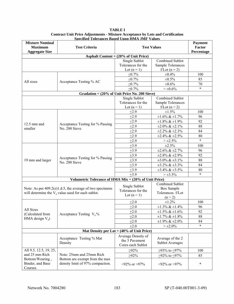
Network No. 7004280 183 SP (T-040.00T001-3-09)
TABLE I Contract Unit Price Adjustments - Mixture Acceptance by Lots and Certification
Specified Tolerances Based Upon HMA JMF Values Mixture Nominal
Maximum Aggregate Size
Test Criteria Test Values Payment Factor
Percentage Asphalt Content = (20% of Unit Price)
Single Sublot
Tolerances for the Lot (n = 1)
Combined Sublot Sample Tolerances
f/Lot (n = 2)
All sizes Acceptance Testing % AC
+0.7% ±0.4% 100 +0.7% ±0.5% 85 +0.7% ±0.6% 70 +0.7% > ±0.6% *
Gradation = (20% of Unit Price No. 200 Sieve)
Single Sublot
Tolerances for the Lot (n = 1)
Combined Sublot Sample Tolerances
f/Lot (n = 2)
12.5 mm and smaller
Acceptance Testing for % Passing No. 200 Sieve
+2.9 ±1.5% 100 +2.9 ±1.6% & ±1.7% 96 +2.9 ±1.8% & ±1.9% 92 +2.9 ±2.0% & ±2.1% 88 +2.9 ±2.2% & ±2.3% 84 +2.9 ±2.4% & ±2.5% 80 +2.9 > ±2.5% *
19 mm and larger Acceptance Testing for % Passing No. 200 Sieve
+3.9 ±2.5% 100 +3.9 ±2.6% & ±2.7% 96 +3.9 ±2.8% & ±2.9% 92 +3.9 ±3.0% & ±3.1% 88 +3.9 ±3.2% & ±3.3% 84 +3.9 ±3.4% & ±3.5% 80 +3.9 > ±3.5% *
Volumetric Tolerance of HMA Mix = (20% of Unit Price)
Note: As per 409.2(e)1.d.5, the average of two specimens will determine the Va value used for each sublot.
Single Sublot Tolerances for the
Lot (n = 1)
Combined Sublot Box Sample
Tolerances f/Lot (n = 2)
All Sizes (Calculated from HMA design Va)
Acceptance Testing Va %
+2.0 ±1.2% 100 +2.0 ±1.3% & ±1.4% 96 +2.0 ±1.5% & ±1.6% 92 +2.0 ±1.7% & ±1.8% 88 +2.0 ±1.9% & ±2.0% 84 +2.0 > ±2.0% *
Mat Density per Lot = (40% of Unit Price)
Acceptance Testing % Mat Density
Average Density of the 3 Pavement
Cores each Sublot
Average of the 2 Sublot Averages
All 9.5, 12.5, 19, 25, and 25 mm Rich Bottom/Wearing , Binder, and Base Courses
Note: 25mm and 25mm Rich Bottom are exempt from the max density limit of 97% compaction.
≥92% ≥93% to <97% 100 ≥92% >92% to <97% 85
<92% or >97% <92% or >97% *
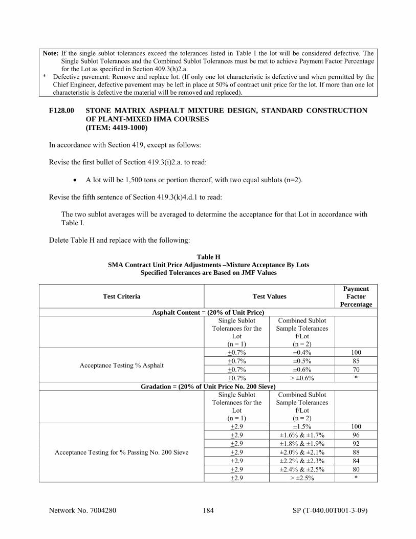
Network No. 7004280 184 SP (T-040.00T001-3-09)
Note: If the single sublot tolerances exceed the tolerances listed in Table I the lot will be considered defective. The Single Sublot Tolerances and the Combined Sublot Tolerances must be met to achieve Payment Factor Percentage for the Lot as specified in Section 409.3(h)2.a.
* Defective pavement: Remove and replace lot. (If only one lot characteristic is defective and when permitted by the Chief Engineer, defective pavement may be left in place at 50% of contract unit price for the lot. If more than one lot characteristic is defective the material will be removed and replaced).
F128.00 STONE MATRIX ASPHALT MIXTURE DESIGN, STANDARD CONSTRUCTION
OF PLANT-MIXED HMA COURSES (ITEM: 4419-1000) In accordance with Section 419, except as follows: Revise the first bullet of Section 419.3(i)2.a. to read:
A lot will be 1,500 tons or portion thereof, with two equal sublots (n=2). Revise the fifth sentence of Section 419.3(k)4.d.1 to read:
The two sublot averages will be averaged to determine the acceptance for that Lot in accordance with Table I.
Delete Table H and replace with the following:
Table H SMA Contract Unit Price Adjustments –Mixture Acceptance By Lots
Specified Tolerances are Based on JMF Values
Test Criteria Test Values Payment Factor
Percentage Asphalt Content = (20% of Unit Price)
Single Sublot Tolerances for the
Lot (n = 1)
Combined Sublot Sample Tolerances
f/Lot (n = 2)
Acceptance Testing % Asphalt
+0.7% ±0.4% 100 +0.7% ±0.5% 85 +0.7% ±0.6% 70 +0.7% > ±0.6% *
Gradation = (20% of Unit Price No. 200 Sieve)
Single Sublot Tolerances for the
Lot (n = 1)
Combined Sublot Sample Tolerances
f/Lot (n = 2)
Acceptance Testing for % Passing No. 200 Sieve
+2.9 ±1.5% 100 +2.9 ±1.6% & ±1.7% 96 +2.9 ±1.8% & ±1.9% 92 +2.9 ±2.0% & ±2.1% 88 +2.9 ±2.2% & ±2.3% 84 +2.9 ±2.4% & ±2.5% 80 +2.9 > ±2.5% *
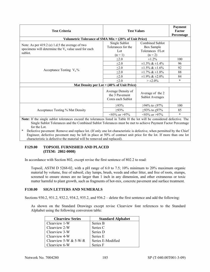
Network No. 7004280 185 SP (T-040.00T001-3-09)
Test Criteria Test Values Payment Factor
Percentage Volumetric Tolerance of SMA Mix = (20% of Unit Price)
Note: As per 419.2 (e) 1.d.5 the average of two specimens will determine the Va value used for each sublot.
Single Sublot Tolerances for the
Lot (n = 1)
Combined Sublot Box Sample
Tolerances f/Lot (n = 2)
Acceptance Testing Va %
+2.0 ±1.2% 100 +2.0 ±1.3% & ±1.4% 96 +2.0 ±1.5% & ±1.6% 92 +2.0 ±1.7% & ±1.8% 88 +2.0 ±1.9% & ±2.0% 84 +2.0 > ±2.0% *
Mat Density per Lot = (40% of Unit Price)
Average Density of
the 3 Pavement Cores each Sublot
Average of the 2 Sublot Averages
Acceptance Testing % Mat Density ≥93% ≥94% to <97% 100 ≥93% >93% to <97% 85
<93% or >97% <93% or >97% * Note: If the single sublot tolerances exceed the tolerances listed in Table H the lot will be considered defective. The
Single Sublot Tolerances and the Combined Sublot Tolerances must be met to achieve Payment Factor Percentage for the Lot.
* Defective pavement: Remove and replace lot. (If only one lot characteristic is defective, when permitted by the Chief Engineer, defective pavement may be left in place at 50% of contract unit price for the lot. If more than one lot characteristic is defective the material will be removed and replaced).
F129.00 TOPSOIL FURNISHED AND PLACED (ITEM: 2802-0008) In accordance with Section 802, except revise the first sentence of 802.2 to read:
Topsoil, ASTM D 5268-02, with a pH range of 6.0 to 7.5; 10% minimum to 20% maximum organic material by volume, free of subsoil, clay lumps, brush, weeds and other litter, and free of roots, stumps, screened to ensure stones are no larger than 1 inch in any dimension, and other extraneous or toxic matter harmful to plant growth, such as fragments of hot-mix, concrete pavement and surface treatment.
F130.00 SIGN LETTERS AND NUMERALS Sections 930.2, 931.2, 932.2, 934.2, 935.2, and 936.2 – delete the first sentence and add the following:
As shown on the Standard Drawings except revise Clearview font references to the Standard Alphabet using the following conversion table:
Clearview Series Standard Alphabet
Clearview 1-W Clearview 2-W Clearview 3-W Clearview 4-W Clearview 5-W & 5-W-R Clearview 6-W
Series B Series C Series D Series E Series E-Modified Series F
Network No. 7004280 186 SP (T-040.00T001-3-09)
Sheets 2 of 12 through 5 of 12 in TC-8700C are no longer applicable. F131.00 IMPERVIOUS MATERIAL (ITEM: 4000-8001) F131.01 Description - This work is the construction of a compacted impervious material layer within
the wetland mitigation site using suitable material approved by the Representative. F131.02 Material - Soil - Perform acceptance testing of material at the source. Obtain verification
samples at the job site after the material has been spread in place but before compaction. Provide material which meets the following physical characteristics, unless approved otherwise by the Representative.
Gradation - 95% passing one-inch sieve, more than 35% passing No. 200 sieve. Minimum Dry Weight Density - 95 pounds per cubic foot determined in accordance with PTM No. 106, Method B. Maximum Liquid Limit - 65, determined in accordance with AASHTO-T89. Plasticity Index - Not less than Liquid Limit minus 30, determined in accordance with AASHTO-T90 for soils with liquid limits of 41 to 65. Minimum Compaction - 95% of the determined dry weight density. If the physical characteristics of the material fail to meet these requirements, over-excavate the area and replace the soil with an appropriate substitute which does meet the minimum requirements.
F131.03 Construction -
(a) Equipment.
1. Spreading. Approved Grader or Spreader capable of spreading material in a uniform layer as indicated or directed.
2. Compaction Equipment. Section 108.05(c)3.
(b) General. Prepare subgrade prior to placing impervious material.
Do not place impervious material on soft, muddy, or frozen areas. Before placing, satisfactorily correct irregularities or soft areas in the prepared areas.
(c) Placement. Deposit the material on the prepared subgrade with approved spreading
equipment. Construct the impervious material layer in courses not over 8 inches in compacted depth. Construct the required impervious material before constructing associated topsoil layers. To reduce rutting and damage to the impervious material, avoid using impervious material areas as haul roads.
(d) Compaction and Density. Compact each layer for its full width to not less than 95% of
the determined dry weight density. In-place density or compaction will be determined in
Network No. 7004280 187 SP (T-040.00T001-3-09)
accordance with PTM No. 112 or PTM No. 402. At the time of compaction, maintain the soil moisture content to within 2 percentage points of the optimal soil moisture content for that material. Proceed with compaction gradually from sides to center, with each succeeding pass uniformly overlapping the previous pass. Continue until the entire area is satisfactorily shaped and compacted.
If the impervious material does not contain sufficient moisture after placement, add water to obtain proper compaction. Otherwise, remix, reconstruct, or replace the material as directed.
(e) Surface Tolerance.
Mitigation Area - It is the intention of mitigation area to assimilate a naturally occurring ecosystem; therefore, tolerance will be the most important function of the hydraulic design requirements. Provide that water surface elevations and locations are within 2 inches vertically and 6 inches horizontally as indicated.
(f) Test for Depth. Section 350.3(g).
F131.04 Measurement and Payment - Cubic Yard. Includes stockpiling of impervious material.
The impervious material will not be paid for complete in-place until the topsoil backfill or final surface is constructed. However, payment may be made to 75% of the quantity of the impervious material on the current estimates, in advance of the succeeding operation, provided that the impervious material has been satisfactorily completed and maintained pending placement of the topsoil material.
F132.00 SUBSOIL COMPACTION (ITEMS: 4000-8002, 2203-0003, AND 4000-8001) F132.01 Description - This work is the construction of a compacted subsoil layer within the wetland
mitigation site. This site had a previous agricultural use. While drain tiles were not encountered during the preliminary investigation of the site, their absence has not been confirmed. If encountered during excavation and or subgrade preparation, drain tiles are to be removed.
F132.02 Material -
(a) Soil - Ensure that the existing subsoil material meets the following physical characteristics, unless approved otherwise by the Representative.
Gradation - 95% passing one-inch sieve, more than 20% passing No. 200 sieve. Minimum Dry Weight Density - 95 pounds per cubic foot determined in accordance with PTM No. 106, Method B. Maximum Liquid Limit - 65, determined in accordance with AASHTO-T89. Plasticity Index - Not less than Liquid Limit minus 30, determined in accordance with AASHTO-T90 for soils with liquid limits of 41 to 65. Minimum Compaction - 95% of the determined dry weight density.
(b) Impervious Material - Special Provision F131.02.

Network No. 7004280 188 SP (T-040.00T001-3-09)
F132.03 Construction -
(a) Equipment.
1. Compaction Equipment. Section 108.05(c)3.
(b) General. Prepare subgrade prior to compacting the subsoil material.
Do not compact subsoil material that is soft, muddy, or frozen. Before commencing compaction, satisfactorily correct irregularities or soft areas in the prepared areas. If the physical characteristics of the soil fail to meet the specifications, over-excavate the area to a depth of one foot and replace the unsuitable material with Impervious Material in accordance with Special Provision F131.03.
(c) Compaction and Density. Compact the subsoil material to not less than 95% of the
determined dry weight density. In-place density or compaction will be determined in accordance with PTM No. 112 or PTM No. 402. At the time of compaction, maintain the soil moisture content to within ±2 percentage points of the optimal soil moisture content for that material. Proceed with compaction gradually from sides to center with each succeeding pass uniformly overlapping the previous pass. Continue until the entire area is satisfactorily shaped and compacted.
If the subsoil material does not contain sufficient moisture, add water to obtain proper compaction.
(d) Surface Tolerance.
1. Mitigation Area - It is the intention of mitigation area to assimilate a naturally
occurring ecosystem; therefore, tolerance will be the most important function of the hydraulic design requirements. Provide that water surface elevations and locations are within 2 inches vertically and 6 inches horizontally as indicated.
(e) Test for Depth. Section 350.3(g). (f) Drainage Tile Removal and Sealing
1. Remove drain tile within the excavation area. 2. Seal remaining downstream pipe openings. All below grade pipe to be abandoned
shall be sealed with grout, Class “C” concrete or brick and mortar. The grout, concrete, or brick and mortar shall extend into the pipe for at least 12 inches forming a solid water proof plug completely bonded to the pipe.
F132.04 Measurement and Payment -
(a) Subsoil compaction, testing, and surface tolerance -Square Yard. Drain tile removal and sealing are incidental to subsoil compaction.
(b) Class 1A Excavation – Cubic Yard (for removal of unsuitable material) (c) Impervious Material – Cubic Yard (for replacement of subgrade material)

Network No. 7004280 189 SP (T-040.00T001-3-09)
F133.00 RESIDUAL WASTE REMOVAL (ITEM: 4000-8003) F133.01 Description - This work is the removal and disposal of residual waste excavated during
construction. For the purpose of this specification, residual waste is defined as:
Waste resulting from industrial operations that is not classified as a hazardous waste. Residual waste in Pennsylvania is addressed under Title 25, Chapters 287 through 299 Residual Waste Management.
The Contractor may encounter glass, concrete block and wire in the area delineated on the plan drawings. This area corresponds to test pits excavated during preliminary investigation of the site.
F133.02 Material -
Waste Containers: Provide DOT-approved containers of the appropriate size and type for the hazardous waste generated on the project. Use containers that are resistant to rust and corrosion (painted, if constructed of steel), that have tight-fitting lids or covers, and which are water resistant and leak proof.
F133.03 Construction -
(a) Conduct the work in strict accordance with federal, state, and local regulations governing the collection, handling, transportation, and disposal of waste.
(b) Comply with Pennsylvania Title 25, Chapters 285 and 299 for the handling, packaging, and storage of residual and municipal construction non-hazardous waste. Comply with additional county and city regulations as applicable.
(c) Collect and store the waste at the end of each working day in storage drums or containers such that no waste is left exposed overnight, at a minimum. Use DOT-approved containers for hazardous and residual waste storage.
(d) Verify that all waste (hazardous, residual, and non-hazardous) is transported to the appropriate recycling or disposal facility within 90 days after waste is first placed into the container.
(e) Do not fill any container or roll-off in excess of the capacity marked on the container. If delays during pick-up are caused by overfilled containers, remediate the situation at no additional cost to the Commission.
(f) Waste Transportation and Disposal.
1. Transport and dispose of all residual and non-hazardous municipal construction waste in accordance with Pennsylvania Title 25, Chapters 271, 273, 279, 285, and 299.
2. Verify that waste is completely covered during transport. 3. Verify that the truck is properly designated with a residual waste sign measuring 6
inches in height when transporting residual waste. 4. Verify that the transportation vehicle has a Pollution Prevention and Contingency
Plan and carries the following information: county and state where waste originated, name and address of the carrier, name and location of disposal facility, and fire extinguisher.
5. Comply with additional county and city regulations as applicable. F133.04 Measurement and Payment – Ton.
Network No. 7004280 190 SP (T-040.00T001-3-09)
F134.00 HABITAT ENHANCEMENT - BLUEBIRD NEST BOX ASSEMBLAGE (ITEM: 4000-8011) F134.01 Description - This work is the construction and placement of bluebird nesting boxes within
the wetland mitigation area, as shown on the plan. F134.02 Material - Constructed of new materials, free of cracks and defects. Do not use plywood.
(a) 1-inch x 6-inch Pressure Treated Pine or Cedar – Section 1031.02(a). (b) 1-3/4 inch galvanized nails – ASTM F1667. (c) 1-3/4 inch galvanized screw nails or (pivot nails) – ASTM F1667. (d) Double headed nail for holding door closed – ASTM F1667. (e) 4-inch x 4-inch pressure treated post. (f) 4-inch galvanized wood screws.
F134.03 Construction -
(a) Construct nest box as detailed to allow 1/4 inch ventilation space between sides and top. (b) Cut circular entrance 1-1/2 inches in diameter, 1-3/8 inches from top of front. (c) Cut 3/8 inch off each corner of bottom as indicated. (d) Locate pivot nails exactly opposite each other as shown for proper opening of sideboard. (e) Mount, where indicated, on the east side of a 10-foot 4-inch by 4-inch post that is sunk at
least 2-feet vertically into the substrate to support the nest box. (f) Orient front of nest box as shown on plans.
F134.04 Measurement and Payment – Each. F135.00 TREE PROTECTION (ITEM: 4000-8012) F135.01 Description - This work is the furnishing, installation, and maintenance of deer protection
fence for planted trees. F135.02 Material -
(a) Fence. 6-inch x 6-inch PVC mesh fence, 6 feet high. Black or dark green in color. (b) Posts. 2-inch x 2-inch hardwood post a minimum of 8.0 feet in length. Manufactured
from hardwood and free of knots. (c) Connectors. Vinyl coated twist ties or as directed.
F135.03 Construction - Drive posts a minimum of 2 feet below finish grade. Trench 2 inches below
finished grade prior to erecting fence. Provide a square enclosure with a minimum side length of 6 feet. Install fence in trench. Secure fence to posts and secure seam with connectors at one foot spacing. Provide 1-foot minimum overlap of fence.
Unless otherwise directed, maintain the enclosures for a period of two years after installation. F135.04 Measurement and Payment - Each.
Network No. 7004280 191 SP (T-040.00T001-3-09)
F136.00 HERBICIDE APPLICATION (ITEM: 4000-8022) F136.01 Description - This work includes the application of herbicide to selected areas within the
approximately 1.0 acre wetland mitigation site to control invasive species as described in the Wetland Mitigation Plan and subsequent Post-Construction Monitoring Reports.
F136.02 Material - Herbicide and appropriate surfactant - Conforming to all applicable federal and
state pesticide acts and registration requirements, and as specified in PCID No. 1094 – Herbicides (Weed and Brush Control) issued by the Pennsylvania Department of General Services, Bureau of Purchases, Quality Assurance Division, for the appropriate type.
Furnish herbicide in manufacturer's labeled container, as follows:
In Seeded and Planted Areas. N-(phosphonomethyl) glycine, (commonly referred as "glyphosate").
F136.03 Construction -
(a) Utilize Backpack Spray Method for the application of herbicide with concentration and rate as recommended by the herbicide manufacturer for the target species.
(b) The firm performing the herbicide application shall hold a Pesticide Business License
with the Pennsylvania Department of Agriculture Bureau of Plant Industry. The herbicide applicator must be properly licensed as a Commercial Pesticide Applicator with a Category 10-Right of Way Certification.
(c) Apply herbicide to broad-leaved weeds and plants considered noxious or invasive species
throughout the mitigation site as directed. Herbicide applications shall be carefully applied to the specific areas of the mitigation sites limit of disturbance areas. Any trees, shrubs and riparian buffer plants previously planted are not intended to be sprayed or become in contact with herbicide. Apply N-(phosphonomethyl) glycince, more commonly referred to as “glyphosate” at the rate as per manufacturer recommendations.
(d) Do not apply herbicide if rain is forecasted within 24 hours or as per manufacturer
recommendations. (e) Removing Target Plants - Do not prune, trim, or remove any sprayed plants for a period
of at least 15 days or as recommended by the manufacturer. Remove only targeted plants which are dead. No other plant is to be removed, pruned, or trimmed unless otherwise indicated, directed, or required for the planting of trees and shrubs. Apply a second round to plants not killed at no cost to the Commission.
(f) Applications Rounds - Apply herbicide to broad leaf weeds/noxious and plants
considered invasive species as follows.
1. 60 days after grading/seeding has taken place. 2. 15 days before planting trees and shrubs, as directed by the representative. 3. During Trees and Shrubs Period of Establishment, 30 days after planting trees and
shrubs as directed by the representative. 4. Annually subsequent to the post construction monitoring report and a directed by the
representative.
Network No. 7004280 192 SP (T-040.00T001-3-09)
F136.04 Measurement and Payment – Gallons F137.00 TOPSOIL REMOVAL AND STOCKPILING (ITEM: 4205-0150) F137.01 Description - This work is the removal of topsoil from the affected areas and stockpiling said
topsoil material within the proposed mitigation site as indicated. F137.02 Material - Salvaged Topsoil - Upper soil horizon within the indicated limit of work including
all natural vegetative material. Provide that the salvaged soil is reasonably free of stones larger than 2 inches and other objectionable foreign material.
F137.03 Construction -
(a) Salvage Topsoil. Clear and grub the affected areas of woody vegetation in order to not disturb the soil profile. Chip woody vegetation above the ground line, in-place to a general maximum size of 2 inches by 6 inches and evenly distribute over the ground surface. Remove the upper soil horizon to the depth shown on the plan and cross sections. Adjust equipment and methods of operation to avoid mixing subsoil with topsoil.
(b) Stockpiling Topsoil. Provide that salvaged topsoil is not stockpiled for a period greater
than 6 months unless otherwise approved by the Representative. During the period of stockpiling, keep the soil damp but not saturated. Watering of stockpiles as directed will be incidental to this pay item.
F137.04 Measurement and Payment - Cubic Yard. F138.00 WET MIX 1 AND WET MIX 2 (ITEMS: 4804-0001 and 4804-0002) F138.01 Description - This work is furnishing and placing of the wetland seed of the type and quantity
specified on the plan drawings and soil supplements. F138.02 Material - Seed Mixture.
(a) Soil Supplements. Section 804.2(a). (b) Wetland Seed. Fresh, clean new crop seed of the required varieties supplied in sealed
containers with the suppliers guaranteed analysis of the contents including weight, variety, and minimum PLS (pure live seed). PLS is the percent purity multiplied by the percent germination of the seed.
Furnish seed labeled in accordance with the Pennsylvania Seed Act and Pennsylvania Code, Chapter III Seed Testing, Labeling, and Standards. Seed which has become wet, moldy, or otherwise damaged will not be accepted. If seeds are not premixed to the required formula by one seed supplier, carefully weigh and mix the wetland seed by an approved method in the amounts shown in the seed formula. If the seed is mixed by a dealer, furnish the Commission with the dealer’s guaranteed statement of composition of the mixture and percentage of the purity and germination of each variety. Sow no seed until the certificates have been submitted and seed tests have been approved.
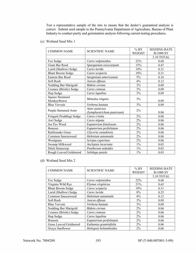
Network No. 7004280 193 SP (T-040.00T001-3-09)
Test a representative sample of the mix to ensure that the dealer’s guaranteed analysis is correct. Submit seed sample to the Pennsylvania Department of Agriculture, Bureau of Plant Industry to conduct purity and germination analysis following current testing procedures.
(c) Wetland Seed Mix 1
COMMON NAME SCIENTIFIC NAME % BY
WEIGHT SEEDING RATE
lb/1000 SY 3.10 TOTAL
Fox Sedge Carex vulpinoidea 22% 0.68 Giant Bur Reed Sparganium eurycarpum 15% 0.47 Lurid (Shallow) Sedge Carex lurida 10% 0.31 Blunt Broom Sedge Carex scoparia 10% 0.31 Eastern Bur Reed Sarganium americanum 5% 0.16 Soft Rush Juncus effusus 4% 0.12 Nodding Bur Marigold Bidens cernua 3% 0.09 Cosmos (Bristly) Sedge Carex comosa 3% 0.09 Hop Sedge Carex lupulina 3% 0.09 Square Stemmed Monkeyflower
Mimulus ringens 3% 0.09
Blue Vervain Verbena hastata 3% 0.09
Purple Stemmed Aster Aster puniceus (Symphyotrichum puniceum)
2% 0.06
Fringed (Nodding) Sedge Carex crinita 2% 0.06 Awl Sedge Carex stipata 2% 0.06 Joe Pye Weed Eupatorium fistulosum 2% 0.06 Boneset Eupatorium perfoliatum 2% 0.06 Rattlesnake Grass Glyceria canadensis 2% 0.06 Common Sneezeweed Helenium autumnale 2% 0.06 Woolgrass Scirpus cyperinus 2% 0.06 Swamp Milkweed Asclepias incarnata 1% 0.03 Ditch Stonecrop Penthorum sedoides 1% 0.03 Rough Leaved Goldenrod Solidago patula 1% 0.03
(d) Wetland Seed Mix 2
COMMON NAME SCIENTIFIC NAME % BY
WEIGHT SEEDING RATE
lb/1000 SY 3.10 TOTAL
Fox Sedge Carex vulpinoidea 22% 0.68 Virginia Wild Rye Elymus virginicus 21% 0.65 Blunt Broom Sedge Carex scoparia 10% 0.31 Lurid (Shallow) Sedge Carex lurida 8% 0.25 Common Sneezeweed Helenium autumnale 4% 0.12 Soft Rush Juncus effusus 3% 0.09 Blue Vervain Verbena hastata 3% 0.09 Nodding Bur Marigold Bidens cernua 2% 0.06 Cosmos (Bristly) Sedge Carex comosa 2% 0.06 Hop Sedge Carex lupulina 2% 0.06 Boneset Eupatorium perfoliatum 2% 0.06 Grass Leaved Goldenrod Euthamia graminifolia 2% 0.06 Oxeye Sunflower Heliopsis helianthoides 2% 0.06

Network No. 7004280 194 SP (T-040.00T001-3-09)
COMMON NAME SCIENTIFIC NAME % BY
WEIGHT SEEDING RATE
lb/1000 SY Square Stemmed Monkeyflower
Mimulus ringens 2% 0.06
Swamp Milkweed Asclepias incarnata 1% 0.03
Zigzag Aster Aster prenanthoides (Symphyotrichum p.)
1% 0.03
Purple Stemmed Aster Aster puniceus (Symphyotrichum puniceum)
1% 0.03
Flat Topped White Aster Aster umbellatus (Doellingeria umbellata)
1% 0.03
Awl Sedge Carex stipata 1% 0.03 Joe Pye Weed Eupatorium fistulosum 1% 0.03 Rough Avens Geum laciniatum 1% 0.03 Rattlesnake Grass Glyceria canadensis 1% 0.03 American Mannagrass Glyceria grandis 1% 0.03 Path Rush Juncus tenuis 1% 0.03 Seedbox Ludwigia alternifolia 1% 0.03 Sensitive Fern Onoclea sensibilis 1% 0.03 Many Leaved Bulrush Scirpus polyphyllus 1% 0.03
Giant Ironweed Vernonia gigantea (V. altissima)
1% 0.03
Golden Alexanders Zizia aurea 1% 0.03 F138.03 Construction
(a) General. Spread seed at the rate specified and between March 15 and May 30 or as otherwise indicated.
Many areas indicated on the plans are of irregular, freeform configurations. These configurations convey the concept of seeding in naturalistic, non-geometric beds. Perform seeding operations within ±2 feet of these configurations. Stake out the general area configuration to guide the seed application.
(b) Soil Preparation.
1. Bare Soil. Thoroughly loosen the surface to a depth of at least 2 inches by disking,
harrowing, or by other acceptable methods until tillage is satisfactory. Remove all weed and grass growth in the area to be seeded.
2. Previously Seeded Areas. Kill all designated grass surface areas with an approved
non-selective herbicide, Type XVI as listed in Specification H-18 of the Department of General Services.
After vegetation has died, mow closely to a height not exceeding one inch. Collect and dispose of the clippings.
(c) Soil Supplements – test a representative soil sample to determine the application rates for
Pulverized Agriculture Limestone and 10-20-20 Fertilizer. (d) Seeding. Sow seeds uniformly on the prepared areas using an over-seeding method of
slicing or slitting rows through the soil, dropping seeds, and covering/compacting seeds
Network No. 7004280 195 SP (T-040.00T001-3-09)
in place. Accomplish this in one operation. Provide that the depth of soil over seed does not exceed ¼ inch. Row spacing should not exceed 8 inches.
1. Inspect seeding equipment and adjust, if required, to assure the specified rate of
application. 2. Sow seeds in two directions (perpendicular to each other) for better coverage. 3. Clear, dry masonry sand can be added to the seed mixture at a ratio of 4 sand to 1
seed to help facilitate seed application.
(e) Mulch. Section 805 and as follows: Place mulching in a separate operation within 48 hours after the wetland seeding.
(f) Maintenance. Satisfactorily maintain wetland seeding areas until entire project has been
completed. Do not mow wetland seed areas.
1. Control prohibited and noxious weed growth. F138.04 Measurement and Payment
(a) Seeding and Soil Supplements – Pound. Measured by the number of pounds of seed actually incorporated into the work for the seed formula and soil supplement applications specified in this specification. Includes payment for any herbicide applications, mowing, disking, harrowing, dragging, dozer tracking or any other required surface preparation. No additional payment will be made for reseeding and reapplying soil supplements to areas exhibiting less than 70% growth as specified in Section 804.3(i). The Commission will pay for reseeding and reapplying soil supplements on failed slope areas, as specified in Section 804.3(j), at the contract unit price, in addition to the original accepted application of seeding and soil supplements.
F139.00 UPL MIX 1 AND UPL MIX 2 (ITEMS: 4804-0003 AND 4804-0004) F139.01 Description - This work is the furnishing and placing of groundcover seed and soil
supplements within the restoration area. F139.02 Material -
(a) Soil Supplements - Section 804.2(a). (b) Upland Seed. Fresh, clean new crop seed of the required varieties supplied in sealed
containers with the suppliers guaranteed analysis of the contents including weight, variety, and minimum PLS (pure live seed). PLS is the percent purity multiplied by the percent germination of the seed.
Furnish seed labeled in accordance with the Pennsylvania Seed Act and Pennsylvania Code, Chapter III Seed Testing, Labeling, and Standards. Seed which has become wet, moldy, or otherwise damaged will not be accepted. If seeds are not premixed to the required formula by one seed supplier, carefully weigh and mix the wetland seed by an approved method in the amounts shown in the seed formula. If the seed is mixed by a dealer, furnish the Commission with the dealer’s guaranteed statement of composition of the mixture and percentage of the purity and
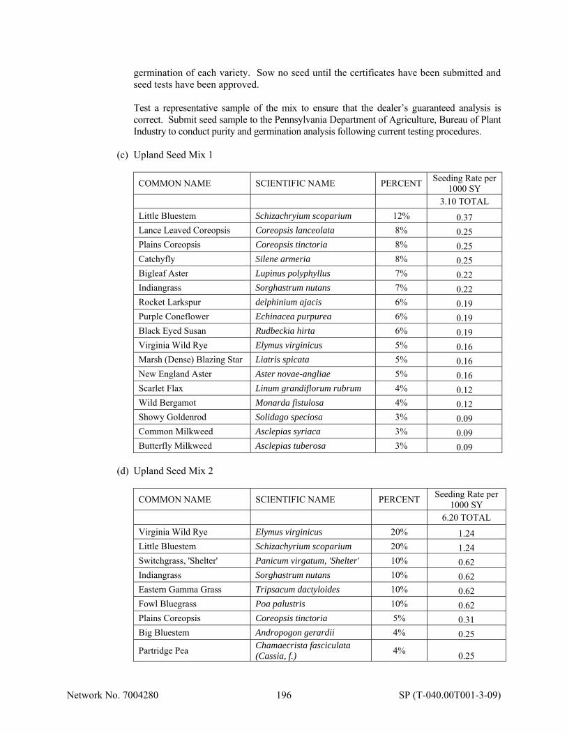
Network No. 7004280 196 SP (T-040.00T001-3-09)
germination of each variety. Sow no seed until the certificates have been submitted and seed tests have been approved. Test a representative sample of the mix to ensure that the dealer’s guaranteed analysis is correct. Submit seed sample to the Pennsylvania Department of Agriculture, Bureau of Plant Industry to conduct purity and germination analysis following current testing procedures.
(c) Upland Seed Mix 1
COMMON NAME SCIENTIFIC NAME PERCENT Seeding Rate per
1000 SY 3.10 TOTAL
Little Bluestem Schizachryium scoparium 12% 0.37 Lance Leaved Coreopsis Coreopsis lanceolata 8% 0.25 Plains Coreopsis Coreopsis tinctoria 8% 0.25 Catchyfly Silene armeria 8% 0.25 Bigleaf Aster Lupinus polyphyllus 7% 0.22 Indiangrass Sorghastrum nutans 7% 0.22 Rocket Larkspur delphinium ajacis 6% 0.19 Purple Coneflower Echinacea purpurea 6% 0.19 Black Eyed Susan Rudbeckia hirta 6% 0.19 Virginia Wild Rye Elymus virginicus 5% 0.16 Marsh (Dense) Blazing Star Liatris spicata 5% 0.16 New England Aster Aster novae-angliae 5% 0.16 Scarlet Flax Linum grandiflorum rubrum 4% 0.12 Wild Bergamot Monarda fistulosa 4% 0.12 Showy Goldenrod Solidago speciosa 3% 0.09 Common Milkweed Asclepias syriaca 3% 0.09 Butterfly Milkweed Asclepias tuberosa 3% 0.09
(d) Upland Seed Mix 2
COMMON NAME SCIENTIFIC NAME PERCENT Seeding Rate per
1000 SY 6.20 TOTAL
Virginia Wild Rye Elymus virginicus 20% 1.24 Little Bluestem Schizachyrium scoparium 20% 1.24 Switchgrass, 'Shelter' Panicum virgatum, 'Shelter' 10% 0.62 Indiangrass Sorghastrum nutans 10% 0.62 Eastern Gamma Grass Tripsacum dactyloides 10% 0.62 Fowl Bluegrass Poa palustris 10% 0.62 Plains Coreopsis Coreopsis tinctoria 5% 0.31 Big Bluestem Andropogon gerardii 4% 0.25
Partridge Pea Chamaecrista fasciculata (Cassia, f.)
4% 0.25
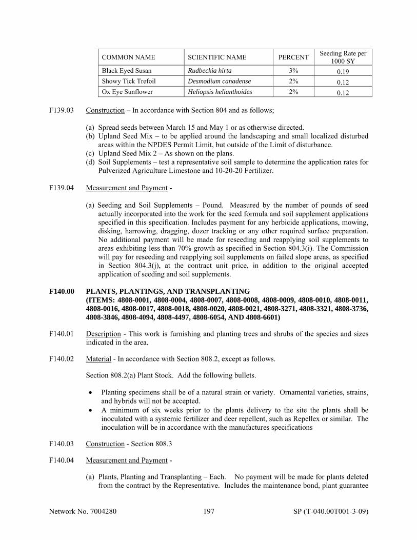
Network No. 7004280 197 SP (T-040.00T001-3-09)
COMMON NAME SCIENTIFIC NAME PERCENT Seeding Rate per
1000 SY Black Eyed Susan Rudbeckia hirta 3% 0.19 Showy Tick Trefoil Desmodium canadense 2% 0.12 Ox Eye Sunflower Heliopsis helianthoides 2% 0.12
F139.03 Construction – In accordance with Section 804 and as follows;
(a) Spread seeds between March 15 and May 1 or as otherwise directed. (b) Upland Seed Mix – to be applied around the landscaping and small localized disturbed
areas within the NPDES Permit Limit, but outside of the Limit of disturbance. (c) Upland Seed Mix 2 – As shown on the plans. (d) Soil Supplements – test a representative soil sample to determine the application rates for
Pulverized Agriculture Limestone and 10-20-20 Fertilizer. F139.04 Measurement and Payment -
(a) Seeding and Soil Supplements – Pound. Measured by the number of pounds of seed actually incorporated into the work for the seed formula and soil supplement applications specified in this specification. Includes payment for any herbicide applications, mowing, disking, harrowing, dragging, dozer tracking or any other required surface preparation. No additional payment will be made for reseeding and reapplying soil supplements to areas exhibiting less than 70% growth as specified in Section 804.3(i). The Commission will pay for reseeding and reapplying soil supplements on failed slope areas, as specified in Section 804.3(j), at the contract unit price, in addition to the original accepted application of seeding and soil supplements.
F140.00 PLANTS, PLANTINGS, AND TRANSPLANTING (ITEMS: 4808-0001, 4808-0004, 4808-0007, 4808-0008, 4808-0009, 4808-0010, 4808-0011,
4808-0016, 4808-0017, 4808-0018, 4808-0020, 4808-0021, 4808-3271, 4808-3321, 4808-3736, 4808-3846, 4808-4094, 4808-4497, 4808-6054, AND 4808-6601)
F140.01 Description - This work is furnishing and planting trees and shrubs of the species and sizes
indicated in the area. F140.02 Material - In accordance with Section 808.2, except as follows. Section 808.2(a) Plant Stock. Add the following bullets.
Planting specimens shall be of a natural strain or variety. Ornamental varieties, strains, and hybrids will not be accepted.
A minimum of six weeks prior to the plants delivery to the site the plants shall be inoculated with a systemic fertilizer and deer repellent, such as Repellex or similar. The inoculation will be in accordance with the manufactures specifications
F140.03 Construction - Section 808.3 F140.04 Measurement and Payment -
(a) Plants, Planting and Transplanting – Each. No payment will be made for plants deleted from the contract by the Representative. Includes the maintenance bond, plant guarantee

Network No. 7004280 198 SP (T-040.00T001-3-09)
and replacement, watering, fertilizing and the application of the antidessicant/antitranspirant product.
F141.00 AS-CONSTRUCTED SURVEY (ITEM: 4000-8010) F141.01 Description - This work is the development of as-constructed drawings of the entire wetland
mitigation site upon completion of the earthwork but before planting. This work includes the plotted survey and the submission of contour plans to the Commission representative for submittal to the environmental agencies for approval as required by the United States Army Corps of Engineers permit. Submit the plans to the representative no more than 60 days after completion of earthwork.
F141.03 Construction – Furnish as-constructed topographic plan at 1 inch = 50 feet scale and with a
one-foot contour interval for the following baseline.
(a) 00+00 – 07+00 - Wetland Mitigation.
Upon the completion of subsoil compaction and prior to placement of the topsoil, survey spot elevations at 25 foot intervals to document the finished subgrade elevations. Document the survey on the project cross sections to ensure that the subgrade has been constructed to plan elevations. Provide spot elevations of final grades at 25-foot intervals within the site boundaries. This work is to be completed by a licensed surveyor in the Commonwealth of Pennsylvania who signs and seals final plans. Obtain written approval of the as-constructed topographic survey from the Commission representative prior to permanent planting. Allow 30 days for review and approval of the as-constructed topographic survey plans by the environmental agencies.
F141.04 Measurement and Payment - Lump Sum. F142.00 WOODEN MATTING (ITEM: 4806-0009) F142.01 Description - This work consists of installing wood mats to protect soils in the vicinity of
wetland construction as depicted on the plan drawings. F142.02 Material - As indicated and as follows.
(a) Geotextile, Class 2, Type B - Section 735 (b) Wood Members - 4” (min) x 4” (min) x 10’ (min) Rough Cut Oak (or approved equal)
Timber. Longer or larger members may be needed to distribute the weight better on very weak soils or under heavy loads.
(c) 3/16” Galvanized Steel Cable Clamps (d) 3/16” Galvanized Steel Cable (e) Seeding and Soil Supplements - Special Provisions F138.02 and F139.02 (f) Mulching - Section 805.2
F142.03 Construction - As shown and as follows:
Network No. 7004280 199 SP (T-040.00T001-3-09)
Prior to disturbing wetlands, place Geotextile over the area to receive the Wooden Matting. Assemble the wood members and cables as indicated. During installation, tuck ends of all cable loops under the mats to avoid snagging by passing equipment. When no longer needed, disassemble and remove the wooden matting for use in other areas (if needed) and satisfactorily restore the area to preconstruction conditions. Seed all areas disturbed by this work using WET MIX 2 or UPL MIX 2.
F142.04 Measurement and Payment – Lump Sum. F143.00 LIVE STAKES (ITEM: 4808-0022) F143.01 Description - This work is the furnishing and placing of live cuttings, of the type specified, as
indicated on the mitigation plans. F143.02 Material -
(a) Willow Cuttings - Must be alive, with side branches cleanly removed, and bark intact. The larger or thicker butt ends should be cleanly cut at a 45-degree angle, for easy insertion into the soil. The top should be cut square or blunt. Cuttings should have at least 2 bud scars near the top to facilitate the development of branches. Cuttings must be fresh and kept moist. After they have been prepared into appropriate lengths, do not store for more than 1 day before tamping into the soil. To increase survival rate, place the cuttings the same day that they are prepared.
(b) Use live Black Willow (Salix nigra) cuttings that are a minimum of 1-1/2 inches in
diameter and a minimum of 3 feet long: F143.03 Construction - Use an iron bar or a similar device with a diameter of 1-1/2 inches to puncture
the ground to form a pilot hole in the embankment of the mitigation areas. Tamp the live willow cuttings into the embankment with a dead-blow hammer (hammer with a hollow head, filled with shot). Do not split the live willow cuttings during tamping. Insert at right angles to the slope with only 8 inches extending above the newly graded ground. Ensure that the base of the live willow cutting is firmly in contact with the soil. Replace any live willow cuttings that were split during tamping.
Place the live willow cuttings during the dormant season from November through March. Follow Section 808.3(g)6 for period of establishment. F143.04 Measurement and Payment - Each. F144.00 PRIVATE UTILITY LINE REMOVAL (ITEM: 4000-8004) F144.01 Description - This work entails removing utility poles and associated overhead wire for de-
energized service lines. Contractor will coordinate with applicable utilities (Verizon, Comcast, and Duquesne Power) regarding private line status and for the work around the connection point within the state right-of-way. All removal, salvage, and disposal are included in the price for this item. Utility poles are classified as residual waste under Title 25, Chapters 287 through 299 Residual Waste Management.
Network No. 7004280 200 SP (T-040.00T001-3-09)
F144.03 Construction -
(a) Conduct the work in strict accordance with federal, state, and local regulations governing the collection, handling, transportation, and disposal of demolition/construction waste.
(b) Comply with Pennsylvania Title 25, Chapters 285 and 299 for the handling, packaging, and storage of residual and municipal construction non-hazardous waste. Comply with additional County and City regulations as applicable.
(c) Remove utility pole and associated wiring from service line traverse site. Completely extract poles in their entirety if practicable. Poles may be cut at their base if complete extraction is not possible. Saw cut pole at the base 6 inches below grade. Cut poles in 8 feet sections or smaller to facilitate transport and disposal. Spool wires for recycling.
(d) Backfill any excavation resulting from the pole extraction. Obtain backfill from suitable source material onsite. Compact material placed in hole/excavated area as specified under Section 601.3(f) or Section 206.3(b)1
(e) Collect and store demolition waste at the end of each working day in a manner that no waste is left exposed overnight, at a minimum. Use DOT-approved containers for hazardous and residual waste storage.
(f) Transport all demolition waste (hazardous, residual, and non-hazardous) to the appropriate recycling or disposal facility within 14 days after demolition.
(g) Do not fill any container or roll-off in excess of the capacity marked on the container. If delays during pickup are caused by overfilled containers, remediate the situation at no additional cost to the Commission.
(h) Waste Transportation and Disposal.
1. Transport and dispose of all residual and non-hazardous municipal construction waste in accordance with Pennsylvania Title 25, Chapters 271, 273, 279, 285, and 299.
2. Verify that waste is completely covered during transport. 3. Verify that the truck is properly designated with a residual waste sign measuring 6
inches in height when transporting residual waste. 4. Verify that the transportation vehicle has a Pollution Prevention and Contingency Plan
and carries the following information: county and state where waste originated, name and address of the carrier, name and location of disposal facility, and fire extinguisher.
5. Comply with additional county and city regulations as applicable. F144.04 Measurement and Payment - Lump Sum. F145.00 PLACING STOCKPILED TOPSOIL MIXTURE (ITEM: 4803-0002) F145.01 Description - This work is placing of stockpiled topsoil mixture within the constructed
wetlands and project area. F145.02 Material - Section 801.2 F145.03 Construction - In accordance with Section 803 except replace Section 803.3(b) with the
following:
Dewater the area to be backfilled with topsoil using a method approved by the Representative. The standing water elevation must be reduced to an elevation below the lowest elevation of the topsoil to be placed (this may require some basins to be completely dewatered). Loosen soil above the elevation of the dewatered pool to a depth of 2 inches.
Network No. 7004280 201 SP (T-040.00T001-3-09)
Place stockpiled topsoil mixture on the prepared area to obtain final grade elevation as indicated. Use equipment with a maximum ground bearing pressure of 5 psi to minimize over-compaction. Perform additional earth modification activities as directed to correct over-compaction at no extra cost. The final grade surface elevation tolerance is within 6 inches vertically and 6 inches horizontally as indicated.
F145.04 Measurement and Payment - Cubic Yard. F146.00 BY-PASS PUMP SYSTEM WITH COFFERDAM (ITEM: 4806-0002) F146.01 Description - This work is furnishing, constructing, maintaining, resetting, and removing of a
by-pass pump system with cofferdam as indicated or directed to divert stream flow around the construction area.
F146.02 Material - As indicated and as follows:
1. Temporary Sandbag Diversion Dam (a) Sandbags - Burlap or polypropylene as approved by the Representative. Bags
resistant to ultraviolet radiation, tearing, and puncture. Sandbags must be woven tightly to prevent leakage of fill material.
(b) Impervious membrane - Polyethylene, 6-mil thickness (minimum), AASHTO M171, resistant to ultraviolet radiation, tearing, and puncture.
(c) Aggregate (sandbag fill material) - Type B Fine Aggregate, Section 703 or other suitable material approved by the Representative.
2. Pump System - Pump(s) with a minimum capacity sufficient to handle stream base flow.
In-take/discharge pipes/hoses, couplings, trash screen(s), scour protection, pump discharge energy dissipater, etc.
F146.03 Construction - As indicated, prior to beginning work within stream channel and as follows:
1. Temporary Sandbag Diversion Dam
(a) Fill bags uniformly about three-fourths full. Choke and tie cords. Tuck in bottom corners of bags after lifting. Place sandbags so planes between layers have the same pitch as foundation. Place bottom row of sandbags as headers. Place subsequent rows of sandbags in alternate rows of stretchers and headers with joints broken between courses. Construct top row of sandbags with headers. Place all bags so side seams of stretchers and choked ends on headers are turned toward center of cofferdam and are not exposed. Weave polyethylene sheet through sandbags towards upstream face of diversion dam.
(b) Machinery is not permitted within the stream channel when not diverted. Maintain the temporary sandbag diversion dam during the life of the contract and as required. In the event of stream flow in excess of design of temporary sandbag diversion dam (a wash-out), restore areas damaged, retrieve and reset temporary sandbag diversion dam. When channel is completed and stabilized (or when notified); remove temporary sandbag diversion dam, restore sandbag diversion dam area to original condition, and suitably dispose of removed materials in an approved manner.
2. By-Pass Pump System
(a) When dry weather is forecasted, set up pump, hoses, and appurtenances capable of continuously pumping stream base flow around the planned work area.
Network No. 7004280 202 SP (T-040.00T001-3-09)
(b) Machinery is not permitted within the stream channel when not diverted. (c) Construct a temporary sandbag diversion dam upstream of the planned work area and
immediately commence pumping activities. Then construct a temporary rock barrier or second temporary sandbag diversion dam (whichever is specified) downstream of the planned channel work area.
(d) Maintain the pump diversion system during the life of the contract. (e) Any rainfall event (inclement weather) will have the potential to produce stream
flows in excess of pump capabilities. Therefore, no channel work, requiring the use of this system, may be performed during a rainfall event. If inclement weather is imminent, stabilize work area, and remove temporary stream diversion.
(f) Monitor stream flow. Remove equipment and materials for the temporary stream diversion (and otherwise) from the stream and work area for predicted or at first indication of unexpected increases in flow.
(g) Reset temporary pump diversion after increased stream flow or inclement weather has passed and dry weather is forecasted.
(h) When channel work is completed and stabilized, remove pump diversion system and dispose of materials in an approved manner.
F146.04 Measurement and Payment - Lump Sum. F147.00 ABRASIVE BLASTING Abrasive blasting or power tool cleaning of any surface or structure must comply with the requirements of the Allegheny County Health Department’s Air Pollution Control Regulations, also known as Article XXI. Obtain a copy of Article XXI from http://www.achd.net/air/pubs/pdf/Article21.pdf. The regulations and requirements for Abrasive Blasting are in Part E, Section 2105.51 of Article XXI and are included in Attachment Q. Submit all required information regarding abrasive blasting operations and protective measures by completing the applicable parts of the Abrasive Blasting Project Notice and Permit Application in Attachment Q for each contractor conducting abrasive blasting operations. Submit all completed Abrasive Blasting Project Notice and Permit Applications with fee to the Representative at least 45 days prior to beginning any abrasive blasting. The Commission will subsequently submit the Notice and Permit Application, including the permit fee to the Allegheny County Health Department. Each Contractor is required to pay the application fee to the Allegheny County Health Department. The cost of the permit application is incidental to the bid price corresponding to the item(s) requiring abrasive blasting. F148.00 RIGHT-OF-WAY CLEARANCE The right-of-way on this project is available, except for the following parcel: Parcel Anticipated Availability Date Parcel 41 - Constantini March 31, 2017 The indicated parcel will not be available until the indicated date, unless previously released by the Commission. Take no action that will result in unnecessary loss of access, inconveniences, disproportionate injury, or any action coercive in nature to occupants of residences, business, or non-profit organizations who have not yet moved from the right-of-way.

Network No. 7004280 203 SP (T-040.00T001-3-09)
F149.00 V.A.T.E.T. TAG
Provide a tag with the unique alpha numeric identification code identified in the contract documents for each V.A.T.E.T. Tag is to be laser-engraved to produce legible block letters and numbers with a permanent blackened marking. Secure the identification tag on the back side of the rail element at the last post of the V.A.T.E.T. system which connects into the Type 2-S guide rail using a tag wire around the post bolt and rail element connection.
This work is incidental to the vehicle attenuating terminal end treatment. F150.00 POST MOUNTED SIGNS, TYPE E SPECIAL (ITEM: 4934-0020) F150.01 Description – This work is the furnishing and installation of project specific fabricated
aluminum signs on wood posts or composite posts. F150.02 Material – Section 934.2, except delete 934.2(b) F150.03 Construction – Section 934.3 and as follows:
The dollar amount used for the signs will be the total contract award amounts for the corridor as approved by the Representative. Install one (1) sign at each Turnpike roadway approach to the limits of the project as directed by the Representative. Install the signs one (1) week prior to the initial lane closure or traffic impediment. Maintain and repair the signs, including necessary replacement. Relocate the signs at no additional cost to the Commission if construction conditions warrant. Repair or replace the signs to the satisfaction of the Representative. Remove foundations to a minimum of 1 foot below final grade. Properly repair and restore the area.
F150.04 Measurement and Payment – Square Foot. The unit price includes any necessary clearing and grubbing. F151.00 ENUMERATION OF DRAWINGS
SHEET NO. DESCRIPTION 1 Title Sheet 2 Sheet Index 3-7 Index Map 8-9 General Notes 10 Project Coordinates 11-25 Typical Sections 26-40 Miscellaneous Details 41-46 Summary Of Items 47-317 Tabulation Sheets 318-337 Roadway Plans 338-359 Roadway Profiles

Network No. 7004280 204 SP (T-040.00T001-3-09)
SUPPLEMENTARY PLANS 1-24 Right-Of-Way Geometry Plan 1-65 Traffic Control Plan 1-25 Signing and Pavement Marking Plan 1-6 Intelligent Transportation Systems 1-70 Erosion and Sediment Pollution Control Plan 1-45 Post Construction Stormwater Management Plan 1-22 Channel Reconstruction Plans for UNT-2 to Deer Creek 1-2 Hampton Township Sewer Relocations (WB-422 & WB-422A) 1-3 DCDBA Sewer Relocation Plan (WB-425) 1-20 Wetland Mitigation Plan Hartwood Acres Park 1-28 Structure Plan (N 39.21 WB) 1-19 Structure Plan (Re 40.84 WB) 1-18 Structure Plan (Re 42.78 EB) 1-26 Structure Plan (WB-421) 1-15 Structure Plan (WB-422) 1-14 Structure Plan (WB-422A) 1-17 Structure Plan (WB-424) 1-18 Structure Plan (WB-425) 1-16 Structure Plan (WB-426) 1-18 Structure Plan (WB-428) 1-98 Subsurface Profile 1-679 Cross Sections 1-67 PennDOT Drawing No. 87-402 PE (Revision III)
FOR INFORMATION ONLY
11 Sheets Existing Structure Plans 2 Sheets DMS Drawings and Details
PENNSYLVANIA DEPARTMENT OF TRANSPORTATION STANDARD DRAWINGS STANDARD APPLICABLE DRAWING NO. DESCRIPTION DATE RC-10M Classification of Earthwork June 1, 2010 RC-11M Classification of Earthwork For Structures June 1, 2010 RC-12M Backfill at Structures June 1, 2010 RC-13M Pay Limit of Subbase June 1, 2010 RC-20M Concrete Pavement Joints June 1, 2010 RC-25M Shoulders June 1, 2010 RC-28M Overlay Transitions and Paving Notches June 10, 2013 RC-30M Subsurface Drains June 1, 2010 RC-31M Endwalls June 1, 2010 RC-32M Slope Pipe Fittings, Pipe Connectors June 1, 2010 RC-33M End Sections for Pipe Culvers June 1, 2010 RC-39M Standard Manholes June 1, 2010 RC-45M Inlet Tops, Grates and Frame June 1, 2010 RC-46M Inlet Boxes June 1, 2010 RC-50M Guide Rail Transition at End of Structure June 1, 2010 RC-52M Type 2 Strong Post Guide Rail June 1, 2010 RC-54M Barrier Placement at Obstructions June 1, 2010 RC-57M Concrete Median Barrier June 1, 2010
Network No. 7004280 205 SP (T-040.00T001-3-09)
RC-58M Single Face Concrete Barrier June 1, 2010 RC-59M Concrete Glare Screen June 1, 2010 RC-60M Right-Of-Way Fence June 1, 2010 RC-61M Right-Of-Way Gates and Removable Fence Sections June 1, 2010 RC-70M Perimeter Control Devices June 1, 2010 RC-71M Sediment Basin and Sediment Trap June 1, 2010 RC-72M Inlet and Outlet Protection June 1, 2010 RC-73M Channel and Slope Protection June 1, 2010 RC-74M Temporary Diversions June 1, 2010 RC-75M Dewatering Devices June 1, 2010 RC-77M Rock Construction Entrance June 1, 2010 RC-81M Highway Lighting-Junction Boxes-Light Duty June 1, 2010 RC-82M Highway Lighting-Junction Boxes-Heavy Duty June 1, 2010 RC-84M Highway Lighting-Lighting and Electrical Details June 1, 2010 BC-719M Temporary Concrete Barrier, Structure Mounted Oct 26, 2010 BC-721M Electrical Details Oct 26, 2010 BC-734M Anchor Systems Oct 26, 2010 BC-735M Wall Construction and Expansion Joint Details Oct 26, 2010 BC-736M Reinforcement Bar Fabrication Details May 18, 2012 BC-739M Bridge Barrier to Guide Rail Transition May 18, 2012 BC-745M Overhead Sign Structures-4 Post 4 Chord Truss Spans from 100’ To 200’ Nov 26, 2013 BC-747M Monopipe Sign Structures Nov 26, 2013 BC-751M Bridge Drainage Nov 21, 2014 BC-752M Concrete Deck Slabs Details Nov 21, 2014 BC-755M Bearings Nov 26, 2013 BC-757M Steel Pile Tip Reinforcements and Splices Nov 26, 2013 BC-775M Miscellaneous Prestress Details Nov 26, 2013 BC-776M Ground Mounted Sound Barriers Precast Concrete Panels Oct 26, 2010 BC-778M Ground Mounted Sound Barriers Steel Posts Nov 26, 2013 BC-779M Structure Mounted Sound Barrier Walls Nov 26, 2013 BC-781M Random Stone Slope Wall May 18, 2012 BC-783M Reinforced Concrete Repair Nov 26, 2013 BC-788M Typical Waterproof and Expansion Details Nov 21, 2014 BC-799M Mechanically Stabilized Earth Retaining Walls Nov 21, 2014 ITS-1200M ITS Device Specifications Mar 1, 2013 TC-8600 Pavement Markings (Expressway/Freeway, Conventional, Legends & Symbols June 13, 2013 TC-8604 Delineation June 13, 2013 TC-8700C Spacing Charts/Direct Applied Letters, Numerals & Arrows June 13, 2013 TC-8701D Sign Details/Freeway & Expressway Guidelines June 13, 2013 TC-8701E Extruded Aluminum Channel Signs June 13, 2013 TC-8701S Flat Sheet Aluminum Signs With Extruded Aluminum Stiffeners June 13, 2013 TC-8702A Post-Mounted Signs, Type A June 13, 2013 TC-8702A Post-Mounted Signs, Type B June 13, 2013 TC-8702C Post-Mounted Signs, Type C June 13, 2013 TC-8702E Post-Mounted Signs, Type E June 13, 2013 TC-8715 Sign Lighting June 13, 2013 TC-8716 Type III Barricade June 13, 2013 TC-8804 Electrical Distribution Dec 12, 2011

Network No. 7004280 206 SP (T-040.00T001-3-09)
PENNSYLVANIA TURNPIKE COMMISSION STANDARD DRAWINGS STANDARD APPLICABLE DRAWING NO. DESCRIPTION DATE PTS-100 Widened Embankment Details January 2015 PTS-110 Slab Stabilization October 2011 PTS-112 Placement of Pavement Markings, Joint Sealing and SNAP January 2015 PTS-121 Median Inlet Construction & Replacement October 2011 PTS-122 Capping of Median Inlets October 2011 PTS-123 6" Pavement Base Drain and Median Base Drain October 2011 PTS-124 Standard Drainage Details October 2011 PTS-125 Inlet Placement October 2011 PTS-130 Type 2-S Guide Rail Installation October 2011 PTS-135 Temporary Guide Rail Connections October 2011 PTS-140 Concrete Median Barrier & Concrete Glare Screen October 2011 PTS-142 Single Face Concrete Barrier January 2015 PTS-147 Pier Transition Piece January 2015 PTS-180 Roadside Development October 2011 PTS-190 Median Barrier Support for Signs January 2015 PTS-192 Sonic Nap Alert Pattern (SNAP) January 2015 PTS-700 Flowable Backfill at Structures October 2007 PTS-701 Structure Backfill at Structures October 2007 PTS-710 Bridge Deck Temporary Barrier October 2007 PTS-740 Monopipe Sign Structures October 2013 PTS-900 MPT-Construction December 2015 PTS-910 MPT-Construction Short Term December 2015 PTS-960 MPT-Construction and Maintenance March 2016 PTS-980 MPT-Construction and Maintenance December 2015