Penelope: The NBTI-Aware Processor · PDF filePenelope: The NBTI-Aware Processor ... Set...
25
Penelope: The NBTI-Aware Processor Xavier Vera Jaume Abella, Antonio Gonzalez CTG/MTL Intel Barcelona Research Center – Intel Labs UPC 3/12/2007 MICRO 40, Chicago
Transcript of Penelope: The NBTI-Aware Processor · PDF filePenelope: The NBTI-Aware Processor ... Set...

Penelope: The NBTI-Aware ProcessorXavier Vera
Jaume Abella, Antonio Gonzalez
CTG/MTL Intel Barcelona Research Center – Intel Labs UPC
3/12/2007
MICRO 40, Chicago

CTG/MTL IBRCCTG/MTL IBRC 2
Purpose
NBTI is one of the main sources of failure affecting transistors• NBTI affects PMOS transistors when voltage at the gate is negative• PBTI (affecting NMOS) is gaining importance• FMAX and Vmin are impacted• NBTI can be mitigated controlling different parameters, such as operating voltage,
temperature, geometry and duty cycle
We propose a set of microarchitectural mechanisms to manage inputs and contents of blocks so that duty cycle of
PMOS is lowered

CTG/MTL IBRCCTG/MTL IBRC 3
Agenda
•Understanding NBTI and its impact
•Solutions for sequential blocks
•Solutions for combinational blocks
•Conclusion

CTG/MTL IBRCCTG/MTL IBRC 4
NBTI Degradation
NBTI affects PMOS transistors when voltage at the gate is negative: Si-H bonds break• More traps (NIT) in the interface make the transistor slower
Source: M.A. Alam, “On Reliability of Microelectronic Devices: An Introductory Lecture on Negative Bias Temperature Instability”, Sept. 2005
Hydrogen leaves the interface
NIT grows, which means slower
transistor

CTG/MTL IBRCCTG/MTL IBRC 5
IN T R egister file b it b ias
0%
50%
100%
bits
bias
Impact of NBTI
PMOS transistors degrade only when they have a “0” at their gates • High bias of data
• Memory cells suffer higher bias because of their design
• Worst bit determines lifetime
Memory cell

CTG/MTL IBRCCTG/MTL IBRC 6
NBTI: Current Solutions
Current solution is guardbanding• Vmin is increased ~10%. Higher power dissipation because of higher Vmin
• FMAX is reduced ~10-20%
Sources:
W. Abadeer, W. Ellis. Behavior of NBTI under AC Dynamic Circuit Conditions. In IRPS 2003.
M. Agostinelli et al. Erratic Fluctuations of SRAM Cache Vmin at the 90nm Process Technology Node. In IEDM 2005.

CTG/MTL IBRCCTG/MTL IBRC 7
Mitigating the NBTI Problem
NBTI can be mitigated controlling different parameters• Operating voltage: lower voltage means lower NBTI
• Temperature: lower temperature means lower NBTI
• Geometry: wider transistors suffer lower NBTI
• Duty cycle: lower fraction of time with “0” at the gate means lower NBTI
Voltage, temperature and geometry impact delay, power and area. Duty cycle is easy to manage with microarchitectural techniques

CTG/MTL IBRCCTG/MTL IBRC 8
Agenda
•Understanding NBTI and its impact
•Solutions for sequential blocks
•Solutions for combinational blocks
•Conclusion

CTG/MTL IBRCCTG/MTL IBRC 9
Managing Contents in Storage
Lowest degradation achieved when both PMOS degrade the same• Hence, we want to store “0” and “1” 50% of the time each
Keep contents inverted 50% of the time in such a way that perfect balancing is achieved• Data is highly biased
“0” “0”“1” “1”
“0” “1”“1” “0”
50% of the time inverted
t
Memory cell

CTG/MTL IBRCCTG/MTL IBRC 10
Choosing What to InvertExtra gate fits cycle time?
(De)invertperiodically
Do we storeinvalid entries?
Invert invalid entries
Invalidate and invert

CTG/MTL IBRCCTG/MTL IBRC 11
Case 1: (De)Invert Periodically
Two operating modes: non-inverted and inverted
50% of the time in each mode
DL0
Current Mode
Registerfile
Mode
non-inverted 0
inverted 1
Current Mode
Source: Wilkerson et al, CTG/MTL

CTG/MTL IBRCCTG/MTL IBRC 12
Case 2: Inverting Invalid Contents
Characteristics:• 50% of the storage contents are inverted at any time
• In the long run all entries will spend 50% of the time inverted
Low overhead• Actual ports are used (no extra ports required)
• Some extra logic is required (off the critical path)
• Cycle time, TDP and area are roughly the same

CTG/MTL IBRCCTG/MTL IBRC 13
Inverting Invalid Contents: Register File
Observation: registers spend more than 50% of the time with invalid contents• Contents are invalid since they are released until they are written again
We invert register’s contents when they are released
RINV
Every k cycles sample
Data
Registerfile
If port not busy
Tag released?

CTG/MTL IBRCCTG/MTL IBRC 14
Results for Integer Register File
Guardband in FMAX can be smaller (higher performance) and Vmin can be reduced (lower power)• Bias without inverting: 96% (46% from the optimal)
• Bias inverting: 53.5% (3.5% from the optimal)
Integer Register File bit bias
0%
50%
100%
1 2 3 4 5 6 7 8 9 10 11 1213 14 1516 1718 19 2021 22 2324 25 2627 28 2930 31 32
bit number
bias
No invertInvert

CTG/MTL IBRCCTG/MTL IBRC 15
Inverting Invalid Contents: Scheduler
Entries are busy more than 50% of the time• Some entries are self balanced because they store tags
• Entries that are busy < 50%, like the register file
• Entries busy > 50%, inverting is not enough. – If “0” (“1”) most of the time, write “1” (“0”) when idle
Some entries are too biased or too busy and perfect balancing cannot be achieved• Lower benefits in terms of guardband

CTG/MTL IBRCCTG/MTL IBRC 16
Results for Scheduler
Worst bit bias reduces from 100% to 60% (ideally we want 50%)
Scheduler bit bias
0%
50%
100%
bits
bias
No invertInvert

CTG/MTL IBRCCTG/MTL IBRC 17
Case 3: Invalidate & Invert: Cache Structures
HOW/WHAT TO INVERT
Any entry may be useful in caches• If an entry is inverted, we need to invalidate
it
Evict likely-dead entries (most of them are dead)• Those close to the LRU are unlikely to be
reused
WHEN TO INVERT
Keep 50% entries inverted at any time• Easy to implement
• May lose some performance
Invert more than 50% when no performance loss is expected, and less than 50% otherwise• A bit more complex
• Has fewer glass-jaws
CTG/MTL IBRCCTG/MTL IBRC 18
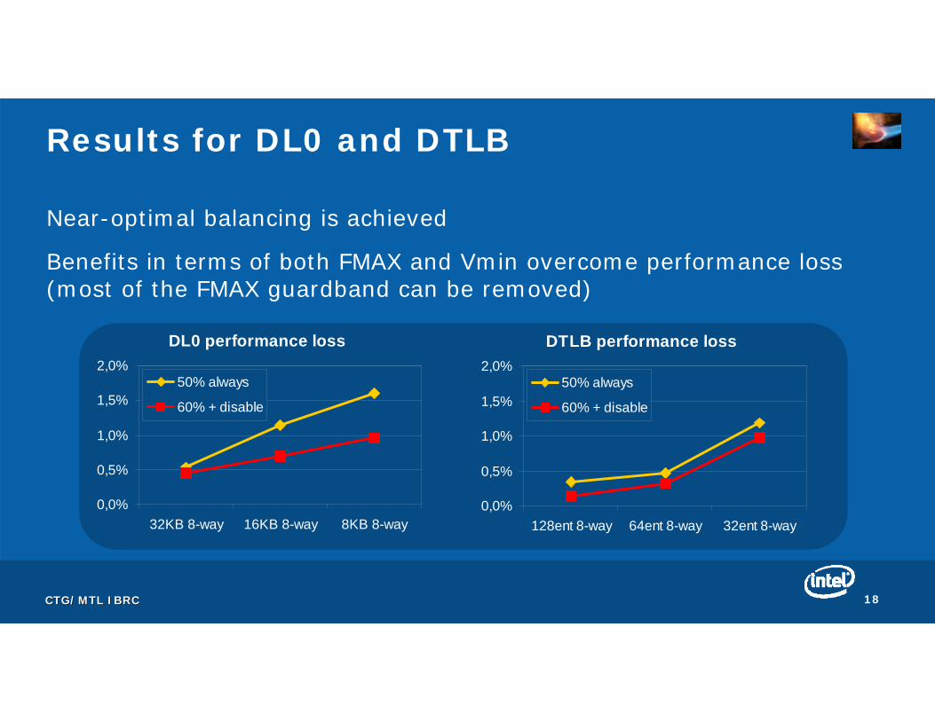
Results for DL0 and DTLB
Near-optimal balancing is achieved
Benefits in terms of both FMAX and Vmin overcome performance loss (most of the FMAX guardband can be removed)
DTLB performance loss
0,0%
0,5%
1,0%
1,5%
2,0%
128ent 8-way 64ent 8-way 32ent 8-way
50% always
60% + disable
DL0 performance loss
0,0%
0,5%
1,0%
1,5%
2,0%
32KB 8-way 16KB 8-way 8KB 8-way
50% always
60% + disable

CTG/MTL IBRCCTG/MTL IBRC 19
Agenda
•Understanding NBTI and its impact
•Solutions for sequential blocks
•Solutions for combinational blocks
•Conclusion
CTG/MTL IBRCCTG/MTL IBRC 20
Managing Inputs for Combinational Logic
During idle periods inputs remain the same• The same PMOS degrade
If different inputs are used, different PMOS will degrade • None of the PMOS will degrade too much
• Maximum duty cycle is reduced
Set special inputs during idle periods to reduce maximum degradation• Alternate different inputs in a round-robin fashion during idle periods
More details in the paper

CTG/MTL IBRCCTG/MTL IBRC 21
Results for an Adder
Inputs have been chosen to degrade different PMOS
Few inputs are enough to balance the degradation
NBTI Guardband
0%
4%
8%
12%
16%
20%
24%
real inputs 30% real + 000 +111
21% real + 000 +111
11% real + 000 +111
inputs

CTG/MTL IBRCCTG/MTL IBRC 22
Agenda
•Understanding NBTI and its impact
•Solutions for sequential blocks
•Solutions for combinational blocks
•Conclusion

CTG/MTL IBRCCTG/MTL IBRC 23
Conclusion
Whole processor protected with minor modifications
Sequential blocks• Non-critical access time: invert periodically all contents
• Critical access time: invert invalid contents
Combinational blocks• Set special inputs during idle periods
Guardbanding may be reduced• FMAX is higher performance is boosted; Vmin is lower power is reduced
Future work: take a look to NMOS (PBTI)

CTG/MTL IBRCCTG/MTL IBRC 24
Q&A

CTG/MTL IBRCCTG/MTL IBRC 25
Acknowledgements
Alex Pineiro, IBRC/MTL
Javier Carretero, IBRC/MTL
Pedro Chaparro, IBRC/MTL
Chris Wilkerson, OML/MTL
Nam Sung Kim, CRL/MTL
Ronny Ronen, IDC/MTL
Shekhar Borkar, MTL
Joe Schutz, MTL